

Page 1

t
n
i
e
D
a
c
r
n
th
e
V
B
s
i
oFo
a
m
9
a
V
u
l
e
g
u
a
2
o
t
p
v
Aut
t
a
t
d
9
w
l
o
m
0
o
t
M
og Compon
cal Technolo
77
Frazee Aven
rtmouth, Nov
D
Te
l: 1-902-468-2
ail: focal@m
E
nts Group, H
ies Corpora
e
Scotia, Cana
63 • Fax: 1-
og.com • ww
lifax Operati
ion
a B3B 1Z4
02-468-2249
.moog.com/
ns
arine
Res
The i
dupl
cons
rictions on
formation
cated or dis
nt of Focal
Fibe
isclosure
nd data fur
losed to a
Technologi
Optic
(FM
U
ished in thi
ird party, e
s Corp.
Model
ideo/D
-X-2.5
ser's G
document
ther in who
03
ta Mul
ersion)
ide
Re
Re
Da
are deemed
e or in part,
iplexer
ort No.:
ision:
hor(s):
e of Issue:
confidentia
without the
903-0623A
ACC
November
and shall n
express wri
0
15, 2011
t be
ten
Page 2
903-0623-00 Rev. A Model 903 User's Guide, FMB-X-2.5 Version
REVISION HISTORY
Revision Details of Revision Author(s)
A Preliminary issue, based on 903-0602-00 Rev. C ACC 11/15/2011
REFERENCE DOCUMENTS
Document Number Document Title/Description
903-0602-00 Rev. C Model 903 Fiber Optic Video/Data Multiplexer User's Guide
903-0622-00 Rev. 2 FMB-X-2.5 Diagnostics Manual
700-0425-00 Rev. 2 FMB-X User's Guide
907-0601-00 Rev. C Model 907 Fiber Optic Video/Data Multiplexer User’s Guide
Date
(mm/dd/yyyy)
Focal Technologies Corp. Page
i
Page 3

903-0623-00 Rev. A Model 903 User's Guide, FMB-X-2.5 Version
i
TABLE OF CONTENTS
1.0 Introduction ................................................................................................................................. 1-1
2.0 System Overview ........................................................................................................................ 2-1
2.1 Rack Configuration ....................................................................................................................... 2-2
2.2 Electrical Configuration ................................................................................................................. 2-4
2.3 Optical Configuration .................................................................................................................... 2-5
3.0 Fiber Multiplexers and Backplanes .......................................................................................... 3-1
3.1 FMB-X-2.5 Fiber Multiplexer Board .............................................................................................. 3-1
3.1.1 Remote FMB-X-2.5 .......................................................................................................... 3-1
3.1.2 Console FMB-X-2.5 ......................................................................................................... 3-3
3.1.3 Configuration Settings ..................................................................................................... 3-5
3.2 Backplanes -X............................................................................................................................... 3-6
3.3 Power Supply................................................................................................................................ 3-9
4.0 Video Cards ................................................................................................................................. 4-1
4.1 VIB-X Video Board ....................................................................................................................... 4-1
4.1.1 Input/Output ..................................................................................................................... 4-2
4.1.2 Configuration Settings ..................................................................................................... 4-3
5.0 Data Cards ................................................................................................................................... 5-1
5.1 DIB-232 - RS-232 Interface Board ............................................................................................... 5-1
5.1.1 Input/Output ..................................................................................................................... 5-1
5.1.2 Configuration Settings ..................................................................................................... 5-2
5.2 DIB-232-16 - High Density RS-232 Card ..................................................................................... 5-4
5.3 DIB-485 - RS-422/485 Data Interface Board ................................................................................ 5-7
5.3.1 Input/Output ..................................................................................................................... 5-7
5.3.2 Configuration Settings ..................................................................................................... 5-9
5.4 CIB-10 Control Interface Board .................................................................................................. 5-12
5.5 EIB-10/100 Ethernet Board (Electrical Version) ......................................................................... 5-16
5.5.1 Input/Output ................................................................................................................... 5-17
5.5.2 Configuration Settings ................................................................................................... 5-18
5.5.3 Flow Control .................................................................................................................. 5-21
5.6 AIB-4 - Adaptable Interface Board ............................................................................................. 5-22
5.6.1 Plug-In Modules ............................................................................................................. 5-25
5.6.2 RS-232 Plug-In (AIB-232/TRIGGER) ............................................................................ 5-25
5.6.3 RS-485/422/TTL Plug-In (AIB-485) ............................................................................... 5-26
5.6.4 Tritech Sonar ARCNET Plug-In (AIB-ARCNET) ........................................................... 5-29
5.6.5 Hydrophone/Analog Plug-In (AIB-HYDRO) ................................................................... 5-31
5.6.6 MS-900 Analog Sonar Plug-In (AIB-MS900) ................................................................. 5-33
5.6.7 CANBUS Plug-In (AIB-CANBUS) .................................................................................. 5-34
5.7 907-232E Data Board (8-Channel RS-232) ............................................................................... 5-37
5.7.1 Input/Output ................................................................................................................... 5-37
5.7.2 Configuration Settings ................................................................................................... 5-38
5.8 907-485E Data Board (8-Channel RS-485/422) ........................................................................ 5-40
5.8.1 Input/Output ................................................................................................................... 5-40
5.8.2 Configuration Settings ................................................................................................... 5-42
6.0 Media Converter Cards .............................................................................................................. 6-1
6.1 ECL-02 - Dual ECL Interface Board ............................................................................................. 6-1
6.2 EIB-10/100 Ethernet Interface Board ........................................................................................... 6-5
6.2.1 Input/Output ..................................................................................................................... 6-6
6.2.2 Configuration Settings ..................................................................................................... 6-6
6.2.3 Flow Control .................................................................................................................... 6-6
6.2.4 Optical Configuration ....................................................................................................... 6-6
Focal Technologies Corp. Page
i
Page 4

903-0623-00 Rev. A Model 903 User's Guide, FMB-X-2.5 Version
i
6.3 GBES 4 Port Gigabit Ethernet Switch Board ................................................................................ 6-8
6.3.1 Input/Output ..................................................................................................................... 6-8
6.3.2 Configuration Settings ..................................................................................................... 6-9
6.4 HD-SDI Video Board .................................................................................................................. 6-10
6.4.1 Input/Output ................................................................................................................... 6-10
6.4.2 Configuration Settings ................................................................................................... 6-11
7.0 Fiber Optics ................................................................................................................................. 7-1
7.1 Safety ............................................................................................................................................ 7-1
7.2 System Design.............................................................................................................................. 7-1
7.3 Fiber Handling Guidelines ............................................................................................................ 7-3
8.0 Installation and Operation ......................................................................................................... 8-1
8.1 Mounting ....................................................................................................................................... 8-1
8.2 Cooling .......................................................................................................................................... 8-2
8.3 Diagnostics ................................................................................................................................... 8-2
8.4 Bench Test .................................................................................................................................... 8-3
8.5 Maintenance ................................................................................................................................. 8-5
8.6 Model 903 Board Handling ........................................................................................................... 8-6
APPENDICES
Appendix A – Connector Part Numbers and Pin Assignments
Appendix B – Fuses
Appendix C – Guidelines to Upgrade to FMB-X-2.5 Systems
Appendix D – Obsolete Systems
LIST OF FIGURES
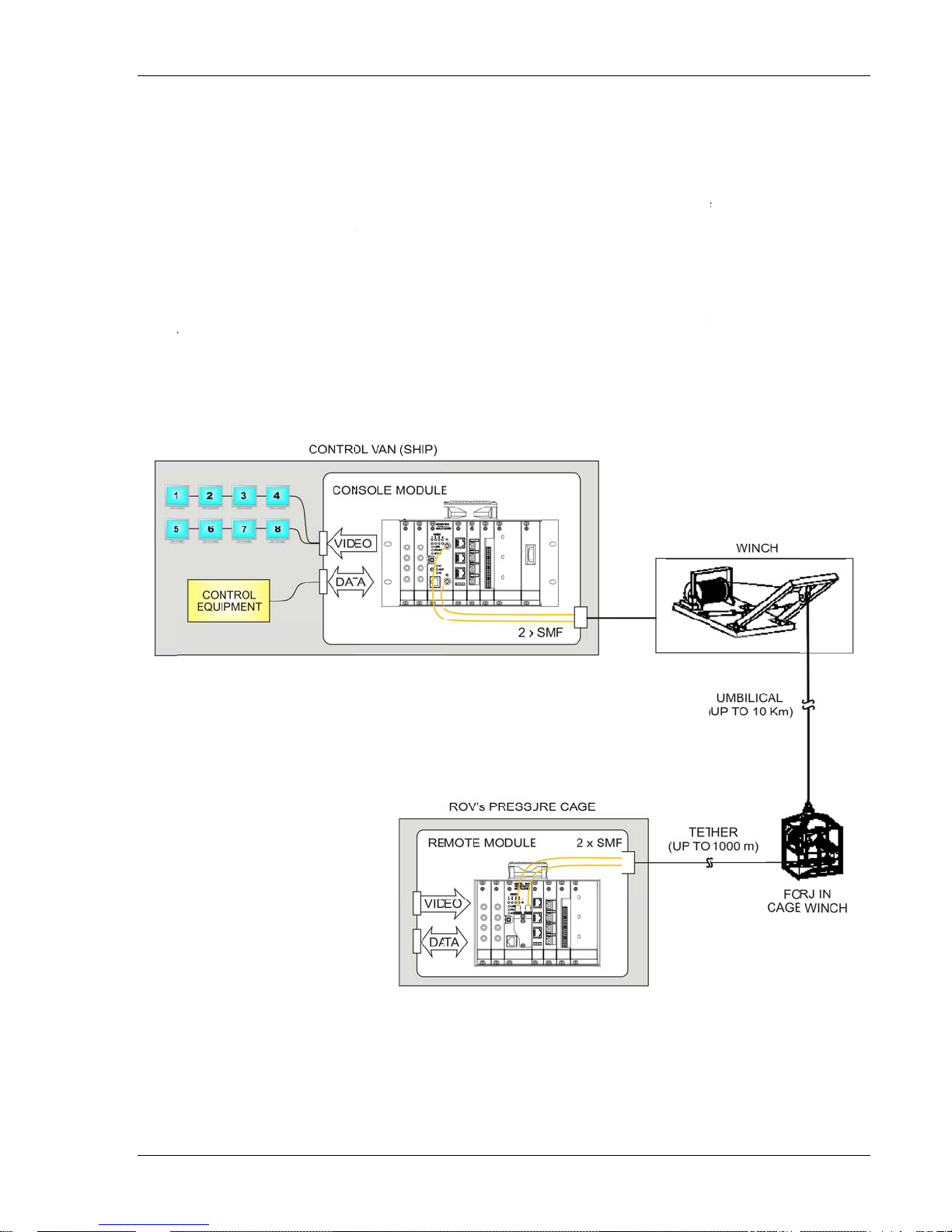
Figure 2.0-1: Model 903 Multiplexer, Typical ROV Application…………………………………….…………2-1
Figure 2.1-1: Model 903 Console & Remote Front Panel View – Typical Card Configuration.................. 2-3
Figure 2.2-1: Model 903 Signal Configuration ........................................................................................... 2-4
Figure 2.3-1: Model 903 Fiber Optic Transmission System ...................................................................... 2-5
Figure 2.3-2: Model 903 Fiber Optic Transmission System Expanded ..................................................... 2-6
Figure 3.1-1: Remote FMB-X-2.5 Front Panel View .................................................................................. 3-1
Figure 3.1-2: Remote FMB-X-2.5 Plan View ............................................................................................. 3-2
Figure 3.1-3: Console FMB-X-2.5 Front Panel .......................................................................................... 3-3
Figure 3.1-4: Console FMB-X-2.5 Plan View ............................................................................................ 3-5
Figure 3.2-1: 28 HP Backplane -X (CBP-121-XR/XC) .............................................................................. 3-7
Figure 3.2-2: 44 HP Backplane -X (CBP-241-XR/XC) .............................................................................. 3-8
Figure 4.1-1: Block Diagram of VIB-X Card .............................................................................................. 4-1
Figure 4.1-2: VIB-X Front Panel ................................................................................................................ 4-2
Figure 4.1-3: VIB-X Plan View ................................................................................................................... 4-4
Figure 5.1-1: DIB-232 Front Panel ............................................................................................. ............... 5-1
Figure 5.1-2: RS-232 3-Pin WAGO Connector (733-103) ......................................................................... 5-2
Figure 5.1-3: DIB-232 PCB ........................................................................................................................ 5-3
Figure 5.2-1: DIB-232-16 High Density RS-232 Board ............................................................................ . 5-4
Figure 5.2-2: DIB-232-16 Motherboard (Daughtercard Not Shown) ......................................................... 5-5
Figure 5.2-3: DIB-232-16 Block Diagram ........................................................................................ .......... 5-6
Figure 5.2-4: DIB-232-16 Input/Output Schematic (Channels 1 and 2) .................................................... 5-6
Figure 5.3-1: DIB-485 Front Panel ............................................................................................. ............... 5-7
Figure 5.3-2: WAGO RS-422/485 data connectors ................................................................................... 5-8
Focal Technologies Corp. Page
ii
Page 5

903-0623-00 Rev. A Model 903 User's Guide, FMB-X-2.5 Version
v
Figure 5.3-3: DIB-485 PCBA ................................................................................................................... 5-11
Figure 5.4-1: CIB-10 Front Panel ............................................................................................................ 5-12
Figure 5.4-2: CIB-10 TOR Input and Output ........................................................................................... 5-13
Figure 5.4-3: CIB-10 PCBA ..................................................................................................................... 5-14
Figure 5.4-4: CIB-10 Block Diagram........................................................................................................ 5-15
Figure 5.4-5: CIB-10 Shield Options........................................................................................................ 5-15
Figure 5.5-1: EIB-10/100 Front Panel ..................................................................................................... 5-16
Figure 5.5-2: EIB-10/100 RJ-45 Grounding Options ............................................................................... 5-18
Figure 5.5-3: EIB-10/100 PCBA .............................................................................................................. 5-19
Figure 5.6-1: Adaptable Interface Board (AIB-4) Front Panel ................................................................. 5-22
Figure 5.6-2: Adaptable Interface Board (AIB-4) PCB ............................................................................ 5-23
Figure 5.6-3: Block Diagram of Adaptable Interface Board (AIB-4) ........................................................ 5-24
Figure 5.6-4: AIB RS-232/TRIGGER Plug-In Module ............................................................................. 5-25
Figure 5.6-5: AIB RS-485 Plug-In Module ............................................................................................... 5-26
Figure 5.6-6: AIB RS-422 Interface Schematic ....................................................................................... 5-27
Figure 5.6-7: AIB Tritech ARCNET Plug-In Module ................................................................................ 5-29
Figure 5.6-8: AIB Hydrophone Plug-In Module ....................................................................................... 5-31
Figure 5.6-9: MS-900 Plug-In Module (Top View) ................................................................................... 5-33
Figure 5.6-10: AIB-CANBUS Plug-In Module (Top View) ....................................................................... 5-34
Figure 5.6-11: WAGO 4-Pin Header........................................................................................................ 5-36
Figure 5.7-1: 907-232E Front Panel ........................................................................................................ 5-37
Figure 5.7-2: 907-232 (8-Channel RS-232) card ..................................................................................... 5-38
Figure 5.7-3: 907-232E Card Side View .................................................................................................. 5-39
Figure 5.8-1: 907-485E Front Panel ........................................................................................................ 5-40
Figure 5.8-2: Wiring recommendation when using the 907-485E in 485 mode (CH1 shown) ................ 5-41
Figure 5.8-3: 907-485 (8-Channel RS-485/422) card .............................................................................. 5-42
Figure 5.8-4: RS-485 Card Side View ..................................................................................................... 5-43
Figure 6.1-1: ECL-02 Front Panel ............................................................................................................. 6-1
Figure 6.1-2: ECL-02 PCBA ...................................................................................................................... 6-3
Figure 6.2-1: EIB-10/100 Front Panel ....................................................................................................... 6-5
Figure 6.2-2: EIB-10/100 Optics Configuration ......................................................................................... 6-7
Figure 6.3-1: GBES Front Panel ................................................................................................................ 6-8
Figure 6.3-2: GBES Side View .................................................................................................................. 6-9
Figure 6.4-1: HD-SDI Front Panel ........................................................................................................... 6-10
Figure 6.4-2: 907-HDV (HD-SDI) Media Converter Card ........................................................................ 6-12
Figure 6.4-3: HD-SDI Card Side View ..................................................................................................... 6-12
Figure 7.2-1: Block Diagram of Model 903 Fiber Optic Transmission System.......................................... 7-1
Figure 7.3-1: LC connector ........................................................................................................................ 7-3
Figure 7.3-2: ST Connector ....................................................................................................................... 7-3
Figure 7.3-3: SFP Transceiver .................................................................................................................. 7-4
Figure 8.1-1: Side View of Typical Model 903 Console Card Cage .......................................................... 8-1
Figure 8.1-2: Side View of Typical Model 903 Remote Card Cage ........................................................... 8-2
Figure 8.4-1: Flux Budget Test Setup – Transmit Optical Power Measurement ....................................... 8-3
Figure 8.4-2: Flux Budget Test Setup – Link Threshold Measurement ..................................................... 8-4
Figure 8.4-3: Flux Budget Test Setup – Received Sensitivity Measurement ............................................ 8-4
LIST OF TABLES
Table 3.1-1: FMB-X-2.5 Front Panel LEDs ............................................................................................... 3-3
Table 3.1-2: RS-232 Diagnostic Port Connections .................................................................................... 3-4
Table 3.1-3: SW1 Configuration Settings .................................................................................................. 3-5
Table 3.1-4: SW2 Configuration Settings .................................................................................................. 3-5
Table 3.2-1: Typical Rack Sizes and “-X” Backplanes .............................................................................. 3-6
Table 4.1-1: VIB-X Card Configuration Settings (Switch SW3) ................................................................. 4-3
Table 4.1-2: VIB-X Input/Output Video Format Configuration (Switch SW1) ............................................ 4-3
Focal Technologies Corp. Page
i
Page 6

903-0623-00 Rev. A Model 903 User's Guide, FMB-X-2.5 Version
v
Table 5.1-1: Pin Designations for DIB-232 Connectors ............................................................................ 5-2
Table 5.3-1: DIB-485 Channel Configuration ........................................................................................... 5-8
Table 5.3-2: WAGO Pin Designations ....................................................................................................... 5-8
Table 5.3-3: DIB-485 Configuration Settings (Defaults Shaded) ............................................................ 5-10
Table 5.5-1: RJ-45 Pin Assignments ....................................................................................................... 5-17
Table 5.5-2: EIB-10/100 Front Panel LEDs ............................................................................................. 5-17
Table 5.5-3: RJ-45 Individual Port Settings ............................................................................................. 5-20
Table 5.5-4: Global Port Settings ............................................................................................................ 5-20
Table 5.6-1: AIB Plug-in Modules ............................................................................................................ 5-25
Table 5.6-2: AIB-232/TRIGGER Pin Designations .................................................................................. 5-25
Table 5.6-3: AIB-485 Pin Designations ................................................................................................... 5-27
Table 5.6-4: Configuration Settings for AIB RS-485 Module (Defaults Shaded) .................................... 5-28
Table 5.6-5: Configuration Settings for AIB Tritech Module (Defaults Shaded) ...................................... 5-29
Table 5.6-6: AIB-ARCNET Pin Designations .......................................................................................... 5-30
Table 5.6-7: Configuration Settings for AIB Hydrophone Module ........................................................... 5-31
Table 5.6-8: Hydrophone Gain Settings (Defaults Shaded) .................................................................... 5-31
Table 5.6-9: AIB-HYDRO Pin Designations ............................................................................................ 5-32
Table 5.6-10: AIB-MS900 Pin Designations ............................................................................................ 5-33
Table 5.6-11: AIB-CANBUS On-board LEDs .......................................................................................... 5-35
Table 5.6-12: CAN Speed Settings ......................................................................................................... 5-35
Table 5.6-13: AIB-CANBUS Pin Designations ........................................................................................ 5-36
Table 5.7-1: RS232 Data Connector Pin Outs ........................................................................................ 5-38
Table 5.7-2: Input / Output Ratings ......................................................................................................... 5-38
Table 5.8-1: 485/422/TTL Data Connector Pin Outs ............................................................................... 5-41
Table 5.8-2: Input / Output Ratings ......................................................................................................... 5-41
Table 5.8-3: SW1 - SW8, SW10 RS485/422 Configuration .................................................................... 5-42
Table 6.1-1: ECL-02R/C Configuration Switch Settings ............................................................................ 6-2
Table 6.3-1: GBES Switches Default Settings .......................................................................................... 6-9
Table 6.4-1: SW1 Options ....................................................................................................................... 6-11
Table 6.4-2: SW2 Options ....................................................................................................................... 6-11
Table 7.2-1: Typical ROV System Flux Budget ......................................................................................... 7-2
Focal Technologies Corp. Page
Page 7

903-
0
l
f
o
gi
c
t
s
s
s
z
o
o
aany
a Alw
n
oobs
o
n
a
n
e
s
e
h
y
t
e
b
w
h
o
s
o
c
t
a
w
d
o
f
u
e
m
t
e
u
e
r
k
D
a
d
a
a
a
d
w
e
r
e
p
e
o
m
E
5
z
o
u
s
s
e
k
e
i
Sa
The f
ety Pre
623-00 Rev.
llowing safe
A
aution
y precaution
Thi
ha
inju
Bef
volt
Bef
off
should be
product is i
ards and are
ry. Do not m
re connecti
age is within
re removing
nd disconn
circuit unles
bserved bef
tended for u
familiar with
ke module c
g this produ
the specifica
or installing
cted from po
recommen
Model 903
re using this
e by qualifi
safety preca
onnections u
t to the pow
ions of the p
a board, ma
er source.
ed by the m
User's Gui
product.
d personnel
tions requir
nless qualifie
r source, ve
roduct’s pow
e sure the m
o not attem
nufacturer.
e, FMB-X-2.
ho recogni
d to avoid p
d to do so.
ify that the o
r supply.
ain module i
t to modify o
Version
e shock
ssible
tput
turned
r repair
Pro
tect the pow
ag
inst them.
ays unplug t
Do
not block an
Do
not look into
acti
ve fiber, esp
mic
roscope.
Ha
dle optical fi
mis
handled.
Gr
unded ESD
erved when
r cable from
e power cab
ventilation
he end of a
cially when
er with extr
rist straps
andling prin
being walke
le at the plug
penings or f
iber when it i
sing a magn
me care. Gl
ust be worn
ed circuit bo
on or pinch
, do not pull
ns.
s plugged int
ifying instru
ss fiber is su
and proper
rds.
d by items p
n the cord it
o a transceiv
ent, such as
bject to brea
SD safety pr
laced or
elf.
r or
a fiber
age if
cautions
Foca
Technolo
es Corp.
Page
v
Page 8

903-0623-00 Rev. A Model 903 User's Guide, FMB-X-2.5 Version
i
ACRONYMS AND ABBREVIATIONS
AIB Adaptable Interface Board
APD Avalanche Photodiode
CIB Control Interface Board (T OR)
CWDM Coarse Wavelength Division Multiplexer
DIB Data Interface Board
ECL Emitter Coupled Logic
EIA Electronic Industries Association
EIB Ethernet Interface Board
ESD Electrostatic Discharge
FC/APC Ferrule Connector (Threaded optical connector) / Angled Physical Contact
FC/PC Ferrule Connector (Threaded optical connector) / Physical Contact
FMB Fiber (Optic) Multiplexer Board
FORJ Fiber Optic Rotary Joint
FPGA Field Programmable Gate Array
Gbps Gigabits Per Second
I/O Input/output
kbps Kilobits Per Second
LED Light Emitting Diode
Mbps Megabits Per Second
MDI/MDIX Automatic medium-dependent interface crossover
NRZ Non Return to Zero (Data Signaling)
NTSC National Television System Committee (Composite Video Format)
P/N Part Number
PAL Phase Alternation Line (Composite Video Format)
PCBA Printed Circuit Board Assembly (Populated PCB)
PECL Positive Emitter Coupled Logic
PLD Programmable Logic Device
RGB Red, G reen, Blue (Component Video)
ROV Remotely Op erated Vehicle
SERDES Serializer/Deserializer
SMB Sub-Miniature “B” (Connector)
SMT Surface Mount Technology
ST/PC Straight Tip optical connector / Physical Contact
TDM Time Division Multiplexing
TTL Transistor-Transistor Logic
VOAT Variable Optical Attenuator
WDM Wavelength Division Multiplexer
Y/C Luminance/Chrominance
Focal Technologies Corp. Page
vi
Page 9

903-0623-00 Rev. A Model 903 User's Guide, FMB-X-2.5 Version
1.0 Introduction
Focal's Model 903 is a video/data multiplexer and fiber optic transmission system designed for Remotely
Operated Vehicle (ROV) applications. The Model 903 uses Time Division Multiplexing (TDM) and
Wavelength Division Multiplexing (WDM) to provide high multiplexing density in a compact, low-power
package. Typical systems support 8 broadcast quality composite video channels, up to 64 digital
channels, and 2 additional bidirectional optical channels for high-speed son ar, digital video, or 1 Gbps
Ethernet links.
This user’s guide provides complete information on the design, configuration, installation and operation of
the Model 903 multiplexer system based on FMB-X-2.5 cards. This manual and the appropriate
reference documents should be reviewed prior to installation or reconfiguration of the multiplexer.
Some sections of the manual apply to optional cards or features that are not included with the delivered
system but may be added later.
Appendices include the following information:
Appendix A - A list of connectors and pin configurations
Appendix B - A list of all fuses used in the system
Appendix C - Guidelines for upgrading from FMB to FMB-X-2.5 base systems
Appendix D - Obsolete systems included in this manual for reference
Focal Technologies Corp. Page 1-1
Page 10
903-
0
l
s
a
M
o
r
c
o
gi
m
m
n
o
c
o
s
n
o
e
v
s
3
g
e
s
n
e
p
-
s
e
C
5
m
n
3
o
d
t
s
r
i
e
c
e
h
r
n
e
e
O
d
t
f
n
c
e
a
o
5
e
a
d
n
5
u
623-00 Rev.
A
Model 903
User's Gui
e, FMB-X-2.
Version
2.0
Each
a 3U
Eurocard co
Each
nece
typic
The
up to
64 data cha
Vide
unidi
ectional: the
generally ha
cards
inter
hangeable b
The f
Syste
Model 903
module is pr
sary optical
lly varying fr
odel 903 sy
cards are n
llowing figur
Over
ultiplexer sy
sole module
vided compl
omponents.
m 4 HP (20.
tems based
nels. The ag
t interchang
remote card
ve bidirectio
tween the r
shows a ty
iew
tem consist
(surface or s
etely packag
Eurocard P
mm) to 8 H
on FMB-X-2.
regate data
able betwee
have video i
al and sym
mote and co
ical ROV ap
of a 3U Eur
hipboard en
d with an in
B dimension
P (40.6 mm).
motherboa
uplink/downl
n the remote
nputs and th
etrical data
sole modul
plication of t
card remote
), often mou
egrated pow
are 100 x 1
ds support 8
nk rate, inclu
and console
console vid
hannels and
s.
e Model 903
module (sub
ted inside a
r supply uni
60 mm with
simultaneou
ding formatti
module, sin
o cards hav
hence the c
system.
sea or ROV
standard 19”
(PSU) and
ront panel wi
s video chan
g bits, is 2.
e the signals
video outp
rds are usua
nd) and
rack.
ll
ths
els and
Gbps.
are
ts. Data
lly
Figure 2.0
Foca
Technolo
es Corp.
1: Model 90
Multiplexe
r, Typical R
V Applicati
n
Page 2-1
Page 11

903-0623-00 Rev. A Model 903 User's Guide, FMB-X-2.5 Version
2.1 Rack Configuration
Various rack widths are available, supporting different numbers of slots for card installation. Typically a
903 rack has 2 slots for video cards, 1 slot for the FMB-X-2.5, 3-4 slots for data cards, and 1 slot for a
Eurocassette PSU. Many remote racks substitute a DC-DC module on the back cover in place of the
Eurocassette PSU to reduce the width of the rack by 8 HP (4 HP = 0.8" or 20.3 mm). The remote rack
usually has a wire pigtail for applying AC or DC power; the console rack generally has a front panel
switch and an IEC-320 jack on the rear cover to support a variety of plug cables. Console modules can be
provided in full 19" racks or as reduced width sub-racks with add-on flanges for installation in 19" racks.
Slots in each rack are referenced by letter, per the installation drawings. Slots A and B are 4 HP wide and
are intended for video cards, slot C is an 8 HP slot for the FMB-X-2.5, slot D and above are typically 4 HP
wide data slots with the exception of the last slot, which is usually 8HP for the power supply module. The
console module usually includes an additional panel for the power switch.
Some racks include one or two slots dedicated for media converter cards. Thes e slots provide only power
at the backplane connectors, since the media converters do not require any backplane data lines. Media
converters may also be installed in data slots, which in this case the backplane data lines are unused.
Optical expansion cards, such as CWDMs may be installed in any video, data or media converter slot.
Refer to installation drawings 903-8XXX-XX for the actual as-built rack configuration.
Focal Technologies Corp. Page 2-2
Page 12
903-0623-00 Rev. A Model 903 User's Guide, FMB-X-2.5 Version
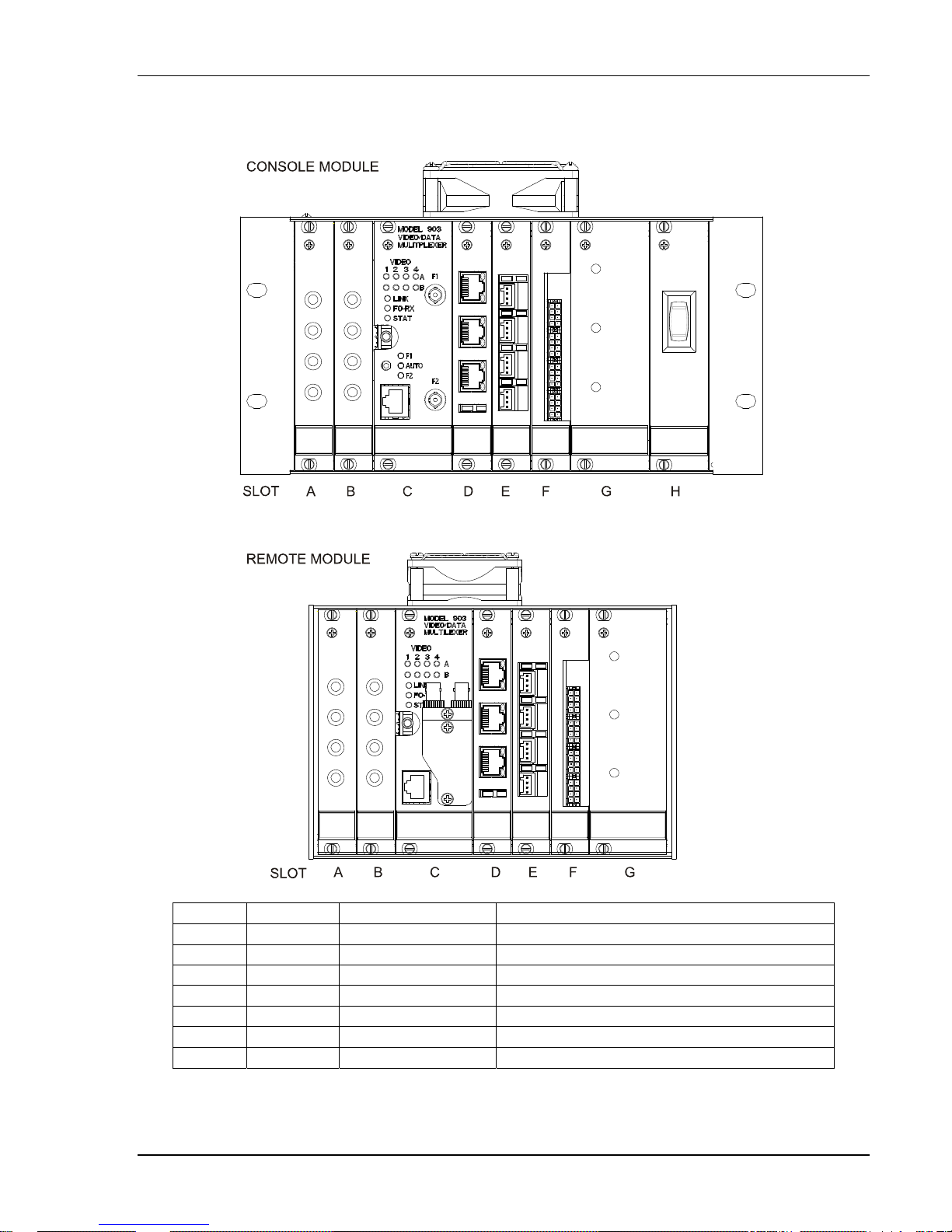
The following figure shows front panel views of a 903 remote and console module with typical card
configuration.
SLOT(S) SLOT TYPE CARD/MODULE NAME DESCRIPTION
A,B VIDEO VIB-X 4 X VIDEO CARD
C FMB FMB-X-2.5 FIBER MULTIPLEXER BOARD “-X-2.5” VERSION
D DATA EIB-10/100 3 X 10/100 Mbps ETHERNET CARD
E DATA AIB-4 4 X DATA, ADAPTABLE INTERFACE BOARD
F DATA 907-232E 8 X RS-232 907-232E CARD
G PS POWER SUPPLY POWER SUPPLY UNIT
H PS SWITCH POWER SWITCH PANEL ASSY (CONSOLE)
Figure 2.1-1: Model 903 Console & Remote Front Panel View – Typical Card Configuration
Focal Technologies Corp. Page 2-3
Page 13
903-0623-00 Rev. A Model 903 User's Guide, FMB-X-2.5 Version
2.2 Electrical Configuration
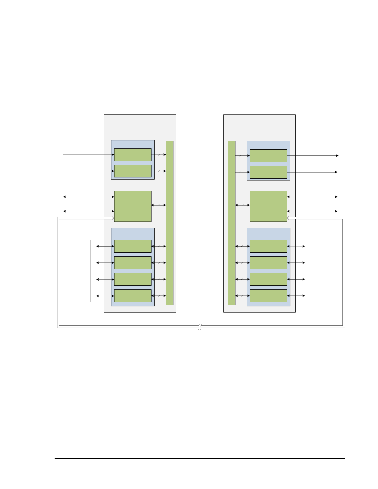
The following figure shows the signal configuration of a Model 903 system. Each video card
"pre-multiplexes" four video channels on 10 video lines to the FMB-X-2.5 resulting in 10-bit digitization for
each video channel. Each data card slot has 5 lines on the backplane to and from the FMB-X-2.5. In total
there are 20 data lines. Some data cards, such as the AIB-4, map a single data input to a single data line
to the FMB-X-2.5. Other data cards, such as the CIB-10 and DIB-232-16, map several data channels to a
single line to the FMB-X-2.5.
MODEL 903
REMOTE MODULE
MODEL 903
CONSOLE MODULE
4 x Video Inputs
(Composite)
4 x Video Inputs
(Composite)
1 x Ethernet
10/100 Mbps
1 x RS-232
Data
Input/Output
(Up to 64
3
Channels
)
VIDEO CARDS
VIB-X
VIB-X
1
FIBER
2
MULTIPLEXER
BOARD
(FMB-X-2.5)
DATA CARDS
Data Card 1
Data Card 2
Data Card 3
Data Card 4 Data Card 4
10
10
40
BACKPLANE-X
5
5
5
5
OPTICAL CABLE SYSTEM
BACKPLANE-X
4
10
10
40
5
5
5
5
VIDEO CARDS
VIB-X
VIB-X
FIBER
MULTIPLEXER
BOARD
(FMB-X-2.5)
DATA CARDS
Data Card 1
Data Card 2
Data Card 3
4 x Video Outputs
(Composite)
4 x Video Outputs
(Composite)
1 x Ethernet
10/100 Mbps
1 x RS-232
1
2
Data
Input/Output
(Up to 64
Channels
3
Notes:
1. System diagnostics is available via the 10/100 Mbps Ethernet port as Modbus TCP/IP or through an embedded web
server. Diagnostic packets are handled as low priority and must be polled by the external computer. When accessed,
diagnostic packets use up less than 0.1 % of the Ethernet channel capacity.
2. RS-232 port on the FMB-X-2.5 is for system diagnostics only.
3. Up to 64 data channels calculated using 4 x 16 high density RS-232 (DIB-232-16) cards.
4. Refer to “Optical Configuration” section of this manual for details about the optical configuration of the Model 903
system.
)
Focal Technologies Corp. Page 2-4
Figure 2.2-1: Model 903 Signal Configuration
Page 14
903-0623-00 Rev. A Model 903 User's Guide, FMB-X-2.5 Version
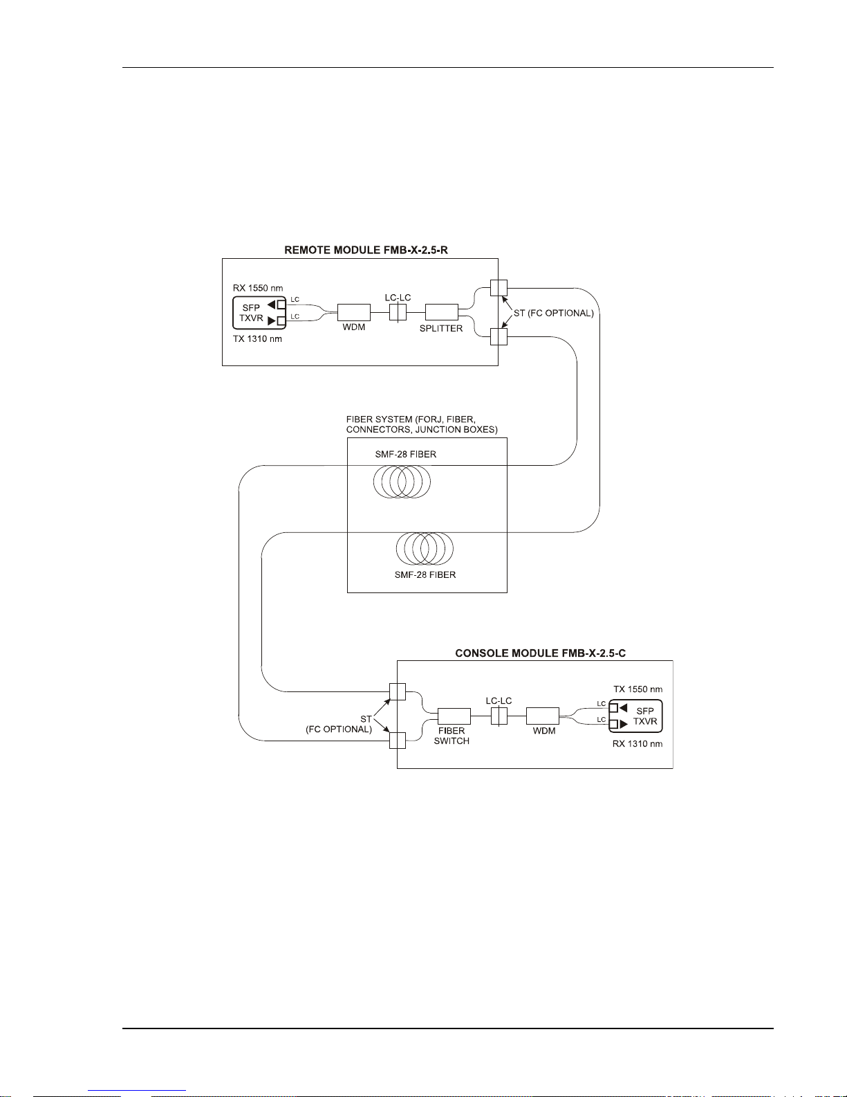
2.3 Optical Configuration
Model 903 systems based on FMB-X-2.5 cards are provided in standard optical configurations with
singlemode fiber and dual fiber connection for redundancy. Typical systems u se 1310 nm as the uplink
wavelength (remote to console) and 1550 nm as the downlink wavelength (console to remote), which are
combined with a wavelength division multiplexer (WDM) on the FMB-X-2.5. Dual fiber configurations
increase reliability with an integrated splitter at the remote FMB-X-2.5 and an automatic fiber switch at the
console FMB-X-2.5, as shown in the figure below.
Figure 2.3-1: Model 903 Fiber Optic Transmission System
Standard FMB-X-2.5 cards use lasers with loosely controlled wavelengths that can vary significantly from
unit to unit and over temperature. Since 1310 nm and 1550 nm are widely separated on the optical
spectrum, there is no problem with crosstalk or interference even when the exact wavelengths are
variable.
FMB-X-2.5 cards are also available with more carefully controlled wavelengths for use in multi-channel
systems based on CWDM (Coarse Wavelength Division Multiplexing) or DWDM (Dense Wavelength
Division Multiplexing). CWDM systems support 4 to 16 wavelengths; DWDM systems support 16 or more
wavelengths. Both CWDM and DWDM enable the combination of two or more FMBs, plus other media
converter cards, on a single optical fiber, allowing considerable expansion of the Model 903 video and
data channel capacity.
Focal Technologies Corp. Page 2-5
Page 15

903-0623-00 Rev. A Model 903 User's Guide, FMB-X-2.5 Version
CWDM wavelengths may be used to expand an existing Model 903 system by adding separate optical
links, typically for high-speed sonar, Gigabit Ethernet or HD-SDI Video. Daisy-chaining media converter
cards (cards with on-board optical transceivers using CWDM wavelengths) into the existing
1310/1550 nm optical link allow the upgraded system to continue operating on a single fiber. Media
converter cards such as the ECL-02, EIB-10/100 (optical version) or HD-SDI may be installed in any data
card slot.
The figure below shows an example of an expanded Model 903 fiber optic transmission system using
media converter cards with CWDM wavelengths. In this example, the remote and console media
converter cards are “daisy chained” into an existing 1310/1550 nm system and four waveleng t hs are
used. The media converter card uses 1471 nm and 1491 nm wavelengths and the FMB-X-2.5 card uses
1310 nm and 1550 nm wavelengths. Note that the 903 system continues operating on a single fiber
(second fiber is optional). Refer to section 6.0 for more information about the media converter cards
available for Model 903 systems.
Figure 2.3-2: Model 903 Fiber Optic Transmission System Expanded
Systems that require more than four wavelengths must use a dedicated CWDM card to combine all
wavelengths. (Also all transceivers must be CWDM wavelengths.) Optical configuration drawings are
provided for systems with more than two wavelengths.
Focal Technologies Corp. Page 2-6
Page 16

903-0623-00 Rev. A Model 903 User's Guide, FMB-X-2.5 Version
A
V
V
A
3.0 Fiber Multiplexers and Backplanes
Fiber Multiplexer Boards (FMBs) are used to combine all of the video, Ethernet, and data signals into a
single optical link and then regenerate the original copper signals at the other end of the system.
Backplane cards are used to connect all of the Model 903 cards together within remote or console
modules. A complete Model 903 system includes at least one remote and one console module.
3.1 FMB-X-2.5 Fiber Multiplexer Board
The FMB-X-2.5 cards use FPGA SERDES (Serializer/Deserializer) modules that run at an optical data
rate of 2.5 Gbaud on both uplink and downlink. This high optical data rate allows more capacity for video,
data and Ethernet traffic than older FMBs. FMB-X-2.5 cards are designed to work only with singlemode
fibers to support the high data rates. System diagnostics can be accessed via the RS-232 port or RJ-45
Ethernet port of both remote and console FMB-X-2.5 cards. More information about diagnostics is
provided in Appendix D and the diagnostics manual (P/N 903-0622-00).
Note: The FMB-X-2.5 FPGA-based SERDES optical link is not backwards compatible with FMB-VTX,
FMB-VRX or GLINK FMB-X cards. More details about upgrading to FMB-X-2.5 are found in Appendix C.
Details on the GLINK-FMB-X cards are given in Appendix D.
3.1.1 Remote FMB-X-2.5
Card P/N 903-5082-00
The front panel view of the remote FMB-X-2.5 is shown in the figure below. Redundant ST fiber
connectors are accessible on the right angled turret. An internal splitter provides roughly equal powe r
output levels on both ST connectors. Output power should be greater than -6 dBm at 1310 nm (uplink).
Receive sensitivity at the turret should be better than -26 dBm at 1550 nm (downlink). Front panel LEDs
provide critical status indicators described in detail in section 3.1.2.
MODEL 903
BLANK OR 10M = GLINK FMB-X
ETHERNET RATE TEXT
100M = FMB-X-2.5
VIDEO SYNC
LEDS (SLOT A/B)
STATUS LEDS
(LINK, FO-RX, STAT)
DIAGNOSTICS SERIAL
PORT (RS-232)
MULTIPLEXER
100M
IDEO
1234
B
LINK
FO-RX
STAT
IDEO/DAT
REDUNDANT
FIBER PORTS
(SPLITTER)
DUAL ST/PC
ETHERNET PORT
OPTICAL LINK RATE
GLINK FMB-X = 10M
FMB-X-2.5 = 100M
Figure 3.1-1: Remote FMB-X-2.5 Front Panel View
Focal Technologies Corp. Page 3-1
Page 17

903-0623-00 Rev. A Model 903 User's Guide, FMB-X-2.5 Version
LEDs on the front panel match those described in the console FMB-X-2.5 section and allow direct
monitoring of the optical link status (LINK), optical receive power (FO-RX), and the status (STAT) of the
on-board diagnostics. See the console FMB-X-2.5 section for more details on LEDs.
The Ethernet port supports both 10 Mbps and 100 Mbps devices on the copper link. The optical Ethernet
link through the multiplexer is 100 Mbps.
Diagnostics for the FMB-X-2.5 can be accessed at the RS-232 port on both remote and console cards,
and also via the RJ-45 Ethernet port at both remote and console ends. See console FMB-X-2.5 for more
information about diagnostics.
A plan view of the remote FMB-X-2.5 is shown in the figure below. The 1310/1550 nm singlemode WDM
coupler and 1 x 2 splitter are not visible: both are mounted on the underside of the optical daughtercard
below the two dual LC bushings shown.
DAUGHTERCARD
OPTICAL
DUAL ST
BUSHING
TURRET
RX 1550 nm
DIN 41612
96-PIN
BACKPLANE
CONNECTOR
SFP CAGE
TRANSCEIVER
SFP
TX 1310 nm
Figure 3.1-2: Remote FMB-X-2.5 Plan View
No customer switch settings are required for configuration of the FMB-X-2.5 remote card. All video
channels are handled at 10-bit digitization and all data slots are sampled as “high speed” slots, similar to
slot “D” on older 903 systems.
Focal Technologies Corp. Page 3-2
Page 18

903-0623-00 Rev. A Model 903 User's Guide, FMB-X-2.5 Version
S
3.1.2 Console FMB-X-2.5
Card P/N 903-5083-00
The front panel view of the console FMB-X-2.5 is shown in the figure below. Redundant ST fiber
connectors are accessible as straight bushings on the front panel marked "F1" and "F2". An internal fiber
switch chooses one of the fibers for the optical link, either automatically or manually via the front panel
toggle switch. Output power should be greater than -2 dBm at 1550 nm (downlink). Receive sensitivity at
the front panel should be better than -28 dBm at 1310 nm (uplink).
ETHERNET RATE TEXT
BLAN K OR 10M = GLINK FMB-X
100M = FMB-X-2.5
VI DEO SYNC
LEDS ( SLOT A/B)
STATUS LEDS
(L INK , FO-R X, ST A T )
DIA GNOSTICS SERIAL
PORT (RS-232)
FIBER SWIT CH
CONTRO L /STATUS
ET HERNE T PORT
OP TICAL L INK RATE
G LIN K FMB- X = 10M
FMB-X-2.5 = 100M
Figure 3.1-3: Console FMB-X-2.5 Front Panel
MODEL 903
VIDEO/DATA
MULTIPLEXER
100M
VIDEO
1234
A
B
LINK
FO-RX
STAT
F1
AUTO
F2
F1
REDUNDANT
FI BER PORT
(SWITCH)
DUAL ST/PC
F2
LEDs on the front panel of the remote or console FMB-X-2.5 provide status of video channels, optical link,
and card health per table below.
LED Description
VIDEO
VIDEO LEDs are green when video sync is detected on each video channel from slot A
and slot B in the rack.
LINK LINK LED is green when a valid optical link is being received and red if no link is present.
FO-RX LED is green when the received optical power is well above threshold. This LED
FO-RX
will change to orange (warning), indicating low margin, or red (alarm), indicating low optical
power. Problems with optical power should be investigated using the diagnostic software
and/or fiber optic power meters.
Focal Technologies Corp. Page 3-3
Table 3.1-1: FMB-X-2.5 Front Panel LEDs
Page 19

903-0623-00 Rev. A Model 903 User's Guide, FMB-X-2.5 Version
LED Description
STAT (Status) LED is green when on-board diagnostic readings are within expected
values. The STAT LED is orange (warning) if any of the on-board diagnostic readings are
close to an alarm state. The STAT LED is red (alarm) if any of the on-board diagnostic
readings are outside of the specified range, in which case the diagnostic software shoul d
STAT
be used to troubleshoot the problem. Monitored signals included temperature and all major
voltage rails (+12V, -12V, +5V, and +3.3V). An alarm state exists if any voltage is worse
than ±20% of nominal value or temperature is > +80C. A warning state exists if any
voltage is worse than ±10% of nominal value or temperature is > +75C, but the reading is
not in an alarm state.
F1/F2 LEDs indicate which fiber is active, per the marked ST bushings. The active fiber is
F1/F2
shown by the green LED. (Toggle up forces the fiber switch to F1 and toggle down forces
it to F2.) The LED(s) will turn red if no link is present.
AUTO
AUTO LED is green when the fiber switch is in automatic mode, as determined by the
toggle switch position. When in automatic mode and there is no link, this LED will be red.
Diagnostics are available at the 1/8" (3.5 mm) stereo jack in RS-232 format compatible with the standard
Model 903 Diagnostics GUI software, e.g. 903-0406-00. Wiring for the RS-232 connections is shown in
the table below.
Table 3.1-2: RS-232 Diagnostic Port Connections
Stereo Jack Pin DB-9F pin Function
1 (Tip) 3 TXD
2 (Middle Ring) 2 RXD
3 (Base Ring) 5 SIG GND
The function described in the table above is relative to the PC, i.e. TXD is data transmitted from the PC to
the FMB-X-2.5 and RXD is data received into the PC from the FMB-X-2.5. This RS-232 interface also has
command based diagnostics, which provides advanced diagnostics information. See 903-0622-00
diagnostic manual for more information.
Diagnostics are also available via the RJ-45 port as Modbus TCP/IP or through an embedded web server.
Since this port is also used for general Ethernet traffic between remote and console, diagnostics packets
are handled as low priority and must be polled by the external computer. When accessed, diagnostic data
packets typically use up less than 0.1% of the Ethernet channel capacity.
The fiber switch may be placed in automatic mode or forced to fiber F1 or F2 using the front panel toggle
switch. In automatic mode, with the toggle switch in the center position, the FMB-X-2.5 tests both fibers
on initial power up and chooses the one with the highest optical power. This will stay locked until the
switch is forced to the other fiber, via the toggle switch, or link is lost on the active fiber. The LED by F1 is
green when that fiber is active – the same applies to F2. The LED marked "AUTO" is green when in
automatic switching mode.
When the optical link is lost, in auto mode, the switch toggles automatically roughly once per second
between F1 and F2 for up to 10 times. If no link is found, the switch returns to the original fiber it was on
before the link failure and waits for a link to be re-established. In this state, the “AUTO”, “F1” and “F 2”
LEDs are red and a continuous audible alarm is produced until a fiber link is restored. Power cycling or
manually forcing the toggle switch to a fiber (F1 or F2 position) and then back to AUTO will reset the
automatic fiber switch.
The FMB-X-2.5 also sounds a continuous audible alarm when an optical link fails in AUTO mode, even if
the other fiber has a valid link. This informs the operator of a fiber fault that otherwise might not be
noticed, as the switchover from one fiber to the other is often seamless. The alarm can be turned off by
Focal Technologies Corp. Page 3-4
Page 20

903-0623-00 Rev. A Model 903 User's Guide, FMB-X-2.5 Version
briefly forcing the toggle switch to the active fiber in manual mode and then back to the automatic setting.
The FMB-X-2.5 alarm can also be disabled via software commands.
A plan view of the console FMB-X-2.5 is shown below. The 1310/1550 nm singlemode WDM coupler is
not visible and is mounted on the underside of the optical daughtercard below the dual LC bushings
shown.
DAUGHTERCARD
OPTICAL
FIBER F1
ST BUSHING
FIBER F2
ST BUSHING
FIBER
SWITCH
RX 1310 nm
DIN 41612
96-PIN
BACKPLANE
CONNECTOR
SFP CAGE
TRANSCEIVER
SFP
TX 1550 nm
Figure 3.1-4: Console FMB-X-2.5 Plan View
3.1.3 Configuration Settings
Switch configuration settings for the remote and console FMB-X-2.5 cards are given in Table 3.1-3 and
Table 3.1-4. Note that both DIP switches (SW1 and SW2) are typically configured at the factory and
therefore the settings should never be changed from their original positions.
Table 3.1-3: SW1 Configuration Settings
Description SW1:1 SW1:2 SW1:3 SW1:4
Remote FMB-X-2.5 ON ON ON ON
Console FMB-X-2.5 OFF ON ON ON
Table 3.1-4: SW2 Configuration Settings
Description SW2:1 SW2:2 SW2:3 SW2:4
High Density Backplanes OFF ON OFF OFF
Standard Backplanes OFF OFF OFF OFF
Focal Technologies Corp. Page 3-5
Page 21

903-
0
l
-
d
a
i
p
e
c
f
A
e
e
e
a
r
A
m
p
w
h
s
D
a
gi
9
e
e
c
e
s
s
f
p
n
R
e
m
f
u
e
H
e
u
e
e
As a
t
s
a
s
e
e
a
y
a
d
x
3
k
X
X
0
X
0
0
0
c
a
s
J
p
o
t
d
c
v
a
a
s
o
a
p
e
m
v
a
C
a
y
m
e
s
p
a
e
G
l
d
t
e
a
m
C
k
o
s
o
t
-
p
m
R
0
e
h
n
N
e
s
v
t
r
e
w
D
R
v
m
1
e
p
a
y
o
d
s
e
n
M
d
u
o
o
v
a
s
G
o
s
b
s
5
m
s
M
c
2
s
s
o
z
t
C
e
e
d
n
o
c
623-00 Rev.
A
Model 903
User's Gui
e, FMB-X-2.
Version
3.2
The “
a Mo
over
A var
Typic
and
to th
FMB-X-2.5
inter
hanged with
identi
slots
pres
Tabl
three
resp
ctively. An “
rack,
which is gen
also
cove
plate.
Backpl
Card P/N
X” backplan
el 903 syste
ll status of th
ety of -X ba
lly each vid
ower supply
ied by letter
and B are
nt, is for the
3.2-1 below
digits followi
vailable. Re
anes -X
03-72XX-00
cards are u
m. The -X ba
system.
kplanes are
o and data
lots are 1.6"
lot. There ar
nother of th
in the install
or video card
ower suppl
shows typic
g the CBP-
” in the suffi
rally 6 HP w
ote racks th
Table
“-X” Rac
CBP-241CBP-231-
CBP-23
CBP-121-
CBP-10
CBP-20
CBP-24
ed to conne
ckplanes pro
vailable with
lot occupies
(8HP) wide.
no address
same type
tion drawing
s, slots D, E
.
l rack sizes
esignator re
indicates th
ider to acco
at do not ha
.2-1: Typic
Type
R/XC
R/XC
-XR
R/XC
-XR
-XR
-XR
t all the Mo
ide diagnos
various com
standard 0.
Boards are r
s to set on
ssuming ju
, where slot
r D, E, F, or
nd -X backpl
resent the n
remote rac
modate a fr
e a PSU slot
l Rack Size
Number
Video Da
2 4
2 3
2 3
1 2
1 0
2 0
2 4
el 903 cards
ic capabilitie
binations of
8" (4HP) wid
ferenced by
backplane per settings
is normally
D, E, F, G a
anes used to
umber of vid
and a “C” in
nt panel po
have a DC-
and “-X” B
f Slots
a PSU
1
1
0
1
0
0
0
and module
that are us
ideo, data a
h in the card
location with
X board, and
are identical.
reserved for
e data slots,
make up a
o, data, and
the suffix in
er switch. C
C converter
ackplanes
Rack Wid
emote C
44 HP 5
36 HP 4
28 HP
28 HP 2
12 HP
16 HP
32 HP
together to
d to monitor
d power slot
cage. The F
in the rack in
each board
Slots are ge
the FMB-X-
and the last
odel 903 sy
PSU slots
icates the c
stom rack si
mounted on
th
nsole
0 HP
2 HP
N/A
8 HP
N/A
N/A
N/A
ake up
the
.
B-X-2.5
relation
an be
nerally
.5,
lot, if
tem. The
nsole
es are
he back
sse
(CBP
back
F1 is
of po
switc
acce
and
bly views o
241-XR/XC)
lane faces o
a standard r
er supply).
ing harness;
sible via scr
GND (digital
a 28 HP ba
are given in
twards from
placeable gl
eader J15 i
J13 is a con
w terminals
ground) res
Prim
ry power inp
J16 is not
J12 is neu
J11 is line
J14 is an
but is oth
ts are wired
connected fo
tral for AC s
for AC sourc
arth connec
rwise isolate
default conf
ferri
e bead. Insu
must not be
and
Foca
Technolo
es Corp.
kplane -X P
Figure 3.2-1
the assembl
ss cartridge
a serial nu
nector to the
18, J19, J9,
ectively.
into screw t
r AC source
urces and is
es and +V in
ion that is m
from all oth
iguration, A
lating covers
removed whi
B (CBP-121
nd Figure 3.
and is acce
type for the
ber program
chassis fan.
J17, and J1
rminals:
and acts as
not connect
ut for DC so
de through t
r grounds u
ND and DG
are used ov
e the rack is
XR/XC) and
2-2 respecti
ssible by re
rimary powe
ming port; J1
Rail voltages
for +12 V, -
the 0V refer
d for DC sou
urces
e power su
less extern
D are conne
r the primar
connected t
a 44 HP bac
ely. The bott
oving the ba
r input (fuse
is a port for
and ground
2 V, +5 V, A
nce for DC s
rces
ply module t
l connection
cted on the
terminals a
mains powe
kplane -X P
m side of th
ck cover plat
alue depen
n optional vi
are directly
ND (analog
ources
the mecha
are made
ackplane thr
a safety pre
r.
B
. Fuse
s on type
deo
ground),
ical rack,
ugh a
aution
Page 3-6
Page 22

903-0623-00 Rev. A Model 903 User's Guide, FMB-X-2.5 Version
Figure 3.2-1: 28 HP Backplane -X (CBP-121-XR/XC)
Focal Technologies Corp. Page 3-7
Page 23

903-0623-00 Rev. A Model 903 User's Guide, FMB-X-2.5 Version
Figure 3.2-2: 44 HP Backplane -X (CBP-241-XR/XC)
Focal Technologies Corp. Page 3-8
Page 24

903-
0
l
s
u
d
A
c
a
s
A
a
a
e
n
e
P
e
a
gi
e
n
A
e
e
d
u
t
e
r
c
o
h
3
-
e
c
d
m
t
a
h
e
C
n
e
u
-
u
r
A
y
t
r
d
o
r
o
u
h
o
G
r
e
v
w
o
A
4
r
g
t
g
n
t
s
t
n
o
E
t
i
m
V
n
e
D
p
c
a
e
o
h
o
s
p
e
d
g
o
e
n
h
a
a
5
e
o
e
a
e
C
A
o
o
l
t
n
e
P
623-00 Rev.
A
Model 903
User's Gui
e, FMB-X-2.
Version
3.3
The
tandard pow
mod
le is determi
Stan
ard DC pow
conta
ct Focal. Cur
0.3
See Appen
The
onsole mod
the b
repre
LED i
ndicates a p
ll st
the b
conn
inter
al digital and
nnected to a
be co
refer
nce. Figure
44 H
Som
remote mod
over
ll width of th
Power
C Modul
24 VDC M
48 VDC M
ck cover pla
ented by gr
ndard Euro
ckplane rail
cted throug
backplane
Supply
r supply is a
ed at the fa
:
odule:
odule:
r supply mo
rent draw fro
ix B for fuse
le has a pow
e. Status of
en LEDs loc
oblem with t
assette pow
utputs. If A
the Eurocas
analog grou
ground refer
.2-1 and Fig
X respectivel
ules use DC
rack.
3U x 8HP E
tory, per use
115-230 V
Input range
Input range
ules are ava
the primar
details.
r switch on
he three inte
ted on the f
e correspon
r supplies pr
input powe
sette frame t
d. If DC inp
nce with a s
re 3.2-2 sh
y.
DC converte
rocassette
’s specificati
C, 50/60 Hz
18-36 VDC
36-60 VDC
ilable with 2
115 VAC fo
he far right p
rnal rail volta
ont panel of
ing rail volta
vide full tra
is used, the
the rack of
t power is u
ort strap be
w the locatio
rs mounted
ith a 100 m
n, in one of
uto-ranging
VDC or 48
a typical co
anel and a d
es — +5 V
he power su
e, possibly
sformer isol
protective ea
he multiplex
ed, the cons
ween the Ea
n of the Eart
n the back c
guiding hei
three possibl
DC input. F
sole modul
tachable (IE
C, +12 VDC
ply module.
aused by an
tion betwee
rth lead on t
r, which is n
le module fr
rth terminal
terminal (J1
ver of the ra
ht. The corr
e configurati
r other rang
is approxim
C-320) pow
and -12 VD
flickering
excessive l
the primary
e power cab
ormally isola
me is floati
nd the desir
4) for a 28 H
ck to reduce
ct
ns:
s, please
tely
r cord on
— is
r dim
ad.
input and
e is
ed from
g. It may
d
and
the
WARNIN
To avoid
open the
Refer ser
: RISK OF
isk of injury f
nclosure of
icing to qual
LECTRIC S
rom electric
he power su
ified personn
HOCK
hock, do not
ply module.
el.
Foca
Technolo
es Corp.
Page 3-9
Page 25

903-0623-00 Rev. A Model 903 User's Guide, FMB-X-2.5 Version
FRONT PANEL
4.0 Video Cards
This section contains information about the video cards that can be used in a Model 903 system.
Typically the video cards are inserted in slot A and slot B of the 903 rack.
4.1 VIB-X Video Board
Card P/N 903-0014-00 (Remote), 903-0015-00 (Console)
The VIB-X video interface board is a generic, 4-channel video card for use with Model 903 multiplexer
systems.
The VIB-X cards are designed around an FPGA (Field Programmable Gate Array) connected to four input
circuits for digitizing video channels and four output circuits for regenerating analog signals from the
digital samples. Switch settings on the VIB-X select the code loaded into the FPGA on power up, which
sets the front panel jacks as either video inputs or video outputs. Additional switches determine the
formats of the input/output signals. Video signals are digitized in 10-bit samples at 15.625 MHz with
FMB-X-2.5 cards.
CONNECTORS
ANALOG
SWITCH
ANALOG
SWITCH
INPUT
FILTER
OUTPUT
FILTER
INPUT
FILTER
OUTPUT
FILTER
ADC
DAC
ADC
DAC
FPGA
ANALOG
SWITCH
ANALOG
SWITCH
INPUT
FILTER
OUTPUT
FILTER
INPUT
FILTER
OUTPUT
FILTER
ADC
DAC
ADC
DAC
BACKPLANE
HEADER
Figure 4.1-1: Block Diagram of VIB-X Card
The VIB-X video interface board is configured with four SMB video jacks on the front panel, per Figure
4.1-2. This 3U Eurocard is switch configured as either a video input card, used in the remote or subsea
multiplexer module, or a video output card, used in the console or surface multiplexer module. The
current setting can be verified by the front panel LEDs marked "Remote" or "Console" indicating whether
the card is operating as a video input (remote) or video output (console).
Note: VIB-X cards shipped before August 2011 only support LED diagnostics but do not suppor t
enhanced diagnostics, which provides card serial number information and a video test pattern
generator.
Focal Technologies Corp. Page 4-1
Page 26

903-0623-00 Rev. A Model 903 User's Guide, FMB-X-2.5 Version
Figure 4.1-2: VIB-X Front Panel
The VIB-X replaces the older video cards VIB-TX and VIB-RX, including filter daughtercards, with a single
assembly that is switch configured to behave as a VIB-TX card (video input) or VIB-RX card (video
output). VIB-X cards are backwards compatible with the older VIB-TX and VIB-RX cards and may be
paired with them for standard video signal formats. Although designed to take advantage of -X
backplanes, VIB-X cards are also backwards compatible with older Model 903 backplanes. The only
difference between the VIB-X versions of VIB-TX and VIB-RX cards is the factory switch setting.
4.1.1 Input/Output
VIB-X video inputs and outputs are compatible with standard composite signals (NTSC, PAL), Y/C or
S-video formats, and component video formats RGB (sync on G) and YPrPb. Inputs and outputs have
75-ohm impedance with ESD protection and should be used with high quality, 75-ohm coaxial cables,
such as RG-179. Mating connectors should be "Mini" 75-ohm SMB plugs, though 50-ohm SMBs are
compatible and acceptable for video bandwidth signals. Inputs should be standard video levels, typically
1.0 to 1.2 Vpp. Signals will start to clip at 1.4 Vpp, and absolute maximum levels are 3 Vpp. Input
bandwidth is limited to 6 MHz by anti-aliasing filters.
Focal Technologies Corp. Page 4-2
Page 27

903-0623-00 Rev. A Model 903 User's Guide, FMB-X-2.5 Version
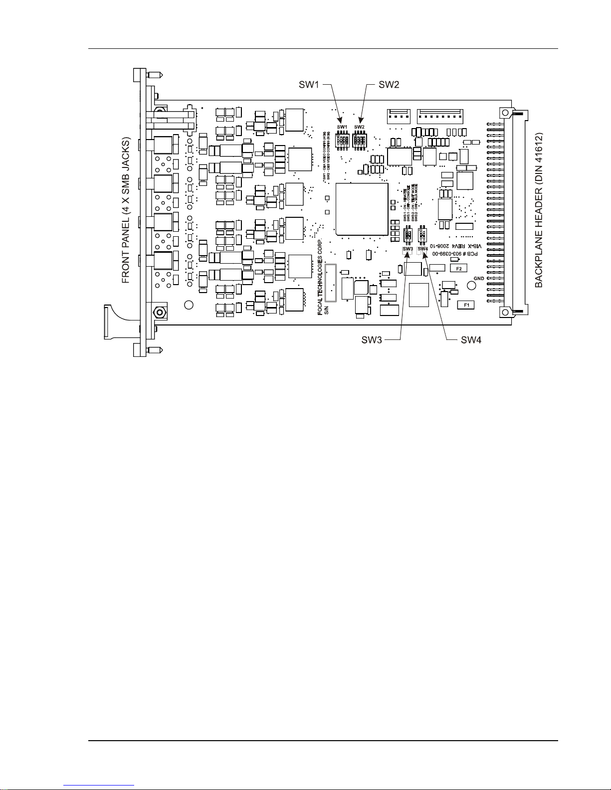
4.1.2 Configuration Settings
The VIB-X is configured as a remote (video input) or console (video output) using switch SW3, as shown
in Figure 4.1-3 and Table 4.1-1. Circuit 1 is used to set the card as video input or output and circuit 2 is
used for setting normal operation (mux mode, default) or for factory test options (test mode).
Table 4.1-1: VIB-X Card Configuration Settings (Switch SW3)
CCT1 CCT2 Description
ON OFF
OFF OFF
ON ON Loop-Test Mode: Ch 1 In to Ch 3 Out; Ch 2 In to Ch 4 Out
OFF ON Loop-Test Mode: Ch 3 In to Ch 1 Out; Ch 4 In to Ch 2 Out
Input and output video formats are configured with switch SW1 per Table 4.1-2. Switch SW2 is not
required for the VIB-TX and VIB-RX configurations of the VIB-X card, and all SW2 circuits should be in
the OFF state. Note that in Y/C modes, “Y” (luma) must be connected to channel 1 to provide sync to “C”
(chroma) on channel 2, and for dual S-video mode, “Y” must be connected to channel 3 to provide sync to
“C” on channel 4. In RGB or YPrPb mode, the sync on “G” or “Y” must be connected to channel 1 to
provide sync to channels 2 and 3. Switch configurations for video format on the remote and console
video cards must match.
Remote Configuration (Video input, e.g. video signal from
camera is connected to this card)
Console Configuration (Video output, e.g. video signal from this
card is connected to a monitor)
Table 4.1-2: VIB-X Input/Output Video Format Configuration (Switch SW1)
CCT1 CCT2 CCT3 CCT4 Description
OFF OFF OFF OFF All Composite ( Channels 1, 2, 3, 4 = Composite)
ON OFF OFF OFF Single S-Video (Channels 1/2 = Y/C, Channels 3, 4 = Comp osite)
OFF ON OFF OFF Dual S-Video (Channels 1/2 = Y/C, Channels 3/4 = Y/C)
ON ON OFF OFF RGB Mode (Channels 1/2/3 = G/R/B, Channel 4 = Composite)
OFF OFF ON OFF YPrPb Mode (Channels 1/2/3 = Y/Pr/Pb, Channel 4 = Composite)
Focal Technologies Corp. Page 4-3
Page 28
903-0623-00 Rev. A Model 903 User's Guide, FMB-X-2.5 Version
Figure 4.1-3: VIB-X Plan View
Fuses on the rails from the backplane provide over-current protection near the 96-pin DIN 41612
connector at the back of the card, per Figure 4.1-3. Fuse F1 is a 3A fuse on the +5 V supply rail and fuse
F2 is a 1A fuse on the -12 V rail, which is used to generate -5 V on the board. These fuses are soldered
in place and are not intended to be field replaceable, as any over-current fault sufficient to blow a fuse
can potentially damage the VIB-X card. Cards with blown backplane fuses should be returned to Focal for
assessment.
The sync status of each video channel is represented by the sync LEDs on the corresponding FMB-X-2.5
modules. Furthermore, for 903 systems that have both the FMB-X-2.5 and backplane -X cards, the
diagnostics software at the surface can monitor the status of the remote VIB-X card, includin g input
voltage overload flags, current video format configuration, and card assembly information, such as serial
number. A black and white bar test pattern is also available on the VIB-X at either the remote or the
console through the diagnostic software (command mode). This test pattern is generated in the FPGA
and at the remote end this test pattern can be output at the front panel as well as to the backplane, and at
the console end the test pattern can be only output to the front panel. Refer to FMB-X-2.5 diagnostics
manual (P/N 903-0622-00) for more details.
Note that VIB-X cards do not support "non-video" signals on channel 4, as with older VIB-TX and
VIB-RX cards. Typically the "non-video" signals were audio or special high speed sonar signals,
which are now handled by other card types. Please consult Focal for any non-standard vi deo
signals or switched video configurations.
Focal Technologies Corp. Page 4-4
Page 29
903-0623-00 Rev. A Model 903 User's Guide, FMB-X-2.5 Version
5.0 Data Cards
Data cards are typically bidirectional, with some exceptions. Most data cards are interchange able
between the remote and console module.
5.1 DIB-232 - RS-232 Interface Board
Card P/N 903-0016-00
The DIB-232 card is obsolete, and this section is for information only. RS-232 channels for ne w
systems can be provided by other cards, such as DIB-232-16, AIB-4 and 907-232E.
The RS-232 Data Interface Boards (DIB-232) support bidirectional RS-232 signals. DIB-232 cards may
be used at either end of the system in any available data slot. RS-232 signals are limited to 120 kbaud.
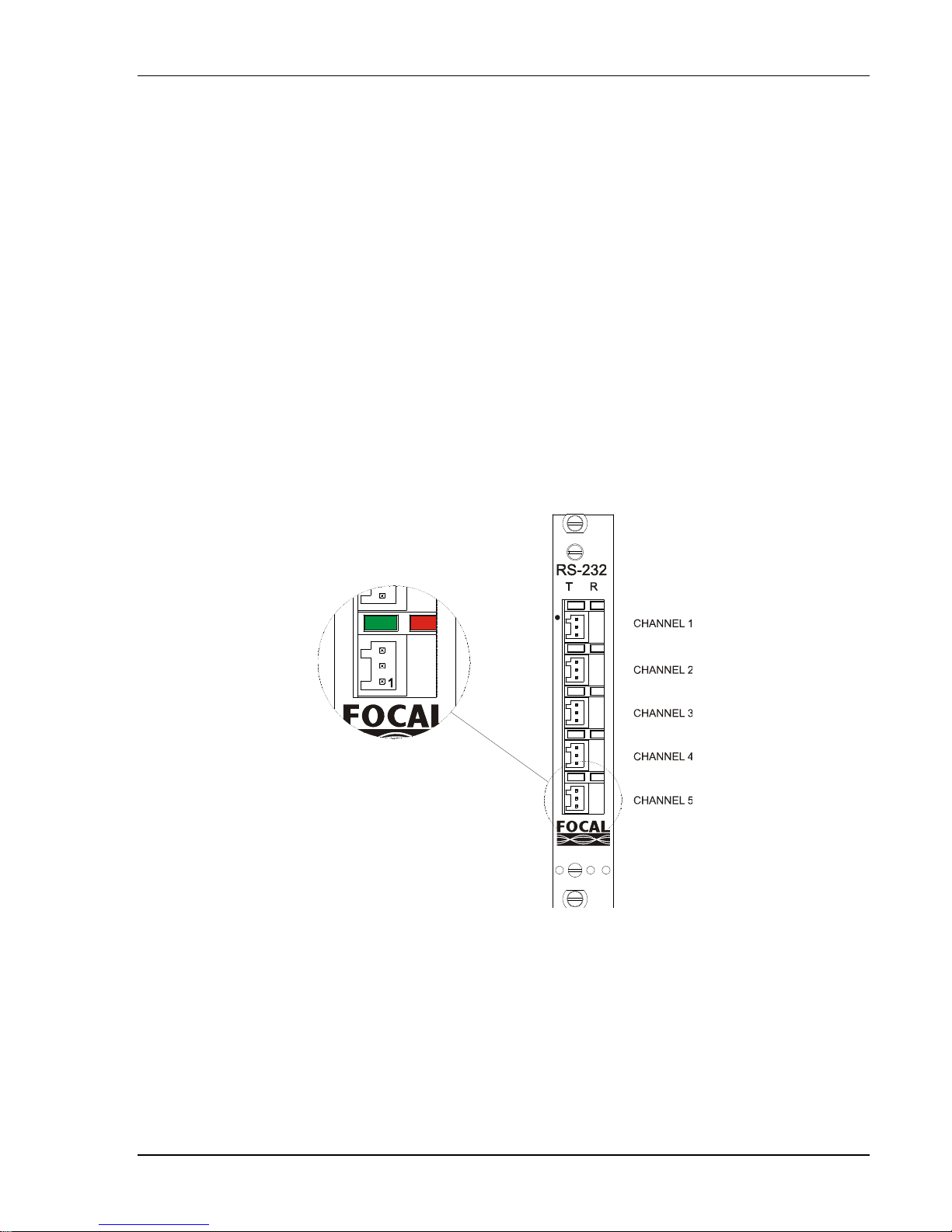
5.1.1 Input/Output
The five front panel connectors, as shown in Figure 5.1-1, are all three pin, right angle, 733 series WAGO
connectors (mate: WAGO 733-103). All five channels are separately isolated and can operate to a
maximum bit rate of 120 kbaud. All channels are protected by 250 mA fuses and transient voltage
suppression diodes. One spare fuse is provided on the board. The black dot at the top of the front panel
marks channel 1.
LED indicators are provided for each DIB-232 channel. T denotes data transmitted out of the DIB board’s
front panel connection as indicated by the green LED. R denotes data received by the DIB-232 board as
indicated by the red LED.
Focal Technologies Corp. Page 5-1
Figure 5.1-1: DIB-232 Front Panel
Page 30
903-
0
l
2
g
p
e
n
gi
n
W
P
t
l
e
W
e
o
5
u
n
e
g
0
h
G
o
n
t
n
e
s
o
C
d
a
G
5
a
h
u
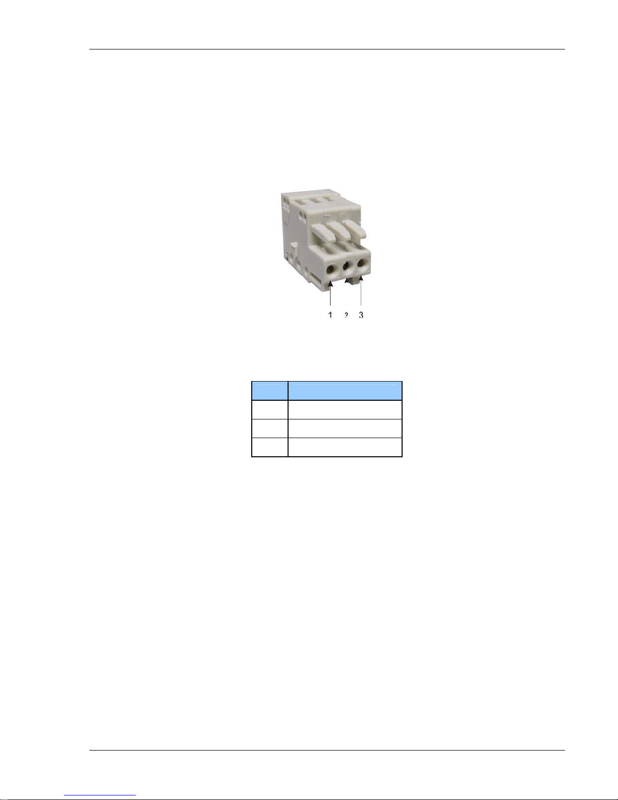
5.1.
Gene
rally, the DIB
confi
The
Figur
curre
623-00 Rev.
Configu
ured for TTL
in-out conve
5.1-2. The
t of 0.25A.
A
ration Set
-232 channe
signals on s
tion for the
AGO conn
in designati
Figure
ings
s do not req
lected chan
AGO conn
ctors should
ns are given
5.1-2: RS-23
ire any confi
els.
ctors (733-1
be used wit
in Table 5.1-
2 3-Pin WA
Model 903
uration setti
3) used for
wire gauge
1.
O Connect
User's Gui
gs. The bo
ach RS-232
20 - 28 AW
r (733-103)
e, FMB-X-2.
rds may be f
channel is s
at a maxim
Version
ctory
own in
m
Table
.1-1: Pin De
Pin
1
2
3
signations f
Desig
Isolated
RXD (Da
TXD (Data
r DIB-232
ation
Ground
a to 903)
from 903)
onnectors
Foca
Technolo
es Corp.
Page 5-2
Page 31

903-0623-00 Rev. A Model 903 User's Guide, FMB-X-2.5 Version
A view of the DIB-232 PCB is given in Figure 5.1-3.
Focal Technologies Corp. Page 5-3
Figure 5.1-3: DIB-232 PCB
Page 32

903-0623-00 Rev. A Model 903 User's Guide, FMB-X-2.5 Version
5.2 DIB-232-16 - High Density RS-232 Card
Card P/N 903-5020-00
The High Density RS-232 card (DIB-232-16) supports sixteen bidirectional channels of RS-23 2 data.
Channels 1-8 are located on the motherboard; channels 9-16 are located on a daughtercard. The front
panel connector is a high density, 62-pin D-subminiature type, as shown below in Figure 5.2-1. Pin
connections are given in Appendix A.
Each channel includes pins for receive, transmit, and isolated ground, where receive data is defined as
coming into the front panel of the Model 903 from an external device. Each channel is fully opto-isolated
from the other channels and the internal digital ground of the Model 903.
Maximum RS-232 NRZ data rate is 115 kbps. Switch S1:1 should be set “off” (open) for correct operation
with FMB-X-2.5 systems, which support high speed sampling on all data ports. Figure 5.2-2 sh ows the
DIB-232-16 motherboard PCBA, including the location of switch S1. If the daughtercard is replaced for
some reason, ensure that the alignment dot on the daughtercard matches the location of the alignment
dot on the motherboard.
Options for breakout boxes and harnesses are available from the factory. For testing, mating pigtail
harness is P/N 903-9002-02.
PIN 42
PIN 21
PIN 62
RS-232
Figure 5.2-1: DIB-232-16 High Density RS-232 Board
Focal Technologies Corp. Page 5-4
PIN 43
PIN 22
PIN 1
Page 33

903-0623-00 Rev. A Model 903 User's Guide, FMB-X-2.5 Version
J1
ALIGNMENT
DOT FOR
DAUGHTERCARD
J5, J10, J11, J12
HEADERS FOR
DAUGHTERCARD
SPEED
SWITCH
S1 = OFF
FOR HIGH
SPEED
Figure 5.2-2: DIB-232-16 Motherboard (Daughtercard Not Shown)
Focal Technologies Corp. Page 5-5
Page 34

903-0623-00 Rev. A Model 903 User's Guide, FMB-X-2.5 Version
C
Figure 5.2-3 shows a block diagram of the DIB-232-16 motherboard; Figure 5.2-4 shows the input/output
schematic for channels 1 and 2. (The other 14 channels are identical.)
J6
KPLANE
LOW SPEED
SIGNALS TO/FROM
BACKPLANE BUFFER
MODE SELECT
S1A
SIGNALS TO/FROM
BACKPLANE
BUFFER
TTL IN CH1 BUFFERED
cPLD FOR
MUX/DEMUX
cPLD FOR
MUX/DEMUX
8 OPTICALLY ISOLATED
RS-232 CHANNELS
TWO
RS-232
IC'S
TWO
RS-232
IC'S
TWO
RS-232
IC'S
TWO
RS-232
IC'S
8
OPTICALLY
ISOLAT E D
RS-232
CHANNELS
J1
FRONT PANEL
62 PIN PCB
CONNECTOR
96 PIN BA
CONNECTOR
CH1_OUT_TO_FP
100nF
CH1_IN_FROM_FP
CH2_IN_FROM_FP
C79
TTL OUT CH1
DAUGHTERCARD
Figure 5.2-3: DIB-232-16 Block Diagram
+5VISO1
C77
100nF
R97
8
3K48R
7
6
5
ISO1
+5VISO1
1
2
3
4
ISO1
+5VISO2
R104
340R
CH2_OUT_TO_FP
U55A
11
T1IN
T1OUT
12 13
R1OUT R1IN
10
T2OUT
T2IN
R2INR2OUT
MAX232EESE
+5V
U54
2
R100
3
340R
14
CH1_232_OUT
CH1_232_IN
7
89
HCPL-0501
+5V
R101
3K48R
+5V
R99
340R
R102
3K48R
U53
2
3
HCPL-0501
U57
8
7
6
5
HCPL-0531
Figure 5.2-4: DIB-232-16 Input/Output Schematic (Channels 1 and 2)
8
7
6
5
R103
340R
ISO2
R98
3K48R
+5VISO2
C78
100nF
ISO2
U56A
11
T1IN
12 13
R1OUT R1IN
10
T2IN
MAX232EESE
T1OUT
T2OUT
R2INR2OUT
14
CH2_232_OUT
CH2_232_IN
7
89
Focal Technologies Corp. Page 5-6
Page 35

903-0623-00 Rev. A Model 903 User's Guide, FMB-X-2.5 Version
5.3 DIB-485 - RS-422/485 Data Interface Board
Card P/N 903-0017-00
The DIB-485 card is obsolete, and this section is for information only. RS-422/485 channels for
new systems can be provided by other cards, such as AIB-4 and 907-485E.
RS-422/485 Data Interface Boards (DIB-485) are compatible with several types of bidirectional RS-422,
RS-485, and TTL signals. The DIB-485 cards are default configured with channels 1, 2 and 3 as RS-485
half duplex (autosense = 9600 baud) and channels 4 and 5 as RS-422. The DIB-485 cards may be
installed at either end of the system in any slots available for data boards.
5.3.1 Input/Output
All lines of the five front panel connectors shown in Figure 5.3-1 are protected by 250 mA fuses and
transient voltage suppression diodes. Channel 1, denoted with a black dot, is slew rate limited, which
minimizes sensitivity to noisy lines while allowing operation at data rates up to 250 kbaud. Channel 1 may
also be configured for compatibility with AC-coupled, or transformer-coupled, RS-485 used by such
devices as Kraft manipulators.
Focal Technologies Corp. Page 5-7
Figure 5.3-1: DIB-485 Front Panel
Page 36

903-
0
l
M
g
A
n
a
g
n
2
1
2
gi
n
a
r
r
a
234
5
R
R
l
h
i
i
o
h
n
a
P
u
4
e
R
i
s
x
h
t
e
u
D
c
A
2
1
p
d
w
L
B
y
i
w
n
4
n
n
s
h
e
A
s
aHa
e
T
n
n
-
/
-
A
d
a
s
a
e
e
2
O
W
o
p
d
n
n
nPin
5
o
h
s
m
O
U
D
623-00 Rev.
Chan
nels 2 throug
2.5
baud. Chan
duple
x RS-422 ch
confi
ll ch
annels have
chan
right
733-1
04), and the
confi
in Fig
ure 5.3-2. Th
curre
ured for TTL
el and the g
ngle 733 se
urations are
t of 0.25A.
A
h 5 are not s
els 1, 2, and
nnels, whic
.
LEDs indicat
een LED ind
ies WAGO c
half duplex c
given in Tabl
e WAGO co
T
ew rate limit
3 are 2-wire
can be conf
ng data tran
cates data e
nnectors. T
annels use
e 5.3-1. A vi
nectors sho
ble 5.3-1:
d and can o
S-485 half
gured as 2-
fer: the red
iting the DI
e full duplex
he two pin t
w of the mat
ld be used
IB-485 Cha
Model 903
erate at asy
uplex chann
ire RS-485 c
ED indicate
channel at t
channels us
pe (mate: W
ing 2-pin and
ith wire gaug
nel Configu
User's Gui
chronous d
els; channel
hannels. Ch
data being r
e front pane
4 pin conn
GO 733-10
4-pin WAG
es 20 - 28 A
ration
e, FMB-X-2.
ta rates up t
4 and 5 are
nnel 5 can a
ceived by t
l. Connector
ctors (mate:
). Channel
connectors
G at maxi
Version
4-wire full
lso be
e DIB
are all
WAGO
is given
um
Ch
nnel
1
Fig
CB Conne
Designato
J1
J2
J3
J4
J5
re 5.3-2: W
tor
r
GO RS-422/
De
Half-duplex,
H
Full-dupl
Full-duplex,
85 data co
cription
DC or AC c
lf-duplex
lf-duplex
x or Half-du
TTL or Half-
nectors
upled
lex
uplex
-Wire (733-1
Pin
= A +Tx/+
Pin
= B -Tx/-
02)
x
x
Foca
Technolo
es Corp.
Table 5.3-
-Wire (733-
Pin
1 = A +Rx
Pin
2 = B -Rx
Pin
3 = Y +Tx
Pin
4 = Z -Tx
RS-422
: WAGO Pi
04)
Pin
Pin
Pin
Pin
Designatio
4-Wire (733
RS-485
1 = A +Tx
2 = B -Tx/
3 = N/A
4 = N/
ns
104)
+Rx
Rx
4-Wire (733
TTL (CH5
Pi
1 = INPUT
Pi
2 = N/C
Pi
3 = OUTP
4 = ISOGN
-104)
nly)
T
5
Page 5-8
Page 37

903-0623-00 Rev. A Model 903 User's Guide, FMB-X-2.5 Version
5.3.2 Configuration Settings
Channels 1-3 have the following possible settings: RS-485 autosense (half duplex), RS-485 unidirectional
transmitter (simplex Tx), and RS-485 unidirectional receiver (simplex Rx). Channels 4 and 5 additionally
have the option for RS-422 (full duplex, four-wire connection) and Channel 5 ha s the option for full duplex
TTL. Configuration settings for the switches and jumpers are shown in Table 5.5-3. For DIP switches, a
"1" indicates a switch is "on" or "closed" and a "0" indicates a switch is "off" or "open". For 2-pin jumpers,
a "shunt" indicates the pins are connected with a shorting terminal and "open" indicates the shorting
terminal is removed. For 3-pin jumpers, the table entry indicates which pins are shorted together.
The RS-485 autosense mode uses a timer circuit to automatically switch from transmit to receive mode.
By default, a channel in autosense mode is a receiver waiting for data to come in through the front panel
and switches to a transmitter when it gets data from the backplane. Once the RS-485 channel is in
transmitter mode, it will wait ten bit times (one start bit, eight data bits and one stop bit) from the last
positive data edge before reverting back to its default receiver state.
This half-duplex mode operates in a ping-pong fashion that must be supported by the end equipment.
Although the circuit can sense data at a certain data rate and be either a receiver or a transmitter, the
data being passed must be sent or received under timing conditions that inherently avoid collisions. (If a
data collision does occur, transmission out of the front panel connector will override incoming data.)
Autosense settings only affect half-duplex operation. Default settings for the autosense timer (9600 baud)
are appropriate for most sonars, even when the sonar is operating at higher baud rates, since delays
between sonar send and receive are typically many milliseconds.
A channel configured in simplex Tx or simplex Rx is a two-wire interface that is only designated to
transmit or receive data. Tx is defined as Model 903 transmitting data out the front panel whereas Rx is
defined as the Model 903 channel receiving data from an external device.
Focal Technologies Corp. Page 5-9
Page 38

903-0623-00 Rev. A Model 903 User's Guide, FMB-X-2.5 Version
Table 5.3-3: DIB-485 Configuration Settings (Defaults Shaded)
CHANNELS 1, 2 and 3 MODE CONFIGURATION
CHANNEL 1 CHANNEL 2 CHANNEL 3
FUNCTION
JP1 JP2 JP3, JP4, JP5 JP6 JP7 JP8 JP9
RS-485 Half Duplex
(Autosense)
2-3 2-3 SHUNT 2-3 2-3 2-3 2-3
RS-485 Simplex Tx 1-2 1-2 SHUNT 1-2 1-2 1-2 1-2
RS-485 Simplex Rx OPEN OPEN SHUNT OPEN OPEN OPEN OPEN
Kraft (AC RS-485) 2-3 2-3 OPEN Not Applicable
CHANNEL 4 MODE CONFIGURATION
FUNCTION JP10 JP11 JP12 JP13 JP14
RS-485 Half Duplex
(Autosense)
RS-485 Simplex Tx 1-2 1-2 OPEN SHUNT SHUNT
2-3 2-3 OPEN SHUNT SHUNT
RS-485 Simplex Rx OPEN OPEN OPEN SHUNT SHUNT
RS-422 Full Duplex OPEN 1-2 SHUNT OPEN OPEN
CHANNEL 5 MODE CONFIGURATION
FUNCTION JP15 JP16 JP17 JP18 JP19 JP20 JP21
RS-485 Half Duplex
(Autosense)
2-3 2-3 OPEN SHUNT SHUNT 1-2 2-3
RS-485 Simplex Tx 1-2 1-2 OPEN SHUNT SHUNT 1-2 2-3
RS-485 Simplex Rx OPEN OPEN OPEN SHUNT SHUNT 1-2 2-3
RS-422 Full Duplex OPEN 1-2 SHUNT OPEN OPEN 1-2 2-3
TTL Full Duplex OPEN 1-2 OPEN OPEN OPEN 2-3 1-2
AUTOSENSE BAUD RATE FOR SW1, SW2, SW3, SW4, SW5 DIP SWITCHES
(SW1 = CH1, SW2 = CH2, SW3 = CH3, SW4 = CH4, SW5 = CH5)
BAUD RATE CCT# 1 2 3 4 5 6 7 8
9600 1 0 0 0 0 0 1 0
19200 0 1 0 0 0 0 1 0
28800 0 0 1 0 0 0 1 0
57600 0 0 0 1 0 0 1 0
115.2K 0 0 0 0 1 0 0 1
230.4K
KRAFT (CH 1 only) 0 0 0 1 0 0 0 1
1 = ON = CLOSED, 0 = OFF = OPEN
Focal Technologies Corp. Page 5-10
0 0 0 0 0 1 0 1
Page 39

903-0623-00 Rev. A Model 903 User's Guide, FMB-X-2.5 Version
JP22 and JP23 should remain shunted at all times. JP24 should have pins 1-2 shunted at all times.
JP25 is a spare shunt.
Focal Technologies Corp. Page 5-11
Figure 5.3-3: DIB-485 PCBA
Page 40

903-0623-00 Rev. A Model 903 User's Guide, FMB-X-2.5 Version
5.4 CIB-10 Control Interface Board
Card P/N 903-5040-XX
The CIB-10 control interface board, as shown in Figure 5.4-1 below, provides 10 bidirectional
independent control lines, also known as TOR (tout ou rien) channels. Each TOR input controls the
corresponding output at the other end of the system. When the input is "on", the output solid state relay
acts like a closed switch for a maximum of 24 VDC and 100 mA. When the input is "off", the output is in
an open state.
TOR inputs are of two types: type 1 accepts voltage inputs (24 V = logic 1 = on; 0 V = logic 0 = off), type 2
inputs are self-powered, requiring a closed switch to turn "on" the corresponding output. Inputs are
passed through opto-couplers; outputs are passed through photo-MOS "relays". Each input may be
switch configured for Type 1 (voltage input) or Type 2 (switch input). Type 2 inputs share the same +5V
isolated supply to drive the opto-couplers. All TOR outputs have completely isolated pins.
HD-22
PIN
44
PIN
31
PIN 30
PIN 16
PIN
15
PIN 1
Focal Technologies Corp. Page 5-12
Figure 5.4-1: CIB-10 Front Panel
Page 41

903-0623-00 Rev. A Model 903 User's Guide, FMB-X-2.5 Version
1
)
Schematics for channel 1 TOR input and output are shown in Figure 5.4-2, with the Type 1 (both dual
switches open) shown. The other TOR channels are identical, where chann el 2 input is configured by
switches SW3 and SW4, channel 3 input is configured by switches SW5 and SW6, etc. Both switches
must be “open” (off) for Type 1 and “closed” (on) for Type 2 configuration. Note that SW2, SW4, SW6...
SW20 are single pole double throw (SPDT) switches with no common, where circuit 1 is “open” and
circuit 2 is “closed”, or vice versa. Setting SW2, for example, to “open” refers to circuit 1 being open.
Figure 5.4-2 shows SW1 and SW2 both “open” (off).
TOR inputs are polled at regular intervals by a microcontroller and encoded in a frame on a single
9600 baud data stream, which is sampled by the Model 903 multiplexer. The microcontroller at the other
end of the system reads the demultiplexed 9600 baud data stream and sets the TOR outputs according to
the encoded bits. Latency is less than 5 milliseconds.
Any time the Model 903 optical data link is lost, including initial start up, the TOR outputs are all set to the
open state until the link is restored. If the receiving microcontroller detects errors in the frame, the outputs
are set to open until an error-free frame is received.
Opto-couplers on the TOR inputs invert the incoming signal. This is compensated for by the
microcontroller program, which translates low TTL inputs to high TTL outputs for the remainder of the
Model 903 system.
TOR INPUT (TYPE 1 OR 2
+IN1
-IN1
OUT_TOR1
R3
2K21
SW2
1 4
78HJ01GW
SW1
1 4
32
78HF01GW
ISOGND3
32
R1
150R
R4
270R
D1
BZX84C4V7
R5 150R
+5VISO3
D2
LL4148
TOR OUTPUT
R51 OPEN
U13A
1 2
MC74HC04AD
R53
0R 5%
U13B
3 4
MC74HC04AD
R54
698R
Figure 5.4-2: CIB-10 TOR Input and Output
+5V
C1
U1
2
3
HCPL-0501
87
K1A
8
6
5
R57 0R 5%AQW212A
R2
3K48R
-OUT1
+OUT1
0u1F
IN_TOR
Focal Technologies Corp. Page 5-13
Page 42

903-
0
l
e
gi
s
B
r
i
-
u
d
5
P
Figur
623-00 Rev.
5.4-3 show
A
a view of the CIB-10 PC
A with locat
Model 903
ion of config
User's Gui
ration switch
e, FMB-X-2.
es.
Version
Foca
Technolo
es Corp.
Figu
e 5.4-3: CIB
10 PCBA
age 5-14
Page 43

903-0623-00 Rev. A Model 903 User's Guide, FMB-X-2.5 Version
C
E
O
R
SOGND3
J1C
Figure 5.4-4 below shows a block diagram of the CIB-10 board.
FRONT PANEL
HD 62-PIN
T
INPUTS/
D TYPE
OUTPUTS
Ch1 - 10 SWITCHABLE
TYPE1 OR TYPE 2
TOR INPUTS
Ch1 - 10
TOR OUTPUTS
ISOLATED
POWER3
OPTOCOUPLERS
WITH INPUT
PROTECTION
PHOTOMOS
RELAYS
ISOLATION
BARRIER
10 DIGITAL
INPUTS
10 DIGITAL
OUTPUTS
CIB-10
MICROCONTROLLER
TOR INPUT S
TOR OUTPUTS
BUFFERS
+5V
-12V
EMI & FUSE
PROTECTION
BA
KPLAN
Figure 5.4-4: CIB-10 Block Diagram
Two pins are provided for shield connections: TOR In Shield = pin 41; TOR Out Shield = pin 42. Both of
these pins may each be shorted directly to chassis ground or ISOGND3, which is the common gro und for
Type 2 inputs. The default configuration is with all shield switches open, as shown in Figure 5.4-5.
31
32
33
34
35
36
37
38
39
40
41
42
43
44
748482-5
+OUT6
-OUT6
+OUT7
-OUT7
+OUT8
-OUT8
+OUT9
-OUT9
+OUT10
-OUT10
TOR OUT S HIELD
TOR IN SHIELD
SW22A
1 4
GDH02S
SW22B
2 3
GDH02S
I
Figure 5.4-5: CIB-10 Shield Options
Pin designations for the front panel 44-pin connector are given in Appendix A.
SW21A
1 4
GDH02S
SW21B
2 3
GDH02S
ISOGND3
Focal Technologies Corp. Page 5-15
Page 44

903-0623-00 Rev. A Model 903 User's Guide, FMB-X-2.5 Version
K
K
X
5.5 EIB-10/100 Ethernet Board (Electrical Version)
Card P/N 903-5044-00
The EIB-10/100 Ethernet Interface Board provides three RJ-45 ports of 10Base-T (10 Mbps) or
100Base-TX (100 Mbps) Ethernet inputs to an internal switching hub (switch). Each port auto-negotiates
the data rate and duplex mode of the input.
The EIB-10/100 Ethernet Board is available in two versions, one is electrical and the other is optical. This
section provides information about the electrical version of the EIB-10/100. For information about the
optical version of the card, refer to section 6.2. A front panel view of the card in Figure 5.5-1 shows pin
and LED locations on the RJ-45 jacks.
Unlike simple repeating hubs, which copy all incoming packets on one port to all other ports, switching
hubs have the ability to store and forward packets while controlling the flow of packets through each port
independently. Unicast packets are forwarded to only one port, greatly improving network efficiency.
The EIB-10/100 card (electrical version) must be installed in a high speed data sl ot. All data slots on -X
backplanes are high speed. On older systems only data slot 1 is high speed (typically data slot 1 is
identified with the letter D in the installation drawings 903-8XXX-XX). Although the front panel RJ-45 ports
are compatible with both 10 and 100 Mbps traffic, the backplane link operates solely in a full-duplex,
10Base-T compatible mode, which is linked to the opposite end of the multiplexer system via the FMB
optical link. The electrical version of the EIB-10/100 cards may be operated over 10 km or more of optical
fiber, albeit with the throughput of a full-duplex, 10 Mbps Ethernet link.
GREEN LED
OFF = NO LIN
ON = LIN
FLASHING = ACTIVITY
PIN 1
PIN 8
AMBER LED
OFF = HALF-DUPLEX, NO COLLISION
ON = FULL DUPLE
FLASHING = COLLISION
Figure 5.5-1: EIB-10/100 Front Panel
EIB-10/100
Focal Technologies Corp. Page 5-16
Page 45

903-0623-00 Rev. A Model 903 User's Guide, FMB-X-2.5 Version
5.5.1 Input/Output
The three ports on the front panel accept industry standard RJ-45 UTP (Unshielded Twi sted Pair) or STP
(Shielded Twisted Pair) Cat 5e cables wired per EIA/TIA-568. All of the twisted pair ports are transformercoupled to the internal switching hub, which has additional on-board filtering. Packets sent into one of the
front panel ports will be routed by the switch only to the port associated with the matching MAC address,
be it on one of the local ports or one of the ports at the other end of the system. (Broadcast and multi-cast
packets are sent to all ports.) An internal 64 KB buffer is shared among all of the ports for storing and
forwarding packets.
All front panel RJ-45 ports have auto-MDI/MDI-X configuration so that the jacks may be used with either
"straight through" cables (wired to EIA/TIA-568B on both ends) or "cross-over cables (wired to
EIA/TIA-568A on one end and EIA/TIA-568B on the other end). Auto-negotiation and auto-MDI/MDIX
configuration are activated each time a new link is being established between the EIB-10/100 port and the
external device, for example after power up or after changing a cable.
The pin assignments of the RJ-45 jacks are summarized in Table 5.1-1. Typically, the switch port should
be in MDI configuration for connection to NICs (network interface cards) and in MDI-X configuration for
connection to other repeating hubs and switches.
Table 5.5-1: RJ-45 Pin Assignments
RJ-45 Contact MDI-X MDI
1
2
3
4
5
6
7
8
TXD+ RXD+
TXD- RXD-
RXD+ TXD+
Unused Unused
Unused Unused
RXD- TXDUnused Unused
Unused Unused
LED Description
Green
(RJ-45)
The green LED on each RJ-45 jack is on when there is a link pulse present, indicating
an external device is connected with a valid Ethernet link. The green LED flashes
during packet transfers.
The amber LED on each RJ-45 jack is on if the link is full duplex and off if the link is
Amber
(RJ-45)
half duplex. When operating in half-duplex mode, the LED flashes when there is a
collision. Normally the amber LEDs should be on at all times when the external
equipment supports full-duplex operation. Some equipment, such as web cameras
and older Ethernet gear, do not support full-duplex operation.
The T and R LEDs at the bottom of the panel indicate traffic through a fourth port on
T and R
(Bottom
Panel)
the switching hub connected to the backplane. The green TX LED indicates data
traffic arriving from the backplane and leaving the front panel, and the red RX LED
indicates data traffic coming in the front panel and being sent to the backplane.
The T and R LEDs are off when the optical version of the EIB-10/100 card is used.
Focal Technologies Corp. Page 5-17
Table 5.5-2: EIB-10/100 Front Panel LEDs
Page 46

903-0623-00 Rev. A Model 903 User's Guide, FMB-X-2.5 Version
5.5.2 Configuration Settings
Internal connections of the RJ-45 PCB jack are shown below in Figure 5.5-2. Inside each jack, RJ-45 pins
4, 5, 7, 8 are connected through 75 ohm resistors and a capacitor to a voltage reference (E_GND) on pin
8 of the PCBA header. (All three jacks share the same E_GND reference.) Switch S8 on the board allows
E_GND to be shorted to either chassis ground (default), through the front panel, or REFEL. Similarly,
case pins 13 and 14 on all jacks are connected to a common shield reference that may be shorted to
either chassis or REFEL with switch S9. If the external RJ-45 connector is shielded, the cable shield will
contact the case of the RJ-45 socket. REFEL is a special voltage reference only available on custom
backplanes and typically not used in most systems.
Figure 5.5-2: EIB-10/100 RJ-45 Grounding Options
Note: EIB-10/100 PCBA (Rev. 2) shows the ground/shield switches as S8 and S9 respectively and
EIB-10/100 PCBA (Rev. 1) shows the ground/shield switches as S5 and S6 respectively.
Focal Technologies Corp. Page 5-18
Page 47

903-0623-00 Rev. A Model 903 User's Guide, FMB-X-2.5 Version
A view of the EIB-10/100 PCBA is given in Figure 5.5-3. Although many configurations are available for
the switching hub chip, the default settings from the factory should normally be used.
BACKPLANE
GROUND/SHIELD
SWITCHES (S8, S9)
SWITCHING HUB
CONFIG. PORT J3
(FACTORY USE ONLY)
OPTICAL
TRANSCEIVER
STATUS LEDS
3 X RJ-45 PORTS
CONFIGURATION
SWITCHES (S1, S2, S3)
* NOTE ORDER ON PCB
IS S1, S3, S2, AS SHOWN
OPTICAL BUSHING
BRACKET
STANDALONE
POWER HEADER
PIN 1 = +5V
PIN 2 = GND
(OPTICAL VERSION
ONLY)
U16
Figure 5.5-3: EIB-10/100 PCBA
PLD PROGRAMMING
PORT J2
(FACTORY USE ONLY)
OPTICAL/ELECTRICAL
CONFIG. JUMPER
JP1 = SHUNT = ELECTRICAL
JP1 = OPEN = OPTICAL
Focal Technologies Corp. Page 5-19
Page 48

903-0623-00 Rev. A Model 903 User's Guide, FMB-X-2.5 Version
Table 5.5-3 shows the settings for auto-negotiate or forced protocol. Auto-negotiate automatically
configures the data rate and duplex mode of the port to match the external device connected and typically
occurs within a few seconds after making a connection. Each port may be independently forced to one of
the configurations listed.
In most applications, the EIB-10/100 port and external device port should be either both set to
auto-negotiation or both forced to the same speed and duplex configuration. In cases where the device at
one end of the link is forced and the other auto-negotiates, the link may configure itself with a duplex
mismatch that causes moderate to severe degradation of the packet throughput. Moreover, older
10Base-T and 100Base-TX equipment may be incompatible with auto-negotiation altogether. In these
cases, the EIB-10/100 port should be forced to match the external device. Switch-to-switch connections
often work better when both ends of the link use forced configurations.
Table 5.5-3: RJ-45 Individual Port Settings
Port Configuration
Auto-Negotiate (default)
10Base-T Half Duplex
10Base-T Full Duplex
100Base-TX Half Duplex
100Base-TX Full Duplex
S1:1 S2:1 S3:1 S1:2 S2:2 S3:2 S1:3 S2:3 S3:3
Port 1 Port 2 Port 3
1 X X 1 X X 1 X X
0 1 1 0 1 1 0 1 1
0 1 0 0 1 0 0 1 0
0 0 1 0 0 1 0 0 1
0 0 0 0 0 0 0 0 0
1 = ON = CLOSED, 0 = OFF = OPEN, X = DON'T CARE
Table 5.5-4 shows additional global settings that may be switch configured. These settings apply to all
ports simultaneously.
Table 5.5-4: Global Port Settings
Parameter Switch Settings
Flow Control
Broadcast Protection
Backwards Compatibility
RJ-45 Port Grounding
S1:4 1 = DISABLED, 0 = ENABLED (DEFAULT)
S2:4 1 = DISABLED, 0 = ENABLED (DEFAULT)
S3:4 1 = ENABLED, 0 = DISABLED (DEFAULT)
S8 1 = REFEL (REF. GND), 0 = CHASSIS (DEFAULT)
RJ-45 Shield Grounding
1 = ON = CLOSED, 0 = OFF = OPEN
Flow control is normally enabled. This feature applies "back pressure" to the port if buffers are nearing
100% use to avoid a buffer overflow and subsequent loss of packets. Such a situation usually only arises
during peak traffic periods or when a 100 Mbps device is connected to the EIB-10/100 (elect rical version)
card, which is limited to 10 Mbps through the multiplexer.
Broadcast protection is normally enabled. Broadcast and multicast packets are normally forwarded to all
switch ports other than the originating port. With broadcast protection enabled, the switch will d i scard
broadcast or multicast packets if the number of those packets exceeds a threshold of 25% of the network
line rate, thereby minimizing "broadcast storms". Broadcast protect should be disabled if the given
application requires more than 25% broadcast packets.
Backwards compatibility is normally disabled. This feature allows the electrical version of the EIB-10/100
to be used with the older EIB-10BT cards. When enabled, backwards compatibi lity forces the EIB-10/100
backplane Ethernet link into a 10 Mbps half-duplex mode. This limits performance to a similar level as the
EIB-10BT card, which has a limit of 2 km on the optical fiber link.
Focal Technologies Corp. Page 5-20
S9 1 = REFEL (REF. GND), 0 = CHASSIS (DEFAULT)
Page 49

903-0623-00 Rev. A Model 903 User's Guide, FMB-X-2.5 Version
5.5.3 Flow Control
The internal switching hub is a "learning switch" that monitors incoming packets to identify the MAC
addresses of the sources and establish a dynamic look-up table of up to 1024 addresses. Initially this
table is empty. Each time the switch receives a valid packet with a source MAC address not currently in
the look-up table, the source address is added to the table along with a time stamp. If the destination
MAC address is not in the look-up table, the packet is regenerated and forwarded to all other ports. Once
the destination MAC address is established in the look-up table, namely by receiving a packet from that
device, packets sent to that address will be regenerated only on the port identified in the look-up table.
Depending on traffic patterns, the switch typically learns all of the MAC addresses within a few seconds,
though it may take longer to identify stations that do not generate much traffic. During the learning period,
many packets will be copied to all ports.
If no packets are received from a given MAC address for 375 seconds, the aging feature of the switch
removes the look-up table entry. If an external device is moved from one port to another on the same
EIB-10/100 card, the migration feature of the switch immediately updates the table as soon as a new
packet is received. If, however, an external device is moved from the switch at one end of the system to
the switch at the other end, it may take up to the aging time (375 seconds) before the link through the
multiplexer is properly re-established. Consider this behaviour when switching cables around during
bench tests.
The switch will not forward the following types of packets:
Error packets due to framing errors, FCS errors, alignment errors, and illegal size frames
802.3x pause frames
"Local" packets. Packets are deemed "local" if the destination address from the look-up table
matches the port of the incoming packet, e.g. from old repeating hubs
Broadcast or multicast packets that exceed the threshold when broadcast protection is enabled
Focal Technologies Corp. Page 5-21
Page 50

903-0623-00 Rev. A Model 903 User's Guide, FMB-X-2.5 Version
5.6 AIB-4 - Adaptable Interface Board
Card P/N 903-5003-00
The Adaptable (or Analog) Interface Board (AIB-4) provides four generic channels of data with four
sockets that may be populated with any mixture of available plug-in modules. These include analog
interfaces for hydrophones, sonars (MS900), and sensors, in addition to digital interfaces, such as
RS-232, RS-485/422/TTL, and Tritech sonar ARCNET. Figure 5.6-1 below shows the location of pin 1 on
the WAGO connectors when viewed from the front panel. Channel 1 is at the top of the column of
connectors, as marked by the black dot along the left-hand side of the panel.
LED indicators display presence of data on the transmit and receive line for each channel. In general, the
green LEDs under the “T” column are on when data is transmitted from the front panel of the AIB card.
The red LEDs under the “R” column are on when data is being received into the AIB front panel from an
external source. For serial data interfaces, LEDs are on when the corresponding line is in a “space” state
(TTL = low) and off when the line is in a “mark” state (TTL = high). Idle lines are typically in the “mark”
state. If an AIB socket is not populated, both LEDs will be on.
During unidirectional data transfer, an active red LED at one end of the system should be matched by an
active green LED at the other end of the system. For example, what is received at the remote module
should be transmitted by the console module.
Figure 5.6-1: Adaptable Interface Board (AIB-4) Front Panel
Focal Technologies Corp. Page 5-22
Page 51

903-0623-00 Rev. A Model 903 User's Guide, FMB-X-2.5 Version
Figure 5.6-2 shows the AIB motherboard, and Figure 5.6-3 shows the block diagram for the AIB
motherboard.
J10
J17 J12
ALIGNMENT
DOTS (X4)
J16
J14
J11
J9
Figure 5.6-2: Adaptable Interface Board (AIB-4) PCB
Focal Technologies Corp. Page 5-23
Page 52

903-0623-00 Rev. A Model 903 User's Guide, FMB-X-2.5 Version
CHANNEL 4
USE J5
CHANNEL 1
USE J2 WAGO
CONNECTOR
HEADERS FOR
PLUG-IN MODULES
CHANNEL 3
USE J4
CHANNEL 2
USE J3
CONNECTOR
CONNECTOR
CONNECTOR
96-PIN RIGHT ANGLED
BACKPLANE CONNECTOR
Figure 5.6-3: Block Diagram of Adaptable Interface Board (AIB-4)
Focal Technologies Corp. Page 5-24
J6
SIGNALS TO/FROM
BACKPLANE BUFFER
+5V
DGND
+12V
-12V
AGND
Page 53

903-0623-00 Rev. A Model 903 User's Guide, FMB-X-2.5 Version
5.6.1 Plug-In Modules
A variety of plug in modules is available for use with the AIB-4 cards. When installing the modules, ensure
the connector marked by the white dot on the module PCB is mated with the corresponding header
marked with a white dot on the AIB motherboard. When removing the modules, carefully extract the
plug-in board by pulling both connectors straight out to minimize flexing of the PCB. Uninstalled AIB
modules should be handled like integrated circuits: observe ESD handling precautions and store in static
dissipating bags or conductive foam.
The following table shows a summary of the AIB plug-in modules available.
Table 5.6-1: AIB Plug-in Modules
Card ID Card Description Card P/N
AIB-232 RS-232 Plug-In 903-0251-00
AIB-TRIGGER Responder Trigger Plug-In 903-0251-01
AIB-485 RS-485/422/TTL Plug-In 903-0252-00
AIB-ARCNET Tritech Sonar ARCNET Plug-In 903-0261-00
AIB-HYDRO Hydrophone/Analog Plug-In 903-0244-00
AIB-MS900 MS-900 Analog Sonar Plug-In 903-0250-00
AIB-CANBUS CANBUS Plug-In 903-0297-00
5.6.2 RS-232 Plug-In (AIB-232/TRIGGER)
Card P/N 903-0251-00 (AIB-232)
Card P/N 903-0251-01 (AIB-TRIGGER)
The AIB-232 plug-in module, which supports RS-232, is shown below in Figure 5.6-4. No jump er or switch
settings are required since the board is used solely for RS-232 data to a maximum of 120 kbaud. In
addition to the ultra-fast fuses on the AIB-4 motherboard, protection for RS-232 inputs and outputs
includes transient voltage suppressors and opto-isolation.
Figure 5.6-4: AIB RS-232/TRIGGER Plug-In Module
Connector pin designations for the front panel WAGO connector are given in t he table below. ISOGND is
the common isolated signal ground for both receive and transmit data. Front panel LEDs can be used to
identify the presence and direction of serial data.
*The chassis pin is normally left open on the mating connector.
Note: The AIB-TRIGGER plug-in module is identical to the AIB-232 plug-in module except that the
transmit pin 3 is not RS-232 compatible; instead this pin is a 0V to +5V TTL output.
Focal Technologies Corp. Page 5-25
Table 5.6-2: AIB-232/TRIGGER Pin Designations
Pin Designation
1 ISOGND
2 Receive (RXD)
3 Transmit (TXD)
4 Chassis* (optional)
Page 54

903-0623-00 Rev. A Model 903 User's Guide, FMB-X-2.5 Version
S
5.6.3 RS-485/422/TTL Plug-In (AIB-485)
Card P/N 903-0252-00
The AIB-485 plug-in module, which supports RS-485, RS-422, and TTL, is shown below in Figure 5.6-5.
In addition to the ultra-fast fuses on the AIB-4 motherboard, protection for RS-485/422/TTL inputs and
outputs includes transient voltage suppressors and opto-isolation.
SW5
SW2
SW3
W4
Figure 5.6-5: AIB RS-485 Plug-In Module
Each channel has the following possible settings: RS-485 autosense (half duplex), RS-485 unidirectional
transmitter (simplex Tx), RS-485 unidirectional receiver (simplex Rx), RS-422 four-wire connection (full
duplex), or TTL (full duplex).
The equivalent input/output schematic for an RS-422 configuration is shown in F igure 5.6-6, based on
default switch settings. The switches are not shown for clarity. AIB-485 plug-in modules are default
configured for RS-485, in which case the transmit and receive circuits of the RS-422 driver IC are
connected together.
The RS-485 autosense mode uses a timer circuit to automatically switch from transmit to receive mode.
By default, a channel in autosense mode is a receiver waiting for data to come in through the front panel
and switches to a transmitter only when it receives data from the backplane. Once the RS-485 channel is
in transmitter mode, it will wait ten bit times (one start bit, eight data bits and one stop bit) from the last
positive data edge before reverting back to its default receiver state.
This half-duplex mode operates in a ping-pong fashion that must be supported by the end equipment.
Although the circuit can act as either a receiver or a transmitter, the data being passed must be sent or
received under timing conditions that allow for collision-free data transmission. (If a data collision does
occur, transmission out of the front panel connector will override incoming data.) Autosense settings only
affect half-duplex operation.
Default settings for the autosense timer (9600 baud) are appropriate for most sonars, even when the
sonar is operating at higher baud rates, since delays between sonar send and receive are generally many
milliseconds. In some cases, though, the autosense timer needs to be adjusted base d on the absolute
turnaround time of the external device.
A channel configured in simplex Tx or simplex Rx is a two-wire interface that is only designated to
transmit or receive data. Tx is defined as Model 903 transmitting data out the front panel whereas Rx is
defined as the Model 903 channel receiving data from an external device.
SW1
Focal Technologies Corp. Page 5-26
Page 55

903-0623-00 Rev. A Model 903 User's Guide, FMB-X-2.5 Version
Figure 5.6-6: AIB RS-422 Interface Schematic
Full duplex communication runs transmit and receive on separate conductors, thus autosense is not
required. The AIB modules support full duplex transmission as either RS-422 or TTL data.
Connector pin designations for the front panel WAGO connectors are given in the table below with defa ult
configuration shaded.
Table 5.6-3: AIB-485 Pin Designations
Pin RS-485 Designation RS-4 22 Designation TTL Designation
1 TX+/RX+ RX+ TTL IN
2 TX-/RX- RX- N/C
3 N/C TX+ TTL OUT
4 N/C TX- ISOGND
Switch settings for the various configurations are given in Table 5.6-4. When using the module in RS-422
or TTL input configuration, the autosense mode (SW3, SW4) should be set for full-duplex operation.
Autosense baud rate settings (SW5) are ignored when the module is in full-du plex or simplex modes.
Focal Technologies Corp. Page 5-27
Page 56

903-0623-00 Rev. A Model 903 User's Guide, FMB-X-2.5 Version
Table 5.6-4: Configuration Settings for AIB RS-485 Module (Defaults Shaded)
AUTOSENSE MODE CONFIGURATION
FUNCTION SW3:1 SW3:2 SW4:1 SW4:2
Full Duplex 0 0 1 0
Simplex Tx 1 0 1 0
Half Duplex
(Autosense)
0 1 0 1
Simplex Rx 0 0 0 0
AUTOSENSE BAUD RATE FOR SW5 DIP SWITCH
BAUD RATE CCT# 1 2 3 4 5 6 7 8
9600 1 0 0 0 0 0 1 0
19200 0 1 0 0 0 0 1 0
28800 0 0 1 0 0 0 1 0
57600 0 0 0 1 0 0 1 0
115.2K 0 0 0 0 1 0 0 1
230.4K
0 0 0 0 0 1 0 1
KRAFT* 0 0 0 1 0 0 0 1
INPUT CONFIGURATION FOR SW1 DIP SWITCH
FORMAT CCT# 1 2 3 4 5 6 7 8
RS-485 1 0 1 0 1 1 0 0
RS-422 1 1 0 0 1 0 0 0
TTL 1 0 0 0 0 0 1 0
KRAFT* 0 0 1 1 0 1 0 1
INPUT CONFIGURATION FOR SW2 DIP SWITCH
FORMAT CCT# 1 2 3 4 5 6 7 8
RS-485 0 0 0 0 0 0 0 0
RS-422 0 0 0 0 1 0 0 1
TTL 0 0 0 0 0 1 0 1
KRAFT* 0 0 0 0 0 0 0 0
1 = ON = CLOSED, 0 = OFF = OPEN
*KRAFT manipulators use an AC-coupled RS-485 format with short turnaround time
Focal Technologies Corp. Page 5-28
Page 57

903-0623-00 Rev. A Model 903 User's Guide, FMB-X-2.5 Version
5.6.4 Tritech Sonar ARCNET Plug-In (AIB-ARCNET)
Card P/N 903-0261-00
The AIB-ARCNET plug-in module, which supports the version of ARCNET used by Tritech sonars, is
shown below in Figure 5.6-7. In addition to the ultra-fast fuses on the AIB-4 motherboard, protection for
Tritech inputs and outputs includes transient voltage suppressors and AC-coupled isolation through
capacitors and transformers.
JP3
JP1
JP5
Figure 5.6-7: AIB Tritech ARCNET Plug-In Module
The Tritech sonar interface may be configured for +5 V (default) or +12 V drive levels and a data rate of
156.2 kbps (default) or 78.1 kbps, as shown in Table 5.6-5. The +12 V setting may be needed for long
cable runs to the sonar equipment, but is typically not required. The lower data rate setting is available for
compatibility with existing sonars configured for 78.1 kbps operation.
Table 5.6-5: Configuration Settings for AIB Tritech Module (Defaults Shaded)
Output Drive Level
VALUE JP1 JP3 JP5 JP4
+5 V Output 1-2 * * *
+12 V Output 2-3 * * *
Baud Rate
78.1 kbaud * 1-2 1-2 *
156.2 kbaud * 2-3 2-3 *
Termination
68 Ohms * * * 1-2
JP4
*Setting does not affect given parameter
The Tritech interface lines may be terminated with jumper JP4: for an internal 68 ohm terminator, pins 1
and 2 of jumper JP4 should be shorted (default); for no internal terminator, pins 1 and 2 of jumper JP4
should be open (short pin 2 to pin 3, which is open). If the internal terminator is used, no external
terminators should be added to the cable connection to the sonar equipment.
Focal Technologies Corp. Page 5-29
Unterminated * * * 2-3
Page 58

903-0623-00 Rev. A Model 903 User's Guide, FMB-X-2.5 Version
The default settings are illustrated in the shaded rows of Table 5.6-5, (and restated here for clarity) are
typically used for systems with short cables between the sonar components and the multiplexer modules:
Short Cables (default)
Sonar Head No terminator
Remote Mux 68 ohm terminator, +5V drive
Console Mux 68 ohm terminator, +5V drive
Sonar Processor No terminator
For systems with a long run of cable between the sonar head and remote module, the recommended
configuration is the following:
Long Cables
Sonar Head 39 ohm terminator
Remote Mux 68 ohm terminator, +12V drive
Console Mux 68 ohm terminator, +12V drive
Sonar Processor No terminator
The definition of a short versus long cable is dependent on the data rate and the cable type, but typically
< 5 m is short, and > 100m would be considered long. If the cable length is in between these, the user
may need to try both configurations. There is not a definitive configuration of termination resistors and
drive voltages that is guaranteed to work for all cable types and lengths and it may be necessary to
optimize the signals. Tritech recommends the signal voltages to operate in the 7-15 Vpp range. Be aware
that many Tritech Sonars are by default configured for +12V drive voltages and may need to be adjusted
for short cable operation.
Front panel pin designations for the AIB-ARCNET plug-in modules are given in the table below.
Table 5.6-6: AIB-ARCNET Pin Designations
Pin Designation
1 Chassis* (optional)
2 LAN+
3 LAN4 N/C
*The chassis pin is connected to the front panel of the 903 card (or to the four board mounting hole s of
the 907 card). The chassis pin is normally left open on the mating connector.
Focal Technologies Corp. Page 5-30
Page 59

903-0623-00 Rev. A Model 903 User's Guide, FMB-X-2.5 Version
5.6.5 Hydrophone/Analog Plug-In (AIB-HYDRO)
Card P/N 903-0244-00
The AIB-HYDRO hydrophone plug-in module, shown below in Figure 5.6-8, is suitable for use with many
hydrophones and other types of low-level analog signals. The board is used at both ends of the system
and must be jumper configured, typically, as an input for the remote (subsea) module or as an output for
the console (surface) module per the settings in Table 5.6-7.
J13
Figure 5.6-8: AIB Hydrophone Plug-In Module
Table 5.6-7: Configuration Settings for AIB Hydrophone Module
J14 S1 J12
J11
Board Set Up
Input Board (Remote) 2-3 2-3 2-3 2-3
Output Board (Console) 1-2 1-2 1-2 1-2
* Place shunts across the indicated pins of each jumper
The hydrophone board input circuits include a front-end preamplifier with a fixed 36 dB gain and
additional gain supplied by switch bank S1. Inputs are protected with diode clamps and current limiting
resistors as well as ultrafast fuses on the AIB motherboard. Table 5.6-8 shows the switch S1 gain settings
and corresponding maximum input voltage.
Table 5.6-8: Hydrophone Gain Settings (Defaults Shaded)
S1 Gain
Av (dB)
30 1 0 0 0 66 1
20 0 1 0 0 56 3.2
10 0 0 1 0 46 10
0 0 0 0 1 36 32
-3 1 1 1 1 33 45
1 = ON = CLOSED, 0 = OFF = OPEN
S1 Settings
1 2 3 4
Jumper Configuration*
J11 J12 J13 J14
Total Gain
With Preamp
Maximum Input
Voltage (mVpp)
Focal Technologies Corp. Page 5-31
Page 60

903-0623-00 Rev. A Model 903 User's Guide, FMB-X-2.5 Version
Although the card is configured to operate with two-wire, un-amplified hydrophone inputs, the hydrophone
plug-in may be factory modified to provide +12V to an external hydrophone pre-amplifier on a third
conductor and bypass the gain of the internal pre-amplifier.
Front panel pin designations for the AIB-HYDRO plug-in modules are given in the table below.
Table 5.6-9: AIB-HYDRO Pin Designations
Pin Designation
1 Chassis* (optional)
2 N/C
3 - Signal (GND on output)
4 + Signal
*The chassis pin is normally left open on the mating connector.
Frequencies from 16 Hz to 28 kHz (-3 dB points) are passed through the system, though frequencies
slightly outside this range may be transmitted if the added loss can be compensated by additional S1
gain. If low frequency noise pick up (typically 50 or 60 Hz) is introduced by improper shielding, the lower
pole frequency may be raised by adding a shunt resistor across pins 3 and 4 to attenuate the lower
frequencies. The chassis pin on the WAGO connector should be connected to the shield of the
hydrophone cable.
The analog signal on the input board (remote end) is digitized at 73 kilosamples per second with a 12-bit
resolution after amplification and reconstructed at the output board (console end) with no additional gain.
(Switch bank S1 is not active when the hydrophone board is configured for output.) Output impedance is
approximately 34 ohms, which is suitable for high impedance loads and is even capable of directly driving
8-ohm speakers, although with a corresponding loss in output power. Maximum output level is limited to
2 Vpp, yielding a dynamic range of roughly 66 dB.
Focal Technologies Corp. Page 5-32
Page 61

903-0623-00 Rev. A Model 903 User's Guide, FMB-X-2.5 Version
5.6.6 MS-900 Analog Sonar Plug-In (AIB-MS900)
Card P/N 903-0250-00
The MS900 Analog Sonar Interface AIB plug-in (AIB-MS900) uses only one configuration jumper, J11,
shown below in Figure 5.6-9. Pin 1 of J11 is the square pin, which is also marked with a silkscreen "C". If
the jumper is placed across pins 1 - 2, the board is configured for the console module, which interfaces
with the MS900 controller. With the jumper across pins 2 - 3 of J11, the board is configured for the remote
module, which interfaces with the Model 971 sonar head. No other jumper settings are required.
J11
Figure 5.6-9: MS-900 Plug-In Module (Top View)
The MS900 interface must be installed on a motherboard supporting AIB plug-ins, such as the AIB-4 or
the High Density Board (HDB-TX). Ensure the alignment dot, shown at the upper left of the figure below,
matches the dot on the motherboard. For more information about the HDB-TX board please refer to
Model 903-HD Video/Data Multiplexer User Guide P/N: 903-0612-00.
Front panel pin designations for the AIB-MS900 plug-in modules are given in the table below. The polarity
of the signal lines does not matter.
Table 5.6-10: AIB-MS900 Pin Designations
Pin Designation
1 Chassis * (optional)
2 N/C
3 Sonar Signal/Data
4 Sonar Signal/Data
*The chassis pin is normally left open on the mating connector.
Focal Technologies Corp. Page 5-33
Page 62

903-0623-00 Rev. A Model 903 User's Guide, FMB-X-2.5 Version
5.6.7 CANBUS Plug-In (AIB-CANBUS)
Card P/N 903-0297-00
The CAN bus interface AIB plug-in (AIB-CANBUS), as shown in Figure 5.6-10, provides extension of a
CAN 2.0A and CAN 2.0B bus over the fiber optic multiplexer system. Each AIB-CANBUS card acts as a
node on the local CAN bus, handling media access and packet/message acknowledgements. The AIB
cards at either end of the multiplexer system are connected through the fiber optic link as a bridge
between two separate CAN bus networks. Packets relayed through the optical li nk bridge are regenerated
as CAN format packets/messages at the other end and placed on the local bus.
This CAN bus “Bridge Mode” configuration is particularly well suited to sensor networks where all of the
sensors are at one end of the system, e.g. an ROV, and the bus master controller, typically a PC, is at the
opposite end. Due to the latency inherent in the optical bridge – typically 200 µs at 1 Mbps and 1 ms at
125 kbps – this link may not be suitable for more complex CAN bus configurations or systems requiring
fast responses, such as TTCAN. The optical fiber itself adds 5 µs/km of latency in each direction.
Figure 5.6-10: AIB-CANBUS Plug-In Module (Top View)
The maximum sustained packet throughput is typically limited by the bus master, not the AIB-CANBUS
cards. Packets are transmitted through the optical link in a proprietary frame supported by 32-bit CRC to
ensure data reliability. Time-outs in applications or higher layer protocols may need to be adjusted to
account for the latency through the fiber optic system.
Focal Technologies Corp. Page 5-34
Page 63

903-0623-00 Rev. A Model 903 User's Guide, FMB-X-2.5 Version
LEDs on the AIB-CANBUS card may be used for diagnostics during bench testing.
Table 5.6-11: AIB-CANBUS On-board LEDs
LED Description
Red Receive (RX) LED flashes when packets/messages are being received into the
D1: RX
AIB-CANBUS card from an external CANBUS device. (Received packets/messages are
transmitted to the far end via the optical link.)
D2: TX
D3: POWER
Green Transmit (TX) LED flashes when packets/messages are being transmitted from
the local AIB-CANBUS to an external CANBUS device.
Power LED is green when power is applied to the card. D3 is OFF if there is no power
applied to the card.
Red Error LED is ON whenever CAN errors are detected. A flashing Error LED indicates
D4: ERROR
that continuous CAN errors are detected. For example, the error LED will be flashing if
there is no terminating resistor on the bus connected to the card and the card tries to
send packets/messages.
D1 and D2 are both ON when a valid optical link exist. In the other hand, D1 and D2 are both OFF when
there is no valid optical link.
When the cards are configured in “Bridge Mode”, BUS errors are handled by the local cards o nly and
therefore a CAN error detected at the "Remote" end is not notified to the "Console" end and vice versa.
The CAN bus “Repeater Mode” is only functional at 62.5kbps with short jumper fibers. LEDs D1, D2, and
D4 are disabled in this mode.
The CAN terminator (J11) shown in Figure 5.6-10 is an 120 ohm resistor rated 0.75W for bench testing
purposes and it is normally left open. External high power termination resistors (>5W) must be used in
place of the on-board resistors in order to handle a possible 12V or 24V fault input across the termination
resistors.
Ensure each bus end (remote and console) is terminated with 120 ohm resistors and that the
resulting nominal bus load is 60 ohm.
The table below shows the switch SW1 CAN speed settings for the AIB-CANBUS cards. Remote and
console cards must have the same settings.
62.5kbps BRIDGE MODE OFF OFF OFF ON
125kbps BRIDGE MODE OFF OFF ON ON
250kbps BRIDGE MODE OFF ON OFF ON
500kbps BRIDGE MODE OFF ON ON ON
1000kbps BRIDGE MODE ON X X ON
REPEATER MODE (62.5kbps) X X X OFF
X = DON'T CARE
ON = 1 = CLOSED, OFF = 0 = OPEN
Focal Technologies Corp. Page 5-35
Table 5.6-12: CAN Speed Settings
SW1 Settings
Speed
1 2 3 4
Page 64

903-0623-00 Rev. A Model 903 User's Guide, FMB-X-2.5 Version
Pin connections for the WAGO connector used with the AIB-CANBUS are shown in Table 5.6-13. It is
recommended to use shielded, impedance controlled (120 ohm) twisted pair cabling to maintain signal
quality. Figure 5.6-11 shows a WAGO 4-pin header.
Figure 5.6-11: WAGO 4-Pin Header
Table 5.6-13: AIB-CANBUS Pin Designations
Pin Designation
1 CAN H
2 CAN L
3 BUS - (Grou nd)
4 Shield
When installing the AIB card ensure that the white alignment dot matches the alignment dot found on the
AIB-4 card to avoid damaging card.
Note:
Cards with firmware version “A” force a can bridge reset, i.e. when can errors are detected at one end
(remote or console), the can ports at both ends are reset (bus off state) for approx. five seconds.
Firmware version “B” and above do not include a bridge reset. Cards shipped before July 2011 have
firmware version “A” code unless otherwise noted.
Focal Technologies Corp. Page 5-36
Page 65

903-0623-00 Rev. A Model 903 User's Guide, FMB-X-2.5 Version
5.7 907-232E Data Board (8-Channel RS-232)
Card P/N 903-5056-00
The 907-232E data board supports eight RS-232 channels. This card combines the eight I/O channels
onto the 5 data lines of the model 903 backplane. Each I/O channel supports a maximum baud rate of
115 Kbaud.
The 907-232E card is a Model 907 PC/104 form-factor card mounted on a Model 907 Eurocard adaptor
board. The adaptor board provides the necessary power supply and data interface to connect the 907
card to a 903 system.
5.7.1 Input/Output
The 907-232E cards may be installed in any data slot. Also, this card is interchangeable between remote
and console modules assuming configuration settings are identical.
The front panel view of the 907-232E card is shown in the figure below. Transmit (TXD) and receive
(RXD) lines are relative to the board.
Channels 1A, 1B, 2A, 2B are electrically isolated as a bank of 4 channels (shared isolated power, isolated
signals). Channels 3A, 3B, 4A, 4B are also electrically isolated as a bank of 4 channels (shared isolated
power, isolated signals).
Although inputs and outputs are protected from ESD (electro-static discharge), some internal circuits are
not. Hence, observe ESD precautions during handling of the boards.
The LEDs on the 907-232 board are not visible at the front panel once the card is mounted on the
907-EURO card.
Focal Technologies Corp. Page 5-37
Figure 5.7-1: 907-232E Front Panel
Page 66

903-0623-00 Rev. A Model 903 User's Guide, FMB-X-2.5 Version
Table 5.7-1 shows the data connector pin outs of the 907-232E card.
Table 5.7-1: RS232 Data Connector Pin Outs
PIN CONN J1
1
CH1A GND CH2A GND
2
CH1A RXD
3
CH1A TXD CH2A TXD
4
OPEN OPEN
5
CH1B GND CH2B GND
6
CH1B RXD CH2B RXD
7
CH1B TXD CH2B TXD
8
OPEN OPEN
CONN J2 CONN J4CONN J3
CH3A GND
CH2A RXD
CH3A RXD
CH3A TXD
OPEN
CH3B GND
CH3B RXD
CH3B TXD
OPEN
CH4A GND
CH4A RXD
CH4A TXD
OPEN
CH4B GND
CH4B RXD
CH4B TXD
OPEN
Table 5.7-2 shows the input / output ratings of the 907-232E card.
Table 5.7-2: Input / Output Ratings
SIGNAL
RS232
MAX. DATA RATE
OR BANDWIDTH
115 kbps, NRZ
ABSOLUTE*
MAX. INPUT
+/-30V
ABSOLUTE*
MAX. OUTPUT
+1.5 mA
PROTECTION
15KV ESD
*Any values in excess of absolute maximum ratings may damage the electronics. Product specifications
may not be met if the device is outside the operation range.
5.7.2 Configuration Settings
The RS-232 channels are limited to 115k baud regardless of the switch configuration. Switch SW9 is
programmed at the factory and must always be configured to have switch 1 OFF and switch 2 through 4
ON.
The input fuse of the 907-232 card is Littelfuse 2A Slo-Blo, replaceable surface mount type, P/N 0452002.
The 907-232 card is shown in the following figure.
Focal Technologies Corp. Page 5-38
Figure 5.7-2: 907-232 (8-Channel RS-232) card
Page 67

903-0623-00 Rev. A Model 903 User's Guide, FMB-X-2.5 Version
A side view of 907-232E card is shown below.
Figure 5.7-3: 907-232E Card Side View
Focal Technologies Corp. Page 5-39
Page 68

903-0623-00 Rev. A Model 903 User's Guide, FMB-X-2.5 Version
5.8 907-485E Data Board (8-Channel RS-485/422)
Card P/N 903-5053-00
The 907-485E data board supports eight RS-485/422 channels. In the default configuration this card
combines the eight channels onto the 5 data lines of the model 903 backplane. The card has a maximum
baud rate of 250 Kbaud per each of the eight channels.
The 907-485E card is a Model 907 PC/104 form-factor card mounted on a Model 907 Eurocard adaptor
board. The adaptor board provides the necessary power supply and data interface to connect the 907
card to a 903 system.
5.8.1 Input/Output
The 907-485E cards may be installed in any data slot. Also, this card is interchangeable between remote
and console modules assuming configuration settings are identical. The front panel view of the 907-485E
card is shown in the figure below.
Channels 1A, 1B, 2A and 2B are electrically isolated as a bank of 4 channels (shared isolated power,
isolated signals). Channels 3A, 3B, 4A and 4B are also electrically isolated as a bank of 4 channels
(shared isolated power, isolated signals).
RS422 and RS485 I/O have fail safe biasing, which ensure a defined state when the inputs are open or
shorted.
Although inputs and outputs are protected from ESD (electro-static discharge), some internal circuits are
not. Hence, observe ESD precautions during handling of the boards.
The following figure shows the recommended wiring connections when using the 907-485E cards in 485
mode. In this case, the connection between CH1 (CH1A) and one external RS-485 device is shown. The
same connection diagram should be used for the other seven channels.
Focal Technologies Corp. Page 5-40
Figure 5.8-1: 907-485E Front Panel
Page 69

903-0623-00 Rev. A Model 903 User's Guide, FMB-X-2.5 Version
A
A
Figure 5.8-2: Wiring recommendation when using the 907-485E in 485 mode (CH1 shown)
Notes:
1. Twisted pair cable with 120 ohm nominal characteristic impedance (Z
) and low capacitance (60 pF/m
0
or less) should be used.
2. A terminating resistor must be placed at the end of the cable (external RS-485 device side as shown
in Figure 5.8-2). The terminating resistor (R
impedance of the twisted pair. For example: R
used has nominal Z
= 120 ohm. Large impedance mismatches create reflections that cause errors in
0
) should be the same value of the characteristic
T
= 120 ohm should be used when the twisted pair
T
the data.
3. The maximum length of the cable used to connect the 907-485E card and an external RS-485 device
should not exceed 10 m (assuming conditions in the notes above are met). For any length larger than
10 m, terminating resistor should be used at both ends of the cable.
4. When the 907-485E card is configured for 422 mode, a 120 ohm termination exist across pins
422RX+ and 422RX-.
The LEDs on the 907-485 board are not visible at the front panel once the card is mounted on the
907-EURO.
Table 5.8-1 shows the data connector pin outs of the 907-485E card. Transmit (TX+/-) and receive
(RX+/-) lines are relative to the board.
Table 5.8-1: 485/422/TTL Data Connector Pin Outs
CH PIN CONN J1 CONN J2 CONN J3 CONN J4
1 422RX+/TTL IN 422RX+ 422RX+ 422RX+
2 422RX- 422RX- 422RX- 422RX-
A
3 485+/422TX+/TTL OUT 485+/422TX+ 485+/422TX+ 485+/422TX+
4 485-/422TX-/TTL GND 485-/422TX- 485-/422TX- 485-/422TX5 422RX+ 422RX+ 422RX+ 422RX+
6 422RX- 422RX- 422RX- 422RX-
B
7 485+/422TX+ 485+/422TX+ 485+/422TX+ 485+/422TX+
8 485-/422TX- 485-/422TX- 485-/422TX- 485-/422TX-
Table 5.8-2 shows the input / output ratings of the 907-485E card.
Table 5.8-2: Input / Output Ratings
SIGNAL
BSOLUTE*
MAX. INPUT
BSOLUTE*
MAX. OUTPUT
PROTECTION
RS485/422
*Any values in excess of absolute maximum ratings may damage the electronics. Product specifications
may not be met if the device is outside the operation range.
Focal Technologies Corp. Page 5-41
+/- 13V
+/- 13V
15KV ESD
ISOLATED
Page 70

903-0623-00 Rev. A Model 903 User's Guide, FMB-X-2.5 Version
5.8.2 Configuration Settings
Dip switches SW1 to SW8 and SW10 of the 907-485E card are used to configure each channel as either
RS-485 or RS-422. For example, to configure CH1 (CH1A) of the RS-485 card as RS-485 channel, SW10
circuit 1 must be ON and SW1 circuits 1, 3 and 4 must be ON and circuit 2 must be OFF. On the other
hand if CH1 (CH1A) needs to be configured as an RS-422 channel, then SW10 circuit 1 must be OFF
and SW1 circuits 1, 3 and 4 must be OFF and circuit 2 must be ON.
Table 5.8-3: SW1 - SW8, SW10 RS485/422 Configuration
Mode SW1 - SW8 SW10
RS485
RS422
SW(CH) : 1, 3, 4 = ON
SW(CH) : 2 = OFF
SW:(CH) 1, 3, 4 = OFF
SW:(CH) 2 = ON
SW10 : (CH) = ON
(EG. SW10:1 = ON, CH1 CONFIG FOR RS485)
SW10 : (CH) = OFF
(EG. SW10:1 = OFF, CH1 CONFIG FOR RS422)
The RS485 drivers are configured with no slewrate limiting. Slewrate limiting of 500kbps and 115kbps can
be factory configured.
Switch SW9 is programmed at the factory and must always be configured to have switch 1 OFF and
switch 2 through 4 ON.
The input fuse of the 907-485 card is Littelfuse 2A Slo-Blo, replaceable surface mount type, P/N 0452002.
The 907-485 card is shown the figure below.
Figure 5.8-3: 907-485 (8-Channel RS-485/422) card
Focal Technologies Corp. Page 5-42
Page 71

903-0623-00 Rev. A Model 903 User's Guide, FMB-X-2.5 Version
A side view of the 907-485E card is shown in the figure below.
Figure 5.8-4: RS-485 Card Side View
The RS-485 card is also available with one TTL channel (CH1) but this version of the card is not switch
selectable. Please contact Focal for more information about this version of the RS-485 card.
Focal Technologies Corp. Page 5-43
Page 72

903-0623-00 Rev. A Model 903 User's Guide, FMB-X-2.5 Version
6.0 Media Converter Cards
Media Converter Cards use their own optical link, either on a separate fiber or combined as separate
wavelengths on an existing fiber, to transmit typically high data rate signals, such as high resolution
sonars, HD-SDI video, 100 Mbps Ethernet, and high-speed ECL/PECL data links. The media converter
cards can be also be used in a standalone format with their own small enclosure and power supply.
Various hybrid cards are also available which combine several signal types (optical, data, video) on a
single card, for example the high-density boards used on high-density remote racks.
6.1 ECL-02 - Dual ECL Interface Board
Card P/N 903-5050-XX
The ECL-02 Dual ECL interface board is an optical interface card providing fiber optic transmission of two
high-speed ECL signals between the remote and console modules. Each channel may be ind ependently
configured as an input or output: typically both channels are inputs at the remote end for sonar heads,
and both channels are outputs at the console end for connection to sonar processing u nits. The ECL-02
may be installed in any data card slot or in a standalone mode with its own small enclosure
A front panel view of the card in Figure 6.1-1 shows connector and LED locations. The data mode LEDs
by each channel indicate the current optical and signal mode: red LEDs mark an ECL input, usually on
the remote card, and green LEDs mark an ECL output, usually on the console card. Both channels A and
B have dual SMB connectors. In single ended configurations, such as the Reson 81xx, only the ECL+
input/output SMB connectors are used.
Focal Technologies Corp. Page 6-1
Figure 6.1-1: ECL-02 Front Panel
Page 73

903-0623-00 Rev. A Model 903 User's Guide, FMB-X-2.5 Version
Supported sonars include the Reson 81xx series, Klein, and Kongsberg EM2000 and EM300 0. Inputs
and outputs may be switch configured for 50 ohm or 75 ohm input and for single ended or differential E CL
inputs. Input lines are AC-coupled, allowing the ECL input to be standard ECL, PECL, or Pseudo-ECL.
Input cabling should be chosen with the same impedance as the ECL inputs. Output lines are AC-coupled
with approximately 0.8 Vpp amplitude.
The ECL-02 card uses two separate optical wavelengths, one for each channel, typically in an uplink
configuration for both channels. (Consult Focal for other possible configurations.) Both channels may be
combined on a separate fiber than that used by the FMB-X-2.5 card or, by using CWDM wavelengths,
tapped on to the existing fiber used by the FMB-X-2.5, which requires internal or external fiber jumpers.
External access is configured for either the front panel fiber bushings or through the small panel cutouts
for passing a fiber directly through to an internal bushing. Internal jumpers, if used, are connected to
bushings on the ECL card and routed through the bottom of the rack to the FMB-X-2.5 card.
Typically, on factory installed systems, internal jumpers are routed inside the rack to connect the ECL
optical signals into the FMB-X-2.5 fiber. ECL-02 cards installed in field systems after shipment usually use
a single external fiber jumper from the FMB-X-2.5 card to the top bushing or cut-out on the ECL card, with
a second fiber leaving the bottom bushing or cut-out to carry the combined FMB-X-2.5/ECL optical
signals to the sea cable. When used in this fashion, the ECL card bypass typically adds < 2.5 dB loss to
the FMB flux budget. Dual FMB-X-2.5 systems must use internal fiber jumpers for ECL optical integration.
Table 6.1-1 below shows the switch settings for the ECL configurations. The ECL link supp orts data rates
from 30-150 Mbps.
Channel 1
Switch
SW1:1
SW1:2
SW2:1
SW2:2
SW3:1
SW3:2
SW4:1
SW4:2
SW9:1
Table 6.1-1: ECL-02R/C Configuration Switch Settings
Channel 2
Switch
SW6:1
SW6:2
SW7:1
SW7:2
SW8:1
SW8:2
SW5:1
SW5:2
SW11:1
SINGLE ENDED
INPUT, 75 OHM
(Reson 81XX)
CLOSED
OPEN
CLOSED
CLOSED
OPEN
OPEN
OPEN
OPEN
N/A
ECL-02R ECL-02C
DIFFERENTIAL
INPUT, 50 OHM
(Klein, EM2000/3000)
CLOSED
CLOSED
OPEN
OPEN
CLOSED
CLOSED
OPEN
OPEN
N/A
SINGLE ENDED
OUTPUT, 75 OHM
(Reson 81XX)
OPEN
OPEN
N/A
N/A
N/A
N/A
CLOSED
OPEN
OPEN
DIFFERENTIAL
OUTPUT, 50 OHM
(Klein, EM2000/3000)
OPEN
OPEN
N/A
N/A
N/A
N/A
CLOSED
CLOSED
CLOSED
SW9:2
SW10:1
SW10:2
SW11:2
SW12:1
SW12:2
CLOSED = ON, OPEN = OFF, N/A = NOT APPLICABLE
Focal Technologies Corp. Page 6-2
N/A
N/A
N/A
N/A
N/A
N/A
OPEN
OPEN
OPEN
CLOSED
CLOSED
CLOSED
Page 74

903-0623-00 Rev. A Model 903 User's Guide, FMB-X-2.5 Version
0
Figure 6.1-2 is a view of the PCBA showing the location of the switches. Circuit 1 corresponds to the
switch at the pin 1 end of the DIP package. Pin 1 is marked by a rectangular pad on the PCB and a "1" on
the DIP package itself.
4
SW8 SSWW6
SW3
SW5
SW7
SW1
SW2
SW12
SW11
SW1
SW9
Focal Technologies Corp. Page 6-3
Figure 6.1-2: ECL-02 PCBA
Page 75

903-0623-00 Rev. A Model 903 User's Guide, FMB-X-2.5 Version
+
-
Figure 4.11-3: ECL-02 Input Schematic (Top) and Output Schematic (Bottom)
+12V
AGND
Figure 4.11-4: ECL-02 Block Diagram
Focal Technologies Corp. Page 6-4
Page 76

903-0623-00 Rev. A Model 903 User's Guide, FMB-X-2.5 Version
K
K
X
6.2 EIB-10/100 Ethernet Interface Board
Card P/N 903-5044-XX
The EIB-10/100 Ethernet Interface Board provides three RJ-45 ports of 10Base-T (10 Mbps) or
100Base-TX (100 Mbps) Ethernet inputs to an internal switching hub (switch). Each port auto-negotiates
the data rate and duplex mode of the input.
The EIB-10/100 Ethernet Board is available in two versions, one is electrical and the other is optical. This
section provides information about the optical version of the EIB-10/100. For information about the
electrical version of the card, refer to section 5.5. A front panel view of the card in Figure 6.2-1 shows pin
and LED locations on the RJ-45 jacks.
Unlike simple repeating hubs, which copy all incoming packets on one port to all other ports, switching
hubs have the ability to store and forward packets while controlling the flow of packets through each port
independently. Unicast packets are forwarded to only one port, greatly improving network efficiency.
The optical version of the EIB-10/100 may be installed in any data card slot or in a standalone mode with
a small enclosure. The optical link itself is full-duplex 100Base-FX Ethernet protocol, which operates
collision free over long fiber links of up to 10 km or more, limited only by optical power budget. This card
operates on its own set of optical wavelengths. Typically, the cards use CWDM wavelengths to allow
integration on the same fiber used by the FMB-X-2.5 cards, though they may also be run over separate
fibers using standard 1310/1550 nm wavelengths.
GREEN LED
OFF = NO LIN
ON = LIN
FLASHING = ACTIVITY
PIN 1
PIN 8
AMBER LED
OFF = HALF-DUPLEX, NO COLLISION
ON = FULL DUPLE
FLASHING = COLLISION
EIB-10/100
Figure 6.2-1: EIB-10/100 Front Panel
Focal Technologies Corp. Page 6-5
Page 77

903-0623-00 Rev. A Model 903 User's Guide, FMB-X-2.5 Version
6.2.1 Input/Output
The front panel Input/Output ports, RJ-45 pin assignments and front panel LEDs of the optical and
electrical versions of the EIB-10/100 card are the same. Please refer to section 5.5.1 of this manual for
more details.
6.2.2 Configuration Settings
The configuration settings of the optical and electrical versions of the EIB-10/100 card are the same.
Please refer to section 5.5.2 of this manual for more details.
6.2.3 Flow Control
The flow control performed by the EIB-10/100 card is the same for both versions of the card (optical and
electrical). Please refer to section 5.5.3 of this manual for more details.
6.2.4 Optical Configuration
Most optical versions of the EIB-10/100 card are CWDM-based modules identified with the wavelength of
the CWDM laser as a suffix, e.g. EIB-10/100-1470 has a 1470 nm CWDM laser. The CWDM laser allows
the card to be integrated in a "pure" CWDM system, where all cards use CWDM components, or with
standard 1310/1550 nm FMBs, which may be used with 1470 nm and 1490 nm wavelengths only.
Each EIB-10/100 optical card has two available optical ports, common and bypass, that allow the card to
be "daisy chained" to other optical cards, such as FMB-X-2.5 cards. Common and bypass ports are
accessible either through notches in the front panel, via internal jumpers routed underneath the cards, or
from an adjacent optical access panel with fiber optic bushings.
The position of the EIB-10/100 card in the "optical chain" determines whether the bypass port is needed.
If the EIB-10/100 is at the end of the chain, the bypass port is not used. This is typically the case when
combined with CWDM-based FMBs. If the EIB-10/100 is not at the end of the optical chain, the common
port is attached to the upstream end (closer to the umbilical) and the bypass is connected to the
downstream end (further from the umbilical). This is typically the case when combining the EIB-10/100
with 1310/1550 nm FMBs.
Figure 6.2-2 shows the CWDM optical connections on the EIB-10/100 cards. Typical bypass loss is less
than 2.5 dB for wavelengths passed through the EIB-10/100 to other cards, such as FMB-X-2.5 cards.
When integrated with an FMB-X-2.5 card at the factory, optical jumpers are internally routed between the
FMB-X-2.5 and the EIB-10/100. When integrated with an FMB-X-2.5 in the field, optical jumpers may be
routed externally between the front panel bushings of the FMB-X-2.5 and an enclosed, standalone
version of the EIB-10/100.
Focal Technologies Corp. Page 6-6
Page 78

903-0623-00 Rev. A Model 903 User's Guide, FMB-X-2.5 Version
Figure 6.2-2: EIB-10/100 Optics Configuration
Focal Technologies Corp. Page 6-7
Page 79

903-0623-00 Rev. A Model 903 User's Guide, FMB-X-2.5 Version
6.3 GBES 4 Port Gigabit Ethernet Switch Board
Card P/N 903-5087-XX
The GBES (Quad Gigabit Ethernet Switch) interface board is a media converter card for fiber optic
transmission of Gigabit Ethernet between the remote and console modules. The GBES card operates as
a 4-port switch, eliminating the need for external switches prior to conversion of the electrical Ethernet
links to optical signals. A front panel view of the card in Figure 6.3-1 shows pin and LED locations on the
RJ-45 jacks.
6.3.1 Input/Output
The GBES media converter card is used to transmit up to four copper ports of 10/100/1000 Mbps
Ethernet traffic over a bidirectional optical link via an on-board SFP optical transceiver. Packet traffic on
the optical link is shared among the four copper ports, and the maximum aggregate throughput of the
GBES card is 1 Gbps in each uplink and downlink direction. Standard flow control procedures are used
by the switch to throttle back incoming packets when buffers are full, which may or may not be relevant to
specific applications, e.g. by causing delays in packet deliveries.
Focal Technologies Corp. Page 6-8
Figure 6.3-1: GBES Front Panel
Page 80

903-0623-00 Rev. A Model 903 User's Guide, FMB-X-2.5 Version
Ethernet connections are made using standard RJ-45 jacks with standard Gigabit Ethernet pinouts. The
copper interface meets or exceeds the IEEE 802.3ab standard. External cables should meet or exceed
Cat 5e EIA/TIA 568A/B specifications.
GBES cards in a Model 903 system use a CWDM optical channel wavelength (e.g. 1471 nm) for an
uplink and a separate CWDM channel (e.g. 1491 nm) as a downlink.
Optical output power of the GBES card is typically > -4 dBm at the LC bushing of the on-board SFP
transceiver. Optical sensitivity of the GBES card is typically < -28dBm, also at the on-board SFP
transceiver. However, overall flux budget of any optical link in the system is specified as 20 dB minimum,
accounting for losses in CWDMs and connectors.
Diagnostics can be retrieved from the GBES through the Backplane -X and the FMB-X-2.5 diagnostic
ports. The diagnostics information consists of the switch settings, optical link status, SFP diagnostics and
RJ45 port link status.
6.3.2 Configuration Settings
A side view of the GBES card is given in Figure 6.3-2. Default switch settings for the GBES card are given
in Table 6.3-1. Note that both switches are for factory use only and should never be changed from the
default positions.
Table 6.3-1: GBES Switches Default Settings
SWITCH 1
SW1:1 SW1:2 SW1:3 SW1:4
DEFAULT
SW2:1 SW2:2 SW2:3 SW2:4
DEFAULT
X = DON'T CARE
OFF ON OFF X
SWITCH 2
OFF ON X X
Focal Technologies Corp. Page 6-9
Figure 6.3-2: GBES Side View
Page 81

903-0623-00 Rev. A Model 903 User's Guide, FMB-X-2.5 Version
6.4 HD-SDI Video Board
Card P/N 903-5060-XX
The HD-SDI video board is a media converter card for fiber optic transmission of one high speed,
high-definition digital video signal between the remote and console modules. The HD-SDI board is
designed to receive and transmit signals that conform to the SMPTE 292M specification.
The HD-SDI card is a Model 907 PC/104 form-factor card mounted on a Model 907 Eurocard adaptor
board. The adaptor board provides the necessary power supply regulation and optical bushings to
connect the 907 card to a 903 system. The 907-HDV (HD-SDI) media converter card mounted on the
907-EURO (Eurocard adaptor) uses an SFP transceiver with a high data rate to support the 1.5 Gbaud
signals.
6.4.1 Input/Output
The HD-SDI-R card is configured for digital video input at the remote unit; the HD-SDI-C card is
configured for digital video output at the console unit. The HD-SDI cards may be installed in any data or
media converter slot. Typically slots H and I are used for media converter cards only, which get power
from the backplane but transmit and receive optically.
At the remote (subsea) end, the camera signal is input at SMB jack J1, as shown in the figure below. At
the console (surface) end, the HD-SDI monitor or signal processing equipment is attached to jack J3. A
front panel view of the card shown in Figure 6.4-1 indicates the location of the external LED connector.
Focal Technologies Corp. Page 6-10
Figure 6.4-1: HD-SDI Front Panel
Page 82

903-0623-00 Rev. A Model 903 User's Guide, FMB-X-2.5 Version
Because of the high bandwidth of the HD-SDI signal, any external cabling and connectorization must
adhere to proper RF practices. For example, 75-ohm cabling and connectors should be used throughout
the entire link. Any connectors or cables with the wrong impedance, for example with straight wired pins
and/or no shielding, will cause reflections and signal degradation. Shielded coaxial cable s an d
connections are recommended throughout the wiring chain.
The LEDs on the 907-HDV board are not visible at the front panel once the card is mounted on the
907-EURO. For this purpose, a connector (J5) is provided for attaching external LEDs. The pinout details
and LED connections are described in Appendix A – Connector Part Numbers and Pin Assignments.
6.4.2 Configuration Settings
The HD-SDI card can be configured to support generic ECL and PECL (Positive Emitter Coupled Logic)
formats. The extra SMB connectors (J2 and J4) are used when the board is configured for differential
ECL inputs and outputs.
Switch SW1 sets the receiver equalization for the remote card (see Figure 6.4-2). For HD-SDI operation,
both SW1 switches (SW1A and SW1B) must be ON and SW2A switches must be OFF. Switch SW2 sets
the slew rate limit, which is generally enabled only for non-HD-SDI signals. For ECL and PECL operation,
both SW1 switches (SW1A and SW1B) must be OFF and SW2A must be ON.
Table 6.4-1 and Table 6.4-2 show SW1 and SW2 options respectively.
Table 6.4-1: SW1 Options
Equalizer Options SW1A SW1B Card Operation
Enable receive equalizer SMPTE-292M/259M (default) ON ON HD-SDI
Bypass receive equalizer (not used) OFF OFF ECL and PECL*
Table 6.4-2: SW2 Options
Slew Rate Mode SW2A SW2B Card Operation
Data Out/Slew Rate Min ON X ECL and PECL*
Data Out/Slew Rate Max SMPTE-292M / 259M (default) OFF X HD-SDI
X = DON’T CARE
* Please contact Focal for more information about ECL and PECL operation of the HD-SDI card.
Focal Technologies Corp. Page 6-11
Page 83

903-0623-00 Rev. A Model 903 User's Guide, FMB-X-2.5 Version
Figure 6.4-2: 907-HDV (HD-SDI) Media Converter Card
HD-SDI cards use a single CWDM optical channel wavelength (e.g. 1611 nm) for an uplink. If configured
for bidirectional ECL/PECL operation, two separate CWDM wavelengths are used.
Optical output power of the HD-SDI card is typically > -4 dBm at the optical access bushing shown in the
figure below. Optical sensitivity of the HD-SDI card is typically < -28dBm at the on-board SFP transceiver.
Overall flux budget of any optical link in the system is specified for at least 20dB, accounting for losses in
CWDMs and connectors.
A side view of HD-SDI card is shown below.
Focal Technologies Corp. Page 6-12
Figure 6.4-3: HD-SDI Card Side View
Page 84

903-0623-00 Rev. A Model 903 User's Guide, FMB-X-2.5 Version
7.0 Fiber Optics
7.1 Safety
Lasers used in the Model 903 are Class I laser products. No control measures or warning la bels are
required, although any needless exposure of the eye should be avoided as a matter of good practice a nd
fiber connectors should never be viewed with optical magnification unless all sources are discon nected.
7.2 System Design
The Model 903 fiber optic transmission system contains all the necessary transmitters, receivers, and
couplers, including WDMs, to provide a single fiber optic interface to a user’s cable or umbilical. A block
diagram of a typical system is provided in the following figure. The system is designed to work with up to
two fiber optic rotary joints and up to 10 km of SMF-28 singlemode fiber, depending on the fiber's
bandwidth. Front panel connectors are typically ST-PC but other options are available.
System design consists largely of preparing a flux budget as provided in the example in Table 7.2-1.
System losses in decibels (dB) are summed and subtracted from the optical budget as calculated from
the difference between the transmitter launch power and the receiver’s sensitivity. Some margin, typically
3-6 dB, should be allocated for temperature and aging effects as well as degradation of the external cable
and connectors. For long singlemode cables (e.g. > 6 Km), an additional 1-2 dB should be allowed for
dispersion.
Figure 7.2-1: Block Diagram of Model 903 Fiber Optic Transmission System
The standard Model 903 has an optical power budget of at least 20 dB for the uplink and downlink.
Typical values are closer to 24 dB for both directions, especially for short cables. Internal WDMs,
switches, splitters, and connectors are already accounted for and the full 20 dB budget is available
between the front panel connectors.
Return loss or back reflection is a consideration when lasers are used in high bit rate systems. For the
Model 903, the use of low return loss PC finish connectors is required for proper operation. Expanded
beam connectors with air gaps should be avoided. Total system return loss should be kept gre ater than
25 dB to maximize flux budget.
Kinks, tight bends, or microbending in umbilicals and tethers may cause excessive loss at 1550 nm.
Ensure that any measurements of insertion loss are conducted at both 1310 nm and 1550 nm. In some
cases, measurements at 1310 nm may be fine while losses at 1550 nm are excessive.
Focal Technologies Corp. Page 7-1
Page 85

903-0623-00 Rev. A Model 903 User's Guide, FMB-X-2.5 Version
Table 7.2-1: Typical ROV System Flux Budget
Fiber Loss 0.4 dB/km @ 1310 nm, 0.3 dB/km @ 1550 nm
Connector (ST/PC) 0.3 dB/conn
FORJ Loss (Max.) 4.0 dB
LINK VIDEO/DATA DATA
(Uplink) (Downlink)
Optical Data Rate 2.5 GBaud 2.5 GBaud
Direction ROV to Surface Surface to ROV
(Remote to Console) (Console to Remote)
Wavelength 1310 nm 1550 nm
Typical Output Power at Front Panel
Connector
-3.0
Losses:
Connector -0.3
Connector -0.3
TMS FORJ -4.0
Connector -0.3
Connector -0.3
Cable (for 10 km length) -4.0
Connector -0.3
Connector -0.3
Winch FORJ -4.0
Connector -0.3
Connector -0.3
Total Losses -14.4
Received Power -17.4
Dispersion Penalty -1.0
Required Sensitivity at Front Panel
Connector (Far End)
Typical sensitivity at front panel
connector (Far End)
-18.4
-28.0
Available Margin 9.6
1.0 dBm
-0.3 dB
-0.3 dB
-4.0 dB
-0.3 dB
-0.3 dB
-3.0 dB
-0.3 dB
-0.3 dB
-4.0 dB
-0.3 dB
-0.3 dB
-13.4 dB
-12.4 dBm
-1.0 dB
-13.4 dBm
-28.0 dBm
14.6 dB
Focal Technologies Corp. Page 7-2
Page 86

903-
0
l
W
bf1oA
A
es(pt3Ioa
gi
H
t
e
h
e
a
b
c
c
r
t
a
n
l
e
m
a
e
e
r
a
s
c
t
-
e
w
u
V
e
G
m
h
g
f
m
n
m
A
r
s
b
c
o
c
c
y
s
t
e
e
L
c
o
C
u
e
o
s
a
K
e
r
h
m
y
s
e
h
o
s
o
o
o
i
b
a
r
p
c
p
n
e
g
e
n
h
c
n
e
a
n
e
n
r
t
m
w
d
m
c
s
b
m
r
p
e
p
c
y
u
c
t
o
h
e
n
k
h
w
e
d
t
m
e
e
7
t
d
e
m
s
d
n
e
J
c
s
o
o
n
o
u
x
v
w
n
k
i
c
-
T
t
v
o
5
c
s
n
r
h
s
m
o
h
K
n
d
e
h
r
s
f
623-00 Rev.
A
Model 903
User's Gui
e, FMB-X-2.
Version
7.3
1
l
2
ong-term reli
Fiber
Observe
hen mounti
ends in exc
ibers should
5 mm – with
f fiber and t
void even t
Ensure fi
ll jumpers,
xternal opti
ame type of
9/125 µm) o
ersistent op
ype of optic
Use clea
t is critical to
f dirt or fluid
re due simp
Keep prot
Do not tou
cleaning
Prior to m
such as r
EX-L
. Car
to be clea
fiber itself.
During m
straight a
alignment
Ideally ea
assembly
andling
he bend rad
ng, disasse
ss of those
generally be
out damagin
e environme
mporary ben
bility of the
er optic co
ables, conne
al system co
fiber. All co
equivalent.
ical link erro
l fiber.
connector
ensure all fi
contaminant
y to poor or
ctive dust c
ch the white
aterials.
king a fiber
agent grade
fully dab an
ed with pres
Do not used
ting or unma
possible. Av
sleeve in the
h fiber conn
o ensure th
uidelin
ius of fiber
bling, or rea
eld by the n
no less than
the fibers.
nt, and cable
ds with a rad
ibers.
ponents ar
ctors, couple
necting the
ponents in t
single mis
s. Do not rel
er connector
may degrad
ontaminated
vers on bus
eramic ferru
onnection, c
isopropyl alc
dirt or debri
urized air fr
air from a c
ing of fiber c
oid side load
bushing.
ctor should
re are no scr
s
ptic cables
sembling th
tural routing
25 mm, thou
eep in mind
manufactur
ius less than
of the sam
rs, and Fiber
emote to co
e fiber link s
atched jump
on cable ja
are clean a
link perform
optical conn
ings, turrets
les of the co
lean the barr
hol, and a li
off the face
m a can prio
mpressor as
nnectors wi
ng the cera
e inspected
tches, pits,
at all times
cards, ensu
of the fibers.
h single loo
that allowabl
rs typically s
25 mm, whi
e type
Optic Rotar
sole fiber m
ould be sing
er in the syst
ket or conne
nd free of dir
ance, and m
ctions.
and fiber con
nectors with
l and tip of t
t free optics
of the ceram
to wiping th
it may be co
h bushings,
ic ferrule, w
ith a handh
ebris, or flui
re that no fib
The minimu
s may be le
values are
ecify the mi
h may induc
Joints (FOR
ltiplexer boa
lemode, typi
em may cau
tor colors al
and debris.
st reported
nectors whe
bare hands
e ferrule usi
cleaning tiss
ic ferrules. E
ferrule to a
taminated
eep the con
ich can crac
eld fiber micr
contaminat
rs are subje
bend radiu
s than this –
ependent o
imum bend
cracks that
s) used in t
rd (FMB) mu
ally Corning
e intermitten
ne to deter
Even a small
ptical link pr
not in use.
r objects, ot
ng a suitable
e, such as
cessive dirt
oid scratchi
ith oil.
ector aligne
the internal
oscope prior
on on the fib
ted to
of the
as low as
the type
adius.
affect
e
t use the
SMF-28
t or
ine the
amount
blems
er than
solvent,
imwipes
may need
g the
as
to final
r face.
®
NE
ER
esp
Figure 7.3
1.25 mm f
7.3-2 sho
into place
Fig
Foca
Technolo
look into
cially when
1 shows an
rrule and in
s an ST fibe
by twisting t
re 7.3-1: L
es Corp.
the end of a
sing a mag
C connecto
orporates a
r optic conne
engage a s
connector
fiber when it
ifying instru
which is a s
ush-and-lat
tor that use
ring-loaded
is plugged in
ent, such as
all form-fac
h design si
a 2.5 mm f
ayonet sock
Figure
o a transcei
a fiber micr
or fiber opti
ilar to an RJ
rrule. The S
t.
.3-2: ST Co
er or active
scope.
connector t
45 connecto
connector i
nnector
iber,
at uses a
. Figure
latched
Page 7-3
Page 87

903-0623-00 Rev. A Model 903 User's Guide, FMB-X-2.5 Version
4. Maintain good optical connections
Ensure connectors are well secured in the bushing and are not side loaded.
Never clamp down on fiber. For example, when securing the fiber to a PCB, do not use a
tight string, clamps or any mechanical mean to tightly bind the fiber. Local stress on the fiber
increases loss and may break the fiber. Hard epoxies should also be avoided when securing
fibers on a PCB.
Never use the fiber to pick up or support the weight of the device to which it is attached.
Follow ESD guidelines for handling electrostatic sensitive devices, such as cards with
electro-optical devices.
SFP optical transceivers typically have a transmit and receive optical bushing (LC type),
which requires dual fiber operation. The transmit side (Tx) and the receiver side (Rx) of an
SFP is shown in Figure 7.3-3.
Tx
(Optical
Output)
Rx
(Optical
Input)
Figure 7.3-3: SFP Transceiver
5. Maintain proper optical power levels
Optical receivers will experience errors if the received optical power is too low. Ensure the total
optical losses of the components in the external cable system (jumpers, cable, connectors, couplers,
FORJ, etc.) are less than the specified optical power budget of the Model 903 system used. A
calibrated optical power meter should be used for any detailed measurem ents or trouble-shooting.
Optical receivers can also saturate and experience errors if the received optical power is too high,
especially when using high power transceivers. Use a 5 or 10 dB fixed attenuator in line with each
fiber during bench tests or with short, low loss links to ensure a minimum level of attenuation is
present. A variable optical attenuator (VOAT) can also be used for testing. In some high power
systems, receivers can actually be damaged by excessive optical power, so a fixed attenuator is
recommended even with a VOAT.
Focal Technologies Corp. Page 7-4
Page 88

903-
0
l
c
h
e
a
e
l
w
n
b
s
gi
u
e
U
y
g
t
a
e
c
n
a
m
m
e
o
e
n
a
t
d
a
o
P
n
r
b
d
g
e
o
R
a
r
n
n
E
s
b
d
x
m
C
s
”
5
s
f
a
m
l
e
623-00 Rev.
A
Model 903
User's Gui
e, FMB-X-2.
Version
8.0
8.1
The
whic
Figur
avail
Install
Mounti
onsole mod
are availabl
8.1-1 for sp
ble in 19” 3
ation a
ng
le is a sub-r
separately,
acing and di
racks.
d Oper
ck intended
may be use
ensions of
tion
o be mounte
for mountin
typical Mod
with the sid
to a standa
l 903 consol
e flanges. E
d 19" equip
e card cage.
tender piece
ent rack. Re
Modules are
,
er to
also
The r
suppl
ied separatel
ation drawin
instal
hard
inter
ally mounted
oards and b
The
of thi
stand
ard VME ba
Foca
Technolo
mote modul
are does no
type with th
Figure 8.1-1
should be
, may be us
s, allow for
extend past
cards.
ckplane adh
appropriate
kplanes are
es Corp.
: Side View
ounted to a
d. The four
ther mounti
the PEM nut
re to the Eu
Model 903
ot compatibl
f Typical M
frame in the
EM nuts ins
g arrangeme
threads, as t
ocard stand
ackplane. (A
e.)
del 903 Co
ROV electro
talled on eac
nts. If the P
his may cau
rd and can
Model 903 b
sole Card
ics pressure
h side plate,
M nuts are u
e interferenc
e installed in
ackplane “-X
age
case. Side fl
per Figure 8.
ed, ensure
e or damage
a user-supp
must be us
nges,
1-2 and
ating
to
ied rack
d —
Page 8-1
Page 89

903-0623-00 Rev. A Model 903 User's Guide, FMB-X-2.5 Version
Figure 8.1-2: Side View of Typical Model 903 Remote Card Cage
8.2 Cooling
Forced air cooling of the Model 903 modules is necessary to maintain the warranty. Modules use d inside
enclosures such as ROV electronics cases, must be cooled using forced convection. Air cooling extends
the ambient temperature range of operation and lifetime of the active components.
Each remote and console unit has a DC fan located on the top of the module. The fan is connected to DC
power (MOLEX: 22-01-3027) on the backplane board. Fans can be removed as long as other devices are
present to provide the same circulation and forced air cooling.
8.3 Diagnostics
Model 903 system diagnostics is available via the 10/100 Mbps Ethernet port (RJ-45) of the FMB-X-2.5
cards as Modbus TCP/IP or through an embedded web server. Diagnostic packets are handled as low
priority and must be pulled by an external computer. When accessed, diagnostic packets use up less than
0.1 % of the Ethernet channel capacity. Diagnostic information can also be obtained via the RS-232 port
(3.5 mm stereo jack) of the FMB-X-2.5. The RS-232 port on the FMB-X-2.5 is for diagnostic purposes
only and is provided for backwards compatibility with old FMB systems and for advanced configuration of
the 903 system.
Typical system diagnostic information includes the following:
System power supply voltages at both the remote and console modules
Temperature on the board surface of each FMB-X-2.5
Condition of the two optical links between the two modules (including transmitted and receive d
optical power)
Presence of valid data and composite video signals at both the console and remote ends of the
system.
Please refer to the FMB-X-2.5 diagnostics manual (P/N: 903-0622-00) for further details on the diagnostic
capabilities of the Model 903 system.
Focal Technologies Corp. Page 8-2
Page 90

903-0623-00 Rev. A Model 903 User's Guide, FMB-X-2.5 Version
8.4 Bench Test
BASIC LINK OPERATION
1. Basic operation of the uplink (remote to console) and downlink (console to remote) can be verified in
a bench test simply by connecting the test jumper and the 5 or 10 dB attenuator supplied between a
bushing on the remote FMB-X-2.5 turret and a bushing (F1 or F2 on dual fiber versions) on the
console FMB-X-2.5. The fiber switch, if present, should either be in automatic mode or manually
switched to the correct bushing.
2. A green "Link" LED on the console FMB-X-2.5 indicates a valid uplink and is lit when data frames are
being transmitted from the remote end. A green "Link" LED on the remote FMB-X-2.5 indicates a
valid downlink and is lit when data frames are being transmitted from the console end.
3. A red “Link” LED indicates either insufficient received optical power or loss of frame synchronization.
Frame synchronization must be re-established before valid data frames are transmitted.
4. Loss of both the uplink and downlink — “Link” and “FO-RX” LEDs are red at both ends — suggests a
problem with the optics between the two modules, such as a bad connector. (All optical connectors
should be cleaned before use.)
Do not attempt to connect the high optical power FMBs directly with an ordinary fiber jumper. A
minimum loss of 5 to 10 dB is required between the front panels of the console and remote units
when using the high optical power FMBs to ensure the receivers are not saturated or damaged.
FLUX BUDGET TEST
1. To verify the uplink (remote to console) flux budget, measure the 1310 nm transmit power of the
remote FMB-X-2.5 by connecting one of two bushings directly to a calibrated optical power m eter
(PM) using a short, low loss singlemode jumper. Ensure that the optical power meter is set for
1310 nm.
Figure 8.4-1: Flux Budget Test Setup – Transmit Optical Power Measurement
2. With the test jumper included, install a singlemode variable optical attenuator (VOAT) between
the remote and console FMBs with a minimum 5 -10 dB loss. Adjust the VOAT until a “Link” LED
on either one of the modules starts flickering or turns red, then reduce the loss to the point where
both “Link” LEDs are solid green. (Alternatively, video signal quality can be used as a measure of
link threshold, since black speckles will start to appear when the optical link is marginal.) Use of a
fixed attenuator with the VOAT is recommended to avoid accidentally setting the loss too low.
The following figure shows a setup example.
Focal Technologies Corp. Page 8-3
Page 91

903-0623-00 Rev. A Model 903 User's Guide, FMB-X-2.5 Version
Figure 8.4-2: Flux Budget Test Setup – Link Threshold Measurement
3. Disconnect the end of the VOAT that is connected to the console FMB-X-2.5 and measure the
optical power received (received sensitivity) by connecting that end of the VOAT to the optical
power meter. The difference between this value and the transmit power previously measured is
an estimate of flux budget. (Add a spool of fiber with the VOAT to simulate dispersion over long
cables.)
Figure 8.4-3: Flux Budget Test Setup – Received Sensitivity Measurement
4. Repeat steps 1-3 with connections reversed for the 1550 nm downlink (console to remote),
ensuring the optical power meter is set for 1550 nm. Typically, the 1310 nm uplink fails before the
1550 nm downlink, so the test will only determine a worst case for the 1550 nm link. If an exact
measurement of the 1550 nm flux budget is required, use external WDMs to isolate the 1310 nm
and 1550 nm links on separate fibers.
The following equations can be used to calculate the uplink and downlink flux budget (availabl e
power to make a fiber optic connection).
Up_FB [dB] = Rem_Tx_Pwr [dBm] – Con_Rx_Pwr [dBm] Down_FB [dB] = Con_Tx_Pwr [dBm] – Rem_Rx_Pwr [dBm]
Where: Where:
Up_FB [dB] = Uplink (remote to console) flux budget. Down_FB [dB] = Downlink (console to remote) flux budget.
Rem_Tx_Pwr
[dBm] =
Con_Rx_Pwr
[dBm] =
Measured transmit optical power at the
remote end (power meter set for 1310 nm).
Measured received optical power at the
console end.
Focal Technologies Corp. Page 8-4
Con_Tx_Pwr
[dBm] =
Rem_Rx_Pwr
[dBm] =
Measured transmit optical power at the
console end (power meter set for 1550 nm).
Measured received optical power at the
remote end.
Page 92

903-0623-00 Rev. A Model 903 User's Guide, FMB-X-2.5 Version
Example:
1310 nm Uplink Flux Budget (Up_FB) 1550 nm Downlink Flux Budget (Down_FB)
Rem_Tx_Pwr = -3.0 dBm Con_Tx_Pwr = +1.0 dBm
Con_Rx_Pwr = -26 dBm Rem_Rx_Pwr = -23 dBm
Up_FB = -3.0 dBm - (-26 dBm) = 23 dB Down_FB = +1.0 - (-23 dBm) = 24 dB
The Model 903 1
st
or 2nd generation diagnostics software is also helpful during bench testing. Presence of
data errors on the program's display screen may be used instead of the “Link” LEDs to determine the
receiver thresholds. This provides a more accurate flux budget, since as received power drops, errors
occur in the data frames before synchronization is lost. By default the FMB-X-2.5 cards are calibrated at
the factory when a new 903 system is shipped and no calibration should be required, but if a calibration is
deemed necessary then please consult the 903-0622-00 diagnostic manual.
When the Model 903 is initially turned on or when the optical connection is initially made, the uplink and
downlink transmitters send synchronization frames to ensure reliable transmission before sending actual
data frames. In the event that either the uplink or downlink is lost or exhibits significant frame errors, the
multiplexer will revert both links to synchronization frames until reliable transmission is re-established. If,
for example, the fiber jumper between the two modules is momentarily disconnected, the uplink and
downlink transmitters will send synchronization frames until the connection is remade. When sufficient
optical power is present, synchronization (lock) occurs within 3 milliseconds. Both data and
synchronization frames are transmitted with a nominal 50% duty cycle allowing accurate and consistent
measurements of optical power regardless of which frame type is active.
8.5 Maintenance
The unit requires no routine maintenance or calibration for the specified performance. Maintenance of the
units is limited to cleaning the various components using the methods described below.
The outer surfaces of the modules can be cleaned using a damp cloth. Do not use solvents or damage to
painted surfaces may result.
Dust or dirt on the cards can be blown off using compressed air. If severe contamination of the cards
should occur, they can be removed and cleaned using distilled water. Cards must be thoroughly dried
before reapplying power.
In order to maintain optical performance, it is necessary to ensure the fiber optic connectors are kept
clean. Use a suitable solvent, such as acetone or isopropyl alcohol, and a lint free cloth to carefully wipe
any dirt off the face of the ceramic ferrules prior to making a connection. Always replace dust caps on the
Model 903 fiber optic bushings when removing connectors. If bushings are left open, they should be
cleared of dust with compressed air prior to connection.
Focal Technologies Corp. Page 8-5
Page 93

903-0623-00 Rev. A Model 903 User's Guide, FMB-X-2.5 Version
8.6 Model 903 Board Handling
The Model 903 includes several densely populated Printed Circuit Board Assemblies (PCBAs). Although
these boards are all conformally coated, care must still be taken while handling the boards to ensure the
PCBAs are kept clean and free from electrostatic discharge.
BOARD REMOVAL AND INSTALLATION
Model 903 boards are each held in place by two slotted screws through the front panel. Cards are hel d in
place within the rack by standard Eurocard card guides and 96-pin backplane connectors. Since the
Model 903 is designed to operate in environments with vibration present, the connectors used to mate the
PCBAs to the backplane have a strong mating force.
To remove a board, completely undo the lower slotted screw from the chassis and loo sen the upper
holding screw, leaving its threads partially engaged. Using the handle on the front panel, pull on the board
slowly and firmly until the backplane connector releases. The partially engaged screw will prevent you
from pulling the card out abruptly once the mating force of the backplane connector is overcome. Now
undo the remaining screw and gently slide the board straight out of the chassis, being careful not to flex
the board or snag components on adjacent cards. When handles are not available on the front panel s, a
screwdriver may be used to carefully pry the panel away from the rack until the backplane connector
releases.
To install a card, ensure that the board is in both the top and bottom card guides and then push the card
in and mate it with the backplane connector. Tighten both the top and bottom screws to hold the card in
the chassis.
GENERAL HANDLING
Care must always be taken during the handling of PCBAs to ensure product integrity. The following
guidelines should be adhered to in working with PCBAs:
Always handle boards by the edges and do not touch any connectors or gold tabs.
Handle boards at an ESD safe workstation with a clean surface.
Never stack PCB assemblies on top of one another.
Special Considerations for FMB-X-2.5, EIB-10/100 (optical version) and ECL-02 Cards
Several Model 903 boards have both electrical and optical components that require an even greater
amount of care during handling. Along with the points stated above, the following guidelines should also
be followed for the fiber multiplexer boards assemblies:
Ensure fibers are not crimped or moved away from their intended routes
If the assembly is set down, always place the boards bottom side down.
Ensure any disconnected optical connectors are cleaned immediate ly prior to reconnection.
Do not allow fiber bends with an equivalent loop diameter less than 25 mm, even momentarily.
If internal fiber jumpers are used, ensure the card is removed only part way until the internal
jumpers can be disconnected before removing the card fully.
More information about fiber handling is provided in section 7.3 of this document.
Focal Technologies Corp. Page 8-6
Page 94

903-0623-00 Rev. A Model 903 User's Guide, FMB-X-2.5 Version
APPENDICES
Page 95

903-0623-00 Rev. A Model 903 User's Guide, FMB-X-2.5 Version
APPENDIX A - CONNECTOR PART NUMBERS AND PIN ASSIGNMENTS
Page 96

903-0623-00 Rev. A Model 903 User's Guide, FMB-X-2.5 Version
CONNECTOR PART NUMBERS
Card
FMB-X-2.5
VIB-X
DIB-232 Data Connector
DIB-232-16 Data Connector
DIB-485
CIB-10 Control I/O Connector AMP
EIB-10/100
(Electrical /
Optical)
AIB-4 Data Connectors Wago
907-232E
907-485E
ECL-02 ECL Connectors Johnson 131-1701-376 [SMB Jack, RA]
GBES
HD-SDI
Backplane -X
DC-DC
Converter
Module
Note: The parts listed in this appendix might become obsolete. Please contact Focal for advice on replacement parts.
Location on
Model 903
Diagnostics
Connector
Fiber Bushings Molex
Video Input / Output
Connectors
Channels 1, 2 and 3 Wago
Channels 4 and 5 Wago
Ethernet Connectors
Data Connectors Molex
4 Port Gigabit
Ethernet Connectors
Video Input/output
Connectors
Backplane Power
Terminals
1 x DC Input Molex
1 x DC Output Molex
Mfr. Name
Stewart
(+ others)
CUI
(+others)
Johnson 131-1701-376 [SMB Jack, RA]
Wago
AMP
(+ others)
Stewart
(+ others)
Stewart
(+ others)
Amphenol,
Johnson
Keystone 8191 Standard #6 Ring Lug
Standard RJ-45 Jack
Standard 3.5 mm (1/8") stereo jack
106152-1000 [FC-FC Bushing] or
106110-1000 [ST-ST Bushing]
733-363
[3-pin RA Header]
5748394-6
[62-pin RA D-Sub Hdr., Female]
733-362
[2-pin RA Header]
733-364
[4-pin RA Header]
5748482-5
[44-Pin HD-22 RA Hdr. Female D-Sub]
Standard RJ-45 Jack
733-364
[4-pin RA Header]
43045-0800
[8-pin Dual Row Connector]
Quad RJ-45 Jack (10/100/1000 Mbps)
142146-75 [SMB Jack, RA]
26-60-5020
[2-pin, 0.156" pin RA Header]
26-60-5060
[6-pin, 0.156" pin RA Header]
On-Board P/N
[Description]
Mating P/N
[Description]
Standard RJ-45 Plug with CAT 5e
cable
Standard 3.5 mm (1/8”) stereo
plug
Standard FC/PC Connector or
Standard ST/PC Connector
131-1403-116
[SMB Plug Connector (RA)]
733-103
[3-pin Connector]
180-062-102L001 (mate),
207473-1 (RA shell)
733-102
[2-pin Connector]
733-104
[4-pin Connector]
1658672-1
[44-pin HD-22 Male D-Sub (or
equivalent)]
Standard RJ-45 Plug with CAT 5e
cable
733-104
[4-pin Connector]
43025-0800 Microfit with Crimp
Terminals 43030-0007
131-1403-116
[SMB Plug Connector (RA)]
Standard RJ-45 Plug with Cat 6 or
Cat 5e cable
131-8403-101
[SMB Plug Connector (RA)]
09-50-8023 [shell],
08-50-0106 [crimp pins]
09-50-8063 [shell],
08-50-0106 [crimp pins]
Page 97

903-0623-00 Rev. A Model 903 User's Guide, FMB-X-2.5 Version
CONNECTOR PIN ASSIGNMENTS
Board Connector Signal Type Pin # Designation
FIBER MULTIPLEXER BOARD (FMB)
3.5 mm (1/8”)
stereo jack
FMB-X-2.5
(Remote &
Console)
VIDEO CARDS
VIB-X SMB Video
DATA CARDS
DIB-232 3-pin WAGO
DIB-232-16
DIB-485
RJ-45
62-Pin D-Sub
Connector (Female)
2-pin WAGO RS-485
4-pin WAGO
RS-232
Diagnostic
Port
Ethernet
Diagnostic
Port
RS-232
(DCE)
RS-232
RS-422
RS-485
TTL
(Channel 5
Only)
1 (Tip)
2 (Middle)
3 (Base)
1
2
3
4, 5
6
7
8
Body
Core
Shield
1
2
3
21, 20, 41
19, 18, 39
62, 61, 40
60, 59, 38
16, 15, 36
14, 13, 34
57, 56, 35
55, 54, 33
11, 10, 31
9, 8, 29
52, 51, 30
50, 49, 28
4, 3, 25
2, 1, 23
46, 45, 24
44, 43, 22
1
2
1
2
3
4
1
2
3
4
1
2
3
4
RX Input Into FMB
TX Output From FMB
Ground
RX+
RXTX+
N/C
TXN/C
0V
Shield
Video Signal
Ground
Ground
Receive (RX)
Transmit (TX)
Ch1 RS-232 In, Out, Gnd
Ch2 RS-232 In, Out, Gnd
Ch3 RS-232 In, Out, Gnd
Ch4 RS-232 In, Out, Gnd
Ch5 RS-232 In, Out, Gnd
Ch6 RS-232 In, Out, Gnd
Ch7 RS-232 In, Out, Gnd
Ch8 RS-232 In, Out, Gnd
Ch9 RS-232 In, Out, Gnd
Ch10 RS-232 In, Out, Gnd
Ch11 RS-232 In, Out, Gnd
Ch12 RS-232 In, Out, Gnd
Ch13 RS-232 In, Out, Gnd
Ch14 RS-232 In, Out, Gnd
Ch15 RS-232 In, Out, Gnd
Ch16 RS-232 In, Out, Gnd
+ TX/RX
- TX/RX
+ RX
- RX
+ TX
- TX
+ TX/RX
- TX/RX
N/C
N/C
TTL In
N/C
TTL Out
ISOGND
Page 98

903-0623-00 Rev. A Model 903 User's Guide, FMB-X-2.5 Version
Board Connector Signal Type Pin # Designation
HD-22, 44-Pin D-
CIB-10
EIB-10/100
(Electrical
Version)
907-232E 8-pin Molex RS-232
907-485E 8-pin Molex
Sub Connector
(Female)
RJ-45
TOR Input
[TOR
Output]
Ethernet
10Base-T or
100Base-TX
RS-485
RS-422
1 [11]
2 [12]
3 [13]
4 [14]
5 [15]
6 [31]
7 [33]
8 [35]
9 [37]
10 [39]
16 [26]
17 [27]
18 [28]
19 [29]
20 [30]
21 [32]
22 [34]
23 [36]
24 [38]
25 [40]
41 [42]
43-44
1
2
3
4, 5
6
7
8
Body
1
2
3
4
5
6
7
8
1,2
3
4
5,6
7
8
1
2
3
4
5
6
7
8
Channel 1 +In [+Out]
Channel 2 +In [+Out]
Channel 3 +In [+Out]
Channel 4 +In [+Out]
Channel 5 +In [+Out]
Channel 6 +In [+Out]
Channel 7 +In [+Out]
Channel 8 +In [+Out]
Channel 9 +In [+Out]
Channel 10 +In [+Out]
Channel 1 -In [-Out]
Channel 2 -In [-Out]
Channel 3 -In [-Out]
Channel 4 -In [-Out]
Channel 5 -In [-Out]
Channel 6 -In [-Out]
Channel 7 -In [-Out]
Channel 8 -In [-Out]
Channel 9 -In [-Out]
Channel 10 -In [-Out]
Shield [Shield]
N/C
RX+
RXTX+
N/C
TXN/C
0V
Shield
GND_A
RX_A
TX_A
N/C
GND_B
RX_B
TX_B
N/C
N/C
485+_A
485-_A
N/C
485+_B
485-_B
422RX+_A
422RX-_A
422TX+_A
422TX-_A
422RX+_B
422RX-_B
422TX+_B
422TX-_B
Page 99

903-0623-00 Rev. A Model 903 User's Guide, FMB-X-2.5 Version
Board Connector Signal Type Pin # Designation
TTL
(Channel 1
Only)
AIB-4 Plug-In Modules
AIB-232 4-pin WAGO
AIB-485 4-pin WAGO
AIB-ARCNET 4-pin WAGO
AIB-HYDRO
AIB-MS900 4-pin WAGO
AIB-CANBUS 4-pin WAGO CAN Bus
MEDIA CONVERTERS
ECL-02 SMB
EIB-10/100
(Optical Version)
4-pin WAGO
RJ-45
RS-232
(DCE)
RS-485
RS-422
TTL
Tritech
Sonar
ARCNET
Hydrophone,
Analog
Signals
MS900
Analogue
Sonar
ECL, PECL,
Pseudo
Ethernet
10Base-T or
100Base-TX
1
2
3
4
5,6,7,8
1
2
3
4
1
2
3
4
1
2
3
4
1
2
3
4
1
2
3
4
1
2
3
4
1
2
3
4
1
2
3
4
Core
Shield
1
2
3
4, 5
6
7
8
Body
TTL In
N/C
TTL Out
TTL GND
N/C
ISOGND
Receive (RX)
Transmit (TX)
N/C or Chassis
+ TX/RX
- TX/RX
N/C
N/C
+ RX
- RX
+ TX
- TX
TTL In
N/C
TTL Out
ISOGND
Chassis
LAN+
LANN/C
Chassis (Optional)
N/C
- Signal (GND on output)
+ Signal
Chassis (Optional)
N/C
Sonar Data
Sonar Data
CAN H
CAN L
GND
Shield
ECL Signal
Ground
RX+
RXTX+
N/C
TXN/C
0V
Shield
Page 100

903-0623-00 Rev. A Model 903 User's Guide, FMB-X-2.5 Version
Board Connector Signal Type Pin # Designation
GBES
HD-SDI
POWER MODULE
DC-DC
Converter
RJ-45 Connector
Remote Front Panel
and Console 6U
Enclosure Rear
Panel
SMB
Remote and
console
External LED
connector
(Pull-up resistors
supply ANODE
pins)
2-pin Molex
6-pin Molex
Ethernet
1000 Mb/s
HD-SDI
3.3VDC with
267 ohm
pull-up
DC Power
Input
DC Power
Output
1
2
3
4
5
6
7
8
Body
Core
Shield
1
2
3
4
1
2
1
2
3
4
5
6
BI_DA+
BI_DABI_DB+
BI_DC+
BI_DCBI_DBBI_DD+
BI_DDShield
Serial Data (1.5 Gbps)
Ground
Carrier Detect LED Anode (+)
Carrier Detect LED Cathode (-)
Optical Link LED Anode (+)
Optical Link LED Cathode (-)
+VDC In
GND
DGND
+5 V
-12 V
AGND
+12 V
N/C
Note: RX refers to inputs into the card in question. TX refers to outputs from the card in question.
 Loading...