

Page 1
1.INTRODUCTION
This manual provides instructions and procedures necessary
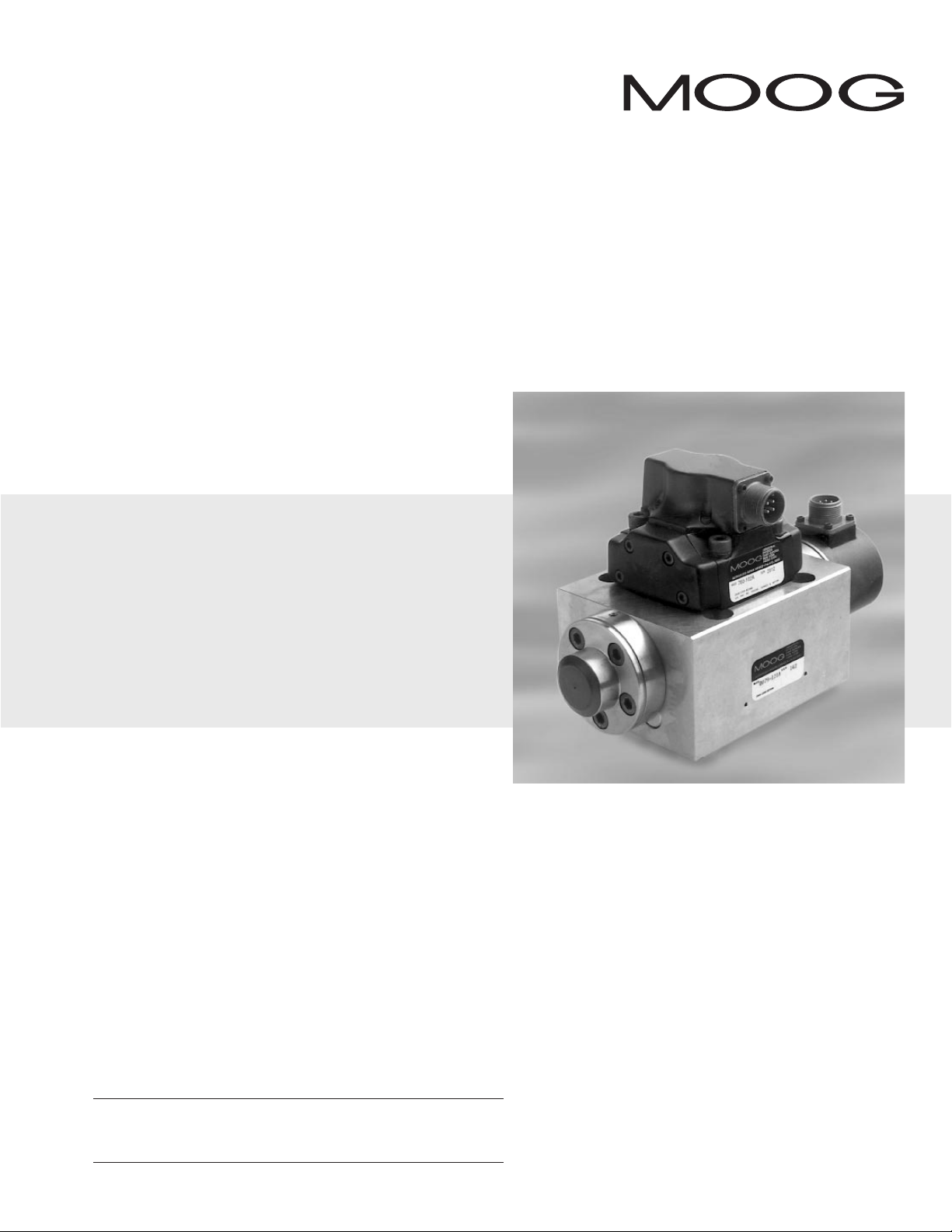
to install,operate and troubleshoot the Moog Inc.Series 79-100 Industrial
Servovalve.Loop closure of the third stage spool requires external electronics –
consult factory for suggested Moog electronics model numbers.
2.OPERATION
The Moog Inc. Series 79-100 Industrial Servovalve consists of a two stage
mechanical feedback pilot valve and a high flow third stage with electrical
feedback.Proper operation requires the use of user provided electronics to
condition the spool position transducer,compare actual spool position to
command and to generate a current signal to the pilot valve.
In a typical system,a spool position command signal is compared to the
actual spool position signal in the servoamplifier.The error (difference) is
converted to a current signal and used to drive the pilot valve spool in the
proper direction.The pilot valve spool directs oil flow to one end of the third
stage spool,moving the spool. Spool movement is sensed by the spool position
transducer and spool motion continues until the spool position signal is equal
to the command signal. At this point, the servoamplifier current returns to near
zero,the pilot valve returns to null and the third stage spool is held in position.
79-100 Series Installation and
Operation Instruction
Electrohydraulic Servovalve
CAUTION
DISASSEMBLY,MAINTENANCE,OR REPAIR OTHER THAN IN ACCORDANCE WITH THE
INSTRUCTIONS HEREIN OR OTHER SPECIFIC WRITTEN DIRECTIONS FROM MOOG WILL
INVALIDATE MOOG’S OBLIGATIONS UNDER ITS WARRANTY.
Page 2

3.HYDRAULIC SYSTEM PREPARATION
To prolong servovalve operational life and to reduce hydraulic system
maintenance, it is recommended that the hydraulic fluid be kept at a cleanliness
level of ISO DIS 4406 Code 16/13 maximum,14/11 recommended.The most
effective filtration scheme incorporates the use of a kidney loop or “off-line”
filtration as one of the major filtration components.The filter for the “off-line”
filtration scheme should be a ß3≥75 filter for maximum effectiveness.
Upon system startup and prior to mounting the servovalve, the entire
hydraulic system should be purged of built-in contaminating particles by an
adequate flushing.The servovalve should be replaced by a flushing manifold,and
the hydraulic circuit powered up under conditions of fluid temperature and fluid
velocity reasonably simulating normal operating conditions.New system filters
are installed during the flushing process whenever the pressure drop across the
filter element becomes excessive.The flushing processes should turn over the
fluid in the reservoir between fifty to one hundred times.
To maintain a clean hydraulic system,the filters must be replaced on a
periodic basis. It is best to monitor the pressure drop across the filter assembly
and replace the filter element when the pressure drop becomes excessive . In
addition to other filters that are installed in the hydraulic circuit,it is
recommended that a large capacity, low pressure ß3≥75 filter be installed in the
return line. This filter will increase the interval between filter element
replacements and greatly reduce the system contamination level.
4.INSTALLATION
The Moog 79-100 Series Industrial Servovalve may be mounted in any
position,provided the servovalve pressure,control and return ports match
respective manifold ports.
Caution: If the ser vovalve is mounted vertically,the third stage spool may drift
to one side when hydraulics are shut off.This may result in sudden movement of
equipment when starting up.
The mounting pattern and port location of the servovalve is shown on
Figure 2.The servovalve should be mounted with 3/8-16 x 2.5 inch long high
strength socket head capscrews. Apply a light film of oil to the screw threads
and torque to foot pounds.
On selected models,the pilot valve supply and return may be supplied
through external lines attached to the valve body or an intermediate manifold.
Wire mating connector for desired coil configuration and polarity. Thread
connector to valve.Wire transducer according to the installation drawing,
Figure 2.
5.MECHANICAL NULL ADJUSTMENT
There is no mechanical null adjust.Typically,a bias potentiometer is
provided on the electronics to null the valve. If adjustment of the transducer is
required,refer to the proper steps below.
a. Remove the two socket head screws holding the transducer cover to the
end cap.Carefully remove cover to prevent damage to the transducer
wiring.
b. Loosen the jam nut using a 15/8open end wrench.
c. Adjust transducer case to achieve required transducer null voltage.
Caution: Limit adjustment to ±2 turns. Excess loosening of transducer
case will result in the release of hydraulic fluid.
d. Tighten jam nut.Replace transducer cover,being careful not to damage the
transducer wires,using two socket head capscrews with lockwashers.
Torque to 10 inch pounds.
Tools and Equipment
a. Metric Allen wrench set
b. Standar d Allen wrench set
c. Open end wrench
6.GENERAL SERVICING RECOMMENDATIONS
a. Disconnect electrical lead to servovalve.
b. Relieve hydraulic system of residual pressure.
c. Remove servovalve.
Table 1.Replacement Parts
Part Description Qty. Part Number
Base O-Rings 4 42082-40
Pilot Valve Base O-Rings 4 42082-22
Base X-Y O-Rings 2 42082-12
Adapter Plate Base 3 42082-22
O-Rings 1 42082-8
Page 3

P otential Tr ouble
Servovalve does not follow input command
signal.(Actuator or components are
stationary or creeping slowly.)
High threshold.(Jerky, possible oscillatory
or “hunting” motion in closed loop system.)
Poor response.
Valve spool hardover.
Probable Cause
1.Plugged pilot valve filter.
2.Contaminated third stage.
1.Plugged pilot valve filter.
2.Contaminated third stage.
Partially plugged pilot valve filter.
1.Contaminated pilot valve.
2.System polarity reversed.
Remedy
1.Replace pilot valve filter.
2.Return to factory for service .
1.Replace pilot valve filter.
2.Return to factory for service .
Replace pilot valve filter.
1.Return to factory.
2.Verify system polarities.
7. TROUBLESHOOTING CHART
The following troubleshooting chart list potential troubles encountered,probable causes,and remedies.
8.FUNCTIONAL CHECKOUT AND CENTERING
a. Install servovalve on hydraulic system or test fixture,but do not connect
electrical lead.
b. Apply required system pressure to servovalve and visually examine for evi-
dence of external leakage. If leakage is present and cannot be rectified by
replacing O-Rings,remove the discrepant component and return for
repair or replacement.
c. Connect electrical leads to servovalve and check phasing in accordance
with system requirements.
9.AUTHORIZED REPAIR FACILITIES
If servovalve continues to malfunction after all recommended corrective
action procedures are performed,defective valve should be returned to Moog
for repair. Moog does not authorize any facilities other than Moog or Moog
subsidiaries to repair its servovalves.It is recommended you contact Moog at
(716)655-3000 to locate your closest Moog repair facility. Repair by an
independent (unauthorized) repair house will result in voiding the Moog
warranty and could lead to performance degradation or safety problems.
Page 4

79 SERIES INSTALLATION AND OPERATION INSTRUCTION
CDS6581 REV A 500-222 398
Moog Inc.,East Aurora,NY 14052-0018
Telephone: 716/655-3000
Fax:716/655-1803
Toll Free:1-800-272-MOOG
The products described herein are subject to change at any time without notice, including, but not limited to, product features, specifications, and designs.
Figure 2
TYPICAL WIRING SCHEMATIC
ACCESSORIES
Mating Electrical Connectors:
Pilot Valve:P/N 49054F14S2S
(MS3106F14S-2S
LVDT: P/N 49054F14S5S
(MS3106F14S-5S)
5.51
[140.0]
2.875
[73.03]
1.687
[42.85]
3.375
[85.73]
3.78 MAX
[96.0]
PILOT VALVE
EXTERNAL
NULL ADJUST
3/32 IN.
HEX SOCKET
2.95
[74.9]
1.61
[40.9]
1.72 MAX
[43.7]
2.17
[55.1]
3.83 MAX
[97.3]
4.33
[110.0]
TWO STAGE PILOT VALVE
760 SERIES SERVOVALVE
ELECTRICAL CONNECTOR
2.85 MAX
[72.4]
2.17
[55.1]
1.24
[31.5]
.26
[6.6]
.25
[6.4]
OPTIONAL ADAPTER PLATE
FOR EXTERNAL PILOT VALVE
PRESSURE AND RETURN.
PORTS ARE .750-16
SAE STR THD O-RING
FOR .50 O.D. TUBE FITTING
3.57
[90.7]
2.68
[68.1]
1.42
[36.1]
PIN C
PIN D
10.29
[261.4]
1.437
P
[36.50]
1.89
[48.0]
PIN A
PIN B
6.00
[152.4]
PIN A
.41 [10.5] THRU
M
.009
.67 [17.0]
TO DEPTH SHOWN
TRANSDUCER
ELECTRICAL
CONNECTOR
1.46
[37.1]
PIN B
PIN E
PIN C
PIN D
.83
[21.0]
3.79
[96.3]
LVDT
A
}
B
C
D
}
E
PRIMARY
SECONDARY
A
B
C
D
PILOT VALVE
R
P
OPTIONAL
PILOT SUPPLY
C
C
1
2
R
P
PILOT RETURN
1.
Ø .156
4X Ø .406 THRU
Ø .609 .50
1.000
2.125
4.250
2.000
.750
VALVE MOUNTS
ON THIS MANIFOLD
SURFACE
PORT PER SAE J1926
1.625-12 UNC-2B
DASH 20 STR THD ORING BOSS
(1.250 0.D. TUBE)
NEAR AND FAR-SIDE
Ø .31
2.875
4.250
2.125
.375-16 UNC-2B
1.
PILOT PRESSURE
Ø .156
.002
1.437
2.500
1.687
3.375
5.00
1.000
4X Ø .688
1.790
2.000
5.00
1.790
2.500
PORT PER SAE J1926
1.625-12 UNC-2B
DASH 20 STR THD ORING BOSS
(1.250 0.D. TUBE)
NEAR AND FAR-SIDE
4X 1.250
2.50
.005
NOTES:
1.
EXTERNAL PILOT SUPPLY AND RETURN PORTS SHOWN FOR REFERENCE ONLY.
MANIFOLD P/N 22236AM3 IS NOT PROVIDED WITH THESE PORTS.
PRESSURE
Industrial Controls Division
 Loading...