

Page 1
G77X/77X Series Installation
and Operation Instruction
1. INTRODUCTION
This manual provides instructions and procedures necessary
to install, operate and troubleshoot the Moog Inc.Series G771/G772/G773
(simplified as G77X) and 771/772/773 (simplified as 77X) Electrohydraulic
Industrial Servovalve.Troubleshooting instructions are outlined to permit the
identification of the specific component(s) suspected of failure.
2. OPERATION
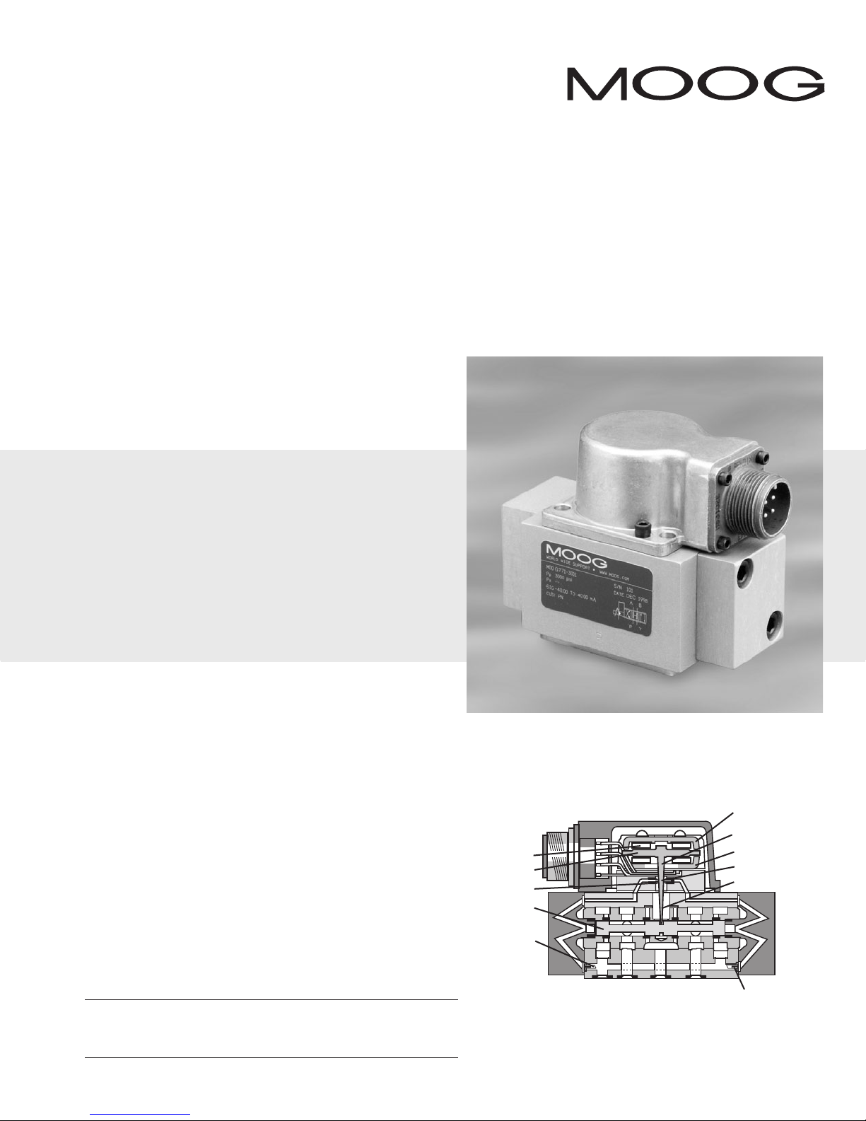
The Moog G77X/77X Series Industrial Servovalve consists of a polarized
electrical torque motor and two stages of hydraulic power amplification.The
motor armature extends into the air gaps of the magnetic flux circuit and is
supported in this position by a flexure tube member.The flexure tube acts as a
seal between the electromagnetic and hydraulic sections of the valve.The two
motor coils surround the armature, one on each side of the flexure tube.
Electrohydraulic Servovalve
The flapper of the first stage hydraulic amplifier is rigidly attached to the
midpoint of the armature.The flapper extends through the flexure tube and
passes between two nozzles, creating two variable orifices between the nozzle
tips and the flapper.The pressure controlled by the flapper and nozzle variable
orifice is fed to the end areas of the second stage spool.
The second stage is a conventional four-way spool design in which output
flow from the valve, at a fixed valve pressure drop, is proportional to spool
displacement from the null position. A cantilever feedback spring is fixed to the
flapper and engages a slot at the center of the spool. Displacement of the spool
deflects the feedback spring which creates a force on the armature/flapper
assembly.
Input signal induces a magnetic charge in the armature and causes a
deflection of the armature and flapper.This assembly pivots about the flexure
tube and increases the size of one nozzle orifice and decreases the size of the
other.
This action creates a differential pressure from one end of the spool to
the other and results in spool displacement.The spool displacement transmits a
force to the feedback wire which opposes the original input signal torque. Spool
movement continues until the feedback wire force equals the input signal force.
CAUTION
DISASSEMBLY, MAINTENANCE, OR REPAIR OTHER THAN IN ACCORDANCE WITH THE
INSTRUCTIONS HEREIN OR OTHER SPECIFIC WRITTEN DIRECTIONS FROM MOOG WILL
INVALIDATE MOOG’S OBLIGATIONS UNDER ITS WARRANTY.
ELECTROHYDRAULIC VALVE CUT-AWAY
Magnet
(not shown)
Coil
Armature
Nozzle
Spool
Filter
PB T A
Figure 1 Moog Series G77X/77X
Upper Polepiece
Flexure Sleeve
Lower Polepiece
Flapper
Feedback Wire
Inlet Orifice
Page 2
3. HYDRAULIC SYSTEM PREPARATION
To prolong servovalve operational life and to reduce hydraulic system
maintenance, it is recommended that the hydraulic fluid be kept at a cleanliness
level of ISO DIS 4406 Code 16/13 maximum, 14/11 recommended.The most
effective filtration scheme incorporates the use of a kidney loop or “off-line”
filtration as one of the major filtration components.The filter for the “off-line”
filtration scheme should be a ß3≥75 filter for maximum effectiveness.
Upon system startup and prior to mounting the servovalve, the entire
hydraulic system should be purged of built-in contaminating particles by an
adequate flushing.The servovalve should be replaced by a flushing manifold and
the hydraulic circuit powered up under conditions of fluid temperature and fluid
velocity, reasonably simulating normal operating conditions. New system filters
are installed during the flushing process whenever the pressure drop across the
filter element becomes excessive.The flushing processes should turn over the
fluid in the reservoir between fifty to one hundred times.
To maintain a clean hydraulic system, the filters must be replaced on a
periodic basis. It is best to monitor the pressure drop across the filter assembly
and replace the filter element when the pressure drop becomes excessive. In
addition to other filters that are installed in the hydraulic circuit, it is
recommended that a large capacity, low pressure ß3≥75 filter be installed in the
return line. This filter will increase the interval between filter element
replacements and greatly reduce the system contamination level.
4. INSTALLATION
The Moog G77X/77X Series Industrial Servovalve may be mounted in any
position, provided the servovalve pressure, piston and return ports match
respective manifold ports.
The mounting pattern, port location and mounting bolts of the servovalve
are shown on Figure 4. Apply a light film of oil to the screw threads and torque
to 57 inch-pounds.
Wire mating connector for desired coil configuration and polarity.
Thread connector to valve.
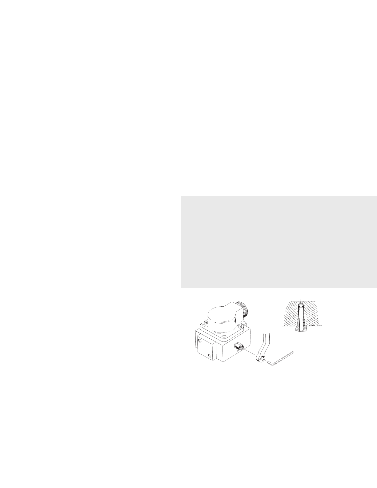
Adjustment Procedure
Using a 3/8inch offset box wrench, loosen the self-locking fitting until the
null adjustor pin can be rotated. (This should usually be less than 1/2 turn).
DO NOT remove self-locking fitting. Insert a 3/32inch Allen wrench in null
adjustor pin. Use the 3/32Allen wrench to rotate the mechanical null adjustor
pin to obtain desired flow null.Torque self-locking fitting to 57 inch lbs.
Note:
Clockwise rotation of null adjustor pin produces open loop flow from port B to port A.
Table 1. Replacement Parts
Part Description Qty. Part Number
G77X/77X Series Filter
Replacement Kit 1 B52555RK054K001
Inlet Orifice End Cap O-Rings (1) 2 42082-001
Inlet Orifice O-Rings (1) 2 42082-189
End Cap - Bushing O-Rings (1) 2 42082-042
Filter Tube (1) 1 C39486-005-060
End Cap - O-Rings (1) 2 42082-001
Base O-Rings
G771/771 4 42082-007
G772/772 4 42082-013
G773/773 4 42082-022
(1) Included in Filter Replacement Kit.
5. MECHANICAL NULL ADJUSTMENT
It is often desirable to adjust the flow null of a servovalve independent of
other system parameters.The “mechanical null adjustment” on the Moog
G77X/77X Series servovalve allows at least ±20% adjustment of flow null. The
“mechanical null adjustor” is an eccentric bushing retainer pin located above the
port designation on the valve body (see Figure 2) which, when rotated, provides
control of the bushing position. Mechanical feedback elements position the
spool relative to the valve body for a given input signal.Therefore, a movement
of the bushing relative to the body changes the flow null.
Figure 2
Mechanical Null Adjustment
6. GENERAL SERVICING RECOMMENDATIONS
a. Disconnect electrical lead to servovalve.
b. Relieve hydraulic system of residual pressure.
c. Remove servovalve.
Page 3

7.TROUBLESHOOTING CHART
The following troubleshooting chart list potential troubles encountered,probable causes, and remedies.
Potential Trouble
Servovalve does not follow input command
signal. (Actuator or components are
stationary or creeping slowly.)
High threshold. (Jerky,possible oscillatory
or “hunting” motion in closed loop system.)
Poor response. (Servovalve output lags
electrical command signal).
High Null Bias. (High input current required
to maintain hydraulic cylinder or motor
stationary.)
Figure 3
Inlet Orifice O-Rings (two at each end cap)
Probable Cause
Plugged inlet filter element.
Plugged filter element.
Partially plugged filter element.
1. Incorrect null adjustment
2. Partially plugged filter element.
Filter
End cap
End Cap O-Rings
Remedy
Replace filter element.
Replace filter element.
Replace filter element and check for dirty
hydraulic fluid in system.
1. Readjust null
2. Replace filter element and check for dirty
hydraulic fluid in system.
Tools and Equipment
a. Blade screwdriver
16
b.3/
Allen wrench
c. No. 2-56 NC by 11/2inch screw
d. Torque wrenches
8. FILTER ASSEMBLY REPLACEMENT
a. Remove four socket head cap screws and lockwashers using a 3/16inch
Allen wrench. Remove end caps. (See Figure 3).
b. Remove O-Rings from end caps.
c. Remove inlet orifice assembly from both sides of body.
Note: 2-56 screw threads into the filter plug and inlet orifice assembly.
Remove filter.The inlet orifice assemblies are matched to each other and
are therefore interchangeable.
Note: These assemblies seat in body and cannot go through bore
during removal.
d. Remove O-Rings from inlet orifice assemblies.
e. Visually inspect orifice assemblies for damage or foreign material.
f. Discard O-Rings and filters.
g. Install O-Rings on inlet orifices.
h. Install filter and inlet orifice assembly in body.Inlet orifice assembly pilots
into filter. Install the other inlet orifice assembly into other end of filter.
Inlet orifice assemblies are interchangeable.
i. Install O-Rings on end caps.
j. Install end caps on body and install four socket head cap screws and
lockwashers.Torque the screws to 85 inch-pounds.
9. FUNCTIONAL CHECKOUT AND CENTERING
a. Install servovalve on hydraulic system or test fixture,but do not connect
electrical lead.
b. Apply required system pressure to servovalve and visually examine for evi-
dence of external leakage. If leakage is present and cannot be rectified by
replacing O-Rings, remove the discrepant component and return for
repair or replacement.
Note: If the system components are drifting or hardover, adjust
the mechanical null of the servovalve.
c. Connect electrical lead to servovalve and check phasing in accordance
with system requirements.
10.AUTHORIZED REPAIR FACILITIES
If servovalve continues to malfunction after all recommended corrective
action procedures are performed,defective valve should be returned to Moog
for repair. Moog does not authorize any facilities other than Moog or Moog
subsidiaries to repair its servovalves. It is recommended you contact Moog at
(716) 652-2000 to locate your closest Moog repair facility.Repair by an
independent (unauthorized) repair house will result in voiding the Moog
warranty and could lead to performance degradation or safety problems.
Page 4

P A B T G F1 F2 F3 F4
4.85 4.85 4.85 4.85 2.39 M5 M5 M5 M5
X 21.3 13.5 29.5 21.3 11.4 0 42.9 42.9 0
Y 9.1 17.0 17.0 24.9 4.3 0 0 34.0 34.0
P A B T G F1 F2 F3 F4
6.6 6.6 6.6 6.6 2.39 M5 M5 M5 M5
X 21.3 11.4 31.2 21.3 11.4 0 42.9 42.9 0
Y 7.2 17.0 17.0 27.0 4.3 0 0 34.0 34.0
P A B T G F1 F2 F3 F4
7.92 7.92 7.92 7.92 2.39 M6 M6 M6 M6
X 21.3 9.7 33.3 21.3 11.4 0 42.9 42.9 0
Y 5.1 17.0 17.0 29.0 4.3 0 0 34.0 34.0
G77X/77X SERIES INSTALLATION AND OPERATION INSTRUCTION
47.8
1.57
44.5
MAX
47.8
1.343
35.3
64.77
26.2
P
3.0
OR
[28.4]
1.75
1.275
.844
1.06
MAX
PIN C
1.00
2.12
2.18
2.81
17.04
.014
1.688
34.11
1.56
1.88
PIN D
1.88
.12
.007
(OPTION)
21.44
25.4
26.9
1.39
39.6
1.12 MAX
1.03
MTG HGT
PIN B
.671
53.8
55.4
71.4
PIN A
32.39
2.550
42.88
ELECTRICAL CONNECTOR
LOCATING PIN
Ø.062
EXTERNAL NULL ADJUST
3/32 IN. HEX SOCKET
4X Ø.221(5.61) THRU (G771 AND G772)
4X Ø.265(6.73) THRU (G773)
P A B T G F1 F2 F3 F4
Ø .191 Ø .191 Ø .191 Ø .191 Ø .094 .190-32 .190-32 .190-32 .190-32
X 0.84 0.53 1.16 0.84 0.45 0 1.69 1.69 0
Y 0.36 0.67 0.67 0.98 0.17 0 0 1.34 1.34
P A B T G F1 F2 F3 F4
Ø .260 Ø .260 Ø .260 Ø .260 Ø .094 .190-32 .190-32 .190-32 .190-32
X 0.84 0.45 1.23 0.84 0.45 0 1.69 1.69 0
Y 0.28 0.67 0.67 1.06 0.17 0 0 1.34 1.34
P A B T G F1 F2 F3 F4
Ø .312 Ø .312 Ø .312 Ø .312 Ø .094 .250-20 .250-20 .250-20 .250-20
X 0.84 0.38 1.31 0.84 0.45 0 1.69 1.69 0
Y 0.20 0.67 0.67 1.14 0.17 0 0 1.34 1.34
Y
X
T
BA
P
F2
F3
F4
F1
T
G
6
NOTES
1 Fluid:
Industrial type petroleum base hydraulic
fluid, maintained to ISO DIS 4406 Code
14/11 recommended.
2 Operating Temperature Range:
-20°F [-29°C] to +275°F [+135°C]
3 Valve Phasing:
Flow out port B results when Series
coils: B & C connected,A+, D-;
Parallel coils:A & C connected, B & D
connected; Single coil:A+, B-, or C+, D-.
4 Ports:
See table below left.
5 Surface:
Surface to which valve is mounted
requires 32[ ] finish, flat within 0.002
[0.05] TIR.
6 Null Adjust:
Flow out port B results with clockwise
rotation of null adjust screw (3/32 hex key).
Flow bias is continually varied for a given
port as the null adjust is rotated.
∆∆
G771/771 U.S. METRIC
G772/772 U.S. METRIC
G773/773 U.S. METRIC
Figure 4
4 Three standard designs are available.
Model Diameter Diameter Manifold O-Rings Mounting Bolt Size
Number in mm in mm Moog MS (socket head cap screws)
G771/771 .625 15.8 .191 4.85 -007 -010 .190-32 NF x 2.0 long
G772/772 .780 19.8 .260 6.60 -013 -012 .190-32 NF x 2.0 long
G773/773 .937 23.8 .312 7.93 -022 -013 .250-20 NF x 2.25 long
The products described herein are subject to change at any time without notice, including, but not limited to, product features, specifications, and designs.
Port Circle Port
TYPICAL WIRING SCHEMATIC
ABCD
3
Moog Inc., East Aurora, NY 14052-0018
Telephone:+1-716-652-2000
Fax: +1-716-687-7910
Toll Free:+1-800 -272-MOOG
www.moog.com/industrial
©2007 Moog Inc. All changes are reserved.
CDS6674 REV C 500-380 807
 Loading...