

Page 1
PAN & TILT
POSITIONERS_
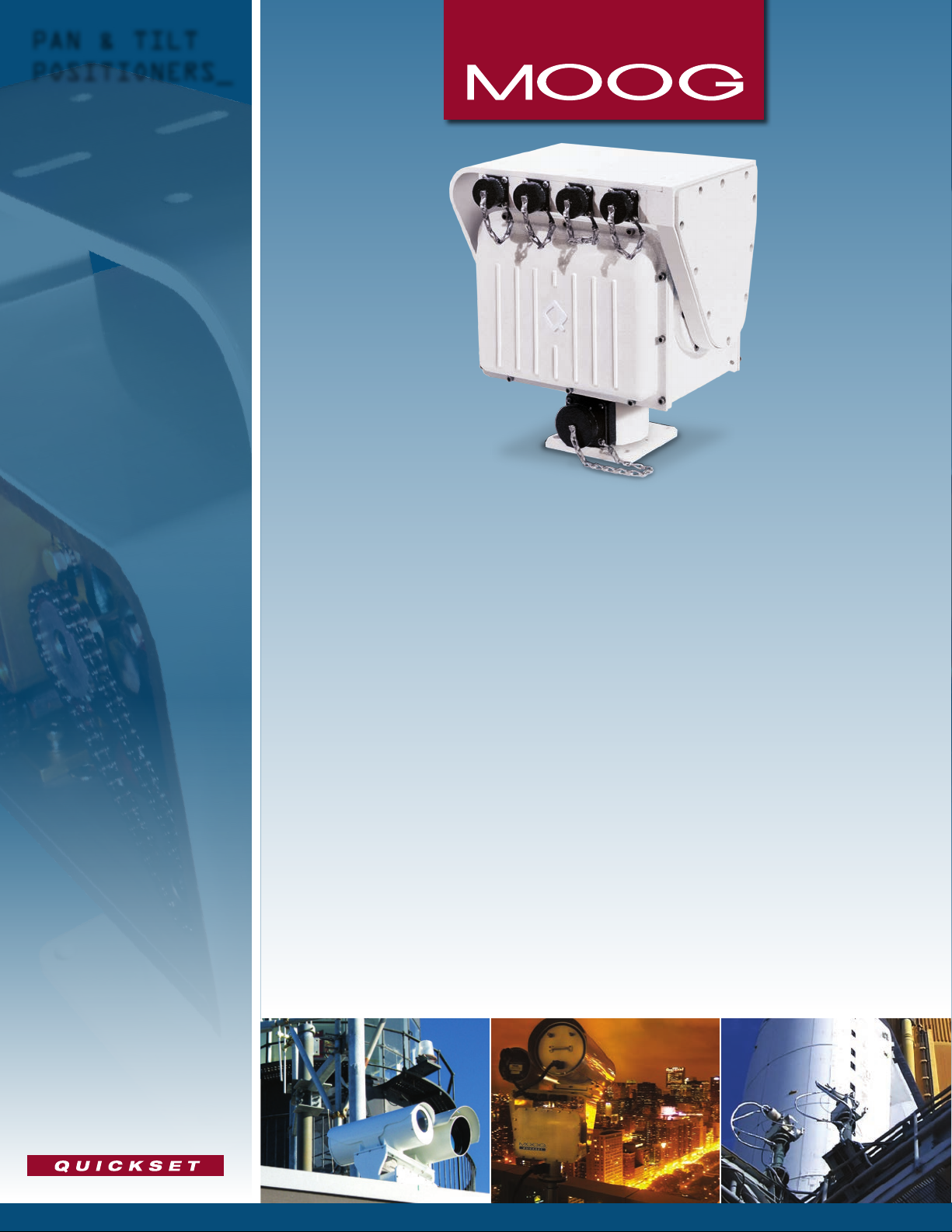
QPT-50 Series
Pan & Tilt Positioners
The QPT-50 Series of Pan & Tilt positioners are designed for a wide variety of applications. They are rugged and durable for
virtually any harsh environment. The QPT-50 can handle payloads up to 50 lb-ft of torque making it suitable for a wide
range of sensors.
Multiple models are available to t your needs. Integrated Control (IC) units communicate via networked PC or through
a separate controller. IC units feature integrated dual sensor serial control, lens drive and power supply interface
making sensor integration quick and easy. Analog units provide effective solutions where simple command and control
are required without a PC. The Sentry line utilizes Stepper Motor technology for more precise accuracy and broader
speed control.
Available Features
• Payloads up to 50 lb-ft
• Analog driven or Digital Serial Integrated Controller
(IC) models
• Mounting platforms include plain formed table top,
table top with single tilt-axis connector, and 4 connector
Universal models
• Internal wire table top for pass-through or IC sensor
wiring on certain models
• Fixed, Inverted or Mobile Installations
• Mil-Spec Connectors
• Tough metal housing and gearing for durability in
harsh environments
(67.8 Nm)
• Marine conguration that meets IP-67 standards
• RF pass-through connectivity (RF rotary joint,
1 and 2 channels)
• Pressurized housing available
Sensor Integration
• Multi-Spectrum Cameras (Visible / NIR / SWIR)
• Thermal Imagers (LWIR)
• IR and Visible Illuminators
• Laser Range Finders
• Communication Antennas
• Acoustic Devices
Page 2

QPT-50 Series
QPT-50 Series
Serial IP Features
Available with DC brush or stepper motors
Microprocessor control
Software controlled with status feedback
Serial Communication: RS232 / 422 / 485 and IP
Control Protocols: Moog QuickSet and Pelco D
programmable tours
2
and 32 presets
Motor drivers for camera lens zoom and focus control
2 Auxiliary relay controls for wipers, illuminators, laser range nders, etc.
Simple command and control with one controller for one positioner
Universal Features
Pass-through wiring
Full feature serial control of sensors
Analog Features
Azimuth / Elevation position feedback output
Power supply integrated into controller
Standard Performance
Load Capacity:
Operating Voltage Range:
Total Power:
Pan-Axis Range:
Pan-Axis Speed:
Tilt-Axis Range:
Tilt-Axis Speed:
Internal Heater:
Operating Temperature:
Rotational Limits:
Feedback:
Repeatability:
Duty Cycle:
Motor Type / Drive:
Communication to Pan & Tilt:
Communication to Sensors:
Control Protocol:
Connector Specications:
Load Connector Interfaces:
Materials:
Finish / Color:
Weight:
Dimensions:
Test Cable and Software:
Note: Test software compatible with Windows-95 SP2, 98, ME, 2000 and XP version. Not compatible with NT. Moog control protocol documentation supplied. Different models may vary.
50 lb-ft (67.8 Nm) maximum
24VDC (±4VDC)
Pan & Tilt Axes: 6.5A pk, 2.5A continuous at 24VDC • Heater: 2.7A at 24VDC • Standby: <0.7A at 24VDC (no heater current)
360° continuous rotation (slip ring) • 435° (±217.5°) (non-slip ring)
0.005° – 50°/sec
180° (±90°)
0.005° – 12°/sec at 50 lb-ft
Thermostatically controlled 0°C (32°F) ON • 1.7°C (35°F) OFF
Without Heater: -15°C to 55°C (5°F to 131°F) • With Heater: -30°C to 55°C -22°F to 131°F
Fixed tilt hard limit, adjustable soft limits on both axes
Optical Encoders (0.01° readout)
0.25° (Pan - 0.05°, Tilt - 0.05° on Sentry models)
20%
Stepper (Sentry) and DC Brush
RS232 / 422 / 485, IP Ethernet: 10/100 Base-T
RS232 / 422, Ethernet Pass-Through
Moog QuickSet or Pelco D
Mil-Spec grade used on all congurations
1 Mil-Spec connector at tilt axis (certain models) • 4 Mil-Spec connectors on Universal tilt table top
Housing 6061-T6 Aluminum, stainless steel hardware, permanently sealed radial ball bearings
White powder coat paint over alodined chromate for corrosion resistance standard. Other colors and CARC available upon request
26 lbs (11.8 kg) to 36 lbs (16.3 kg) depending on model
See page 4
6 ft test cable and software included with all IC and Sentry congurations
2
Page 3

Sentry Universal
4-Port Payload Connectivity*
Formed Table (FT)
Formed Table (FT)
Tilt A/B Payload Connectivity**
Serial/IP Conguration
DC Brush-Type Motor Conguration Stepper Motor Congurations (Sentry)
24 VDC 24 VAC 24 VDC
Pan Speed Range (deg / sec):
Tilt Speed Range (deg / sec):
Weight:
26 lbs (11.8 kg) to 36 lbs (16.3 kg) 26 lbs (11.8 kg) to 36 lbs (16.3 kg) 26 lbs (11.8 kg) to 36 lbs (16.3 kg)
1° – 25° 1° – 25° 0.005° – 50°
0.3° – 7° 0.3° – 7° 0.005° – 12°
Analog Conguration
12 VDC 24 VDC
Pan Speed Range (deg / sec):
Tilt Speed Range (deg / sec):
Weight:
Note: Speed ranges dependent on model, weight and payload conguration - contact factory for details
* 4-Port Payload Connectivity
* 2-Channel: Internal processor payload serial control, camera lens drivers / feedback input, Ethernet, payload power supply, video coax to base connector wiring.
* 2-Channel: Payload pass-through wiring for customer supplied payload interfacing including Ethernet, power, serial control, video coax to base connector wiring, and more.
(See details in Moog Universal Pan / Tilt data sheet)
** Tilt A, Single Channel Payload Connectivity:
Internal processor payload serial control, camera lens drivers / feedback input, Ethernet, payload power supply.
** Tilt B, Single Channel Payload Connectivity:
Payload pass-through wiring for customer supplied payload interfacing. Includes base to tilt connector wiring for Ethernet, power, serial control, video coax to base connector wiring, and more.
1° – 8° 0.5 – 9°
1° – 3° 0.1 – 3°
26 lbs (11.8 kg) 26 lbs (11.8 kg)
3
Page 4

0.4
[ 10.08 ]
3.36
[ 85.28 ]
4.25
[ 107.95 ]
3.36
[ 85.34 ]
4.25
[ 107.95 ]
3.94
[ 100.01 ]
1.13
[ 28.58 ]
1.69
[ 42.93 ]
5.0
[ 127 ]
3.5
[ 88.9 ]
2.75
[ 69.85 ]
7.88
[ 200.03 ]
4.5
[ 114.3 ]
9.63
[ 244.6 ]
7.25
[ 184.15 ]
3.19
[ 80.98 ]
5.62
[ 142.62 ]
10.44
[ 265.05 ]
2.88
[ 73.15 ]
10.26
[ 260.5 ]
0.25
[ 6.35 ]
2.05
[ 52 ]
4.0
[ 101.6 ]
0.12
[ 3.05 ]
0.28
[ 7.14 ]
5.83
[ 148 ]
0.31
[ 7.87 ]
0.27
[ 6.8 ]
1.18
[ 30 ]
3.76
[ 95.5 ]
4.0
[ 101.6 ]
5.0
[ 127 ]
3.9
[ 99.06 ]
3.84
[ 97.54 ]
0.22
[ 5.56 ]
4.25
QPT-50 Series
QPT-50 Series
Dimensions / Architectural Drawings
Standard Housing
5.50
139.70
12.69
322.31
Dimensions / Architectural Drawings
Sentry Universal
4.81
7.81
6.74
2.88
1.81
46.04
73.22
0
Ø .27
6.73
9.65
245.12
3.04
77.19
5.90
149.86
198.44
171.26
122.24
11.72
297.69
Ø 3.25
231.75
10.70
271.72
82.55
9.12
0
0
0
.50
12.70
1.41
35.79
2.00
50.80
2.59
65.81
3.50
88.90
2
107.95
3.36
85.34
4.25
3.36
107.95
85.28
6.24
158.57
5.50
139.70
7.25
184.16
158.75
209.55
Dimensions are in Inches [mm]
Ø .40
10.08
6.25
8.25
©2013 Moog, Inc. All rights reserved.
Product and company names listed are trademarks
or trade names of their respective companies.
Specifications are subject to change, to confirm current
call +1 847.498.0700.
Sentry 50 Torque Curve
55
50
45
40
35
30
Dimensions are in Inches [mm]
Sensor and Surveillance Systems
3650 Woodhead Drive Northbrook, IL. USA 60062-1895
+1.847.498.0700 Fax: +1.847.498.1258
www.moogS3.com
This product is regulated by the U.S. Export Administration Regulations 15 CFR Parts 730-774, ECCN EAR99,
export, disclosure or transfer contrary to U.S. law is prohibited.
25
SPEED (deg / sec)
20
15
10
5
0
5 10 15 20 25 30 35 40 45 50
TOP LOAD FORCE (FT – LBS) *Upright Mounting
Load (ft. -lbs.) vs Speed (deg / sec) @ 24VDC
Pan
Tilt
Form 500-630 102113
 Loading...