

Page 1

1. INTRODUCTION
This manual provides instructions and procedures necessary to install,
operate and troubleshoot the Moog G761/761 series industrial servovalve.
Troubleshooting instructions are outlined so that only the specific component(s)
suspected of failure may be identified.
2. OPERATION
The Moog G761/761 series industrial servovalve consists of a polarized
electrical torque motor and two stages of hydraulic power amplification. The
motor armature extends into the air gaps of the magnetic flux circuit and is
supported in this position by a flexure tube member. The flexure tube acts as a
seal between the electromagnetic and hydraulic sections of the valve. The two
motor coils surround the armature, one on each side of the flexure tube.
G761/761 Series Installation and
Operation Instruction
Electrohydraulic Servovalve
The flapper of the first stage hydraulic amplifier is rigidly attached to the
midpoint of the armature. The flapper extends through the flexure tube and
passes between two nozzles, creating two variable orifices between the nozzle
tips and the flapper. The pressure controlled by the flapper and nozzle variable
orifice is fed to the end areas of the second stage spool.
The second stage is a conventional 4-way spool design in which output
flow from the valve, at a fixed valve pressure drop, is proportional to spool
displacement from the null position. A cantilever feedback spring is fixed to
the flapper and engages a slot at the center of the spool. Displacement of the
spool deflects the feedback spring which creates a force on the armature/flapper
assembly.
Input signal induces a magnetic charge in the armature and causes a
deflection of the armature and flapper. This assembly pivots about the flexure
tube and increases the size of one nozzle orifice and decreases the size of the
other.
This action creates a differential pressure from one end of the spool to
the other and results in spool displacement. The spool displacement transmits a
force in the feedback wire which opposes the original input signal torque. Spool
movement continues until the feedback wire force equals the input signal force.
CAUTION
DISASSEMBLY, MAINTENANCE, OR REPAIR OTHER THAN IN ACCORDANCE WITH THE
INSTRUCTIONS HEREIN OR OTHER SPECIFIC WRITTEN DIRECTIONS FROM MOOG, WILL
INVALIDATE MOOG’S OBLIGATIONS UNDER ITS WARRANTY.
ELECTROHYDRAULIC VALVE CUT-AWAY
Coil
Armature
Nozzle
Feedback Wire
Spool
Filter
P A T B P
Figure 1 Moog Series G761/761
Upper Polepiece
Flexure Tube
Lower Polepiece
Flapper
Inlet Orifice
x
Page 2
Relocate screw
and seal washer to
P port for external
(5th port) pilot
oil supply
Location of
screw and seal
washer for
standard internal
(4th port) pilot
oil supply
3. HYDRAULIC SYSTEM PREPARATION
To prolong servovalve operational life and to reduce hydraulic system
maintenance, it is recommended that the hydraulic fluid be kept at a cleanliness
level of ISO DIS 4406 Code 16/13 maximum, 14/11 recommended. The most
effective filtration scheme incorporates the use of a kidney loop or “off-line”
filtration as one of the major filtration components. The filter for the “off-line”
filtration scheme should be a B3≥75 filter for maximum effectiveness.
Upon system startup and prior to mounting the servovalve, the entire
hydraulic system should be purged of built-in contaminating particles by an
adequate flushing. The servovalve should be replaced by a flushing manifold and
the hydraulic circuit powered up under conditions of fluid temperature and fluid
velocity, reasonably simulating normal operating conditions. New system filters are
installed during the flushing process whenever the pressure drop across the filter
element becomes excessive. The flushing processes should turn over the fluid in
the reservoir between fifty to one hundred times.
To maintain a clean hydraulic system, the filters must be replaced on
a periodic basis. It is best to monitor the pressure drop across the filter
assembly and replace the filter element when the pressure drop becomes
excessive. In addition to other filters that are installed in the hydraulic circuit,
it is recommended that a large capacity, low pressure ß3≥75 filter be installed
in the return line. This filter will increase the interval between filter element
replacement and greatly reduce the system contamination level.
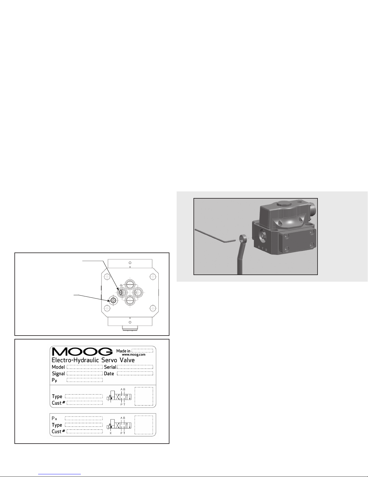
4. PILOT STAGE OIL SUPPLY AND NAMEPLATE
MODIFICATION (applies to models G761-3001B through G761-3010B)
The Moog G761/761 series industrial servovalve can be configured for pilot
stage oil supply through the internal pressure “P” port, or from a separate supply
line through the “X” port. Standard configuration is internal pilot operation with
a screw and seal washer in the “X” port. This same screw and seal washer must
be relocated to the “P” port if an external pilot oil supply source is desired. Refer
to Figure 2 for screw and seal washer locations.
Upon valve installation, the nameplate must display the proper hydraulic
schematic and typecode (if applicable). The nameplate currently shows internal
(4th port) pilot hydraulic schematics and typecode. If a separate pilot supply will
be used, please attach the provided lower half label showing external (5th port)
information. See Figure 3.
5. INSTALLATION
The Moog G761/761 series industrial servovalve may be mounted in any
position, provided the servovalve pressure, control and return ports match their
respective manifold ports.
The mounting pattern and port locations of the servovalve are shown on
Figure 6. The servovalve should be mounted with 5/16-18 x 1.75 inch long, socket
head cap screws. Apply a light film of oil to the screw threads and torque to
96 inch pounds. Wire the mating connector for desired coil configuration and
polarity. Thread the connector to valve.
6. NULL ADJUSTMENT
It is often desirable to adjust the flow null of a servovalve independent
of other system parameters. The “mechanical null adjustment” on the Moog
G761/761 series servovalve allows at least ±20% adjustment of flow null.
The “mechanical null adjustor” is an eccentric bushing retainer pin located
above the “return” port designation on the valve body (see Figure 4) which, when
rotated, provides control of the bushing position. Mechanical feedback elements
position the spool relative to the valve body for a given input signal. Therefore, a
movement of the bushing relative to the body, changes the flow null.
Figure 4
Mechanical Null Adjustment
Figure 2
Figure 3
Sample
Nameplate
Mechanical Adjustment Procedure
Using a 3/8 inch offset box wrench, loosen the self-locking fitting until the
null adjustor pin can be rotated. (This should usually be less than 1/2 turn).
DO NOT remove self-locking fitting. Insert a 3/32 inch Allen wrench in null
adjustor pin. Use the 3/32 Allen wrench to rotate the mechanical null adjustor
pin to obtain desired flow null. Torque self-locking fitting to 57 inch lbs.
7. GENERAL SERVICING RECOMMENDATIONS
a. Disconnect the electrical lead to the servovalve.
b. Relieve the hydraulic system of residual pressure.
c. Remove the servovalve.
Important:
Local regulations may require precise hydraulic labeling on components!
Page 3
8. TROUBLESHOOTING CHART
The following troubleshooting chart lists potential troubles encountered, probable causes and remedies.
Potential Trouble
Servovalve does not follow input command
signal. (Actuator or components are
stationary or creeping slowly).
High threshold. (Jerky, possible oscillatory
or “hunting” motion in closed loop system).
Poor response. (Servovalve output lags
electrical command signal).
High Null Bias, (High input current
required to maintain hydraulic cylinder or
motor stationary).
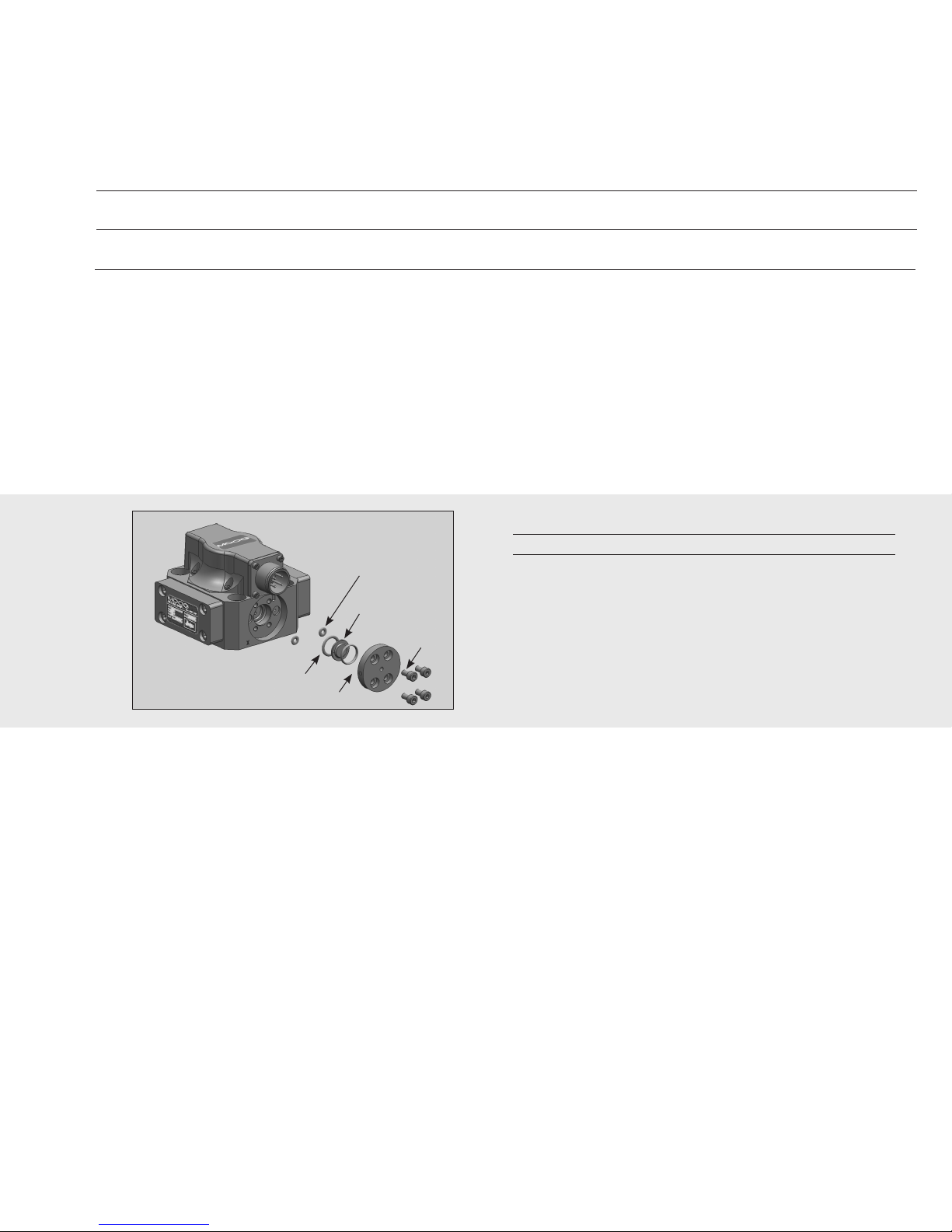
Figure 5
2X O-Ring P/N G2141-013-015
Filter Retainer
Probable Cause
1. Plugged filter element.
1. Plugged filter element.
1. Partially plugged filter element.
1. Incorrect null adjustment.
2. Partially plugged filter element.
2X O-Ring
P/N -42082-003
Filter
P/N A67999-065
Socket Head
Cap Screw
Remedy
1. Replace filter element.
1. Replace filter element.
1. Replace filter element.
Check for dirty hydraulic fluid in system.
1. Readjust null.
2. Replace filter element and check for
dirty hydraulic fluid in system.
Table 1. Replacement Parts
Part Description Qty. Part Number
G761/761 Series Filter Replacement Kit 1 B52555RK201K001
O-Ring (1) 2 -42082-003
O-Ring (1) 2 G2141-013-015
Filter Disc (1) 1 A67999-065
Base O-Rings 4 -42082-022
1 -42082-013
(1) Included in Filter Replacement Kit
9. FILTER ASSEMBLY REPLACEMENT
Tools and Equipment
a. 3mm Allen wrench
b. Torque wrench
a. Remove the four socket head cap screws with 3mm Allen wrench.
b. Remove the filter retainer.
c. Remove and discard the filter disc.
d. Remove and replace the o-ring on the filter retainer and the o-ring in
the filter bore.
e. Reinstall in reverse order, torque screws to 35-40 in-lbs.
10. FUNCTIONAL CHECKOUT AND CENTERING
a. Install servovalve on hydraulic system or test fixture, but do not connect
electrical lead.
b. Apply required system pressure to servovalve and visually examine for evi dence of external leakage. If leakage is present and cannot be rectified by
replacing o-rings, remove the discrepant component and return for
repair or replacement.
Note: If the system components are drifting or hardover, adjust
the mechanical null of the servovalve.
c. Connect electrical lead to servovalve and check phasing in accordance
with system requirements.
11. AUTHORIZED REPAIR FACILITIES
Moog does not authorize any facilities other than Moog or Moog
subsidiaries to repair its servovalves. It is recommended you contact Moog
at (716) 652-2000 to locate your nearest Moog repair facility. Repair by an
independent (unauthorized) repair house will result in voiding the Moog
warranty and could lead to performance degradation or safety problems.
Page 4
G761/761 SERIES INSTALLATION AND OPERATION INSTRUCTION NOTES
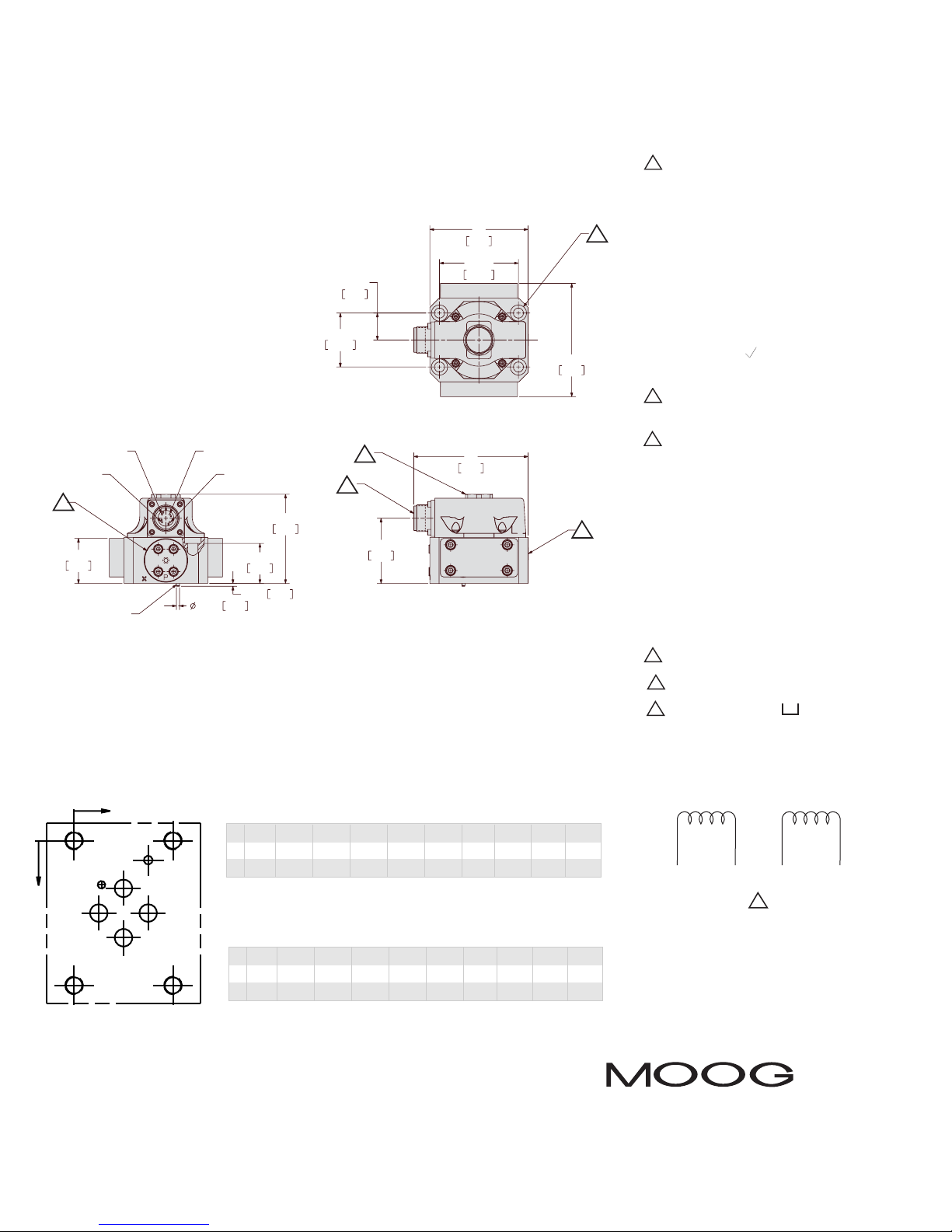
PA BTXGF1 F2 F3 F4
1 Valve Weight:
Aluminum Body: 2.4 lbs (1.08 kg)
Steel Body: 4.0 lbs (1.81 kg)
2 Polarity:
A&C (+), B&D (-) produces flow out
port B
3 Manifold O-Rings:
0.070 (1.78) sect x 0.426 (10.82) I.D.
(Universal dash No. 13) for P, A, B, T port
0.070 (1.78) sect x 0.364 (9.25) I.D.
(Universal dash No. 12) for X port
4 Surface:
Surface to which valve is
mounted requires 32 ( 0.8 ) finish, flat
within .001 (0.025) TIR
5 Electrical Connector:
Mates with MS3106F14S-2S or equivalent
6 Null Adjust:
Flow out of port B will increase with
clockwise rotations of null adjust (3/32
hex key). Flow bias is continually varied
for a given port as the null adjust is
rotated.
7 Compressed Oil Volume for one
control port: 0.229 in3 (3.75 cm3)
8 Suggested Mounting Screws:
0.312-18 x 1.75 lg (M8 x 45)
socket head cap screw (4 req’d)
9 Optional Magnetic Null Adjust
10 Replaceable Filter Access Cover
11 4X Ø .329 (8.36) thru Ø .531 to
depth shown mounting holes.
PIN C
10
37
1.46
LOCATING PIN
PIN D
PIN A
PIN B
2.57 .101
2.90
33.0
1.30
2.34 .092
81
3.19
65.07
22.22
.875
44.45
1.750
9
5
74
53.7
2.12
2.562
94
3.71
93
3.68
11
6
X
F1
P
G
F2
X
P
x
U.S.
5
Ø.32 Ø.32 Ø.32 Ø.32 Ø.2 Ø.14
/
-18
16
X 0.87 0.44 1.31 0.87 1.31 0.48 0 1.75 1.75 0
Y 0.84 1.28 1.28 1.72 0.34 0.78 002.56 2.56
Y
A
T
F4
B
Figure 6
The products described herein are subject to change at any time without notice, including, but not limited to, product features, specifications, and designs.
METRIC
PA BTXGF1 F2 F3 F4
Ø8.2 Ø8.2 Ø8.2 Ø8.2 Ø5.0 Ø3.5 M8 M8 M8 M8
F3
X 22.2 11.1 33.3 22.2 33.3 12.3 0 44.4 44.4 0
Y 21.4 32.5 32.5 43.6 8.7 19.8 0065.0 65.0
Dimensions in parenthesis are in millimeters.
5
5
/
-18
16
5
/
/
-18
-18
16
16
A B C D
2
Moog Inc., Industrial Group
www.moog.com/industrial
United States: phone +1 716 652-2000 info.us@moog.com
Europe: phone +49 7031 622 0 info.germany@moog.com
Asia Pacific: phone +81 45 680 2500 info.japan@moog.com
For a complete list www.moog.com/industrial/globallocator
CDS6673 Rev E 1216
 Loading...