

Page 1
72 Series Installation and
Operation Instruction
1. INTRODUCTION
This manual provides instructions and procedures necessary
to install, operate and troubleshoot the Moog Series 72 Electrohydraulic
Industrial Servovalve.Troubleshooting instructions are outlined to permit the
identification of the specific component(s) suspected of failure.
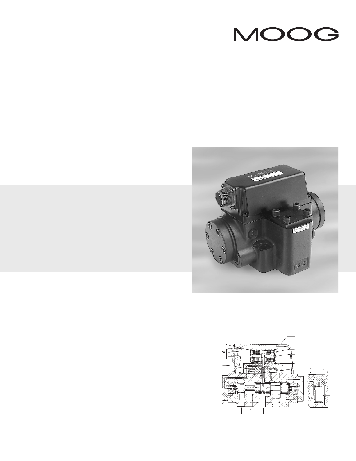
2. OPERATION
The Moog Series 72 Electrohydraulic Servovalve consists of a polarized
electrical torque motor and two stages of hydraulic power amplification (see
Figure 1).The motor armature extends into the air gaps of the magnetic flux
circuit and is supported in this position by a flexure tube member.The flexure
tube acts as a seal between the electromagnetic and hydraulic sections of the
valve.The two motor coils surround the armature, one on each side of the
flexure tube.
Electrohydraulic Servovalve
The flapper of the first stage hydraulic amplifier is rigidly attached to the
midpoint of the armature.The flapper extends through the flexure tube and
passes between two nozzles, creating two variable orifices between the nozzle
tips and the flapper.The pressure controlled by the flapper and nozzle variable
orifice is fed to the end areas of the second stage spool.
The second stage is a conventional four-way spool design in which output
flow from the valve, at a fixed valve pressure drop, is proportional to spool
displacement from the null position.A cantilever feedback spring is fixed to the
flapper and engages a slot at the center of the spool. Displacement of the spool
deflects the feedback spring which creates a force on the armature/flapper
assembly.
Input signal induces a magnetic charge in the armature and causes a
deflection of the armature and flapper.This assembly pivots about the flexure
tube and increases the size of one nozzle orifice and decreases the size of the
other.
This action creates a differential pressure from one end of the spool to
the other and results in spool displacement.The spool displacement causes a
force in the feedback wire which opposes the original input signal torque. Spool
movement continues until the feedback wire force equals the input signal force.
CAUTION
DISASSEMBLY, MAINTENANCE, OR REPAIR OTHER THAN IN ACCORDANCE WITH THE
INSTRUCTIONS HEREIN OR OTHER SPECIFIC WRITTEN DIRECTIONS FROM MOOG WILL
INVALIDATE MOOG’S OBLIGATIONS UNDER ITS WARRANTY.
ELECTROHYDRAULIC VALVE CUT-AWAY
Polepiece
Connector
Filter
Feedback Wire
Spool
Supply Pressure
Figure 1 Moog Series 72
B
A
Return
Nozzle
Coil
Armature
Magnet
Flexure Tube
Inlet
Orifice
Filter
Page 2
3. HYDRAULIC SYSTEM PREPARATION
To prolong servovalve operational life and to reduce hydraulic system
maintenance, it is recommended that the hydraulic fluid be kept at a
cleanliness level of ISO DIS 4406 Code 16/13 maximum, 14/11 recommended.
The most effective filtration scheme incorporates the use of a kidney loop or
“off-line” filtration as one of the major filtration components.The filter for the
“off-line” filtration scheme should be a ß3≥75 filter for maximum effectiveness.
Upon system startup and prior to mounting the servovalve, the entire
hydraulic system should be purged of built-in contaminating particles by an
adequate flushing.The servovalve should be replaced by a flushing manifold
and the hydraulic circuit powered up under conditions of fluid temperature
and fluid velocity reasonably simulating normal operating conditions. New
system filters are installed during the flushing process whenever the pressure
drop across the filter element becomes excessive.The flushing processes
should turn over the fluid in the reservoir between fifty to one hundred
times.
To maintain a clean hydraulic system, the filters must be replaced on a
periodic basis. It is best to monitor the pressure drop across the filter
assembly and replace the filter element when the pressure drop becomes
excessive. In addition to other filters that are installed in the hydraulic circuit,
it is recommended that a large capacity, low pressure ß3≥75 filter be installed
in the return line. This filter will increase the interval between filter element
replacements and greatly reduce the system contamination level.
4. INSTALLATION
The Moog 72 Series Industrial Servovalve may be mounted in any
position, provided the servovalve pressure, piston, and return ports match
respective manifold ports.
The mounting pattern and port location of the servovalve is shown on
Figure 5. The servovalve should be mounted with 3/8-16 x 2.00 inch long,
socket head cap screws.Apply a light film of oil to the screw threads and
torque to 175 inch-pounds.
Wire the mating electrical connector for desired coil configuration and
polarity (see 72 Series Servovalve catalog, CDL6266). Thread connector to
valve.
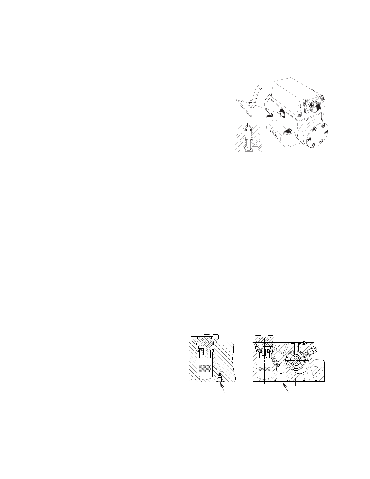
5. MECHANICAL NULL ADJUSTMENT
It is often desirable to adjust the flow null of a servovalve independent
of other system parameters.The “mechanical null adjustment” on the Moog
72 Series Servovalve allows at least ±20% adjustment of flow null. The
“mechanical null adjustor” is an eccentric bushing retainer pin, located above
the port designation on the valve body (see Figure 2) which, when rotated,
provides control of the bushing position. Mechanical feedback elements
position the spool relative to the valve body for a given input signal.Therefore,
a movement of the bushing relative to the body changes the flow null.
Tools and Equipment
a. Blade screwdriver
3
3
64,
b. Allen wrench set (3/32,7/
8,
/
/16)
c. No. 4-40 NC by 11/2inch screw,1/4 -28 UNF x 1 inch screw
d. Torque wrenches
e.3/8 inch offset box wrench
f. Tweezers
Figure 2
Mechanical Null Adjustment
6.PROCEDURE TO CONFIGURE A 72 SERIES SERVOVALVE
FOR EXTERNAL PILOT OPERATION (see figure 3)
a. Remove the set screw from the “X” port on the base of the valve using a
1/8” Allen wrench.
b. Thread a #2-56 screw into the O-Ring plug that is now visible and remove
it form the “X” port.
c. Remove the four socket head cap screws and lockwashers that retain the
cover plate for the field replaceable filter using a 5/32” allen wrench.
d. Use one of the screws to pull the filter and filter housing out of the filter
cavity of the body.The filter housing has two O-Rings on its O.D..The
housing will come part way out then stop after the second O-Ring passes
the internal relief in the body.At this time it may be easier to remove the
visible O-Ring and carefully pry the housing and filter out with two
opposing flat blade screw drivers, than to continue pulling on the screw. Be
careful not to damage the O-Ring groove.
e. A bore will be visible inside the body cavity where the O-Ring plug must
be inserted.
f. Retain the O-Ring plug with the set screw.
g. Re-install the filter and filter housing in the cavity.
h. Re-install the filter cover, retaining screws and lockwashers.Torque the
screws to 85-in-lbs.
Internal
External
Adjustment Procedure
Using a 3/8inch offset box wrench, loosen the self-locking fitting until the
null adjustor pin can be rotated. (This should usually be less than 1/2 turn).
DO NOT remove self-locking fitting. Insert a 3/32inch Allen wrench in null
adjustor pin. Use the 3/32Allen wrench to rotate the mechanical null adjustor
pin to obtain desired flow null.Torque self-locking fitting to 57 inch lbs.
Note:
Clockwise rotation of null adjustor pin produces open loop flow from port B to port A.
2 Moog • 72 Series Operation Instruction • RevE 04/07
Figure 3
X Port
Pressure Port
7. GENERAL SERVICING RECOMMENDATIONS
a. Disconnect electrical lead to servovalve.
b. Relieve hydraulic system of residual pressure.
c. Remove servovalve.
Page 3

8.TROUBLESHOOTING CHART
The following troubleshooting chart list potential troubles encountered, probable causes, and remedies.
Potential Trouble
Servovalve does not follow input command
signal. (Actuator or components are
stationary or creeping slowly.)
Poor response. (Servovalve output lags
electrical command signal).
Output flow obtained from one control
port only. (Actuator is hardover,or
hydraulic motor is rapidly rotating.No
response to electrical command signal.)
Low flow gain. (Failure to meet high rate or
rapid traverse speeds.)
High threshold. (Jerky, possible oscillatory
or “hunting” motion in closed loop system.)
High Null Bias. (High input current required
to maintain hydraulic cylinder or motor
stationary.)
Figure 4
Field
Replaceable
Filter
Probable Cause
1. Open coil assembly or open coil leads.
2. Plugged inlet filter element.
Partially plugged filter element.
1. Plugged inlet orifices.
2. Plugged inlet filter element.
3. Plugged hydraulic amplifier assembly.
4. Jammed spool.
Shorted coil assembly.
“Sticky” spool
1. Incorrect null adjustment
2. Partially plugged inlet orifice assembly.
3. Partially plugged filter element.
4. Partially plugged nozzle.
Torque Motor
Assembly
(cover not shown)
Pilot Stage Filter
(in Nozzle Block)
Filter Plug
Inlet Orifice
Assembly
Filter Housing
O-Rings
Filter Tube
Remedy
1. Return to factory.
2. Replace filter element.
Replace filter element and check for dirty
hydraulic fluid in system.
1. Return to factory.
2. Replace filter element.
3. Return to factory.
4. Return to factory.
Return to factory.
Clean bushing and spool assembly.
1. Readjust null
2. Return to factory.
3. Replace filter element and check for dirty
hydraulic fluid in system.
4. Return to factory.
Table 1. Replacement Parts
Part Description Qty. Part Number
72 Series Filter Replacement Kit 1 B52555RK099K001
Base O-Rings 4 -42082-040
Filter Housing O-Rings (I) 2 -42082-039
External Pilot Supply and Field
Replaceable Filter Internal O-Ring (I) 1 -42082-013
Filter Plug O-Rings (I) 2 -42082-060
Inlet Orifice O-Rings (I) 2 -42082-059
Pilot Stage Filter Tube (I) 1 -23020
Field Replaceable Filter (I) 1 -22050
Motor Cap Gasket (1) 1 -24509
(I) Included in Filter Replacement Kit.
9. FIELD REPLACEABLE FILTER ASSEMBLY REPLACEMENT
a. Remove four socket head cap screws and lockwashers on filter cover
using a 5/32inch Allen wrench. Remove filter cover plate. Use 1/4 inch-28
screw to pull filter plug out.
b. Remove O-Rings from filter plug and filter.
c. Inspect filter for foreign material and discard.
d. Install O-Rings on filter plug and inside filter.
e. Install filter, filter plug and cover plate.Torque screw to 85 inch-pounds.
10. PILOT STAGE FILTER REPLACEMENT
a. Remove torque motor cover leaving all electrical connections in place.
b. Locate Pilot Stage Filter in Nozzle Block of torque motor assembly.
Remove screws, lockwashers and cover plates from both sides.
c. Remove filter plugs from both sides of nozzle block and one (1) inlet orifice
assembly using a 2-56 screw which threads into the filter plug and inlet
orifice assembly. Use the 2-56 screw in the remaining inlet orifice assembly
to help remove filter tube. Note:These inlet orifice assemblies seat in
nozzle block and cannot go through bore during removal.
d. Remove O-rings from filter plugs and O-rings from inlet orifice assemblies.
e. Visually inspect filter orifice assemblies for damage or foreign matter.
f. Discard old O-rings and old filter tube.
g. Install new O-rings on filter plugs, and new O-rings on inlet orifices.
h. Install new filter tube back into torque motor nozzle block with one (1)
inlet orifice assembly inserted into filter tube. Follow with filter plug. Install
the other inlet orifice assembly and filter plug into the other end of filter
tube. Note: Inlet orifice assemblies and filter plugs are interchangeable.
i. Reinstall both cover plates with screws and lockwashers.Torque to 10+/-1
inch-pounds.
11. FUNCTIONAL CHECKOUT AND CENTERING
a. Install servovalve on hydraulic system or test fixture, but do not connect
electrical lead.
b. Apply required system pressure to servovalve and visually examine for
evidence of external leakage. If leakage is present and cannot be rectified
by replacing O-Rings, remove the discrepant component and return for
repair or replacement.
Note: If the system components are drifting or hardover, adjust
the mechanical null of the servovalve.
c. Connect electrical lead to servovalve and check phasing in accordance
with system requirements.
12.AUTHORIZED REPAIR FACILITIES
Moog does not authorize any facilities other than Moog or Moog
subsidiaries to repair its servovalves. It is recommended you contact Moog at
(716) 652-2000 or visit www.moog.com/worldwide to locate your closest Moog
repair facility. Repair by an independent (unauthorized) repair house will result
in voiding the Moog warranty and could lead to performance degradation or
safety problems.
Moog • 72 Series Operation Instruction • RevE 04/07 3
Page 4

3.05
[77.5]
4.06
[103.1]
3.28
[83.3]
.28
[7.1]
2.75
[69.9]
3.69
[93.7]
6.70
[170.2]
5.15
[130.8]
4.48
[113.8]
MAX
2.38 [60.5]
DIA TYP
1.37
[34.8]
PIN D
PIN C
PIN A
PIN B
1.50
[38.1]
FIELD REPLACEABLE
FIRST STAGE FILTER
.86
[22.0]
1.73
[43.9]
2.26
[57.4]
2.03
[51.6]
1.81
[46.0]
2.24
[56.9]
OPTIONAL
MAGNETIC
NULL ADJUST
4 MOUNTING HOLES
.406 [10.31] THRU
LOCATING PIN
1.437
[36.50]
2.875
[73.03]
3.375
[85.73]
1.687
[42.85]
.25 [6.4]
PRESS
MECHANICAL
NULL ADJUST
3.62 MAX
[92.0]
72 SERIES INSTALLATION AND OPERATION INSTRUCTION
M
M
M
M
4X .397 THRU
VALVE MOUNTS
ON THIS MANIFOLD
SURFACE
PRESSURE PORT
RETURN PORT
CONTROL PORT B
5.00
2.50
CONTROL PORT A
4X .375-16 UNC-2B THD
.013
4.250
2.125
2.000
1.000
1.000
2.000
4.250
2.125
2.875
1.437
.750
PRESSURE PORT
1.687
.750
1.500
3.375
1.60
1.500
2
PORT PER SAE J1926
.4375-20 UNF-2B
DASH 4 STR THD O-RING
BOSS (.25 TUBE OD REF)
63
2.50
5.00
2.50
P
4X PORT PER SAE J1926
1.625-12 UN-2B
DASH 20 STR THD O-RING
BOSS (1.25 TUBE OD REF)
.0015
1.25
4 PL
.39 .30
.014
.593 .60
.250 AUXILIARY PILOT
.014
M
.014
4X .688
.014
5
NOTES
1. Fluid:
Industrial type petroleum base hydraulic
fluid, maintained to ISO DIS 4406 Code
14/11 recommended.
2. Operating Temperature Range:
-40˚F to 275˚F (-40˚C to 135˚C)
3 Valve Phasing:
Flow out port B results when Series
coils: B & C connected,A+, D-;
Parallel coils:A & C connected, B & D
connected A+, B-; Single coil:A+, B-, or
C+, D-.
4 Surface:
Surface to which valve is mounted
requires 63[ ] finish, flat within .002
[0.05] TIR.
5 Null Adjust:
Flow out port B results with clockwise
rotation of null adjust screw (3/32hex key).
6. Ports:
P, R,A & B: 0.625 [18.88] Diam.port ORings: 0.070 [1.78] section x 0.801
[20.34] I.D. (universal size -019).
Valves are supplied for either internal or
external pressurization of pilot stage
through Auxiliary Port: Aux. Port Diam;
0.213 [5.41].Aux. Port O-Ring: 0.070
[1.78] section x 0.364 [9.25] I.D.
(universal size -012).
∆∆
Figure 5
The products described herein are subject to change at any time without notice, including, but not limited to, product features, specifications, and designs.
4 Moog • 72 Series Operation Instruction • RevE 04/07
TYPICAL WIRING SCHEMATIC
ABCD
3
4
TJW
Moog is a registered trademark of Moog Inc. and its subsidiaries. Unless expressly indicated, all trademarks as indicated
herein are the property of Moog Inc. and its subsidiaries. For disclaimers, see www.moog.com/literature/disclaimers.
Moog Inc., East Aurora, NY 14052-0018
Telephone: +1-716-652-2000
Fax: +1-716-687-7910
Toll Free: +1-800 -272-MOOG
www.moog.com/industrial
©2007 Moog Inc. All changes are reserved.
CDS6211 RevE 500-286 0407
 Loading...