

Page 1
1.INTRODUCTION
This manual provides instructions and procedures necessary to install,
operate and troubleshoot the Moog 641 Series Proportional Control Valve.
Troubleshooting instructions are outlined so that the specific component(s)
suspected of failure can be identified.
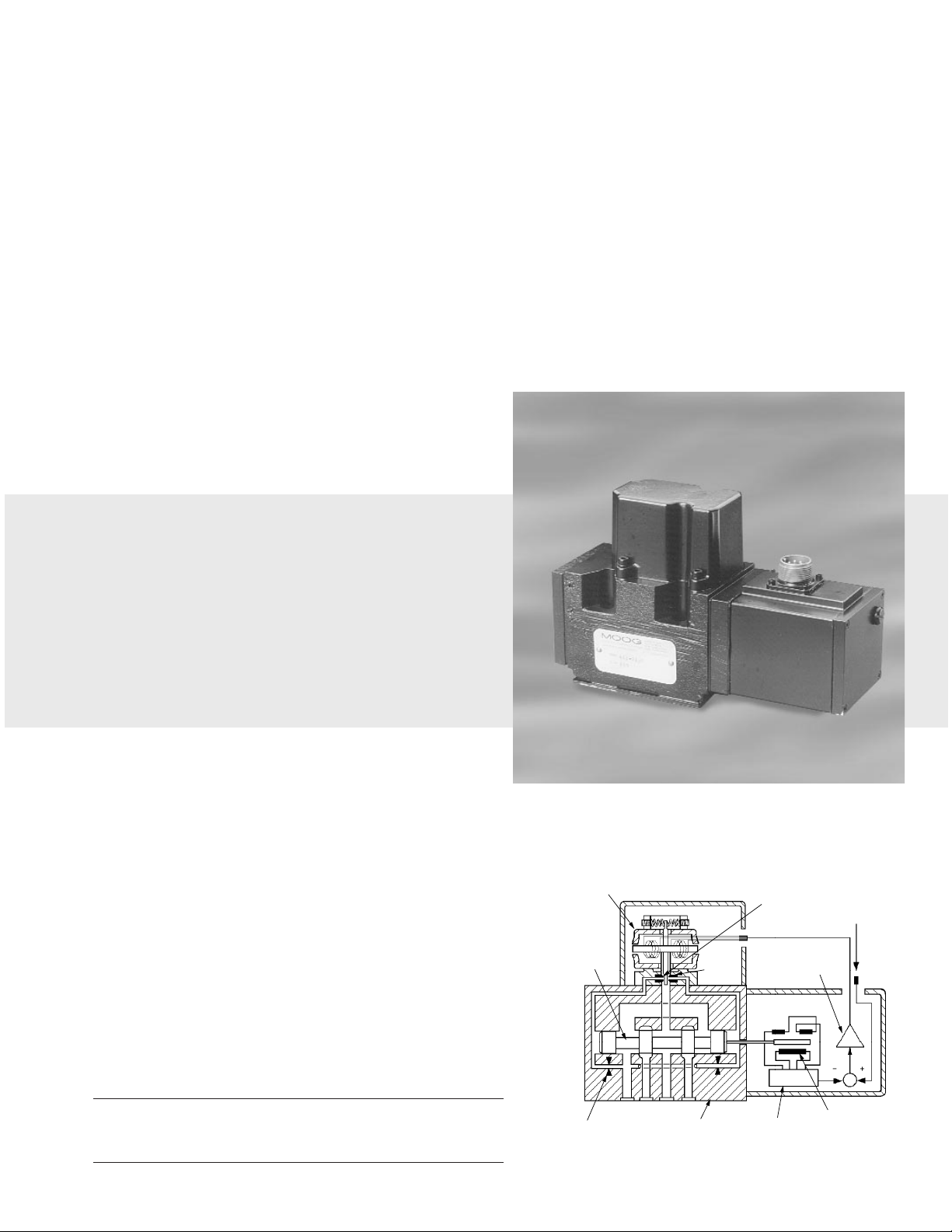
2. OPERATION
The Moog 641 Series proportional control valves are suitable for open
and closed loop position and velocity control systems where accelerations need
to be regulated.The 641 can be used like a directional solenoid valve or a
proportional valve while controlling ram or motor acceleration,deceleration
and velocity.
The 641 Series valves are two-stage devices consisting of a double nozzleflapper pilot stage and a sliding spool main stage.The position of the main stage
spool is measured by a non-contacting position transducer. On-board integrated
electronics provide closed-loop position control of the main stage spool.
The operation of the 641 Series valve is controlled by an electrical
command signal (VQS) provided to the integrated control electronics which
drives the pilot stage coils.The current sent from the electronics causes the
flapper to move toward one nozzle,diverting the pilot stage flow to one end of
the spool.The position transducer measures the position of the spool (VLI) and
produces a feedback voltage which is directed back to the control amplifier and
compared to the command voltage.The control amplifier then drives the pilot
stage until the command voltage and feedback voltage are equal,centering the
flapper between the nozzles which holds the spool at a position proportional to
the command signal.
m
641 Series Installation and
Operation Instruction
Proportional Control Valve
ELECTROHYDRA ULIC VAL VE CUT -A WA Y
CAUTION
DISASSEMBLY, MAINTENANCE, OR REPAIR OTHER THAN IN ACCORDANCE WITH THE
INSTRUCTIONS HEREIN OR OTHER SPECIFIC WRITTEN DIRECTIONS FROM MOOG WILL
INVALIDATE MOOG’S OBLIGATIONS UNDER ITS WARRANTY.
Figure 1 Moog Series 641
SINGLE STAGE
PILOT VALVE
SPOOL
PATB
INLET ORIFICE
NOZZLE
MAIN STAGE
FLAPPER
OSCILLATORDEMODULATOR
POSITION
CONTROL
AMPLIFIER
V
QS
V
LI
SPOOL POSITION
TRANSDUCER
(LVDT)
Page 2
3.HYDRAULIC SYSTEM PREPARATION
To prolong proportional control valve operational life and to reduce
hydraulic system maintenance,it is recommended that the hydraulic fluid be
kept at a cleanliness level of ISO Code 14/11 (NAS Class 5) or better.The most
effective filtration scheme incorporates the use of a kidney loop or “off-line”
filtration as one of the major filtration components. The filter for the “off-line”
filtration scheme should be a ß3≥75 filter for maximum effectiveness.
Upon system start-up,and prior to mounting the valve, the entire
hydraulic system should be purged of built-in contaminating particles by an
adequate flushing.The valve should be replaced by a flushing plate and the
hydraulic circuit powered up under conditions of fluid temperature and fluid
velocity reasonably simulating the normal operating conditions.Best possible
flushing is achieved if a 4 way/3 position directional control valve is fitted in
place of the proportional valve since,when the directional control valve is
actuated alternately,the downstream actuators are also flushed.New system
filters are installed during the flushing process whenever the pressure drop
across the filter element becomes excessive.The flushing processes should turn
over the fluid in the reservoir between fifty to one hundred times.
To maintain a clean hydraulic system, the filters must be replaced on a
periodic basis. It is best to monitor the pressure drop across the filter assembly
and replace the filter element when the pressure drop becomes excessive.In
addition to other filters installed in the hydraulic circuit,it is recommended that
a large capacity,low pressure ß3≥75 filter be installed in the return line.This
filter will increase the interval between filter element replacements and greatly
reduce system contamination.
4.INSTALLATION
The Moog 641 Series Proportional Control Valves may be mounted in any
position,provided the valve pressure,control,and return ports match respective
manifold ports.The mounting pattern and port location of the valve are shown
on Installation Drawing No.G2785. Apply a light film of oil to the mounting
screw threads and torque the screws to 90 inch-pounds.
Wire mating connector for desired coil configuration and polarity. Thread
connector to valve.
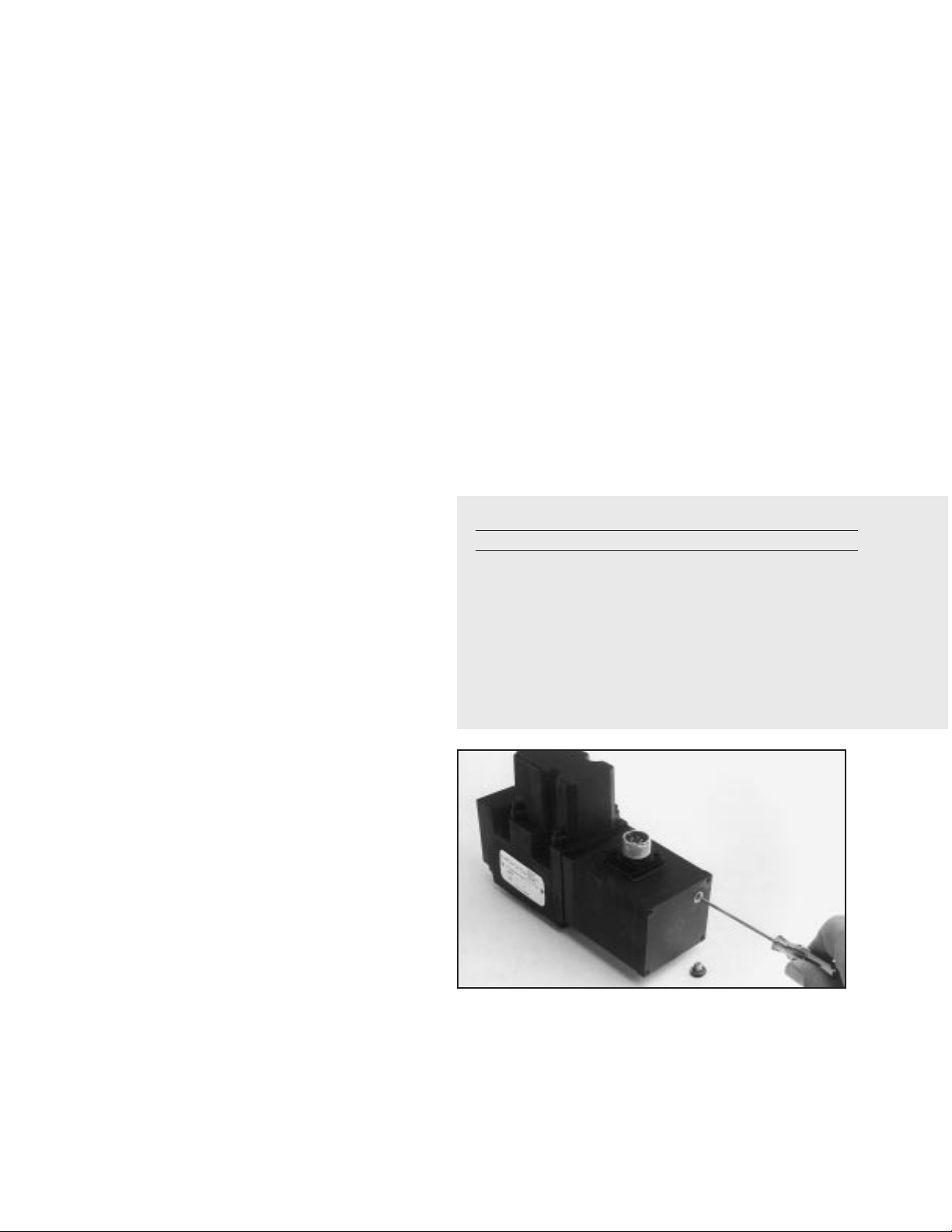
5.ELECTRICAL NULL ADJUSTMENT
It may be desirable to adjust the proportional valve for flow null
independent of other system parameters.The electrical null adjustment permits
convenient control set-ups.The electrical null adjust is a 4-turn potentiometer
located behind the pan head screw in the electronics housing.When turned,it
provides control of the spool position to obtain the desired flow null.
Adjustment Procedure
1. Verify that ±15 vdc power is supplied to the valve,and that the input signal
(pin D or E) is zero or grounded.
2. Using a flat blade screwdriver, remove the pan head screw (see Figure 2)
to permit adjustment of the potentiometer.
3. Using a flat blade screwdriver, adjust the potentiometer to obtain the
desired flow null. Note: Clockwise rotation of the potentiometer p
reduces flow out of control port A.
4. Replace the pan head screw.
5. Restore the input signal wiring for system operation.
Tools and Equipment:
a. Flat blade screwdriver
b. Allen wrench set (21/2,3,4,5 mm;3/16,7/32inch )
c. Volt-ohm-milliammeter
d. Torque wrenches,various,to meet reassembly requirements
6.GENERAL SERVICING RECOMMENDATIONS
a. Disconnect the electrical lead to the control valve.
b. Relieve the hydraulic system of residual pressure.
c. Remove the valve.
Table 1. Replacement Parts
Part Description Qty. Part Number
641 Series Filter Replacement Kit 1 B52555RK90K1
Base O-Rings 5 42082-4
Base O-Rings 2 42082-11
Filter O-Ring (1) 1 G2140-13-15
Filter Retainer Plate O-Ring (1) 1 G2140-17-20
Filter (1) 1 G2196-100
(1) Included in Filter Replacement Kit
Figure 2
Electrical Null Adjustment
Page 3

P otential Tr ouble
Proportional valve does not respond to
command signal
Output flow obtained from one control
port only. Limited or no response to
command signal.
High null bias (actuator drifts or hydraulic
motor slowly rotates when controller
returns to neutral).
Poor response (valve delays in returning to
neutral after controller is returned to
neutral).
Non-repeatability (valve fails to return to
neutral each time controller is returned to
neutral).
Probable Cause
1 Controller does not function
2.Open or miswired controller cable
3.Open connector lead or damaged
electronics board
4.Jammed spool
5.Filter completely plugged
1.Controller not functioning properly
2.Filter silted with contamination
3.Plugged inlet orifice assembly
4.Plugged torque motor
5.Jammed spool
6.Electrical null adjust adjusted hardover
1.Incorrect null adjustment
2.Filter silted with contamination
3.Partially plugged inlet orifice assembly
4.Partially plugged torque motor
5.Damaged electronics
1.Filter silted with contamination
2.Contamination in spool bore
1.Controller not functioning properly
2.Contamination in spool bore
3.Partially plugged torque motor assembly
Remedy
1.Replace controller
2.Replace/repair controller cable
3.Return to factory
4.Return to factory
5.Replace filter
1.Replace controller
2.Replace filter
3.Return to factory
4.Return to factory
5.Return ot factory
6.Readjust electrical null
1.Readjust electrical null
2.Replace filter
3.Return to factory
4.Return to factory
5.Return ot factory
1.Replace filter
2.Return to factory
1.Replace controller
2.Return to factory
3.Return to factory
7. TROUBLESHOOTING CHART
The following troubleshooting chart list potential troubles encountered,probable causes,and remedies.
8.FIL TER ASSEMBL Y REPLACEMENT
a. Using a 3 mm Allen wrench,remove the four (4) socket head capscrews
and lockwashers. Remove filter plate.
b. Remove,inspect and discard filter disc. Remove O-Ring from filter cavity
and retainer plate.
c. Install new O-Rings and filter. Install filter retainer using 4 socket head
capscrews.torque to 36 inch pounds.
9.FUNCTIONAL CHECKOUT AND CENTERING
a. Install the control valve in your hydraulic system or test fixture,but do not
connect electrical lead.
b. Apply required system pressure to the control valve and visually examine
for evidence of external leakage.If leakage is present and cannot be
rectified by replacing O-Rings,remove the discrepant component and
return for repair or replacement.
Note: If the system components are drifting or hardover,adjust
the electrical null of the control valve.
c. Connect electrical lead to control valve and check phasing in accordance
with system requirements.
10.AUTHORIZED REPAIR FACILITIES
Moog does not authorize any facilities other than Moog or Moog subsidiaries to
repair its servovalves.It is recommended you contact Moog at (716)655-3000
to locate your closest Moog repair facility.Repair by an independent
(unauthorized) repair house will result in voiding the Moog warranty and could
lead to performance degradation or safety problems.
Figure 3
Filter O-Ring
Filter
Filter Retainer Plate
Page 4

[54.00]
2.126
PIN E
PIN D
PIN C
PIN B
PIN A
PIN F
INSTALL SEAL WASHER
AND SCREW FOR
INTERNAL PILOT SUPPLY
8.74 MAX
[222.0]
2.75 MAX
[69.9]
[27.00]
1.063
3.85
[97.8]
[46.02]
1.812
[23.01]
.906
4.17
[105.9]
1.42
[36.1]
2.84
[72.1]
3.27
[83.1]
2.09 REF
[53.1]
5.11
[129.8]
3.00
[76.2]
SEAL WASHER AND SCREW SHOWN
INSTALLED FOR EXTERNAL PILOT SUPPLY
1.66
[42.2]
4 PLACES
ELECTRICAL NULL
ADJUSTMENT
2.36
[60.0]
1.52
[38.6]
3.28
[83.3]
.79
[20.0]
REMOVABLE
FILTER
COVER
.270 [6.86] DIA THRU
CBORE .437 [11.10] DIA
TO DEPTH SHOWN (1.66 REF)
4 PLACES
.008
M
ELECTRICAL
CONNECTOR
641 SERIES INSTALLATION AND OPERATION INSTRUCTION
CDS6381 REV B 500-314 1199
Moog Inc.,East Aurora,NY 14052-0018
Telephone: 716/655-3000
Fax:716/655-1803
Toll Free: 1- 800-272-MOOG
NOTES
STANDARD ELECTRICAL
CONFIGURATION
The products described herein are subject to change at any time without notice, including, but not limited to, product features, specifications, and designs.
1 Fluid:
Industrial type petroleum base hydraulic
fluid,maintained to ISO DIS 4406 Code
14/11 recommended.
2 Operating Temperature Range:
-4˚F to 175˚F (-20˚C to 80˚C)
3 Surface:
Surface to which valve is mounted
requires 63[ ] finish,flat within .002
[0.05] TIR.
4 Null Adjust:
Remove coverscrew.Clockwise rotation
of potentiometer increases flow out
port A.
T
63
A
PRESSURE PORT
CONTROL PORT B
CONTROL PORT A
1.94
.38
.38
5.00
2.12
3.51
2.13
5.00
4.250
4.250
VALVE MOUNTS ON THIS
MANIFOLD SURFACE
NOTE: CONTROL
PORT 'B' FARSIDE
PORT PER SAE J1926
1.3125-12 UN-2B DASH 16
STR THD O-RING BOSS
(1.00 OD TUBE REF)
4 PLACES
PORT PER SAE J1926
.4375-20 UNF-2B DASH 4
STR THD O-RING BOSS
(.25 OD TUBE REF)
.438 DIA
4 PLACES
.406 DIA THRU
CBORE .609 DIA x .62 DEEP
4 MOUNTING HOLES
.970
5 PL
2.126
1.063
.406
.406
2.190
.437
.552
.937
.250-20 UNC-2B THD
4 VALVE MTG HOLES
.007
M
.002
1.480
2.125
.594
.843
1.812
RETURN (TANK)
PORT
NOTE: SUPPLY PRESSURE
PORT FARSIDE
.125 DIA PILOT
PRESSURE PORT
[LOCATION NOT PER
ISO 4401 PATTERN]
.014
M
.014
M
∆∆
Figure 4
+3V (200mA MAX)
A
-3V (200mA MAX)
B
COMMON
C
INPUT SIGNAL (±10V)
D
E
SPOOL POSITION OUTPUT (±1.5VDC)
F
POSITIVE SIGNAL AT PIN 'D' RESULTS IN FLOW OUT PORT 'A'.
}
POWER
SUPPLY
+15V (200mA MAX)
A
-15V (200mA MAX)
B
COMMON
C
D
INPUT SIGNAL (±10V)
E
SPOOL POSITION OUTPUT (±1.5VDC)
F
POSITIVE SIGNAL AT PIN 'E' RESULTS IN FLOW OUT PORT 'B'.
}
POWER
SUPPLY
Industrial Controls Division
 Loading...