

Page 1

Manual and Warranty
Page 2

i
TABLE OF CONTENTS
INTRODUCTION . . . . . . . . . . . . . . . . . . . . . 1
About the User Manual . . . . . . . . . . . . . . . . . . . . . . . . . . . 1
FIRMWARE UPDATES . . . . . . . . . . . . . . . 2
Latest Features in Firmware Version r10817 . . . . . . . . . . . . . . 2
OVERVIEW . . . . . . . . . . . . . . . . . . . . . . 3
Technical Specications . . . . . . . . . . . . . . . . . . . . . . . . . . 3
General . . . . . . . . . . . . . . . . . . . . . . . . . . . . . . . . . . . . 3
Dimensions . . . . . . . . . . . . . . . . . . . . . . . . . . . . . . . . . 3
Hardware Specications . . . . . . . . . . . . . . . . . . . . . . . . . 3
Software Specications . . . . . . . . . . . . . . . . . . . . . . . . . . 4
What's in the Box . . . . . . . . . . . . . . . . . . . . . . . . . . . . . . . 6
The Monster® GO-DJ™ Device . . . . . . . . . . . . . . . . . . . . . . 6
Monster® GO-DJ™ Accessories . . . . . . . . . . . . . . . . . . . . . . 6
Front of the Monster® GO-DJ™ . . . . . . . . . . . . . . . . . . . . . . 7
Right Side of the Monster® GO-DJ™ . . . . . . . . . . . . . . . . . . . 7
Upper Side of the Monster® GO-DJ™ . . . . . . . . . . . . . . . . . . 7
Back Side of the Monster® GO-DJ™ . . . . . . . . . . . . . . . . . . . 7
Lower Side of the Monster® GO-DJ™ . . . . . . . . . . . . . . . . . . 7
Buttons . . . . . . . . . . . . . . . . . . . . . . . . . . . . . . . . . . . . . 8
Beat LED . . . . . . . . . . . . . . . . . . . . . . . . . . . . . . . . . . . . 12
In the Power OFF State . . . . . . . . . . . . . . . . . . . . . . . . . 12
In the Power ON State . . . . . . . . . . . . . . . . . . . . . . . . . . 12
In the Standby State . . . . . . . . . . . . . . . . . . . . . . . . . . . 12
Information Bar . . . . . . . . . . . . . . . . . . . . . . . . . . . . . . . . 13
GETTING STARTED . . . . . . . . . . . . . . . . 14
How to Turn On . . . . . . . . . . . . . . . . . . . . . . . . . . . . . . . . 14
How to Charge . . . . . . . . . . . . . . . . . . . . . . . . . . . . . . . . 14
Screen Modes . . . . . . . . . . . . . . . . . . . . . . . . . . . . . . . . . 14
Available On-Screen Information . . . . . . . . . . . . . . . . . . . . . 14
Minimum Mode . . . . . . . . . . . . . . . . . . . . . . . . . . . . . . 14
Advanced Mode . . . . . . . . . . . . . . . . . . . . . . . . . . . . . . 15
How to Switch Between Screens . . . . . . . . . . . . . . . . . . . . . 16
Minimum Mode . . . . . . . . . . . . . . . . . . . . . . . . . . . . . . 16
Advanced Mode . . . . . . . . . . . . . . . . . . . . . . . . . . . . . . 16
How to Connect to a Sound System . . . . . . . . . . . . . . . . . . . 17
VOLUME CONTROL . . . . . . . . . . . . . . . . 18
Master Volume – Minimum Mode . . . . . . . . . . . . . . . . . . . . . 18
Master Volume – Advanced Mode . . . . . . . . . . . . . . . . . . . . 18
Summary of Volume Control Functions . . . . . . . . . . . . . . . . . 19
HOW TO PREPARE MUSIC . . . . . . . . . . . 20
How to Load Files . . . . . . . . . . . . . . . . . . . . . . . . . . . . . . . 20
How to Connect to a Computer with the Connector Cable . . . . . 20
How to Use the SD Card Drive . . . . . . . . . . . . . . . . . . . . . . . 20
Compatible File Types . . . . . . . . . . . . . . . . . . . . . . . . . . . . 20
Intelligent Stream Technology . . . . . . . . . . . . . . . . . . . . . . . 20
Automatic File Analysis . . . . . . . . . . . . . . . . . . . . . . . . . . . 21
Automatic File Conversion . . . . . . . . . . . . . . . . . . . . . . . . . 21
Page 3

ii
TABLE OF CONTENTS
FILE BROWSER SCREEN . . . . . . . . . . . . 22
How to Search Files . . . . . . . . . . . . . . . . . . . . . . . . . . . . . 22
Storage and Sound Input Selection . . . . . . . . . . . . . . . . . . . 22
Memory Storage Selection . . . . . . . . . . . . . . . . . . . . . . . 22
Sound Input Selection . . . . . . . . . . . . . . . . . . . . . . . . . . 22
Directories and Files . . . . . . . . . . . . . . . . . . . . . . . . . . . . .23
How to Sort Files . . . . . . . . . . . . . . . . . . . . . . . . . . . . . 23
How to Select a File . . . . . . . . . . . . . . . . . . . . . . . . . . . 23
Using the FUNCTION Knob . . . . . . . . . . . . . . . . . . . . . . . 23
Using the Touch Screens . . . . . . . . . . . . . . . . . . . . . . . . 24
Icons in the File Selection Screen . . . . . . . . . . . . . . . . . . . 24
File Properties Window . . . . . . . . . . . . . . . . . . . . . . . . . 25
How to Load a Track with the Digital Turntables . . . . . . . . . . 25
Unanalyzed Files . . . . . . . . . . . . . . . . . . . . . . . . . . . . . 26
Unsupported Files . . . . . . . . . . . . . . . . . . . . . . . . . . . . 26
File Browser Window for Recorded Files . . . . . . . . . . . . . . . 26
Playlists . . . . . . . . . . . . . . . . . . . . . . . . . . . . . . . . . . . . . 27
How to Create a New Playlist . . . . . . . . . . . . . . . . . . . . . . 27
How to Use the Input Keyboard . . . . . . . . . . . . . . . . . . . . 27
Function Knob . . . . . . . . . . . . . . . . . . . . . . . . . . . . . . . 27
Touch Screen . . . . . . . . . . . . . . . . . . . . . . . . . . . . . . . 27
How to Add and Remove Items from a Playlist . . . . . . . . . . . 27
How to Change Track Order in a Playlist . . . . . . . . . . . . . . . 28
How to Delete an Item in a Playlist . . . . . . . . . . . . . . . . . . 28
How to Play Tracks via the Playlist . . . . . . . . . . . . . . . . . . . 28
How to Search Playlist Tracks . . . . . . . . . . . . . . . . . . . . . . 29
How to Use Playlists with the AutoDJ . . . . . . . . . . . . . . . . 29
How to Edit Playlists . . . . . . . . . . . . . . . . . . . . . . . . . . . 29
Sorting Playlists . . . . . . . . . . . . . . . . . . . . . . . . . . . 29
Playlist Edit Menu . . . . . . . . . . . . . . . . . . . . . . . . . . 30
How to Clear All Playlists . . . . . . . . . . . . . . . . . . . . . 30
History . . . . . . . . . . . . . . . . . . . . . . . . . . . . . . . . . . . . . 30
Display of History . . . . . . . . . . . . . . . . . . . . . . . . . . . . . 31
How to Play Files via History . . . . . . . . . . . . . . . . . . . . . . 31
Reset Menu . . . . . . . . . . . . . . . . . . . . . . . . . . . . . . . . . . 32
Dedicated Folders for Samples . . . . . . . . . . . . . . . . . . . . . . 33
DIGITAL TURNTABLES SCREEN . . . . . . . 34
How to Control Tracks . . . . . . . . . . . . . . . . . . . . . . . . . . . .34
Arc Selector . . . . . . . . . . . . . . . . . . . . . . . . . . . . . . . . 34
How to Use the Function Knob in the Arc Selector . . . . . 34
Hot-Cue Points . . . . . . . . . . . . . . . . . . . . . . . . . . . 34
Arc Selector and Corresponding Functions . . . . . . . . . . 36
Digital Turntables . . . . . . . . . . . . . . . . . . . . . . . . . . . . . . 37
Pitch Bend Mode . . . . . . . . . . . . . . . . . . . . . . . . . . . . . 37
Search Mode . . . . . . . . . . . . . . . . . . . . . . . . . . . . . . . . 37
O Mode . . . . . . . . . . . . . . . . . . . . . . . . . . . . . . . . . . 38
Loop Adjust Mode . . . . . . . . . . . . . . . . . . . . . . . . . . . . 38
Tap Mode . . . . . . . . . . . . . . . . . . . . . . . . . . . . . . . . . . 39
Break Mode . . . . . . . . . . . . . . . . . . . . . . . . . . . . . . . . 39
Search Mode . . . . . . . . . . . . . . . . . . . . . . . . . . . . . . . . 40
Beat Radar . . . . . . . . . . . . . . . . . . . . . . . . . . . . . . . . . . .41
Tempo Controllers . . . . . . . . . . . . . . . . . . . . . . . . . . . . . .42
Tempo Slider . . . . . . . . . . . . . . . . . . . . . . . . . . . . . . . . 42
Auto-Sync Switch . . . . . . . . . . . . . . . . . . . . . . . . . . . . . 42
BPM Window . . . . . . . . . . . . . . . . . . . . . . . . . . . . . . . . 42
Pitch Lock Switch . . . . . . . . . . . . . . . . . . . . . . . . . . . . . 42
Page 4

iii
TABLE OF CONTENTS
EQUALIZER SCREEN . . . . . . . . . . . . . . . 43
Basic Operations of the Equalizer . . . . . . . . . . . . . . . . . . . . . 43
Touch Panel Operations . . . . . . . . . . . . . . . . . . . . . . . . . 43
Analog Control Operation . . . . . . . . . . . . . . . . . . . . . . . 43
EQ Crossfader Mode . . . . . . . . . . . . . . . . . . . . . . . . . . . . . 44
Gain Operation . . . . . . . . . . . . . . . . . . . . . . . . . . . . . . . .45
Gain Slider Control . . . . . . . . . . . . . . . . . . . . . . . . . . . . 45
Saving and Loading Gain Levels . . . . . . . . . . . . . . . . . . . . 45
Gain on File Loading . . . . . . . . . . . . . . . . . . . . . . . . . . . . . 46
SAMPLERS SCREEN . . . . . . . . . . . . . . . 47
Musical Pad . . . . . . . . . . . . . . . . . . . . . . . . . . . . . . . . . . 47
Touchscreen Operation . . . . . . . . . . . . . . . . . . . . . . . . . 47
Analog Operation . . . . . . . . . . . . . . . . . . . . . . . . . . . . . 47
Loading and Assigning Samples . . . . . . . . . . . . . . . . . . . . . 48
Assigning Samples to Specic Pads . . . . . . . . . . . . . . . . . . 48
Assignment Priorities . . . . . . . . . . . . . . . . . . . . . . . . . . 49
Synthesizer Keyboard . . . . . . . . . . . . . . . . . . . . . . . . . . . .50
Octave Button . . . . . . . . . . . . . . . . . . . . . . . . . . . . . . . 50
Instrument Window . . . . . . . . . . . . . . . . . . . . . . . . . . . 50
Adding Instruments to the Synthesizer Keyboard . . . . . . . . . 51
Assigning Samples to Specic Positions . . . . . . . . . . . . . . . 51
Assignment Priorities . . . . . . . . . . . . . . . . . . . . . . . . . . 52
Beat Sequencer . . . . . . . . . . . . . . . . . . . . . . . . . . . . . . . . 53
Touch Panel Operation . . . . . . . . . . . . . . . . . . . . . . . . . 53
Function Knob Operation . . . . . . . . . . . . . . . . . . . . . . . . 53
Assigning Samples to the Beat Sequencer . . . . . . . . . . . . . 54
Assigning Samples to Specic Positions . . . . . . . . . . . . . . . 54
Assignment Priorities . . . . . . . . . . . . . . . . . . . . . . . . . . 55
External Inputs . . . . . . . . . . . . . . . . . . . . . . . . . . . . . . . . 56
Assign Audio from Line-In to the Digital Turntable . . . . . . . . 56
Assign MIC to the Turntable . . . . . . . . . . . . . . . . . . . . . . 56
Limited Functionality of Line-In and MIC . . . . . . . . . . . . . . 56
Volume Control of External Inputs . . . . . . . . . . . . . . . . . . 57
Real-Time BPM Analysis . . . . . . . . . . . . . . . . . . . . . . . . . 57
OPTIONS SCREEN . . . . . . . . . . . . . . . . 58
CONTROL Tab . . . . . . . . . . . . . . . . . . . . . . . . . . . . . . . . . 58
CONTROL (1) . . . . . . . . . . . . . . . . . . . . . . . . . . . . . . . . 58
Crossfader mode . . . . . . . . . . . . . . . . . . . . . . . . . . 58
Invert crossfader . . . . . . . . . . . . . . . . . . . . . . . . . . 58
Tempo slider range . . . . . . . . . . . . . . . . . . . . . . . . . 58
Pitch bend depth . . . . . . . . . . . . . . . . . . . . . . . . . . 58
CONTROL (2) . . . . . . . . . . . . . . . . . . . . . . . . . . . . . . . . 59
Volume knob sensitivity . . . . . . . . . . . . . . . . . . . . . . 59
Reset EQ on load . . . . . . . . . . . . . . . . . . . . . . . . . . 59
Reset tempo on load . . . . . . . . . . . . . . . . . . . . . . . . 59
Reset gain on load . . . . . . . . . . . . . . . . . . . . . . . . . 59
CONTROL (3) . . . . . . . . . . . . . . . . . . . . . . . . . . . . . . . . 60
Switch loop range . . . . . . . . . . . . . . . . . . . . . . . . . 60
Reset EQ on load . . . . . . . . . . . . . . . . . . . . . . . . . . 60
Slip mode for BREAK . . . . . . . . . . . . . . . . . . . . . . . . 60
Sync Beat Sequencer to music . . . . . . . . . . . . . . . . . . 60
Delay FX time . . . . . . . . . . . . . . . . . . . . . . . . . . . . 60
CONTROL (4) . . . . . . . . . . . . . . . . . . . . . . . . . . . . . . . . 61
Resume last session on boot . . . . . . . . . . . . . . . . . . . 61
Dot counter in Browser represents . . . . . . . . . . . . . . . 61
Remember history . . . . . . . . . . . . . . . . . . . . . . . . . 61
Page 5

iv
DEVICE Tab . . . . . . . . . . . . . . . . . . . . . . . . . . . . . . . . . . . 62
DEVICE (1) . . . . . . . . . . . . . . . . . . . . . . . . . . . . . . . . . 62
Microphone type . . . . . . . . . . . . . . . . . . . . . . . . . . 62
Line in amp volume . . . . . . . . . . . . . . . . . . . . . . . . 62
Send main sound to HP . . . . . . . . . . . . . . . . . . . . . . 62
Beat LED . . . . . . . . . . . . . . . . . . . . . . . . . . . . . . . 62
DEVICE (2) . . . . . . . . . . . . . . . . . . . . . . . . . . . . . . . . . 63
Backlight brightness . . . . . . . . . . . . . . . . . . . . . . . . 63
Backlight o timer . . . . . . . . . . . . . . . . . . . . . . . . . 63
Wake up / shutdown on USB power . . . . . . . . . . . . . . 63
Auto power o timer . . . . . . . . . . . . . . . . . . . . . . . . 63
REC Tab . . . . . . . . . . . . . . . . . . . . . . . . . . . . . . . . . . . . . 64
Recording . . . . . . . . . . . . . . . . . . . . . . . . . . . . . . . 64
Available recording time . . . . . . . . . . . . . . . . . . . . . 64
Current recording time . . . . . . . . . . . . . . . . . . . . . . 64
AutoDJ Tab . . . . . . . . . . . . . . . . . . . . . . . . . . . . . . . . . . . 65
AutoDJ . . . . . . . . . . . . . . . . . . . . . . . . . . . . . . . . 65
Playing order . . . . . . . . . . . . . . . . . . . . . . . . . . . . . 65
Transition timing . . . . . . . . . . . . . . . . . . . . . . . . . . 65
Mix style . . . . . . . . . . . . . . . . . . . . . . . . . . . . . . . 65
SYSTEM Tab . . . . . . . . . . . . . . . . . . . . . . . . . . . . . . . . . . 66
SYSTEM (1) . . . . . . . . . . . . . . . . . . . . . . . . . . . . . . . . . 66
Date / Time . . . . . . . . . . . . . . . . . . . . . . . . . . . . . . 66
USB storage mode . . . . . . . . . . . . . . . . . . . . . . . . . 66
SYSTEM (2) . . . . . . . . . . . . . . . . . . . . . . . . . . . . . . . . . 66
Firmware Version . . . . . . . . . . . . . . . . . . . . . . . . . . 66
In SD / In Internal drive . . . . . . . . . . . . . . . . . . . . . . 66
Reset all options to default . . . . . . . . . . . . . . . . . . . . 66
SYSTEM (3) . . . . . . . . . . . . . . . . . . . . . . . . . . . . . . . . . 67
FIRMWARE . . . . . . . . . . . . . . . . . . . . . . 68
Firmware Update . . . . . . . . . . . . . . . . . . . . . . . . . . . . . . .68
Mandatory Firmware Update . . . . . . . . . . . . . . . . . . . . . . . 68
Preparation for Mandatory Firmware Update . . . . . . . . . . . . 68
Starting the Recovery Menu . . . . . . . . . . . . . . . . . . . . . . 68
Firmware Recovery Menu . . . . . . . . . . . . . . . . . . . . . . . . 69
TABLE OF CONTENTS
Page 6

1
About the User Manual
For your convenience, a digital copy of the Monster® GO-DJ™ User
Manual is included in the rmware. You can nd a copy in the Monster®
GO-DJ™ by searching the “GO-DJ Manual” directory.
You can also download the latest version of the Monster
® GO-DJ
™
User
Manual from the ocial website.
The ocial website of the Monster
® GO-DJ
™
is as follows:
http://monsterproducts.com/godj
INTRODUCTION
Page 7
2
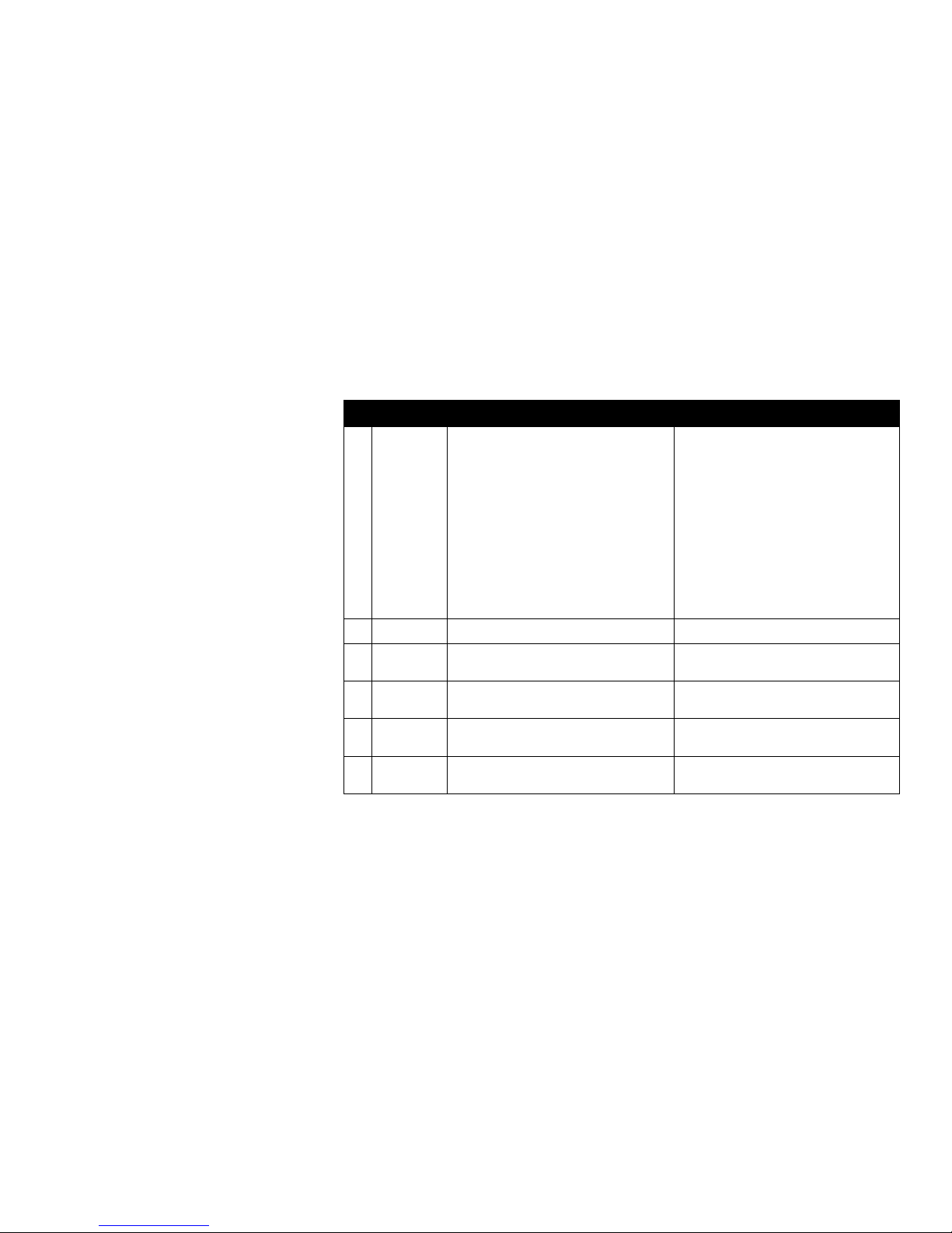
FIRMWARE UPDATES
Equalizer Screen
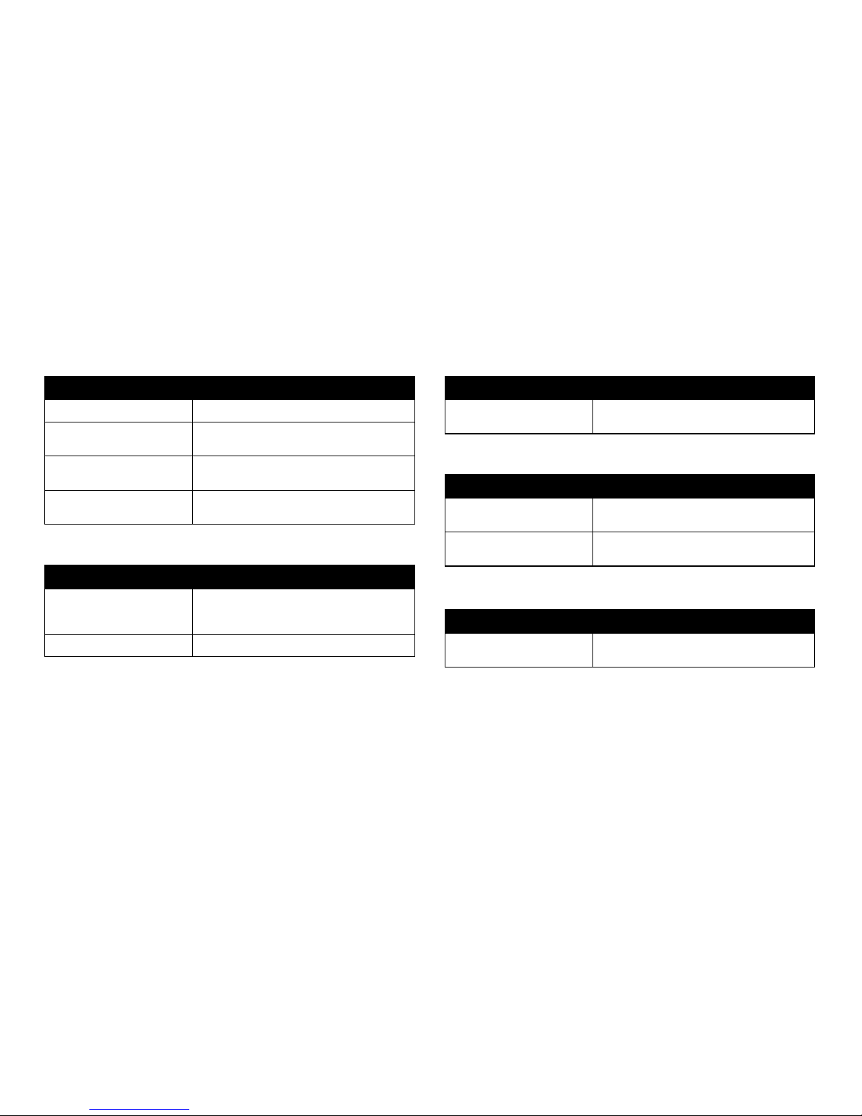
Latest Features in Firmware Version r10817
File Browser Screen
Update Description
Playlist available Create, edit and play custom playlists.
History available The Monster® GO-DJ™ also keeps a detailed play
history of the tracks.
Reset menu option available Reset the menu on les, directories and other
storage drives.
Visual markers for play
repetition available
Visual dots are used to mark les that indicate play
repetition history.
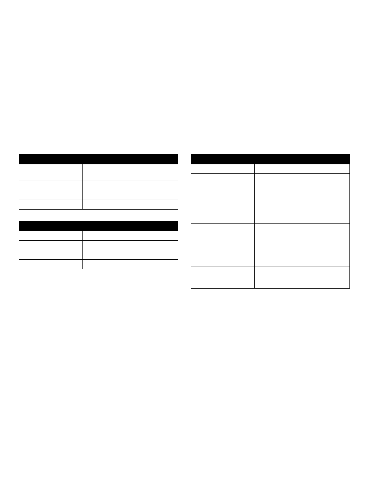
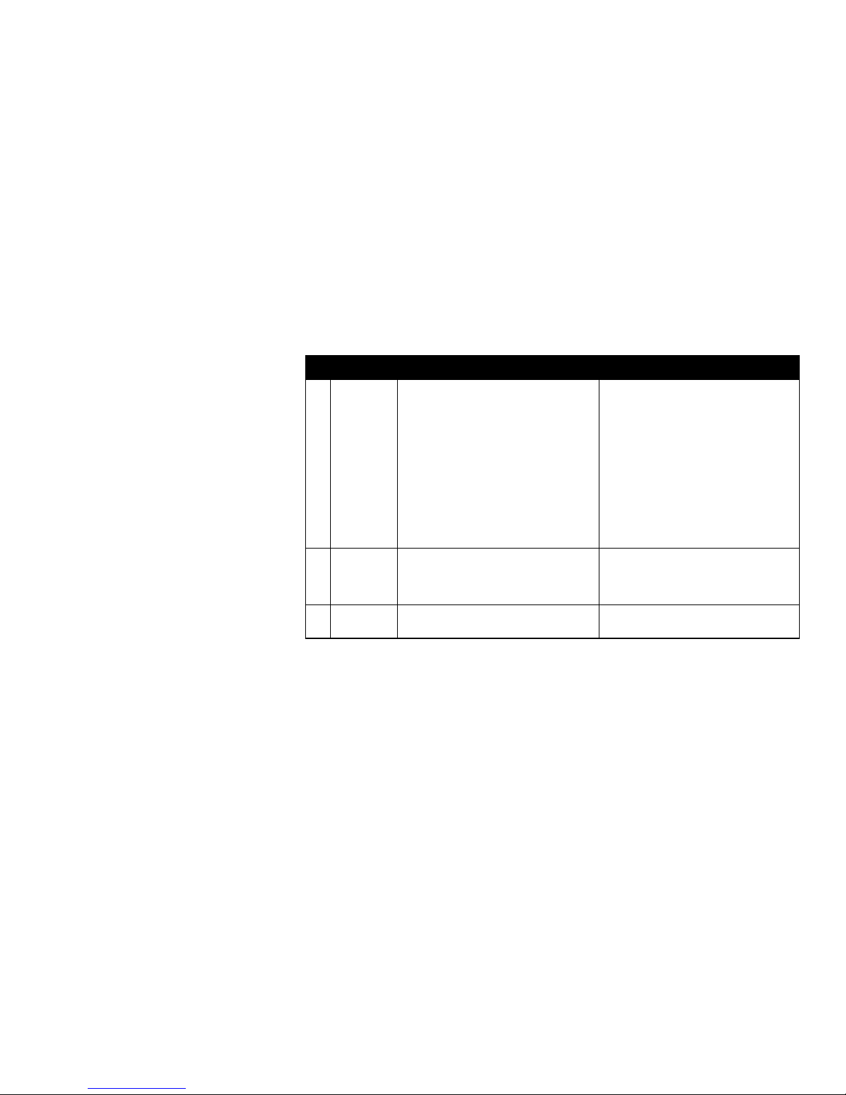
Update Description
Gain Slider available Gain control is available via the Gain Slider in
the Equalizer Screen.
Update Description
Tempo Slider updated Touch and hold the tempo slider on the Digital
Turntable screen while rotating the FUNCTION
knob to ne-tune tempo (BPM) changes.
Beat Radar updated The Beat Radar motion is extended.
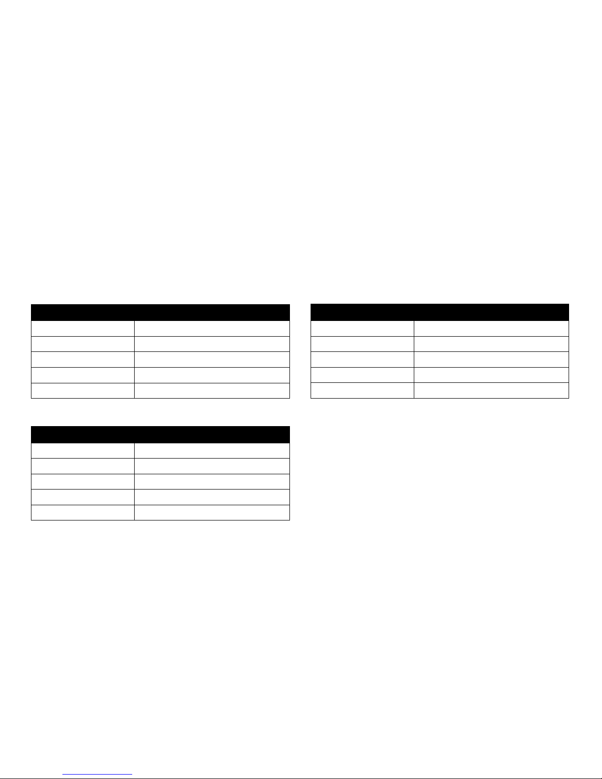
Update Description
Touchscreen Keyboard
Synthesizer available
Touchscreen keyboard synthesizer with
customizable sound banks is available.
Sample assignment updated Extended functions for sample assignments
are available.
Update Description
Beat position following available The beat sequencer follows the beat position
of the track.
Digital Turntable Screen
Musical Pad Screen
Beat Sequencer Screen
Page 8
3
OVERVIEW
Technical Specications
General
Display Dual Touch Screen
320×240 resolution color display (×2)
Battery Internal Li-Polymer Battery
Energy Saver Supports SLEEP mode
Compatibility iOS devices, Android devices, PC, Mac
Hardware Specications
Sound Card Integrated (Built In)
Battery (Internal
Li-Polymer Battery)
Charging Time: 8 hours
Battery Life Max: 12 hours
Input Terminals MIC ×1 (¹ inch)
HEADPHONE ×1 (¹ inch)
AUXILIARY LINE IN ×1 (¹ inch)
Output Terminals MASTER LINE OUT ×1 (¹ inch)
Sound I/O 3.5mm Stereo Jack ×4
(Line-out, Headphones, Line-in, Microphone)
Line-out : 1.0 Vrms
Headphones : 1.0 Vrms
THD : 0.015% (L-OUT, 1KHz), 0.009% (H.P. OUT, 1KHz)
S/N Ratio : 100dB (L-OUT), 100dB (H.P. OUT)
Storage Internal Flash Memory
(2GB for user space, 1GB for recording space)
SD Card Slot ×1 (up to 32GB)
Dimensions
Weight 10.09 ounces (286 grams)
Length 9.84 inches (250 mm)
Width 2.59 inches (66 mm)
Height 0.6 inches (16.8 mm)
Page 9
4
Technical Specications (continued)
OVERVIEW
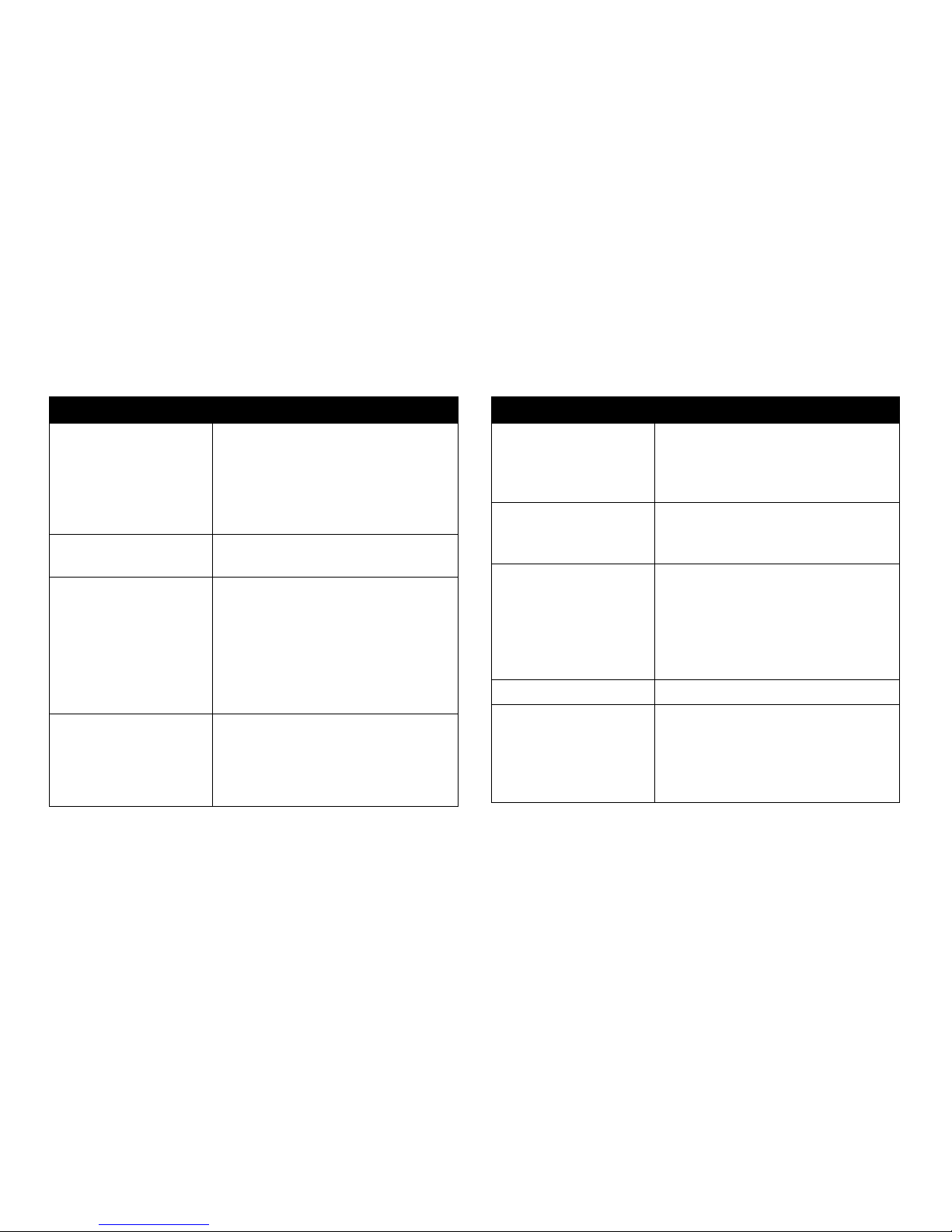
Software Specications
File Manager General directory based le system
(support up to 10,000 les)
Sort by File Name
Sort by Track Name
Sort by BPM
Alphabetical Search
Supported File Format MP3, WAV for playback
WAV for recording
Player Two individual players with CUE,
PLAY/PAUSE, LOOP and TEMPO control
Hot-cue memory
9-range Loop Control (¹ to 32-beat)
Tempo (BPM) Control: (-10.00% ~ +10.00%)
with/without master pitch
Automatic synchronization
(BPM adjustment and beat matching)
Recorder Records Line-out sound to the internal
memory in WAV format
Recording Time: 2 hours maximum
Records up to 100 les (up to 2 hours)
Make digital copies to SD card
Software Specications (continued)
Turntable/Platter Operation Scratch
Pitch Bend
Loop Range Adjustment
Cue Point Search
Volume Control Master Volume
Track Volume
Crossfader
Sound Eects Phaser
Flanger
Delay
Filter
Roll
Bitcrusher
3-Band Visual Equalizer Low, Middle, High
Music Pad One Shot Sample Pad ×8 per channel (×2)
Loop Sample Pad ×8 per channel (×2)
Drone Sample Pad ×8 per channel (×2)
Stock samples included
Upload custom samples
Page 10
5
Technical Specications (continued)
OVERVIEW
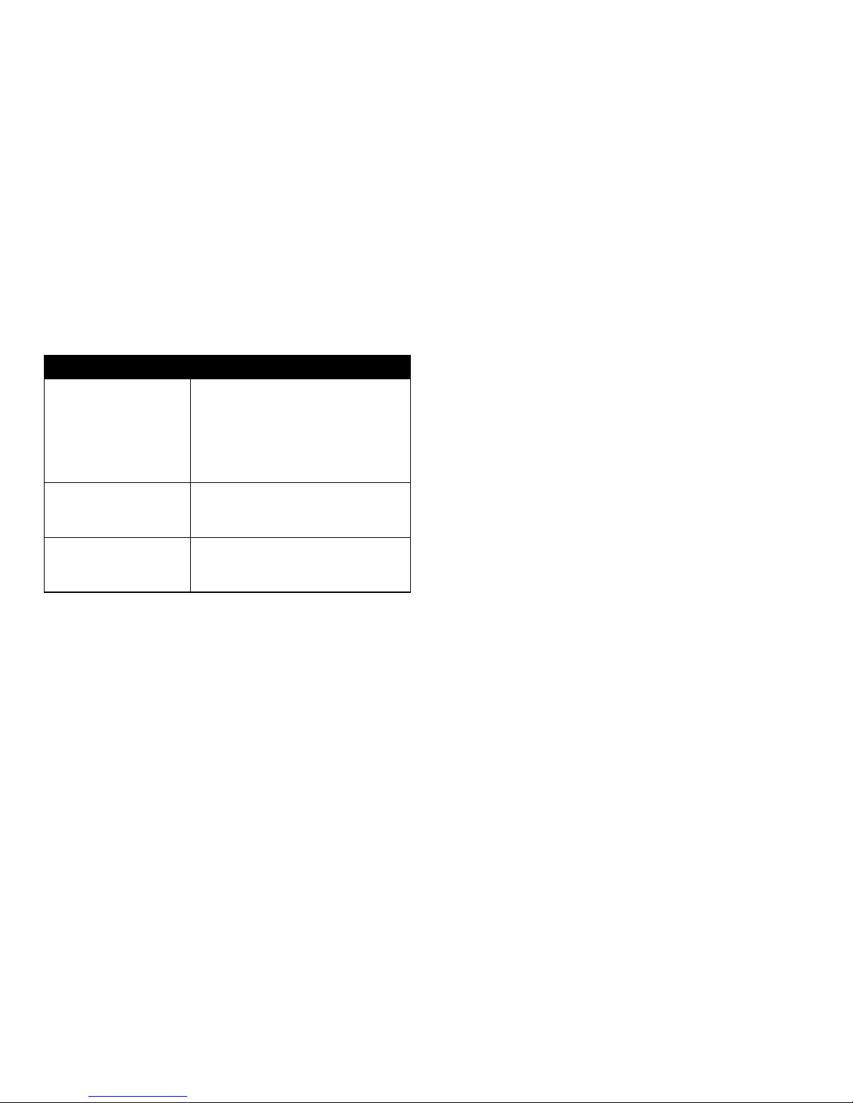
Software Specications (continued)
4-Beat Step Sequencer Editable preset pattern ×4 per channel (×2)
User pattern storage ×4 per channel (×2)
18 instrument sources
BPM controller
Stock samples included
Upload custom samples
AUTO DJ Normal Mix Mode
Simple Mix Mode
Advanced Mix Mode
Options Crossfader curve control
Backlight brightness control
Beat LED switch
Page 11

6
WHAT’S IN THE BOX
The Monster® GO-DJ™ Device
Monster® GO-DJ™ Accessories
USB Connector Cable
Use your USB Cable Connector to charge your Monster
® GO-DJ
™
with the
Monster® GO-DJ™ Power Adapter. You can also use your Monster® GO-DJ™
Connector Cable to connect your Monster® GO-DJ™ to your computer
(PC or Apple) to both charge and transfer data.
Monster® GO-DJ™ Power Adapter
Use with your Monster
® GO-DJ
™
USB Connector Cable to charge your
Monster® GO-DJ™. For international use, we have included a variety of
international plug adapters.
OVERVIEW
Page 12

7
Front of the Monster® GO-DJ
™
a. Touch panel for Track-A
b. Touch panel for Track-B
Right Side of the Monster® GO-DJ
™
c. SD Card Slot
d. Power Button
Upper Side of the Monster® GO-DJ
™
e. USB Connector (MINI-B USB)
f. LINE OUT
g. LINE IN
Back Side of the Monster® GO-DJ
™
h. Reset Button
Lower Side of the Monster® GO-DJ
™
i. Microphone Jack
j. Headphone (Monitor)
Output Jack
OVERVIEW
a b
c
d
e f g
h
i j
Page 13

8
Buttons
The buttons are arranged to replicate the layout of a traditional DJ setup
for two turntables and a mixer.
Button 1 Volume for Tracks A and B
Button 2 FX Level
Button 3 FX Select
Button 4 Analog Controller
Button 5 Play/Pause
Button 6 Cue
Button 7 Crossfader
Please be aware that these are multi-function and multi-layered buttons,
also known as “soft keys.” They have dierent functions depending on how
they are handled. There are four ways to adjust the function of these knobs.
The Secondary Function is triggered when an analog button or knob is
pressed down.
• Turning the knob
• Click the knob by pressing down
• Click and turn by pressing and holding down and turning the knob
• Long Press
OVERVIEW
1
4
5 66 5
1
4
2
3
7
Page 14

9
# Button Primary Function Secondary Function
1 VOLUME-A Turn the button in order to toggle the volume
of Track-A. The track level is indicated by the
LED meter.
Send Track-A to Headphones:
Click to route the audio from Track-A to the
headphones. Click again to choose to send
the audio to either the left side, the right side
or both sides of the headphones.
Microphone Volume Control: Press, hold and
turn the button while turning to toggle the
microphone volume.
1 VOLUME-B Turn the button in order to toggle the volume
of Track-B. The track level is indicated by the
LED meter.
Send Track-B to Headphone:
Click to route the audio from Track-B to the
headphones. Click again to choose to send
the audio to either the left side, the right side
or both sides of the headphones.
Headphone Volume:
Press, hold and turn the button to toggle the
headphone volume. The level is indicated by
the LED meter.
Buttons (continued)
OVERVIEW
1
4
5 66 5
1
4
2
3
7
Page 15
10
# Button Primary Function Secondary Function
2 FX LEVEL Turn the FX LEVEL button to change the level
of the selected (or grouped) FX function(s).
Note: Some FX functions have secondary
functions. Please refer to the “EFFECTS” section
of the manual.
Master Volume:
When the FX SELECT button is placed on the
last option (ALL FX OFF), turn the FX LEVEL
button to toggle the master volume.
Dynamic FX Routing:
When the FX SELECT button is placed on the
last option (ALL FX OFF), press, hold and turn
the FX LEVEL knob to choose what channel to
route the selected FX function(s) to (VOLUME-A,
VOLUME-B, or both tracks).
3 FX SELECT Turn and click to select one or more eects (FX). None
4 FUNCTION-A Use clicks and turns to control dierent analog
functions on each screen for Track-A.
None
4 FUNCTION-B Use clicks and turns to control dierent analog
functions on each screen for Track-B.
None
5 PLAY/PAUSE Press to play or pause the track loaded to the
Digital Turntable on Track-A.
None
5 PLAY/PAUSE Press to play or pause the track loaded to the
Digital Turntable on Track-B.
None
Buttons (continued)
OVERVIEW
1
4
5 66 5
1
4
2
3
7
Page 16
11
# Button Primary Function Secondary Function
6 CUE Press to set a cue point on Track-A. Press and hold to begin playing Track-A from
the cue point. Releasing the CUE button will
stop playback and return Track-A to the cue
point, unless PLAY is pressed.
6 CUE Press to set a cue point on Track-B. Press and hold to begin playing Track-B from
the cue point. Releasing the CUE button will
stop playback and return Track-B to the cue
point, unless PLAY is pressed.
7 CROSSFADER Slide back and forth to adjust the balance
between Track-A and Track-B.
None
Buttons (continued)
OVERVIEW
1
4
5 66 5
1
4
2
3
7
Page 17
12
Beat LED
Two Beat LED lights, located right above the crossfader, indicate the internal
status of the Monster® GO-DJ™. The following tables describe what the Beat
LED lights indicate:
In the Power OFF State
Beat LED Light Status Description
Turned O Not charging
Blinking Red Charging (Battery level < 90%)
Blinking Green Charging (Battery level > 90%)
Blinking Purple Analyzing Files
Blinking Orange Converting Files
Beat LED Light Status Description
Turned O Track paused
Blinking Blue Track playing
Blinking Red Synchronizing track
Blinking Green Track synchronized
Blinking Purple Analyzing les
Beat LED Light Status Description
Blinking Light Blue Track paused
Blinking Blue Track playing
Blinking Red Synchronizing track
Blinking Green Track synchronized
Steady Purple Analyzing les
In the Power ON State
In the Standby State
OVERVIEW
Page 18
13
Information Bar
An information bar is located at the top of both screens. The information bar
displays current information regarding track names, icon notications, track
progress bar, and track time information.
Track Progress Bar
The Progress Bar displays the playback position of the loaded track. By tapping
and dragging the tip of the progress bar, you can jump to a desired playback
position. This is also referred to as a “needle drop.”
Please note: The progress bar can be tapped and dragged in the Digital
Turntable screen.
Time Information
The Time Information window displays the time information of the loaded track.
By tapping the Time Information window, you can toggle between Time Left
and Elapsed Time.
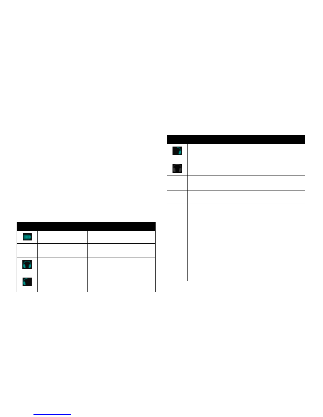
Icon Messages
The following table is the key to the graphic icons in the Monster
® GO-DJ
™
:
Icons Function Description
Battery Level Displays the current power level of the
internal battery.
Digital Turntable Shortcut Tap to automatically go to the Digital
Turntable screen.
Headphone Monitor Toggle Displays that the current track on the
respective channel is cued and playing
on both sides of the headphones.
Headphone Monitor Toggle Displays that the current track on the
respective channel is cued and playing
on the Left side of the headphones.
Icons Function Description
Headphone Monitor Toggle Displays that the current track on the
respective channel is cued and playing
on the Right side of the headphones.
Headphone Monitor Toggle No output to the headphones.
Headphone Monitor Toggle Audio from the LINE-OUT jack (master
mix) is output to the Headphones jack.
FX Function (PH) Displays that the FX SELECT has been
set to Phaser.
FX Function (FL) Displays that the FX SELECT has been
set to Flanger.
FX Function (DL) Displays that the FX SELECT has been
set to Delay.
FX Function (VCF) Displays that the FX SELECT has been
set to Filter.
FX Function (RL) Displays that the FX SELECT has been
set to Roll.
FX Function (BC) Displays that the FX SELECT has been
set to Bit Crusher.
FX Function (OFF) Toggle to turn o all FX.
OVERVIEW
Page 19

14
Screen Modes
The Monster® GO-DJ™ has two dierent screen modes: Minimum and Advanced.
In Minimum Mode there are 3 screens of functionality. In Advanced Mode there
are six screens of functionality
The default setting for the Monster
® GO-DJ™ is Advanced Mode. To switch
to Minimum Mode, go to the Options Screen, select System and toggle the
option for Minimum Mode. The Monster® GO-DJ™ system will then reboot in
Minimum Mode.
Available On-Screen Information
Minimum Mode
In Minimum Mode The Monster
® GO-DJ
™
has three (3) screens
• Combination of minimum Digital Turntable and minimum File
Browser Screen
• Volume Control
• Options Screen
GETTING STARTED
How to Turn On
To turn on the Monster® GO-DJ™, press and hold the power button for one (1)
to two (2) seconds. The power button is located at the right side of the Monster®
GO-DJ™. If the battery power is too low for the Monster® GO-DJ™ to power on,
you will see a message that states “Low Battery.”
Power States
The Monster
® GO-DJ
™
has three power states: ON, OFF, and Standby. These are
switched with the power button.
Please note: In the Standby state, the displays turns o and the operations
with a touch panel, buttons and knobs are all invalid. However, music playback
does not stop, and the crossfader operation is still valid.
How to Charge
When the Monster® GO-DJ™ battery power level is low, you can charge the
battery power by either of these two methods:
1. Charge by connecting to the Monster
® GO-DJ
™
Power Adapter.
2. Charge by connecting the Monster
® GO-DJ
™
Connector Cable to a USB
power source, such as a computer.
Power OFF
Power button push
(more than 1 second)
Power button push
(more than 1 second)
Power ON
Power button
Standby
Page 20

15
• Digital Turntable
• Equalizer
• Musical Pad
• Beat Sequencer
• Options
• File Browser Screen
Advanced Mode
The Monster
® GO-DJ
™
has six (6) screens in Advanced Mode:
GETTING STARTED
Page 21

16
How to Switch Between Screens
Minimum Mode
To access the minimum File Browser in the Digital Turntable screen, click the
section of the screen that says “Touch Here” on the left. To return to the Digital
Turntable, either swipe left across the screen, or click on the gray bar to the
right of the File Browser.
To access the Volume Control / Options Screen from the Digital Turntable
Screen, either swipe left across the Monster
® logo at the bottom of the screen,
or click on the Options icon in the upper left hand corner of the screen.
To access the Digital Turntable Screen from the Volume Control / Options Screen,
either swipe right across the Monster
® logo at the bottom of the screen, or click
on the Digital Turntable icon in the upper left hand corner of the screen.
Advanced Mode
In Advanced Mode, there are two ways to switch between the six
dierent screens:
1. Touch the arrows on the lower left or right hand corner of the screen.
2. Swipe left or right across the Monster
® logo at the bottom of the screen.
Helpful Hint
To quickly return to the Digital Turntable, you can tap the Digital
Turntable icon ( ), which is located on the upper left hand corner
of the screens.
GETTING STARTED
Page 22

17
GETTING CONNECTED
How to Connect to a Sound System
Connect your Monster® GO-DJ™ to a sound system with speakers by connecting
the appropriate cable to the LINE OUT jack of your Monster® GO-DJ™.
Connect headphones or earbuds to the PHONES jack.
For a simple sound check, you can connect your headphones or earbuds to
the LINE OUT jack and test to see if the sound is outputting properly.
You can also keep your headphones or earbuds connected to the LINE OUT
jack to monitor the Master Out.
To speakers
To headphones
Line Out
Phones
Page 23
18
VOLUME CONTROL
Control the sound levels by using the VOLUME-A button, FX LEVEL button and
the VOLUME-B button.
Master Volume — Minimum Mode
In Minimum Mode, you can change the level of the Master Volume by swiping
to the Minimum Mode control screen (located to the right of the Minimum
Mode Digital Turntable Screen) and changing the Master Volume level.
Master Volume — Advanced Mode
Here’s how to adjust volume In the Advanced Mode.
1. Rotate the FX Select button to the last placement (turn clockwise until
the last LED light), which is also the ALL FX OFF position.
2. Use the FX LEVEL button to change the Master Volume level, which
is signied by the LED lights that surround the FX LEVEL button.
Track-A Volume
To change the volume level of Track-A, rotate the VOLUME-A button.
The level is indicated by the LED lights that surround the VOLUME-A button.
Track-B Volume
To change the volume level of Track-B, rotate the VOLUME-B button.
The level is indicated by the LED lights that surround the VOLUME-B button.
Headphone Volume
To change the Headphone Volume, press down, hold and rotate the
VOLUME-B button. The level is indicated by the LED lights that surround
the VOLUME-B button (while the button is pressed down).
To choose which track is monitored in the headphones, click the VOLUME-A
button to listen to Track-A; click the VOLUME-B button to listen to Track-B.
Clicking on the VOLUME-A and VOLUME-B buttons will send you through
dierent headphone monitor modes (i.e., send sound to right channel, send
sound to left channel, send sound to both right and left channels, do not
send sound to any channels).
Please note that the headphone volume level is applied to both tracks at the
same time.
Microphone Volume
To change the level of the Microphone Volume, press down, hold and rotate
the VOLUME-A button. The level is signied by the LED lights that surround the
VOLUME-A button (while the button is pressed down).
Please note that the microphone volume level is applied to both tracks at the
same time.
Musical Pad Volume
While on the Music Pad screen, rotate the corresponding button (FUNCTION A
button for Music Pad on Track-A; FUNCTION B button for Music Pad on Track-B).
Page 24

19
Summary of Volume Control Functions
The operation and function control of various volumes are summarized
in the following table. Please refer to the section on External Inputs for
detailed information regarding the microphone (MIC) volume and line-in
(LINE-IN) volume.
VOLUME CONTROL
Volume Type How to Operate Volume-Aected Applied To
Master Volume 1. Rotate FX SELECT knob to nal position (right most).
2. Change volume by rotating FX LEVEL knob.
Track-A and Track-B (combined) Output to LINE OUT
Headphone Volume Press, hold and rotate VOLUME-B knob Track-A and Track-B (combined) Output to PHONES
Microphone Volume Press, hold and rotate VOLUME-A knob MIC
Track-A and Track-B (combined)
Input from MIC
Line-in Volume 1. Navigate to Options Screen.
2. Use slider control for “Line In Amp Volume.”
Track-A and Track-B (combined) Input from LINE-IN
Track Volumes
(Track-A and Track-B)
Rotate the VOLUME-A knob to control the volume of Track-A.
Rotate the VOLUME-B knob to control the volume of Track-B.
Track-A and Track-B (individually) Output of the Digital Turntable(s) to LINE OUT
Optional: In the Options Screen, when the “Send Main Sound
to HP” option is ON, the output to PHONES is aected.
Musical Pads
Volumes
1. Navigate to Musical Pads Screen.
2. Rotate the FUNCTION-A knob to control the volume of
the Musical Pads on Track-A.
Rotate the FUNCTION-B knob to control the volume of
the Musical Pads on Track-B.
Track-A and Track-B (individually) Output of the Musical Pads samplers (i.e., Musical Pads, Digital
Keyboard Synthesizer, Beat Sequencer) to LINE OUT
Optional: In the Options Screen, when the “Send Main Sound
to HP” option is ON, the output to PHONES is aected.
Beat Sequencer
Volume
1. Navigate to the Beat Sequencer Screen.
2. Use the slider control (located on the right side of the Beat
Sequencer) to control the volume of the Beat Sequencer.
Track-A and Track-B (individually) Output of the Beat Sequencer to LINE OUT
Optional: In the Options Screen, when the “Send Main Sound
to HP” option is ON, the output to PHONES is aected.
Page 25

20
HOW TO PREPARE MUSIC
How to Load Files
There are three (3) ways to load music into your Monster® GO-DJ™:
1. Computer and Connector Cable
2. SD Card Drive
3. Monster
® Intelligent Stream Technology.
How to Connect to a Computer with the Connector Cable
Connect the Monster® GO-DJ™ with a PC or Mac using the Connector Cable.
Connect the USB jack to the computer and the Mini-USB jack into the top of
the Monster® GO-DJ™.
Once connected, go to the “Options” screen on your Monster
® GO-DJ
™
, select
the “System” tab, and turn ON the “USB Storage Mode.”
Once the “USB Storage Mode” connection has been established, your
computer will recognize four (4) external drives:
• GO-DJ™ Drive: The “GO-DJ Drive” directory is located in the internal
memory, where you can store your music and audio samples.
• GO-DJ™ Recorded: The “GO-DJ Recorded” directory is located in the
Monster
® GO-DJ
™
internal memory, where you can store your recorded
track(s) on the Monster® GO-DJ™.
• GO-DJ™ Manual: The “GO-DJ Manual” directory is located in the Monster
®
GO-DJ™ internal memory, where the ocial Monster® GO-DJ™ manual(s)
are conveniently stored for your reference.
• SD Card: Your computer will recognize the volume label of the SD card
that is inserted into the Monster
® GO-DJ
™
SD card drive, where you can
store your music and audio samples.
Once you have nished transferring your les, you can end the connection
by tapping on the “Cancel” button. This will disconnect the Monster
® GO-DJ
™
from your computer.
Note: It is recommended to properly eject the Monster
® GO-DJ
™
drive from your
computer rst before turning o the connection on your Monster® GO-DJ™.
How to Use the SD Card Drive
You can store your music and audio les on an SD memory card. To use your
SD memory card with your Monster® GO-DJ™, insert the SD memory card into
the Monster® GO-DJ™ SD card slot, which is located on the right side of the
Monster® GO-DJ™. You can preload the SD memory card with audio les,
such as your music and sample les, for playback with the Monster® GO-DJ™.
Note: The Monster
® GO-DJ
™
recognizes up to a maximum of 32 GB for SD
car memory.
Compatible File Types
The Monster® GO-DJ™ can recognize and playback two (2) digital le formats:
MP3 (44.1 kHz stereo, up to 320 kbps) and WAV (44.1 kHz, 16-bit, stereo). The
Monster® GO-DJ™ does not recognize le names that start with a period/dot (.).
Intelligent Stream Technology
The Monster® GO-DJ™ is compatible with third-party audio devices that can
be connected with analog audio cables via the LINE IN jack.
Compatible third-party audio devices include, but are not limited to, the
following: iOS devices (e.g., iPod, iPhone, iPad), Mac OS devices (e.g., Macbook
Pro), Android devices (e.g., Android smartphones, Android tablets), PC, musical
instruments, digital multimedia players, etc.
Once you connect the third-party audio device with the Monster
® GO-DJ
™
via
the LINE IN jack, swipe to the File Browser Screen. In the main directory, also
known as parent, choose the LINE IN option. You can choose the LINE IN input
by either double-tapping on the touchscreen or using the corresponding
FUNCTION knob.
Page 26

21
HOW TO PREPARE MUSIC
Once the LINE IN device is properly loaded, the streaming audio will be loaded
on the corresponding Digital Turntable.
Press PLAY to begin playback.
Once you are playing the streaming audio, you can use the Digital Turntable
functions (i.e., Scratch, Loop), Tri-Band Equalizer functions, Musical Pad
functions and Beat Sequencer functions.
Automatic File Analysis
When the Monster® GO-DJ™ recognizes new les, the Monster® GO-DJ™ will
start analyzing the les automatically. During the analysis of the le(s), you
may experience some slowing down in the processing, but you can still play
back music and audio les that have already been analyzed. The Beat LED
light will turn purple to signify that the Monster® GO-DJ™ is in the process of
analyzing the new le(s). When the purple Beat LED light turns o, the le(s)
have been analyzed completely.
Automatic File Conversion
The Monster® GO-DJ™ has dedicated folders in the internal memory drive
for the Musical Pad Samplers screen. The Musical Pad Samplers screen includes
three digital sampler devices: the Musical Pad Sampler, the Digital Keyboard
Synthesizer and the Beat Sequencer.
When you place your sample les in the corresponding folder, the uploaded
le will be assigned to the corresponding Musical Pad Sampler device.
Please note that the sample le should be a WAV le format (8–48 kHz,
8–24 bit). The uploaded sample le will then be converted into a uniform
WAV format (44.1 kHz, 16 bit). When le conversion is necessary, the Monster
®
GO-DJ™ might take some time to boot. In order to cancel or postpone the
le conversion, press down on the FUNCTION knob.
Page 27

22
Sound Input Selection
FILE BROWSER SCREEN
How to Search Files
The File Browser Screen is where you can select the sound source, such as
audio les, playlists, or Line In (for Intelligent Stream Technology), and load
the audio track to the corresponding Digital Turntable.
Storage and Sound Input Selection
The main, also known as parent, directory of the File Browser Screen is used
for Memory Storage Selection and Sound Input Selection.
Memory Storage Selection
Icons Description
The “SD Drive” directory is displayed with this icon. The “SD Drive” directory
is displayed only when an SD memory card is present in the SD memory
card drive. You can read, browse, load and edit your les in the SD card.
The “GO-DJ Drive” directory is displayed with this icon. The “GO-DJ Drive”
directory is located in the internal memory of the Monster® GO-DJ™. You
can read, browse, load and edit your les located in the internal drive.
The “GO-DJ Rec” directory is displayed with this icon. The “GO-DJ Rec”
directory is located in the internal memory of the Monster® GO-DJ™.
This is the dedicated folder for recorded audio les (when used with the
Record function found in the Options Screen).
Icons Description
The “LINE IN” icon is displayed when a jack is inserted into the LINE IN
terminal. Select this sound input option by double tapping or using
the FUNCTION knob. The sound input from the LINE IN terminal will be
assigned to the corresponding Digital Turntable.
The “MIC TO TURNTABLE” icon is displayed when a jack is inserted into
the MIC terminal. Select this sound input option by double tapping or
using the FUNCTION knob. The sound input from the MIC terminal will be
assigned to the corresponding Digital Turntable.
Page 28

23
Directories and Files
How to Sort Files
You can change the method of sorting les by touching the tabs located
at the top of the File Browser Screen.
You can toggle the sort order direction by touching the triangle icon
(
or ) located at the upper left hand corner of the directory browser.
FILE BROWSER SCREEN
How to Select a File
You can select les using two (2) methods: analog operation with the FUNCTION
knob and touch screen operation.
Using the FUNCTION Knob
To select a le using the FUNCTION knob, rotate the FUNCTION knob to move
the File Selector and select the le you need.
When the desired le is selected, press the FUNCTION knob. This will open the
File Properties window.
Conrm that you want to load the le. Choose “Cancel” otherwise.
When you select a directory, usually displayed with a folder icon, pressing the
FUNCTION knob will open and enter the selected directory.
Page 29

24
Using the Touch Screens
• Swipe Up or Down: You can swipe vertically to scroll through the File
Browser Window vertically.
• Tap: You can touch (tap) the screen to select a le or directory.
• Double Tap: You can double tap the screen to open the File Properties
window. Conrm that you want to load the le. Choose “Cancel” otherwise.
When you select a directory, double tapping will open and enter the
selected directory.
• Swipe Left: Swiping to the left is the same function as the double tap.
• Swipe Right: You can swipe to the right to exit from the current directory.
Icons in the File Selection Screen
The File Browser Screen displays icons by the le names to display specic
information about the les.
Icons Description
The white dots can indicate two pieces of information: how many times
or how recently the le is played. You can select which information is
displayed by changing the corresponding option in the Options Screen.
Depending on what setting you choose, the white dots will mean one
of the following:
• If “Play Count” is selected in the Options Screen:
The number of dots corresponds to the number of times that the track
has been played. The maximum number of dots is four (4). If a track is
played more than four (4) times, the Play Count will remain four (4).
• If “Passed Time” is selected in the Options Screen:
The number of dots indicates the recentness of play, specically showing
how much time has passed since the track was last played.
The following is the key to the information:
4 Dots: Less than 30 minutes has passed since the track was last played.
3 Dots: Less than 2 hours have passed since the track was last played.
2 Dots: Less than 24 hours have passed since the track was last played.
1 Dots: Less than 10 days have passed since the track was last played.
0 Dots: More than 10 days have passed since the track was last played.
Note: In order to calculate the time that has passed since the last playback,
Play History is required. You can turn on Play History by toggling the
“Remember History” option in the CONTROL(4) tab of the Options Screen.
Please note that if you change the date or time on the SYSTEM(1) tab of
the Options Screen, the change is reected in the displayed information
of the time that has passed since the last playback.
Icons Description
The le or track is loaded on the Digital Turntable on Track-A.
The le or track is loaded on the Digital Turntable on Track-B.
The le or track is loaded on BOTH Digital Turntables on Track-A and Track-B.
Hot-cue points are set on the le or track. The color and number of
bars correspond to the real data that the user sets (actual number of
hot-cue points).
FILE BROWSER SCREEN
Page 30

25
File Properties Window
The File Properties Window is opened when you select a le and open it
by pressing the FUNCTION knob, swiping (to the left) over the lename or
double-tapping the le name.
The following information is displayed in the File Properties Window:
• Track Name, Artist, Album: The information displayed in these categories
is read from the MP3 tag. If the WAV or MP3 le does not have a valid tag,
then lename represent is displayed instead.
• Length: This information displays the length of the track.
• BPM: This information displays the tempo or Beats Per Minute (BPM) of
the track.
• Last Played: This information displays when the le was last loaded or
played. This is only active when the “Remember History” option is turned
ON, which can be done in the Options Screen.
• “X” Times: This information displays the total play count of the track. This
is only active when the “Remember History” option is turned ON, which
can be done in the Options Screen.
How to Load a Track with the Digital Turntables
To load a le on the Digital Turntables, rst select the le in the File Browser Screen.
When you open the related File Properties window, choose “Load” to load the
selected track to the Digital Turntable. You can select “Load” using the touch
screen or FUNCTION knob.
To use the FUNCTION knob:
• Rotate: Rotate the FUNCTION knob to change the highlighted selection.
• Press on Load: Press the FUNCTION knob on the “Load” option to load the
selected le to the Digital Turntable.
• Press on Cancel: Press the CANCEL knob to close the File Properties window.
You cannot load an Unanalyzed File or an Unsupported File.
FILE BROWSER SCREEN
Page 31

26
Unsupported Files
When you try to open or load an unsupported le, its BPM is shown as 0 (or “---”)
in the File Selection screen. If the le type is unsupported, you cannot load or
play the le. If the le type is unsupported, the ““Unsupported” message will be
displayed instead of the “Load” button in the File Properties window.
File Browser Window for Recorded Files
Files recorded by the Monster
® GO-DJ
™
are stored in the “GO-DJ Rec” drive,
which is located in the internal memory.
You can copy or delete the les by following these directions:
• Select a le in the “GO-DJ Rec” drive.
• When the le is selected, press the FUNCTION knob and hold it down
for two (2) seconds.
• When the File Browser Window appears, select “Delete” to delete the le
or “Copy” to copy the le to the SD memory card.
You cannot delete or copy a recorded le when the track is recording, while
the track is playing or while deleting or copying the le.
The other action items in the File Browser Window are used for the reset menu.
Unanalyzed Files
When you load a le for the rst time into the Monster
® GO-DJ
™
, either
through the internal memory (“GO-DJ Drive”) or the SD card memory, the
Monster® GO-DJ™ will analyze the tempo properties via Beats Per Minute
(BPM) analysis. When a le has not been analyzed, its BPM information is not
displayed in the File Select Screen. If you open File Properties window of an
unanalyzed le, le analysis will begin immediately. While the le is being
analyzed, the “Load” button is replaced by a progress bar labeled “Analyzing.”
Once the le analysis is complete, you can load the le on the Digital Turntable.
FILE BROWSER SCREEN
Page 32

27
Playlists
How to Create a New Playlist
• Navigate to the File Browser Screen.
• Select the “Playlists” option in the File Browser Screen. You can select by
double-tapping or using the FUNCTION knob.
• Select “Add a new playlist” and press the FUNCTION knob.
• An Input Keyboard will appear.
• By using the FUNCTION knob, use the Input Keyboard to enter the name
of the playlist.
• The length of the playlist name is 28 characters maximum. If you do not
enter a playlist name, then a playlist name is created for you. The playlist is
named “My Playlist XX,” where the XX values are automatically numbered.
You can always rename the playlist name after creating the playlist.
How to Use the Input Keyboard
You can use the Input Keyboard by using both the FUNCTION knob and the
touch screens.
Function Knob
• Rotate: Rotate the FUNCTION knob to choose a character or command.
• Press: Press the FUNCTION knob to enter the selected character. If the
left arrow (
) or right arrow ( ) is selected, the cursor is moved in the
selected direction.
Touch Screen
• Cancel: Tap “Cancel” to cancel the creation of the playlist.
• A/a: Tap “A/a” to switch between capital and small letters as well as to
switch between numbers and symbols.
• Spacebar: Tap the spacebar to enter a space in the le name.
• Backspace: Tap “Backspace” (X) to backspace.
• OK: Tap “OK” to use as the Enter function.
How to Add and Remove Items from a Playlist
The Monster
® GO-DJ
™
can store up to a maximum of 100 playlists. Each playlist
can store and recognize up to a maximum of 10,000 tracks.
• Select a le/track name from any directory or history and press the
FUNCTION knob.
• Touch the “Add to Playlist” icon (
) in the File Properties Window.
FILE BROWSER SCREEN
Page 33

28
• When the playlist selection window appears, select the desired playlist
(that you want to add the track to) by rotating the FUNCTION knob. Next
to the playlist names, you will see a number in parentheses. This number
displays how many items, or tracks, are in the corresponding playlist. By
default, new items are placed at the bottom of the playlist.
• Conrm the selection by tapping “Yes” or press the FUNCTION knob.
Otherwise, select “Cancel” to cancel the operation.
Note: You cannot add a new track to a playlist during the following cases:
• No playlist has been created yet.
• The le has not been analyzed yet.
• The maximum number of items (10,000) has been reached.
• In the case that items can no longer be added to a playlist, the File
Properties Window will show a “Playlist Full” icon (
).
How to Change Track Order in a Playlist
You can change the track position in a playlist by using the FUNCTION knob.
• Select the track in the playlist.
• Then, press, hold and rotate the FUNCTION knob, which will move the
selected track. The track is placed in the new position when you release
the FUNCTION knob.
How to Delete an Item in a Playlist
You can delete a track from a playlist using the FUNCTION knob.
• Select the track in the playlist.
• Press the FUNCTION knob.
• Touch the “Delete from Playlist” icon (
) in the File Property Window.
• When the conrmation window opens, select “Yes” by rotating and
pressing the FUNCTION knob.
How to Play Tracks via the Playlist
You can play the tracks placed in a playlist.
The icons (which are placed before each track name) indicate where the
original le is stored.
Icons Description
The original le is stored on the internal drive (either in “GO-DJ Drive”
or “GO-DJ Rec”)
The original le is stored on the SD memory card.
FILE BROWSER SCREEN
Page 34

29
If the original le is not found, then the track name is displayed as “File Not
Found” in the playlist.
Note: You can still select an item labeled “File Not Found” and open the File
Properties Window. However, you cannot load or play the le because it is not
found. In addition, the accessible properties are limited. If the original le is
restored to the original location, then the track will be recognized again by the
playlist, and it the track will be able to be loaded and played.
How to Search Playlist Tracks
You can toggle the sort order direction by tapping the triangle icon (
or )
located at the upper left hand corner of the directory browser.
You can also use the “Search” tab.
Note: Playlist tracks cannot be sorted by tempo (BPM). “File name” and “Track
name” simply switches the labels of the tracks without sorting.
How to Use Playlists with the AutoDJ
You can load a track with a playlist right before or during the AutoDJ function,
and the playlist will be assigned as the source directory for the AutoDJ. The
AutoDJ will select tracks to play that are in the assigned playlist.
How to Edit Playlists
Sorting Playlists
There are two ways to sort playlists:
• By Updated: By tapping the “By Updated” tab in the Playlist Selector
window, the playlists will be sorted by updated time.
• By Name: By tapping the “By Name” tab in the Playlist Selector window,
the playlists will be sorted by le/track name.
You can reverse the sorting order by tapping the triangle icon (
or ),
which is located at the upper left hand corner of the directory browser.
You can do a global search for a playlist by tapping the “Search” tab, which
is located at the upper right hand corner of the directory browser.
FILE BROWSER SCREEN
Page 35

30
Playlist Edit Menu
When you select a playlist and press the FUNCTION knob, the menu window
pops up. You can select an action by rotating the FUNCTION knob and execute
the desired action by pressing the FUNCTION knob.
The available actions are as follows:
• Rename: Rename the selected playlist. If this action is selected, the Input
Keyboard pops up. Use the Input Keyboard to enter a new le name.
• Clear this Playlist: Delete all items in a playlist while keeping the
playlist itself.
• Create a Copy: Copy the selected playlist and create a copied le. If this
action is selected, the Input Keyboard pops up. Use the Input Keyboard
to enter a new le name.
• Delete: Delete the selected track.
• Cancel: Quit editing and return to the Playlist Selection Screen.
How to Clear All Playlists
You can delete all the playlists at the same time by following these directions:
• Select “Playlists” on the Media Selection Tab.
• Press and hold the FUNCTION knob, and a menu window will pops up.
• Select the “Clear all playlist” action by rotating and pressing the
FUNCTION knob.
• Select “Yes” in the next conrmation window in order to delete all
playlists and their respective entries.
History
Note: In order to activate and use the History function, the “Remember History”
option has to be set to the ON position in the Options screen.
The History function creates a list of tracks that have been played on the
digital turntable. If a selected le is still located in the original storage location
(e.g., internal drive or SD card), the track can be loaded and played in the History
list. The track can also be added to a selected Playlist.
FILE BROWSER SCREEN
Page 36

31
Display of History
History is saved and displayed according to the following specications:
• The le properties of les played on the digital turntables are saved, and
the Monster
® GO-DJ
™
will save a list of the 100 most recent tracks played.
• History saves a list of tracks that have been played on both Track-A and
Track-B. If the same track is loaded multiple times in a row, History lists
it one time. For example, consider that tracks were loaded in this order:
Song A, Song A, Song A, Song B, Song C, Song, Song C. Then, the History
would be displays as the following: Song A, Song B, Song C.
• History only saves information of the 100 most recent tracks played on
the Digital Turntables.
• If the le for the track played is no longer in the original le location,
then History will label the le as “File Not Found.” If a track labeled “File Not
Found” is selected, the File Properties window will open, but the track will
not be loaded and played. If the original le is restored in the original le
location, then History will recognize the le again, and the track will be
able to be loaded and played via History.
• Hot-cue icons and white dot icons (for play count or time passed) in
the le selection screen are also displayed in History. The storage icons
in History indicate where the original le is stored in the Monster
® GO-DJ
™
.
How to Play Files via History
Tracks can be selected, loaded and played via the History list, just as the track
would be loaded in normal directories in the Music Library.
Please note that items in History cannot be sorted by BPM. Only the order function
(
or ) and the “Search” tab can be used. Also, if you load a le via History
right before or during AutoDJ, AutoDJ will play tracks from the target directory
of the loaded le, which is where the original le is located (not in History).
FILE BROWSER SCREEN
Page 37

32
Reset Menu
Analyzed data and/or parameters for selected track les can be reset by selecting
a storage directory (SD Card, GO-DJ Drive, GO-DJ Rec) and then pressing down
and holding the FUNCTION knob.
In the pop up window, the following commands can be selected:
• Discard BPM: Deletes the BPM and beat positions data.
• Reset Gain: Deletes a saved or customized gain value in the Equalizer screen.
• Clear Cues: Clears all hot-cue points (i.e., CUE 1, CUE 2, CUE 3, CUE 4).
• Clear Play Count: Deletes the data for the number of plays and the date
that the track was last loaded and played.
Please note the following:
• If you perform a reset action on a directory or a storage location, the
information about all the les in the directory or storage location are
deleted. In this case, if you press down the FUNCTION knob in while the
Reset function is processing, the Reset action is canceled, but the nished
data are not restored and some data can be partially lost.
• If you execute the “Discard BPM” command, then the beat position
and BPM are discarded. This can trigger the automatic BPM analysis of
the les, just as though the tracks were loaded on the Monster
® GO-DJ
™
for the rst time.
• If you execute the “Clear Play Count” command, the le markers, such as
the white dot icons, in the File Browser Screen are cleared as well as the
date of the last play and the play count in the File Properties window.
• If the reset menu is opened for any of the les located in the “GO-DJ Rec”
directory, the dedicated actions for the recorded les are displayed in the
same window. Scrolling and selecting an action can be done by rotating
and pressing the FUNCTION knob.
• In order to delete all analysis data and corresponding values from the
database, you can execute the “Initialize Database” command in the
rmware recovery menu.
FILE BROWSER SCREEN
Page 38

33
Dedicated Folders for Samples
Located within the “GO-DJ Drive” directory, two directories labeled “Pad” and “Seq”
are automatically created as dedicated folders for the samplers (i.e., musical pad,
synthesizer keyboard, and beat sequencer). Customized samples can be loaded
in the sub-folders that correspond to the le location.
For sample les, the preferred format is a .WAV le (8-48 kHz, 8-24 bit), such as
the les for used for playback. But if les other than 44.1 kHz 16-bit stereo are
loaded and stored, the Monster
® GO-DJ
™
will attempt to convert the les during
the next boot cycle. In the case that a le failed to be converted properly, then
a “failed” folder is created in the folder, and the unconverted le is automatically
moved into that folder.
FILE BROWSER SCREEN
Page 39

34
Hot-Cue Points
A hot-cue point is assigned when the selection bar in the Arc Selector
highlights either CUE 1, CUE 2, CUE 3 or CUE 4 and then the FUNCTION knob
is pressed down.
Hot-cue points can be assigned by following these directions:
• Locate the area of the track where you want to assign a hot-cue point
by rotating the Digital Turntable and/or tapping on the progress bar.
• Use the FUNCTION knob to select which hot-cue point that you want
to assign the location to (CUE 1, CUE 2, CUE 3, CUE 4).
• Press the FUNCTION knob to assign and record the hot-cue point.
Please note: If you select a hot-cue point that is listed in white by pressing
the FUNCTION knob during playback, the corresponding playback position
is recorded as a hot-cue point. In the case of a hot-cue point labeled with
colored text (other than white), pressing the FUNCTION knob enables you
to jump to the recorded hot-cue point.
How to Control Tracks
In the Digital Turntable screen, you can control the playback position, tempo
(BPM) and other functions on a loaded track le.
Arc Selector
The Arc Selector is located at the side of the digital turntable. On Track-A, the
Arc Selector is located just to the left of the Digital Turntable platter. On Track-B,
the Arc Selector is located just to the right of the Digital Turntable platter. The
Arc Selector is controlled by rotating and pressing the FUNCTION knob for
various functions.
How to Use the Function Knob in the Arc Selector
The FUNCTION knob can be used for the Arc Selector by following these
directions:
• Rotate the FUNCTION knob to move the highlight bar in the Arc Selector.
• Press the FUNCTION knob to execute a selected (highlighted) command
in the Arc Selector.
DIGITAL TURNTABLES SCREEN
Page 40

35
Recorded hot-cue points are preserved even after the unloading of the track
le, a shutdown of the Monster® GO-DJ™ and/or the reset of the settings.
Recorded hot-cue points can be cleared with the CUE CLEAR command
by following these directions:
• Use the FUNCTION knob to select the CUE CLEAR command on the
Arc Selector.
• Press the FUNCTION knob to activate the CUE CLEAR command.
You will notice that the recorded hot-cue points (recognizable by
the colored text) will begin ashing.
• Use the FUNCTION knob to select which hot-cue point will be cleared.
• Press the FUNCTION knob to clear the recorded position of the
hot-cue point.
DIGITAL TURNTABLES SCREEN
Loop
Any portion of the track can be looped by using the loop function in the
Arc Selector by following these directions:
• Use the FUNCTION knob to select the specic loop range that you want
to activate.
• Press the FUNCTION knob to activate the loop function. Depending on
what is selected on the Options screen, the loop function will stop when
the FUNCTION knob is pressed again, released or rotated.
• Select the “Loop Range” command on the Arc Selector to change the loop
range, which ranges from ¹ beats to 32 beats.
Please note: During a loop function, the Digital Turntable will activate the
LOOP ADJUST mode, which is signied by the left and right arrows located in
the center of the Digital Turntable. Use the Loop Adjust function to change the
position of loop range. You can select various options on how to change the
loop range in the Options screen.
Page 41

36
Arc Selector and Corresponding Functions
The following table diagrams the Arc Selector position and the
corresponding functions:
Arc Selector Command When Pressing the FUNCTION Knob
Cue Clear
(when white in color)
Clear a selected CUE point. Once selected, all
colored hot-cue points (CUE 1, CUE 2, CUE 3, CUE 4)
will begin blinking.
Cue Clear
(when light blue in color)
Stops the blinking of the hot-cue points.
CUE 1, CUE 2, CUE 3, or CUE 4
(when white in color)
Record the current track position as a hot-cue point
for the corresponding cue point.
CUE 1, CUE 2, CUE 3, or CUE 4
(when in color other than white)
Jump to the recorded hot-cue position.
CUE 1, CUE 2, CUE 3, or CUE 4
(when blinking)
Clear the recorded hot-cue position.
Tap (when white in color) Measure the BPM that the user will tap on the
Digital Turntable.
Tap (when blinking) Adopt the BPM measured from the user tapping.
Loop (when white in color) Start looping using the selected loop range.
Loop (when light blue in color) Stop looping.
Loop Range Change the loop range.
DIGITAL TURNTABLES SCREEN
Page 42

37
Pitch Bend Mode
When the highlight bar in the Arc Selector is positioned over the Cue Clear
command, the Pitch Bend mode is activated on the Digital Turntable. Use Pitch
Bend mode to bend the pitch of the track. This is similar to physically nudging
a record on a turntable to slow down or speed up the track, usually activated
when matching beats and synchronizing tracks.
Search Mode
When the highlight bar in the Arc Selector is positioned over the Cue Clear
command and the track is paused, you can use the high-resolution search
function on the Digital Turntable.
Digital Turntables
The Digital Turntables are controlled by using the touchscreen interface.
There are ve main modes of the Digital Turntable that are activated
depending on the position of the highlight bar in the Arc Selector:
DIGITAL TURNTABLES SCREEN
Page 43

38
O Mode
When the highlight bar in the Arc Selector is positioned over the Loop Range
command, then every touch operation of the Digital Turntable is ignored.
Loop Adjust Mode
When the highlight bar in the Arc Selector is positioned over any of the Loop
commands and the Loop function is active, you can adjust the position of a
loop section by touching the turntable. When you touch the right half area of
the turntable, the loop section goes forward. When you touch the left half area
of the turntable, the loop section goes backward.
DIGITAL TURNTABLES SCREEN
Page 44

39
Tap Mode
When the highlight bar in the Arc Selector is positioned over the Tap command
and the track is playing, you can activate the Tap function by pressing the
FUNCTION knob. With the Tap function, you can manually adjust the BPM and
the beat position by tapping the turntable. The newly analyzed value of BPM
is displayed in red until it is determined. When you press down the FUNCTION
knob again, the new BPM value is conrmed and registered. In the case that
you rotate the FUNCTION knob before pressing down, the measured value of
BPM is abandoned.
Break Mode
When the highlight bar in the Arc Selector is positioned over any of the Loop
commands while the track is playing, the Break mode is activated. In Break
mode, when you touch the turntable, the track slows down gradually before
stopping. The selected Loop range corresponds to the number of beats that
pass until the track is slowed down and stopped. When you release the hand
from the turntable, the track accelerates and goes back to the original speed.
If the slip mode is ON in the option screen, the turntable restarts to turn at the
original speed immediately after stopping, and the track starts to play when
the turntable is released.
DIGITAL TURNTABLES SCREEN
Page 45

40
Scratch Mode
When the highlight bar in the Arc Selector is positioned over any of the
Cue commands (CUE 1, CUE 2, CUE 3, or CUE 4) between the Tap command
and the Cue Clear command, the user can scratch the track by rotating the
Digital Turntable.
DIGITAL TURNTABLES SCREEN
Page 46

41
During Scratch mode or Loop mode, the external two radars continuously
follow the rotation angle of the turntable. The most internal one and its
symmetric copy always turns forward at a constant speed, in order to visually
keep the original beat. Each rotating point indicates the second and fourth
beat position from the point that the rotation angle of turntable went o the
original beat. When you return to normal playback, if you release the turntable
right at the moment when the three radars align, you can return back to the
original beat position
Beat Radar
The three aligned points that rotate around the Digital Turntable is called the
Beat Radar. The rotation corresponds with the rotation angle of the turntable
and blinks corresponding with the beat position.
During normal playback, the Beat Radar that is blinking to the beat rotates
one revolution around the Digital Turntable per every four (4) beats.
DIGITAL TURNTABLES SCREEN
Page 47

42
Auto-Sync Switch (2)
When the Auto-Sync switch is set to the ON position, the BPM and beat
position are adjusted automatically to the track being played on the other
Digital Turntable.
The Beat LED indicates the current status of synchronization, and dierent
colors signify dierent status points:
• Blue: The track is being synchronized.
• Red: The track is being synchronized, but it is not ready yet.
• Green: The synchronization is complete.
Please note: As a shortcut to instantly match the BPM of the current track to
the other track, you can quickly turn on the Auto-Sync and then quickly turn it
o, and the BPM of the playing track will be matched on the incoming track.
BPM Window (3)
The original BPM is shown at left window (Orig). The current BPM is shown at
right window (Now). When you swipe from Original BPM window (Orig) to the
Current BPM window (Now), you can reset the BPM to the original.
Pitch Lock Switch (4)
When the Pitch Lock switch is set to the ON position, the original pitch, based
upon the original BPM, is maintained even when the tempo is changed.
Tempo Controllers
Tempo Slider (1)
You can change the music tempo by touch and/or FUNCTION knob rotation
with the tempo bar slider, located at the left side of the Digital Turntable in
Track-A and at the right side of the Digital Turntable in Track-B. Sliding down on
the tempo bar will increase the tempo (BPM), and sliding up on the tempo bar
will decrease the tempo (BPM).
You can also ne-tune the tempo change by touching the tempo slider bar
and rotating the FUNCTION knob at the same time. Rotating the FUNCTION
knob clockwise increases the tempo, and rotating the FUNCTION knob
counterclockwise decreases the tempo. Pressing the ANALOG knob while
touching the tempo slider bar will reset the tempo (BPM) to the original value.
Please note: On the CONTROL tabs in the option screen, you can congure the
maximum range of the tempo slider and the settings for tempo reset.
DIGITAL TURNTABLES SCREEN
1
2
3
4
Page 48

43
EQUALIZER SCREEN
Analog Control Operation
The Equalizer screen can be operated by the analog controls. You can rotate
the FUNCTION knob to change the levels of the Equalizer. Rotating the
FUNCTION knob aects all three bands (i.e., low, mid, and high). You can
isolate bands by tapping the kill switch. You can reset the levels by pressing
the ANALOG knob.
In the Equalizer screen, you can adjust the output levels of the 3 bands
(i.e., low, middle, and high) on each track. You can also change the gain level
of each track.
Basic Operations of the Equalizer
Touch Panel Operation
The Equalizer screen can be operated by the touchscreen interface. By moving
the sliders up and down, the output level of each band can be controlled.
When RESET is touched, the output level is reset to 0 dB.
Please note: The Equalizer screen supports multi-touch function, which
means that two or three sliders can be moved simultaneously.
Page 49

44
EQUALIZER SCREEN
• Crossfader: The crossfader blends the sounds from the two tracks
drawing the equalization curve. The fade-out starts from the Low band,
and the fade-in starts from the High band.
• Reset Button: Activating the Reset button resets the touch and knob
operations. Only the crossfader equalization function remains.
• LINK Switch: When LINK switch is set to the ON position, operations
controlled by the FUNCTION knob and the crossfader are active. When
the position is set to the OFF position, only the touchscreen operations
are active.
• FUNCTION Knob: The FUNCTION knob controls the active sliders
simultaneously, just as in the case of ordinary equalization.
EQ Crossfader Mode
EQ crossfade from Track-A to Track-B
1. Track-A: 100%
2. Track-B fades in, starting from High
3. Track-A fades out, starting from Low
4. Track-B: 100%Track-A: 100%
Page 50

45
Gain Operation
A Gain slider is located on the left side of the equalizer screen, and it is used to
normalize the volume level of the audio les. The gain value is applied to the
le currently loaded, and the user-updated Gain level is saved for each track.
Gain Slider Control
You can use the touchscreen interface to control the Gain Slider. Touching
and sliding the Gain Slider up and down adjusts the gain. Touching the Reset
button resets the gain level to 0 dB.
You can also use the touchscreen interface simultaneously with the FUNCTION
knob for ne-tuning. Touching the Gain Slider and rotating the FUNCTION knob
will adjust the gain level. Pressing the FUNCTION knob will reset the gain level
to 0 dB.
Saving and Loading Gain Levels
You can save and load custom gain values for each le by pressing the buttons
on the right side of the gain slider. These buttons light up when each function
is available.
You can save the gain value by touching the Save button when either of the
following conditions are met:
• For the track currently being played, a gain level value has not been
previously saved.
• The current value of the gain slider is dierent from the previously
saved value.
You can load a saved gain value by touching the Load button.
EQUALIZER SCREEN
Page 51

46
Gain on File Loading
You can regulate the method of how the initial gain is set when a le is loaded
to the turntable on the CONTROL(2) tab in the Options screen.
In the “Reset Each Gain File” option, if the “Keep for Each File” option is selected,
the previously saved gain level is loaded. If a gain level was not previously
saved, the gain level will be set to 0 dB. If the “Reset” option is selected, then
the gain level will be reset to 0 dB. If a gain level was previously saved, the
saved gain level can be loaded by touching the Load button.
EQUALIZER SCREEN
Page 52

47
SAMPLERS SCREEN
The Monster® GO-DJ™ comes with two types of samplers: Musical Pad
sampler and a Synthesizer Keyboard sampler. In the Musical Pad screen and
the Synthesizer Keyboard screen, you can play the samples assigned to the
pads and keys. You can simultaneously play up to a total of 4 samples at
a time on both Track-A and Track-B.
Musical Pad
The Musical Pad screen can be operated with both the touchscreen and
analog interface.
Touchscreen Operation
If you touch the Pattern Select area at the bottom of the screen, a set of
samples and sound producing pattern can be changed. By touching each
pad, you can play samples according to the following patterns:
• One Shot: Plays a sample once from the beginning to the end of
the sample.
• Loop: Plays a sample iteratively in a given BPM while being touched.
If a track is currently being played, the BPM is usually synchronized to
the playing track.
• Drone: Plays a sample while the pad is being touched. When the hand
is removed, the sample stops playing.
• Keys: Switches to the Synthesizer Keyboard
The sampler pattern can be selected by toggling the lower window of the
Musical Pad screen or the Synthesizer Keyboard screen.
Analog Operation
The samplers can be operated by the FUNCTION knob. Rotating the FUNCTION
knob changes the volume level of the samplers. Rotating the FUNCTION knob
is used to select a desired sample. Pressing down on the FUNCTION knob plays
the selected sample.
Please note: The sampler volume is applied to the Musical Pad, Synthesizer
Keyboard and the Beat Sequencer at the same time.
Page 53

48
Assigning Samples to Specic Pads
You can specify a pattern and position and assign a sample to each in the
following steps:
• Connect the Monster
® GO-DJ
™
to a computer.
• Upload the sample to the corresponding sub-folder located in the
“/GO-DJ Drive/pad” folder. The audio sample le needs to be in .WAV
format. The le name should be name “padXX.wav” where XX corresponds
to the sampler pad position number. The “XX” in the lename template is
a number between 00 to 07 as the image below shows. For example, if
you want to assign a specic sample to the sampler pad labeled 03 in the
diagram, name the le as “pad03.wav” for proper assignment.
• Disconnect the Monster
® GO-DJ
™
from the computer properly (set
USB Mode to the OFF position in the Options screen), and reboot the
Monster® GO-DJ™.
SAMPLERS SCREEN
Loading and Assigning Samples
Dedicated folders to store sample les for the sampler pads are created
automatically in the GO-DJ Drive. These directories are as follows:
• GO-DJ DRIVE
• Pad
• [oneshot, loop, drone]
By storing WAV les in these directories, you can assign them to the
corresponding sampler pads. Just like the le format for playback les, .WAV
les need to be in the format of 8-48 kHz and 8-24 bit. If your les are available
but not in 44.1 kHz, 16 bit stereo, the les are converted during the reboot
cycle. Once converted properly, the sample les are able to be assigned.
Please note: You cannot use .mp3 les for samplers.
00
04
01
05
02
06
03
07
Page 54

49
Assignment Priorities
You do not necessarily need to assign samples to all of the 24 pads. There are
8 Musical Pad windows and 3 patterns, which totals 24 customizable sampler
pads. The rest are complemented in the following order:
• If the le names are properly labeled with assignment number, the
correctly numbered les are each allocated accordingly to the
corresponding sampler pad position.
• If any lename is used (without the sampler pad assignment number),
the sample les in the folder are assigned to sampler pads in alphabetical
order of the le name.
• If there are no custom samples assigned to a sampler pad, then the stock
samples are loaded.
SAMPLERS SCREEN
Page 55

50
If the Synthesizer Keyboard octave screens are displayed out side-to-side, the
octaves of the Synthesizer Keyboard will look like the following diagram:
Instrument Window (2)
The Instrument Window displays the current instrument selected and being
used for the Synthesizer Keyboard. You can toggle the instruments with the
select buttons on the both sides of the window. In the case that there is no
alternative instrument, the color of the Select buttons are changed to black.
You can upload up to 16 sets of user-loaded sample les as instruments.
“Factory Preset” is set as the default instrument.
Synthesizer Keyboard
The Synthesizer Keyboard is activated when the “Keys” option is selected
at the bottom of the Musical Pad screen. The Synthesizer Keyboard operates
similar to the Musical Pad sampler. The volume level can be changed by
rotating the FUNCTION knob.
Octave Button (1)
The Octave button can be used to change the octave of the Synthesizer
Keyboard. The musical keyboard has a range of 3 octaves (i.e., C3 - B5; 36 keys).
The Synthesizer Keyboard screen only displays one octave at a time. By touching
the Octave button, you can scroll through the keyboard, which moves the
octave up or down. An Octave button that is grayed out indicates that it is
already at the most high or most low octave of the keyboard.
SAMPLERS SCREEN
1 2
Page 56

51
Assigning Samples to Specic Positions
You can dene instruments and assign a sample to each key with the
following steps:
• Connect the Monster
® GO-DJ
™
to a computer.
• Create a subfolder (with any name) in the folder “/GO-DJ Drive/pad/key/”.
The folder name is displayed in the Instrument window of the Synthesizer
Keyboard screen as the name of the instrument. The length of the name
should be no more than 14 characters.
• Upload .WAV format les named “keyNN.wav” in the subfolder that you
created. The “NN” in the le name template is a number between 48 to 83.
These numbers are associated with MIDI note numbers. The images below
indicate the correspondence between the keys and numbers (NN).
• Disconnect the Monster
® GO-DJ
™
from the computer properly (set
USB Mode to the OFF position in the Options screen), and reboot the
Monster® GO-DJ™.
Adding Instruments to the Synthesizer Keyboard
Dedicated folders that store sample les for the Synthesizer Keyboard are
automatically created in the GO-DJ Drive (/GO-DJ DRIVE/pad/key/). By storing
.WAV les here, you can assign them to keys.
Just like the les used for playback, .WAV les need to be in 8–48 kHz and 8–24
bit format. If your les are available but not in 44.1 kHz, 16 bit, stereo, then
the les are converted during the reboot cycle. After the reboot, the properly
converted les are then able to be assigned.
Please note: You cannot use .mp3 les for the Synthesizer Keyboard.
SAMPLERS SCREEN
Page 57

52
Assignment Priorities
The samples uploaded to the Synthesizer Keyboard are assigned with the
following prioritization:
• The correctly numbered les are each assigned to the corresponding key.
• If any lename is used (without the numbered assignment), the uploaded
sample les in the folder are assigned to unoccupied keys in alphabetical
order of the le name(s).
• If there are any keys that do not have an assigned sample, the unassigned
(empty) keys are grayed out and will not play a sample.
SAMPLERS SCREEN
Page 58

53
• Sliding the BPM Slider (3): Changes the tempo of the Beat Sequencer.
You can change the BPM only if both tracks (i.e., Track-A and Track-B) are
paused. Otherwise, the Beat Sequencer tempo (BPM) is synchronized
to the track currently being played with the larger volume. The volume
is controlled by the Equalizer screen and the crossfader position. If you
activate the “Sync Beat Sequencer to Music” option in the Options screen,
then the beat positions are also synchronized.
Function Knob Operation
• Rotating the FUNCTION Knob: Changes the position of the highlight
bar located in the Command Bar (4). Pressing the FUNCTION knob will
activate the selected command.
The following is a diagram of the functions in the Command Bar:
Beat Sequencer
In the Beat Sequencer screen, you can edit rhythmic patterns with samples on
the beat grid. The vertical axis corresponds to each sample, and the horizontal
axis corresponded to the beat positions. The Beat Sequencer is formatted as
4 beats divided into 16 rows.
You can operate the Beat Sequencer with both the touchscreen interface and
the FUNCTION knob.
Touch Panel Operation
• Touching the Cell (1): Edits the beat pattern.
• Sliding the Volume Slider (2): Changes the volume level of the Beat
Sequencer. The volume change is also applied to the Musical Pad and the
Synthesizer Keyboard.
Selector Position Command Description
Go Starts playing the Beat Sequencer
Stop Stops playing the Beat Sequencer
A, B, C, D (in white color) Loads the corresponding beat pattern
A, B, C, D (in blue color) When the Beat Sequencer is playing, resets the current
position to the rst beat position
1, 2, 3, 4 (in gray color) (User Only) Saves the current user-dened beat pattern
1, 2, 3, 4 (blinking) (User Only) Clears the pattern
Clear Clears the user-dened changes in beat patterns
A through D. When activated, the stock beat patterns
(i.e., A, B, C, D) begin blinking.
SAMPLERS SCREEN
1
4
23
Page 59

54
Assigning Samples to Specic Positions
You can assign samples to the Beat Sequencer with the following steps:
• Connect the Monster
® GO-DJ
™
to a computer.
• Navigate to the corresponding folder (choose one of the folders in
“/GO-DJ DRIVE/seq/”).
• Upload .WAV format les named “seqYY.wav” in the corresponding folder.
The “YY” in the le name template is a number between 00 to 05. For
example, a user-loaded le named “seq03.wav” that is stored in the “b”
folder is allocated to the fourth (4th) part (or column) of Pattern B.
• Disconnect the Monster
® GO-DJ
™
from the computer properly (set
USB Mode to the OFF position in the Options screen), and reboot the
Monster® GO-DJ™.
Assigning Samples to the Beat Sequencer
Dedicated folders that store sample les for the Beat Sequencer are
automatically created in the GO-DJ Drive (/GO-DJ DRIVE/seq/[a-d]). By
storing .WAV les here, you can assign them to the Beat Sequencer. Just like
the les used for playback, .WAV les need to be in 8-48 kHz and 8-24 bit
format. If your les are available but not in 44.1 kHz, 16 bit, stereo, then the
les are converted during the reboot cycle. After the reboot, the properly
converted les are then able to be assigned.
Please note: You cannot use .mp3 les for the Synthesizer Keyboard.
SAMPLERS SCREEN
00
(YY)
01
02
03
04
05
Page 60

55
Assignment Priorities
You do not need to necessarily assign samples to all parts of the Beat
Sequencer. The rest of the parts are complemented in the following order:
• The correctly numbered les are each allocated at its corresponding position.
• If any lename is used, the other sample les in the folder are assigned to
the other parts of the Beat Sequencer in alphabetical order of the le name.
• If there are no samples assigned to the Beat Sequencer, stock samples
are loaded.
SAMPLERS SCREEN
Page 61

56
When using Intelligent Stream technology, once the third-party audio device
is connected via the Line-In jack of the Monster® GO-DJ™ and assigned to
a Digital Turntable, the following functions can be used to manipulate the
streaming audio: Scratch, Loop, Beat Sequencer, FX, Record.
You can use the Beat Sequencer to activate Live Remix technology, even with
streaming audio.
Assign MIC to the Turntable
When a stereo jack is inserted to the MIC terminal, MIC can be selected
to stream audio. You can assign the microphone input to either or both
turntables. The sound from MIC can also be output directly without passing
through the turntable. If you use the microphone, specify its type in the
Options screen.
When using Intelligent Stream technology, once the microphone is connected
via the MIC jack of the Monster
® GO-DJ
™
and assigned to a Digital Turntable, the
following functions can be used to manipulate the streaming audio from the
microphone: Scratch, Loop, Beat Sequencer, FX, Record.
Limited Functionality of Line-In and MIC
The Monster
® GO-DJ
™
cannot control the music stream coming from the LINE-IN/
MIC. Due to this, the CUE/hot-cue function and tempo control are disabled.
In addition, the following functions are also limited:
• Pitch Bend: The direction and time are limited.
• Scratch: The range is limited.
• Loop and Break: The maximum range is 4-beat.
• LOOP ADJUST mode: Unavailable
• AutoSYNC: Unavailable
• AutoDJ: Unavailable
External Inputs
Intelligent Stream Technology
Assign Audio from Line-In to the Digital Turntable
You can stream external audio sources (e.g., iOS devices such as an iPod,
iPhone or iPad; Android devices such as smartphones and tablets; musical
instruments; etc.) to the Monster
® GO-DJ
™
with Intelligent Stream technology.
For Intelligent Stream technology, when a stereo jack (¹" aka 3.5 mm jack
aka mini-jack) is inserted to the LINE IN terminal, “Line In” can be selected as
the medium for streaming audio. “Line In” should be selected at the File
Browser. Then you can assign the audio coming from the LINE IN to either
or both turntables.
SAMPLERS SCREEN
Page 62

57
Volume Control of External Inputs
Press and rotate the VOLUME-A knob to changes the microphone volume.
Slide the “Line In amp volume” slider in the Options screen to changes the
volume level of the audio coming in from the Line-In jack.
Please note: If you select “Line” from “Microphone type” on the DEVICE(1) tab
in the Options screen, the microphone amplier (mic amp) is turned o. You
can then use line level input or a pre-amped microphone on the MIC terminal.
In this case, the microphone volume and the line-in volume are both applied
to the input from the MIC jack.
Real-Time BPM Analysis
When the LINE-IN or MIC is assigned to a Digital Turntable, the Monster
® GO-DJ
™
applies real-time BPM and beat analysis to the incoming audio. The results
of the real-time BPM and beat analysis are displayed in the BPM window, and
the beats are monitored visually with the Beat LED.
When the music title is changed or the results are not correct, press and hold
the CUE button of the assigned track to reset the analysis engine. You can also
modify the BPM manually in Tap mode of the Digital Turntable.
SAMPLERS SCREEN
Page 63

58
CONTROL Tab
CONTROL (1)
Crossfader mode
Changes the crossfader curve. When OFF, the crossfader is disabled and
Track-A and Track-B outputs are at the 100% level. Choose EQ if you want to
activate the EQ crossfade mode.
Invert crossfader
When placed in the ON position, the crossfader curve is ipped horizontally.
This is sometimes referred to as a “Hamster Switch.”
Tempo slider range
Sets the maximum range of the tempo slider.
Pitch bend depth
Sets the depth of pitch bend.
OPTIONS SCREEN
You can change the optional settings in the Options screen. The Options
screen is categorized into ve (5) tabs that have multiple pages. The pages are
signied by the number located underneath the tab name. The Control tab
has 4 pages; Device tab, 2 pages; Recording tab, 1 page; AutoDJ tab, 1 page;
and System tab, 3 pages. To open under-lapping pages within the tabs, touch
the same tab name again.
In this manual, the dierent pages for the dierent tabs will be labeled as
follows: TAB NAME (PAGE NUMBER). For example, the second page of the
Control tab will be labeled as “Control (2).”
Page 64

59
CONTROL (2)
Volume knob sensitivity
Adjusts the sensitivity of the VOLUME knob rotation.
Reset EQ on load
The settings of the equalizer (sliders and/or LINK switches) can be reset every
time a le is loaded. The options are as follows:
• Keep: Resets none of the EQ levels
• Reset sliders: Resets only the sliders and keeps the LINK switches
• Reset all: Resets the sliders and resets the LINK switches
OPTIONS SCREEN
Reset tempo on load
The settings of the tempo controllers (i.e., tempo slider and/or PITCH LOCK
switch) can be reset every time a le is loaded. The options are as follows:
• Keep for each le: Preserves the tempo setting for each le and restores
them when the le is loaded again. Please note: While in AutoDJ mode,
the settings are restored but not newly preserved.)
• Keep: Resets none
• Reset sliders: Resets only the tempo slider and keeps the PITCH
LOCK switch
• Reset all: Resets tempo slider and resets the PITCH LOCK switch
Reset gain on load
Selects the method of how the initial gain value is set when a le is loaded
to the turntable. The options are as follows:
• Keep for each le: Loads the saved gain value if the level was previously
saved. Otherwise, the gain level is reset to 0 dB.
• Reset: Resets the gain value to 0 dB. In the case that another value was
saved before, the new value is loaded when you touch the LOAD button.
Page 65

60
CONTROL (3)
Switch loop range
Adjusts the sensitivity of the VOLUME knob rotation.
Reset EQ on load
Sets the operation to switch the loop range.
Slip mode for BREAK
When this is set to the ON position, the turntable starts to turn at the original
speed right after the break and starts to play when the touch is released.
Then, it returns to the original playback position.
Sync Beat Sequencer to music
When this is set to the ON position, the Beat Sequencer is synchronized
to the beat positions of the music on the turntable in addition to
synchronizing the BPM.
Delay FX time
Selects the unit of the adjustment of delay time for the delay eect from beat
(dependent on the BPM) or msec (absolute value). Rotating the FX LEVEL knob
changes delay time as follows:
BEAT
³
³
³
³
1
MSEC
6 – 700
OPTIONS SCREEN
Page 66

61
CONTROL (4)
Resume last session on boot
The les or any other audio source(s) loaded to the Digital Turntables at the
time of shutdown can be reloaded on boot. The options are as follows:
• OFF: Reloads none
• Load: Reloads the source loaded at the time of the shutdown
• Load and play: Reloads the source loaded at the time of the shut
down and starts playing (as if it was being played all along)
Dot counter in Browser represents
Selects the indication of the white dots in the le browser screen. The options
are as follows:
• Play count: Represents the play count of the le up. The maximum count
is four (4) times.
• Recently Played: Represents the time that has passed since the le
was played the last time. As more time passes after playing a track, the
number of corresponding dots decreases.
Remember history
When this is set to the ON position, le properties are added into the History
list when a le is played on the turntable. At the same time, the date of when
the track was last played as well as the play count are updated in the File
Properties window. In the case that a le is played multiple times in a row, the
second and subsequent plays are not reected in the history.
OPTIONS SCREEN
Page 67

62
DEVICE Tab
DEVICE (1)
Microphone type
Selects the type of device to connect to the MIC terminal. The options are
as follows:
• Condenser: Use a condenser microphone (needs power)
• Dynamic: Use a dynamic microphone (does not need power)
• Line: Use line level input or pre-amped microphone
Line in amp volume
Adjusts the Line-in volume which is applied to the input from the Line-In
terminal. In addition, when "Line" is selected as "Microphone type,” this volume
is applied also to the input from the MIC terminal.
Send main sound to HP
When this is set to the ON position, the sound output of the LINE-OUT is
sent to the headphone jack as well. Please note: Pressing the VOLUME knob
(i.e., Track-B Volume knob) to control the headphone volume level is disabled.
Beat LED
Enables or disables the Beat LED
OPTIONS SCREEN
Page 68

63
DEVICE (2)
Backlight brightness
Changes backlight brightness.
Backlight o timer
Sets a time for backlight o when there is no operation.
Wake up / shutdown on USB power
When this is set to the ON position, the Monster
® GO-DJ
™
is awake if there
is a USB power activation. Otherwise, the Monster® GO-DJ™ automatically
shuts down.
Auto power o timer
Sets a time range to shut the power o when there is no active operation
of the Monster
® GO-DJ
™
.
OPTIONS SCREEN
Page 69

64
REC Tab
The Monster® GO-DJ™ can record sound that is outputted to the LINE OUT
(i.e., master mix). The le is saved in .WAV format. The recorded le is stored in
the “GO-DJ Rec” folder.
Recording
When this is set to the ON position, the Monster
® GO-DJ
™
starts recording. If no
output signal is produced (i.e., sound is mute), then the Monster® GO-DJ™ waits
until the rst audio signal comes before initializing the digital recording function.
Available recording time
Shows how long you can record.
Current recording time
Shows elapsed time since the digital recording function was initialized.
Please note: Even if you turn ON the "Recording" switch, it does not start
to record audio during silence. The recording will begin when the rst sound
is detected.
OPTIONS SCREEN
Page 70

65
AutoDJ Tab
The Monster® GO-DJ™ is equipped with the AutoDJ function. It plays music
continuously without any active operation by a user.
When the AutoDJ is turned on, the folder in which you selected the last music
becomes the target folder of the AutoDJ. For a slave track, also known as the
paused track, you can select the next music le, which will then be reserved
to play next. If you press the PLAY button of the slave track when it is blinking
slowly, you can immediately switch and mix (depending on the “Mix Style”
setting) to the next music.
Please note: Though all the functions are valid while the AutoDJ is active, your
le selection might be intercepted by the AutoDJ. The AutoDJ controls both
Track-A and Track-B, so please put the crossfader to the center position or set
the crossfader curve to OFF. Otherwise, you might hear only one track (i.e.,
Track-A only or Track-B only) or no sound at all.
AutoDJ
If this is set to the ON position, the AutoDJ starts. The mixing style of the
AutoDJ follows the settings below.
Playing order
Selects the order in which the les are played from the target directory.
The options are as follows:
• Sorted: In alphabetical order based on the le name. In the case that
the target directory is a playlist, the tracks will be played in the order
dened by the playlist.
• BPM: In the order based on the BPM. A track with a BPM rate closest
to the currently playing track will be loaded and played.
Transition timing
Selects when to start the mix and transition to the next song.
Mix style
There are three mixing styles. The options are as follows:
• None: No automatic crossfading. No automatic beat matching. No
transition eects. The tracks will just be played back to back.
• Simple: Automatic crossfading on. Beat matching on (if BPM is close
enough). No transition eects.
• Advanced: Automatic crossfading on. Beat matching on (if BPM is close
enough). Transition eects on. Transition eects include such eects as
the automatic backspin on the Digital Turntable.
OPTIONS SCREEN
Page 71

66
SYSTEM Tab
SYSTEM (1)
Date / Time
Sets date and time.
USB storage mode
When this is set to the ON position, the Monster
® GO-DJ
™
enters into USB
Storage Mode and starts to wait for the USB connection to a computer.
Please note: All DJ and production-related functions are disabled when in the
USB Storage Mode.
SYSTEM (2)
Firmware version
Shows the currently installed rmware version.
In SD / In internal drive
When the rmware update le is uploaded to and exists in the SD card or the
internal drive, the rmware version is displayed. In the case that it diers from
the currently installed version, the UPDATE switch appears on the right. If you
slide the UPDATE switch, the rmware is updated.
Reset all options to default
All the settings in the option screen are initialized and set to the default settings.
OPTIONS SCREEN
Page 72

67
SYSTEM (3)
You can check the storage capacity and the size of free space of each storage
medium. If you slide the switch on the right side of a selected bar, you can
format the storage. However, in the following cases, formatting is not available:
• While recording
• While playing music on either track
• While deleting or copying a le on either screen
When formatting, please note the following:
• If you format a storage medium, all data (including those not displayed
on the Monster
® GO-DJ
™
) are discarded.
• In the case of formatting an SD card, the volume label of the SD card is
also deleted.
Please note: The values and settings which are stored in the database such
as BPM and hot-cue points of each le are not cleared even after formatting
storage media. You can selectively delete these data from the reset menu
in the le browser screen. If you want to delete all the data in the database,
use the rmware recovery menu.
OPTIONS SCREEN
Page 73

68
Firmware Update
You can update the firmware for the Monster® GO-DJ™ by following
these directions:
• Download the latest rmware from the Monster
® GO-DJ
™
ocial website
(www.monsterproducts.com/godj).
• Connect the Monster
® GO-DJ
™
to a computer using the USB cable.
• Place the rmware update le on the internal drive (GO-DJ Drive) or SD card.
• Disconnect the Monster
® GO-DJ
™
from the computer.
• From the SYSTEM menu, slide the UPDATE switch.
Mandatory Firmware Update
If it is impossible to update the rmware from the SYSTEM menu, please run a
mandatory rmware update using the Firmware Recovery Menu. The Recovery
Menu starts when corruption of a rmware le is detected, and you can also
manually start it by following the steps below:
Preparation for Mandatory Firmware Update
• Download the latest rmware from the Monster
® GO-DJ
™
ocial website
http://monsterproducts.com/godj.
• Place the le to an SD card using an SD card writer.
• Insert the SD card to the SD card slot of the Monster
® GO-DJ
™
.
Starting the Recovery Menu
• Remove the USB cable if connected.
• Press the RESET button located at the back side of the Monster
® GO-DJ
™
using a pointed object such as pen.
• Hold VOLUME-A, FX-LEVEL, VOLUME-B knobs down together and turn
the Monster
® GO-DJ
™
on simultaneously.
• When a rmware update screen shows, move the crossfader from the left
to the right. If the crossfader is not moved correctly from the left to the right
within 10 seconds, the Monster
® GO-DJ
™
will attempt to boot normally.
Please note: In the case that the Recovery Menu Screen does not show up,
please repeat the directions starting with the pressing of the RESET button.
FIRMWARE
Page 74

69
Firmware Recovery Menu
In the recovery menu screen, you can rotate the FX SELECT knob to select
a menu item.
You can press the FX SELECT knob to execute the selected menu command.
For a Mandatory Firmware Update with an SD card, select and execute the
"Recovery from SD" command. If the rmware in the SD card is properly
installed, then the Monster
® GO-DJ
™
will reboot.
The rmware version is shown on the right side of the menu item.
FIRMWARE
The other menu item functions include the following:
• Normal Boot: Boots normally with the rmware currently installed
• Recovery from GO-DJ DRIVE: Reboots after installing the rmware
stored in the GO-DJ DRIVE
• USB mode: Starts to wait to be connected with a computer as well as
USB Storage Mode in the Options screen
• Initialize Database: Deletes the preserved data and settings
• Initialize Internal Disk: Deletes all les in the internal drive and resets
to factory default
• Power O: Shuts down the Monster
® GO-DJ
™
Page 75

© 2014 Monster, LLC
7251 West Lake Mead Blvd. • Las Vegas, NV 89128
Monster Technology International, Ltd.
Ballymaley, Business Park • Gort Road, Ennis, Co. Clare, Ireland
Monster, the M Monster logo, GO-DJ and the GO-DJ logo are trademarks or registered trademarks
of Monster, Inc. and its subsidiaries in the U.S. and other countries. Used under license.
Manufactured and Distributed by JD Sound, Inc.
JD SOUND Inc.
85412, Corporate Collaboration Center,
Sungkyunkwan Univ. Natural Sciences Campus
Cheoncheon-dong Jangan-gu, Suwon-si Gyeonggi-do, Korea
Phone : 070-4405-0494
E-mail : jdsound@jdsound.co.kr
Homepage : www.jdsound.co.kr
 Loading...