

Monster Medium Articulating Mount, FLATSCREEN Medium Articulating Mount Installation Manual
Page 1
Medium Articulating Mount
Support de montage
articulé, format moyen
Base articulada mediana
Suporte articulado médio
FLATSCREEN
MOUNTS
USER GUIDE & WARRANTY
GUIDE DE L’UTILISATEUR ET GARANTIE
GUÍA DEL USUARIO Y GARANTÍA
GUIA DO USUÁRIO E GARANTIA
Page 2

Page 3

ENGLISH
A NOTE FROM THE HEAD MONSTER
THANK YOU for purchasing
a Monster Flatscreen™ Articulating
Mount. This mount reects our passion
for creating the most innovative and
practical AV solutions on the market
to enhance your viewing experience.
Monster Flatscreen Articulating
Mounts are safe, secure, and easy to
install. Extending swing arms and
an all-directional pivot joint provide
almost innite viewing possibilities. Start enjoying TV on your
terms—when, where and how you want to watch.
Noel Lee,
The Head Monster
Page 4

ENGLISH
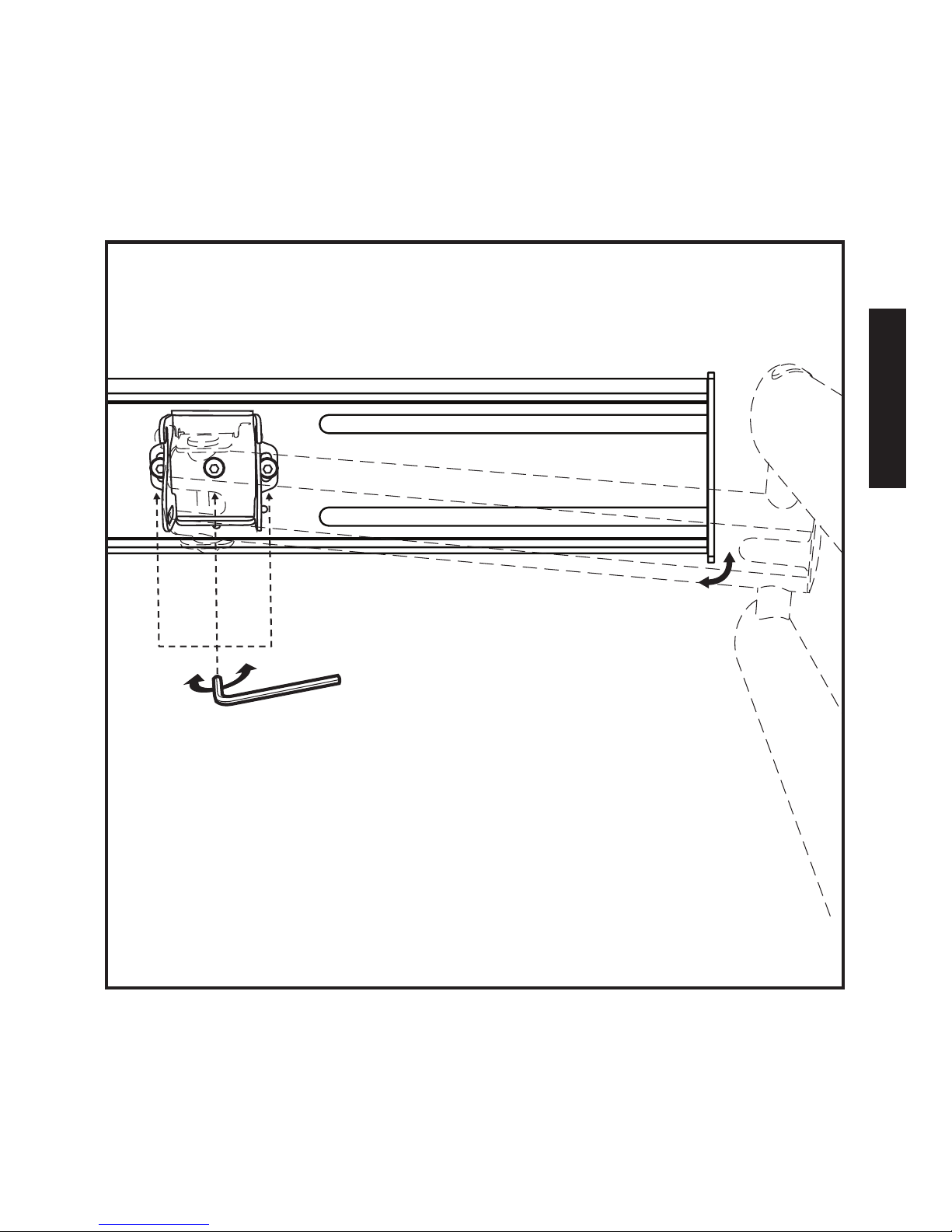
More Great Products from Monster FlatScreen
™
Get the Look You Want and the Performance You Need.
Monster FlatScreen CleanView™ Cable Manager
Conceal unruly cords and cables for a clean, sleek look.
Easy to install with paintable covers to match any décor.
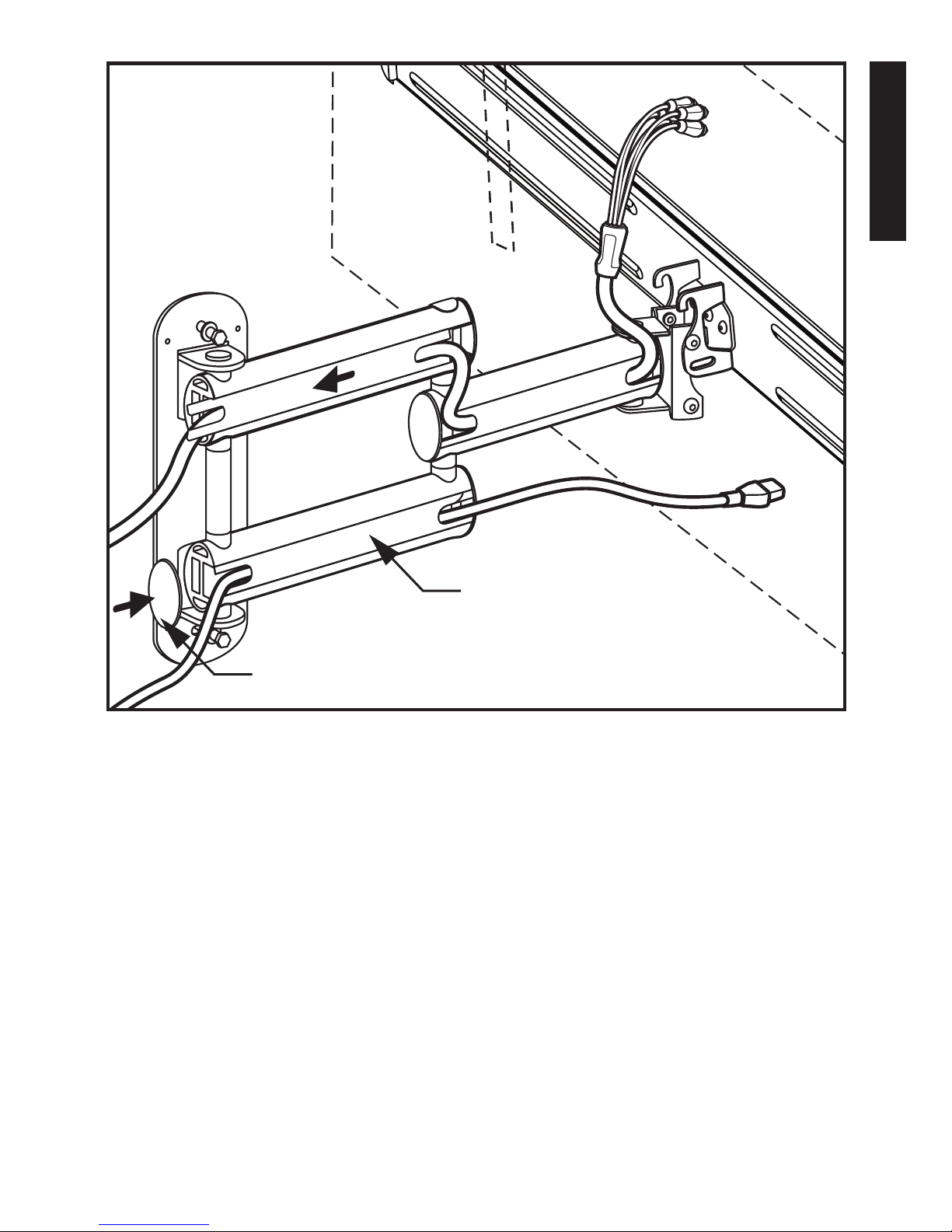
Monster FlatScreen Cables
™
Monster Flatscreen Cables are compact
and exible for easy routing and installation.
Exclusive Monster patented technologies
deliver the advanced performance you need
from your atscreen TV.
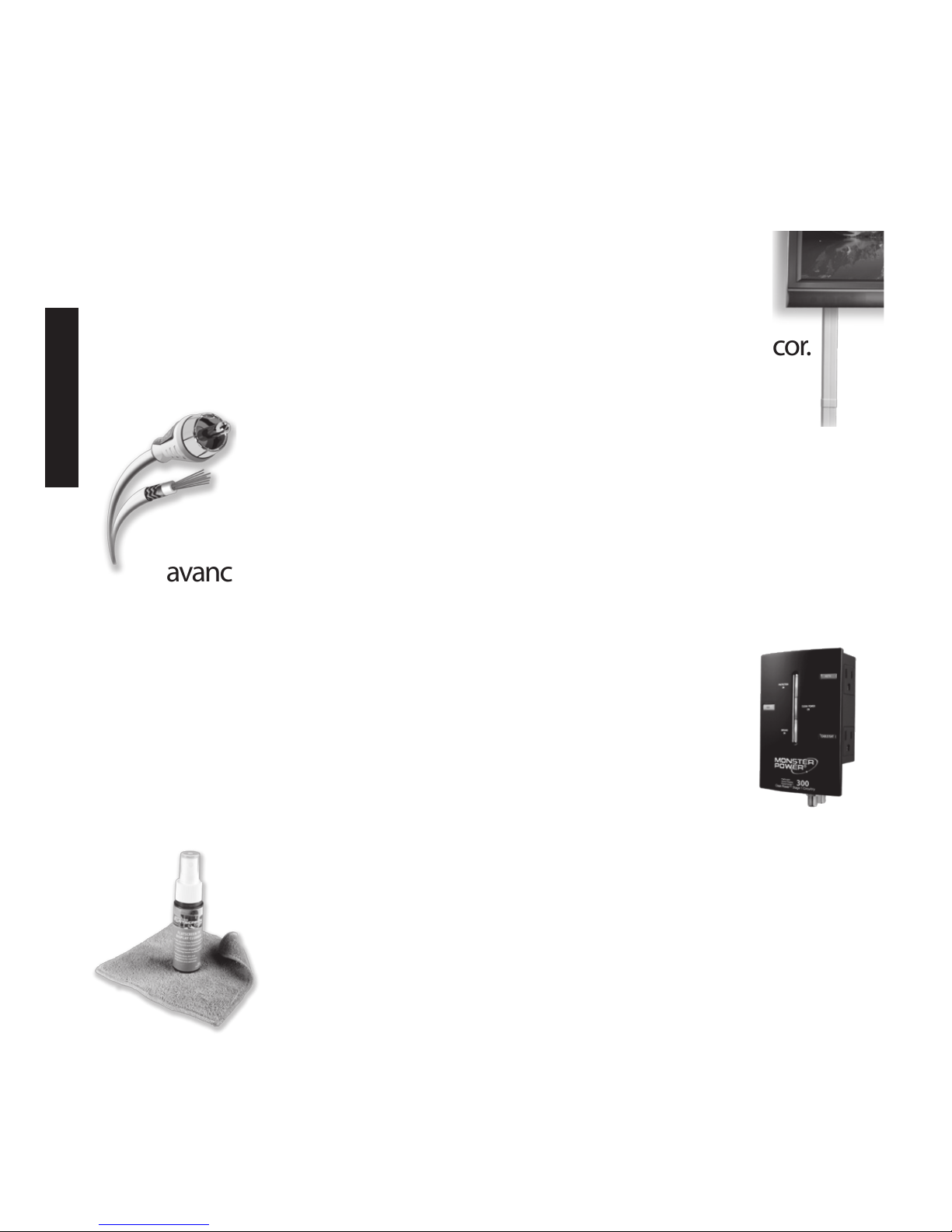
Monster FlatScreen PowerProtect™ and PowerCenters
™
Protect your atscreen TV from harmful surges
and spikes and maximize performance with
Monster Tri-Mode® surge protection and HD
Clean Power® ltering, designed specically
for HDTVs.
Monster FlatScreen Clean
™
Safely clean your LCD or plasma atscreen
TV without staining, streaking, or dripping.
Ultra-soft MicroFiber cloth won’t scratch
delicate screen coatings.
For more details on all our Monster FlatScreen products,
visit us at MonsterCable.com/FlatScreen
Page 5

ENGLISH
1
Medium Articulating FlatScreen Mount
This mount is designed to mount 27"-to-46" atscreen
televisions to vertical walls. Maximum weight capacity
is 100 lbs.
SAFETY WARNING: If you don’t understand these
directions, or have doubts about this product’s installation,
please call a qualied contractor or contact Monster Cable
Products, Inc.
U.S. and Mexico customers: call 1-877-800-8989
Canada customers: call 1-866-348-4171
Before installing, carefully review the instructions
to ensure that no parts are missing or defective. Improper
installation can cause damage or serious injury. Do not use
this product for any purpose not explicitly specied
by Monster. Monster is not liable for damage or injury
caused by incorrect assembly, incorrect mounting
or incorrect use.
All hardware is supplied for the following wall conditions:
Wood stud, brick, solid concrete, and concrete block.
Note: The supplied hardware is not for steel stud walls.
If you are uncertain about the nature of your wall
construction, consult an installation contractor.
FLATSCREEN
MOUNTS
Page 6
ENGLISH
2
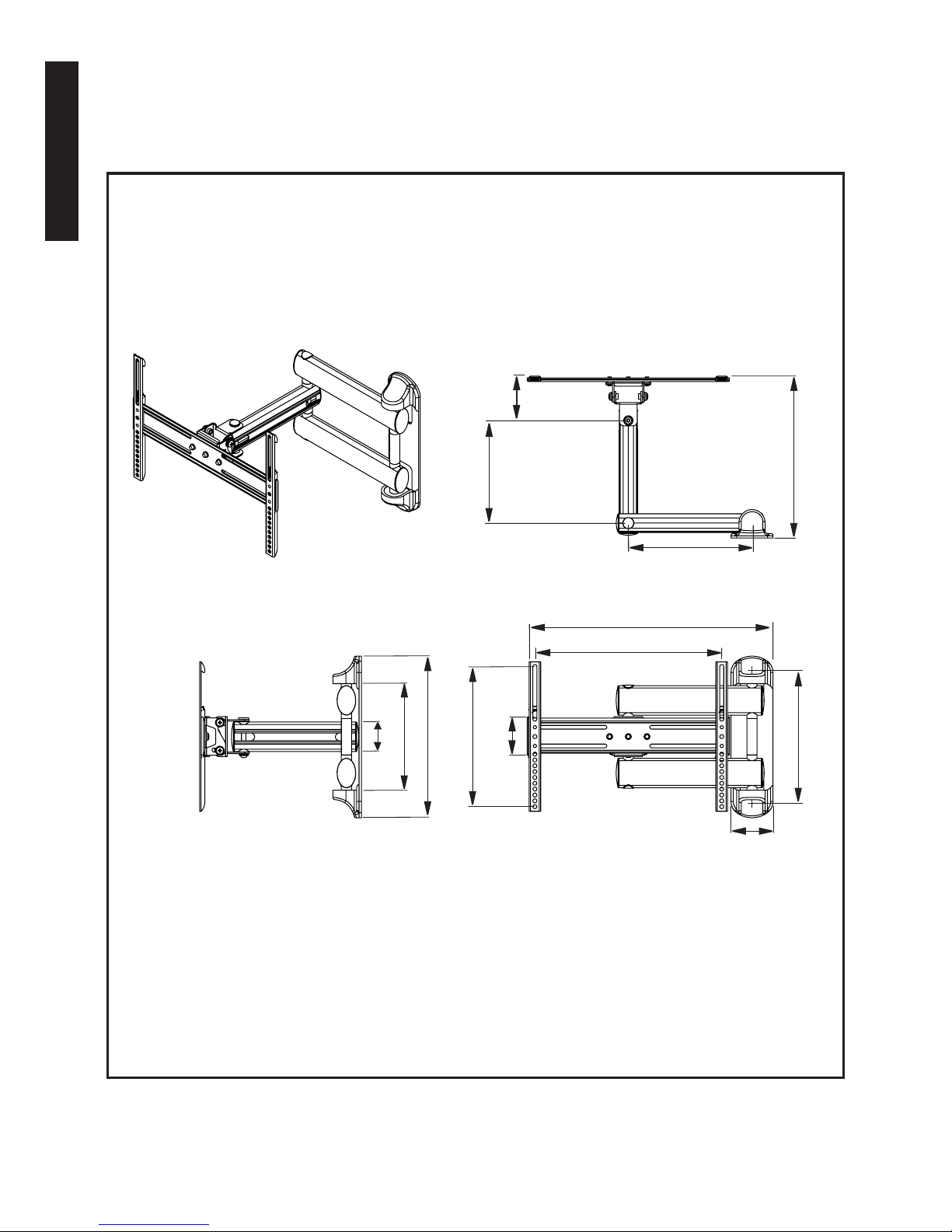
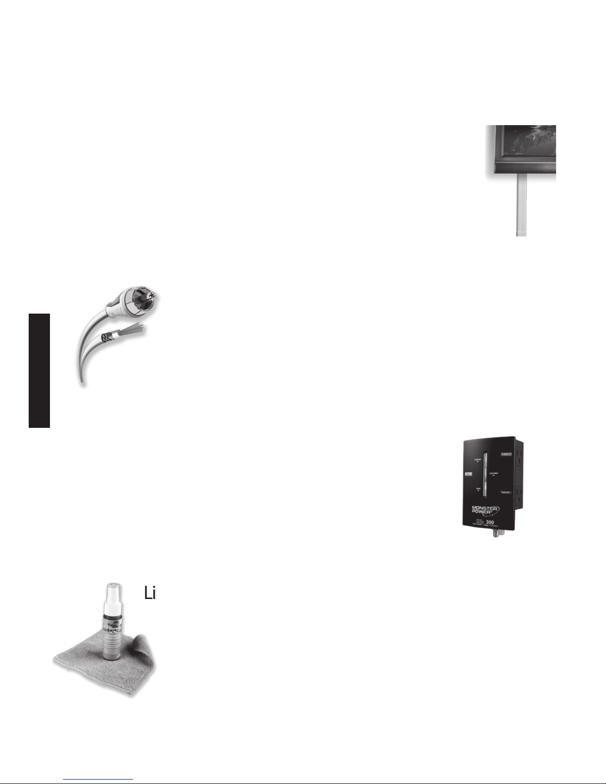
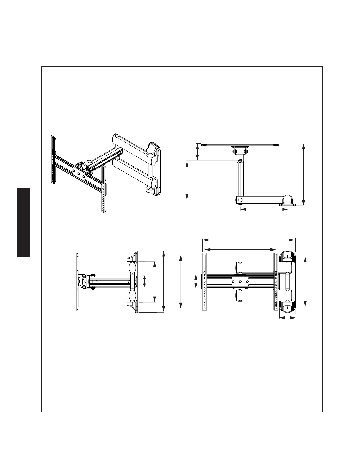
Specications and Notes:
8.7" (22cm)
3.7"
(9.5cm)
13.6" (34.6cm)
10.5" (26.6cm)
20.7" (52.6cm)
15.7" (40cm)
11.2" (28.5cm)
3.5" (9cm)
11.8" (30cm)
3"
(7.5cm)
2.5" (6.3cm)
9" (22.8cm)
13.6" (34.6cm)
Monster is constantly striving to improve its products.
Specications are subject to change without notice.
VESA™ 100x100/200x100/200x200/300x200/400x200/300x300/
400x300/400x400 Compliant
Page 7
ENGLISH
3
Required Tools
Wood Stud Mounting:
Electronic stud sensor•
Level (included)•
Electric hand drill•
3/16" drill bit•
Phillips screwdriver•
Combination wrenches or socket set•
Masonry Mounting
(brick, solid concrete, concrete blocks):
Above tools, plus hammer•
Replace 3/16" drill bit with 1/2" masonry drill bit•
Adapter Included for VESA™ 400x400 Pattern:
VESA is an international organization that
sets industry-wide standards for consumer
electronics. VESA information referred
to in this manual describes the patterns
of holes in the back of your TV and how they
match to specic Monster Flatscreen™ mounts.
Four extension adapters are included to extend
the mount’s VESA compliant standard to 400x
400mm. If your TV’s VESA pattern requires this
adapter, refer to pages 14-15 for instructions.
Page 8

ENGLISH
4
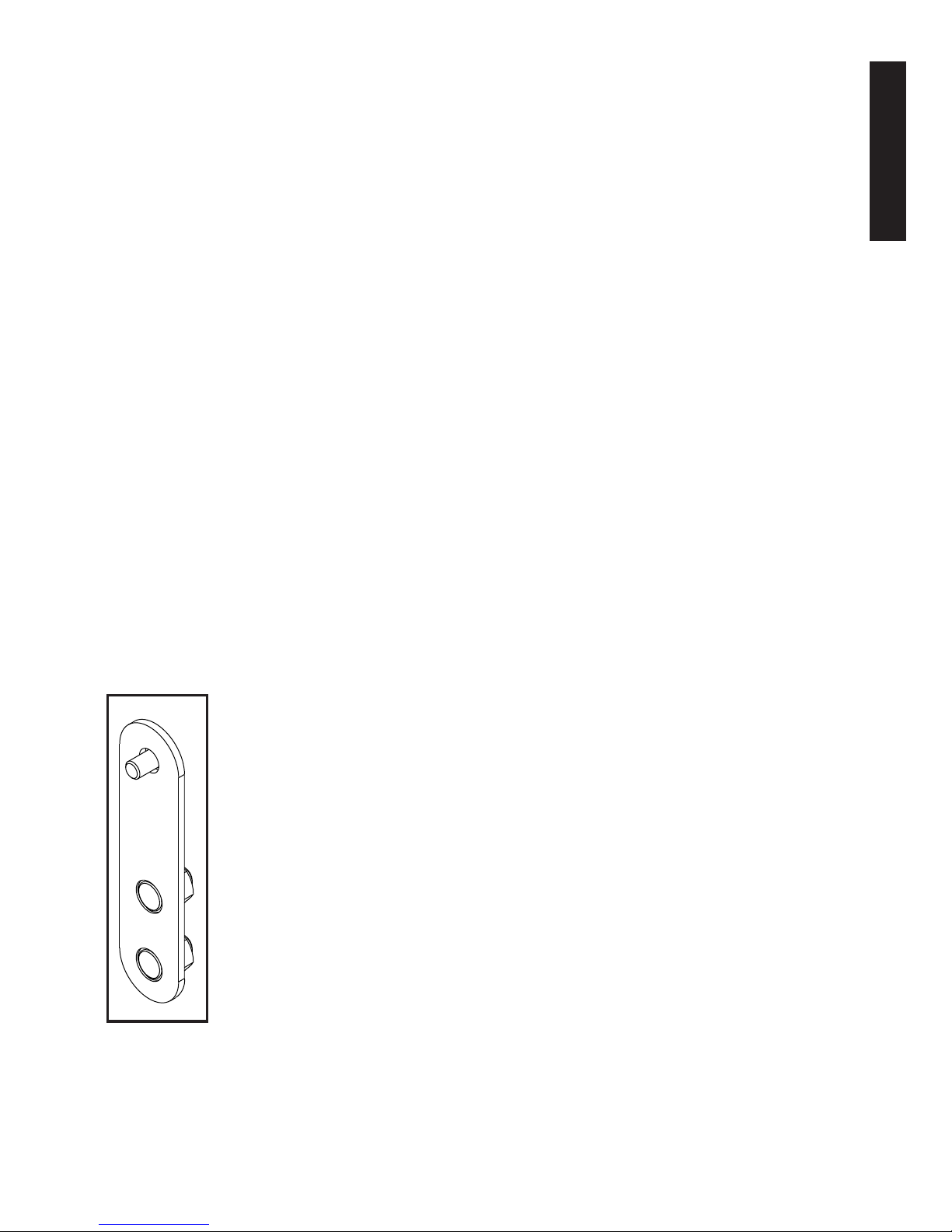
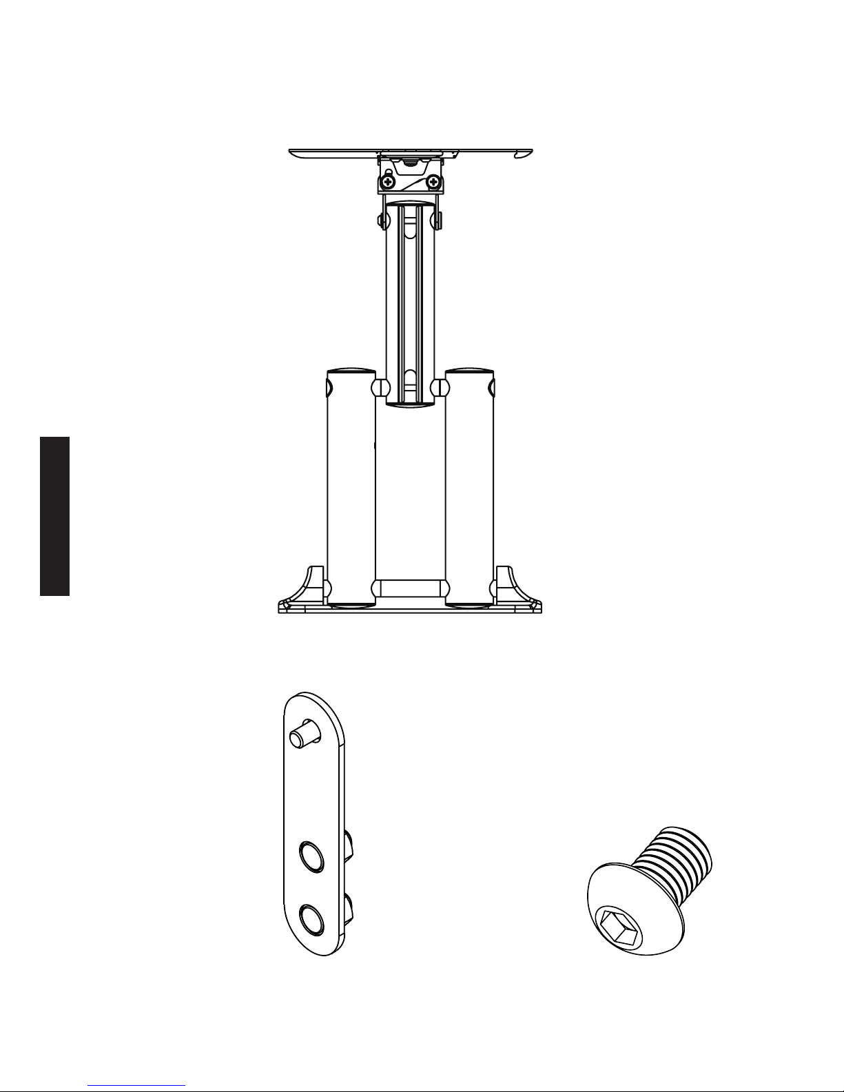
Package Contents
1 Mounting System
4 Adapters
4 Allen Head Screws
Page 9
ENGLISH
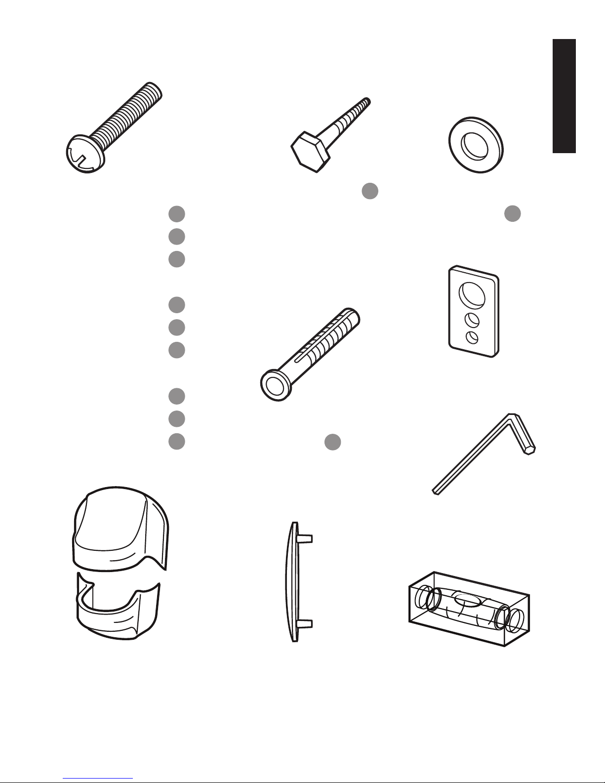
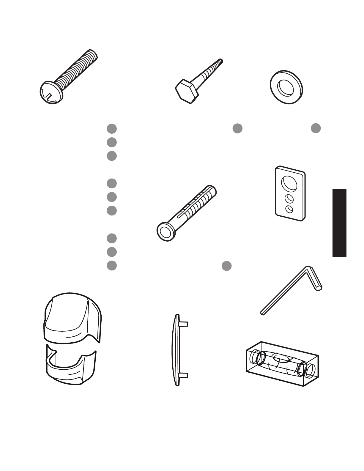
5
2 Allen
Wrenches
Phillips Screws
4 ea. M4x12 A
4 ea. M4x25 B
4 ea. M4x40 C
4 ea. M5x12 D
4 ea. M5x25 E
4 ea. M5x40 F
4 ea. M6x12 G
4 ea. M6x25 H
4 ea. M6x40 I
Bubble
Level
2 Round
Washers K
2 Lag Bolts J
2 Concrete
Anchors L
If any parts are missing, please call 800-877-8989. Parts in supplied hardware kit
are numbered as above.
2 Quick-Snap
Screw Caps
5 End Caps
4 Square Washers
Page 10

ENGLISH
6
Important: Read Before Installing
Warning:
DO NOT install on a sloping surface. Install
exclusively on a vertical surface.
DO NOT mount to cabinetry made of particleboard.
DO NOT install in a room with excessively high
temperatures or high humidity. Install at least 3 ft.
from all water sources.
DO NOT install near an air conditioner.
DO NOT install in a location where there
is excessive dust, smoke or moisture.
These sources can create a re.
DO NOT apply unnecessary stress or load
on the installed unit. Never hang on the unit.
DO NOT install the unit alone. Safe installation
requires at least two people.
DO NOT route your atscreen TV’s power cord
in wall. Check local building/electrical codes
for more information.
Page 11
ENGLISH
7
Caution:
To prevent eye fatigue, DO NOT install where there
is direct sunlight or excessive light.
When carrying out maintenance, disconnect
the TV’s power supply to avoid electrical shock.
If planning to route AV cable in wall, only use cable
UL-certied for this use.
Pre-Installation Checklist
o Your mounting location must have at least one
wall stud.
o Your view of the mounting location must be free
of glare or other obstructions.
o Your mounting location must be near an AC power
outlet. Ideally the outlet should be behind your TV.
This allows you to conceal your display’s power cord.
o Your mounting location must be at least 3 ft.
from any source of heat or water
TIP
To hide your TV’s power cord and AV cables install
a Monster FlatScreen™ CleanView™ Cable Manager.
Page 12
ENGLISH
8
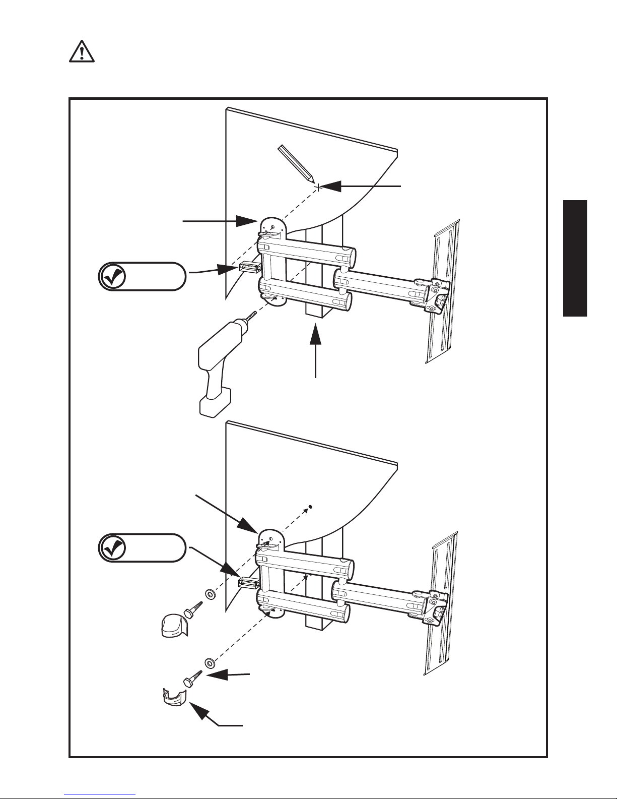
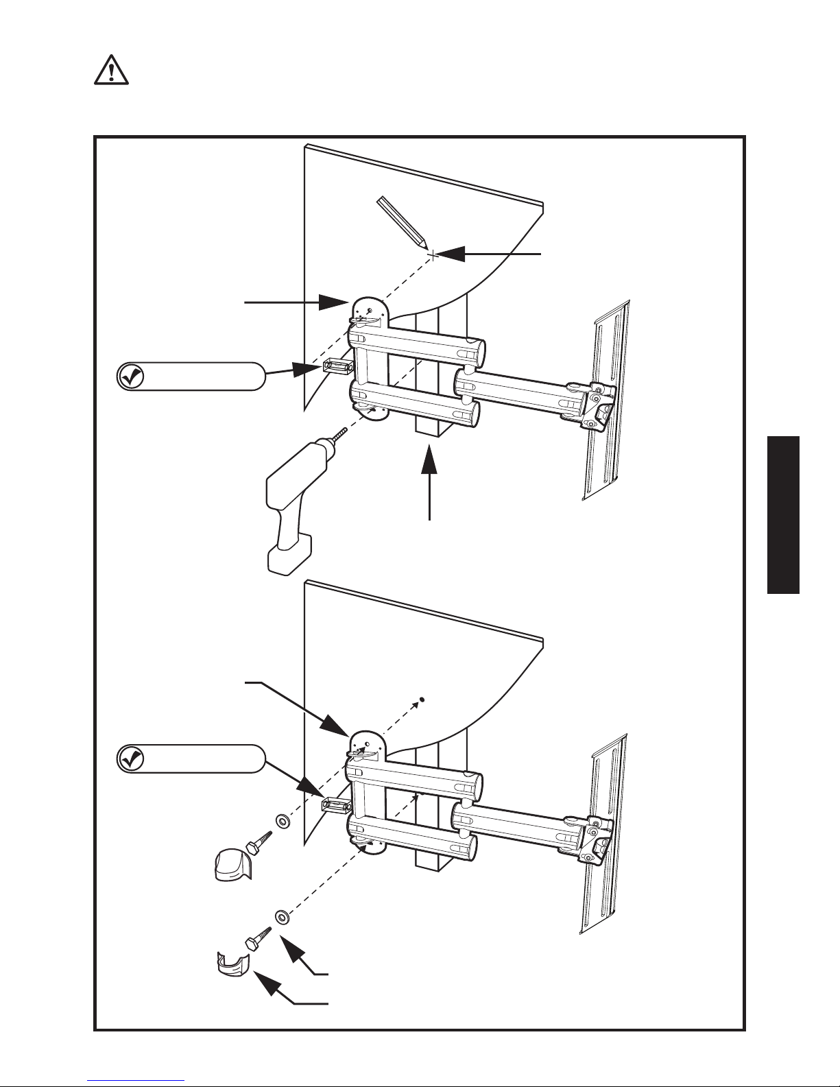
Installing the FlatScreen Mount
Choose a mounting location with convenient
access to an AC power outlet.
Wood Stud Mounting:
Using an electronic stud sensor, locate a wall stud 1)
at your desired mounting location.
LEVEL
CHECK
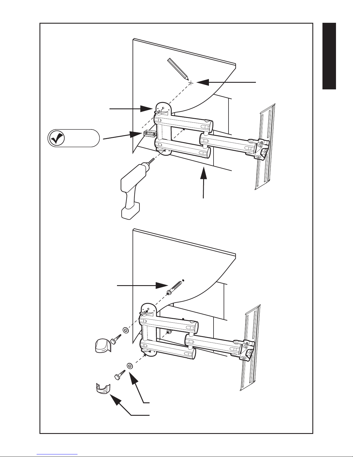
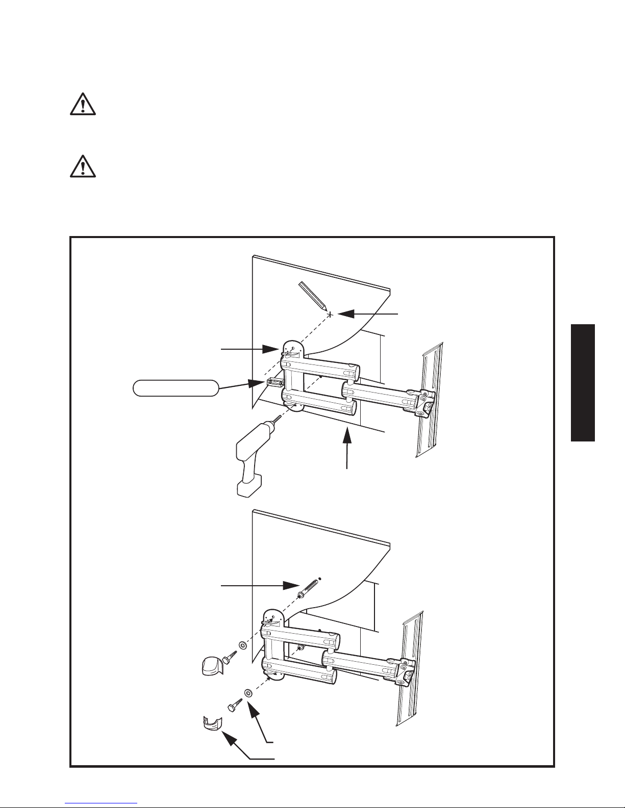
2) With the help of a friend, position the wall
plate over wall stud. Using the provided level, conrm
that the wall plate is vertically straight.
For best results, position the level horizontally with
the narrow end ush against the side of the wall plate.
Hold the plate rmly in place.
Mark the stud center in the top and bottom mounting 3)
holes with a pencil.
With your electrical drill and 3/16" bit, pre-drill a 3" 4)
deep hole at each mark.
Attach the wall plate to the wall using the supplied 5)
lag bolts and round washers, as shown to the right.
Tighten each bolt with your electric drill or socket
wrench. Turn clockwise until secure.
Attach the wall plate’s Quick-Snap Screw Caps 6)
to conceal the installed lag bolts.
DO NOT over tighten bolts. This can damage
the wall plate or the surface of your wall.
Page 13

ENGLISH
9
LEVEL
CHECK
LEVEL
CHECK
Wall
Mounting
Plate
Wall
Mounting
Plate
Wood Stud
Lag Bolts and Washers
Quick-Snap Screw Caps
3/16" Hole
(3" Deep)
Page 14

ENGLISH
10
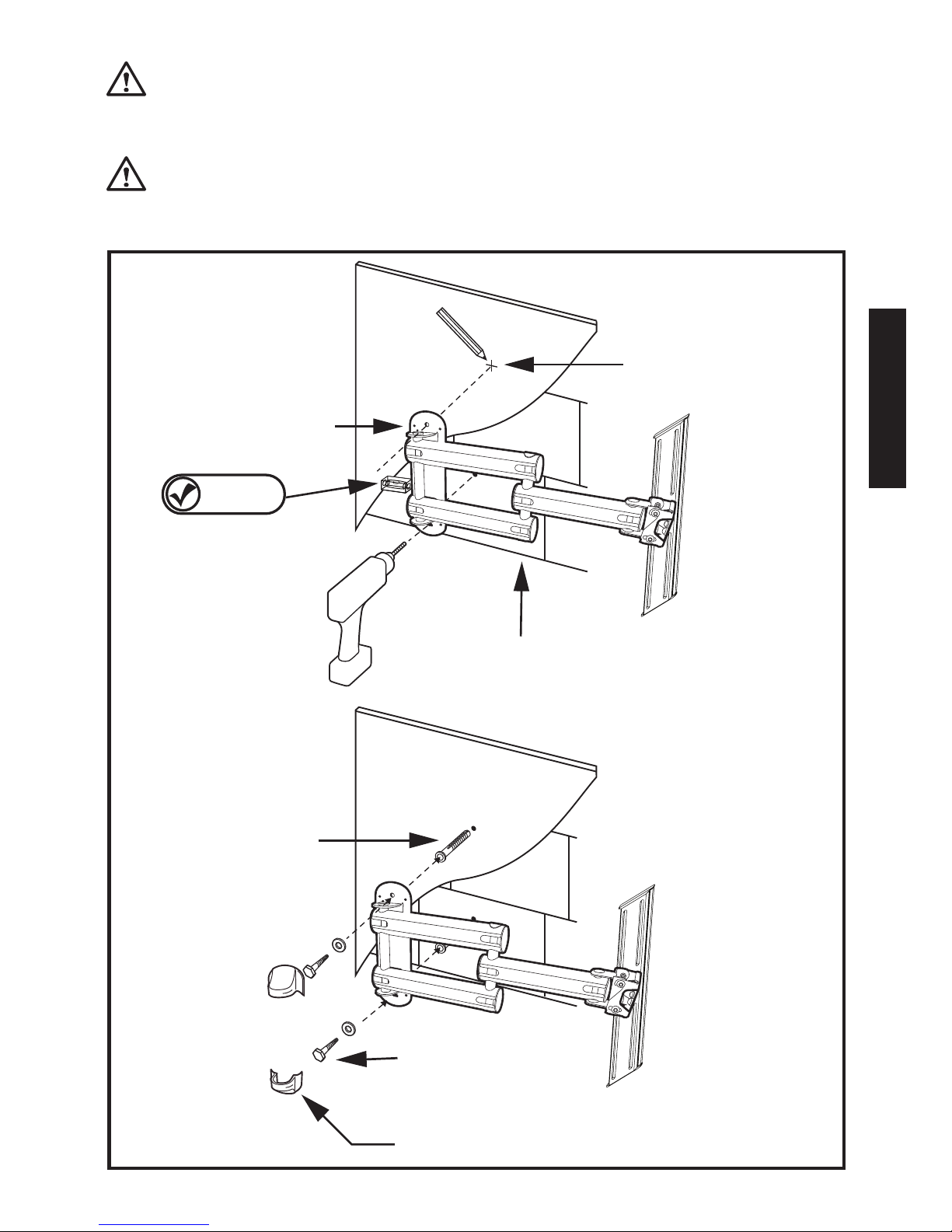
Installing the FlatScreen Mount c ontinued
Masonry Mounting
Masonry mounting requires specialized knowledge, skills
and tools. Monster highly recommends that you seek the
help of a professional installer when mounting to masonry.
With the help of a friend, position the mounting plate 1)
in your desired mounting location.
LEVEL
CHECK
2) Using the provided level, conrm that the
wall plate is vertically straight. Position the level
horizontally with the narrow end ush against the side
of the wall plate. Hold the plate rmly in place.
Mark the centers of the top and bottom mounting 3)
holes on the wall plate with a pencil. Be careful not to
mark a mortar joint. With your electrical drill and 1/2"
masonry bit, pre-drill a 3" deep hole at each mark.
Install the supplied plastic anchors in each hole. 4)
Tap into hole until fully seated.
Attach the wall plate to the wall using the supplied 5)
lag bolts and round washers, as shown to the right.
Attach the wall plate’s Quick-Snap Screw Caps 6)
to conceal the installed lag bolts.
DO NOT over tighten bolts. This can damage
the wall plate or the surface of your wall.
DO NOT release the wall plate until you
are absolutely sure it is secured to the wall.
Page 15
ENGLISH
11
LEVEL
CHECK
Masonry
Wall
Wall
Mounting
Plate
1/2" Hole
(3" Deep)
Concrete
Anchors
Lag Bolts and Washers
Quick-Snap Screw Caps
Page 16

ENGLISH
12
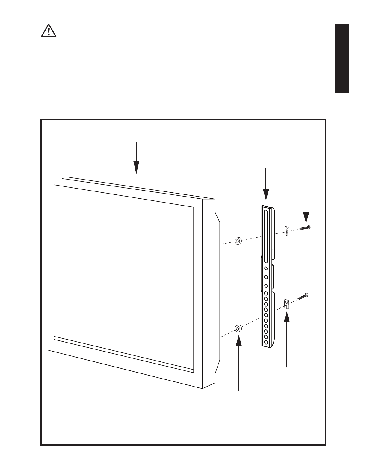
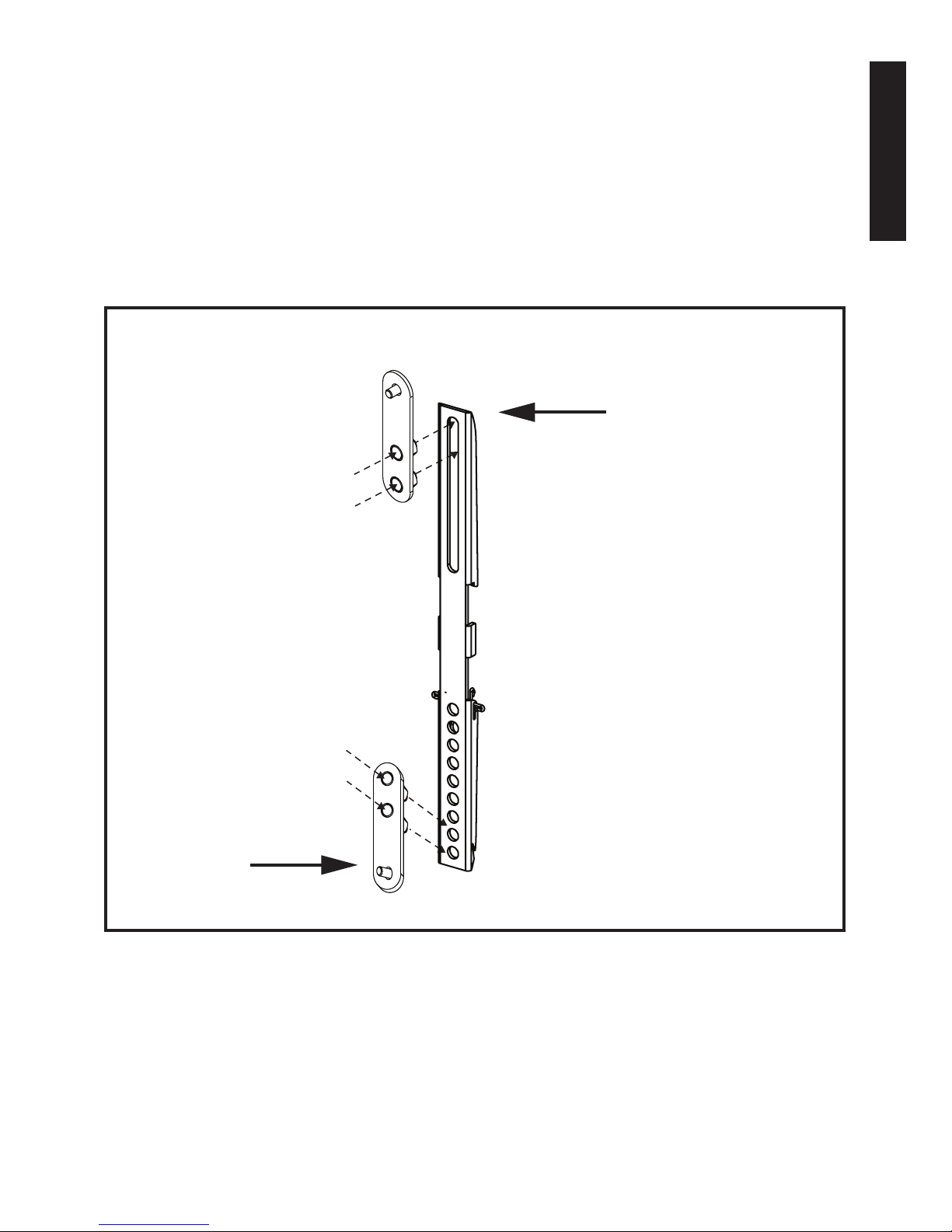
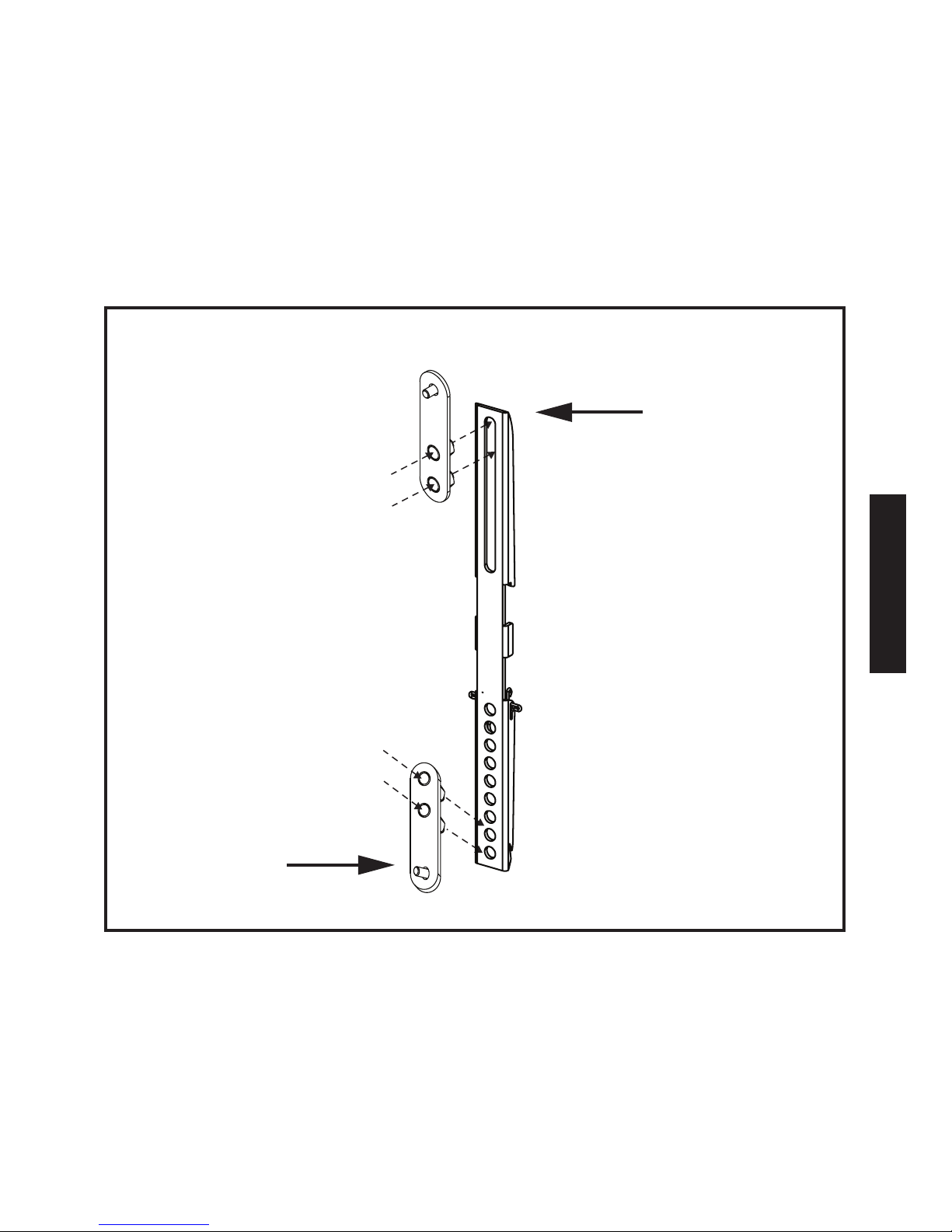
Attaching the Vertical Adjustment Bars
to the TV
DO NOT lay your TV face down when attaching
the Vertical Adjustment Bars. This can cause
permanent damage to your screen. Lean
it against a wall or other solid surface
so it remains vertically upright.
The television should be unplugged before
threading any bolt or screw into the back panel.
Your mounting system features 12 sets of screws of varying
diameter and length. Before attaching the adjustment
bars to your display, determine which screw set is correct
for your display.
TVs with at backs use a shorter screw without
a spacer. TVs with curved backs or recessed inserts
may require a longer screw with a spacer between
the TV and adjustment bars. Smaller M4, M5 or M6
screws require a square washer (supplied) between
the adjustment bar and each screw.
Locate the threaded inserts on your TV’s back panel. 1)
Thread a screw from the set into one of the inserts
to ensure it is the correct choice.
Thread screws through the adjustment bars into the 2)
TV inserts with the appropriate spacer and washer set,
if needed.
With a Phillips screwdriver, tighten the screws so the 3)
adjustment bars are rmly attached to the TV.
Page 17
ENGLISH
13
DO NOT over tighten screws. Thread screws
carefully by hand before tightening. If you feel
any resistance, remove the screw immediately.
TV
Spacer
Square
Washer
(for use)
with M4,
M5, M6
)screws)
Small
Screw
Vertical
Adjustment
Bar
Page 18

ENGLISH
14
Attaching Extension Adapters to Extend
VESA™ Pattern to 400x400
NOTE: Each adapter includes two threaded studs
and nuts. No additional hardware is required to attach
the adapter to the mount.
To attach the adapter to the ends of Vertical 1)
Adjustment Bars, place the adapter in front of the
Vertical Adjustment Bar. The adapter should be
attached at the uppermost slot at the top of each
Vertical Adjustment Bar and the lowest two holes in
the bottom of each Vertical Adjustment Bar.
Using a ½" (13mm) wrench, attach the adapter 2)
by tightening the two nuts through the back
of the Vertical Adjustment Bar.
Using a Phillips head screwdriver, ax the adapter’s 3)
head cap screws to the back of your TV
Page 19
ENGLISH
15
Vertical
Adjustment Bar
Adapter
Page 20

ENGLISH
16
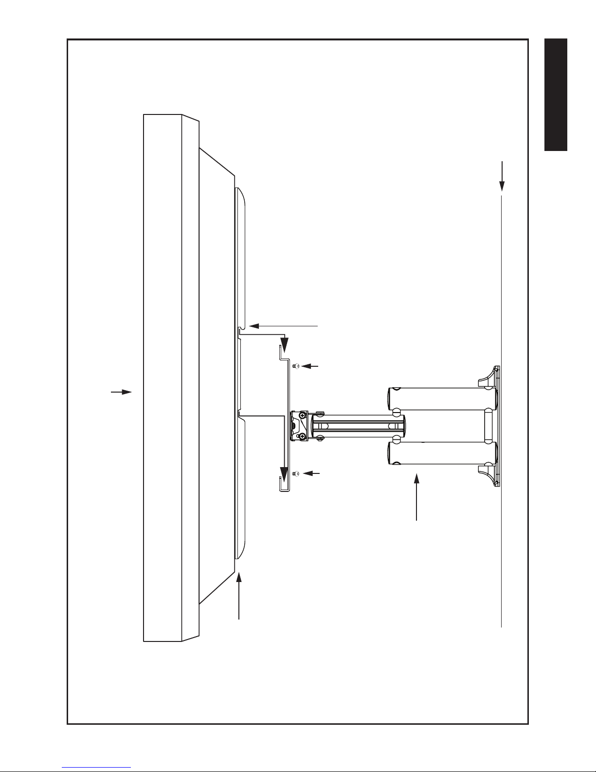
Hanging the TV and Vertical Adjustment
Bars on the Wall Plate
Monster strongly recommends that a minimum
of two people perform the following steps.
DO NOT release the TV until you are certain
it is properly mounted and secured to the
wall plate.
With the mount securely attached to the wall, extend 1)
the Z-Fold™ swing arms away from the wall.
Locate the 2) QuickLift™ hooks on the back of the Vertical
Adjustment Bars, now attached to your TV.
Hang the 3) QuickLift hooks on the TV mounting plate’s
top and bottom horizontal channels.
Secure the Vertical Adjustment Bars to the mounting 4)
plate by threading the four Allen head screws
through the back of the mounting plate
and through the vertical adjustment bars.
Tighten screws with supplied Allen wrench.
Page 21
ENGLISH
17
TV
QuickLift
Hooks
Vertical
Adjustment Bars
Wall
Mounting
System
Allen Head Screws
Allen
Head
Screws
Page 22

ENGLISH
18
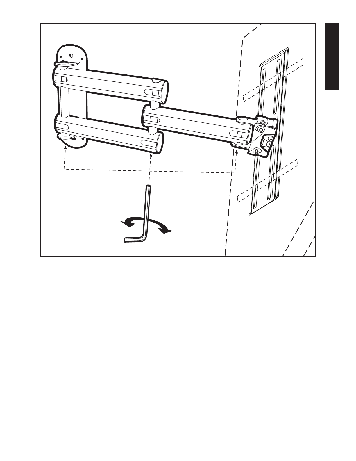
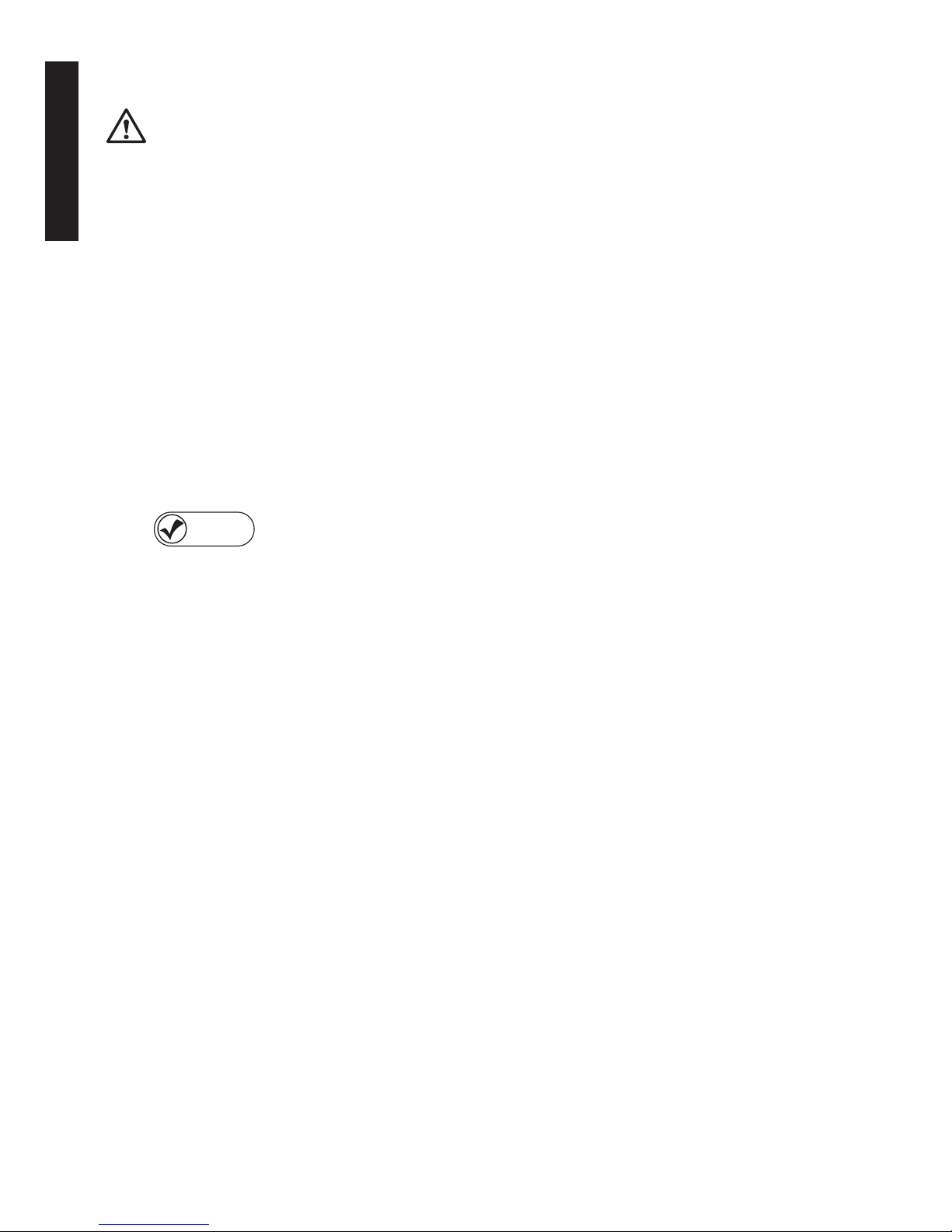
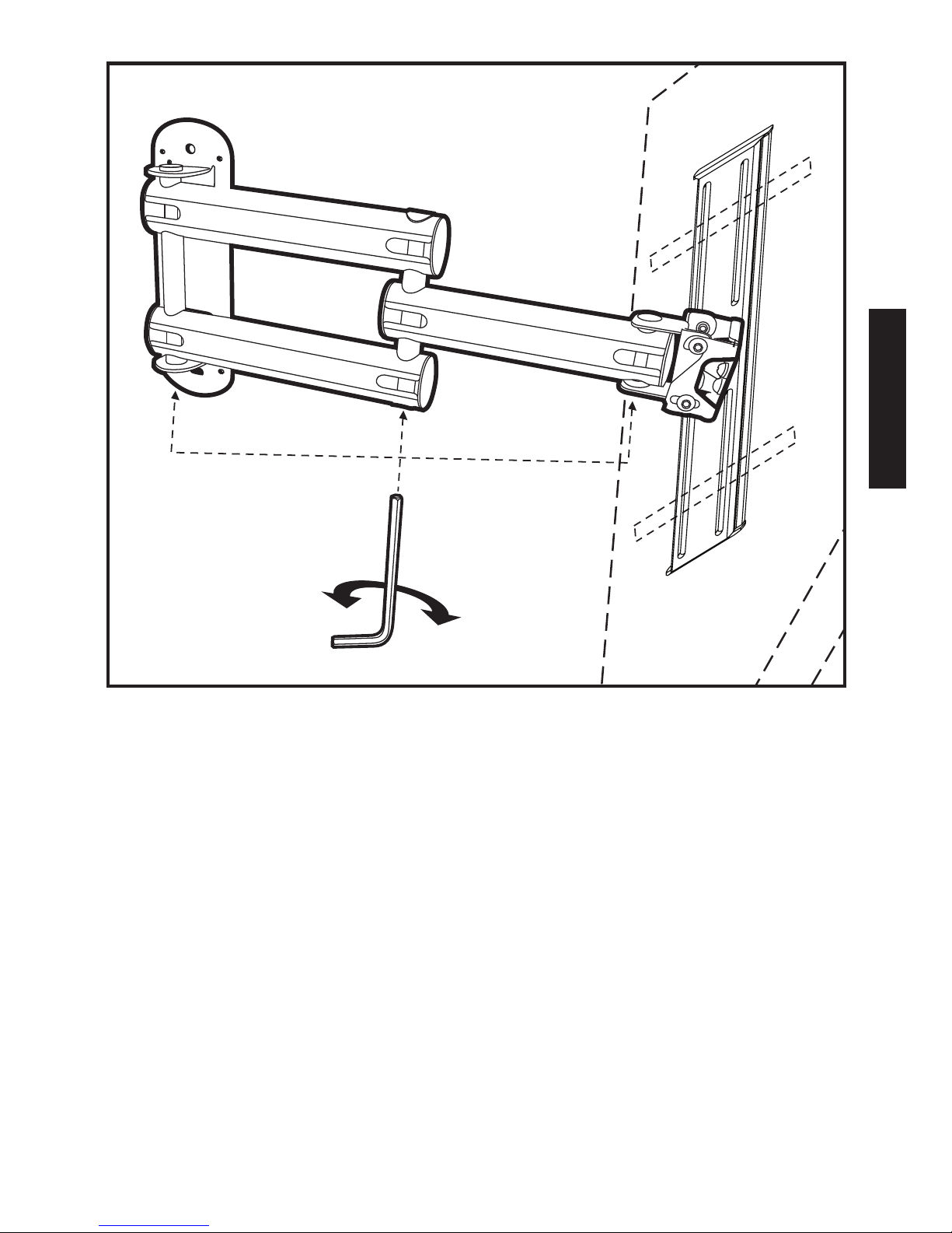
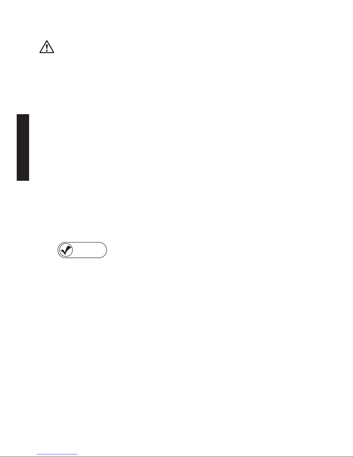
Adjusting the Flexibility of the Z‑Fold™
Extending Swing Arms
This mount features heavy-duty Z-Fold Extending Swing
Arms with three independent arm hinges.
The • Z-Fold swing arms extend your display
up to 24” from the wall.
All three arm hinges swivel your TV left or right 180.°*•
Each arm hinge has an adjustable tension screw, adjustable
before or after the TV and mounting plate are attached
to the swing arms.
Remove the plastic cap on the bottom 1)
of any arm hinge, as shown to the right,
to access its tension screw.
With an Allen wrench, turn the tension screws 2)
counterclockwise to reduce swivel tension.
Turn the screws clockwise to increase swivel tension.3)
* Actual swivel angle depends on the dimensions of TV.
Page 23
ENGLISH
19
Page 24

ENGLISH
20
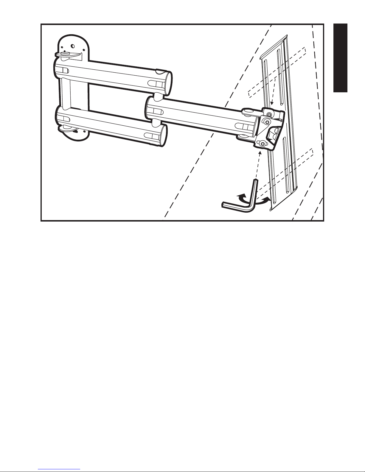
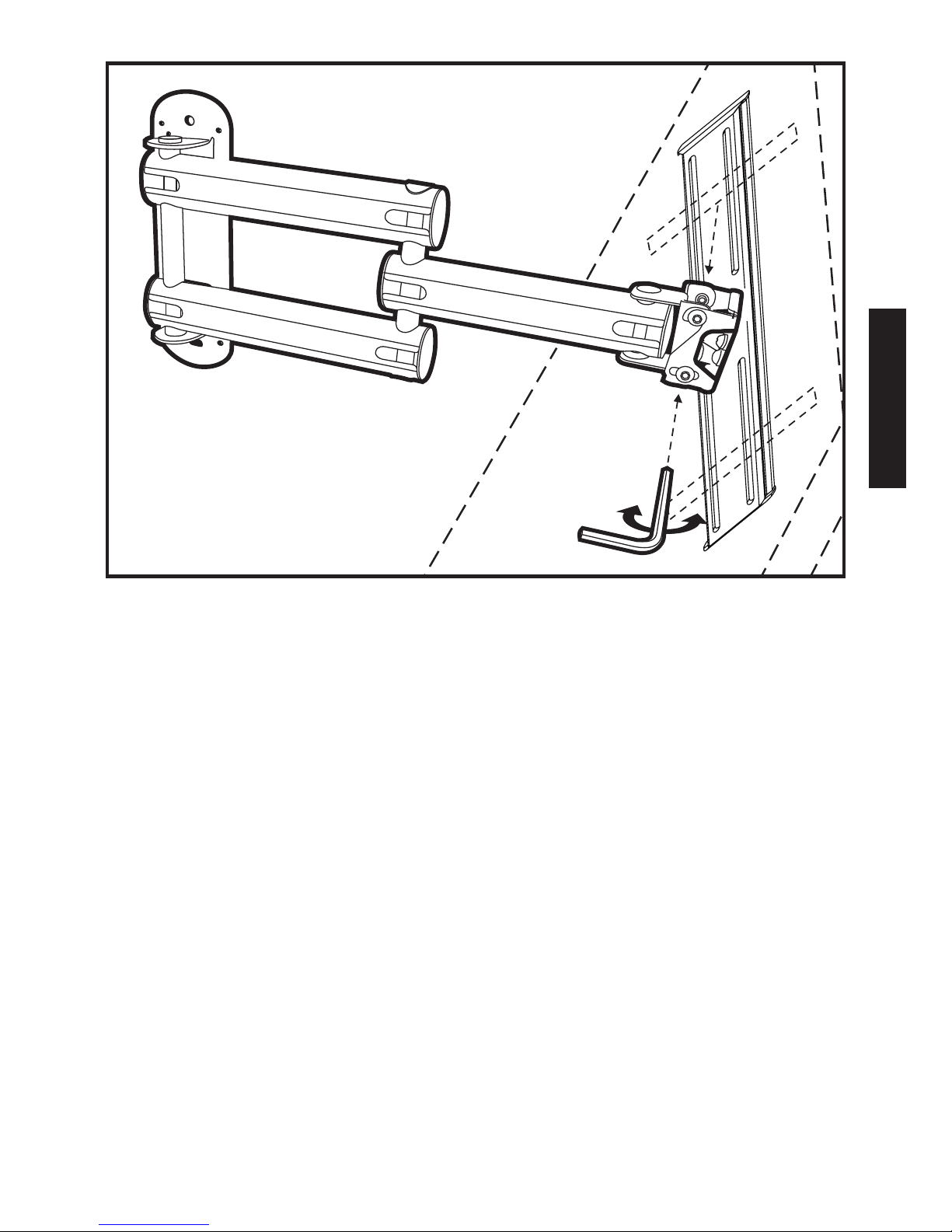
Using the Mount’s FlexTilt™
Screen Adjustment System
This mount features a FlexTilt™ screen adjustment system
for tilting the top of your TV forward 20° or backward 5.°
This reduces glare and enhances your view while seated.
Follow the steps below to quickly and easily tilt you screen.
Fully extend the mount’s 1) Z-Fold swing arms.
Note the lower tension screws on each side 2)
of the bracket connecting the Z-Fold swing arms
to the TV mounting plate.
With an Allen wrench, turn the tension screws 3)
counterclockwise to loosen the bracket and tilt
the top of the screen forward or backward.
To lock your display in place at the desired tilt, 4)
retighten the tension screws, turning them clockwise.
Page 25
ENGLISH
21
Page 26
ENGLISH
22
Leveling the TV
DO NOT over-loosen the tension screws on
the back of the TV mounting plate. The mounting
plate and TV could fall o the mount.
Note the three tension screws on the back 1)
of the TV mounting plate as shown.
Turn the left and right tension screws counterclockwise 2)
to initiate screen leveling.
If rotation is still limited after loosening the left 3)
and right screws, loosen the center tension screw.
LEVEL
CHECK
4) By hand, rotate the screen left or right.
In the desired position, use the supplied level
to ensure the screen is completely horizontal.
Retighten the tension screws, turning them clockwise.
Page 27
ENGLISH
23
Page 28

ENGLISH
24
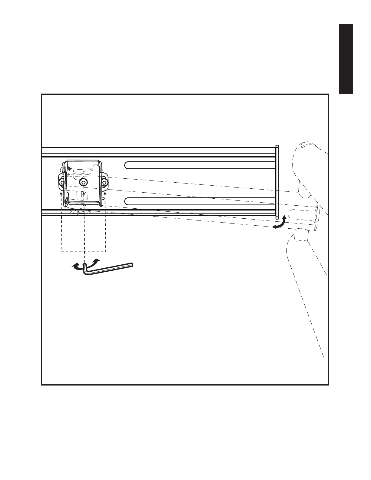
Routing Your TV’s Power Cord and AV Cable
through the Cable Management System
With the mount completely installed on the wall 1)
and your TV properly secured to the mount,
fully extend the mount’s Z-Fold™ swing arms.
Swing the mount completely to the left or right. 2)
This enables you to slide o the cable channel covers
on all three swing arms.
Connect your TV’s power cord to the TV (if TV uses 3)
a detachable-type power cord).
Slide the cable channel covers o the swing arms, 4)
as shown to the right.
Route your TV’s power cord through the bottom 5)
cable channel.
Route AV cable from your wall, set-top box, AV receiver, 6)
or other source through the top channel and second
arm, as shown to the right and make connections to
your TV.
Slide the cable channel covers back into place. 7)
Snap the swing arm end caps back on, as shown.
Page 29
ENGLISH
25
Congratulations
You’ve successfully installed your Monster FlatScreen™
Articulating Mount.
Visit www.MonsterCable.com/FlatScreen for more
innovative Monster FlatScreen products.
Cable channel
covers
End caps (5)
Page 30

ENGLISH
26
LIMITED WARRANTY FOR CONSUMERS
Monster, LLC., 7251 West Lake Mead Blvd., Las Vegas, NV 89128, USA, (415) 840-2000
(“Monster”) extends You this Limited Warranty. Statutory or common law may
provide You with additional rights or remedies, which shall not be aected
by this Limited Warranty.
DEFINITIONS
“Adequate Use” means use of the Product (i) within a home or dwelling, (ii) for private
(as opposed to commercial) purposes, (iii) in conformance with all applicable local,
state or federal law, code or regulations (including without limitation building
and/or electrical codes), (iv) in accordance with manufacturer recommendations
and/or instructions in the materials and documentation that accompany the Product,
and (v) if applicable, with proper electrical grounding.
“Authorized Dealer” means any distributor, reseller or retailer that (i) was duly
authorized to do business in the jurisdiction where it sold the Product to You,
(ii) was permitted to sell You the Product under the laws of the jurisdiction where
You bought the Product, and (iii) sold You the Product new and in its original packaging.
“Formal Warranty Claim” means a claim made in accordance with the section
“Formal Warranty Claims” herein.
“Product” means a Product (i) that is listed in the Specications Table below,
(ii) that You bought from an Authorized Dealer new and in its original packaging,
and (iii) whose serial number, if any, has not been removed, altered, or defaced.
“Product Defect” means an inadequacy of the Product that existed at the time when
You received the Product from an Authorized Dealer and that causes a failure of the
Product to perform in accordance with Monster’s documentation accompanying the
Product, unless such failure has been caused completely or partly by (a) any use other
than Adequate Use, (b) transportation, neglect, misuse or abuse by anyone other
than Monster’s employees; (c) alteration, tampering or modication of the product by
anyone other than a Monster employee; (d) accident (other than a malfunction that
would otherwise qualify as a Product Defect); (e) maintenance or service of the Product
by anyone other than a Monster employee; (f) exposure of the Product to heat, bright
light, sun, liquids, sand or other contaminants; or (g) acts outside the control of Monster,
including without limitation acts of God, re, storms, earthquake or ood.
“Warranty Period” means the time period during which Monster must have received
Your Formal Warranty Claim. The dierent Warranty Periods related to Product Defects
are dened in the Specications Table below. The Warranty Period commences on the
date when You purchased or received (whichever occurs later) the Product from
an Authorized Dealer as evidenced by the Authorized Dealer’s invoice, sales receipt
or packing slip. If You do not have written proof of the date of purchase or receipt,
Page 31

ENGLISH
27
then the Warranty Period commences three (3) months after the date when the Product
left Monster’s or its factory as evidenced by Monster’s records. The Warranty Period
ends after the time dened in the Specications Table has expired or after You have
transferred ownership of the Product, whichever occurs earlier. Also, You must call
Monster and obtain a Return Authorization Number (as described under “How to Make
a Claim”) within two (2) months after You discover a Product Defect (or should have
discovered it, if such Product Defect was obvious).
“ Yo u ” means the rst individual person that purchased the Product in its original
packaging from an Authorized Dealer. This Limited Warranty does not apply to persons
or entities that bought the Product (i) in used or unpackaged form, (ii) for resale, lease
or other commercial use, or (iii) from someone other than an Authorized Dealer.
SCOPE OF THIS LIMITED WARRANTY
PRODUCTS. If a Product contained a Product Defect when You bought it from an
Authorized Dealer and Monster receives a Formal Warranty Claim from You within two
(2) months after You discover such Product Defect (or should have discovered it, if such
Product Defect was obvious) and before the end of the Warranty Period for Product
Defects applicable to the aected Product, then Monster will provide You with one of
the following remedies: Monster will (1) repair or, at Monster’s sole discretion, replace
the Product, or (2) refund to You the purchase price You paid to the Authorized Dealer
for the aected Product if repair or replacement is not commercially practicable or
cannot be timely made. NOTE: MONSTER DOES NOT ASSUME ANY LIABILITY FOR
ANY INCIDENTAL, CONSEQUENTIAL OR INDIRECT DAMAGES UNDER THIS LIMITED
WARRANTY.
GENERAL PROVISIONS
CHOICE OF LAW/JURISDICTION. This Limited Warranty and any disputes arising out
of or in connection with this Limited Warranty (“Disputes”) shall be governed by the
laws of the State of California, USA, excluding conicts of law principles and excluding
the Convention for the International Sale of Goods. The courts located in the State of
California, USA shall have exclusive jurisdiction over any Disputes.
OTHER RIGHTS. THIS LIMITED WARRANTY GIVES YOU SPECIFIC LEGAL RIGHTS,
AND YOU MAY ALSO HAVE OTHER RIGHTS, WHICH VARY FROM STATE TO STATE
AND JURISDICTION TO JURISDICTION, AND WHICH SHALL NOT BE AFFECTED BY
THIS LIMITED WARRANTY. THIS WARRANTY EXTENDS ONLY TO YOU AND CANNOT
BE TRANSFERRED OR ASSIGNED. If any provision of this Limited Warranty is unlawful,
void or unenforceable, that provision shall be deemed severable and shall not aect
any remaining provisions. In case of any inconsistency between the English and other
versions of this Limited Warranty, the English version shall prevail.
REGISTRATION. Please register Your Product at www.MonsterCable.com.
Failure to register will not diminish Your warranty rights.
Page 32

ENGLISH
28
SPECIFICATIONS TABLE
Product Model Warranty Period for Product
Medium Articulating Mount Lifetime
”Lifetime” means the lifetime of the original individual purchaser of the Product, or for
as long as the original individual purchaser owns the Product, whichever is less in time.
FORMAL WARRANTY CLAIM
HOW TO MAKE A CLAIM. In the event damage has occurred to Products, You must
follow these instructions: (1) Call Monster within two (2) months after You discover
a Product Defect (or should have discovered it, if such Product Defect was obvious);
(2) Give a detailed explanation of how the damage occurred; (3) Obtain a Return
Authorization Number; (4) Return the Products, shipping prepaid by You (to be
refunded if You are entitled to a remedy under the Scope of this Limited Warranty),
to Monster for verication of damage, along with a copy of Your original sales receipts
and proof of purchase (UPC label or packing slip) for such Products, the completed
claim form, and printed Return Authorization Number on the outside of the return
package (the claim form will include instructions for return).
TELEPHONE NUMBERS. If you bought the product in the United States, Latin
America, or Asia Pacic, contact Monster, LLC (455 Valley Drive, Brisbane, CA 94005)
at 1 877 800-8989. If you bought the product anywhere else, contact Monster
Technology International Ltd., Ballymaley Business Park, Ennis, Co. Clare, Ireland.
You can write or use one of the following telephone numbers: Canada 866-348-4171,
Ireland 353 65 68 69 354, Belgium 0800-79201,Czech Republic 800-142471, Denmark
8088-2128, Finland 800-112768, France 0800-918201, Germany 0800-1819388, Greece
00800-353-12008, Italy 800-871-479, Netherlands 0800-0228919, Norway 800-10906,
Russia 810-800-20051353, Spain 900-982-909, Sweden 020-792650, United Kingdom
0800-0569520
FURTHER PROCEEDINGS. Monster will determine whether a Product Defect existed.
Monster may, at its discretion, direct You to obtain a repair estimate at a service center.
If a repair estimate is required, You will be instructed on how to properly submit
the estimate and the resulting invoice to Monster for payment. Any fees for repairs
may be negotiated by Monster.
TIMING. If You bring a Formal Warranty Claim and fully comply with all terms
and conditions of this Limited Warranty, Monster will use its best eorts to provide
You with a remedy within thirty (30) days after receipt of Your Formal Warranty Claim
(if You reside in the United States - forty-ve (45) days if You reside elsewhere), unless
obstacles outside Monster’s control delay the process.
Ver.072109 – GLOBAL ©2003–2009 Monster, LLC
Page 33

29
Page 34

FRANÇAIS
30
Page 35

FRANÇAIS
31
NOTE DE LA DIRECTION DE MONSTER
MERCI de vous être procuré le support
de montage articulé Monster FlatscreenMC.
Ce support de montage reète notre
passion de créer les solutions AV les
plus novatrices et pratiques sur le marché
an d’améliorer votre expérience de
visionnement. Les supports de montage
articulé de Monster pour téléviseurs à
écran plat sont sûrs, sécuritaires et faciles
à installer. Les bras pivotants extensibles
et l’articulation multi-directionnelle orent d’innombrables
possibilités de visionnement. Commencez à proter de votre
téléviseur à votre façon — quand, où et comment vous désirez
le regarder.
Noel Lee,
Le Monster en chef
Page 36
FRANÇAIS
Voici d’autres produits de qualité signés
Monster FlatScreen
MC
Obtenez l’apparence et les performances à votre goût.
Système de gestion de câbles Monster FlatScreen
CleanView
MC
Retirez de la vue les affreux câbles et cordons d’alimentation
et obtenez un résultat d’apparence nette. Facile à installer.
Doté de couvercles à peindre pour s’harmoniser avec tout décor.
Monster FlatScreen Cables
MC
Les câbles de la collection Monster Flatscreen
Cables
MC
sont compacts et flexibles pour faciliter
leurs acheminement et installation. Les technologies
exclusives brevetées de Monster offrent les performances
avancées que vous recherchez dans un téléviseur à écran plat.
Monster FlatScreen PowerProtectMC et PowerCenters
MC
Protégez votre téléviseur à écran plat contre les
surtensions et les crêtes de tension nuisibles et
maximisez ses performances à l’aide du parasurtenseur
Monster Tri-Mode
MD
et le filtre HD Clean Power,
MD
spéciquement conçus pour les téléviseurs HD.
Monster FlatScreen Clean
MC
Nettoyez en toute sécurité votre téléviseur à écran ACL
ou au plasma sans risque de laisser des rayures, des
taches ou des égouttements. Le chion MicroFiber
ultradoux n’égratigne pas l’enduit délicat des écrans.
Pour plus de details sur tous nos produits de la collection
Monster FlatScreen, visitez-nous à l’adresse
MonsterCable.com/FlatScreen
Page 37

FRANÇAIS
33
Support de montage articulé, format moyen
Conçu pour supporter des téléviseurs à écran plat de
27 po à 46 po sur un mur vertical. Poids maximal : 100 lbs.
CONSIGNES DE SÉCURITÉ : Si vous ne comprenez pas ces
directives ou si vous avez des doutes quant à l’installation
de ce produit, veuillez appeler un technicien qualié ou
Monster Cable Products, Inc.
Clients des É.U. et du Mexique : appelez au
1-877-800-8989
Clients du Canada : appelez au 1-866-348-4171
Avant de procéder à l’installation, lisez attentivement
les instructions pour vous assurer qu’aucune pièce n’est
manquante ou défectueuse. Une mauvaise installation
peut provoquer des dommages et des blessures
graves. N’utilisez en aucun cas ce produit à des ns non
explicitement spéciées par Monster ou le fabricant.
Ni Monster ni le fabricant ne sauraient être tenus
responsables de tout dommage ou de toute blessure
provoqué(e) par un mauvais montage ou une
mauvaise utilisation.
Toutes les ferrures sont fournies pour les types de murs
suivants : montants en bois, briques, béton massif
et blocs de béton.
Remarque : Les ferrures fournies ne conviennent pas
aux murs avec montants en acier. Si vous ne connaissez
pas le type de construction de votre mur, consultez un
entrepreneur d’installation.
Page 38

FRANÇAIS
34
Spécications et remarques :
8.7" (22cm)
3.7"
(9.5cm)
13.6" (34.6cm)
10.5" (26.6cm)
20.7" (52.6cm)
15.7" (40cm)
11.2" (28.5cm)
3.5" (9cm)
11.8" (30cm)
3"
(7.5cm)
2.5" (6.3cm)
9" (22.8cm)
13.6" (34.6cm)
Monster s’eorce continuellement d’améliorer ses produits.
Les spécications peuvent donc être modiées sans préavis.
VESA™ 100x100/200x100/200x200/300x200/400x200/300x300/
400x300/400x400 Conforme
Page 39

FRANÇAIS
35
Outils requis
Montage sur un mur à montants :
Détecteur de montant électronique•
Niveau (inclus)•
Perceuse électrique à main•
Foret de 3/16 po•
Tournevis cruciforme•
Jeu de clés de serrage•
Montage sur un mur de maçonnerie
(brique, béton massif, blocs de béton) :
Les outils énumérés ci-dessus, plus un marteau•
Remplacez le foret de 3/16 po par une mèche •
de maçonnerie de ½ po
Adaptateur inclus pour le modèle VESA™
à motif 400 x 400 :
VESA est un organisme international qui établit les
normes de l’industrie pour ce qui est des appareils
électroniques. L’information VESA contenue dans
ce manuel décrit les modèles de trous pour l’arrière
de votre téléviseur et leur agencement avec les
supports de montage Monster Flatscreen™.
Quatre adaptateurs de rallonge sont inclus an
de pouvoir allonger le support de montage
conforme aux normes VESA jusqu’à 400 x 400 mm.
Si le modèle VESA de votre téléviseur nécessite
cet adaptateur, consultez les pages 46 et 47 pour
obtenir les instructions.
Page 40

FRANÇAIS
36
Contenu de l’emballage
1 Système de montage
4 Adaptateurs
4 vis à tête creuse
Page 41

FRANÇAIS
37
2 Clés
hexagonales
Vis cruciformes
4 ch. M4x12 A
4 ch. M4x25 B
4 ch. M4x40 C
4 ch. M5x12 D
4 ch. M5x25 E
4 ch. M5x40 F
4 ch. M6x12 G
4 ch. M6x25 H
4 ch. M6x40 I
Niveau
à bulle
2 Rondelles K
2 Tirefonds J
2 Ancrages
de béton L
Veuillez communiquer avec le 800-877-8989
si une des pièces est manquante.
Les pièces contenues dans la trousse
de quincaillerie sont numérotées
comme illustré ci-dessous.
2 Chapeaux de vis à
enclenchement rapide
5 Capuchons
d’extrémité
4 Rondelles à
section carrée
Page 42

FRANÇAIS
38
Important : Veuillez lire les consignes de
sécurité avant d’eectuer l’installation
Mise en garde :
NE PAS installer sur une surface inclinée. Installer
exclusivement sur une surface verticale.
NE PAS monter sur une armoire en panneau
de particules.
NE PAS installer dans une pièce dont la température
ou le taux d’humidité sont excessivement élevés.
Installer à au moins 3 pi de toute source d’eau.
NE PAS installer près d’un appareil de climatisation.
NE PAS installer dans une pièce exposée à beaucoup
de poussière, de fumée ou d’humidité. Ces sources
de contaminants peuvent provoquer un incendie.
NE PAS appliquer une tension ou une charge
inutile sur l’unité installée. Ne vous accrochez
jamais à l’unité.
NE PAS installer l’unité sans être accompagné.
Une installation sécuritaire nécessite au moins
deux personnes.
NE PAS passer le cordon d’alimentation du téléviseur
à écran plat dans le mur. Renseignez-vous sur les
règles en vigueur concernant les installations
d’équipement.
Page 43

FRANÇAIS
39
Attention :
Pour éviter la fatigue oculaire, NE PAS installer
l’unité dans un endroit exposé aux rayons directs
du soleil ou à une luminosité excessive.
Lors d’une intervention, coupez l’alimentation du
téléviseur pour éviter une éventuelle électrocution.
Si vous prévoyez de faire passer un câble AV dans
le mur, utilisez un câble certié UL uniquement.
Liste de vérication avant l’installation
o L’endroit où vous souhaitez monter le téléviseur
au mur doit comporter au moins un montant.
o Assurez-vous qu’aucun reet ou obstacle n’altère
la visibilité.
o La zone d’installation doit être proche d’une prise
électrique. Idéalement, la prise devrait se situer
derrière votre téléviseur. Ceci vous permet
de dissimuler le cordon d’alimentation.
o Le site d’installation doit être éloigné d’au moins
3 pieds d’une source d’eau ou de chaleur.
CONSEIL
Pour dissimuler le cordon d’alimentation de votre
téléviseur et les câbles audio-visuels, installez le système
de gestion de câbles Monster FlatScreen™ CleanView™.
Page 44

FRANÇAIS
40
Installation du système de montage
FlatScreen Mount
Retirez de l’emballage toutes les pièces
du système FlatScreen Mount pour vérier qu’il
n’en manque aucune.
Choisissez un emplacement de montage disposant
d’un accès facile à une prise d’alimentation CA.
Installation sur montants en bois :
Servez-vous d’un détecteur de montant électronique 1)
pour repérer un montant à l’endroit de montage
désiré.
contrôle
du niveau
2) Avec l’aide d’un ami, positionnez
la plaquette murale sur le montant. À l’aide du niveau
fourni, conrmez que la plaque murale est bien droite,
à la verticale. Pour des résultats optimaux, positionnez
le niveau à l’horizontale, la partie étroite appuyée
contre le côté de la plaque murale. Tenez fermement
la plaque en place.
À l’aide d’un crayon, marquez sur le montant le centre des 3)
trous supérieur et inférieur de la plaquette de montage.
À l’aide d’une perceuse électrique munie d’un foret 4)
à béton de 3/16 po, percez un trou de 3 po
de profondeur sur chaque repère.
Fixez la plaquette murale sur le mur en utilisant les 5)
tire-fonds et les rondelles fournis à cet eet, comme
illustré à droite. Serrez les tire-fonds avec une perceuse
électrique ou une clé à douille. Tournez dans le sens
horaire jusqu’à ce qu’ils soient solides.
Page 45
FRANÇAIS
41
NE serrez PAS trop les boulons. Sinon, vous risquez
d’endommager la plaque ou la surface du mur.
Montant en bois
Plaque de
montage mural
Trou de
1/2 po
(profondeur
de 3 po)
Chapeaux de vis à
enclenchement rapide
Tire-fonds
et rondelles
contrôle
du niveau
Plaque
de montage
mural
contrôle
du niveau
Page 46

FRANÇAIS
42
Installation du système de montage
FlatScreen Mount (suit e)
Installation sur maçonnerie
Même si les pièces de quincaillerie pour la maçonnerie
sont incluses (boulons et ancrages de béton), l’installation
sur maçonnerie nécessite une connaissance, des compétences
et des outils spécialisés. Pour ce genre de travail, Monster vous
conseille de faire appel à un installateur professionnel.
Avec l’aide d’un ami, positionnez la plaquette de montage 1)
à l’endroit désiré.
contrôle
du niveau
2) À l’aide du niveau fourni, conrmez que la plaque
murale est bien droite, à la verticale. Positionnez le niveau
à l’horizontale, la partie étroite appuyée contre le côté de la
plaque murale. Tenez fermement la plaque en place.
À l’aide d’un crayon, marquez le centre des trous supérieur 3)
et inférieur de la plaquette de montage. Veillez à ne pas
tracer de repère sur un joint de mortier. À l’aide de votre
perceuse électrique munie d’un foret de maçonnerie de
1/2 po, percez un trou pilote de 3 po de profond au niveau
de chaque marque de crayon.
Insérez les ancrages en plastique fournis dans chaque 4)
trou. Insérez dans le trou jusqu’à ce qu’ils soient
entièrement pénétrés.
Fixez la plaquette murale sur le mur en utilisant les tire-fonds 5)
et les rondelles fournis à cet eet, comme illustré à droite.
Mettez en place les chapeaux de boulon à enclenchement 6)
rapide de la plaque murale pour dissimuler les tirefonds.
Page 47
FRANÇAIS
43
NE serrez PAS trop les boulons. Sinon, vous risquez
d’endommager la plaque ou la surface du mur.
NE lâchez PAS la plaque murale avant d’être
absolument sûr qu’elle est bien assujettie au mur.
Plaque de
montage mural
Trou de
1/2 po
(profondeur
de 3 po)
Chapeaux de vis à
enclenchement rapide
Mur de
maçonnerie
Tire-fonds
et rondelles
Ancrages
de béton
contrôle
du niveau
Page 48

FRANÇAIS
44
Fixation des barres de réglage verticales sur
le téléviseur
NE déposez PAS votre téléviseur à plat sur l’écran
lors de l’installation des barres d’ajustement
vertical. Ceci peut causer des dommages
permanents à votre écran. Posez-le verticalement
en l’appuyant contre un mur ou une paroi solide.
Le téléviseur doit être débranché avant d’insérer
des boulons ou des vis sur le panneau arrière.
Votre système de montage possède 12 jeux de vis de
diérents diamètres et de diérentes longueurs. Avant
de xer les barres d’ajustement à votre écran, déterminez
lesquelles des vis conviennent à votre écran.
Les modèles avec arrière plat requièrent les vis courtes
sans espaceur. Les modèles avec arrière bombé,
ou à encastrement, requièrent des vis plus longues avec
des espaceurs entre le téléviseur et les barres de réglage.
Les petites vis M4, M5 ou M6 nécessitent une rondelle
à section carrée (fournie) entre la barre de réglage
et chaque vis.
Situez les encastrements letés à l’arrière de votre 1)
téléviseur. Filetez une vis dans l’encastrement pour vous
assurer que vous avez choisi le jeu de vis qui convient.
Vissez les vis à travers les barres de réglage dans les 2)
encastrements du téléviseur en ajoutant les espaceurs
et les rondelles, selon les cas.
Page 49

FRANÇAIS
45
Avec un tournevis à tête étoilée, resserrez les vis an 3)
que les barres d’ajustement soient solidement xées
au téléviseur.
NE serrez PAS les vis exagérément. Avant de serrer,
vissez à fond à la main. Dès que vous sentez une
résistance, retirez la vis et essayez à nouveau.
Téléviseur
Espaceur
Rondelle à
section carrée
(à utiliser avec les
vis de type M4,
M5 et M6)
Petite vis
Barre de
réglage verticale
Page 50

FRANÇAIS
46
Fixation des adaptateurs de rallonge pour
allonger le modèle VESA™ à 400 x 400
REMARQUE : Chaque adaptateur comprend
deux goujons letés et deux écrous. Aucune pièce
de quincaillerie supplémentaire n’est nécessaire pour
xer l’adaptateur au support.
Pour xer l’adaptateur aux extrémités des bras 1)
de réglage verticales, placez l’adaptateur à l’avant
de la barre de réglage verticale. Les adaptateurs
devraient être xés sur la fente la plus haute dans
la partie supérieure de chacune des barres de réglage
verticales et dans les deux trous les plus bas dans
la partie inférieure de chacune des barres de
réglage verticales.
En utilisant une clé de 1/2 po (13 mm), xez 2)
l’adaptateur en resserrant les deux écrous à l’arrière
de la barre de réglage verticale.
En utilisant un tournevis à tête étoilée, xez les vis 3)
à calotte de l’adaptateur à l’arrière de votre téléviseur.
Page 51

FRANÇAIS
47
Barre de
réglage verticale
Adaptateur
Page 52

FRANÇAIS
48
Montage du téléviseur avec les barres
de réglage verticales sur la plaque murale
Monster vous conseille vivement de vous mettre
à deux pour eectuer les opérations suivantes.
NE lâchez PAS le téléviseur avant d’être absolument
certain qu’il est correctement monté et xé
à la plaque murale.
Le système de montage étant solidement xé au mur, 1)
étirez les bras pivotants Z-Fold™ du mur.
Repérez les crochets 2) QuickLift™ situés à l’arrière
des barres de réglage verticales désormais xées
au téléviseur.
Insérez les crochets 3) QuickLift dans les prolés
horizontaux en bas et en haut de la plaquette
de montage du téléviseur.
Fixez les barres d’ajustement verticales sur la plaque 4)
de montage en letant les quatre vis à tête creuse
dans l’endos de la plaque de montage et dans les
barres d’ajustement verticales. Serrez les vis avec
la clé hexagonale fournie.
Page 53

FRANÇAIS
49
Téléviseur
Crochets
QuickLift
Barres d’ajustement
verticales
Mur
Système
de montage
Vis à tête creuse
Vis à
tête creuse
Page 54

FRANÇAIS
50
Réglage de la exibilité des bras pivotants
extensibles Z‑F old™
Ce système de montage est doté de bras pivotants
extensibles Z-Fold très robustes comportant trois
charnières indépendantes.
Les bras pivotants extensibles • Z-Fold permettent
d’éloigner votre téléviseur de 24 po du mur au
maximum.
Chacune des trois charnières des bras permet •
d’orienter le téléviseur à gauche ou à droite sur un
angle de rotation 180°.*
Chaque charnière possède une vis de tension réglable,
utilisable avant ou après l’installation du téléviseur avec
sa plaque de montage sur les bras pivotants.
Retirez le capuchon en plastique sur la partie inférieure 1)
d’une des charnières des bras, comme illustré à droite,
pour accéder à la vis de tension.
À l’aide d’une clé hexagonale, tournez les vis 2)
de tension dans le sens antihoraire pour réduire
la force de serrage des articulations.
Tournez les vis dans le sens horaire pour augmenter 3)
le serrage.
* L’angle de rotation réel est déterminé par les dimensions du téléviseur.
Page 55
FRANÇAIS
51
Page 56

FRANÇAIS
52
Utilisation du système de réglage
de la position de l’écran FlexTilt™
du dispositif de montage
Ce dispositif de montage est muni du système de réglage
d’écran FlexTilt™ qui permet de basculer le téléviseur
de 20° vers l’avant ou de 5° vers l’arrière sur son axe
horizontal. Ceci permet de réduire les reets et optimise
la qualité de la vision en position assise. Suivez les
instructions ci-dessous pour ajuster rapidement
et aisément l’inclinaison de votre écran.
Déployez les bras pivotants extensibles 1) Z-Fold
au maximum.
Sur le côté de chaque bras pivotant 2) Z-Fold relié
à la plaque de soutien du téléviseur, vous pouvez
voir des vis de réglage inférieures.
Avec une clé hexagonale, dévissez les vis de tension 3)
dans le sens antihoraire pour desserrer le support et
inclinez le haut de l’écran vers l’avant ou vers l’arrière.
Pour bloquer l’écran en position avec l’inclinaison 4)
voulue, vissez les vis de tension en les tournant dans
le sens horaire.
Page 57
FRANÇAIS
53
Page 58
FRANÇAIS
54
Réglage de l’horizontalité du téléviseur
PRENEZ GARDE de ne pas trop desserrer les vis
de tension à l’endos de la plaque de montage du
téléviseur. La plaque de montage et le téléviseur
pourraient se décrocher et tomber.
Il y a trois vis de tension à l’endos de la plaquette 1)
de montage du téléviseur, comme indiqué aux
illustrations.
Tournez les vis de réglage de droite et de gauche 2)
dans le sens antihoraire pour commencer à régler
l’horizontalité de l’écran.
Si, après avoir desserré les vis de gauche et de droite, 3)
la rotation n’est pas susante, desserrez la vis de
tension centrale.
contrôle
du niveau
4) Faites pivoter manuellement l’écran vers
la gauche ou vers la droite. Une fois la position voulue
atteinte, utilisez le niveau à bulle fourni pour vérier
l’horizontalité de l’écran. Resserrez les vis de tension
en les tournant dans le sens horaire.
Page 59
FRANÇAIS
55
Page 60

FRANÇAIS
56
Pour passer le cordon d’alimentation
et le câble audio-vidéo du téléviseur dans
le système de gestion du câblage
Après avoir terminé l’installation du dispositif de 1)
montage et du téléviseur, déployez complètement les
bras pivotants Z-Fold™ du dispositif de montage
Faites pivoter le dispositif de montage entièrement 2)
vers la gauche ou vers la droite. Ceci permet d’enlever
les couvercles du passe-câble sur chacun des trois bras
pivotants.
Branchez le cordon d’alimentation sur votre téléviseur 3)
(s’il est détachable).
Retirez des bras pivotants les couvercles 4)
du passe-câble, comme illustré à droite.
Passez le cordon d’alimentation de votre téléviseur 5)
dans le passe-câble inférieur.
Passez le câble audio-vidéo du mur, du décodeur, 6)
du récepteur audio-vidéo ou de tout autre accessoire
dans le passé-câble supérieur et le deuxième bras,
comme illustré à droite, et branchez les câbles sur
votre téléviseur.
Remettez en place couvercles du passe-câble. 7)
Remettez en place les capuchons d’extrémité en les
enclenchant sur les bras pivotants, comme illustré.
Page 61

FRANÇAIS
57
Félicitations
L’installation du support de montage articulé Monster
FlatScreen™ est à présent terminée.
Visitez-nous à www.MonsterCable.com/FlatScreen pour
connaître les autres produits novateurs de la collection
Monster FlatScreen.
les couvercles
du passe-câble
Capuchons
d’extrémité (5)
Page 62

FRANÇAIS
58
GARANTIE LIMITÉE À L’INTENTION
DES CONSOMMATEURS
Monster, LLC, 7251 West Lake Mead Blvd, Las Vegas, NV 89128, USA, (1) 415-840-2000
(« Monster ») vous ore cette Garantie limitée. Les lois écrites ou la Common Law
peuvent vous donner des droits supplémentaires ou des solutions non touchées
par la présente garantie limitée.
DÉFINITIONS
« Utilisation adéquate » signie l’utilisation du Produit (i) dans une maison
d’habitation, (ii) à des ns privées (et non pas commerciales), (iii) en conformité avec
toutes les législations locales, d’État ou fédérales, codes ou règlements en vigueur
(y compris, mais ne s’y limitant pas, les codes du bâtiment et/ou des installations
électriques), (iv) en conformité avec les recommandations et/ou instructions du
fabricant gurant sur les matériels et la documentation qui accompagnent le Produit,
(v) le cas échéant avec une prise de terre correcte.
« Distributeur agréé » signie tout distributeur, revendeur ou détaillant qui (i) était
dûment autorisé à faire aaire dans la région où il vous a vendu le produit, (ii) était
autorisé à vous vendre le produit selon les lois du territoire où vous avez acheté le
produit et (iii) vous a vendu le produit neuf dans son emballage d’origine.
« Réclamation de garantie formelle » signie toute réclamation faite conformément à
la section « Réclamations formelles en vertu de la garantie » dans le présent document.
« Produit » signie tout produit (i) qui est énuméré dans le tableau des spécications
ci-dessous, (ii) que vous avez acheté neuf auprès d’un distributeur autorisé et dans son
emballage original et (iii) dont le numéro de série, le cas échéant, n’a pas été enlevé,
modié ou déguré.
« Défaut de produit » signie insusance d’un produit qui existait au moment où vous
avez reçu le produit d’un distributeur agréé et qui provoque une panne du produit et
son incapacité à fonctionner selon la documentation de Monster accompagnant ce
produit, à moins que cette panne n’ait été provoquée entièrement ou partiellement
par (a) une utilisation autre que l’utilisation adéquate, (b) le transport, la négligence,
la mauvaise utilisation ou l’abus par une personne autre qu’un employé de Monster,
(c) le changement, le traquage ou la modication du produit par une personne autre
qu’un employé de Monster, (d) un accident (autre que le mauvais fonctionnement qui
serait considéré comme une défectuosité du produit), (e) l’entretien ou la réparation du
produit par une personne autre qu’un employé de Monster, (f) l’exposition du produit à
la chaleur, à une lumière vive, au soleil, aux liquides, au sable et aux autres contaminants
ou (g) des actes échappant à la volonté de Monster, y compris et sans limitation des
catastrophes naturelles, incendies, orages, tremblements de terre ou inondations.
Page 63

FRANÇAIS
59
« Période de garantie » signie la période au cours de laquelle Monster doit avoir
reçu votre réclamation formelle en vertu de la garantie. Les diverses périodes de
garantie liées aux défauts du produit sont dénies dans le tableau des spécications
ci-dessous. La période de garantie commence à courir le jour où vous avez acheté ou
reçu (la date la plus avancée faisant foi) le produit auprès d’un distributeur agréé, avec
facture, reçu de caisse ou bordereau de marchandises du distributeur à l’appui. Si vous
n’avez aucune preuve écrite de la date d’achat ou de réception, la période de garantie
commence à courir trois (3) mois après la date à laquelle le produit a quitté l’usine de
Monster, ainsi qu’il est inscrit dans les dossiers de Monster. La période de garantie se
termine à l’écoulement de la période dénie dans le tableau des spécications ou à la
suite de la cession de la propriété du produit, le premier des deux événements faisant
foi. De plus, vous devez appeler Monster pour obtenir un numéro d’autorisation de
retour de marchandise (selon les directives à l’article « Dépôt d’une réclamation »)
dans les deux (2) mois après que vous avez découvert (ou auriez dû découvrir) une
défectuosité du produit, si une telle défectuosité était apparente.
« Vous » signie le premier acheteur du produit dans son emballage d’origine auprès
d’un revendeur autorisé. La présente garantie limitée ne s’applique pas aux personnes
ni aux entités qui ont acheté le produit (i) sous une forme usagée ou non emballée,
(ii) à des ns de revente, de location ou de tout autre usage commercial ou (iii) auprès
de toute personne autre qu’un concessionnaire autorisé.
ÉTENDUE DE LA PRÉSENTE GARANTIE LIMITÉE
PRODUITS. Si un produit comporte une défectuosité au moment de son achat chez un
concessionnaire autorisé et que Monster reçoit une réclamation formelle en vertu de la
garantie de votre part dans un délai de deux (2) mois après que vous avez découvert (ou
auriez dû découvrir) ladite défectuosité, si cette défectuosité était apparente, et avant la n
de la période de garantie contre les défauts applicable au produit concerné, Monster vous
dédommagera de l’une des façons suivantes : Monster (1) réparera ou, à sa discrétion,
remplacera le produit ou (2) vous remboursera le prix d’achat que vous avez payé au
revendeur autorisé en échange du produit en cause, si la réparation ou le remplacement
n’est pas réalisable sur le plan commercial ou de façon opportune. REMARQUE : MONSTER
DÉCLINE TOUTE RESPONSABILITÉ QUANT AUX DOMMAGES ACCIDENTELS, CONSÉCUTIFS
OU INDIRECTS AUX TERMES DE LA PRÉSENTE GARANTIE LIMITÉE.
CONDITIONS GÉNÉRALES
CHOIX DE LA LOI ET DU TRIBUNAL. La présente garantie limitée et toute
contestation découlant de cette garantie ou y aérente (« Contestations ») sont
assujetties aux lois de l’État de la Californie (États-Unis), à l’exception des principes
relatifs au conit de lois et de la convention sur les contrats de vente internationale
de marchandises. Les tribunaux situés dans l’État de la Californie (États-Unis) auront
compétence exclusive sur toute contestation.
Page 64

FRANÇAIS
60
DROITS SUPPLÉMENTAIRES. LA PRÉSENTE GARANTIE LIMITÉE VOUS ACCORDE
DES DROITS SPÉCIFIQUES RECONNUS PAR LA LOI ET VOUS POURRIEZ JOUIR D’AUTRES
DROITS QUI VARIENT D’UNE PROVINCE À UNE AUTRE OU D’UN ÉTAT À UN AUTRE ET QUI
NE SERONT PAS TOUCHÉS PAR LA PRÉSENTE GARANTIE. LA PRÉSENTE GARANTIE VOUS
EST OFFERTE EXCLUSIVEMENT ET NE PEUT ÊTRE CÉDÉE NI ASSIGNÉE. Si une disposition
quelconque de la présente garantie limitée devait contrevenir à la loi ou être nulle,
non avenante et non exécutoire, ladite disposition peut être extraite de la teneur de la
présente garantie, mais elle est réputée ne pas inuer sur les dispositions restantes. En
cas d’incohérences entre l’anglais et les autres versions de la présente garantie limitée,
la version anglaise prévaudra.
ENREGISTREMENT. Veuillez enregistrer votre produit sur le site www.
MonsterCable.com. Le fait de ne pas enregistrer votre produit ne vous enlève
nullement vos droits de garantie.
TABLEAU DES SPÉCIFICATIONS
Modèle du produit Période de garantie du produit
Support de montage articulé,
format moyen
Garantie à vie
« Garantie à vie » renvoie à la durée de vie de l’acheteur original du produit ou à la durée
pendant laquelle l’acheteur original est propriétaire du produit (la plus courte des deux
périodes faisant foi).
RÉCLAMATION FORMELLE EN VERTU DE LA GARANTIE
DÉPÔT D’UNE RÉCLAMATION. Advenant une défectuosité du produit, veuillez suivre
les instructions indiquées ci-dessous : (1) appelez Monster dans les deux (2) mois après
que vous avez découvert le défectuosité du produit (ou auriez dû la découvrir, si une
telle défectuosité était apparente); (2) remettez à Monster une description détaillée
des dommages au produit; (3) demandez un numéro d’autorisation de retour de
marchandise; (4) retournez le ou les produits, frais de transport prépayés par vos soins
(lesquels vous seront remboursés si vous avez droit à des recours conformément à la
couverture visée aux termes de la présente garantie limitée), à Monster pour vérication
du défaut, accompagné d’une copie de votre reçu de caisse d’origine, d’une preuve
d’achat (code CUP ou bordereau de marchandises du distributeur) correspondant
aux produits en question, du formulaire de réclamation dûment rempli, et inscrivez le
numéro d’autorisation de retour de marchandise sur le colis de retour (le formulaire de
réclamation comprend les directives détaillées de retour de marchandise).
Page 65

FRANÇAIS
61
NUMÉROS DE TÉLÉPHONE. Si vous avez acheté le produit aux États-Unis, en Amérique
latine ou en Asie-Pacique, veuillez appeler Monster, LLC (455 Valley Drive, Brisbane (CA)
94005) au (1) 877 800-8989. Si vous avez acheté le produit ailleurs, veuillez communiquer
avec Monster Technologie International Ltd., Ballymaley Business Park, Ennis, Co. Clare,
Ireland. Vous pouvez nous écrire ou composer un des numéros de téléphone suivants :
Canada 866-348-4171, Irlande 353 65 68 69 354, Belgique 0800-79201,République tchèque
800-142471, Danemark 8088-2128, Finlande 800-112768, France 0800-918201, Allemagne
0800-1819388, Grèce 00800-353-12008, Italie 800-871-479, Pays-Bas 0800-0228919,
Norvège 800-10906, Russie 810-800-20051353, Espagne 900-982-909, Suède 020-792650,
Royaume-Uni 0800-0569520
DÉMARCHES SUIVANTES. Monster déterminera l’existence ou l’inexistence de
la défectuosité du produit. Monster peut, à sa discrétion, vous diriger vers centre
de service pour obtenir une estimation des coûts de réparation. Si une estimation
des travaux de réparation est requise, vous recevrez des directives vous expliquant
comment envoyer l’estimation et la facture à Monster aux ns de paiement.
Tous les frais de réparation pourront faire l’objet d’une négociation avec Monster.
DURÉE. Si vous fournissez une réclamation formelle en vertu de la garantie et que
vous vous conformez aux conditions générales exposées dans la présente garantie
limitée, Monster fera de son mieux pour vous orir une solution dans les trente
(30) jours suivant la réception de votre réclamation formelle en vertu de la garantie
(si vous résidez aux États-Unis – et dans quarante-cinq (45) jours si vous demeurez
ailleurs), à moins que des obstacles échappant à la volonté de Monster ne viennent
retarder le processus.
Ver.072109 – GLOBAL ©2003–2009 Monster, LLC
Page 66

Page 67

ESPAÑOL
63
UN MENSAJE DEL MONSTER MAYOR
GRACIAS por su compra de la base
articulada Monster Flatscreen™. Esta
base reeja nuestra pasión por crear
las soluciones de audio y video más
innovadoras y prácticas del mercado,
y que enriquecen su experiencia
visual. Las bases articuladas Monster
Flatscreen no presentan riesgos y son
fáciles de instalar. Los brazos extensibles
pivotantes y la junta omnidireccional
proveen de posibilidades casi innitas de colocación.
Comience a disfrutar de la televisión como a usted le gusta—
en el momento, en el lugar y en la forma que usted quiera.
Noel Lee,
El Monster Mayor
Page 68
ESPAÑOL
Más productos de Monster FlatScreen
™
Obtenga la apariencia que desea y el desempeño que necesita.
Organizador CleanView™ de los cables para
las bases Monster FlatScreen
Oculta el enredo de cables de electricidad y de señales,
para una apariencia limpia y elegante. Fácil de instalar, y
sus cubiertas se pueden pintar para que combinen con
todo tipo de decoración.
Cables Monster FlatScreen Cables
™
Los cables Monster Flatscreen son compactos y
exibles, para una fácil colocación y conexión. Las
tecnologías exclusivas patentadas de Monster
proporcionan el desempeño avanzado de su
televisor plano que usted necesita.
Dispositivos de protección Monster FlatScreen
PowerProtect™ y PowerCenters
™
Proteja a su televisor plano de las nocivas
sobretensiones y picos, y lleve al máximo su
desempeño con la protección Monster Tri-Mode®
contra las sobretensiones y los filtros HD Clean Power®
diseñados específicamente para televisores HDTV.
Limpiador Monster FlatScreen Clean
™
Limpie sin riesgos las pantallas de su televisor de LCD
o de plasma sin dejar manchas ni estelas, y sin goteo.
Toallitas ultra suaves de MicroFiber que no arañan
los delicados recubrimientos de las pantallas
Para más Información acerca de todos los productos
Monster FlatScreen, visítenos en MonsterCable.com/FlatScreen
Page 69

ESPAÑOL
65
Base articulada mediana
Esta base está diseñada para jar televisores planos
de 27"-to-46" a paredes verticales. Soporta televisores
planos de hasta 100 libras de peso.
ADVERTENCIA DE SEGURIDAD: Si no entiende estas
instrucciones, o si no está seguro de cómo instalar este
producto, llame a un instalador calicado o comuníquese
con Monster Cable Products, Inc.
Clientes de Estados Unidos y México: llame al
1-877-800-8989
Clientes de Canadá: llame al 1-866-348-4171
Antes de la instalación, lea cuidadosamente las instrucciones
a n de asegurarse de que no falte ninguna pieza y de que
todas estén en buen estado. Una instalación incorrecta
puede causar daños materiales y heridas graves. No utilice
este producto para propósitos distintos a los especicados
en forma explícita por Monster o el fabricante. Ni Monster
ni el fabricante serán responsables por daños o heridas
causadas por el armado incorrecto, la instalación incorrecta
o el uso incorrecto del producto.
Todos los accesorios de instalación suministrados son
adecuados para los siguientes tipos de pared: De
montantes de madera, de ladrillo, de concreto sólido
y de ladrillos de concreto.
Nota: Los accesorios suministrados no deben utilizarse
en paredes de montantes de acero. Consulte a un
especialista si no está seguro en cuanto al tipo de pared
en la que va instalar la base.
Page 70
ESPAÑOL
66
Especicaciones y noticaciones:
8.7" (22cm)
3.7"
(9.5cm)
13.6" (34.6cm)
10.5" (26.6cm)
20.7" (52.6cm)
15.7" (40cm)
11.2" (28.5cm)
3.5" (9cm)
11.8" (30cm)
3"
(7.5cm)
2.5" (6.3cm)
9" (22.8cm)
13.6" (34.6cm)
Monster se esmera constantemente en el mejoramiento de sus productos.
Las especicaciones están sujetas a cambio sin previo aviso.
Cumple con las normas VESA™ 100x100/200x100/200x200/300
x200/400x200/300x300/400x300/400x400
Page 71

ESPAÑOL
67
Herramientas requeridas
Instalación en paredes de montantes de madera:
Detector electrónico de montantes•
Nivel de burbuja (incluido)•
Taladro eléctrico de mano•
Broca de 3/16” (5 mm)•
Destornillador de cruz•
Llaves de tuercas de combinación •
o juego de cubos
Instalación en paredes de mampostería
(ladrillo, concreto sólido, ladrillos de concreto):
Las indicadas anteriormente, más un martillo•
Sustituya la broca de 3/16” (5 mm) por una de 1/2” •
(13 mm) para mampostería
Incluye adaptador para el patrón
VESA™ 400x400:
La VESA es una organización internacional que
establece normas para los equipos electrónicos,
a nivel global de la industria. La información relativa
a VESA a la que hace referencia este manual describe
los patrones de los agujeros de montaje en
la parte trasera de los televisores, y su jación
a bases especícas Monster Flatscreen
™
La base incluye cuatro adaptadores que extienden
la conformidad de la base con las normas VESA hasta
400 x 400 mm. Si el patrón VESA de su televisor requiere
de dichos adaptadores, consulte las páginas 78-79 para
conocer las instrucciones de instalación.
Page 72
ESPAÑOL
68
Contenido del paquete
1 sistema de base
4 adaptadores
4 tornillos de
cabeza Allen
Page 73
ESPAÑOL
69
2 llaves Allen
Tornillos de cruz
4 pza. M4x12 A
4 pza. M4x25 B
4 pza. M4x40 C
4 pza. M5x12 D
4 pza. M5x25 E
4 pza. M5x40 F
4 pza. M6x12 G
4 pza. M6x25 H
4 pza. M6x40 I
Nivel de
burbuja
2 arandelas
redondas K
2 Pernos
autoroscantes J
2 anclajes para
mampostería L
If any parts are missing, please call 800-877-8989. Parts in supplied hardware kit
are numbered as above.
2 tapas Quick-Snap
para tornillos
5 tapas para
los extremos
4 arandelas
cuadradas
Page 74

ESPAÑOL
70
Importante: Lea antes de instalar la base
Advertencia:
EVITE INSTALAR la base en supercies inclinadas.
Sólo se debe instalar en supercies verticales.
EVITE INSTALAR la base en gabinetes hechos
de tablas de partículas aglomeradas.
EVITE INSTALAR la base en recintos en los que haya
exceso de calor o de humedad. Instálela al menos
a 3 pies (0,90 metros) de distancia de fuentes
de agua.
EVITE INSTALAR la base cerca de acondicionadores
de aire.
EVITE INSTALAR la base en lugares en los que haya
una presencia excesiva de polvo, humo, calor o de
humedad. La presencia de dichos elementos puede
producir incendios.
Una vez instalada, NO SOMETA a la base a cargas o
esfuerzos innecesarios. Nunca se cuelgue de la base.
EVITE INSTALAR la base usted solo. Para una
instalación segura, debe contar con un ayudante.
NO COLOQUE el cable de potencia eléctrica
de su televisor plano en el interior de la pared.
Para más información, consulte las normas locales
de construcción y de instalaciones eléctricas.
Page 75
ESPAÑOL
71
Precaució:
A n de prevenir la fatiga visual, EVITE INSTALAR su
televisor plano en lugares que reciban directamente
la luz del sol ni en los que haya demasiada luz.
Al hacer mantenimiento, desconecte la alimentación
de electricidad del televisor a n de prevenir
descargas eléctricas.
Si planea llevar los cables de audio y video por
el interior de la pared, use solamente cables
certicados por UL para ese propósito.
Lista de comprobación previa a la instalación
o Debe haber al menos un montante de pared
en el lugar en el que vaya a instalar la base.
o El lugar en el que vaya a instalar la base debe ser
visible sin obstrucciones, sin reejos ni resplandor.
o El lugar de instalación debe estar cerca de un
tomacorriente de CA. En el mejor de los casos, el
tomacorriente debe estar detrás de su televisor. Eso
permite ocultar el cable de alimentación del televisor.
o El lugar de instalación debe encontrarse a una distancia
mínima de 3 pies (0,90 m) de fuentes de calor o de agua.
CONSEJO
Para ocultar el cable de alimentación de su televisor
y los cables de AV, instale un organizador de cables
Monster FlatScreen™ CleanView
Page 76

ESPAÑOL
72
Instalación de la base FlatScreen para
televisores planos
Seleccione un lugar para la instalación que tenga
fácil acceso a un tomacorriente de CA de pared.
Instalación en paredes de montantes de madera:
Utilice un detector electrónico de montantes para 1)
encontrar un montante en el lugar de la instalación.
Comprobación de
horizontalidad
2) Coloque la placa de pared sobre
el montante de la pared. Pida ayuda a un amigo.
Utilice el nivel de burbuja suministrado con la base para
conrmar que la placa de pared esté perfectamente
vertical. Para obtener los mejores resultados, coloque
el nivel en posición horizontal, con el extremo estrecho
adosado a un lado de la placa de pared. Sujete la placa
rmemente en su lugar.
Marque con un lápiz los agujeros de instalación superior 3)
e inferior a lo largo de la línea central del montante.
Utilice un taladro eléctrico y una broca de 3/16” 4)
(5 mm) para perforar un agujero de 3 pulgadas (75 mm)
de profundidad en ambas marcas.
Fije la placa de pared a la pared con el uso de las arandelas 5)
redondas y los pernos autoroscantes suministrados, como
se muestra a la derecha. Utilice un taladro eléctrico o una
llave de cubo para apretar los pernos. Gire los pernos
en sentido horario hasta apretarlos rmemente.
Fije las tapas Quick-Snap a los pernos autoroscantes 6)
para ocultarlos.
Page 77
ESPAÑOL
73
EVITE APRETAR los pernos en exceso. Podría dañar
la placa de pared o la supercie de la pared.
Placa de
pared
Placa de
pared
Montante
de madera
Pernos autoroscantes y arandelas
Tapas Quick-Snap para tornillos
Agujero de 3/16"
(5 mm), de 3
pulgadas (75 mm)
de profundidad
Comprobación de
horizontalidad
Comprobación de
horizontalidad
Page 78
ESPAÑOL
74
Instalación de la base FlatScreen para
televisores planos continuación
Instalación en paredes de mampostería
La instalación en paredes de mampostería requiere de
conocimientos, habilidades y herramientas especiales. Monster
le recomienda encarecidamente que pida ayuda a un instalador
profesional si va instalar la base en una pared de mampostería.
Coloque la placa de pared sobre el lugar deseado. 1)
Pida ayuda a un amigo.
Comprobación de
horizontalidad
2) Utilice el nivel de burbuja suministrado
con la base para conrmar que la placa de pared esté
perfectamente vertical. Coloque el nivel en posición
horizontal, con el extremo estrecho adosado a un lado de
la placa de pared. Sujete la placa rmemente en su lugar.
Marque con un lápiz los centros de los agujeros 3)
de instalación superior e inferior de la placa de pared. Esté
atento a evitar marcar agujeros en las juntas de argamasa.
Utilice un taladro eléctrico y una broca para mampostería
de 1/2” (13 mm) para perforar un agujero de 3 pulgadas
(75 mm) de profundidad en ambas marcas.
Introduzca en los agujeros los anclajes plásticos para 4)
concreto suministrados. Martille suavemente los anclajes
hasta que asienten completamente.
Fije la placa de pared a la pared con el uso de las 5)
arandelas redondas y los pernos autoroscantes
suministrados, como se muestra a la derecha.
Page 79
ESPAÑOL
75
Fije las tapas Quick-Snap a los pernos autoroscantes 6)
para ocultarlos
EVITE APRETAR los pernos en exceso. Podría dañar
la placa de pared o la supercie de la pared.
MANTENGA SUJETA la placa de pared hasta que esté
totalmente seguro de que haya quedado rmemente
adosada a la pared.
Pared de
mampostería
Anclajes
para concreto
Placa de
pared
Pernos autoroscantes y arandelas
Tapas Quick-Snap para tornillos
Agujero de
1/2" (13 mm),
de 3 pulgadas
(75 mm) de
profundidad
Comprobación de
horizontalidad
Page 80

ESPAÑOL
76
Fijación de las barras de ajuste vertical
al televisor
EVITE COLOCAR el televisor con la pantalla hacia
abajo al jarle las barras de ajuste vertical. Podría
causar daños permanentes al televisor. Apóyelo
contra la pared u otra supercie sólida, de modo
que permanezca en posición vertical.
El televisor debe estar desconectado de la
alimentación de electricidad antes de atornillar
pernos o tornillos de todo tipo al panel trasero
del televisor.
Su sistema de base incluye 12 juegos de tornillos de distintos
diámetros y longitudes. Antes de jar las barras de ajuste
a su televisor, determine cuál de los juegos es el adecuado
para su televisor.
Los televisores con respaldos planos utilizan tornillos más
cortos y no utilizan espaciadores. Los televisores con respaldos
curvos o insertos empotrados podrían requerir el uso
de tornillos más largos y espaciadores entre el televisor
y las barras de ajuste. Los tornillos de menor tamaño, M4, M5
y M6, requieren el uso de las arandelas cuadradas
suministradas entre las barras de ajuste y los tornillos.
Encuentre los insertos roscados en el panel trasero de su 1)
televisor. Introduzca un tornillo del juego en uno de los
insertos a n de comprobar que haya elegido los correctos.
Enrosque los tornillos a los insertos del televisor a través 2)
de las barras de ajuste; de ser necesario, utilice los
espaciadores y arandelas correspondientes.
Page 81

ESPAÑOL
77
Utilice un destornillador de cruz para apretar los tornillos 3)
de modo que las barras de ajuste queden sujetas
rmemente al televisor.
EVITE APRETAR los tornillos en exceso.
Apriete suavemente los tornillos a mano antes
de apretarlos. Si detecta resistencia, extraiga
el tornillo de inmediato.
Televisor
Espaciador
Arandela cuadrada
(para los tornillos
M4, M5, M6)
Tornillito
Barra de
ajuste vertical
Page 82

ESPAÑOL
78
Instalación de los adaptadores del patrón
VESA™ 400x400
NOTA: Los adaptadores incluyen dos espárragos roscados
y las tuercas correspondientes. No se necesitan accesorios
adicionales para jar los adaptadores a la base.
Para jar el adaptador a los extremos de las barras 1)
de ajuste vertical, coloque el adaptador frente a la barra.
Se debe jar los adaptadores al extremo superior
de la ranura en la parte superior de ambas barras
de ajuste vertical, y también en los dos agujeros
más bajos en la parte inferior de las barras.
Utilice una llave de tuercas de 1/2” (13 mm) para 2)
apretar las dos tuercas y jar los adaptadores a las
barras de ajuste vertical.
Utilice un destornillador de cruz para jar los tornillos 3)
de los adaptadores a la parte trasera de su televisor.
Page 83
ESPAÑOL
79
Barra de
ajuste vertical
Adaptador
Page 84

ESPAÑOL
80
Fijación del televisor y de las barras de ajuste
vertical a la placa de pared
Monster recomienda encarecidamente que
los pasos siguientes sean efectuados por al menos
dos personas.
MANTENGA SUJETO el televisor hasta que
esté totalmente seguro de que haya quedado
rmemente adosado a la placa de pared.
Una vez que la placa de pared esté rmemente 1)
adosada a la pared, extienda los brazos Z-Fold™
y sepárelos de la pared.
Encuentre los dos juegos de ganchos 2) QuickLift™ que
se encuentran en la parte trasera de las barras de ajuste
vertical, que están ahora sujetas al televisor.
Fije los ganchos 3) QuickLift a los canales horizontales
superior e inferior de la placa de pared.
Con la llave Allen suministrada, apriete los cuatro 4)
tornillos de cabeza Allen a n de asegurar las barras
de ajuste vertical a la placa de pared; los tornillos
atraviesan la parte trasera de la placa de pared desde
su parte trasera y llegan hasta las barras de ajuste vertical.
Page 85

ESPAÑOL
81
Televisor
Ganchos
QuickLift
Barras de
ajuste vertical
Pared
Sistema de base
Tornillos de
cabeza Allen
Tornillos de
cabeza Allen
Page 86

ESPAÑOL
82
Ajuste de la exibilidad de los brazos
pivotantes Z ‑Fold™
Esta base incorpora brazos dobles pivotantes Z-Fold
extensibles, de servicio pesado, dotados de tres bisagras
independientes.
Los brazos pivotantes • Z-Fold le permiten separar
el televisor de la pared hasta 24 pulgadas (61 cm).
Las tres bisagras de los brazos permiten mover •
la pantalla hacia la izquierda o hacia la derecha
un ángulo máximo total de 180°.*
Todas las bisagras disponen de un tornillo para ajustar su
tensión. Dicho ajuste se puede hacer antes o después de jar
el televisor y su placa de instalación a los brazos pivotantes.
Quite la tapa plástica en la parte inferior de la bisagra, 1)
como se muestra a la derecha, para tener acceso
al tornillo de ajuste de la tensión.
Utilice una llave Allen para girar el tornillo de tensión 2)
en sentido antihorario si quiere reducir la tensión
de la bisagra.
Gire el tornillo en sentido horario si quiere aumentar 3)
la tensión de la bisagra.
* El ángulo real de movimiento del televisor depende de su tamaño..
Page 87

ESPAÑOL
83
Page 88

ESPAÑOL
84
Uso del sistema F lexTilt™ de ajuste
de la inclinación del televisor
Esta base incorpora un sistema FlexTilt™ de ajuste
de la inclinación del televisor, que permite inclinar la parte
superior del televisor 20° hacia adelante o 5° hacia atrás.
Eso permite reducir los reejos y mejorar la visión cuando
usted está sentado. Siga los pasos a continuación para lograr
la inclinación óptima de su televisor en forma rápida y fácil.
Extienda completamente los brazos 1) Z-Fold.
Encuentre los tornillos de tensión inferiores a cada 2)
lado del soporte que conecta los brazos Z-Fold
a la placa del televisor.
Utilice la llave Allen para girar los tornillos de tensión 3)
en sentido antihorario, a n de aojar el soporte
e inclinar la parte superior del televisor hacia adelante
o hacia atrás.
Para jar la posición del televisor con la inclinación 4)
deseada, gire los tornillos de tensión en sentido
horario para apretarlos de nuevo.
Page 89
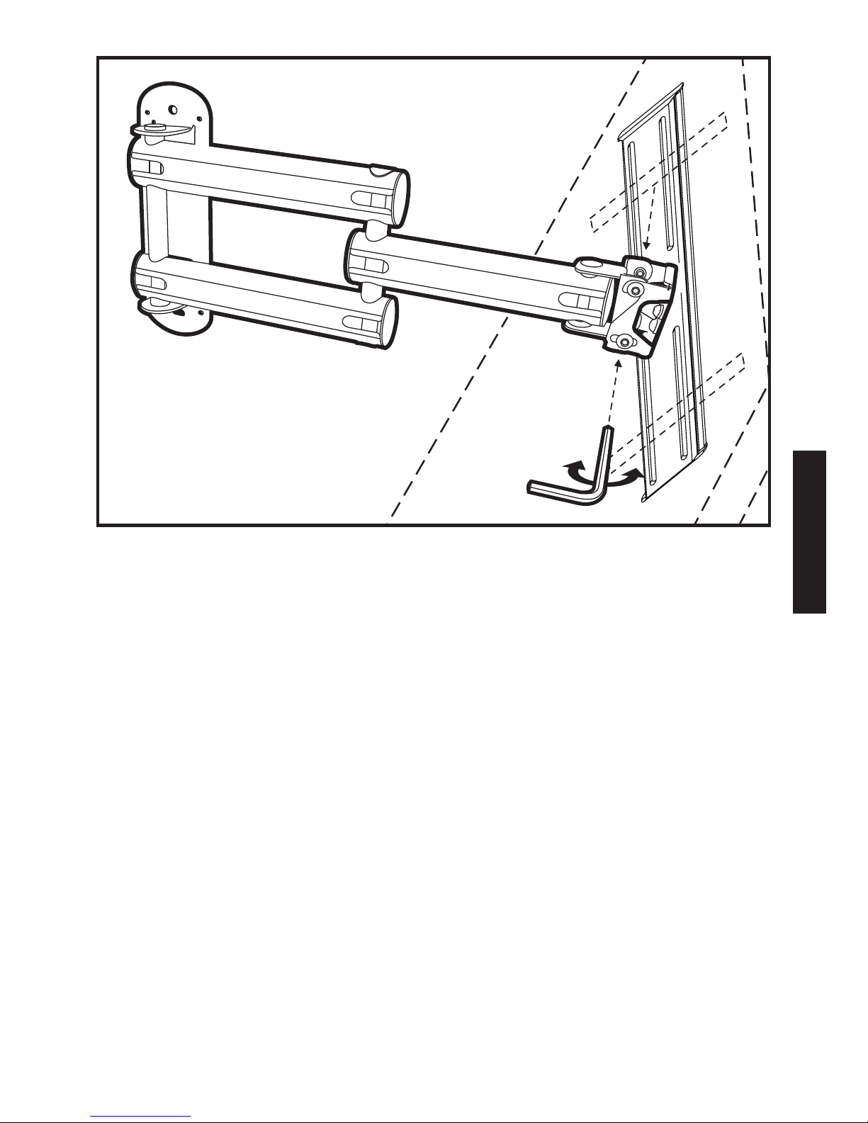
ESPAÑOL
85
Page 90
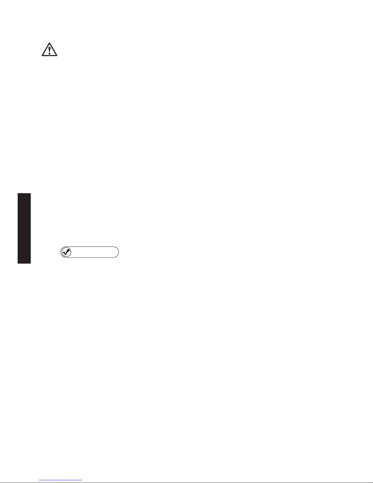
ESPAÑOL
86
Ajuste de la posición horizontal del televisor
EVITE aojar demasiado los tornillos de ajuste
de la tensión en la parte trasera de la placa del
televisor. La placa del televisor y el televisor
podrían soltarse de la base.
Encuentre los tres tornillos de tensión en la parte 1)
trasera de la placa del televisor, como se muestra.
Gire los tornillos izquierdo y derecho en sentido 2)
antihorario para proceder a graduar la posición
horizontal del televisor.
Si la rotación todavía está restringida después 3)
de aojar los tornillos izquierdo y derecho, aoje
el tornillo central de ajuste de la tensión.
Comprobación de
horizontalidad
4) Mueva la pantalla hacia la izquierda
o hacia la derecha con la mano. Una vez que
el televisor se encuentre en la posición deseada,
utilice el nivel de burbuja suministrado para
asegurarse de que haya quedado completamente
horizontal. Gire los tornillos en sentido horario para
apretarlos de nuevo.
Page 91
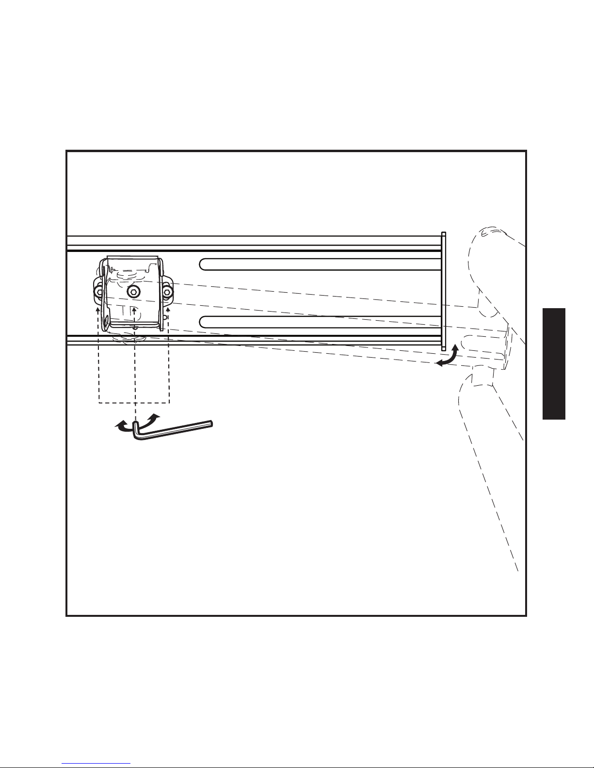
ESPAÑOL
87
Page 92

ESPAÑOL
88
Colocación del cable de alimentación
eléctrica de su televisor y de los cables
de AV a través de sistema de organización
de cables de la base
Una vez que la base esté completamente instalada 1)
sobre la pared y que su televisor esté sujeto
adecuadamente a la base, extienda completamente
los brazos pivotantes Z-Fold™.
Mueva la base completamente hacia la izquierda 2)
o hacia la derecha. Eso le facilitará el deslizar las
cubiertas de los canales de los cables de los tres
brazos oscilantes.
Conecte el cable de alimentación eléctrica al televisor 3)
(si es un cable que se puede separar).
Quite las cubiertas de los canales de los cables de los 4)
brazos oscilantes, como se muestra a la derecha.
Pase el cable de electricidad del televisor a través del 5)
canal inferior.
Para hacer las conexiones al televisor, pase los cables de 6)
audio y video que vienen de la pared, del descodicador,
del receptor de audio/video o de cualquier otra fuente
a través del canal superior y del segundo brazo, como
se muestra a la derecha.
Al terminar, coloque de nuevo las cubiertas de los 7)
canales de los cables en su lugar. Fije a presión las tapas
de los extremos del brazo oscilante, como se muestra.
Page 93
ESPAÑOL
89
Felicitaciones
Ya instaló correctamente su base articulada
Monster FlatScreen™.
Visite www.MonsterCable.com/FlatScreen para conocer
otros innovadores productos Monster FlatScreen.
cubiertas de los
canales de los cables
tapas para
los extremos (5)
Page 94

ESPAÑOL
90
GARANTÍA LIMITADA PARA EL CONSUMIDOR
Monster, LLC., 7251 West Lake Mead Blvd., Las Vegas, NV 89128, USA, (415) 840-2000
(“Monster”) le extiende a Usted esta Garantía Limitada. Los estatutos o el derecho
consuetudinario podrían otorgarle a Usted otros derechos o compensaciones, que
no se verán afectados en virtud de esta Garantía Limitada.
DEFINICIONES
El signicado de “Uso adecuado” es el uso del Producto (i) en el interior de una casa
o vivienda, (ii) para nes privados (distintos de usos comerciales), (iii) en conformidad
con todas las leyes locales, estatales o nacionales correspondientes (incluyendo, con
carácter enunciativo pero no limitativo, las normas de instalaciones eléctricas y las de
construcción), (iv) de acuerdo con las recomendaciones del fabricante, las instrucciones
en los materiales y la documentación que acompañan al Producto, y (v) si corresponde,
con la conexión a tierra adecuada.
El signicado de “Distribuidor Autorizado” es cualquier distribuidor, revendedor
o minorista que (i) estaba autorizado debidamente para hacer transacciones en la
jurisdicción en la que le vendió el Producto a Usted, (ii) tenía la aprobación para venderle
el Producto según las leyes de la jurisdicción en la que Usted compró el producto, y (iii) le
vendió el Producto en condiciones de nuevo y en su embalaje original.
El signicado de “Reclamación formal por la garantía” es una reclamación realizada
de acuerdo a la sección “Reclamaciones formales por la garantía” en este documento.
El signicado de “Producto” es un producto (i) que aparece en la lista de la tabla
de especicaciones más abajo, (ii) que Usted compró a un Distribuidor Autorizado,
en condiciones de nuevo y en su embalaje original, y (iii) cuyo número de serie, si lo
hubiera, no haya sido quitado, alterado o borrado.
El signicado de “Defecto en el producto” es el de una insuciencia del Producto
que haya existido en el momento en que Usted recibió el Producto de un Distribuidor
Autorizado y que origine una falla del Producto en cuanto al comportamiento indicado
por la documentación de Monster que acompaña al Producto, a menos que dicha
falla haya sido causada total o parcialmente por (a) usos distintos al Uso Adecuado, (b)
transporte, negligencia, mal uso o abuso por personas distintas a los empleados de
Monster; (c) alteraciones, manipulaciones o modicaciones del Producto por personas
distintas a los empleados de Monster; (d) accidentes (distintos a fallas que podrían
considerarse Defectos del Producto); (e) labores de mantenimiento de servicio en el
Producto hechas por personas distintas a los empleados de Monster; (f ) contacto del
Producto con el calor, luces brillantes, luz del sol, líquidos, arena u otros contaminantes;
o (g) actos fuera del control de Monster incluyendo, con carácter enunciativo pero no
limitativo, los actos de Dios, incendios, tormentas, terremotos o inundaciones.
Page 95

ESPAÑOL
91
El signicado de “Período de Garantía” es el período de tiempo durante el cual
Monster debe recibir su Reclamación Formal por la Garantía. Los distintos Períodos
de Garantía correspondientes a los Defectos en el Producto se denen en la Tabla
de Especicaciones que se encuentra más adelante en este documento. El período
de garantía se inicia en la fecha en la que Usted adquirió o recibió (la más tardía) el
Producto de un Distribuidor Autorizado, según lo señale la factura, recibo de ventas
o nota de despacho del Distribuidor Autorizado. Si Usted no dispone de una prueba
escrita de la fecha de compra o de recepción, entonces el Período de Garantía se iniciará
tres (3) meses después de la fecha en la que el Producto salió de Monster o de su
fábrica según lo evidenciado en los registros de Monster. El Período de Garantía naliza
después del lapso de tiempo denido en la Tabla de Especicaciones, o después de
que Usted haya transferido la propiedad del Producto, lo que ocurra primero. Además,
Usted debe llamar a Monster y obtener un Número de Autorización de Devolución
(como se indica en “Cómo hacer reclamaciones”) dentro de los dos (2) meses siguientes
a que Usted haya descubierto un Defecto del Producto (o debió haberlo descubierto si
tal Defecto del Producto era evidente).
La denición de “Usted” es la primera persona natural que adquirió el Producto en su
embalaje original y de un Distribuidor Autorizado. Esta Garantía Limitada no se aplica
a personas o entidades que hubieren comprado el producto (i) usado o sin embalaje,
(ii) para la reventa, alquiler u otro uso comercial, o (iii) de alguien diferente a un
Distribuidor Autorizado.
ALCANCE DE ESTA GARANTÍA LIMITADA
PRODUCTOS. Si un Producto incluía un Defecto en el Producto cuando Usted lo
adquirió de un Distribuidor Autorizado y Monster recibe un Reclamo Formal de
Garantía de Usted dentro de los dos (2) meses siguientes a que Usted haya descubierto
tal Defecto en el Producto (o debió haberlo descubierto si tal Defecto en el Producto
era evidente) y antes de nalizado el Período de Garantía contra Defectos en el
Producto correspondiente al Producto afectado, entonces Monster le ofrecerá una
de las siguientes compensaciones: Monster (1) reparará o, a su exclusivo criterio,
reemplazará el Producto, o (2) le devolverá el precio de compra que Usted pagó al
Distribuidor Autorizado por el producto afectado en caso de que la reparación o
reemplazo no sea viable comercialmente o no se pueda hacer oportunamente. NOTA:
MONSTER NO ACEPTA RESPONSABILIDAD ALGUNA POR NINGÚN DAÑO INCIDENTAL,
DERIVADO O INDIRECTO CONFORME A LOS TÉRMINOS DE ESTA GARANTÍA LIMITADA
CONDICIONES GENERALES
LEGISLACIÓN Y JURISDICCIÓN. Esta garantía limitada y todo litigio que surgiese en
virtud de o en conexión con esta Garantía Limitada (“Litigios”) se regirán por las leyes
del estado de California, EE. UU., excluyendo conictos de principios jurídicos o legales y
excluyendo la Convención para la Venta Internacional de Bienes. Los tribunales situados
en el Estado de California, EE. UU. tendrán jurisdicción exclusiva sobre todo litigio.
Page 96
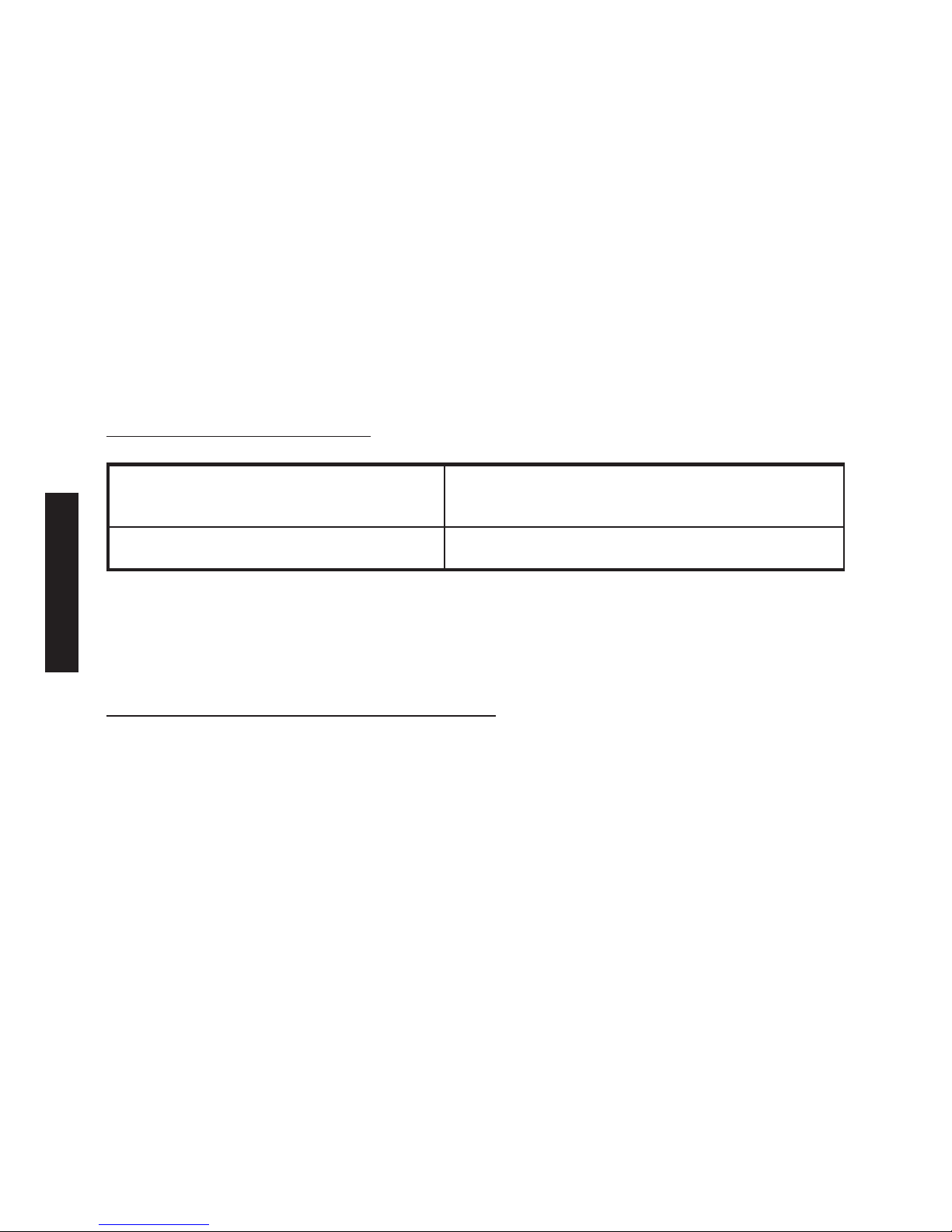
ESPAÑOL
92
OTROS DERECHOS. ESTA GARANTÍA LE OTORGA DERECHOS LEGALES ESPECÍFICOS
Y USTED PODRÍA TENER TAMBIÉN OTROS DERECHOS QUE VARÍAN DE UN ESTADO A
OTRO Y DE UNA JURISDICCIÓN A OTRA, LOS CUALES NO SE VERÁN AFECTADOS EN
VIRTUD DE ESTA GARANTÍA LIMITADA. ESTA GARANTÍA SE EXTIENDE SÓLO A USTED
Y NO PUEDE SER TRANSFERIDA NI HEREDADA. Si alguna disposición de esta Garantía
Limitada está fuera de la ley, es nula o no puede ser exigida legalmente, se considerará
que dicha disposición es susceptible de eliminación y las disposiciones restantes de la
Garantía Limitada no se verán afectadas. En todo caso de discrepancia entre la versión
en inglés y otras versiones de esta Garantía Limitada, se considerará como válida a la
versión en inglés.
REGISTRO. Haga el registro de su producto en www.MonsterCable.com.
Los derechos establecidos por la Garantía no se ven afectados si no se hace
el registro del producto.
TABLA DE ESPECIFICACIONES
Modelo del producto Período de Garantía del Producto
Base articulada mediana De por vida
*El signicado de “De por vida” es el lapso menor de tiempo entre la vida del comprador
original (persona natural) del Producto, o durante todo el tiempo que el comprador
original sea el propietario del Producto.
RECLAMACIÓN FORMAL POR LA GARANTÍA
CÓMO HACER RECLAMACIONES. Usted debe seguir estas instrucciones en caso
de que se hayan producido daños al Producto: (1) Llame a Monster dentro de los dos
(2) meses siguientes al momento que usted descubra el Defecto del Producto
(o debió haberlo descubierto si tal Defecto del Producto era evidente); (2) Suministre
una explicación en detalle de cómo ocurrió el daño; (3) Obtenga un Número de
Autorización de Devolución; (4) Devuelva los Productos, a Monster habiendo Usted
pre-pagado el transporte (que le será reembolsado si usted tiene derecho a una
compensación según los términos de esta Garantía Limitada), para la comprobación
de los daños, junto con una copia de su recibo original de venta y prueba de compra
(la etiqueta UPC o la nota de despacho) de dichos Productos, el formulario de
reclamación totalmente lleno y el número de la autorización de devolución impreso
en el exterior del embalaje de devolución (el formulario de reclamación incluirá
instrucciones para la devolución).
NÚMEROS TELEFÓNICOS. Si adquirió el producto en los Estados Unidos, en Latinoamérica o en la región Asia-Pacíco, comuníquese con Monster, LLC (455 Valley Drive,
Brisbane, CA 94005) al teléfono 1 877 800-8989. Si adquirió el producto en cualquier
otro lugar, comuníquese con Monster Technology International Ltd., Ballymaley
Page 97

93
Business Park, Ennis, Co. Clare, Ireland. Puede enviarnos comunicaciones escritas o
utilizar los siguientes números telefónicos: Canadá 866-348-4171, Irlanda 353 65 68 69
354, Bélgica 0800-79201,República Checa 800-142471, Dinamarca 8088-2128, Finlandia
800-112768, Francia 0800-918201, Alemania 0800-1819388, Grecia 00800-353-12008,
Italia 800-871-479, Países Bajos 0800-0228919, Noruega 800-10906, Rusia 810-80020051353, España 900-982-909, Suecia 020-792650, Reino Unido 0800-0569520
PROCEDIMIENTOS ULTERIORES. Monster determinará si existe un Defecto
en el Producto. Monster puede, a su exclusivo criterio, indicarle que obtenga
un presupuesto de reparación en un centro de servicio técnico. Si se solicita un
presupuesto de reparación, se le indicará la forma de enviar correctamente dicho
presupuesto y también la factura correspondiente a Monster para su pago.
Todo cargo por reparaciones podrá ser negociado por Monster.
CRONOGRAMA. Si usted envía una Reclamación Formal por la Garantía y cumple
totalmente todos los términos y condiciones de esta Garantía Limitada, Monster hará
su máximo esfuerzo para suministrarle una compensación dentro de los treinta
(30) días siguientes a la recepción de su Reclamación Formal por la Garantía (si usted
es residente de los Estados Unidos – cuarenta y cinco (45) días si usted es residente
de cualquier otro país), a menos que el proceso se retrase por factores fuera del
control de Monster
Ver.072109 – GLOBAL ©2003–2009 Monster, LLC
Page 98

Page 99

PORTUGUÊS
95
NOTA DO HEAD MONSTER
OBRIGADO por adquirir o Suporte
Articulado Monster Flatscreen™.
Este suporte reete a nossa paixão
em criar as soluções mais inovadoras
e práticas em AV no mercado para
melhorar a sua experiência de assistir
televisão. Os Suportes Articulados
Monster Flatscreen são seguros,
sólidos e fáceis de instalar. Os braços
oscilantes extensíveis e uma junta pivô
onidirecional proporcionam possibilidades quase innitas
de assistir televisão. Comece a aproveitar a TV nos nossos termos
- quando, onde e como você quiser assistir.
Noel Lee,
O Head Monster
Page 100
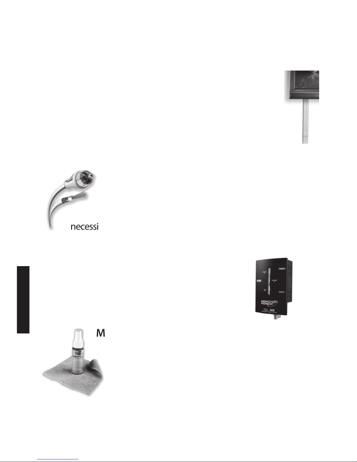
PORTUGUÊS
Mais Excelentes Produtos da Monster FlatScreen
™
Tenha o Visual que Você Deseja e o Desempenho que
Você Precisa.
Gerenciador de Cabos Monster FlatScreen CleanView
™
Esconde aquela confusão de os e cabos, criando
uma aparência limpa e elegante. Fácil de instalar com
coberturas que podem ser pintadas para combinar com
qualquer decoração.
Monster FlatScreen Cables
™
Os Cabos Monster Flatscreen são compactos
e exíveis para fácil distribuição e instalação.
Tecnologias exclusivas patenteadas da Monster
oferecem o desempenho avançado de que você
necessita de sua TV de tela plana.
Monster FlatScreen PowerProtect™ e PowerCenters
™
Proteja sua TV de tela plana contra sobrecargas
perigosas e picos de energia e maximize o
desempenho com a proteção contra sobrecarga
Monster Tri-Mode® e ltragem de HD Clean Power®,
projetadas especicamente para HDTVs.
Monster FlatScreen Clean
™
Limpe com segurança sua TV de tela plana LCD ou
plasma sem manchá-la, arranhá-la ou respingá-la.
Um pano ultramacio de MicroFibra não vai
arranhar a cobertura delicada da tela.
Para maiores detalhes sobre nossos produtos da Monster
FlatScreen, visite MonsterCable.com/FlatScreen
 Loading...