

Page 1

Series 3000
Model R-197AV
Audio/Video Relay Panel
With Ethernet Interface
Instruction Manual
CATV Switching and Control EAS
585-765-2254 fax 585-765-9330
100 Housel Ave. | Lyndonville | NY | 14098
www.monroe-electronics.com
Printed in USA Copyright Monroe Electronics, Inc.
Specifications subject to change without notice
P/N 1340230
02/06/2012
Page 2

Table of Contents
Specifications 3
General Description 4
General Instructions 6
Applications
General Switching Audio 7
Connections 9
Ethernet Interface Setup 10-18
EAS Switching 19
DASDEC Config 20-24
2
Page 3

Power Requirement
100-240V AC +/- 2%, 50/60Hz
supplies +12V DC @ <300mA
(UL approved wall supply included.)
Control Inputs
Contact Closure to GND or logic input
Absolute Maximum Input Volt age +12 VDC
Logical High Input Volt age +7 VDC
Logical Low Input Volt age +2 VDC
Ethernet Input
10/100 baseT with Embedded Server
Audio Relays Cont act Rating:
30 VDC max; 1A max
Specifications
Video Relays Contact Rating:
+60 dBmV RF, 0 to 1 GHz
Physical
1.75” H X 19” W X 7” D, 1 RU
Weight 5 lbs.
Optional Redundant Power Supply
Accessories Included with Instrument
Power Supply
Mating connectors
Mounting Kit
Manual/Data Sheet on CD
3
Page 4
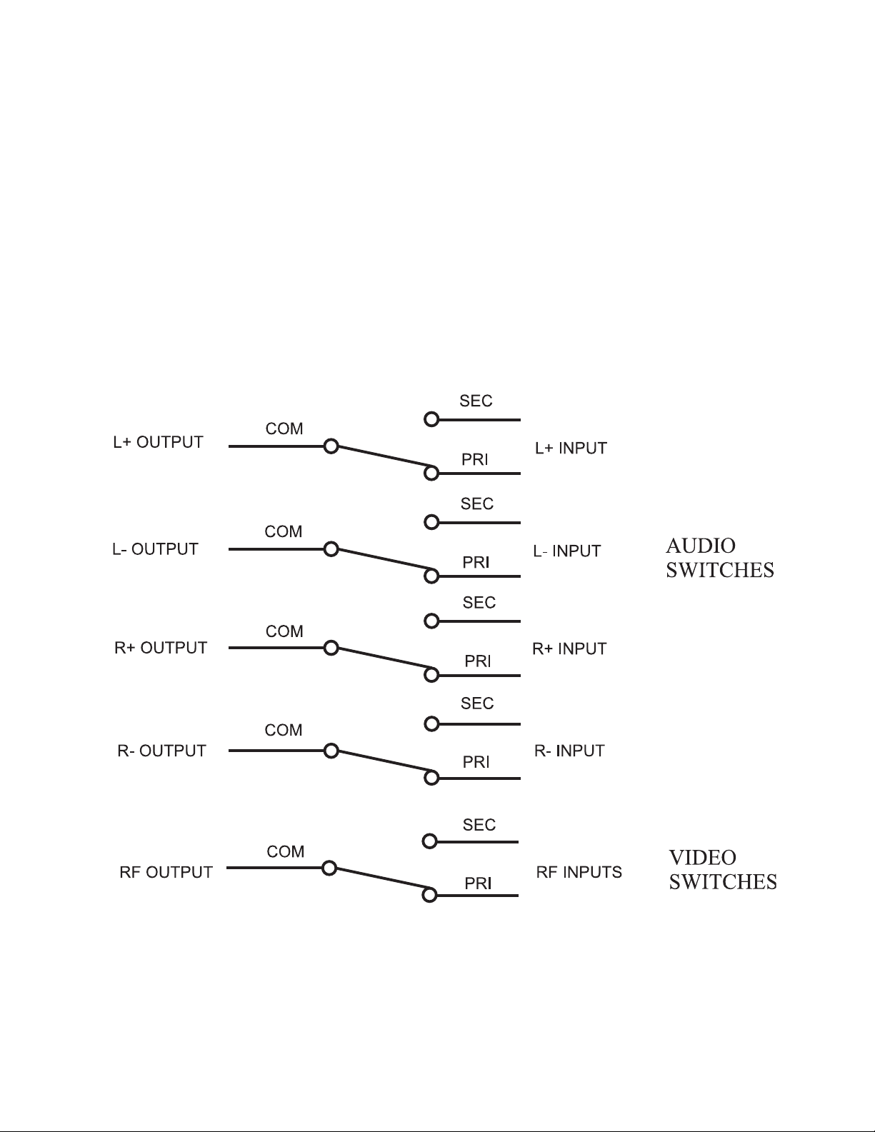
General Description
In its simplest form, the R-197A V is nothing more than a multi-contact relay capable of switching away from signal A and connecting to signal B. There are 4 independent relay sections in
each R-197A. All sections of the relay are of the mechanical type with no active circuitry involved in the signal path.
4
Page 5
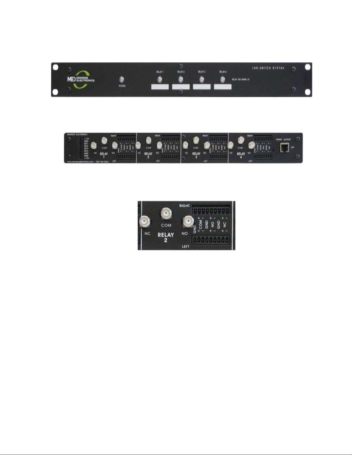
Front Panel View
Rear Panel View
Section View
5
Page 6

General Instructions
Mounting:
The R-197A V requires a minimum of 1.75 vertical inches of space in a standard 19” wide EIA
equipment rack. Slide the unit into the rack frame and secure it, using the 3000R/22M mounting hardware supplied with the unit.
Connections:
1. Connect the audio signals to screw terminals of the same switch group, ensuring that the left
and right channels for the default audio are connected to the L NC + and -, and the
R NC + and -, and the signals for the alternate signal are attached to the
L NO + and - and the R NO + and - connectors. The L OUT + and - and the R OUT
+ and - are routed to the modulator or other destination of the audio signals.
Connect the Video (or RF/IF) signals to the same switch group as their audio signals, with
the default (or primary) signal connected to the NC ‘F’ connector , and the alternate signal is
connected to the NO ‘F’ connector. The cable to the modulator (or combiner, etc.) is connected to the COM ‘F’ connector .
2. Connect the +12 VDC lead (white) from the power supply to the +12v terminal at the top of
rear panel connector , and the black lead to the adjacent GND terminal. Refer to the diagram
on page 9. Plug the power supply into a 90 - 240V AC power outlet, and the unit is ready to
function.
3. T o actuate a relay section with a contact closure, connect the contact s
between each relay control input screw terminals (SW1–SW4) and ground (GND) screw
terminal. Refer to the rear panel connections illustration and the applications section of this
manual.
4. T o actuate a relay via Ethernet control, enter the URL (IP address) of the device into the
address bar of any browser , select “Switch Control”, and click on the relay section to actuate
(or in-actuate).
Operation
When the contact closure for the appropriate Relay Unit is closed, the output (Com)connection
is switched from the default input (NC) to the alternate input (NO).
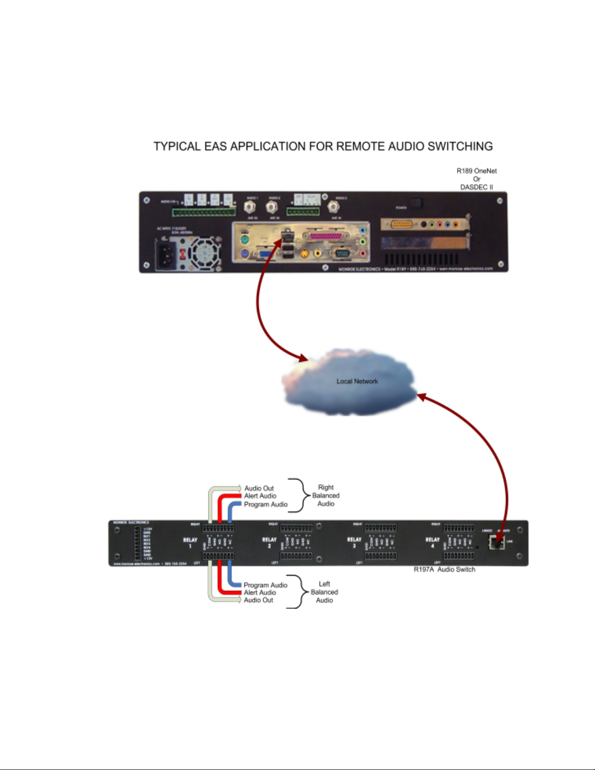
Activation of any of the 4 relay sections may be accomplished by external contact closure,
open collector transistor, web browser or logic signal. In most applications, the R-197AV is
connected to another device that provides the activation signal. The most popular applications
for controlling the R-197AV are time control, LAN control, and DTMF (telephone) control.
Other devices, such as the One-Net or DASDEC II, may be used for controlling the R-197AV
as long as they provide the proper signaling.
Please note: that the contact closure input, if it is pulled to ground to switch to secondary , will
supersede the ethernet control inputs if they are set to primary . However , if the contact closure
inputs are set to primary , the ethernet control inputs may switch to secondary .
6
Page 7
Appplications
General Switching
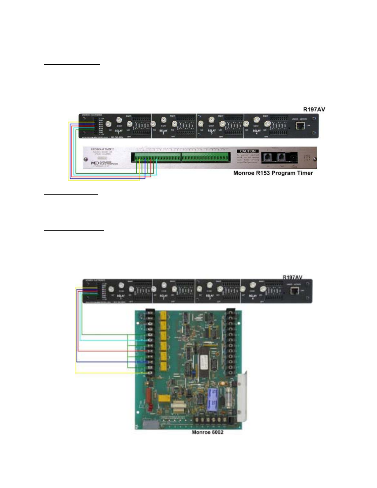
Control by Time
The R-197A V can be directly connected to Monroe R153 program timers so that program
signals can be switched according to time schedules at the broadcast point or headend. The
switch-timer interface would look something like the following graphic.
Control by LAN
The R-197A V may also be easily controlled by anyone on the local network with a web
browser. The unit has an included server, with a fixed IP address. The interface is self explanatory . Refer to LAN Setup for configuring this control function.
Control by DTMF
The R-197A V can also be operated by one of the Monroe DTMF remote controls that allow
switch operation by DTMF signaling from a standard dial-up telephone (model 6002) or by a
dry 600 ohm audio line (model 6003). Connections for this application are shown in the following graphic.
7
Page 8
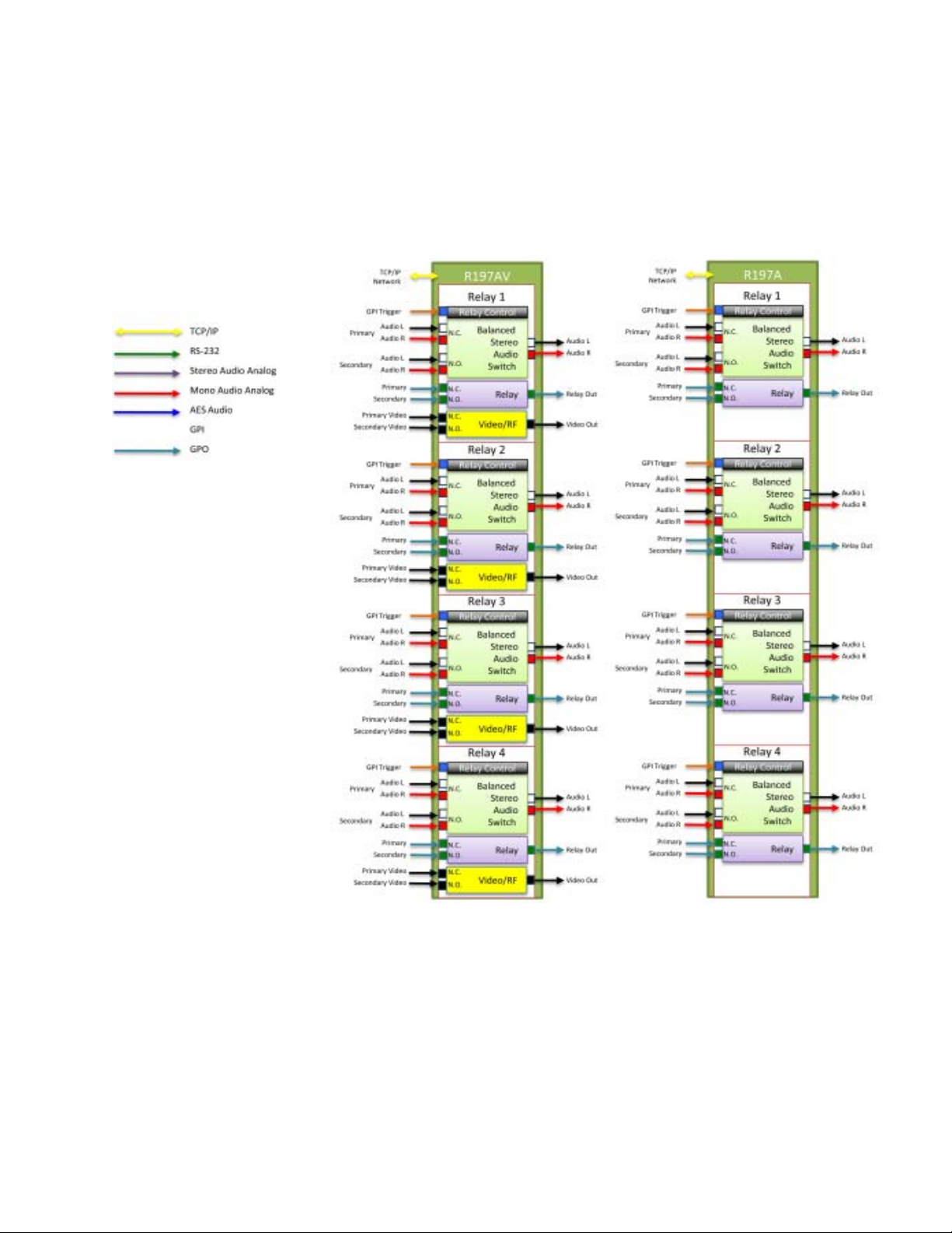
This diagram shows the inputs/outputs of the R197A and the R197AV.
8
Page 9

This diagram shows, more specifically, the input and outputs connections for the R197A and R197AV.
9
Page 10
Ethernet Interface Setup
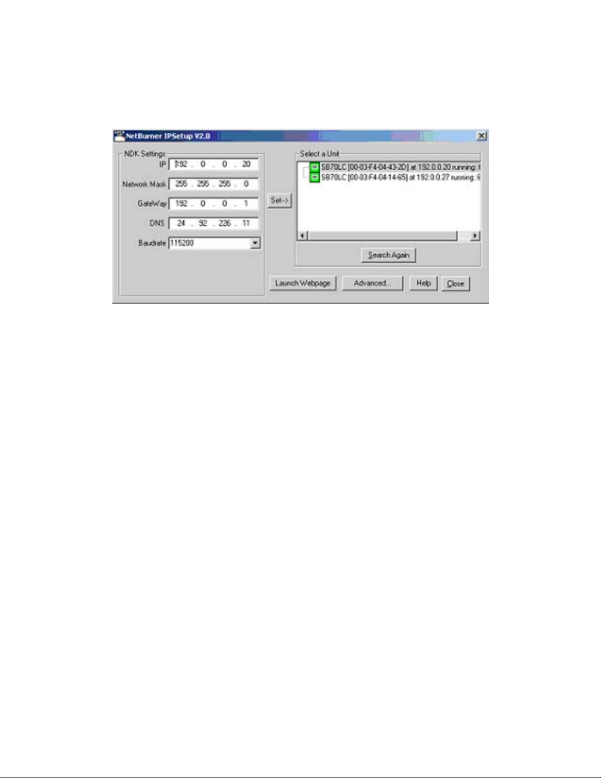
On the CD included with the unit is a program entitled Netburner IPSetup V2.0.
After ensuring that the R-197A V to be set up is powered up, and is connected to your computer,
or to your network, open this program. [If connecting directly from your computer, use a crossover
cable.]
Notice that two netburner devices have been detected.
If yours has not been set up, it will have a default of 192.168.0.2. This should be one of the
choices shown. However, if the IP address has been changed for testing purposes, it may be
another address such as 192.0.0.20..
T o change this to the IP address you desired, merely type into the NDK Settings the address IP,
the Gateway and the DNS on the left side to program this address, and then select the default
address. Y ou would then click on Set, and the program will modify your device.
[Another way to modify the address of the server in the unit is to enter the present IP address in a
browser window. Then go to “Setup” in the ensuing screen. If the unit asks for
a password, enter r197set. Then enter the IP desired, the Gateway and the DNS to be used,
click on Save and restart the device by turning the power on and off. ]
Select Close to finish.
If you forget the IP address used for the unit, you must reset the unit to the default address.
Remove power. Using a p aper clip, press and hold the reset button down, then re-apply power
to the board. If the button is held down for at least 2 seconds, but less than 8
seconds, Relay1 turns on. Releasing the button during this time will reset the passwords to
default: “r197c” for control, “r197set” for setup, and all settings in the unit will also be reset. If
the button is held down between 8 - 29 seconds, Relay2 will be turned on. Releasing the
button during this time will reset the IP to default: 192.168.0.2, and the passwords and data
will be reset as described before. (If you continue to hold the button down pass 30 seconds,
NOTHING will be reset.)
10
Page 11

Y ou may now use the included Setup on the server IF you are directly connected to the unit.
If you are connected to the unit through a network, you must use the ‘NetBurner ip setup’ program
supplied with your unit on the included CD. This program is also available on the NetBurner web
page.
Once you have set the IP address for your unit, enter it into your browser , and
Y ou will see the following screen:
11
Page 12

T o set the parameters in the R197A, click on ‘Setup”, and the following screen will appear:
12
Page 13

Select ‘Password’, the follwing screen appears:
The default password for the R197A is r197set, all lower case.
A User Name is not required.
13
Page 14

After clicking ‘Log In’, the following screen appears:
Note that you may change, and enable if desired, the Control Password,
and change the Setup Password here.
If you have made changes, click the Save button, and return to the setup screen.
14
Page 15
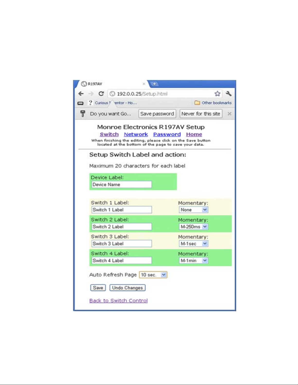
Select the Switch link, we see this page. Note we are allowed – but not required –
T o set labels for the device and each switch. We may also configure each switch for latching –
select none – or momentary , with the length of the closure selectable as shown.
Again, select Save to retain the choices in the R197A.
15
Page 16

Note also, that you may select the frequency of refreshing the switch control page on this
Setup page.
16
Page 17

Changing network settings after the initial setting of the IP address, it is
accomplished here. This page is reached by clicking on the ‘Network’ tab in setup.
17
Page 18

After completing the setup for the device, and installing it in the system, the operator brings up
the Switch Control page, and sees the screen below .
Note that manual control of the switch is accomplished by clicking on the round display button for
each switch. If the display button is unlit, the switch is in the primary mode.
If it is lit, the switch is in the secondary mode.
Auto refresh can be disabled if desired.
18
Page 19
EAS Switching
(VIA DAS DEC)
19
Page 20

EAS use with Digit Alert Systems DASDEC
Configuring the DASDEC
Each switch of the R197A V is network controlled by the DASDEC over a TCP/IP (Ethernet)
connection. Each of the R197A V program switches is tied to a Net GPIO relay control setting in the DASDEC. Setting NET GPIO Output Relay 1 will close the Channel 1 AES switch;
NET GPIO Output Relay 2 will close Channel 2 AES switch, etc. When any switch is closed
the incoming analog audio to the Master input is digitized and output on each closed channel.
1. Once the R197AV is configured with the
proper network settings connect it to a
network where the DASDEC can “see”
the device – i.e. the same network or , if
the DASDEC has the EXP-3NIC or
EXP-3NICGIG Ethernet expansion
directly (via a crossover cable to one of
the expansion ports). Note the port
numbers must match the configuration
settings. Refer to the picture for port
numbering.
2. Log onto the DASDEC box either remotely or locally from the web browser interface. The
default is “Admin” as the User Name and “dasdec” as the password. (note: User Name and
Password are case-sensive)
3. If the R197A V is on a common network (ie through an Ethernet switch to the DASDEC skip
to Step 12. If the R197A V is connected to one of the other Ethernet ports 2 - 4 follow the steps
below to ensure the network settings are correct.
4. Go to Setup > Network > Configuration
5. Enable the network inteface which is connected to the R197A V by selecting the box next to
the [number] Network Interface.
20
Page 21

6. If using the 2nd network interface select the Static (Manually Configure) radio button,
otherwise continue to Step 7.
7. In the Manual Config Options box enter an IP Address that differs by at least one number in
the last octet from the R197A V’s IP address. As an example if the R197AV’s IP address is
192.168.1.2 enter 192.168.1.3.
8. Enter enter the SAME Netmask number set in the R197A V .
9. Y ou can ignore the host name.
10. Click Accept Changes /Restart Network further down the page. The DASDEC will restart
with the new network settings.
11. Log in again
12. Go to Setup > Net Alert s > Net GPIO. Click on the Add NETGPIO Client Interface button
as shown in Figure . A gray box will appear with additional information
Do not use the same IP numbers.
Reference source not found
14. Put the IP address of the previously configured R197A V
in the IP Address box. The DASDEC will immediately try to
ping the device. If it cannot “find” the unit a red warning box
(Error: Reference source not found) will be displayed.
Enter the proper IP address to correct and the warning will
disappear.
13. Turn on the client by
selecting (clicking) in the
box ENABLE Client
Interface in the gray
area. When activated
additional parameters
can be accessed and
added as shown in
21
Page 22

15. The Name box will default to NETGPIO x where “x” is the next number in the sequence.
Y ou can leave the current name or type a different name for this device. We’ll use R197AV
for this example. Once saved this name will appear in the pull down menu and on the
station configuration table later .
16. Using the pull down menu next to Model select WebRelay Quad/ Monroe-R190A/
R197
17. If, and only if, the R197A V was configured with a “control” password type this in the box
adjacent Password. NOTE: The control password is different from the configuration ac-
cess password and is <<blank – no characters>> from the factory .
18. Using the pull down menu select During EAS Audio Playout under the NET GPIO
Output Relay 1. Af ter this is selected the FIPs and EAS filtering boxes will appear on to
the right. Only very rare cases should these filters be used, so typically there is no need to
modify these configurations
19. Repeat Step 18 for each NET GPIO Output Relay 2, 3 and 4.
20. Click Accept Changes at the bottom of the screen.
21. Go to Setup > Decoder > Forwarding
22. Scroll down to the MultiStation Interface Configuration section.
22
Page 23

23. Select the second2active (enabled) station in the Select Station Configuration
Interfaceusing the pull down. (Note: Active (enabled) st ations are identified with a asterisk [*]
preceding the name.
24. On the far right side of settings table will be the Net GPIO ‘R197A V list as highlighted in
Error: Reference source not found. Recognize the name R197A V between the quotes is
the name previously assigned to the client. This may be different if another name was used.
25. In the Net GPIO ‘R197A V’ table select the Net GPO number that corresponds to the switch
wired for this station. Clicking on this selection will highlight the selection and assign this
closure to this station.
2
This assumes that station one is configured to switch using the internal DASDEC program switch, therefore
stations 2, 3, 4 & 5 would be externally switched.
23
Page 24

26. In the Forwarding Audio Output Devices box click on Aux1 Audio Output.
27. Click Submit Selection Settings button at the bottom of the table (See Figure )
Figure Submit selections after assigning Net GPO port for the station.
28. As previously mentioned, each of the R197A program switches is tied to a Net GPIO relay
control. Setting NET GPIO Output Relay 1 will close the Channel 1 AES switch, NET GPIO
Output Relay 2 will close Channel 2 AES switch, etc., routing and converting the Master input
to the output of the closed channel(s).
29. Repeat Steps 23-26 for each of the configured st ations.
24
 Loading...