


Series 3000
Model R-165A
Audio/Video – IF/RF Relay Panel
Instruction Manual
CATV Switching and Control
585-765-2254 fax 585-765-9330
100 Housel Ave. | Lyndonville | NY | 14098
www.monroe-electronics.com

Table of Contents
Specifications 3
General Instructions 4
Applications 5
Frequency Charts 9
Printed in USA Copyright Monroe Electronics, Inc.
Specifications subject to change without notice
P/N 1340224
7/27/10
2

Specifications
RF Isolation
> 60 dB @ 950 MHz.
Attenuation
+/- 1 dB 0 to 950 MHz
See Attached Graphs.
Power Requirement
100-240VAC +/- 2%, 50/60Hz
supplies +12V DC @ <300mA
(UL approved wall supply included.)
Control Inputs
Contact Closure to GND or logic input
Absolute Maximum Input Voltage +12 VDC
Logical High Input Voltage +7 VDC
Logical Low Input Voltage +2 VDC
Max Sink Capability
<2.4 mA
Aux Relays Contact Rating:
30 VDC max; 1A max
Physical
1.75” H X 19” W X 7” D, 1 RU
Weight 5 lbs.
Optional Redundant Power Supply
Accessories Included with Instrument
Power Supply
Mating connectors
Mounting Kit
Manual/Data Sheet on CD
3

General Instructions
Mounting:
The 3000R-165 requires a minimum of 1.75 vertical inches of space in a standard 19” wide
EIA equipment rack. Slide the unit into the rack frame and secure it, using the 3000R/22M
mounting hardware supplied with the unit.
Connections:
1. The Video (or IF/RF) switches are mechanical relays, and connections to them
are made through 75
cable for the default signal to the NC (normally closed or primary) connector. Connect
your cable for your alternate signal - which you will substitute for the default
signal - to the NO (normally open or secondary) connector. Connect the cable to your
modulator or other destination to the COM (common or output) connector.
These connectors will switch either video signals, or may alternately be used to
switch high frequency signals, such as IF or RF. The frequencies useable are
shown on the frequency response charts included.
Of course, both inputs must be the same type of signal.
F connectors on the rear of the unit. Connect your
It is also permissible to use some relay sets for baseband video and some
for high frequency, since all switch modules are isolated.
2. If the signals being switched are baseband video, with audio following, connect the
audio signals to screw terminals of the same switch group, ensuring that the left and
right channels for the default audio are connected to the L NC + and -, and the
R NC + and -, and the signals for the alternate signal are attached to the L NO
+ and - and the R NO + and - connectors. The L OUT + and - and the R OUT
+ and - are routed to the modulator or other destination of the audio signals.
3. To actuate a relay section with a contact closure, connect the contacts
between each relay control input screw terminals (SW1–SW4) and ground (GND) screw
terminal. Refer to the rear panel connections illustration and the applications section of
this manual.
4. Connect the +12 VDC lead (white) from the power supply to the +12v terminal on the
rear panel, and the black lead to the GND terminal. Plug the power supply into a 90 264VAC power outlet, and the unit is ready to function.
5. If wiring balanced stereo audio (or balanced mono audio), and a tie point for the ground
wires is required, use the AUX2-COM and AUX1-COM terminals. These points are
floating if no connections are made to AUX2-NO and AUX2-NC and the AUX1-NC
points.
Operation
When the contact closure for the appropriate Relay Unit is closed, the output (Com)
connection is switched from the default input (NC) to the alternate input (NO).
4

APPLICATIONS
In its simplest form, the R165A is nothing more than a multi-contact relay capable of switching away
from signal A and connecting to signal B. There are 4 independent relay sections in each R165A. All
sections of the relay are of the mechanical type with no active circuitry involved in the signal path.
Each relay in the R165A is internally divided into 2 sections – video and audio. The video section is
constructed so that its reference impedance is 75 ohms. The relay used here is a high quality RF
type so that the video section can also be used for switching RF signals up to 950 MHz (see
specifications). It should be noted that the non-selected input into the video section is terminated into
75 ohms.
The audio section has contacts enough to provide full balanced stereo audio. In addition, there are
also 2 sets of auxiliary contacts for switching additional signals such as SAP or various tally
indicators. Check specifications for ratings on these contacts. A basic schematic of one of the four
relays is shown in the following graphic.
Activation of any of the 4 relays can be accomplished by external contact closure, open collector
transistor or logic signal. In most applications, the R165A is connected to other devices that provide
the activation signal. The most popular applications for controlling the R165A are time control, LAN

control, and DTMF (telephone) control. Other devices can be used for controlling the R165A as long
as they provide the proper signaling.
Control by Time
The R165A can be directly connected to Monroe R153 program timers so that program signals
can be switched according to time schedules at the broadcast point or headend. The switch-timer
interface would look something like the following graphic.
Control by LAN
The R165A can also be easily controlled by anyone on the local network with a web browser. This application requires
interfacing the R165A with a network remote control, Monroe model R190A. The connection scheme is very similar to the
one used with the R153 above and would look like the following graphic.
Control by DTMF
The R165A can also be operated by one of the Monroe DTMF remote controls that allow switch
operation by DTMF signaling from a standard dial-up telephone (model 6002) or by a dry 600 ohm
audio line (model 6003). Connections for this application are shown in the following graphic.
6

Matrix Configuration
The four sections of the R165A can also be wired to provide matrix switching capability from 1 X
3 to 1 X 5. Triggering of each section connects a specific input to the matrix output. Video
connections are shown in the following graphic. Audio connections would be made in a similar
fashion.
7
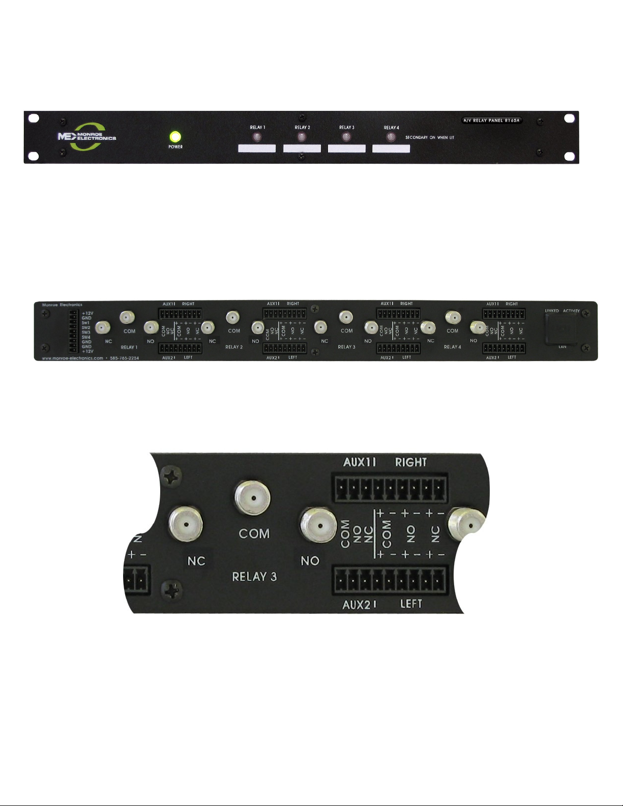
Front Panel View
Rear Panel View
Section View
8

This graph demonstrates the Return Loss of a typical switch input. Red shows the signal through the
Bridge with no connection. The yellow shows the signal when the bridge is terminated with a –26 dB
Loss load, and the green shows the return loss when the bridge output is connected to the normally
Closed switch input with a 75 ohm load on the output.
This graph shows attenuation of the signal from a switch that is ON to the output. [10 db per division,
0 to 1000 MHz]
This graph demonstrates the isolation from a switch that is OFF to the output. [10 db per division, 0 to
1000 MHz]
 Loading...