

Page 1

Instruction Manual
LAN Hub Controller
Model R190A
Monroe Electronics
100 Housel Ave
Lyndonville NY 14098-0535
800-821-6001 585-765-2254 fax 585-765-9330
www.monroe-electronics.com
1340221
021208
Page 2

Warranty 1
Specifications 2
Front and Rear View 3
SECTION 1 EAS - R190A being controlled by the R189 One-Net.
General Overview 4
Getting Started 5-9
Operation 10
Wiring Diagram 11
SECTION 2 REMOTE CONTROL - R190A being controlled by a PC.
Table of Contents
General Overview 13
Getting Started 14-18
Operation 19
Wiring Diagram 20
Page 3

Warranty
Monroe Electronics, Inc. warrants to the owners, each instrument and sub-assembly
manufactured by them to be free from defects in material and workmanship for a period
of two years after shipment from factory. This warranty is applicable to the original
purchaser only.
Liability under this warranty is limited to service, adjustment or replacement of defective
parts (other than fuses and batteries) on any instrument or sub-assembly returned to the
factory for this purpose, transportation charges prepaid.
This warranty does not apply to instruments or sub-assemblies subjected to abuse,
abnormal operating conditions, or unauthorized repair or modification.
Since Monroe Electronics, Inc. has no control over conditions of use, no warranty is made,
or implied as to the suitability of our product for the customer's intended use.
THE WARRANTY SET FORTH IN THIS ARTICLE IS EXCLUSIVE AND IN LIEU OF ALL
OTHER WARRANTIES AND REPRESENTATIONS, EXPRESS, IMPLIED OR
STATUTORY INCLUDING, BUT NOT LIMITED TO THE IMPLIED WARRANTIES OF
MERCHANTABILITY AND FITNESS. Except for obligations expressly undertaken by
Monroe Electronics, in this warranty, Owner hereby waives and releases all rights, claims
and remedies with respect to any and all warranties, express, implied or statutory
(including without limitation, the implied warranties of merchantability and fitness), and
including but without being limited to any obligation of Monroe Electronics with respect to
incidental or consequential damages, or damages for loss of use. No agreement or
understanding varying or extending the warranty will be binding upon Monroe Electronics
unless in writing signed by a duly authorized representative of Monroe Electronics.
In the event of a breach of the foregoing warranty, the liability of Monroe Electronics shall
be limited to repairing or replacing the non-conforming goods and/or defective work, and in
accordance with the foregoing, Monroe Electronics shall not be liable for any other
damages, either direct or consequential.
Return Policy to Factory
Materials returned to Monroe Electronics must have a Return Material Authorization
number. To obtain a RMA number, contact our A/V Switching & Control Customer Service
at 585-765-2254 or fax 585-765-9330. Customers have 30 days to determine that the
product ordered fills their need and performs as described in Monroe’s literature. Units
returned for approved repair or credit, must be in the original packaging including all parts
and paperwork plus be in very good physical condition. If not, the customer is billed the
cost to refurbish the unit and for missing accessories and merchandise. No products may
be returned for exchange or credit after 12 months of the shipment date. Monroe reserves
the right to repair or replace units under warranty.
1
Page 4

Specifications
Number of relays
4 Individually controlled rated for 1Amp at 28 Volts DC,
SPDT, NO, NC. Latch ON, Latch OFF, and Momentary from .1 to 86,400
Seconds.
Connections
10/100 baseT via RJ45
Power requirements
+ 5 volts DC; 94-240 VAC wall unit supplied
Indicator lights
One (1) to indicate Power on the front panel
Two (2) to indicate Connectivity, and Activity on the rear panel
Equipment Supplied
Power Supply
14 position plug
2
Page 5
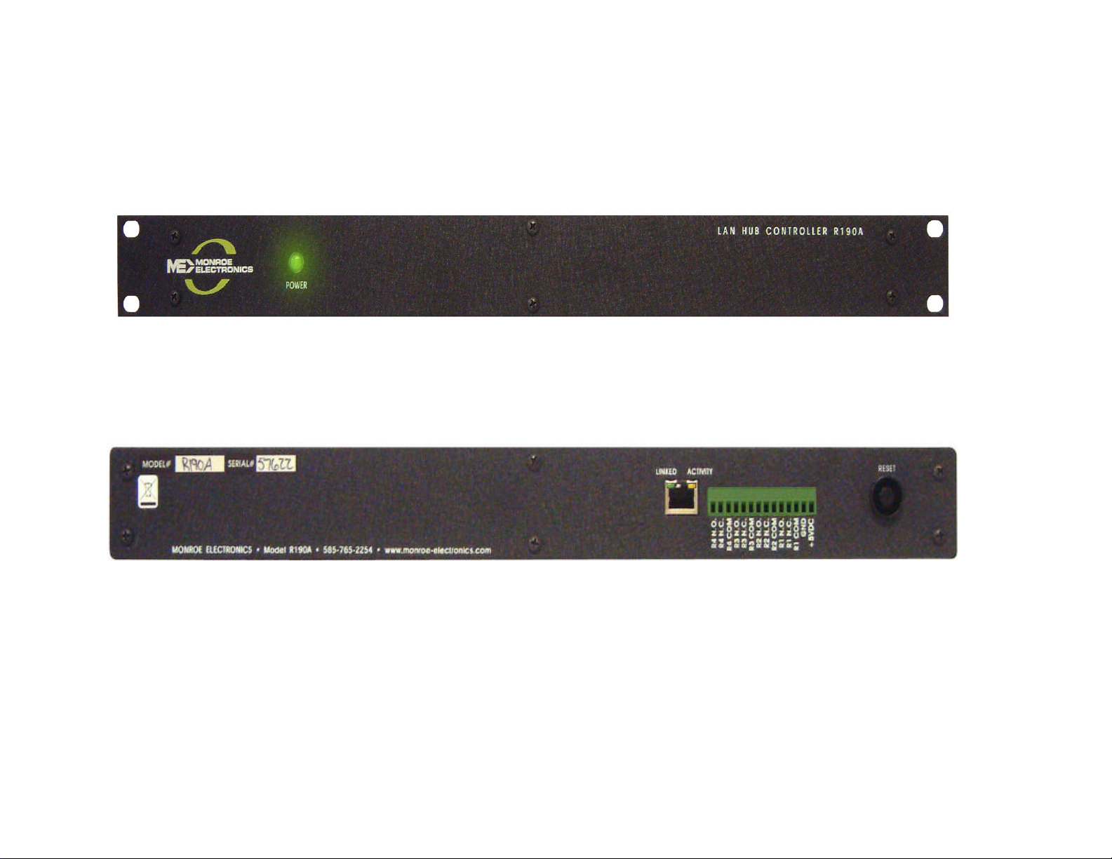
Front View
Rear View
3
Page 6
Section 1 EAS
4
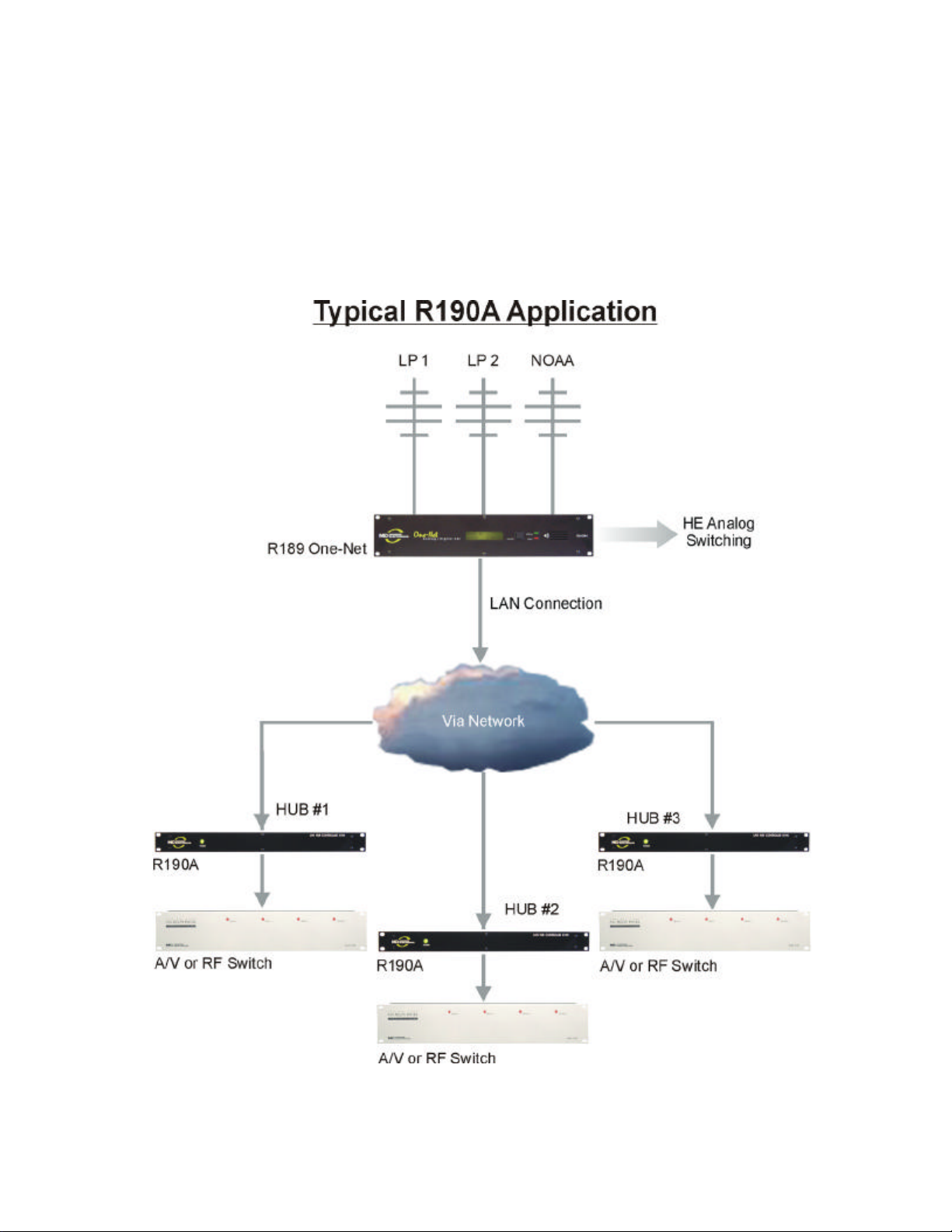
General EAS Overview
The R190A Hub Controller provides the ability to switch equipment at a remote site
or CATV Hub during EAS Alerts. It uses a LAN or WAN connection from a control
device such as the R189 One-Net EAS Encoder/Decoder. The unit has 4 relays
that are individually addressable. When used with the One-Net, they may be
triggered based on FIPS codes.
Page 7

Section 1 EAS
5
EAS Getting Started
Setting the IP address – The R190A comes with a default IP address of
192.168.1.2. One of the following methods can be used to access the device:
Directly connecting a networked host computer
Connect a CAT-5 network crossover cable to the RJ45 port at the back of the
R190A and to the RJ45 port of the network interface card (NIC) of a standalone
PC or notebook computer. Configure the standalone PC to use the static IP
address 192.168.1.3 with a net mask of 255.255.255.0. After the R190A
powers up it can be accessed via a Web browser on the host computer.
Launch a Web browser application and direct the URL to http:/192.168.1.2/.
The R190A will provide a gateway page and quickly redirect to the R190A
Home page. To edit the R190A’s IP address type the following IP address
http:/192.168.1.2/setup.html.
LAN connection with a networked host computer
Connect a standard CAT-5 network cable from the RJ45 port at the back of the
R190A into a routing hub or other network-switching device. You will likely
need assistance from a network administrator to insure the R190A’s default
network address of 192.168.1.2 will be visible on the network, or will not clash
with an existing node. Once the R190A is powered up it can be accessed via a
Web browser from any remote computer on the LAN routed to see the address
192.168.1.2.
WHEN A SUCCESSFUL CONNECTION IS ESTABLISHED TO THE R190A
THE FOLLOWING SCREEN WILL BE DISPLAYED THROUGH THE
BROWSER:
Page 8

Section 1 EAS
6
Setup Configuration – The Setup mode of the R190A allows you customize
several settings. Some of the settings are the unit’s IP address, Netmask,
Gateway, network speed, mode and passwords. There is no user name
required to log into the Setup, and the default password is shown in bold
between the quotes “monroe”. The following screenshots show the setup
pages.
Page 9

Section 1 EAS
7
Page 10

Section 1 EAS
8
Changing the IP address – Type the new IP address into the boxes following “IP
address” shown above. To upload the address into the R190A click on “Submit”.
The unit will be updated to the new address. You will no longer be able to
communicate with the unit with the old address. Change the address in your
browser to the new address and reconnect to the unit.
Note: The new address has been entered into the unit but is not yet stored into
permanent memory. If a mistake in entering the address has been made, you can
set the unit back to the default setting by removing the power from the unit,
pressing and holding the Reset button on the back of the unit, and reconnecting
the power to the unit. After approximately 10 seconds you can release the Reset
button and the unit will be set back to the default IP address of 192.168.1.2.
Permanent storage of IP change – After a connection has been reestablished
with the unit, using the new address, you can choose to store the new IP address
in memory by removing and reapplying the power to the unit.
Page 11

Section 1 EAS
9
Password Settings – The R190A allows you to program a Setup and a Control
password. The unit is defaulted with a Setup password of “monroe”, and the
Operation password is disabled. If changes are made to either the Setup or the
Operation password, you must click on the “Submit” button to store the change.
Passwords may be up to 10 characters in length. If the passwords are forgotten,
the R190A can be set back to factory defaults by removing the power from the unit,
pressing and holding the Reset button on the back of the unit, and reconnecting
the power to the unit. After approximately 10 seconds you can release the Reset
button and the unit will be set back to the default password of “monroe” for the
Setup and no password for the Control. Caution: Pressing the reset switch will
reset ALL user settings back to default. This includes network IP address and
associated settings.
Page 12

Section 1 EAS
10
Operation
Testing the unit can be done by accessing the unit in the same manner it was
programmed. Enter the unit’s IP address into your browser and the following
display will be shown. Triggering any of the four relays can be done in either a
latching mode or Pulse. Clicking on the button, On, Off, or Pulse, on the desired
relay will allow you to test that the device being controlled by the R190A is
functioning properly. The color of the relay status will change from red to green
when the relay is closed.
Page 13

Section 1 EAS
11
To configure your R189 One-Net EAS Encoder/Decoder to talk the R190A, refer to
section 5.10 of the R189 Manual for programming instructions.
Page 14

12
SECTION 2 REMOTE CONTROL
Page 15

Section 2 Remote Control
13
General Remote Control Overview
In its basic configuration, the R190A is a simple remote control that allows the user
to command 4 DPST relays at a remote location. These commands are
transported from any computer with a web browser through a network connection
to the R190A. Items within the power limits of the relay contacts can be directly
connected to the R190A and be easily controlled from any network location. In
addition, the R190A can be directly connected to any of the contact closure
controlled switches manufactured by Monroe Electronics so that audio/video, IF or
RF type switching can be accomplished.
Set-up and configuration is done by using the built-in web page where IP address,
password and relay labels are entered.
Once configured for the users network, on, off or momentary relay control can be
accomplished by clicking a button on the web page.
Page 16

Section 2 Remote Control
14
Remote Control Getting Started
Setting the IP address-- Setting the IP address for remote control applications is
identical to the procedure used for EAS applications. Follow the steps in the EAS
Getting Started section to set the device IP address for your network.
Setup Configuration – The Setup mode of the R190A allows you customize
several settings. Some of the settings are the unit’s IP address, Netmask,
Gateway, network speed, mode and passwords. There is no user name required
to log into the Setup, and the default password is shown in bold between the
quotes “monroe”. The following screenshots show the setup pages.
Page 17

Section 2 Remote Control
15
Click NETWORK to change the IP address.
Page 18

Section 2 Remote Control
16
Changing the IP address – Type the new IP address into the boxes following “IP
address” shown above. To upload the address into the R190A click on “Submit”.
The unit will be updated to the new address. You will no longer be able to
communicate with the unit with the old address. Change the address in your
browser to the new address and reconnect to the unit.
Note: The new address has been entered into the unit but is not yet stored into
permanent memory. If a mistake in entering the address has been made, you can
set the unit back to the default setting by removing the power from the unit,
pressing and holding the Reset button on the back of the unit, and reconnecting
the power to the unit. After approximately 10 seconds you can release the Reset
button and the unit will be set back to the default IP address of 192.168.1.2.
Permanent storage of IP change – After a connection has been reestablished
with the unit, using the new address, you can choose to store the new IP address
in memory by removing and reapplying the power to the unit.
Page 19

Section 2 Remote Control
17
Password Settings – The R190A allows you to program a Setup and a Control
password. The unit is defaulted with a Setup password of “monroe”, and the
Operation password is disabled. If changes are made to either the Setup or the
Operation password, you must click on the “Submit” button to store the change.
Passwords may be up to 10 characters in length. If the passwords are forgotten,
the R190A can be set back to factory defaults by removing the power from the unit,
pressing and holding the Reset button on the back of the unit, and reconnecting
the power to the unit. After approximately 10 seconds you can release the Reset
button and the unit will be set back to the default password of “monroe” for the
Setup and no password for the Control. Caution: Pressing the reset switch will
reset ALL user settings back to default. This includes network IP address and
associated settings.
Page 20

Section 2 Remote Control
18
Relay Configuration
From the main menu, click the Relay 1 tab to setup how the relay 1 section of the
control page will be displayed.
Main Header - If desired, enter text to be displayed for the main header on the
control page.
Auto Refresh Page & Duration – Controls whether or not to continuously refresh
the relay control page to update the relay status. The duration sets the time the
page is held before it is refreshed. This time can be from 1 to 32 seconds.
Relay Description - If desired, enter text to be displayed in the relay name box on
the control page.
Display Relay Status – Click the yes or no radio button to turn on or off updating
relay 1 status.
Status ON Colors – Select the desired color to be displayed when the relay is
turned on.
Status ON Text – Enter the text to be displayed when the relay is turned on.
Status OFF Color & Text – Enter colors and text to be displayed when the relay is
turned off.
ON/OFF Buttons –
Button 1& 2 Labels – Enter the desired text to be displayed on the relay actuator
buttons.
Pulse Button – Click the corresponding radio button to turn on or off the display of
the pulse button.
Pulse Button Label – Enter the desired text for the pulse button.
Pulse Duration – Enter the time desired for the relay contacts to be momentarily
closed. Time can be from 0.1 seconds to 86,400 seconds (1 day).
Page 21

Section 2 Remote Control
19
OPERATION
Operating the unit can be done by accessing the unit in the same manner it was
programmed. Enter the unit’s IP address into your browser and the following
display will be shown. Enter any applicable passwords. Triggering any of the four
relays can be done in either a latching mode or Pulse. Clicking on the button, On,
Off, or Pulse, on the desired relay will allow you to operate the device being
controlled by the R190A. The color of the relay status will change from red to
green when the relay is closed.
Page 22

Section 2 Remote Control
20
Applications
The R190A can control any device within the power limits of its relay contacts.
Adding a power relay that is energized by the R190A can control devices
consuming additional power.
The R190A can control all of the contact closure operated switches manufactured
by Monroe Electronics. General application of these switches is shown below.
 Loading...