

Page 1

Digital Emergency Alert System
Encoder/Decoder
Users Manual
Model R189SE
Version 2.6-0
March 27, 2015
Monroe Electronics, Inc.
100 Housel Avenue
Lyndonville, NY 14098
Page 2

FCC Information
FCC ID: R8VDASDEC-1EN
The One-Net is fully compliant with FCC Part 11.
This equipment has been tested and found to comply with the limits for a Class A
digital device, pursuant to Part 15 of the FCC Rules.
These limits are designed to provide reasonable protection against harmful
interference when the equipment is operated in a commercial environment. This
equipment generates, uses, and can radiate radio frequency energy and, if not
installed and used in accordance with the instruction manual, may cause harmful
interference to radio communications.
Operation of this equipment in a residential area is likely to cause harmful
interference in which case the user will be required to correct the interference at
his/her own expense.
Copyright © 2015
Monroe Electronics, LLC
All Rights Reserved.
One-Net is a Trademark of Monroe Electronics, LLC
Chyron CODI is a Trademark of Chyron Corporation
NDU is a Trademark of Vela Inc.
All other Trademarks are hereby acknowledged.
CONTACT INFORMATION:
Monroe Electronics, Inc.
100 Housel Avenue
Lyndonville, NY 14098
Sales: Technical support:
Jim Heminway
Office: 585-765-2254 (ext. 108) Office: 585-765-2254
jfheminway@monroe-electronics.com
Page 3

TableofContents
1 Getting Started with the One-NetSE ................................................................................. 1
1.1 Introduction ................................................................................................................... 1
1.2 Features ........................................................................................................................ 1
1.3 User Manual ................................................................................................................. 3
2 One-NetSE Hardware and Setup ........................................................................................ 4
2.1 Introduction ................................................................................................................... 4
2.2 Front Panel ................................................................................................................... 4
2.2.1 LCD 4
2.2.2 Status LED’s ................................................................................................................................. 4
2.3 Back Panel Connectors .............................................................................................. 5
2.4 Audio Wiring ................................................................................................................. 5
2.5 Video Wiring ................................................................................................................. 6
2.6 GPIO Output relays ..................................................................................................... 6
2.7 MPEG Encoder Card Wiring ...................................................................................... 6
3 One-NetSE Operation ........................................................................................................... 7
3.1 Power Up, User Interface and Initial Setup ............................................................. 7
3.1.1 Directly connecting a networked host computer ..................................................................... 7
3.1.2 LAN connection with a networked host computer ................................................................... 8
3.2 Web Server Login ........................................................................................................ 8
4 SETUP ..................................................................................................................................... 9
4.1 Setup > Server: Server Configuration ...................................................................... 9
4.1.1 Main/License .............................................................................................................................. 11
4.1.2 Configuration Mgmt ................................................................................................................... 14
4.1.3 Upgrade....................................................................................................................................... 16
4.1.4 Options ........................................................................................................................................ 17
4.2 Setup > Network: ....................................................................................................... 18
4.2.1 Configuration .............................................................................................................................. 18
4.2.2 Security ....................................................................................................................................... 24
4.2.3 Proxy 26
4.3 Setup > Time: One-NetSE Clock and NTP ............................................................. 26
4.4 Setup > Users ............................................................................................................. 28
4.5 Setup > Email ............................................................................................................. 30
4.5.1 Email Server ............................................................................................................................... 30
4.5.2 Event Email ................................................................................................................................. 31
4.5.3 Decoder Email ............................................................................................................................ 32
4.5.4 Encoder Email ............................................................................................................................ 33
4.6 Setup > Audio: Audio Levels and Tone Testing ................................................... 33
4.6.1 Output Levels/Tests .................................................................................................................. 34
4.6.2 Radio Tuners .............................................................................................................................. 36
4.6.3 Decoder Audio ........................................................................................................................... 37
4.6.4 Encoder Audio ............................................................................................................................ 40
4.7 Setup > Video/CG: Video/Character Generator Configuration. ......................... 42
4.7.1 Serial Port Configuration .......................................................................................................... 42
4.7.2 Video Output Configuration ...................................................................................................... 42
4.8 Setup > Decoder ........................................................................................................ 43
4.8.1 Setup Decoder > Forwarding ................................................................................................... 43
4.8.2 Local Access Forwarding ......................................................................................................... 47
Page 4

4.8.3 Custom Message Forwarding .................................................................................................. 48
4.9 Setup > Encoder ........................................................................................................ 49
4.9.1 Setup Encoder > General ......................................................................................................... 49
4.9.2 Setup Encoder > Required Tests ............................................................................................ 53
4.10 Setup > Net Alerts ..................................................................................................... 54
4.10.1 DVS168 ....................................................................................................................................... 54
4.10.2 EAS NET ..................................................................................................................................... 56
4.10.3 CAP Decode ............................................................................................................................... 65
4.10.4 DVS644 (SCTE18) .................................................................................................................... 71
4.10.5 Stream MPEG ............................................................................................................................ 75
4.10.6 Hub Controller (R190 and R190A) .......................................................................................... 76
5 Decoder................................................................................................................................. 79
5.1 Decoded Alerts ........................................................................................................... 79
5.2 Forwarded Event Status ........................................................................................... 82
5.3 Originated and Forwarded Alerts ............................................................................ 82
5.4 All Alerts ...................................................................................................................... 82
6 Encoder................................................................................................................................. 83
6.1 Send Alert ................................................................................................................... 83
6.1.1 General EAS ............................................................................................................................... 85
6.1.2 Send Alert ................................................................................................................................... 87
6.1.3 One-Button EAS ........................................................................................................................ 88
6.2 Originated Alerts ........................................................................................................ 88
7 Testing One-NetSE Encoding and Decoding ............................................................... 89
8 Server .................................................................................................................................... 89
8.1 Server > Help: Server Help ...................................................................................... 89
8.1.1 About One-NetSE: One-NetSE EAS Encoder/Decoder Platform .......................................... 89
8.1.2 About EAS: The Emergency Alert System............................................................................. 89
8.1.3 EAS Message Protocol ............................................................................................................. 90
8.1.4 EAS Codes: EAS Code Table ................................................................................................. 90
8.2 Server > Status: One-NetSE Server Status ............................................................ 90
8.3 Server > Logs: Server Logs ..................................................................................... 90
8.3.1 Web Session Log: One-NetSE EAS Encoder/Decoder Platform ......................................... 90
8.3.2 Operation Log ............................................................................................................................. 90
8.3.3 Operating System Log .............................................................................................................. 90
8.3.4 Security Log ................................................................................................................................ 90
8.3.5 Boot Log ...................................................................................................................................... 90
8.3.6 Email Log .................................................................................................................................... 90
9 Typical Tasks ...................................................................................................................... 91
Originating/Encoding an Alert ............................................................................................ 91
Retrieving the Logged Alerts in your One-Net ................................................................. 93
Retrieving your One-Net OpLog: ....................................................................................... 94
Installing a license key ........................................................................................................ 94
Backing up the One-Net configuration file ........................................................................ 95
Uploading an audio file in a One-Net ................................................................................ 95
10 Connection Diagrams ....................................................................................................... 97
Baseband System ................................................................................................................ 97
Comb System ....................................................................................................................... 98
KeyWest Crawl System ....................................................................................................... 99
KeyWest Crawl System with Starmu............................................................................... 100
KeyWest Crawl System with Starmu............................................................................... 101
Page 5

R194 Crawl System ........................................................................................................... 102
Appendix .................................................................................................................................. 103
One-NetSE Peripherals ...................................................................................................... 107
Vela NDU 107
Other character generators .....................................................................................................................107
The Emergency Alert System .......................................................................................... 108
Purpose 108
Operation 108
Management 108
Your responsibility as a cable provider ..................................................................................................109
Page 6

1 Getting Started with the One-NetSE
1.1 Introduction
The One-NetSE is an Emergency Alert System (EAS) Digital Encoder/Decoder platform. The
One-NetSE is built with the latest digital PC computer technology. The One-NetSE
encoding/decoding technology is software based, and is built upon the Linux OS. The One-
SE
core hardware is a standard PC motherboard and digital audio sound cards. The One-
Net
SE
Net
is easy to upgrade, not requiring custom ROMS. The One-NetSE also exploits the
benefits of modern network technology. It is fully operable over a LAN using secure network
protocols. In addition, it supports existing methods of device control using a serial port. The
One-NetSE is representative of the continuing advance of PC hardware into technological
areas that only a few years ago required custom hardware.
1.2 Features
The One-NetSE provides a number of features for easier management of FCC EAS
requirements. The One-NetSE has been designed to improve the EAS system for Radio and
TV broadcasters, Cable TV Headend facilities, LP1 and LP2 designated stations, and Public
Safety and Emergency Service personnel.
One-NetSE hardware specs
2x20 backlit LCD display for monitoring unit and decoder status
Operational status LED
Alert decoding/output LED
Cool running, low power CPU
Two ethernet ports for network access
Base unit has 3 “F” connector antenna inputs for up to 3 internal AM/FM/ NOAA
radios
SSD drive
3.5mm mini-jack stereo audio output port
3.5mm mini-jack microphone input
1 RS-232 Serial port, supports numerous existing EAS character generator protocols.
USB ports will support extra serial ports, printers, modems, wireless Ethernet, flash
drives, etc.
VGA out for console or desktop GUI interface
One NTSC/PAL video output
BNC Video output
Continued on next page
- 1 -
Page 7

Standard PS/2 keyboard/mouse ports
Supports PCI expansion card, use with audio card for scanning two more audio inputs
Internal speaker for monitoring
Can be safely powered off/on without disk damage
Optional GPI input/output and balanced audio output module.
One-NetSE general software features/specs
Linux 2.6.27 operating system
Built in multi-user, password protected Web interface for control/status/monitoring of
all activity.
Web interface supports SSL.
KDE desktop available via directly connected keyboard/mouse/VGA monitor
Supports sending email for decoded/forwarded/originated alerts
Support SMS pager output using USB modem
Socket based network interface for monitoring/control
Supports WiFi wireless networking via USB
Supports a variety of printers via USB/Parallel
Supports operational status indication via LED and LCD
Web interface for software update
Support for optional GPI input to trigger actions and optional GPI output during alerts.
Supports DVS-168 for DNCS (SA) (Optional).
Supports DVS 644 Standard (SCTE 18) (Optional).
One-NetSE decoder features
• Decodes FCC EAS codes and NOAA SAME codes.
• Automatic audio level correction for reliable operation.
• Supports fully unattended operation.
• Supports manual and selectable automatic alert auto-forwarding.
• Easy to use web interface for configuration of auto-forwarding locations and codes.
• Web interface for easy review and print logs of active and expired decoded/forwarded
alerts.
• Stores user configurable number of previous alerts.
• Supports multiple simultaneous active decoded alerts.
• Configurable audio output port selection for alert forwarding.
• Decoding status displayed on unit LCD and LED.
• Stores each audio section of EAS alerts into digital files.
• Supports several protocols for alert audio playback and alert translation data transfer
• Will support scanning up to six input channels (depends on hardware expansion)
SE
One-Net
Easy to use Web interface for creating and sending FCC EAS alerts.
Web interface makes it easy to configure commonly used locations and alert types.
Web interface makes it easy to review and print logs of active and expired originated
Encoder features
alerts.
All audio sections of encoded alerts are stored into separate digital audio files.
Stores user configurable number of previous originated alerts.
Supports multiple simultaneous active originated alerts.
- 2 -
Page 8

Configurable audio output port selection for originated alerts
Automatic randomized weekly test generation.
User programmable length for FCC EAS 853 Hz and 960 Hz Two-tone Attention
Signal.
Web interface upload feature for digital audio files facilitates encoding the EAS audio
portions.
Supports direct recording of EAS alert audio into digital files.
Audio output level control via web interface.
1.3 User Manual
Generally, One-NetSE screens are self-explanatory. The manual has a section for each screen,
which reviews information on the screens and provides additional information. The index at
the back will help you locate which screen has information you are looking for.
- 3 -
Page 9
2 One-NetSE Hardware and Setup
2.1 Introduction
The One-NetSE is a 2U rack mounted unit built with the latest digital PC computer
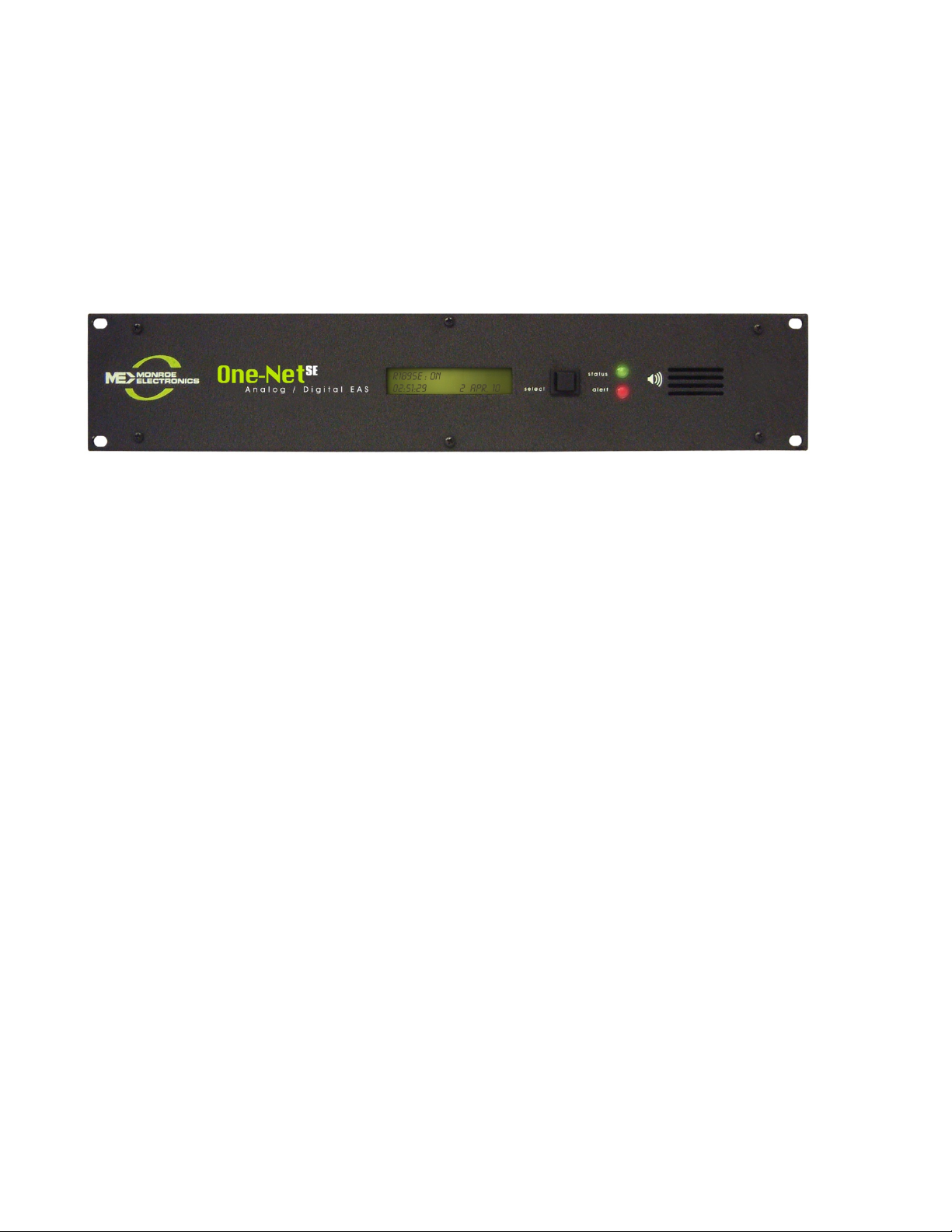
technology. It is an embedded PC platform. The front of the One-NetSE, pictured below,
provides a very simple face for a very sophisticated platform. The One-NetSE exposes the PC
motherboard connectors and single PCI slot in the rear of the unit.
2.2 Front Panel
The front panel features a 2x20 character backlit LCD that indicates power-on, and real-time
device status. There are also two LED’s - one red, one green - for indicating specific types of
status. The select switch provides the ability to activate a Required Weekly Test from the
front panel. A front panel speaker allows the user to verify the quality of audio signals.
2.2.1 LCD
The backlit green LCD provides real-time status of the One-NetSE. The LCD is used
for numerous purposes, all indicating system and/or encoding/ decoding and active
alert status. Here is a list of information available from the LCD.
When the One-NetSE is powered on, the LCD will light up, indicating power-on
state.
While the One-NetSE is booting, the LCD will move through a few display
states, eventually arriving at the ready state where the first line will display
One-Net: ON followed by a crawling display showing the programmed unit
name, the software version number and the IP address.
During decoding of an incoming alert, the LCD will display information about
the source and the stage of the decoding.
While decoded, forwarded or originated alerts are active on the One-NetSE, the top
line will repeat displaying pertinent identification for each active alert.
2.2.2 Status LED’s
The One-Net's two LED’s are used for a variety of status indications, making it easy
to see at a glance certain important system states.
- 4 -
Page 10

ouse
System Status - Green LED
When the One-NetSE is first powered on, the green LED is dark.
When the booting process advances far enough, the green LED begins to blink.
When the One-NetSE nears a ready state, the green LED blinks more rapidly.
When the One-NetSE is ready, the green LED light is on solid. A solid green
LED indicates the One-NetSE is operational.
If the green LED starts blinking, the One-NetSE server has become non-
operational. This can happen during software upgrades.
Alert status - Red LED
When the One-NetSE is first powered on, the red LED is dark.
After the One-NetSE becomes operational, in a ready state, with the green LED
solid, the red LED indicates decoding and alert sending status.
If the red LED is blinking quickly, with pauses, the One-NetSE server is
decoding an incoming alert. If the red LED is solid, the One-NetSE is sending an
EAS alert.
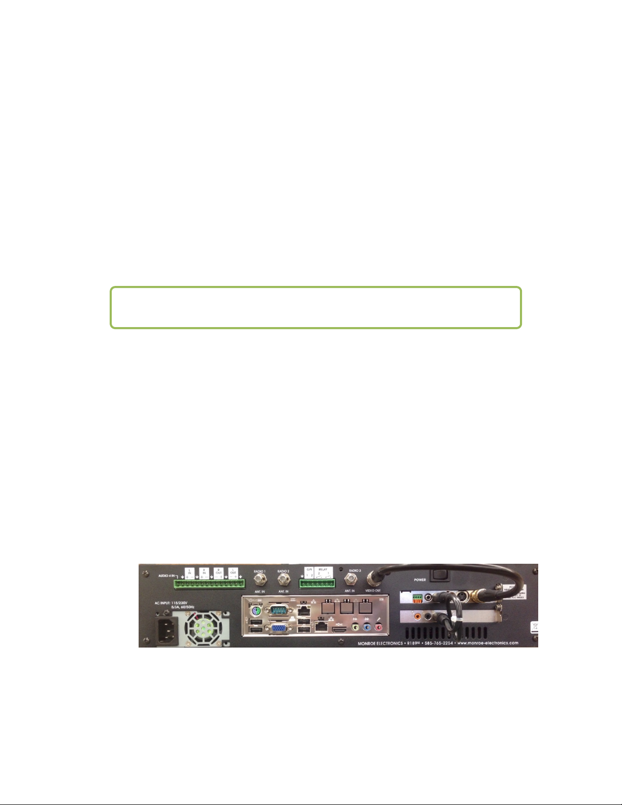
2.3 Back Panel Connectors
The back of the One-NetSE provides all of the connection ports. In addition to the standard
PS/2 mouse and keyboard and VGA monitor ports, the One-NetSE provides an RS-232 serial
port (COM1), two RJ45 LAN ports, four USB ports, main audio line in, out, and microphone
jacks, auxiliary audio line in, out, and microphone jacks, and a TV out connector.
EAS Audio
In
Analog Audio
Program in/out
Keyboard/
M
Serial
Port
2.4 Audio Wiring
Antennas
1, 2 & 3
VGA
USB
Ports
GPI
Contact
Closure
Main
Network
Port
HDMI
BNC
Video Out
EAS Audio
In
Networks
(Without 3-nic expansion)
EAS Audio
Out
EAS Audio
Expansion
Slot
In
Audio wiring on the One-NetSE has some flexibility due to the option of adding a second
sound card and because of built-in software control. Here are a few rules:
EAS decoder input always uses the audio line inputs.
Every line input can be used for decoding audio provided from an external receiver or
EAS decoder.
- 5 -
Page 11
Every line input supports two (2) EAS decoders. The left side of the input is decoded
separately from the right side. So two line inputs provide four (4) EAS decoders.
EAS alerts are selectively played out of the analog line output ports. Software is used to
select which ports are used for alert origination and forwarding.
The main microphone input is used to record EAS audio messages.
For decoding, each side of the stereo input of any audio input can be selectively used as a
single decoder source. In other words, one stereo input supports two EAS decoders. A dual
RCA to 3.5 mm jack input adapter can be used to connect two separate mono input signals to
a One-NetSE line input jack.
For alert encoding an audio cable is run from a software-selected 3.5 mm line output jack
into your systems alert audio wiring. Only analog audio output is supported.
NOTE: The SPDIF digital audio output port is not used.
2.5 Video Wiring
The video output provides an NTSC analog composite video signal through the yellow RCA
jack. This will provide a details page during alert forwarding and/or alert origination.
2.6 GPIO Output relays
The One-NetSE provides two General Purpose Output relays and two General Purpose inputs.
During an alert origination or forwarding, the GPO relay 1 is closed for the duration of the
alert audio portion of the alert, and GPO relay 2 can be programmed to close during the audio
or video portion of the alert.
2.7 MPEG Encoder Card Wiring
For One-Nets equipped with the optional MPEG2 Encoder card, see the illustration below for
wiring the MPEG2. The video output needs to be loop cabled back into the video input of the
Encoder card. Likewise, one audio output needs to be cabled to the MPEG audio input port.
Optional MPEG2 PCI Encoder Card Audio/Video connections
- 6 -
Page 12

E
3 One-NetSE Operation
3.1 Power Up, User Interface and Initial Setup
The One-NetSE uses a standard AC power cord. It uses a single power toggle switch to power
on.
NOTE: Power is supplied to the unit electronics while the external cord is
plugged and supplied with power even if the unit is powered off.
There are two ways to get a user interface are via a network connection using a Web browser
on a remote host. The One-NetSE is given a default static network address of 192.168.0.200.
The One-NetSE can be connected directly to another computer’s Ethernet port using a
network crossover cable, or can be connected to a hub or router using a standard network
cable. Network cabling may be done at any time.
NOTE: the One-Net
network connection.
S
must be fully booted before it can provide a
Once the One-NetSE is correctly cabled, power up by pressing the power switch or rocker on
the upper right corner of the rear panel. The LCD screen will light up if power is applied.
Allow the One-NetSE time to boot. The LCD screen and the green system status LED will
indicate when the One-NetSE is ready.
3.1.1 Directly connecting a networked host computer
Connect a CAT-5 network crossover cable, included with your One-NetSE, to the RJ45
port at the back of the One-NetSE and to the RJ45 port of the network interface card
(NIC) of a standalone PC or notebook computer. Configure the standalone PC to use the
static IP address 192.168.0.201 with a net mask of 255.255.0.0. After One-NetSE power
up and booting, it can be accessed via a Web browser on the host computer.
Now launch a Web browser application and direct the URL to http:/192.168.0.200/. The
One-NetSE will provide a gateway page and quickly redirect to the One-NetSE login page.
Follow the instructions for Section 3.2 below for logging into the One-NetSE using the
Web login page. After login, the One-NetSE is ready to use, although typically it will be
desirable to reconfigure the network address.
- 7 -
Page 13

3.1.2 LAN connection with a networked host computer
Connect a standard CAT-5 network cable from the RJ45 port at the back of the OneNetSE into a routing hub or other network-switching device. You will likely need
assistance from a network administrator to insure the One-Net’s default network address
of 192.168.0.200 will be visible on the network, or will not clash with an existing node.
Once the One-NetSE is powered up, booted, and operational, it can be accessed via a Web
browser from any remote computer on the LAN routed to see the address 192.168.0.200.
Follow the instructions for Section 4.2 below for logging into the One-NetSE using the
Web login page. After login, the One-NetSE is ready to use, although typically it will be
desirable to reconfigure the network address.
3.2 Web Server Login
When the One-NetSE successfully connects for a Web session, it will present the following
page in the Web browser.
Type "Admin" (no quotes) as the default user name, and "dasdec" (again, without quotes) as
the password. Press the left mouse button over the Login
and password, the One-NetSE will login. If the user or password is incorrect, the One-NetSE
will display a message indicating the problem. If the One-NetSE is left unattended for 10
minutes, it will automatically logout. A message indicating session timeout will be displayed
on the login screen.
At your first login, One-NetSE will show the Setup > Server page in your web browser.
Subsequent logins will start at the last page displayed prior to logout.
button. With the correct user name
One-NetSE Log in screen
- 8 -
Page 14
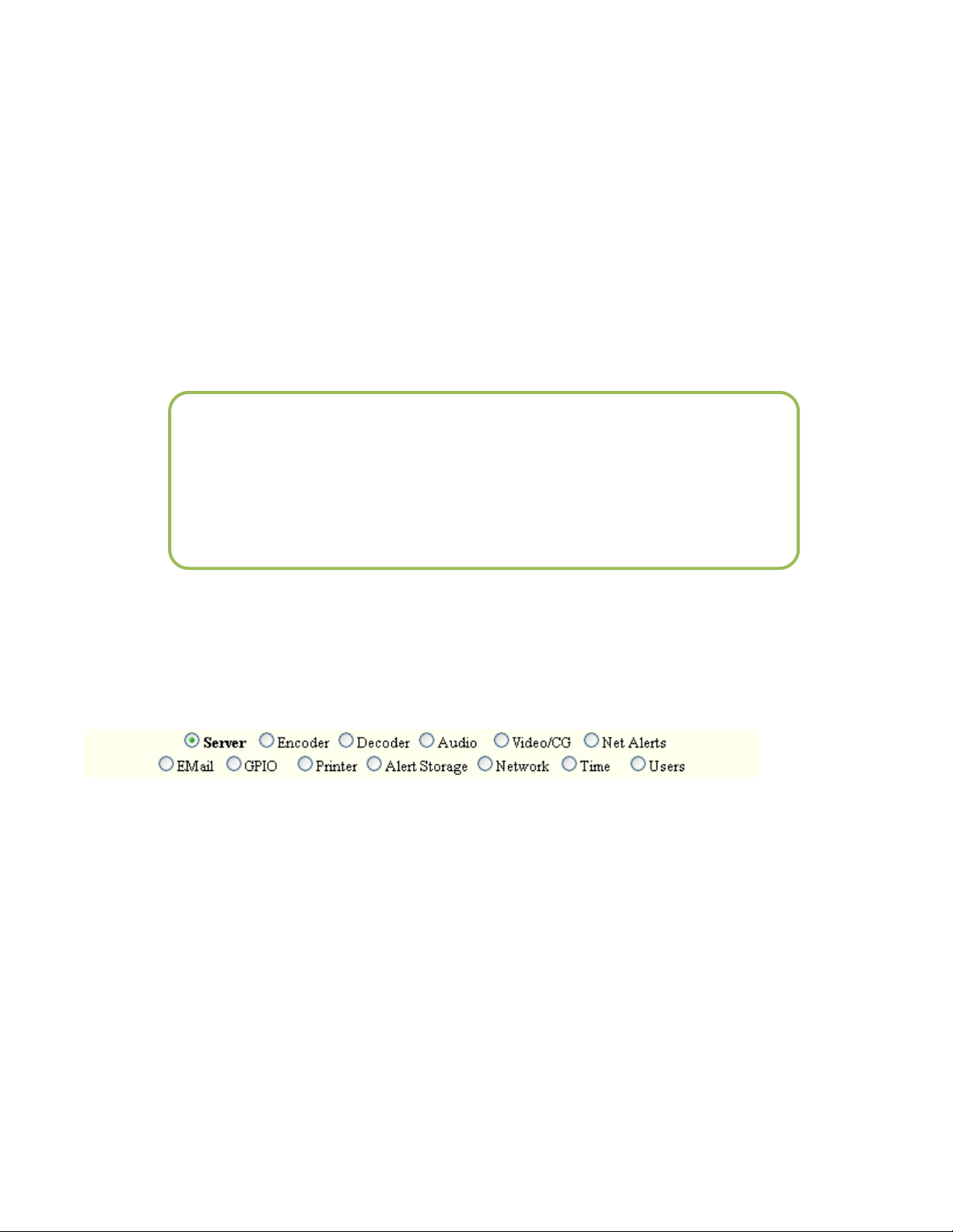
The One-NetSE Web Interface is organized as a rather standard hierarchical set of related
interfaces. Every page presents a standard header area with basic user session information
and a set of four (4) major tabbed page groups. The page groups are Encoder, Decoder,
Setup, and Server. For a decoder-only One-NetSE, the Encoder page group is omitted. Each
major group has a set of sub-options that appear as “radio” button selections under the group
tab (such as the Server sub-option page under Setup). Only one of these sub-options may be
selected at a time. Under a sub-option either a single page or another set of related tabbed
pages will be presented. To navigate the One-NetSE, first select the major group tab, and then
select the sub option under the tab. When moving from major group to major group, such as
from Setup to Server and back to Setup, the last selected sub option is remembered. To
refresh the current page, click on the “Refresh” button on either the top or bottom of the web
page.
IMPORTANT NOTE: In general, DO NOT use the back button or the
Refresh/Reload buttons on your browser to go back to pages visited
earlier. Although this often works, it can provide misleading, out-of date server state information, and in some cases can result in
unintended actions being performed. Instead, always use the provided
One-NetSE navigation buttons.
This manual will present descriptions and screen shots from each of these groups and suboptions.
4 SETUP
The SETUP pages present the One-NetSE server configuration sub-options. These are, in left to right
order:
At the first login, before the One-NetSE can be used, the server must be configured. The
recommended order is to first set up the Server, then Network, Time, Users, Email, Audio,
Video/CG, Decoder, Encoder. The subsequent chapters review information on the screens and
provide additional information.
4.1 Setup > Server: Server Configuration
If the web page displayed is not Setup > Server, select this page using the tab at the top of
the web page. There are three tabbed sections: Main License, Configuration Mgmt, Upgrade,
and Options.
- 9 -
Page 15
- 10 -
Page 16
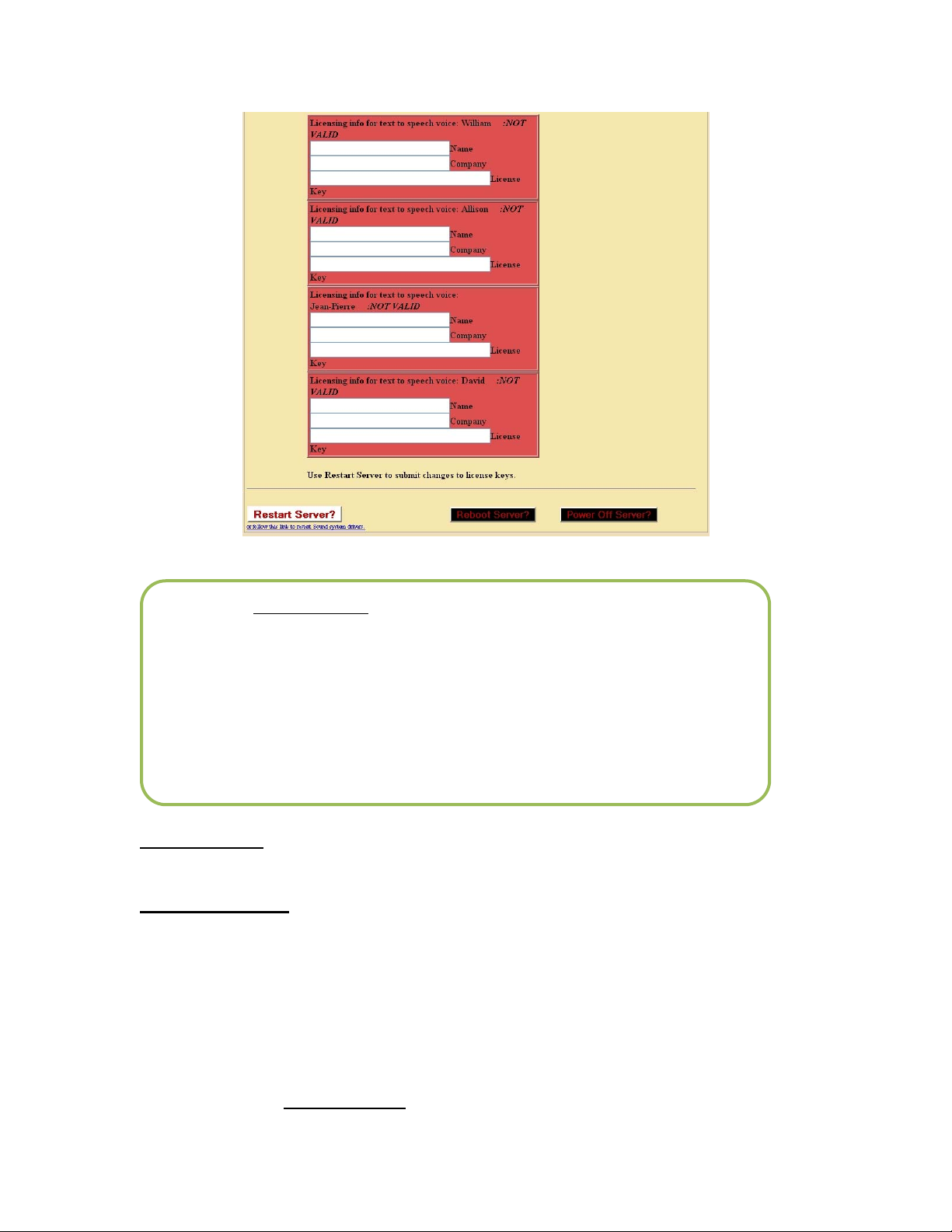
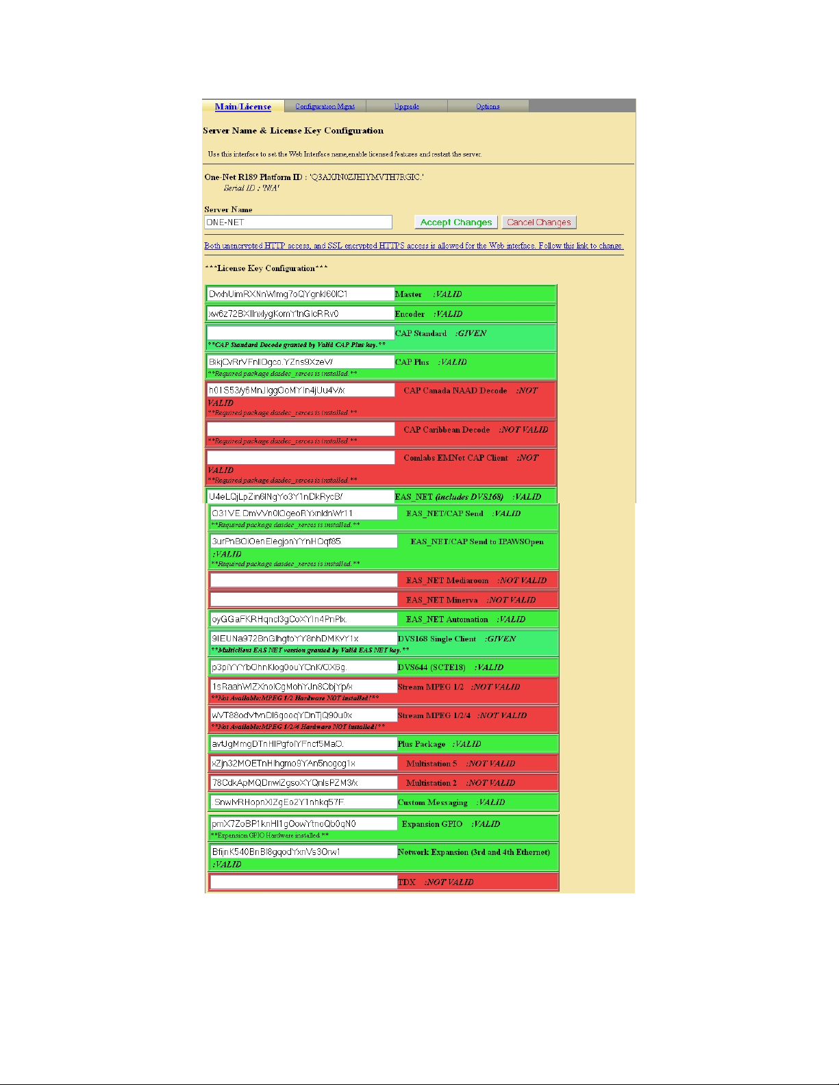
Setup > Server > Main/License: Web Page, License Key Configuration
NOTE: The Restart Server? Button on this page can be clicked to restart
the One-NetSE server software. This is used during License Key
configuration. It can also be used at any time the One-NetSE appears to
be functioning incorrectly. A confirmation page is displayed before the
restart is actually run. All logged in users will be forced out of the
system and will be required to log back in. Decoding will be temporarily
paused during the restart. This is not a system reboot, but nonetheless:
USE THIS OPTION WITH CARE!
Reboot Server?
the entire boot process when it starts back up.
Power Off Server?: This option powers down the One-Net.
: This option is a full system reboot. The unit will power down and go through
4.1.1 Main/License
One-Net ID
This is a unique identifier for the actual One-NetSE hardware. This is different for every
One-NetSE. It cannot be edited.
Server Name
The One-NetSE server name can be edited. If changes are made to this value, save them
by clicking Accept Changes.
- 11 -
Page 17

License Key Configuration
Master
The Master license key is preconfigured.
To enable any of the following options in the future, not originally purchased with
this unit, follow these steps:
Enter the key, obtained from Monroe Electronics, into the box to the left of the
option.
Click on the “Restart Server” button to enable the option.
After the Server restarts, Log back into the unit and the option you just entered
the key for should have changed from red to green indicating it has been
enabled.
Encoder
A second product key protects the Encoder functionality. Once a valid Encoder key
has been enabled, you can configure and use the One-NetSE encoder.
CAP Standard
Common Alerting Protocol (CAP) Software Option for One-Net directly handles
CAP v1.2 messages to ensure compliance with FEMA/IPAWS profile 1.0
requirement for text and audio processing.
CAP Plus
Common Alerting Protocol (CAP)-Plus Software Option for One-Net directly handles
all currently specified CAP v1.2 messages; (text, audio, images, etc.) as well as 2 full
years of in-version upgrades to ensure compliance with FEMA/IPAWS profile 1.0
requirements “ includes support for automatic Text-To-Speech translation of alert
text, and basic, single-voice, Text-to-Speech license.
CAP Canada NAAD Decode
This allows you to use the National Alert Aggregation & Dissemination System
(NAAD System) to decode National Alerts in Canada.
EAS_Net/CAP Send
This option is used in the IPTV market or if a One-NetSE is sending alert information
to another One-NetSE. This software addition allows you to be able to originate and
encode CAP alert messages.
EAS_NET/CAP Mediaroom
This software option adds support for Microsoft Mediaroom.
- 12 -
Page 18

EAS_Net Minerva
This option is used when the One-NetSE is communicating to Minerva middleware.
EAS_NET/CAP Automation
EAS NET support for Wide Orbit (broadcast automation software for television
stations, radio stations, cable television stations, cable operators, web television,
digital television and out-of-home advertising) and RCS Nexgen (provider of
scheduling and broadcast software for radio, Internet and television stations).
DVS168
This option unlocks EAS alert network forwarding via the SCTE DVS168 standard.
DVS644 (SCTE-18)
This option unlocks EAS alert network forwarding via the DVS644 (SCTE 18)
standard.
Stream MPEG 1/2
This option unlocks EAS alert encoding into an MPEG stream. This option can only
be enabled in units equipped with the MPEG-2 card hardware option.
Stream MPEG 1/2/4
This option unlocks EAS alert encoding into an MPEG stream. This option can only
be enabled in units equipped with the MPEG-4 card hardware option.
Custom Messaging
This option unlocks the Custom Messaging feature. When enabled a license must also
be provided for the voice for the text to voice feature.
Network Expansion
Triple Port Gigabit Ethernet Expansion option. This FACTORY INSTALLED option
adds three (3) 10/100/1000bT Ethernet ports for a total of four (4) unique Ethernet
network links (The standard One-Net Ethernet port remains 10/100bT). Please
contact the factory regarding upgrading in-field units.
TDX
This option unlocks the EAS Textual Data eXchange option. TDX allows extra
details to be encoded into alert messages.
Licensing info for text to speech voice: David, Allison, William, and Jean-Pierre
This package provides a free simple text to speech engine and a commercial licensed
advanced text to speech engine. This package is currently only used for the OneNet
Custom Messaging package. Later versions of OneNet software will support further
uses of Text to Speech. This package will be pre-installed on systems purchased after
Aug 15, 2008.
David voice: This package provides a realistic male voice for the Advanced
Text to Speech option. This voice must be separately licensed within the
- 13 -
Page 19

OneNet before it can be used. The current license key for the 6.2-1 speech
synthesis package is NOT compatible with the 2.0-0 packages. Licensing for
one voice is given with the Custom Messaging license. This package will be
pre-installed on systems purchased after Aug 15, 2008.
Allison voice: This package provides a very realistic female voice for the
Advanced Text to Speech option. This voice must be separately licensed
within the OneNet before it can be used. The current license key for the 6.2-1
speech synthesis package is NOT compatible with the 2.0-0 packages.
Licensing for one voice is given with the Custom Messaging license. This
package will be pre-installed on systems purchased after Aug 15, 2008.
William voice: This package provides a realistic male voice for the Advanced
Text to Speech option. This voice must be separately licensed within the
OneNet before it can be used. The current license key for the 6.2-1 speech
synthesis package is NOT compatible with the 2.0-0 packages. Licensing for
one voice is given with the Custom Messaging license. This package will be
pre-installed on systems purchased after Aug 15, 2008
Jean-Pierre: This package provides a realistic male French Canadian voice for
the Advanced Text to Speech option. This voice must be separately licensed
within the OneNet before it can be used. The current license key for the 6.2-1
speech synthesis package is NOT compatible with the 2.0-0 packages.
Licensing for one voice is given with the Custom Messaging license. This
package will be pre-installed on systems purchased after Aug 15, 2008
4.1.2 Configuration Mgmt
This page is used to backup or restore the configuration of your One-NetSE. A copy of the
configuration can be stored in another location and can even be uploaded into another
One-NetSE.
Make Backup
Clicking on this button will start the process of creating a configuration backup. This
backup will save all of your configuration settings, except for the Setup Network
page, to a file that will be stored in your One-NetSE. This file can be stored in another
location by clicking on “Download selected configuration file”. This configuration
file can be store in a safe place and can be used to restore your settings in the OneNetSE.
- 14 -
Page 20
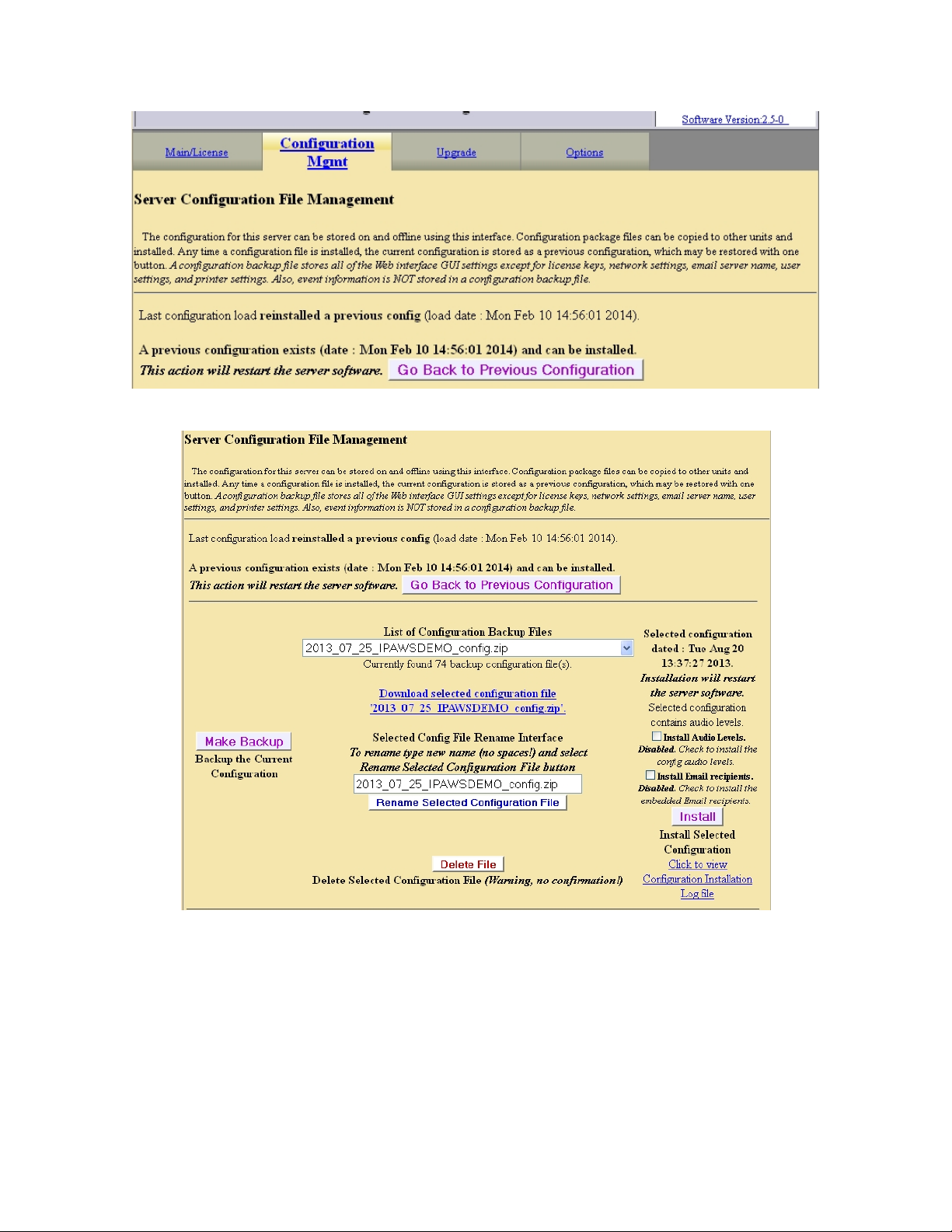
Setup > Server > Configuration Mgmt: Before clicking “Make Backup”
Setup > Server > Configuration Mgmt: After clicking “Make Backup”
- 15 -
Page 21
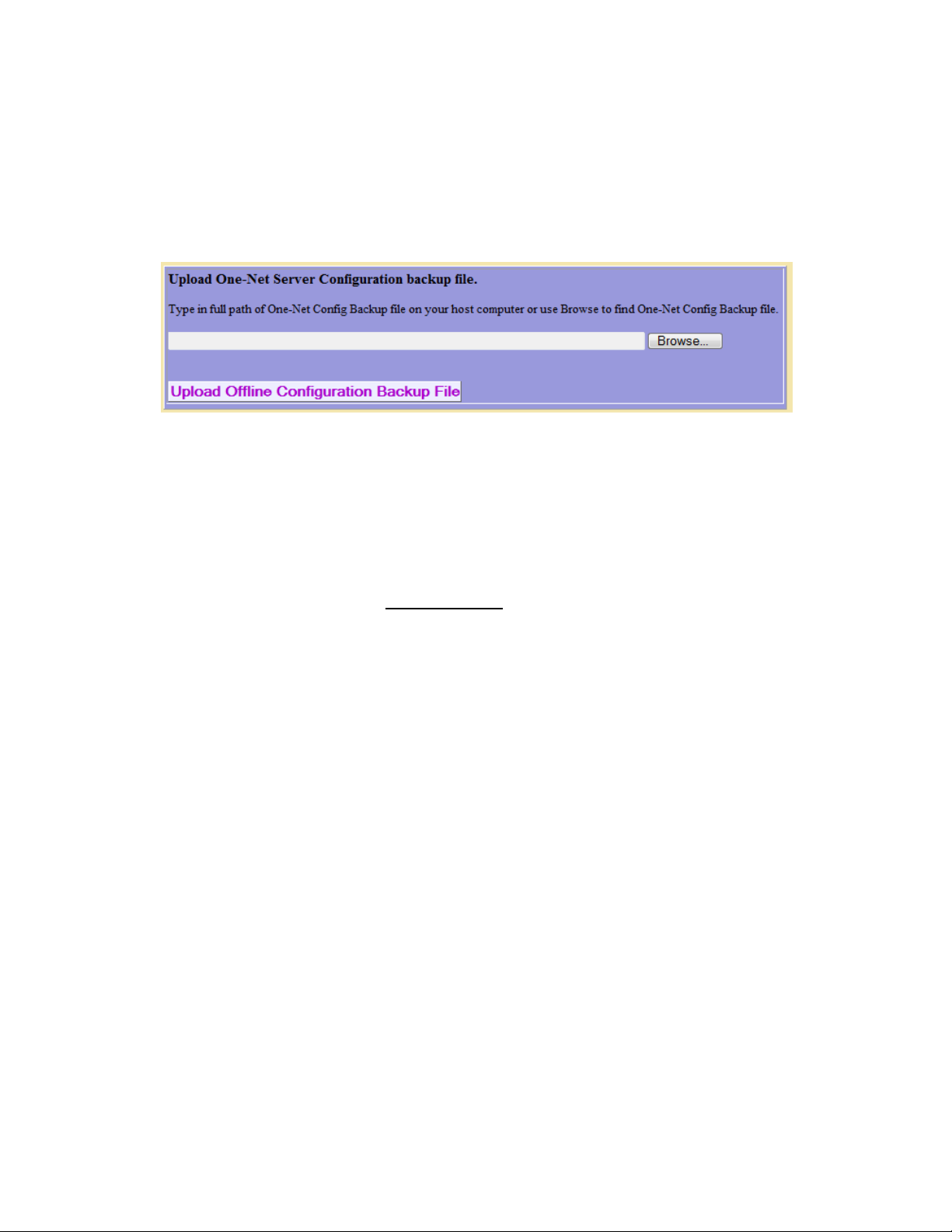
Upload Offline Configuration Backup file
Clicking on this button will allow you to start an upload of a previously stored
configuration file. This is useful if you want to configure multiple units with the same
configuration, and for restoring a configuration that has been changed.
Setup > Server > Configuration Mgmt: Upload Configuration Backup File
4.1.3 Upgrade
Upgrade One-NetSE Software
One-NetSE software can be conveniently upgraded through the Web interface with this
feature. One-NetSE upgrades are done using RPM files. The RPM file must be available
from or on your local host computers file system to use this feature. Type the path name
of the file into the text box, or browse your local computer’s file system until you locate
the RPM file. Then click Upgrade Server. A confirmation page will allow you to continue
with or cancel the upgrade. After accepting the upgrade, status will be returned about the
file if it is not a correct upgrade file. Otherwise, you will be logged off the One-NetSE
Web interface and will be directed to log back in after a short waiting period.
- 16 -
Page 22
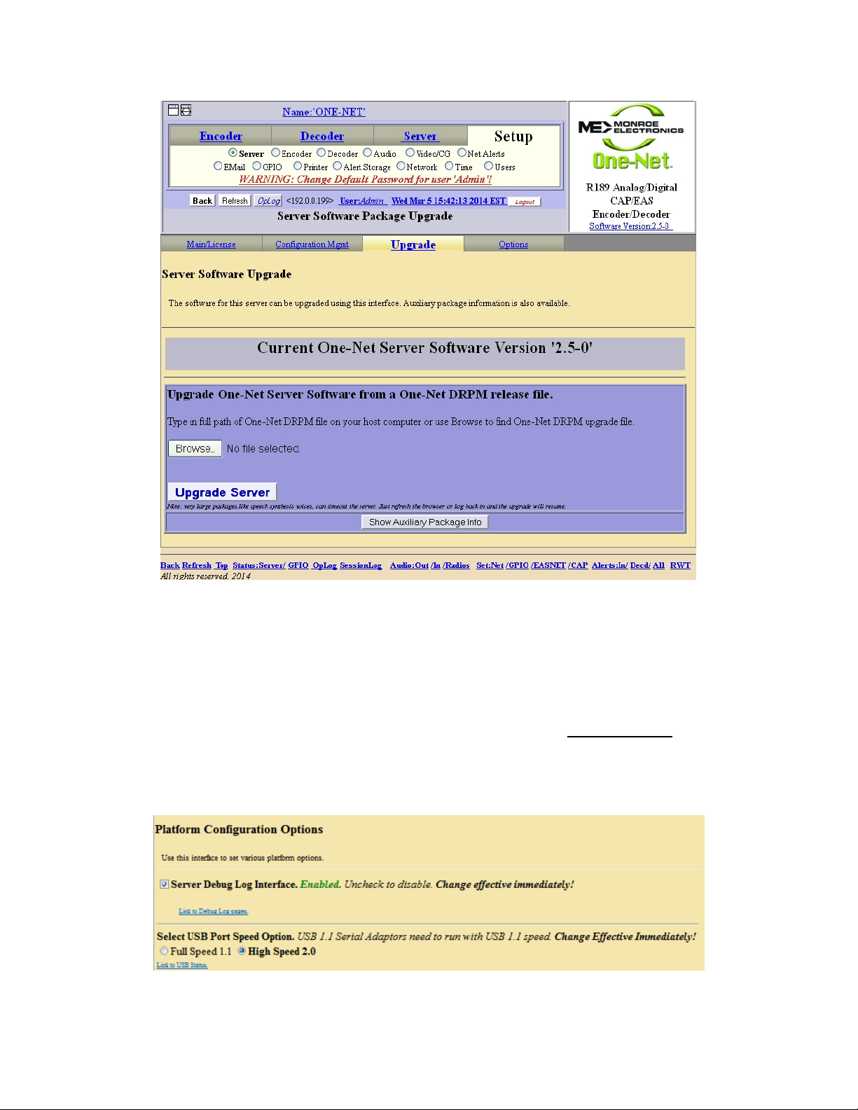
4.1.4 Options
Server Debug Log Interface: When enabled, this feature allows detailed debugging
output to be generated during One-Net operation and viewed from the Server >
Debuglogs pages. Check the toggle box to enable, or uncheck to disable. This option
should only be enabled during difficult troubleshooting or under the direction of DAS
customer support. The change is effective after use of the Restart Server
Select USB Port Speed Option: If your USB serial ports require a different speed, use
this option to change that.
Setup > Server > Upgrade
button.
Setup > Server > Options
- 17 -
Page 23
4.2 Setup > Network:
4.2.1 Configuration
Use this page to configure the One-NetSE to operate on a network(s), such as:
One-NetSE network address information
A static IP address; or
DHCP to automatically acquire an IP assignment
Set the Netmask, optional DNS (domain name services), and an optional gateway
value.
Add static routes.
Information on current network configuration is displayed on the bottom half of the page.
See the following sections for more information.
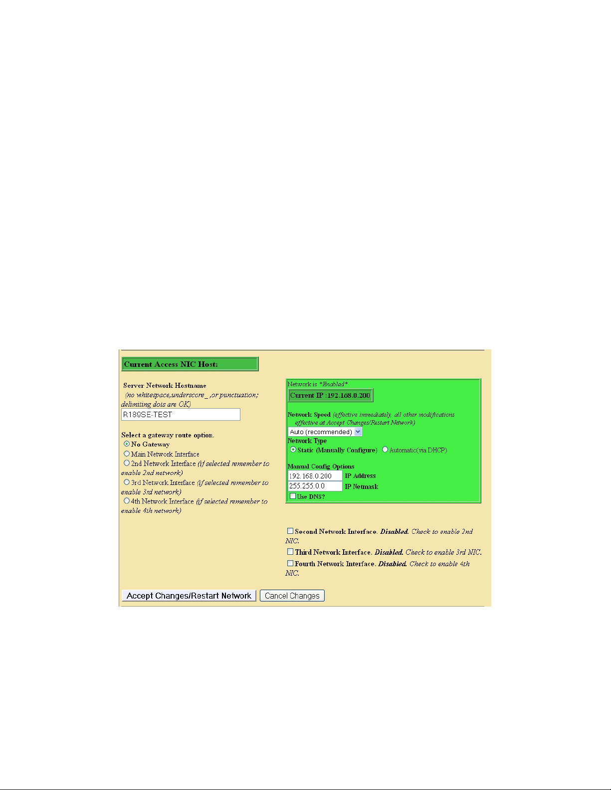
Network Type > Static: Default IP Address
When Network Type > Static is selected, the One-Net
address of 192.168.0.200 [Manual Config Options]. The default IP Netmask is
255.255.0.0. No default DNS or gateway is configured. The “Network Speed” (above the
Network Type) is recommended to be set to “Automatic”.
SE
by default is given a static IP
Setup > Network > Configuration: Static IP
- 18 -
Page 24
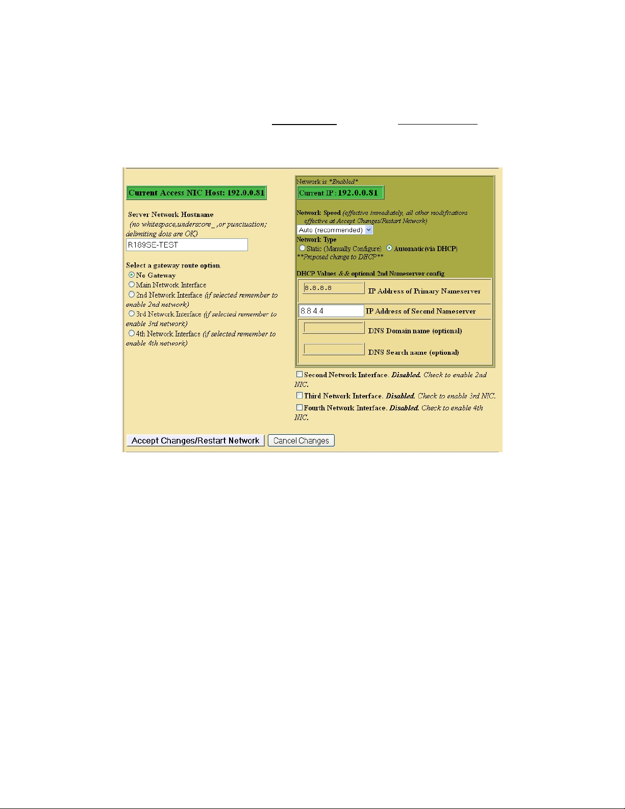
Network Type > Automatic: Set the IP address using DHCP
DHCP is a very convenient way to network a computer. It requires that your LAN be
running an accessible DHCP server. When DHCP is used, the IP address, the Netmask
and a DNS server are automatically granted. To use DHCP on the One-NetSE select
Network Type > Automatic (via DHCP). Then click Accept Changes. See the example
SE
below. Once the DHCP setting is accepted, the One-Net
will log you off. After a few
seconds wait, you can then log back in.
Setup > Network > Configuration: DHCP IP
- 19 -
Page 25
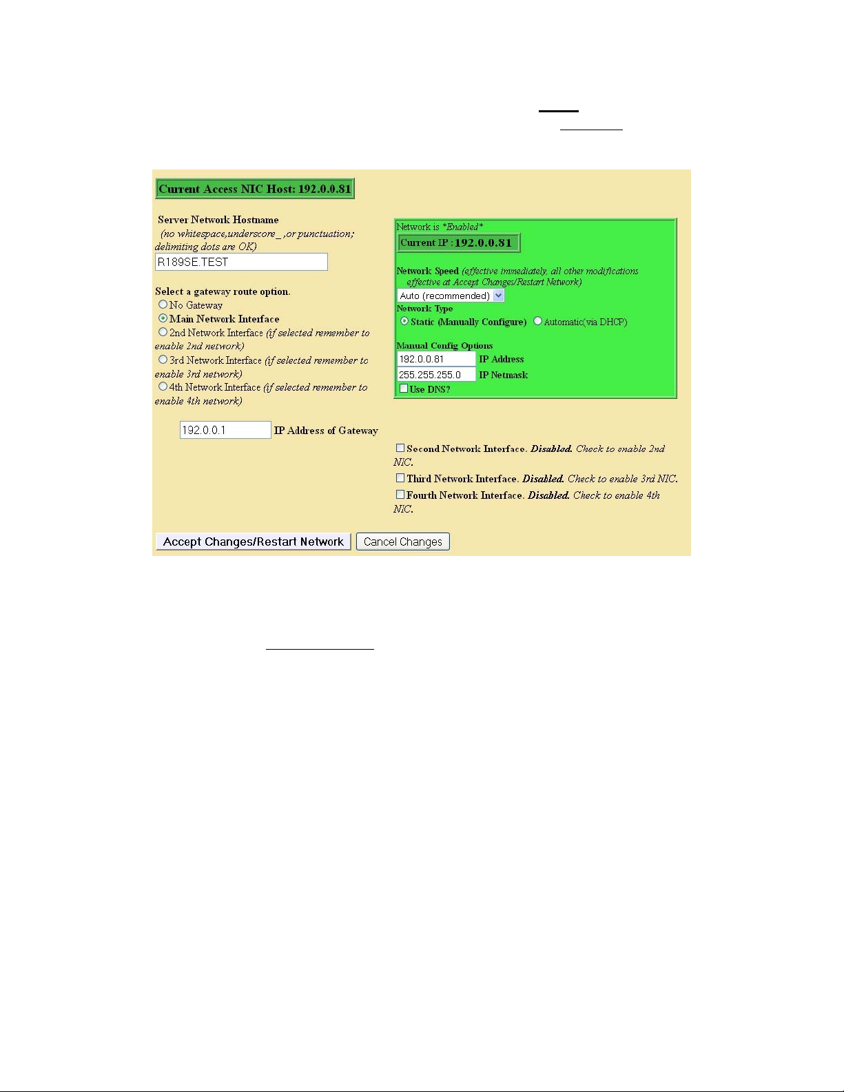
Network Type > Static: Setting the IP address manually
To set a new static IP address, select Network Type > Static. Then fill in the values for
the desired IP address and Netmask. If needed, also select Use DNS and/or check for
addition of a default gateway route.
Setup > Network > Configuration: Set-up Static IP manually
Enter the corresponding values. The example shows a new IP address of 192.0.0.81 and a
Netmask of 255.255.255.0, as well as a DNS and gateway configuration. To set the new
values, select Accept Changes.
SE
Once the new settings are accepted, the One-Net
will log you off. After a few seconds
wait, you can log back in on the redirected address on the Login page, as before.
IMPORTANT! You must be CAREFUL when configuring a static network address if
you are configuring from a remote host. If an address, which is inaccessible to your
network, is accepted for the One-Net
SE
, you will be unable to log back in from the remote
host. If this happens to you accidentally or on purpose, you will have to directly login to
the One-NetSE from a directly connected VGA monitor, keyboard and mouse. You can
SE
always configure the One-Net
from this direct connection.
- 20 -
Page 26
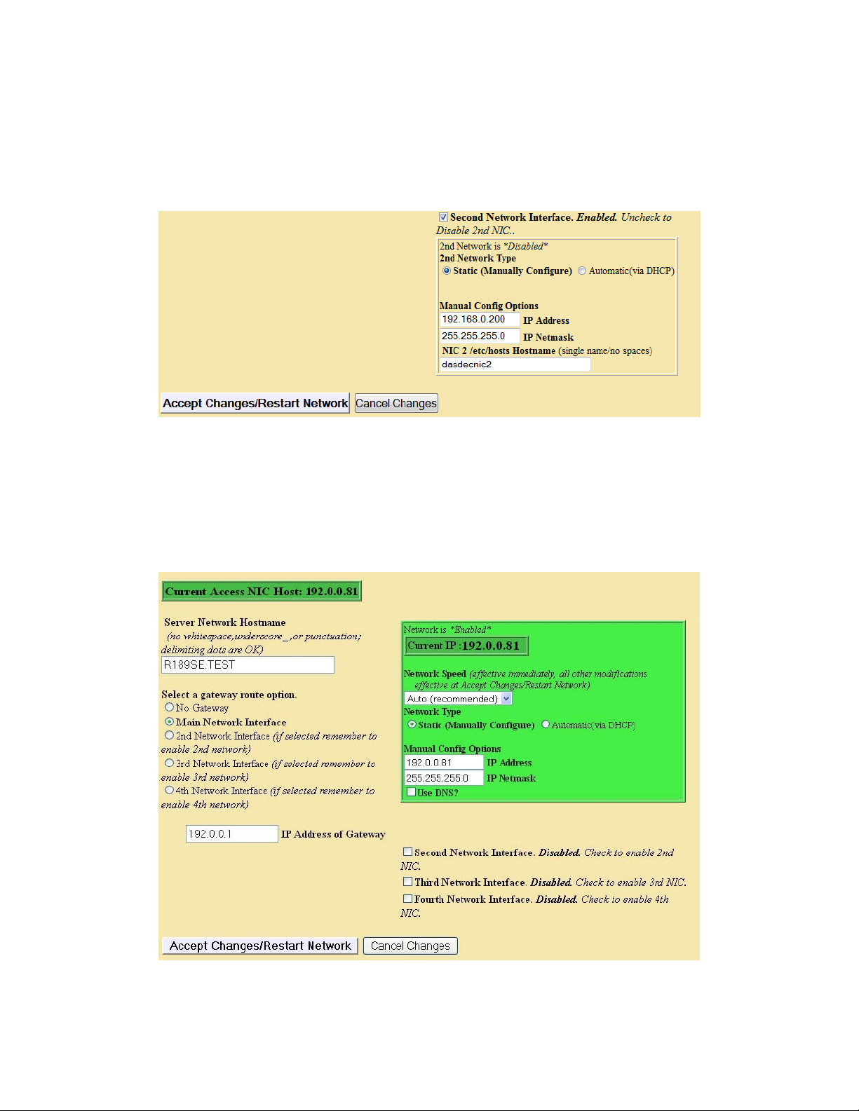
2nd Network
There is a 2nd network interface that comes standard with the One-NetSE. Programming
the 2nd NIC is done by first enabling the 2nd NIC by clicking on the box to the left of the
“Second Network Interface”. If an external NIC is seen by the One-NetSE, the setup box
will turn green. The setup boxes are exactly the same as the first NIC. A static address,
DHCP, and a gateway route can be used.
Setup > Network > Configuration: 2nd NIC
3rd and 4th Network
If the optional NIC daughter board was purchased with your One-NetSE, you will have
the ability to enable a 3rd and 4th network interface. The setup is the same as the first two
networks except for the fact that DHCP is not supported. A static IP address must be
used.
- 21 -
Page 27
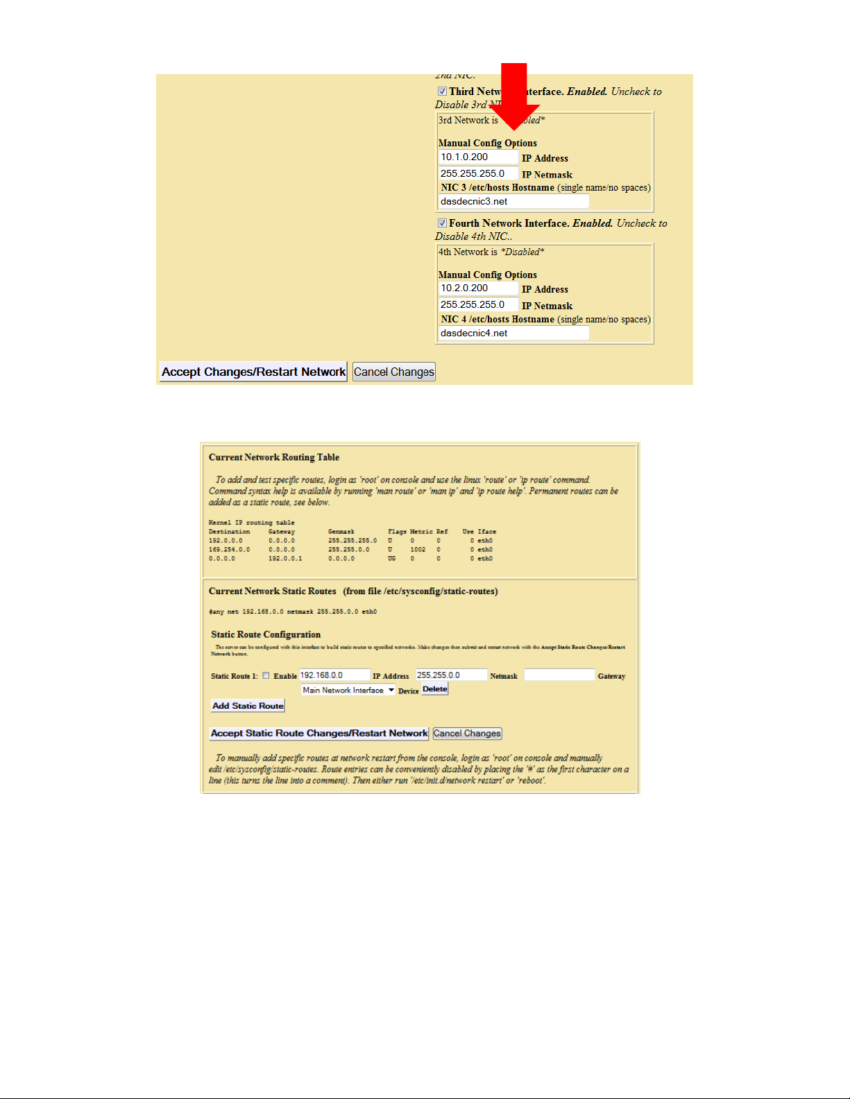
Setup > Network > Configuration: 3rd and 4th NIC option
Setup > Network > Configuration: Current Network Routing Table
Network Status Information
- 22 -
Page 28
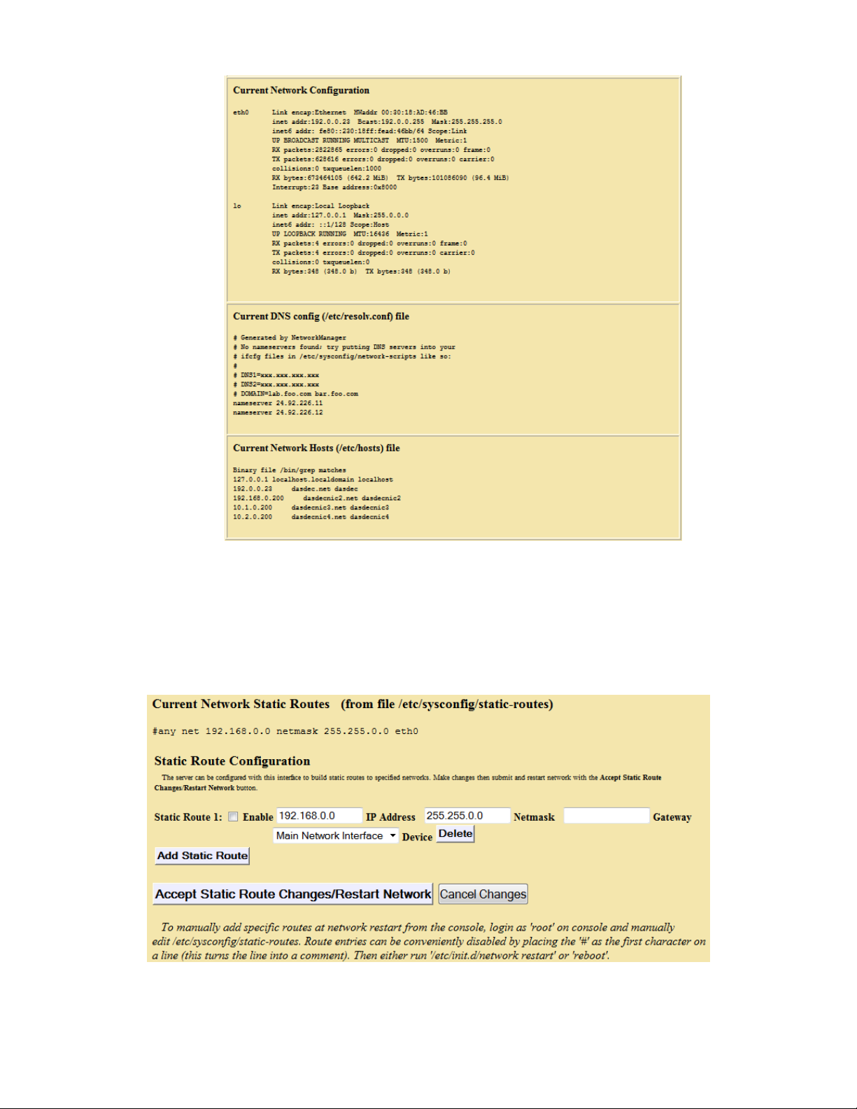
Setup > Network > Configuration: Current Network Configuration
Tables at the bottom of the Setup Network page show the current network routes and
network address information.
Static Route Configuration
The Main NIC 2nd, 3rd, and 4th NIC’s can be configured to use static routes. The IP
address, subnet mask and gateway setting can be programmed for each route.
Setup > Network > Configuration: Current Network Static Routes
- 23 -
Page 29
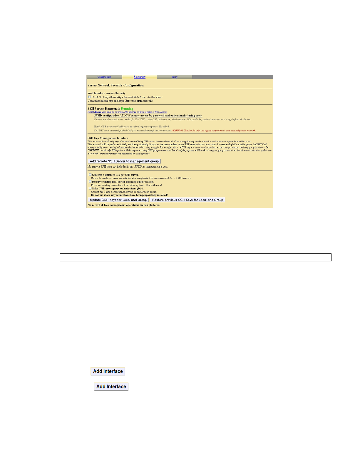
4.2.2 Security
The One-NetSE can be configured to allow unencrypted HTTP access or only SSL
encrypted HTTPS access. By placing a check mark in the box only SSL encrypted
HTTPS access will be allowed.
Setup > Network > Security
SSH Key Management Interface
WARNING: DO NOT MODIFY any SSH Keys without consulting with the factory!
Secure Shell is used for EAS NET network communication/control between a DASDEC II and other EAS NET
compatible platforms (including other DASDEC II's). SSH is a secure communications method that relies on
public/private key encryption. For a DASDEC II to communicate with another platform via SSH, the public key
from the DASDEC II's public/private key pair must be "authorized" on the remote platform.
Authorization usually is achieved by copying the public key into a file on the remote host. The DASDEC II uses
the open source package OpenSSH for SSH features. This package has a file called "authorized_keys2" under
/root/.ssh/ to hold the authorized public keys from remote platforms. Authorization allows secure access only
from the holder of the public key's corresponding private key. Even though this method of encr yption and secure
access is very safe, it is still as a good idea to update the public/private keys from time to time. This can be
tedious to do manually between a set of servers that already intercommunicate. The DASDEC II SSH Key
Management interface greatly simplifies this process. It allows a group of remote hosts offering SSH connections
to have all of the encryption keys updated from the current DASDEC II location. This updates and maintains
secure SSH based network interoperability for EAS NET across each platform with a single operation.
To use this interface correctly, you must add client interface descriptors for each remote platform in the managed
group. The button is used to create each descriptor. When a descriptor is added using this button,
there is no need to confirm the addition. The screen shot below shows a single remote client descriptor that was
added using . Add as many as descriptors as needed. (EAS NET allows up to 8 connections.)
- 24 -
Page 30
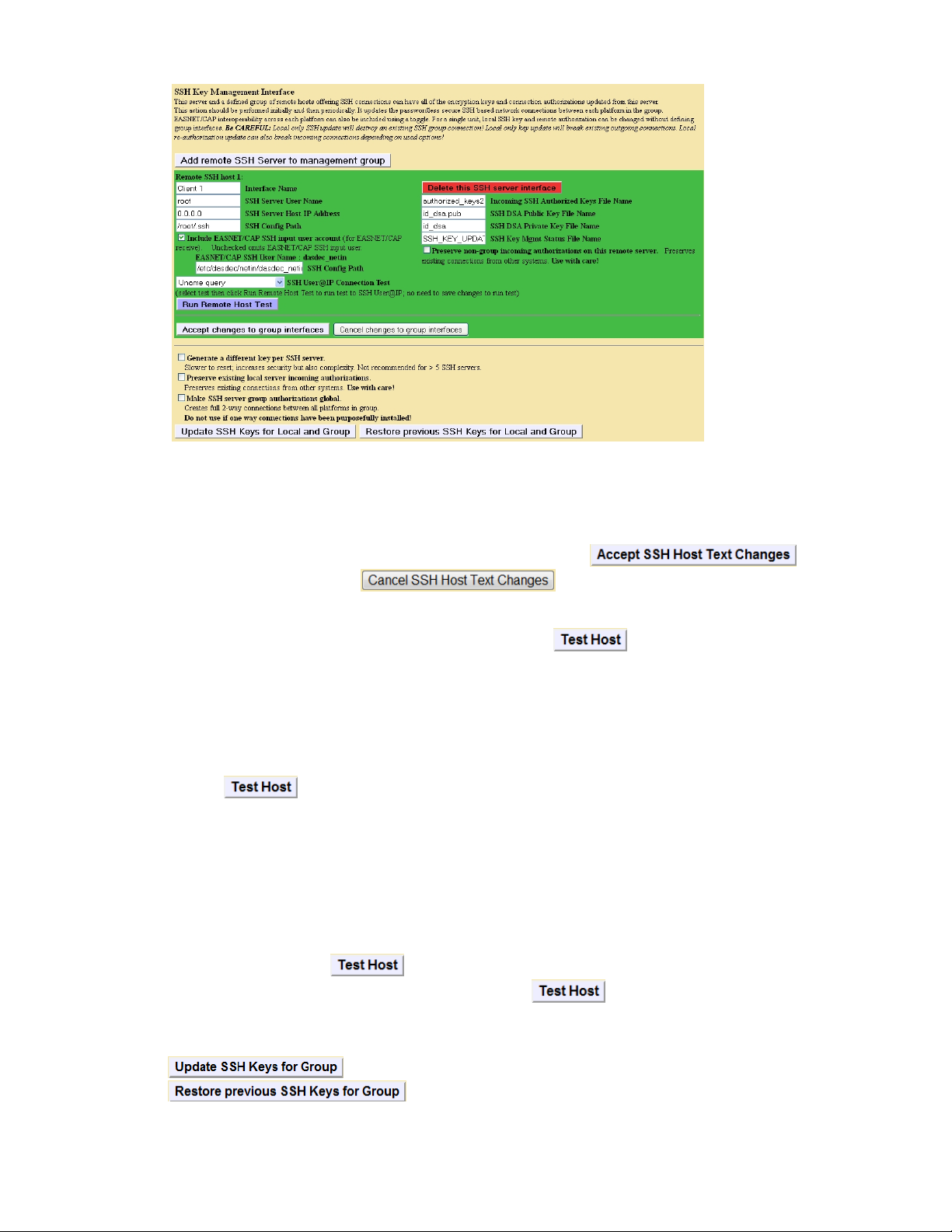
SSH Key Management Interface
Once a remote host client descriptor interface is added, it must be configured. Reasonable default values for
SSH connection to the remote host are provided (except for IP address). Type in the IP Address and change the
remote host User name, the SSH configuration path (directory), the SSH authorized keys file name, DSA public
key and private key file names, and management status file name if needed.
Changes to these Host text field values are not saved until you click . You can
cancel changes by clicking the button.
A very useful feature of this interface is that it provides network connection tests to remote hosts. Set the selector
SSH Connection Test to the desired test and click the button .
You can try a variety of tests to prove SSH connectivity as well as network connectivity via "ping". Six tests are
supported:
1. "Ping". Use a simple network ping to test if the base network route to a remote host exists. To test
basic network connectivity, the ping test can be used without regard to the SSH field configuration.
Set the IP address (numeric dot.decimal format unless DNS is enabled) and run the Ping test using the
button.
2. "Uname" query via SSH (see example above). This will attempt to get the operating system name from
the remote host.
3. "Date" query via SSH. This will attempt to get the date and time from the remote host.
4. SCP test via SSH. This will attempt to copy a test file to the remote host.
5. "Key Management Status" query via SSH. This will attempt to retrieve the current state of the DASDEC
II key management status from the remote host.
6. "Get Public Key" query via SSH. This will attempt to retrieve the public key from the remote host.
Select a test and click the button to see the test results. Be patient; it can take several seconds to
run some of these tests. Results are printed just below the button.
When you have all of the remote host descriptors entered properly, and you have confirmed SSH connectivity to
each remote host, you may safely update the public/private keys for the entire group by clicking on the button
. You may also return to the prior set of keys by clicking the button
.
- 25 -
Page 31

The status of the last group management operation is printed just below the button.
This gives a date and useful information about the last SSH management operation performed from this
DASDEC II.
The page display areas below the SSH Management interface provide two more useful pieces of information
about SSH. The first display shows the current SSH DSA Public Encryption Key and its installation date. Belo w
this is a printout of the "authorized keys" file. This shows remote hosts authorized for SSH connections to this
DASDEC II.
4.2.3 Proxy
Current Optional HTTP/HTTPS Proxy server assignments for getting CAP data
The server can be optionally configured to access remote http and/or https data (for CAP
data) via a defined proxy server address. Enter the hostname:port in the appropriate field
below. Make changes then submit with Accept Proxy Changes button.
Setup > Network > Proxy
4.3 Setup > Time: One-NetSE Clock and NTP
The Setup Time page allows the hardware clock on the One-NetSE to be set. Date, time, and
time zone may be set.
- 26 -
Page 32

Setup > Time
One-NetSE Date and Time Configuration
Make changes to date and/or time and/or time zone, and then click Submit changes. If Time
zone is changed, the One-NetSE will restart and you will be forced to log back into the Web
interface. If the time is set forward far enough, you will also be forced to log back into the
One-NetSE Web interface.
Network Time Protocol (NTP) Configuration
The One-NetSE supports Network Time Protocol (NTP) to synchronize its clock to another
clock over a network. This will synchronize the One-NetSE to an atomic clock over the
Internet, or to another computer running NTP on your LAN, or to another One-NetSE running
as an NTP server on your LAN.
NTP Server name or IP Address:
SE
You must enter a name of a remote NTP server that is accessible from the One-Net
LAN.
Public NTP servers can be viewed by following the link provided.
NOTE: The computer hosting the Web browser must have Internet access
to follow this link, and the One-NetSE must be able to contact the chosen
NTP server.
- 27 -
Page 33

The checkbox for NTP must be checked to start NTP. If no NTP server name is entered and
NTP is enabled, then the One-NetSE will become an NTP server that can be pointed at from
other One-Nets over the LAN.
4.4 Setup > Users
SE
The Setup Users page can be used to manage user accounts on the One-Net
. From this
page, you can add and delete user accounts, change the Web Interface passwords, and set
user permission levels. The Admin account cannot be deleted, and only Admin can change
the Admin password.
Edit One-NetSE User Account Profile
Select account pull down. Select the user account to edit from this list. Under this menu
is information about the selected user’s current and last login information.
Permission Level. A permission level can be granted (for non-Admin users) as View
Only, Basic Operation, Operation, Operation/Control, and Administration with this pull
down menu. Pages in the One-Net
SE
are granted a permission level for entry/access. For
instance, only a user with Administration permission may access the Setup > Users page.
Trying to access a One-NetSE page without the proper permission level will result in a
clear notification message.
Account Comment. A simple text comment can be attached to non-Admin user
accounts.
Change Password. Enter the current password, then enter the new password twice in the
fields provided. Only Admin can change the Admin password.
For these changes click Submit Changes. The changes are effective immediately.
Delete User. Non-Admin users can be deleted with this button.
NOTE: This is effective immediately
SE
Add New One-Net
User Account Type
Enter information as directed on the screen and click Create User.
- 28 -
Page 34

Setup > Users
Session Idle Timeout
The amount of idle time before being logged out of the One-NetSE is programmable. The
default setting is 10 minutes.
Show User Permission Levels Help
Placing a check mark in this box will show the user the help screen for permission levels.
This describes what settings/feature is available at each permission level.
- 29 -
Page 35
4.5 Setup > Email
The One-NetSE can be configured to optionally send email upon alert decoding, origination,
and forwarding. Select the Setup > Email page to configure an outgoing email server and to
configure the send options. There are four tabbed sections: Email Server, Event Email,
Decoder Email, and Encoder Email.
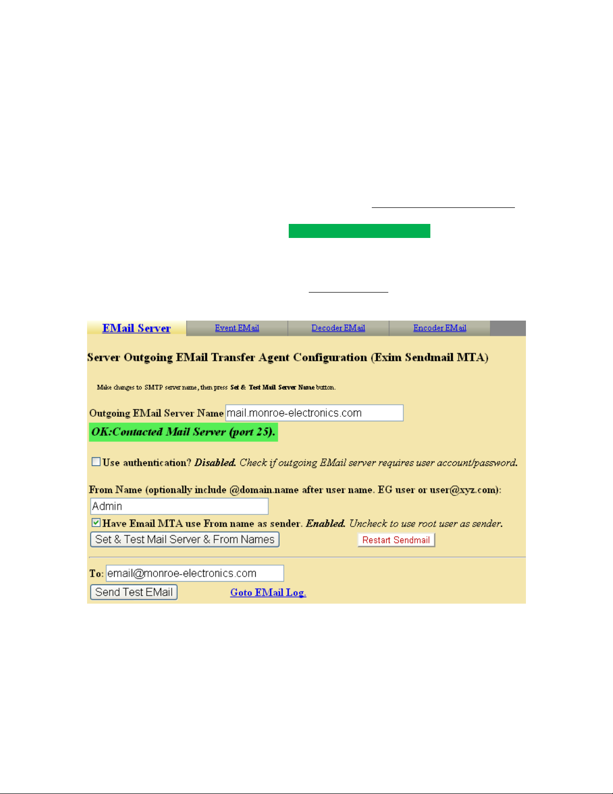
4.5.1 Email Server
To set the outgoing email server name without using authentication (port 25):
Select Setup Email >Email Server. From this page you can set the name of the
SMTP server for outgoing Emails from the One-NetSE. Enter a name in the text
field after Outgoing Email Server and click Set & Test Mail Server Name.
The One-NetSE will attempt to contact this Email server.
If it succeeds, the message "OK: Contacted Email Server" will display under the
name.
To test if Email can actually be sent via the chosen Email server, type a valid Email
address in the To: text field and click Send Test Email. If this works, the chosen recipient
should receive an Email.
Setup > Email > Email Server: Not using authentication
To set the outgoing email server name using authentication (port 587):
Select Setup Email >Email Server. From this page you can set the name of the
SE
SMTP server for outgoing Emails from the One-Net
.
Enable the Use Authentication? Option.
Provide a username and password for authentication.
- 30 -
Page 36

Enter a name in the text field after Outgoing Email Server and click Set & Test
Mail Server Name.
The One-NetSE will attempt to contact this Email server.
If it succeeds, the message "OK: Contacted Email Server" will display under the
name.
To test if Email can actually be sent via the chosen Email server, type a valid Email
address in the To: text field and click Send Test Email. If this works, the chosen recipient
should receive an Email.
Setup > Email > Email Server: Using authentication
4.5.2 Event Email
This page allows the user to the ability to have Event logs emailed either weekly or
monthly, and to be emailed when a successfully or failed login to the One-NetSE has
occurred.
Emailing EAS Event Reports
Check either of the boxes to disable or enable Emailing of Event Reports either on a
monthly or weekly basis. If enabled, enter the Email address in the Email To: field.
Server Access Reports
Check either of the boxes to disable or enable Emailing of Server Access Reports. If
enabled, enter the Email address in the Email To: field.
- 31 -
Page 37

4.5.3 Decoder Email
To set up the outgoing email for the One-NetSE decoder events, select Setup Email >
Decoder Email. Email can be sent upon alert decoding and/or forwarding. The Email
Server is identified. If changes to the outgoing email server are needed, return to the
Setup Email >Email Server screen.
Check the appropriate toggle and add email addresses to the Email To: field. Check
either:
Setup > Email > Event Email
- 32 -
Page 38

Setup > Email > Decoder Email
Email upon Alert Decoding: Check the box to disable or enable Email on Alert
Decoding. If enabled, enter the Email address in the Email To: field.
Email upon Alert Forwarding: Check the box to disable or enable Email upon Alert
Forwarding. If enabled, enter the Email address in the Email To: field.
Click Accept Changes.
4.5.4 Encoder Email
To setup the outgoing email for the One-NetSE encoder events, select Setup Email >
Encoder Email. Email can be sent upon alert origination. Follow screen instructions or
the same method described above for Decoder Email. Click Accept Changes for any
changes to be effective.
Setup > Email > Encoder Email
4.6 Setup > Audio: Audio Levels and Tone Testing
There are four audio screens to configure: Decoder Audio, Encoder Audio, Audio Output
Levels/Tests, and Radio Tuners. Start with Audio Output Levels/Tests.
- 33 -
Page 39

4.6.1 Output Levels/Tests
The audio output levels for the One-NetSE are always configured from this page. Also,
audio tones can be played through each available audio output in order to test the output
and calibrate levels using audio test equipment. Every One-NetSE will show the
configuration interface for the Front Panel Speaker, Main Audio and for the Auxiliary
Audio 1. Configure the levels by entering numbers from 0 to 100 for any specific port.
Values near 70 are a good starting point for the One-NetSE.
- 34 -
Page 40
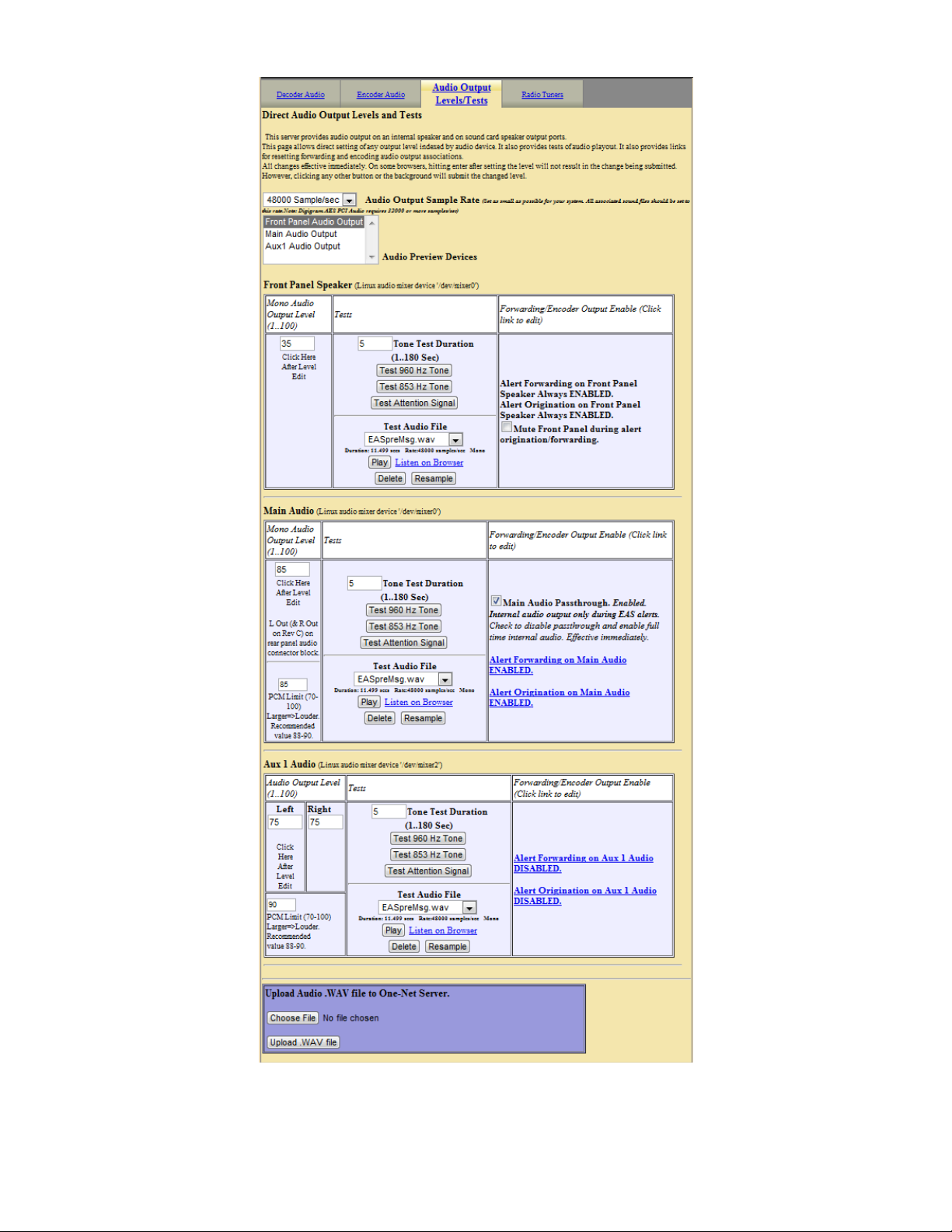
Setup > Audio > Audio Output Levels/Tests
- 35 -
Page 41

NOTE: The interface pages for Decoder and Encoder Audio display
and reference audio output levels for certain features. These references
always provide an active hyperlink into this page to allow for changes
to audio output levels.
To test the Main and/or Auxiliary Audio outputs, attach speakers to the One-NetSE audio
device output ports and run the various tone test buttons. The Front Panel Speaker can be
tested as is. These tests allow the One-NetSE to play each of the two single tones that
comprise the dual-tone EAS Attention Signal. The EAS Attention signal and WAV files
can also be played. The duration of the test is set per Audio device by the Test Tone
Duration fields.
Audio tests, audio levels and duration changes occur immediately.
Alert Audio Toggles
The Main and Auxiliary Audio displays also display with an active hyperlink if alert
audio from originated and forwarded alerts is enabled. Clicking these links will jump to
the correct Decoder and Encoder Audio setup page for changes to be made.
Upload Audio .WAV file to One-NetSE Server
This interface allows Wav files to be uploaded into the One-NetSE. Uploaded audio files
are available for tests as well as for encoding and manual forwarding.
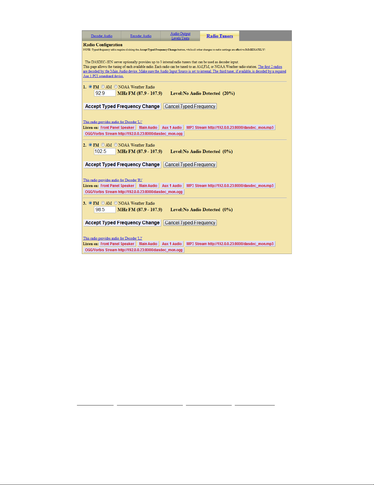
4.6.2 Radio Tuners
The One-NetSE can be equipped with up to three internal radio tuners. Each tuner can be
configured by the user, through the browser page, to receive AM, FM or NOAA stations.
Setting the Radio Types and Frequencies:
Use this screen to program the installed radios. For each radio select the radio type by
clicking on the button to the left of each type. Next, click on the frequency box and type
in the desired frequency for an approved radio station and click on the Accept Typed
Frequency Change button to accept the change. This frequency MUST correspond to an
approved LP1 or LP2 for your area. You can obtain a list of approved stations from the
EAS Chairman of your state. Repeat this process for all of the installed radios.
After setting all of the radios, verify that level is OK. This is displayed to the right of the
frequency box. To listen to the radio signal, you can select where to route the signal to
clicking on the appropriate button. In most cases the audio is routed to the front panel
speaker. Make sure to turn off the feature when done testing.
- 36 -
Page 42
4.6.3 Decoder Audio
There are three features provided to configure decoder audio: Alert Decoding, Decoder
Audio Monitoring, and Alert Forwarding.
Each One-NetSE EAS decoder channel can be independently tuned for input sensitivity,
and also can be enabled and disabled with the provided interfaces. The audio devices
used during alert forwarding are also configured from this screen.
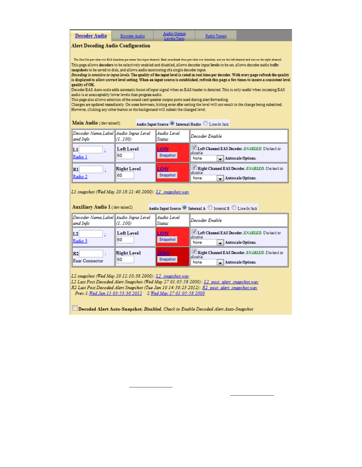
Alert Decoding Audio Configuration
Alert decoding occurs from active analysis of the audio input source on the Main and
Auxiliary audio devices. Each stereo input to an audio device allows for two EAS
decoder channels. Therefore the One-NetSE provides four decoders. Under the Alert
Decoding Audio Configuration section, each audio device available for the One-NetSE
is shown with a table that displays:
Decoder Name Audio Input Level (1..100) Audio Level Status Decoder Enable
Setup > Audio > Radio Tuner
- 37 -
Page 43

Under each of these columns is displayed information/controls per decoder. The Decoder
labels, shown for the Main Audio as LP1 and LP2, can be changed by the user if desired.
The interface allows the audio input level and the decoder enable/disable to be changed
per decoder. Changes become effective immediately. The Audio Level Status is a very
useful tool to test for correct audio input levels. It will display if an audio signal is too
low or high or OK. It can also detect if an audio input is silent. The level status is updated
each time this page is redisplayed or when audio changes are submitted. Set audio input
levels until the Green OK level is achieved.
Snapshot
Clicking on any of the four “Snapshot” buttons will create an audio .wav file for that
specific decoder. This file contains the last three minutes of audio detected by the
decoder. You can click on the link below the decoder to play the file. Snapshot is mainly
used for troubleshooting purposes.
Placing a check mark in the “Decoded Alert Auto-Snapshot” box will create a .wav file
every time an alert is decoded. This feature is also used mainly for troubleshooting
purposes.
EAS Auto-scale
Placing a check mark in the “EAS Auto-scale” box will allow the One-NetSE to
automatically adjust the audio level to a decoder if the level is too high or too low. This
feature is used if signal levels from a source are not stable.
- 38 -
Page 44
Decoder Audio Monitoring Configuration
These two interfaces allow a One-Net
input. The Select Decoder Audio to Monitor list presents all of the decoder audio
channels available to hear. The Decoder Audio Monitor Output list allows a specific
output port to be selected to hear the audio chosen in Select Decoder Audio to Monitor.
Choose a decoder channel and select an output port that has speakers (or the Internal
Speaker) and click Accept Change
decoder and/or the None Audio output and again click Accept Change
Alert Forwarding Audio Configuration
After the One-NetSE decodes an EAS alert, it can be configured to “Forward” the alert.
That is, it can play the alert as audio over a selected audio output. This interface allows
Setup > Audio > Decoder Audio
SE
user to hear the audio from a selected decoder
s. To disable audio monitoring, select the None
- 39 -
s.
Page 45

for enabling Forwarding audio on each of the audio output devices. Enabling/disabling is
achieved using the provided checkbox toggles. The text next to the toggles clearly
indicates the current state and the result of toggling. The audio output levels are also
displayed and provide an active hyperlink to the Audio Output Levels/Tests page to
change the output levels. Changes do not take place until Accept Changes is clicked.
Setup > Audio > Decoder Audio: Decoder Audio Monitoring Configuration
4.6.4 Encoder Audio
There are two main configuration options for encoder audio: Alert Encoding and
Microphone selection.
- 40 -
Page 46

Alert Encoding Audio Configuration
When the One-NetSE encoder is used to originate an EAS alert, the audio associated with
the alert must be played out of an output port in order for the alert to be transmitted or
decoded by another decoder. The audio for the alert must be configured to play over a
selected audio output. This interface allows for enabling/disabling Originating audio
on each of the audio output devices. Enabling/disabling is achieved using the
provided checkbox toggles. The text next to the toggles clearly indicates the current
state and the result of toggling. The audio output levels are also displayed and provide an
active hyperlink to the Audio Output Levels/Tests page to change the output levels.
Changes are effective immediately.
Select audio device for alert audio encoding microphone:
SE
The One-Net
encoder provides an interface to record audio into WAV files. These can
then be used for the audio portion of an alert. This page provides for selecting which
audio device is used for the microphone input source. The Main audio device or any
Auxiliary Audio device with a microphone input can be selected for use during alert
audio recording. Use the provided radio button to select the microphone. Use the Mic
Input Level control to set the level for the microphone. Changes do not take place until
Accept Changes is clicked.
- 41 -
Page 47

4.7 Setup > Video/CG: Video/Character Generator Configuration.
4.7.1 Serial Port Configuration
Serial Port Character Generator
Use this screen to configure the serial controlled CG.
Setup > Video/CG > Setup Main Serial CG & Video Out Options: Betabrite example
Select the CG to be used. There are 9 supported character generator protocols. Choose the
appropriate one for the connected serial device. Many of the character generator
protocols also present further configuration options. These are easy to understand from
the presentations. The CODI protocol also presents options for generating test patterns.
4.7.2 Video Output Configuration
The One-NetSE can be set to run a variety of character generators over its external serial
port. The One-NetSE can also provide native analog NTSC composite video output.
Setup > Video/CG > Setup Main Serial CG & Video Out Options: Video Output Config.
Internal CG full page video output
Check the box to disable or enable details video output. If enabled, you can also choose
from Full Alert Duration, Alert Audio Duration, or Custom Alert Video Duration to
- 42 -
Page 48

set the exact video duration in minutes and seconds. A set of details pages will be played
out of the RCA video output port on the back of the One-NetSE.
Alternating Video page durations in seconds
This value determines how long each video page is displayed if the EAS message is more
than one page long.
Video Page color, Font size, and Font name
Allows you to customize the page color, font, and font size of the NTSC video settings to
your liking.
Serial controlled video duration
Check this box to display the Internal CG video message as long as serial controlled CG
is active.
Optional Duration Extension Time
Entering a time in a mins:secs format will extend the time that the details video m essage
is displayed. The maximum setting is 1 hr.
EAS Translation Language Options
There are three translation options. They are English, English and Spanish, and Spanish.
Click Accept Changes to make changes apply.
4.8 Setup > Decoder
By default, a One-NetSE will run two EAS decoder channels from the Main audio device. It
will decode EAS out of the box. However, a variety of useful options can be configured to
tune the decoder for operation in a specific system within a specific geographic region. All
decoder configuration options can be accessed through the Setup > Decoder page.
4.8.1 Setup Decoder > Forwarding
The Decoder Forwarding page is used to configure EAS alert forwarding. Forwarding is
when a decoded EAS is relayed out an audio output of the One-NetSE, presumably into a
broadcast audio signal, and display a video message out of the serial port controlled
character generator and One-Net
Forwarding can be set so that all alerts to any FIPS area are forwarded, or it can be highly
constrained so that only a select few EAS codes to specific FIPS areas are forwarded. Use
this screen to configure station identity settings and to select EAS alerts that are
forwarded. To select the actual audio output port(s) for forwarded alerts, a different Web
Interface page is used see Setup Audio > Decoder Audio. Forwarded alerts are logged
on the Decoder > Forwarded Alerts display page.
SE
video output. Forwarding can be automatic or manual.
- 43 -
Page 49
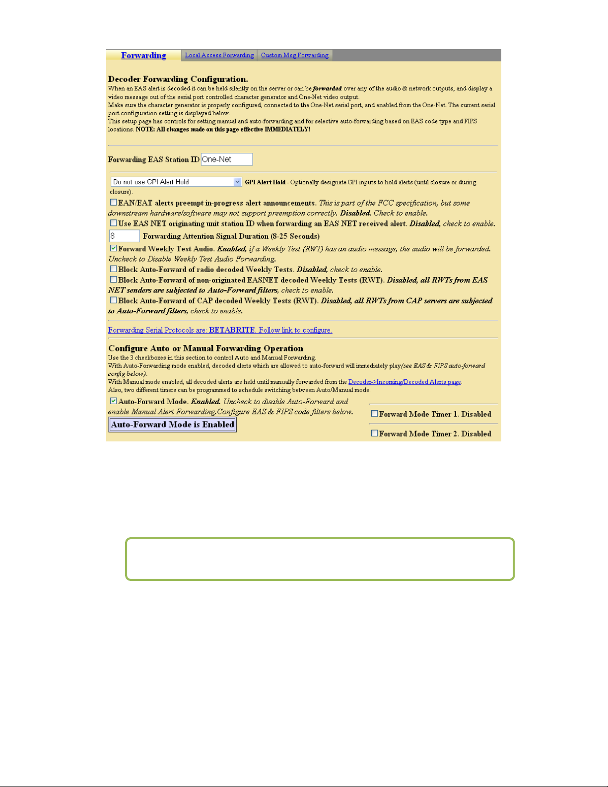
Setup > Decoder > Forwarding
Forwarding EAS Station ID
Type up to 8 characters in this text field to identify the Station ID for this One-NetSE.
This code will be included in all forwarded alerts; both manually forwarded and
automatically forwarded alerts.
NOTE: Forwarding Station ID is different from Encoder Station ID.
Forwarding Attention Signal Duration
Set the duration in seconds (from 8 to 25) of the attention signal tone played during alert
forwarding.
Forward audio message in decoded Weekly Tests
Click the box to select or de-select the Forwarding of the Weekly Test audio. When set to
forward, if audio is sent along with the Weekly Test it will play out along with the text
portion of the message.
- 44 -
Page 50

Block Auto-Forward of radio Decoded Weekly Tests
This feature is only used in conjunction with the EAS-NET communications between
One-Nets. Click the box to select or de-select Blocking of Weekly tests received from the
radio receivers of an EAS-NET decode device. The Weekly tests that are received via
EAS-NET will forward.
Auto-Forward or Manual Mode
Click the box to select or de-select Alert Auto-Forwarding or Manual Alert Forwarding.
When Manual forwarding is set, a user of the One-NetSE must use the Web Interface to
actively forward the alert from the Decoder Active Decoded list display. During AutoForward mode, the One-NetSE will forward alerts without review or intervention.
NOTE: Emergency Action Notification (EAN) and Termination (EAT)
alerts always forward automatically.
Duplicate Alert Handling for Decoder Auto-Forwarding
If an incoming EAS alert is determined to be an exact duplicate of a previously decoded
alert, it is completely discarded and a message is logged in the operation log. Alerts that
are duplicates except for Station ID or ORG code are stored as a decoded alert and can be
optionally auto-forwarded or held.
The three selections allow the user to either forward or discard the duplicate alert. An
example of this would be receiving a Required Monthly Test from both LP1 and LP2,
displaying the first alert and discarding the second one.
Configure Update Policy for Active EAS Alerts
This option allows you to expire an active alert when a new alert is decoded and updates
the previous alert. When enabled, you can choose what requirements the new alert must
have to expire the previous active alert.
Setup > Decoder > Forwarding: Duplicate Alert Handling & Update Policy for
Active Alerts
- 45 -
Page 51

Setup > Decoder > Forwarding: EAS Codes and FIPS Codes
Configure EAS Types for Decoder Auto-Forwarding
Click the box to select or de-select auto-forwarding for specific EAS Codes or ALL EAS
codes.
Configure Specific EAS Codes
Choose each EAS code to auto-forward. Then click Add. Codes selected for autoforwarding will appear in the Current Decoder Auto-Forwarded EAS Codes field to
the right.
- 46 -
Page 52

To remove a code from the auto-forward list, select a line in the Current Decoder AutoForwarded EAS Codes field and click Remove Selected. All operations are immediate.
Configure FIPS for Decoder Auto-Forwarding
Click the box to select or de-select auto-forwarding for specific FIPS Codes or ALL FIPS
codes.
Specific FIPS Codes
Choose each FIPS location code for the Subdivision, State (or territory) and the County
(or County Equivalent), which should be auto-forwarded. Then click Add. FIPS locations
selected for automatic forwarding will appear in the Current Decoder Auto-Forwarded
FIPS field to the right.
NOTE: When choosing the FIPS codes that you would like to filter, be sure to
choose the entire state FIPS code. This will not send you alerts for every
county, but rather it will filter in alerts that apply to the whole state. For
example: New York (036000) in the previous screenshot.
To remove a location from the auto-forward FIPS list, select a line in the Current
Decoder Auto-Forwarded FIPS field and click Remove Selected. All operations are
immediate.
4.8.2 Local Access Forwarding
This feature, when enabled, allows a custom translation of a Civil Emergency Message
when it is received. The main use for this feature is in conjunction with the Monroe
Electronics model 988-telephone device. When an alert is active a cancel button is
displayed on this page so the message can be terminated.
Custom CEM Text Translation
This box is where the actual text that the customer will see is typed. After the message is
typed the “Accept Text Translation Changes” button must be pressed.
Select Decoder Channel
This selection box is where the user programs which of the audio inputs is listened to for
the CEM to be used with the custom translation. All other audio sources will display the
standard translation of the CEM message.
Message Display Control
This selection determines how the message is repeated.
- 47 -
Page 53

Setup > Decoder > Local Access Forwarding
4.8.3 Custom Message Forwarding
This tab configures the options that your One-Net uses to control custom messages that
are decoded. The instructions on the page are self-explanatory.
Setup > Decoder > Custom Msg Forwarding
- 48 -
Page 54

4.9 Setup > Encoder
EAS alert encoding, called origination, is when the digital codes and alert audio tones and
message defined by the EAS protocol, are assembled and played over a broadcast medium
for which EAS decoders might be listening. The One-NetSE makes this task very easy. Every
action needed to encode and send EAS is available on a single page of the One-Net
Interface.
There are two sub-pages on the Setup Encoder screen:
General Required Tests
To run EAS encoding, a One-Net
This is entered on the Setup > Server page. Without a valid license key, the One-NetSE will
not show a Setup Encoder page nor the main Encoder menu tab. See section 5.1 Setup
Server. There are some configuration tasks that need to be done on the Setup > Encoder
pages before you use the One-NetSE encoder.
4.9.1 Setup Encoder > General
The General sub-page is used to set the EAS Origination code, the EAS station ID, and
commonly used alert types and FIPS locations. This page allows configuration of some
basic items needed to use the EAS encoder.
SE
SE
must be configured with a valid Encoder license key.
Web
NOTE: Unlike most configuration pages, changes made to this page
are effective immediately and do not require clicking an Accept
Changes button.
- 49 -
Page 55

Setup > Encoder > General
EAS Origination Code
Select the EAS Originator code for your system from the selection menu. This code
categorizes the type of organization sending the EAS. Select the code that best describes
your organization:
Broadcast station or cable system: Choose EAS
Civil authorities: Choose CIV
National Weather Service: Choose WXR
Primary Entry Point System: Choose PEP
- 50 -
Page 56

This code is placed in the EAS alert message when the encoder originates an EAS alert.
This same code is used for both manually forwarded alerts and automatically forwarded
alerts. If these descriptions do not match your application (i.e. Telephone Company) you
should select EAS, and place a check in the box for custom text for translation for
Origination Code. When this is enabled you will be able to customize how the text is
displayed. An example of this is shown below. When a Weekly test is activated by the
One-NetSE the displayed the text will be “NEW YORK TELEPHONE HAS ISSUED A
REQUIRED WEEKLY TEST FOR THE FOLLOWING COUNTIES/AREAS: Orleans,
NY; AT 10:36 AM ON MAR 23, 2012 EFFECTIVE UNTIL 10:51 AM. MESSAGE
FROM NY12345.”
Setup > Encoder > General
EAS Station ID
Type up to 8 characters in this text field to identify the Station ID for this One-NetSE.
This code will be included in all originated alerts; both manually forwarded and
automatically forwarded alerts.
NOTE: Encoder Station ID is different from Forwarding Station ID.
Attention Signal Duration
This control allows setting the duration of the two-tone attention signal from 8-25
seconds.
Configure Available EAS Codes for Encoder
SE
The One-Net
must be configured for the types of EAS alerts that will be used during
alert encoding. This is done by constructing a list of alert types.
- 51 -
Page 57

Setup > Encoder > General: EAS Types and FIPS Codes
To build or edit the list, choose an EAS code type from the pop down menu and
click Add. Codes selected for encoding will appear in the Configured Available
Encoder EAS Codes box to the right. Be sure and add all common EAS types that
will be used when encoding alerts from this One-NetSE. If you find you are missing
a code during encoding, you can edit the pool list at any time. To add a group of
messages of a certain type, you can click one of the buttons (i.e. Add Watches).
To remove a code from the Configured Available Encoder EAS Codes list, select
and click Remove Selected.
All operations are immediate.
Configured Available Encoder FIPS Locations
SE
The One-Net
must also be configured for the commonly used FIPS locations that will
be used during alert encoding. Just as for the EAS Codes list, a commonly used list of
FIPS locations need to be constructed from the list of all possible FIPS. The list is
referred to on the One-NetSE as the Configured Available Encoder FIPS Locations. There
are thousands of FIPS location codes, so building this list of commonly used FIPS codes
saves time during typical alert encoding. In the rare event that other FIPS locations are
needed, the list can be edited at any time.
Choose each FIPS location code for the Subdivision, State (or territory) and the
County (or County Equivalent). Then click Add. FIPS locations selected for
automatic forwarding will appear in the Configured Available Encoder FIPS
Locations field to the right. Make sure and add all the common FIPS codes that
will be used when encoding alerts from this One-NetSE. Otherwise, while
constructing an alert, you may have to return to this screen to add any FIPS codes
that are missing from the Configured Available Encoder FIPS Locations list on the
Encoder > Send EAS >General EAS screen.
- 52 -
Page 58

To remove a location from the Configured Available Encoder FIPS Locations,
select a line in the Configured Available Encoder FIPS Locations field and click
Remove Selected.
All operations are immediate.
If when encoding an alert on the screen Encoder > Send EAS > General EAS
screen, you find that a FIPS location code is missing, there is a link on that screen
back to the Setup > Encoder > General screen so you can amend the FIPS pool.
4.9.2 Setup Encoder > Required Tests
Setup > Encoder > Required Tests
The Required Tests sub-page is used to issue pre-configured Weekly Test alerts. The
One-NetSE can be configured to send a Required Weekly test with a single button push.
Required Weekly Tests
The tests can be automatically generated within a daily time frame. You can
configure the test for specific FIPS codes and the duration of the test.
You can select the box to enable or disable Automatic Random Required Weekly
Test Generation. When enabled you can edit the times and days that you want the
- 53 -
Page 59
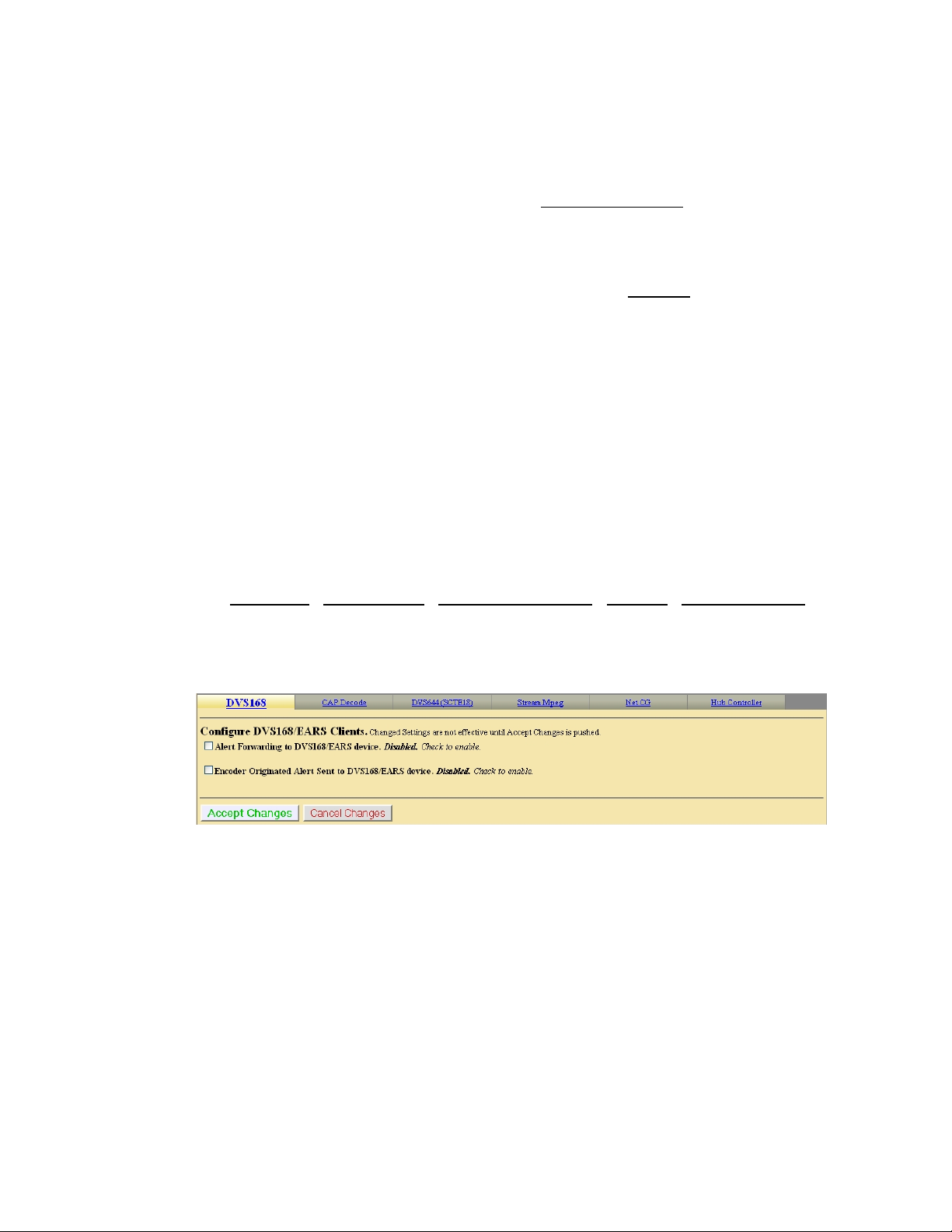
Automatic Required Weekly Test to occur by changing the between times, and the
On Days followed by clicking the Accept Time Changes button.
Configure One-Button and Automatic Weekly Test.
Set FIPS locations for and Duration of the weekly test.
Select a FIPS location(s), and then click Add Selected FIPS.
The FIPS location(s) added will appear in the list of Current FIPS locations for
One-Button Weekly Test to the right.
You can edit the subdivision in the first field for each location.
You can remove a FIPS location from the list-using Remove.
You can Enable/Disable the front panel button activation of a Weekly Test.
4.10 Setup > Net Alerts
One of the benefits of the One-Net’s inherent network nature is that it can support a variety
of methods for network forwarding/broadcast of EAS alerts. Presently the One-NetSE
supports DVS-168 network protocol, DVS-644/SCTE-18 alert messaging, Streaming Mpeg,
and Remote activation of relays using the Hub Controller Model R190A. If interfaces are not
available, follow the link to License Key Manager to Setup > Server (see section 5.1). Select
one of the protocols for editing by using the provided tabs at the top of the Net Alerts
Configuration page. A separate interface is provided per Network protocol interface type.
There are four tabbed sub-pages on the Setup Net Alerts screen. They are:
EAS NET
4.10.1 DVS168
If DVS-168 is available on the One-NetSE, use this tab to enable this protocol for
forwarding and/or sending alerts.
CAP Decode DVS664 (SCTE 18) Net CG Hub Controller
Setup > Net Alerts > DVS168
Alert Forwarding to DVS168/EARS device.
Placing a check in this box will allow Alerts that are received from a Broadcaster to
be forwarded through the One-NetSE and sent out using the DVS168 protocol.
Encoder Alert Send to DVS168/EARS device.
SE
Placing a check in this box will allow Alerts that are originated by the One-Net
to
be sent out using the DVS168 protocol.
Alert Forwarding and sending to DVS168/EARS Client
Once forwarding and/or sending have been enabled, four information fields must be
configured to identify the DVS-168/EARS host. See the provided screenshot. Enter the IP
address, the IP port, the FTP user and password, select Audio File Sample Size, and the
Audio File Sample Rate (Default is 16000 Sample/sec). Alerts with all FIPS codes can
- 54 -
Page 60

be forwarded by placing a check mark in the box to enable all FIPS to trigger
DVS168/EARS device. Alerts for specific FIPS areas can also be filtered/passed through
the protocol. Remove the check mark from the box that says All FIPS codes trigger the
DVS168/EARS device to enable FIPS forwarding control. When configured, select a list
of FIPS codes that will be used to check against the incoming forwarded alert. If any of
these FIPS are included in the incoming forwarded alert, the alert will be sent to the
DVS-168 client.
Remove the check mark from the box that says All EAS codes trigger the
DVS168/EARS device to enable EAS forwarding control. When configured, select a list
of EAS codes that will be used to check against the incoming forwarded alert. If any of
these EAS are included in the incoming forwarded alert, the alert will be sent to the DVS168 client.
Setup > Net Alerts > DVS168
Setup > Net Alerts >DVS168: FIPS and EAS Options
- 55 -
Page 61
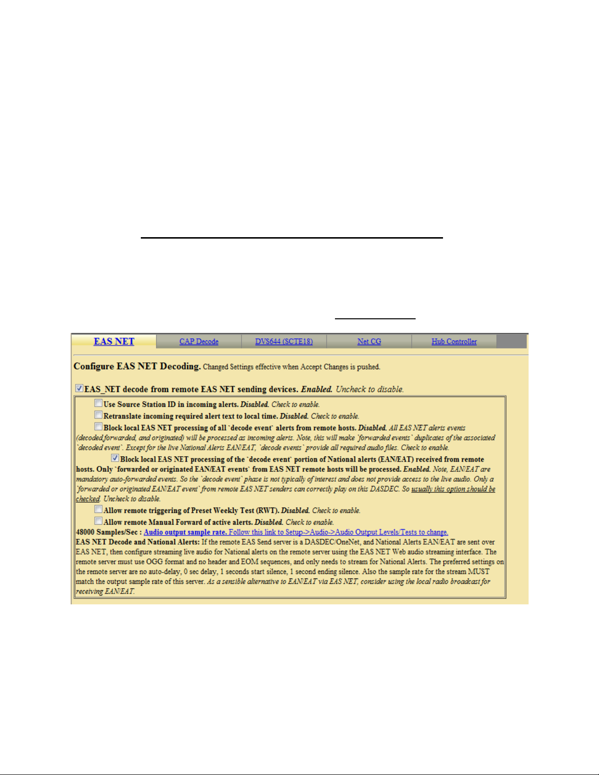
When an alert is forwarded to a DVS-168 client, a WAV file of the EAS audio is
constructed and a text file of the alert details is constructed. These are FTPed to the DVS168 client. Then a socket is temporarily opened from the One-NetSE to the DVS-168
client, and a control message is sent that describes the alert. The Operation Log will log
each of these actions and their success or failure.
4.10.2 EAS NET
There are three sections on the EAS NET sub-page to configure: EAS NET Decoding,
Web audio streaming, EAS NET Clients.
1. Configure EAS NET Decoding
Discussion: EAS Net Decoding is included with the EAS NET license key.
There is only one toggle button to enable EAS NET decode. Check the toggle labeled
"EAS_NET decode from remote EAS NET sending devices". The One-Net will
then be able to receive alerts sent via EAS NET send from a properly configured
remote One-Net. EAS NET decoded alerts are clearly labeled in the Decoder >
Decoded Alerts status page as being received from input channel EASNET. The alert
event files are stored in a separate disk storage area from audio decoded alerts. Other
than those differences, EAS NET decoded alerts are handled the same as alerts
decoded from the audio inputs. Click the Accept Changes button to save changes.
Setup > Net Alerts > EAS NET: Configure EAS Decoding
2. EAS NET Web audio streaming
Discussion: EAS Net Client Web audio Streaming is included with the EAS NET
(send) license. This provides a convenient way to stream live alert audio over a
network. This is used primarily to provide live EAN/EAT audio from EAS NET send
to an EAS NET client device (including another One-Net). The stream is not an
- 56 -
Page 62

MPEG transport stream. It is an http audio stream. Remote clients must actively load
the URL for the stream in order to play it. This can be done via most modern media
players. A One-Net with EAS NET decode will automatically use this audio stream as
a live input for EAS audio as needed. Refer to the screen shot.
EAS_NET Web (HTTP) Alert Audio streaming during alerts.
Enable this toggle to generate live web streamed audio during alerts. The default
values of the options are designed to work for EAN/EAT.
Audio Streaming on all alert types: This checkbox controls audio streaming for
National Alerts (EAN/EAT) or all alert types. For testing purposes, the toggle
"Audio streaming on all alert types" can be enabled to allow all alert types to
have audio streaming. Make sure to use this button to test live audio for any
remote One-Net EAS NET decoder.
Audio Stream Format: You can select either OGG/Vorbis or MPEG Layer 3
(MP3) audio. For audio to a remote One-Net EAS NET decoder, use OGG.
Audio Output Sample Rate Pull-down menu: The correct value for this depends
upon the destination. For audio to a remote One-Net EAS NET decoder, use the
output sample rate selected on the remote One-Net. Choices are 16000, 32000,
44100, and 48000 samples/sec.
Pre-Alert audio/alert header/attention inclusion at start of audio stream
Pre-Alert EOM Audio Streaming
These two toggle options are included for control of the total content of the alert
audio that is streamed. For purposes of this interface, alert audio consists of three
parts: (1) Pre-Alert audio/EAS Alert FSK header/Alert Attention signal, (2) Alert
audio voice message, and (3) Alert FSK EOM audio. No matter the choices, the
second part, alert audio voice message, if it exists, is always streamed. Any
combination of these options will work when streaming to a remote One-Net EAS
NET decoder. The default is to not stream the header or EOM sequence, just the
audio voice message. Use the options as required by the specific application on a
remote server. To review, the options allow the inclusion/exclusion of:
1. Pre-Alert audio/EAS Alert FSK header/Alert Attention signal
2. EAS alert FSK EOM.
Delay time before stream start; Starting silence duration; Ending silence
duration: This option allows streaming to be delayed by the duration of the alert
header. Three numeric text fields allow entry of three additional audio delay
components. Each delay is in seconds and applies to a specific location during the
audio stream. Use as needed for the specific application.
- 57 -
Page 63

Setup > Net Alerts > EAS NET Configure EAS Web audio streaming
1. Configure EAS NET Clients
Two toggles are displayed for enabling EAS NET during alert forwarding and
origination.
Alert Forwarding to EAS_NET devices: This toggle enables EAS NET send
processing during alert forwarding. It can be enabled / disabled at any time.
Encoder Originated Alerts Sent to EAS_NET devices: This toggle enables
EAS NET send processing during alert origination. It can be enabled / disabled at
any time.
NOTE: At least one of these toggles must be enabled to allow
editing of EAS NET clients. In the screen shot below, both
toggles are enabled.
Setup > Net Alerts > EAS NET Configure EAS NET Clients
2. Configure EAS_NET Client Connection
Once enabled, you can create configurations for up to 8 EAS NET clients. Each client
can be independently enabled and disabled, allowing an easy way to stop or restart a
client for a specific region.
If no client configurations exist, or if you want a new one and less than 8 clients exist,
click the Add EAS NET Client Interface button to create a new interface
configuration.
- 58 -
Page 64

To edit an existing client interface, select the named client from the pull-down menu
Select EAS_NET client and edit the fields provided in the table underneath.
To delete a client configuration, select the client and click on Delete this EAS NET
Client Interface.
To duplicate an existing client interface (a different name will be automatically
generated; less than 8 clients must exist), select the Duplicate EAS NET Client
Interface button. This is the best way to create new client interfaces that are mostly
the same as an existing one except for the IP address.
Careful! EAS NET client configuration addition, duplication, and deletion is immediate and
cannot be canceled.
Discussion: The screen shot below demonstrates an example client configuration.
The controls are described below. The example shows an EAS NET client interface
configured to use Secure Copy to send the alert information and audio files to a
remote One-Net host. This One-Net would need EAS NET Decode enabled to receive
the alert.
During alert processing, the Operation Log will log the success or failure of the EAS
NET forwarding/origination action per client.
NOTE: Every client configuration is used for whichever action of alert
forwarding and alert origination is currently enabled by the toggles
described above.
EAS NET uses a flexible set of LAN communication protocols to send EAS data to a
remote device. Generally, the remote device needs to have running software that
understands EAS NET files and data formats in order for anything useful to be
triggered by an EAS NET event. All EAS NET protocols will send an alert event data
notification file or ASCII data string from the One-Net to the EAS NET remote server
host. Most protocols also allow for sending separate data files (like audio WAV files).
Various information fields must be configured to identify and correctly communicate
to the EAS NET remote client. Common to all are the following:
Client Interface Name - This text box allows the client interface to be given a
descriptive name. These names appear in the selection list.
Client Enable/Disable - This toggle provides a quick method for enabling and
disabling the EAS NET client.
Remote EAS NET Host IP Address - The field displays the IP address of the
remote EAS NET host where the EAS NET event info is sent.
- 59 -
Page 65

EAS NET Event Transfer Protocol - Displays the Event Transfer protocol. This
is simply the LAN communication method used to send the alert event data.
Depending upon the Event transfer protocol, other configuration fields are
necessary or optional. Some protocols require passwords; others use encryption
keys. Most also provide for optional data file connections.
The event transfer protocol options are:
1. Secure Copy (SCP) – Uses the Secure Shell (SSH) network protocol for
both the data file transfers and event file transfer. No passwords are needed.
For all of the Secure Shell protocols (1.3), passwords are not used. Instead,
the One-Net public ssh key id (under /root/.ssh/id_dsa.pub and also
displayed at the bottom of the Server > Status > Network page) must be
added into the remote host's authorized ssh keys list. The keys provide for
encrypted data transfer and for secure authentication without a password.
2. Secure Shell STDIN Only (SSH) – Uses the Secure Shell (SSH) network
protocol for the event file transfer. No data files can be sent. This protocol
requires that the receiving device read the EAS NET event file from
Standard input from within the shell script. In such a configuration, SCP and
SSH login to the EAS NET user will not present to the remote platform
shell.
3. Secure Shell STDIN & Copy (SSH with SCP) – This is a variation on
protocol #2 above. The event file is sent as in #2. But the Web interface will
display a field to enter a second user account for sending data files to the
remote host. The Secure Shell (SSH) network protocol is used for both
transfers.
4. File Transfer Protocol (FTP) – Uses the File Transfer Protocol (FTP)
network protocol for both the data file transfers and event file transfer. A
password is required. FTP does not encrypt or secure passwords during
transmission. The password is sent in clear text to the remote host FTP
demon. If security is an issue, do not use or design an FTP based EAS NET
scheme. Some FTP daemons refuse passive port connections. Use the
provided checkbox to enable a non-passive connection if needed.
5. TCP event notification – Uses a TCP socket from the One-Net to the remote
host to send the alert event file. For sending the optional data files, one of
FTP or SSH SCP network protocols can be selected. A valid user account on
the remote host must be entered. The information described above for
passwords and keys apply depending upon the chosen data protocol.
6. DVS168/EARS – This is a special case of EAS NET. A TCP socket is used
to communicate an event notification, while FTP is used to send data files.
7. Legacy Mediaroom – This is a special protocol bundled under EAS NET
TM
when the Microsoft© Mediaroom
option is licensed.
- 60 -
Page 66

8. Mediaroom2 – This is a special protocol bundled under EAS NET when the
Microsoft© Mediaroom
TM
option is licensed. This is in accordance with the
Mediaroom 2.0 software.
9. MINERVA – This is a special protocol bundled under EAS NET when the
Minerva option is licensed. A TCP socket is used to communicate an EAS
event notification as per the Minerva protocol.
Remote EAS NET Host Port - The field displays the port on the remote EAS
NET host where the EAS NET event info is sent.
EAS NET User - Displays the user account name on the remote device. Files sent
to the remote host will by default be copied relative to this account home
directory.
Current Schema
The schema determines key names of the information fields sent to the EAS NET
client's remote host. It also determines file names and paths for any files sent to
the remote host. The schema can be edited by clicking on the Edit/Review
Schema button.
NOTE: The schema does NOT set the values of the client interface
fields.
Other possible EAS NET Client Configuration Options
Not all of these options will appear for every EAS NET transfer protocol.
Client sends EAS NET alert info during alert play-out
When this option is enabled (checked) the EAS NET alert info is sent out prior to
alert play-out. EAS NET prior send is only needed with EAS NET compatible
equipment that depends upon GPI controlled delayed alert play-out.
SSH Public Encryption Key link.
The SSH based protocols provide this link to the display of the One-Net public
key. This must be copied to remote host's authorization file.
Composite Audio File Send
When enabled (checked) a composite WAV file of the entire EAS audio track will
be sent as a separate file to the EAS NET client's remote host. The file name and
path on the remote host are determined by the schema.
EAS Audio File send
When enabled (checked) the individual audio sections of the EAS alert will be
sent as separate files to the EAS NET client's remote host. The file names and
path on the remote host are determined by the schema.
- 61 -
Page 67

Translation File Send
When enabled (checked) the EAS text Translation will be sent as a sep arate file to
the EAS NET client's remote host. The file name and path on the remote host are
determined by the schema.
Translation File Newline Control
When enabled (checked) the EAS text Translation has all newline characters
removed. When disabled, the EAS text Translation includes newline characters.
Video Start Delay Factor (0-10 seconds)
When set to a non-zero value, this adds delay time to the video start time reported
in the EAS NET event file. This can be useful to handle latency between the OneNet and the EAS NET remote host.
Duration Extension Time (seconds)
This allows extra time to be added to the internally calculated duration time in the
EAS NET event file. Alert Duration == Audio Duration + Extension Time
All FIPS codes trigger
If enabled, all alert FIPS codes will trigger the EAS NET client interface. In the next
screen shot this option is disabled. Set the checkbox to enable/disable FIPS code
filtered trigger control. If disabled, then the alert FIPS codes are filtered for at least
one specific match as a way to control whether or not EAS NET is triggered. Alerts
for specific FIPS areas can be filtered as a way to control whether or not EAS NET is
triggered. If All FIPS is disabled, select FIPS codes from the provided Encoder FIPS
pool or the Forwarding FIPS pool lists and add to the client FIPS list. If any of these
FIPS are included in the incoming active forwarded/originated alert, the alert will be
sent using the EAS NET client. With careful use of this feature, and with multiple
clients, one One-Net can serve many different cable regions at the same time.
Setup > Net Alerts > EAS_NET Client Configuration > FIPS trigger interface
All EAS codes trigger
- 62 -
Page 68

If enabled, all EAS codes will trigger the EAS NET client interface. In the next
screen shot this option is enabled. Set the checkbox to enable/disable EAS code
filtered trigger control. If disabled, then the alert EAS code is filtered for a specific
match as a way to control whether or not EAS NET is triggered. If All EAS is
disabled, select EAS codes from the provided lists and add to the client EAS list. If
the EAS FIPS codes of an active forwarded/originated alert match any of these EAS
FIPS codes, the alert will be sent using the EAS NET client. With careful use of this
feature, and with multiple clients, one One-Net can serve many different cable
regions at the same time.
When you finish making changes, click Accept Changes to save the configuration.
Discussion: Since EAS NET is used in conjunction with third-party management
software (on the remote host), typically, configuration details will depend upon the
exact third-party solution. Often instructions will be provided by this party. Configure
the EAS NET client interface as required.
Discussion: EAS NET Basic Operation
EAS NET operates by sending optional audio, optional text translations, and an EAS
event notification file from a One-Net to a remote device over a LAN or WAN. There
are some differences depending upon the chosen EAS NET protocol. SSH STDIN
Only does not offer sending of digital audio WAV files or text translations. DVS168,
being a legacy protocol, does not send the same type of event notification data as the
other protocols. For everything but DVS168, the remote host/server device is sent an
event text file or ASCII data sequence that contains a set of key=value style data lines
describing the EAS alert. For every protocol but SSH STDIN Only and DVS168, the
text event file by default is copied into the remote host file EAS_NET_ALERT under
the remote user home directory. This filename and path can be overridden when
configuring the client schema file. A standard set of information fields is sent in the
text file, but the actual names of the keys can be custom edited per client according to
a programmable schema. Each client can be set to use the Default schema or can use
a custom edited schema. The One-Net EAS NET client interface provides a schema
editor to create specialized schemas.
DVS168/EARS devices
DVS168/EARS can be selected as an option on the EAS NET Event Transfer
Protocol selector. See the screen shot below. Like the other EAS NET protocols, the
EAS NET remote host IP address and port must be entered. This would be the address
and port of the DVS168/EARS server. Standard DVS168 uses FTP to send data files,
so an EAS NET FTP user and password value must also be entered for a standard
client configuration. However, there is an option to disable the FTP send. This is for
servers that do not support handling digital file data but can be alerted by the DVS168
event protocol. If this option is checked the FTP user and password values are not
displayed or needed since the audio and video files will not be sent.
- 63 -
Page 69

Setup > Net Alerts > EAS NET Client Configuration - DVS168/EARS
Two other options unique to the DVS168 protocol are also provided.
1. To send just the EAS alert audio message, instead of the EAS FSK header and
EOM audio and attention audio, use the provided checkbox. Before using this
- 64 -
Page 70

2. Alert duration data format. Typically, this is in minutes, but some DVS-168
The DVS168 protocol does not provide a programmable schema. For DVS168, the
data schema is predefined and the schema selection is not displayed. As with the
other EAS NET protocols, the Video Start Delay time, the Duration Extension time,
and FIPS based net alert triggering are all configurable.
When you finish making changes, click Accept Changes to save the configuration.
DVS168/EARS operation - When a forwarded/originated EAS alert is to be sent
using a DVS-168 EAS NET client, a TCP socket is temporarily opened from the OneNet to the DVS-168 remote host. If this succeeds, and the alert is a non-national alert
(and FTP is enabled), a WAV file of the EAS audio and a text file of the alert details
are FTP'ed to the DVS-168 remote server host. Then a control message is sent over
the TCP socket that describes the alert and provides names for the data files. For nonnational alerts, this is the only notification by TCP needed. For EAN and EAT
national alerts, the audio and text files are not generated or sent, since EAN/EAT alert
audio is live and of undetermined duration. When the alert ends, a second control
message is sent over the TCP socket to signal the end of the national alert. After this,
the socket connection is "torn-down". The Operation Log will log each of these
actions and their success or failure.
4.10.3 CAP Decode
There are two sections to configure in the CAP Decode sub-page. They are, Configure
Common Alerting Protocol (CAP) Decoding and Remote CAP Server Setup.
**Quick connect to FEMA CAP Server on next page**
There is also an App-Note to help you configure your OneNetSE with CAP, go to
http://www.monroe-electronics.com/EAS_pages/eas_applicationnotes.html and
find the app-note that applies to interfacing with CAP.
option, it is important to make sure your local EAS plan allows the FSK audio
to be discarded.
interpreters have coded this differently. The selector provides two other
interpretations.
- 65 -
Page 71

Quick Connect to IPAWS CAP Server
To quick connect to the FEMA CAP Server, create a new client and follow the
options in the next screenshot.
- 66 -
Page 72

Ensure that DNS is enabled (Setup
> Network > Configuration)
Choose the IPAWS Open
2.0 Get Poll Protocol
(Last) When this says
Connected you are ready to
decode CAP Alerts (You may
need to refresh the page)
Type apps.fema.gov for the CAP
server host address and
IPAWSOPEN_EAS_SERVICE/
rest/update for the URL path
Enter your county and your state
in your FIPS list (And maybe
some surrounding counties)
Setup > Net Alerts > CAP Decode; Quick connect to FEMA CAP Server
Configure Common Alerting Protocol (CAP) Decoding
CAP Decode
This toggle enables or disables CAP decoding for the One-Net. Set it to enable to see
all of the available options for CAP Decoding.
Global CAP Options
The two advanced text to speech options (David and Allison) are available after a
purchase of the License Key (See the bottom of Setup > Server > Main/License). The
download for the voice is available online, but still requires activation. If the
- 67 -
Page 73

advanced text to speech options are not purchased, a basic text to speech engine will
be used.
CAP Text Message to Speech when CAP alert audio not available
Check this toggle to enable the text to speech option when there is no audio file sent
with the CAP Alert.
Logging Options
These options are available to keep control over what CAP Alerts make it into the log
of Decoded alerts.
Quick Connect to IPAWS CAP Server
To quick connect to the FEMA CAP Server, create a new client and follow the
options in the screen shot below.
Setup > Net Alerts > CAP Decode; Quick connect to FEMA CAP Server
Setup > Net Alerts > CAP Decoding; Configure Common Alerting Protocol (CAP) Decoding
Remote CAP Server Setup
Select CAP Input Client
This Drop-down menu allows you to choose which CAP client you are configuring.
The default clients are, CAP PUSH INPUT and HTTP Get Client1.
The CAP PUSH INPUT is available if you want to Receive CAP Alerts from a
remote push server. Though this option is available, it is not used often. If it were
used, FEMA would have to know all of the specific IP addresses that it was
pushing CAP Alerts to. Because FEMA does not know your One-Net’s IP
Address location, it is not going to push an alert to you this way.
For the HTTP Get Client1 default option, you can choose between a few CAP
Polling Protocols. Choose between HTTP, HTTPS, SSH and the IPAWS Open
2.0 option.
Add, Duplicate and Delete this CAP Interface
These buttons add a new CAP Client Interface, Duplicate the one that is currently
being edited, or deletes the one that is currently being edited.
- 68 -
Page 74

Client Interface Name
Choose a name for the specific Client Interface that you will be configuring.
ENABLE Client Interface
Check this box in order to enable the configured or new client to become active to
EAS NET CAP Alerts.
CAP Poll Protocol
Choose between HTTP, HTTPS, SSH and the IPAWS Open 2.0 option.
Poll CAP from …
WWW HTTP Get (Web URL)
Use this option to poll from a WWW Server (CAP XML, EDXL-DE, NOAA
Atom, RSS pages).
WWW Secure HTTPS Get
Use this option to poll a WWW HTTPS Secured Server (CAP XML, EDXLDE, Atom, RSS)
Secure Shell Get
Use this option to poll a SSH Server (CAP XML, EDXL-DE, Atom, RSS)
IPAWS Open 2.0 Get
IPAWSOPEN provides access to national and localized CAP formatted EAS
alerts. Enter the web host address (without https or http, e.g. apps.fema.gov and
you must have DNS enabled!). A default IPAWS URL path and internal
manufacturer specific PIN is provided. Admin users can view and edit the URL
path and other options under advanced option setup.
Under each of those polling options are very similar credentials that need to be filled
out in order to connect to the servers. The following list will show most of those
options, they may or may not pertain to all of the polling options.
CAP Server Host Address
This is the address of the server that you want to receive CAP Alerts from. In order to
use a URL, a DNS connection must be enabled. Go to Setup > Network >
Configuration to change your DNS options.
URL path portion and/or remote path and file name
Put the URL path of the server that you want to receive CAP Alerts from.
Poll Interval in Seconds
This is the number of seconds that your One-Net will take before it checks for another
CAP Alert.
- 69 -
Page 75

Assigned Station ID
Use this value to give the server that you are receiving CAP Alerts from an ID that
will appear on the log of Decoded alerts.
CAP alerts with any FIPS codes will be converted to EAS
This option, when enabled, will convert CAP Alerts that are sent to any FIPS location
to EAS on your One-Net. It is recommended that this option is DISABLED because
most often, you don’t need to know all of the cap alerts that are going on around the
country (There are a lot). When this option disabled, enter in the FIPS locations that
you want to receive CAP alerts for. The FCC requires you to receive CAP Alerts for
your county, and your entire state (Not every specific county in the state, but the
option that gives you the entire state FIPS code).
Setup > Net Alerts > CAP Decode; FIPS Codes
- 70 -
Page 76

4.10.4 DVS644 (SCTE18)
If DVS-644 (SCTE 18) is available on the One-NetSE, use the Alert Forwarding and/or
the Encoder Alert Send to DVS644 device toggles to enable this protocol for forwarded
alerts and/or originated alerts. At least one of these toggles must be enabled to allow
editing. Accept Changes must be pressed before changes to these toggles are saved.
Alert Forwarding to DVS644/SCTE-18/CEAM devices.
Placing a check in this box will allow Alerts that are received from a Broadcaster to be
forwarded through the One-NetSE and sent out using the DVS644 protocol.
Encoder Alert Send to DVS644/SCTE-18/CEAM devices.
Placing a check in this box will allow Alerts that are originated by the One-NetSE to be
sent out using the DVS644 protocol.
Setup > Net Alerts > DVS644 (SCTE18)
- 71 -
Page 77

Setup > Net Alerts > DVS644 (SCTE18)
- 72 -
Page 78

Once enabled, you can create configurations for up to 64 DVS644 (SCTE-18) CEAM
(Cable Emergency Alert Message) clients.
Each client can be independently enabled and disabled, allowing an easy way to manage
EAS for multiple regions. If no client configurations exist, or if you want a new one,
click the Add DVS644 Client Interface button to create a new interface configuration.
Careful, client configuration addition and deletion is immediate and cannot be canceled.
To edit an existing client interface, select from the provided pull down menu and edit the
provided fields. To delete a client configuration, select the client and click on Delete this
DVS644 Client Interface. To duplicate a client interface, select the client and click on
Duplicate this DVS644 Client Interface.
During alert processing, the Operation Log will log the success or failure of the DVS644
forwarding/origination action per client.
Note: Every client configuration is used for whichever action of alert
forwarding and alert origination currently enabled.
Various information fields must be configured to identify and correctly communicate to
the DVS-644 client. The most basic fields are the IP address and port. Enter these
according to the specific DVS-644 client. Often this is an MPEG-2 multiplexor, such as a
Stream Encryptor Modulator, serving a defined set of digital cable channels. Then decide
if In-Band or Out-of-Band (OOB) communication will be used and select the checkbox
appropriately. Based upon whether In-Band or Out-of-Band is chosen for the client, set
the Details Major/Minor number or the Details OOB channel. This details channel is
where the highest priority force tune alerts are sent. EAN/EAT will always cause a force
tune to this channel. By using the Alert Type Priority Selection interface, other EAS
alert codes can have the associated priority number configured based upon a severity
rating per client. DVS644/SCTE 18 provides for 16 priority values, however reserved
uses for most values mean that in practice, priority values are 0, 3, 7, 11 and 15, with 15
being the highest priority alerts. The priority of 0 has a special meaning. An alert sent
with 0 priority will establish a new set-top box or TV sequence number. The sequence
number is incremented (modulo 32) whenever an alert is sent with updated information.
The One-NetSE supports this reset mode by allowing an alert to be set to 0 priority. This
setting should only be used for one alert, and then changed to 1-15. There is also a field
SE
to extend the alert duration past the default One-Net
audio duration. Keep in mind that
the maximum allowed time for a DVS644/SCTE 18 message is 120 seconds. The OneNetSE also provides an interface to configure channel exceptions as needed. These are
channels that will ignore the alert. The interface is shown enabled in the illustration
above. It is enabled/disabled using a checkbox toggle. Another useful feature the One-
SE
Net
provides is an interface for configuring and sending a private descriptor field.
Select the Generic Private Descriptor toggle to enable and then configure the three
provided fields.
If the IP target is a multicasting router, make sure to enter a number for the Multicast
TTL field that describes the maximum number of routing jumps that will be made before
the target clients are reached.
- 73 -
Page 79

Setup > Net Alerts > DVS644: Generic Private Descriptor
Alerts for specific FIPS areas and specific EAS Codes can also be filtered before
DVS644 is triggered. See the screenshot below. Set the checkbox to enable/disable FIPS
filtered trigger control. If enabled, select FIPS codes from the provided lists and add to
the client FIPS list. If any of these FIPS are included in the incoming active
forwarded/originated alert, the alert will be sent to this DVS-644 client. With careful use
of this feature, and with multiple clients, one One-NetSE can serve many different cable
regions at the same time.
EAS Code filtering can be programmed using the same method as the FIPS code
filtering.
Setup > Net Alerts > DVS644: FIPS code filtering
When done, click on the Accept Changes button to save the configuration.
- 74 -
Page 80

4.10.5 Stream MPEG
If Streaming MPEG hardware/software is available on the One-NetSE, a tabbed page will
display under Setup > Net Alerts that allows configuration of up to two client targets. As
in the other Net Alert pages, use the Alert Forwarding and/or the Encoder Alert Stream
toggles to enable/disable the use of streaming MPEG clients when alerts are forwarded
and/or originated.
Addition/deletion, configuration, and enable/disable for each client interface is handled
just like the other Net Alert interfaces described above. Unlike those interfaces, there are
a few global settings that affect all Streaming clients. These control the video/audio
format and encoding bitrate of the stream (from the hardware). The user can also program
if they want Audio/Video, Audio only, or Video only being encoded. To account for the
latency of starting up stream encoding and actually streaming, a delay of a few seconds is
needed before audio is played for a net forwarded/originated alert. Audio delay status and
a link to the configuration field for audio delay is provided.
Streaming MPEG requires very few configuration fields. A unicast or multicast IP
address must be set, along with a port. The Multicast TTL value must be set high enough
SE
to insure the multicast data is sent past all the LAN routers between the One-Net
and
the destinations. Also, as with the EAS NET and DVS644 interfaces, FIPS and EAS code
based triggering is supported per client.
- 75 -
Page 81

4.10.6 Hub Controller (R190 and R190A)
The One-NetSE can be used in conjunction with our Hub Controller the model R190 and
the newer R190A for remote hub switching if local access channels are to be overridden
during EAS alerts. This is accomplished through this LAN controlled device that has four
independently controlled relays. Each relay can be programmed to activate by a choice of
three triggers. In addition to the three triggers it can be setup to filter its activa tion by
FIPS code(s) and EAS code(s). The One-NetSE can control up to 8 of these hub
controllers.
Setup > Net Alerts > Hub Controller
Note: Before enabling the Hub Controller, THE R190A
MUST BE SET TO AN ADDRESS THAT IS WITHIN
YOUR INTERNAL LAN.
Follow the procedure included with the Hub Controller R190A for details.
Enter the new address for the R190A as shown in the following screen and enable the
client by placing a check mark in the box. The One-NetSE will attempt to ping the R190A
and display the status. Verify that the status is OK.
You can also program the password if desired.
- 76 -
Page 82

Select the condition to close each relay that is required. Once that is selected the
Activating FIPS and Activating EAS Codes boxes will be displayed. The default setting
is “Any FIPS” and “Any EAS Codes” which triggers the relay when an alert is detected.
Setup > Net Alerts > Hub Controller: FIPS and EAS Codes
Relay activation can be programmed so that they only close when Alerts for specific
FIPS areas or EAS codes are present. Click on the “Edit FIPS” button to select FIPS
codes from the FIPS pools. When the desired FIPS codes are selected click the “Add
FIPS selected above to the list” and they will be added to the FIPS list to the right. When
finished, click on the “FIPS Editing Finished” button. Repeat this step for all of the
required relays. The same process is used for editing the activating EAS codes.
- 77 -
Page 83

- 78 -
Page 84

5 Decoder
The four choices on the Decoder page both bring up viewers of current and expired alerts. You can
choose between Incoming/Decoded Alerts, Forwarded Alerts, Originated & Forwarded Alerts,
and All Alerts. . These One-NetSE interfaces let you see exactly which alerts have been decoded and
which have also been forwarded, helping you precisely audit EAS activity.
5.1 Decoded Alerts
The Incoming, Active & Expired Alert Status page displays two kinds of information
about decoded EAS alerts. At the top of the page active EAS alert events are displayed.
Below that is the list of Expired EAS alerts. Also, at the top of the page the current
Forwarding Mode is displayed as either “Auto Forward Mode” or “Manual Forward Mode”.
The event status page can be printed out from the local host's printers, by using the Web
browser's print button. This makes it easy to compile FCC paper documents for EAS test
accounting.
Decoder > Incoming/ Decoded Alerts
- 79 -
Page 85

As can be seen from the example screenshot, every standard detail about the alert is
presented in an easy to read table. In addition, the time the alert was decoded is displayed, as
well as the time the alert was forwarded, if it was forwarded. Forwarded alerts are displayed
on the Forwarded Event Status screen. See section 6.2.
Audio portion
If the alert has an audio message, it can be played on the One-NetSE internal speaker by
clicking Play->Front Panel
on your host computer through your web browser by clicking the provided Listen on Browser
link. The host computer must be configured with a WAV file player. Alerts that did not have
an audio message will not display the two audio interfaces.
Active Decoded Alerts
The Active event list displays all decoded EAS alerts that are currently in progress, that is,
between the start and end time for the alert. An active event remains on the active list until it
reaches its expiration time, as determined by the event end time, or until it is canceled by
another event of the same type and for the same area, that redefines the event duration.
Active events are moved to the expired event list as each one finishes. Active events that are
not automatically forwarded present a button to allow manual forwarding. The example
screen above shows the Manual Forward button for the active Severe Weather Warning.
Click on this button to forward the alert. To review and edit the alert audio before
forwarding, click on the Edit/Review button. This will bring up a page that allows you to
play the original audio, select a new audio message from the local audio file list, and
optionally, add an announcement to be played prior to the alert play out.
that appears inside the alert entry. Or you can play the audio file
Decoder > Incoming/Decoded Alerts
- 80 -
Page 86

Expired Decoded Alerts
The Expired event list lets you examine past decoded alerts for any range of dates. The
following screen shows an example of the expired alerts list for a selected date range. The
next screen shows the other choices that you can select from to filter the desired range. A text
version is also available and you can select to view it in date order, or in a categorized view.
To select a date range use the provided pull-down menu and choose a Year, Month, and Day
for the From and To dates. The list will display all available data for each expired alert
decoded within the selected time period. The actual decoded headers are stored on the OneNetSE, so this information is an accurate reflection of what the One-NetSE received. Because
of its digital disk medium, a One-NetSE can archive an enormous number of expired events.
The One-NetSE will automatically remove the oldest event descriptions a s needed to reserve
enough space for new alerts. The number of stored events is at a minimum in the thousands,
so you do not need to worry about losing track of important archived information.
Decoder > Incoming/Decoded Alerts: Expired Alerts
- 81 -
Page 87

5.2 Forwarded Event Status
This page is organized exactly like the Decoded Alerts Status page. It is divided into the
same two regions: the top displays active forwarded alerts, while the bottom displays a
selected range of expired forwarded alerts. This page presents the same detailed alert
information about Forwarded Alerts as the Decoded Alert Status page. Active forwarded
events cannot be forwarded again.
5.3 Originated and Forwarded Alerts
This page is organized exactly like the Decoded Alerts Status page. It is divided into the
same two regions: the top displays active forwarded alerts, while the bottom displays a
selected range of expired forwarded alerts. This page presents the same detailed alert
information about Originated and Forwarded Alerts as the Decoded Alert Status page. Active
forwarded events cannot be forwarded again.
5.4 All Alerts
This page is organized exactly like the Decoded Alerts Status page. It is divided into the
same two regions: the top displays active forwarded alerts, while the bottom displays a
selected range of expired forwarded alerts. This page presents the same detailed alert
information about All Alerts as the Decoded Alert Status page. Active forwarded events
cannot be forwarded again.
- 82 -
Page 88

6 Encoder
EAS alert encoding, called origination, is when the digital codes and alert audio tones and message
defined by the EAS protocol, are assembled and played over a broadcast medium for which EAS
decoders might be listening. The One-NetSE makes EAS encoding and alert origination easy,
accurate, and quick. From a single, uncomplicated web page, EAS alerts can be constructed and
issued.
Only a One-NetSE that has been configured with a valid Encoder license key (see Setup > Server,
section) will offer the encoding feature. Without a valid license key, the One-NetSE will not show
the main Encoder menu tab (nor will it display the Setup > Encoder option button under the "Setup"
main tab). There are some configuration tasks that need to be done on the Setup Encoder pages
before you can use the One-NetSE encoder. Make sure your One-NetSE has been configured with
Setup > Encoder prior to attempting EAS encoding.
There are four choices on the Encoder page: Send EAS and Originated Alerts, Originated &
Forwarded Alerts, and All Alerts.
6.1 Send Alert
When you select Send Alert, the Encode and Send an EAS Alert page is displayed. This
page has two sub-page options: General Alerts and One-Button EAS. Using the One-
button EAS screen is a simple way to encode and issue weekly test alerts using a single
mouse click. To encode general specific alerts, the General Alerts page is used.
Encoder > Send Alert > General Alerts
- 83 -
Page 89

Encoder > General Alerts
- 84 -
Page 90

Encoder > General Alerts: Alert Action Table
6.1.1 General EAS
To construct and send an EAS alert, you need to set six items on the General EAS page:
The EAS alert code;
The starting time (effective time) of the alert;
The alert duration
The FIPS locations codes for the alert;
The audio message, if any, for the alert.
The audio announcement message, if any that will precede and follow the alert.
The values for these items are presented using pull-down and selection menus.
Select EAS Code
To set the EAS code, select from the codes presented under the Select Available EAS
Code pull-down menu. The codes shown are the ones that were added to the list on the
Setup >Encoder screen. If the list needs to be corrected, use the link Select Available
EAS Code to return to the Setup > Encoder screen. Configure Available EAS Types for
Encoder as needed. See section 5.9. Then return to the Encoder >Send EAS >General
page to continue constructing the alert.
NOTE: Only specially configured One-Net’s will allow origination of
the National alerts Emergency Action Notification & Termination (EAN
& EAT).
- 85 -
Page 91

Serial Interface Status and Optional Override
Directly under the EAS code selection menu is an active hyperlink that displays the
current status of the Origination serial interface CG protocol. This will inform the user if
the serial interface is offline or online, and which protocol is selected if online. It also
displays if the protocol has been bypassed by the checkbox toggle below. The active link
points to the Setup >Video/CG page. The link can be followed to quickly change the CG
settings used during alert origination.
Check to Bypass Use of Serial Interface
If you check this box, the current serial protocol will not be used during the alert
origination.
Set Effective Time for alert
The default effective time is the current time. You can set the effective (starting) time for
the alert.
Set Alert Duration
The default duration is 15 minutes. You can change the alert duration
Set FIPS locations
An EAS alert must be issued for specific locations. Until FIPS location codes are entered,
the One-NetSE will not present a Send Alert? display. Instead, a message **Need to Add
FIPS Codes** will display in place of selected FIPS codes. Also, a message "Alert NOT
Ready to Send: Specify FIPS" is displayed at the lower right on the page.
To set the FIPS location(s) for the alert code, select from the list presented in the
box under Available FIPS Locations. The codes shown are the ones that were
added on the Setup >Encoder> General screen.
If the list needs to be corrected, use the link Available FIPS Locations to return to
the Setup > Encoder > General screen. Configure Available Encoder FIPS
Locations for Encoder as needed. See section 5.9.1. Then return to the Encoder
>Send EAS >General page to continue constructing the alert.
For each location, Select one or more FIPS, and click Add Selected FIPS. Up to 31
FIPS location codes may be selected using the provided FIPS selection table.
As you build the list of current FIPS locations for the alert, these locations display
on the right. The sub-region of the FIPS location can be edited for every chosen
location. If a different sub-region is desired, select one of the choices presented in
the pull-down menu displayed to the left of the FIPS code.
If a FIPS location needs to be removed from the list for the alert, click the Remove
option that is presented with every chosen FIPS entry.
After you select the FIPS location(s), the "Alert NOT Ready..." message changes to
a Send Alert? Button. The alert can be sent immediately if no audio message is
needed. However, often the alert should have Pre-Alert Audio Announcement or an
Audio File.
Pushing the Reset button will restart the entire process.
- 86 -
Page 92

Select Alert Audio (Optional)
Use this pull-down menu to select a prerecorded audio file to play during the alert. This
option is not presented for Required Weekly Test (RWT). Audio files can be added to
this list in two ways. WAV files can be uploaded using the Upload interface described
below. Or, audio files can be directly recorded into the One-NetSE by using button
described below. When an audio file is selected, its duration will appear, along with a
link to play the file on the host browser, as well as two buttons. The Preview Selected
SE
button will play the file over the One-Net
internal speaker. The Delete Selected button
will allow file deletion from the audio list.
Record Audio File (Optional)
When the Record Audio File
button is pushed a new, temporary page is displayed. This
page provides controls for recording audio with a microphone.
The microphone must be connected to the main microphone input jack at the back
SE
of the One-Net
. To record, provide a unique file name for the audio file by
entering the name in the "New Audio Filename" text field. (A unique file name is
one not already used in the provided "Select Audio File" selection box. If you use
an existing name, the original file by that name will be overwritten.)
Push the Record Audio button and speak.
Click on the Stop Audio Recording
button when complete.
The file will appear in the Audio File selection box. It may be previewed on the
One-NetSE using the "Preview Selected" button. The duration of this file must be
under two (2) minutes. The One-NetSE will automatically cut off recording at 2
minutes in order to insure this limit.
Once the file is correct, select it from the Audio File selection box. In the example
above, the file floodevac.wav has been selected.
Select Pre-Alert Audio Announcement (Optional)
Use the pull-down menu to select a prerecorded audio announcement to precede the
actual alert announcement. The selected file has the duration displayed.
Select Post-Alert Audio Announcement (Optional)
Use the pull-down menu to select a prerecorded audio announcement to play after the
actual alert announcement. The selected file has the duration displayed.
Upload Audio .WAV file to One-NetSE Server.
You can upload a pre-recorded digital audio file (in the .wav format) from your local host
computer file system using the provided Upload Audio .WAV file to One-Net server
interface at the bottom of the page. The browse button will use your browser’s file system
navigator to find an audio file. Once the file is selected, click Upload WAV file. The file
will now appear in the Audio file lists.
6.1.2 Send Alert
Once the alert has been constructed correctly, click on the Send Alert? Button. The One-
SE
Net
will present a confirmation page with a review of the encoding details.
- 87 -
Page 93

Review of Prepared Alert
Examine the confirmation page prior to sending the alert. If the alert is correct, it can be
sent by clicking the Yes, Send Alert! button. Or you can cancel the send alert with the
Cancel Alert button. If the alert send is canceled, the One-NetSE will go back to the
Encode and Send an EAS Alert page. Change the alert information before attempting to
send the alert.
If the EAS alert data is accurate, and you are ready to issue the alert, click on the Yes,
Send Alert! button. The alert will be "originated", that is, played, out of the selected
One-NetSE audio output ports. The originated alert audio ports are selected from either the
Setup Encoder > Audio or the Setup Audio > Encoder screens. See section 5.6.3.
During the origination time, the front panel red LED will be lit and the audio of the alert
will play from the built-in One-NetSE internal speaker. For the duration of the issued alert,
the One-NetSE will periodically crawl the alert text across the front panel LCD. The LCD
text for the letter “O” will precede the alert, indicating a One-NetSE originated alert. The
details of this alert will be viewable on the screen Encoder Originated Alert Status
[Encoder > Originated Alerts].
6.1.3 One-Button EAS
The One-NetSE allows required weekly tests to be preconfigured on the Setup > Encoder
> Required Tests page. Once these have been configured, the Encoder > Send EAS >
One-Button EAS page will present a button to issue the alert. This makes it simple to
send these test alerts, without having to select details. The alert start time is set to be
effective immediately. The serial interface status and bypass are also present as in the
General EAS screen. See section 7.1.1
6.2 Originated Alerts
The Encoder Originated Alert Status page is organized just like the Decoder Decoded Alert
Status page. You can look at the details of every alert originated from the One-NetSE. The
following types of alerts are displayed:
Scheduled Originated Alerts. Scheduled alerts occur when random Weekly tests are
automatically scheduled and when specific alerts are sent starting at a future time.
Currently Active Originated Alerts
Expired Originated Alerts
You can select specific dates for expired alerts using the FROM and TO date selection pulldown menus or the other choices shown under the Decoded Alerts Section 6.1.
- 88 -
Page 94

7 Testing One-NetSE Encoding and Decoding
A good way to test the One-NetSE is to have a second sound card installed and run an audio cable
between the output of the second audio card into the input of the first card. Make sure the origination
audio out is set to play over the auxiliary audio output and that one decoder is operational on the
Main audio input (use Setup > Audio > Decoder). Turn off forwarding audio toggles. Then run the
Encoder and send the alert. The One-NetSE will both send and decode the alert.
8 Server
The Server pages present all kinds of system status and helpful information.
There are three choices on the Server tab:
Help Status Logs
8.1 Server > Help: Server Help
The Server Help page displays information about the One-NetSE, EAS, EAS Message
Protocol, and EAS Codes.
8.1.1 About One-NetSE: One-NetSE EAS Encoder/Decoder Platform
Presents information about the installed One-NetSE software and about Monroe
Electronics and Digital Alert Systems, LLC.
Server > Help
8.1.2 About EAS: The Emergency Alert System
Presents information about the Emergency Alert System: purpose, operation,
management, your responsibility as a broadcaster, and the future of EAS and One-Net
- 89 -
SE
.
Page 95

8.1.3 EAS Message Protocol
Presents information about the EAS protocol from the FCC.
8.1.4 EAS Codes: EAS Code Table
Presents a list of the EAS event codes that are presently authorized, both national and
state.
8.2 Server > Status: One-NetSE Server Status
The One-NetSE Server Status Main page displays a summary of status information about
the One-Net
Status, Disk Usage and SSH DSA Public Encryption Key are displayed. This page is a
convenient way to see at a glance the state of the decoder channels and the basic encoder and
decoder configuration.
SE
on a single page. The Platform ID, System Uptime, Decoder and Other Server
8.3 Server > Logs: Server Logs
The Server Logs screen has six sub-pages: Web Session Log, Operation Log, Operating
System Log, Security Log, Boot Log, and Email Log.
8.3.1 Web Session Log: One-NetSE EAS Encoder/Decoder Platform
Presents dated information about user access to the One-NetSE. Two settings are
available. If the Today’s log checkbox is checked, then this page will always show the
Web session log for the current day. To view archived web session log files, uncheck the
box. Then select a log for a specific date. You can then show the log for the previous or
the next day. Log files a day old or more past can be deleted using the provided delete
button. This page can be refreshed by clicking on the Refresh button at the bottom of the
page to reveal new information.
8.3.2 Operation Log
Presents dated information about the One-NetSE Operation. This interface works the same
as the one for the Web session log. All important EAS events will be shown here.
8.3.3 Operating System Log
Presents the last 500 lines of the Linux system System Log.
8.3.4 Security Log
Presents the last 500 lines of the Linux system Security Log.
8.3.5 Boot Log
Presents the last 500 lines of the Linux system Boot Log.
8.3.6 Email Log
Presents the last 1000 lines of the Email Log.
- 90 -
Page 96

9 Typical Tasks
This section of the manual is intended for users that have already set up and configured their One-Net(s)
and would like to know what to do to complete certain tasks, and also how to manage when alerts are
present. When your One-Net is up and running, there are still things that need to be done in order to be
in compliance with the rules placed on all EAS regulations. Things like, receiving and forwarding alerts
as well as keeping accurate and accessible logs of that data. This part of the manual will step you
through the process on many different tasks, and it will be able to show you what may happen, or what
should happen in the most common situations.
Originating/Encoding an Alert
Originating and Encoding mean the same thing; it is the creation of an alert that can be forwarded over
your own broadcast. When this alert is forwarded over your broadcast, any station that is tuning into
your station will receive and decode that alert in that station’s own EAS device. Simply, any station that
is listening to your station on their EAS device will receive and decode the alert that you sent out, just
like if you were to receive an alert from another station over your radio tuners. This is a useful tool for
making custom alerts and putting them on your own broadcast.
Originating an Emergency Alert
In the beginning of the section, you configured your settings for setting up a general Encoded
Emergency Alert. So this will be pretty simple.
To create an originated alert to forward over your broadcast, go to Encoder > Send Alert >
General Alerts and configure the options to how you want your alert to look. The options are put
into six steps for you. An example of setting up an alert is shown next in a screenshot:
- 91 -
Page 97

To forward the alert over your broadcast, click on Send Alert, and then you will be sent to a
confirmation page. Confirm the alert, and it will be sent out over your broadcast.
- 92 -
Page 98

Retrieving the Logged Alerts in your One-Net
So you have been decoding alerts, encoding your RWTs and forwarding alerts for a while now, and you
have done a great job. But all of a sudden, the FCC comes to your station’s doorstep and demands that
you prove to them that you have been sending out all of your RWTs and have been receiving alerts from
other stations. You might panic, but the truth is it is really simple, and it’s a good thing you have these
next couple of steps to prove to them how you have been following all of the rules.
Steps to Viewing/Downloading/Printing your One-Net’s logged alerts:
1. Go to Decoder > All alerts in the One-Net Online interface. It should look something like this:
By the way, your One-Net saves all of your Encoded, Decoded and Forwarded alert information
automatically.
2. In the yellow box on the screen shot, you want to select the amount of time you want to look
back when you view your alerts. So if the FCC says “We want the alerts from the past month”
then select the option that shows them the alerts from the past month.
3. The big red arrow in the screenshot points to a hyperlink that says Click for text version
the key to retrieving, downloading and printing your alerts.
a. To view your alerts, simply click on the hyperlink. This will take your web browser to a
new page that shows you all of the alerts that apply to the selected time you chose. If you
want to go back, just use the back button in your web browser. You can print this by
pressing Ctrl + P on your keyboard, and then proceeding with the printing options.
b. To download your alerts, right click on the hyperlink. In the right click options, you will
be given the choice to pick “Save link as…” From there, you can save the .txt (text file)
file anywhere on your computer. This file can be opened by a simple text file viewer.
This can also be printed from the text file.
c. Lastly, you can just print the logs by clicking on the button next to the hyperlink. If
you have a default printer configured to your One-Net, then clicking on this button will
automatically begin printing all of the alerts in the selected amount of time that you
chose.
. This is
- 93 -
Page 99

That’s basically it. There is an advanced option next to the print button that organizes your printout in
groups of forwarded, decoded and encoded alerts instead of it all being in order by the date, but you
don’t need to enable that in order to print out your reports.
Retrieving your One-Net OpLog:
To retrieve a One-Net Op Log:
1. Log in to the One-Net
2. Go to Server > Logs > Operation Log
For the current days’ log
3. Make sure View Today’s Log is checked.
4. Click (or right-click to save) the hyperlink “Click for Text version of log file
day’s file
For archived logs
3. Uncheck the View Today’s Log box.
4. Using the pull-down selection boxes select the Year, Month and Day to retrieve the log. (Note: The
selection boxes show only dates with stored data, therefore not all days may appear.)
5. Click (or right-click to save) the hyperlink “Click for Text version of log file
day’s file
Log files will either show on the screen or be saved as a text (.txt) file.
” to show the current
” to show the current
Installing a license key
To install a license key (CAP Plus, for example):
1. Log in to the One-Net
2. Go to Setup > Server > Main/License page
3. Locate the CAP Plus field then insert the license key that should have been given to you in an
email.
The CAP LICENSE KEY below is between the quotes and it is important to verify the serial number
matches the serial number of the unit. Note it is much easier to cut and paste instead of typing, as these
keys are case, space and all character sensitive.
S/N xxxxx CAP PLUS “xxxxxxxxxxxxxxxxxxxxxx”
4. Once the key is copied into the appropriate field, scroll to the bottom of the page and click
"Restart Server"
5. After the software restarts, log back in and verify the field is and shows the word :VALID
NOTE: (Specifically for the CAP Plus Key) The One-Net must be at Version 2.0-0_a03 or above to
provide the FEMA IPAWS interface. The version number shown in the upper right-hand box is only the
first portion of the entire version number. Clicking on the version number will take you to the "About"
page where you will see the "whole" version number. You can download the latest version
at http://www.digitalalertsystems.com/registration_updates.html
- 94 -
Page 100

Backing up the One-Net configuration file
You have been using your One-Net for a while now, and you want to save the settings that you have
carefully adjusted and configured your One-Net to. Here is how to save that configuration:
1. Log into the One-Net.
2. Go to Setup > Sever > Configuration Mgmt
3. To ensure the latest configuration is stored click on the Make Backup button. This will create a
backup file with the current date and time as the initial part of the file name. An example backup
file may be 2012_04_12_19_26_One-Net_config.zip where the file was created on April 12,
2012 at 5:26 PM.
4. Look for the title List of Configuration Backup Files and the pull down selector directly below.
5. Select the file created in step 3 above. The list is sorted numerically (from earliest date at the top)
then alphabetically
6. The screen will refresh and the selected file will be queued in the blue hyperlink area
Download selected configuration file
'yyyy_mm_dd_hh_mm_One-Net_config.zip'.
7. Right click on the file name will present a list of options.
8. Select Download Linked File… or Save link as…
9. Navigate to the location you wish to store the configuration file on the external computer or
storage device (ie USB stick, network drive, etc.)
10. Click Save to store the backup copy of the configuration file. NOTE: the network interface IP
addresses are purposely not retained in the configuration file. It may be useful to record this
numbers in a separate file or take a screen shot of the Setup > Network page for your records.
Uploading an audio file in a One-Net
Step One – Generate an acceptable audio message.
The EAS handbook recommended a very simple message "This is a test of the Emergency Alert
System."
There is no requirement regarding the message contents, however brief is good.
1. Have one of your announcers create an RMT audio message and store this as a .wav file.
(It is recommended that you name the file xxxx-RMT.wav where xxxx is your station ID)
2. Place the file on a computer with access to the One-Net
Step Two – Load the .wav file into the One-Net
There are several ways to upload an audio file into the One-Net, this is just one.
1. Log into the One-Net.
2. Go to Encoder > Send EAS > General EAS
3. Go to the bottom of the page and select the box Display audio record and upload
interface (hidden, check to display).
4. When he box expands click "Choose File"
5. Browse the file options and locate the xxxx-RMT.wav file
6. Select the file and select "Choose" or "OK" The file name should now appear in the blue box.
7. Select "Upload .WAV file" This will place the file in the One-Net and make it selectable when
executing an EAS event
8. Process is complete – you can exit now
Step Three – Using the .wav file in an EAS message
Once the file has been uploaded it is available for selection as part of the EAS play out.
To use this for an RMT:
- 95 -
 Loading...