

Page 1

1
Instruction Manual
EAS DIGITAL/ANAL OG
OVERRIDE INTERFACE
Model 988
PC Software version 1.06
Emergency Alert Systems
CATV Switching and Control
585-765-2254 fax 585-765-9330
100 Housel Ave. | Lyndonville | NY | 14098
www.monroe-electronics.com
Page 2

2
Warranty 3
Specifications 4
General Overview 5
Getting Started 6 -13
Installation 14
Operation 15
Local Authority Instructions 16
Front Panel View/Figure 1 17
Wiring Diagrams 18, 19
Table of Contents
Page 3

3
Warranty
Monroe Electronics, Inc. warrants to the owners, each instrument and sub-assembly
manufactured by them to be free from defects in material and workmanship for a
period of one year after shipment from factory. This warranty is applicable to the
original purchaser only.
Liability under this warranty is limited to service, adjustment or replacement of
defective parts (other than fuses or batteries) on any instrument or sub-assembly
returned to the factory for this purpose, transportation charges prepaid.
This warranty does not apply to instruments or sub-assemblies subjected to abuse,
abnormal operating conditions, or unauthorized repair or modification.
Since Monroe Electronics, Inc. has no control over conditions of use; no warranty is
made, or implied as to the suitability of our product for the customer's intended use.
THE WARRANTY SET FORTH IN THIS ARTICLE IS EXCLUSIVE AND IN LIEU OF
ALL OTHER WARRANTIES AND REPRESENTATIONS, EXPRESSED, IMPLIED
OR STATUTORY INCLUDING, BUT NOT LI MITED TO THE IMPLIED
WARRANTIES OF MERCHANTABILITY AND FITNESS. Except for obligation s
expressly undertaken by Monroe Electronics, in this warranty, Owner hereby waives
and releases all rights, claims and remedies with respect to any and all warranties,
express, implied or statutory (including without limitation, the implied warranties of
merchantability and fitness), and including but without being limited to any obligation
of Monroe Electronics with respect to incidental or consequential damages, or
damages for loss of use. No agreement or understanding varying or extending the
warranty will be binding upon Monroe Electronics unless in writing signed by a duly
authorized representative of Monroe Electronics.
In the event of a breach of the foregoing warranty, the liability of Monroe Electronics
shall be limited to repairing or replacing the non-conforming goods and/or defective
work, and in accordance with the foregoing; Monroe Electronics shall not be liable for
any other damages, either direct or consequential.
Return Policy
Materials returned to Monroe must have a Return Material Authorization number. To
obtain a RMA number, contact our A/V Switching & Control Customer Service at 585765-2254 or fax 585-765-9330. Customers have 30 days to determine that the
product ordered fills their need and performs as described in Monroe’s literature.
Units returned for approved repair or credit, must be in the original packaging
including all parts and paperwork plus be in very good physical condition. If not, the
customer is billed the cost to refurbish the unit and for missing accessories and
merchandise. No products may be returned for exchange or credit after 12 months
of the shipment date. Monroe reserves the right to repair or replace units under
warranty.
Page 4

4
Number of rings before answer
1 to 8
Automatic time out
1 minute with no or incorrect activities
Access code selection
Any three numerical digits
Alert Duration
15 minutes to 24 hours
Number of FIPS Codes
Nine maximum
Power requirements
+ 12 volts DC; 94-240 VAC wall unit supplied
External switching
Two (2) SPDT relays (SWITCH 1 AND SWITCH 2)
2 Amp 30 volts DC non-inductive loads
Indicator lights
One (1) to indicate “TELEPHONE OFF HOOK”
Maximum message length
60 seconds
Specifications
Equipment Supplied
Power Supply
11 position plug USB programming cable 25 foot modular line cord CD with setup program and instruction manual
Page 5

5
General Overview
Some EAS decoder/encoders have no installed or available provision for local access to the emergency alert system in place in their area.
To provide local access for these systems, the 988 offers a means to activate
the decoder for selected FIPS areas with a predefined alarm message display
and allows the caller to record a message to be played to the telephone caller
upon answering.
Page 6
6
Getting Started
The following “Getting Started” steps are programming functions that must be
accomplished before installing your 988. Please refer to the installation
instructions on page 15 in conjunction with the following steps.
After removing the unit from the shipping package, install the setup program on a
PC running Microsoft Windows. A USB port must be available.
Connect the power supply to the 988, and install the USB cable from the PC to the
988.
The 988 Setup Software
The 988 software will setup the unit via the USB (Programming) port. It allows the
programmer to set up the time in GMT (Greenwich Mean Time), Number of Rings
to Answer, Access Code, Station ID, Duration, Originator, Event Type, and up to 9
FIPS codes.
Installing USB driver
Upon initial connection of the 988’s Programming port to the USB of the computer,
it will ask for the driver location. The driver is a program that is included on the CD
supplied.
1. Insert the 988 Setup CD into your computer. If the splash screen
comes up, click Exit.
2. Connect the 988 Programming port to your computer’s USB port with
the cable provided.
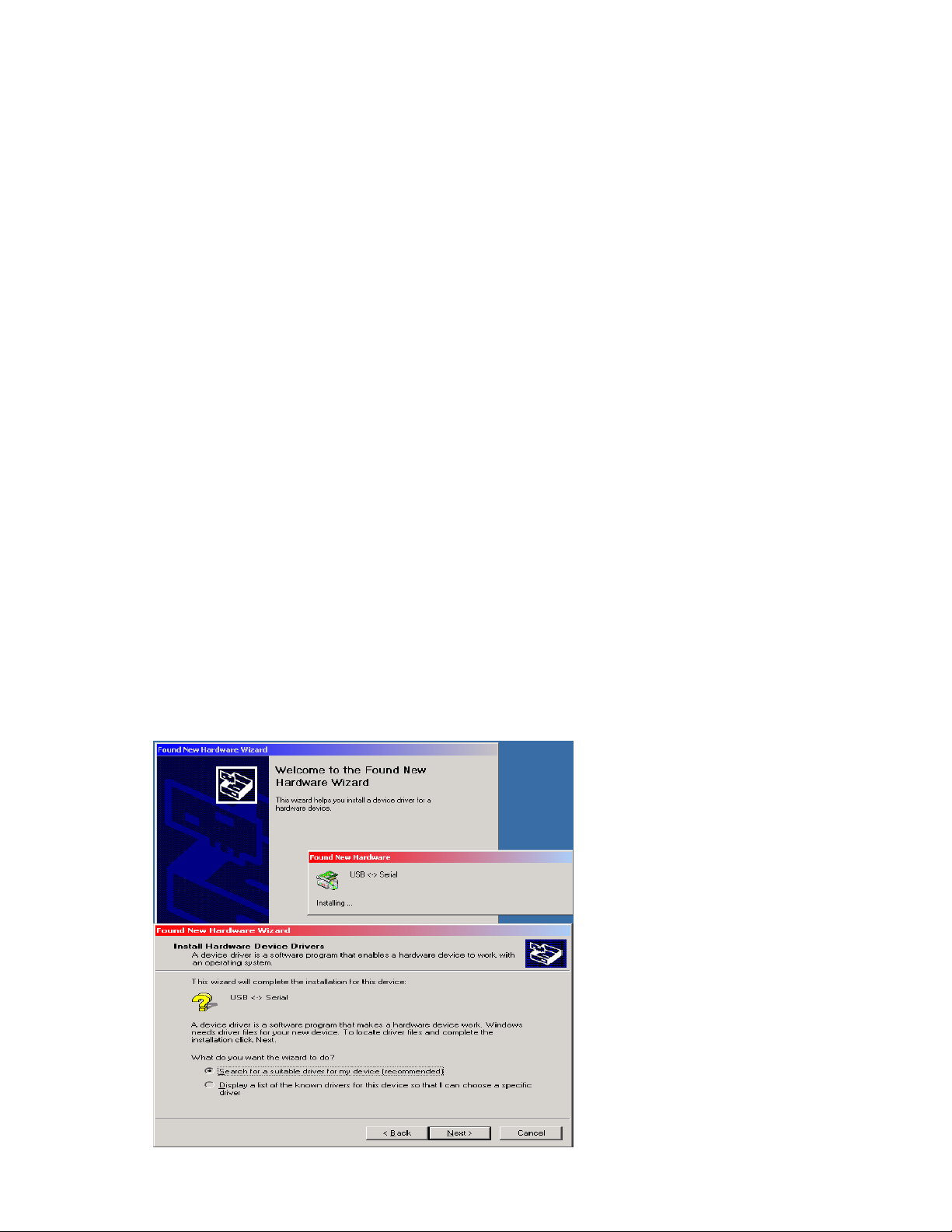
3. Supply power to the 988 unit. If the driver is not yet installed for the
USB port, the following will come up. Follow the instructions:
Select “Search for a
suitable driver for my
device” , then click the
Next.
Page 7

7
Select the CD-ROM drive, and
then click Next.
Click Next again.
Click Finish. Windows may
repeat the process again to
complete the USB driver
installation.
Page 8

8
Installing the 988 Setup software
Insert the 988 CD into your computer. The following screen will come up.
Click on Installation.
Click on Next. Then follow the instructi o ns.
When finished a 988 Icon will be placed on your desktop.
Page 9

9
Running the 988 Setup program
Click on the 988 icon on your desktop to start the program. It will first ask for the
comport connection to the 988’s USB (Programming) jack. If you completed the
installation for the 988 USB driver as mentioned in the previous section, Windows
assigned a COM port number for the USB po r t.
If you’re not sure what comport is
available, click No to search and
select the appropriate one,
otherwise, select Yes.
After selecting the comport, click on the Read from 988 button to see if
communications have been established. If an error occurs, click on the
Connection drop-down menu on the toolbar to select another comport, then try
reading from the unit again.
Main Screen Toolbar Functions
Connection
To select and open a comport to the 988 unit.
Setup Menu
Includes the following Sub Menus.
DATE and Time
Set GMT (Greenwich Mean Time) on the unit.
Page 10

10
Firmware Version
Display the firmware version in the 988.
Firmware Update
Downloads the firmware to the 988. This is for future updates.
You can acquire the firmwar e from Monr oe Electronics. Then
click on this menu and follow instructions to download it to the
unit’s flash memory.
Test Alarm Tones
Sends a continuous tone for system level adjustment.
Restore Factory Default
Enters the default setup on screen.
Main Screen The foll owing settings must be programmed and stored into the 988.
Number of Rings to answer __ 1-8.
Access code ___ Upon telephoning the unit, a 3-digit code must be entered to
access the unit.
Station ID ___ Identification of the station that broadcasts the message.
Duration ___ The valid time period of the message. In 15-minute increments if
less than 1 hour, in 30-minute increments if more than 1 hour.
Originator ___ Identifier for which site or station created and transmitted the EAS
message. There are five options that can be set:
Broadcast/Cable System___ EAS
Civil Authorities___ CIV
Emergency Action Network___ EAN
National Weather Service___ NWS
Primary Entry Point___ PEP
Event___ The nature of the event or EAS message. This selection determines the
text that will be displayed to the customer.
Page 11

11
To Set Date & Time (GMT Greenwich Mean Time)
All EAS alerts are encoded using GMT or UTC.
First verify that the time and date on your computer is accurate.
On the tool bar click on Setup – Date and Time. The following screen will be
displayed.
This screen shows the local date and time from your computer, and calculates
GMT based on the time zone selected. Click the Select Time Zone drop-down box
and select the time zone where the 988 will be installed. The offset from the
selected time zone will now be displayed under the box. The program has now
calculated GMT time from your time zone. To load GMT time in the 988, click on
the Submit Date & Time to 988 button.
To verify that the time is programmed correctly, click on the Read Time from 988
button.
Click on Close to get back to the Set Up screen.
Page 12

12
Add FIPS code
On the main screen click the Add FIPS button to open the following window.
These will be the available FIPS codes to be used when originating an alert.
Select the County
Subdivision, normally set
to All (0), FIPS State,
FIPS County, and click on
Add to add it to the list of
available counties.
Click Close when done
selecting.
Page 13

13
Storing The Setup to the Unit
Click on the Store
to 988 button to
send and store the
setup to the 988
unit.
Programming is now complete. The USB cable can be disconnect from the
988 and you can proceed to the next step and record your access message.
Recording Your Access Message
Upon initial use of the 988, you must enter an access message.
To do this press and hold the record button located through the Store access hole
in the instrument’s front panel (refer to picture on page 17.) In a quiet area and
speaking in a normal tone of voice with your mouth about 6 or 8 inches from the
microphone on the PC board, enter the message. Please leave a silent period for
4 or 5 seconds after speaking to allow a time for entering the access code, before
releasing the record butt on. When the unit answers the call this message will
repeat until the access code is entered. Note: If the correct access code is not
entered in 60 seconds, the 988 will automatically hang up.
Message to Caller Level
The gain controls are adjusted as follows:
Set all four (4)-adjustment pots to the center of their range.
Dial up the unit and listen to the message.
Adjust the MESSAGE - TO CALLER pot for a comfortable level without distortion,
and then hang up.
Enter the access code that has be en pr og r am med into the unit.
Page 14

14
Installation
Connect the telephone cable to the RJ-11 plug, two wires for balanced audio from
the screw terminals marked AFSK/AUDIO to the balanced input of the
encoder/decoder audio input, and the power supply wires to the + and – screw
terminals marked for power. The white wire is the + wire.
If your audio input is unbalanced, connect a wire to the AFSK/AUDIO terminal
nearest to the power terminals, and connect this wire to the audio input on your
encoder/decoder. Then connect a wire from the terminal marked GND nearest to
the power terminals, and connect this to the ground on your encoder/decoder.
Plug in the power supply.
Make sure that your encoder/decoder has been set to accept an audio input from
the terminals you have wired it to, and is configured to accept signals from this
input as if they were from a separate radio receiver.
Note: During setup, you may want to disable the output from the encoder/decoder
so that no alarms are displayed through the cable system.
Page 15

15
Operation
Monroe Model 988 interfaces a two-wire (POTS) telephone service with control
switching and audio control signals to an FCC approved encoder/decoder.
Upon answering, the unit begins playing back the message stored by the operator,
and looks for a series of DTMF tones corresponding to the three-digit access code.
After picking up the telephone line, if no activity is detected for a period of 1
minute, the unit disconnects the telephone line. If the user does not enter the
correct access code within a period of 1 minute, the unit will disconnect the
telephone line.
Once the telephone caller enters the three-digit access code, the unit will cease
playing the message and proceed to the next stage of operation.
Additionally, after the access code has been entered, two separate relays will
actuate. Contacts are available on the screw terminals of the connector as Switch
1 and Switch 2.
The Caller must select the FIPS code(s) to be sent out with this alert.
To select individual FIPS codes (previously stored in the 988) type their stored
number Ex. 1,2,3, followed by the # key to accept. If an incorrect number is
entered three beeps will be heard and the user must start the selection over. The
user has three tries to enter correct values or the unit will disconnect. To send all
of the stored FIPS codes, simply press the # key.
After a tone, approximately 10 seconds long, speak the audio message you wish to
broadcast with the local alert.
When done, press the # key or hang up the telephone.
Page 16

16
988 Activation Instructions for Local Authorities
1. Dial the phone number of the line connected to the 988.
2. The unit will prompt you with a voice message that was previously recorded.
3. Type in your password. If it is correct, a 2 second tone will be heard and you
will proceed to step 4. If it’s incorrect the voice prompt will be repeated until the
correct password is entered or it will hang up after 1 minute.
4. Select the FIPS code(s) you want to send out with this message. Use this
table to list the number associated with the FIPS code(s).
4.1. To select individual FIPS codes (previously stored in the 988) type their
stored number Ex. 1,2,3, followed by the # key to accept. If an incorrect
number is entered three beeps will be heard and the user must start the
selection over. The user has three tries to enter correct values or the unit
will disconnect.
4.2. To send all of the stored FIPS codes simply press #.
5. The AFSK tones will be heard to indicate the message is being sent.
6. After the AFSK tones complete, you will hear a long tone, approximately 10
seconds. At the completion of the tone the user can begin speaking their audio
message. The user can speak for up to 2 min utes .
7. After the voice message is complete the user can press the # key to hang up or
simply hang up the phone.
Page 17

17
Refer to the picture below for locations of the gain controls, record switch,
microphone and wiring.
Page 18

18
Wiring Diagrams
Page 19

19
 Loading...