

Page 1

Operators’ Manual
Monroe Electronics, Inc.
Model 300
Charge Plate Monitor
P/N 0340193
Console Firmware Rev 1.05
Plate Assembly Firmware Rev 1.02
01302015
100 Housel Ave PO Box 535 Lyndonville NY 14098 1-800-821-6001 585-765-2254 fax: 585-765-9330 monroe-electronics.com
Page 2

CONTENTS
Section 1 Specifications Page
Specifications ................................................................................................................. 3
Accessories Included ..................................................................................................... 4
What this instrument does .............................................................................................. 5
Section 2 General Information
CAUTION – SHOCK HAZARD ....................................................................................... 6
Incoming Confidence Test .............................................................................................. 6
Section 3 Overview
Front Panel of the Console ............................................................................................. 7
Power Button and Power Indicator .......................................................................... 7
Charging the Battery ................................................................................................ 8
Rear Panel of the Console ............................................................................................. 8
AC Power Connection.............................................................................................. 8
USB Port .................................................................................................................. 8
CPM Plate ................................................................................................................ 8
Grounding the Model 300 ........................................................................................ 9
FM OUT / 1000 (Fieldmeter Analog Output) ........................................................... 9
Tripod Mounting ....................................................................................................... 10
Ion Collecting Plate Assembly ........................................................................................ 10
Ion Collecting Plate .................................................................................................. 10
Moving the Plate Assembly from the Storage Position ............................................ 10
Remote Placement of the Plate Assembly .............................................................. 12
Navigating the Front Panel ............................................................................................. 12
Programming (Customizing) the Model 300 for Testing .......................................... 13
Section 4 Operation
Performing Ionizer Tests ................................................................................................ 15
Recalling Ionizer Test Results ........................................................................................ 16
Section 5 Maintenance
Precautions ..................................................................................................................... 17
Cleaning ......................................................................................................................... 17
Battery ............................................................................................................................ 17
Calibration ...................................................................................................................... 17
Locating the Serial Numbers .......................................................................................... 17
Section 6 References ......................................................................................................... 18
Section 7 Appendices
Appendix I: Bad Battery Message and Resetting the Dead Battery Flag ...................... 19
Appendix II: CPA300 USB Driver Installation On Windows XP ..................................... 20
Appendix III: CPA300 USB Driver Installation On Windows 7 ....................................... 31
Appendix IV: CPA300 USB Driver Installation On Windows 8 ....................................... 40
Appendix V: Error Messages .......................................................................................... 47
Appendix VI: Operations Chart ....................................................................................... 49
WARRANTY ......................................................................................................................... 50
RETURN POLICIES AND PROCEDURES FOR FACTORY REPAIR ................................ 51
Copyright© 2013
Monroe Electronics, Inc.
Printed in USA
Specifications and procedures subject to change without notice
2
Page 3

Section 1
Specifications
All specifications are referred to plate voltage unless otherwise specified.
Charger ±1,100 volts (minimum), selectable polarity
Fieldmeter
Range: 0 to ±1,300 volts on display
0 to ±1,800 volts at analog output
1 volt resolution
Accuracy: ±2% of reading, ±2 volts, + zero offset, typical
Analog Output: 1/1000
Bandwidth: 6 Hz
Timer
Range: 0.1 second to 999.9 seconds
Accuracy: 0.1 second
Resolution: 0.1 second
Trip Points
Start Voltage: 1000 volts
Stop Voltage: Settable from 10 volts to 990 volts in 1-volt increments
Charge Plate
Size: 6 inches x 6 inches (15 cm x 15 cm)
Capacitance: 20 pF ±10%
Self-Discharge: Less than 100 volts within 5 minutes (<60% R.H.)
Power Requirements: 100 VAC to 220 VAC nominal line voltage; less than 5 watts
Battery Life: >8 hours per charge
Dimensions: 6-3/8” W x 6” H x 8-3/4” D (162mm x 152.4 mm x 223 mm)
Weight: 5.2 pounds (2.4 kg)
th
of the plate voltage, ±3%, typical
3
Page 4

Accessories Included:
CD containing: 300 Operator’s Manual
300 Data Sheet
300COM Software
300COM Software Operator’s Guide
Carrying Case
AC Adaptor w/international plug kit
6-inch-long Plate Cable
5-ft-long Plate Cable
Patch cord w/alligator clip & boot
USB cable
Stereo Phone Plug (analog output)
4
Page 5

What this instrument does —
This instrument is a charged-plate monitor for evaluating the performance of ionization
systems. As such, it performs positive and negative decay tests, and balance (offset voltage)
tests to determine if an ionization system is operating effectively. It can be used to test all
types of ionization systems as described in ESD Association Standard ANSI/ESD STM3.1
Ionization.
Over the years new technologies have placed new demands on both ionization systems and
on the capabilities and features of the charged-plate monitors used to evaluate them. Monroe
Electronics has responded to these needs by incorporating many additional and improved
features in the Model 300 Charged-Plate Monitor.
5
Page 6

Section 2
GENERAL INFORMATION
Model 300 performs manual or automatic decay and balance (offset voltage) tests for
qualification and periodic verification of ionization equipment. It then stores the results and
balance averages for manual tests and for a complete automatic test sequence, and saves
that data until the data is over-written by a subsequent manual test or automated test
sequence.
All instrument functions are controlled using six pushbuttons.
In DECAY mode, a built-in high-voltage generator charges the plate to a voltage greater than
1,000 volts. During the test the plate will discharge toward zero in the presence of ionization.
The elapsed time of decay between a 1000 volts and a selected stop voltage is displayed.
In the BALANCE (offset voltage) mode, the plate is first grounded, then disconnected from
ground and allowed to float to any voltage in response to air ion imbalances. It displays the
plate voltage, test duration, and minimum and maximum peak voltages. (Nearby charge
sources will also induce a voltage on the isolated plate.)
Memory is non-volatile. Setup and data are retained when the instrument is not in use.
CAUTION
When charged, the plate voltage can be in excess of 1000 volts with respect to ground.
Although the charges and potentials are below those that are normally detected by
human senses, A SHOCK HAZARD EXISTS.
If you are handling the plate assembly or conducting a test that involves
touching the plate, expect a shock
Do not charge large capacitors with this device.
.
Incoming Confidence Test
Plug the Model 300 into the AC power source. The display on the front panel of the Model
300 will indicate the battery voltage.
Turn on the Model 300 by pressing the Power button on the front panel. The Power indicator
above the Power button will illuminate. See also Power Switch and Power Indicator.
The display will indicate “CPA 300”, then will display the firmware revision numbers for both
the console and the ion-collecting plate assembly, and will then display the system prompt,
which is -.-.
Press the Bal button to start a balance test. Observe that the display counts up to 30
seconds and then scrolls through the minimum, maximum, and average plate voltages.
Press +Decay. Observe that the display indicates a voltage greater than +1000 volts.
Press -Decay. Observe that the display indicates a voltage greater than -1000 volts.
Press Shift/Cancel. Observe that the display indicates the system prompt, which is -.-.
6
Page 7
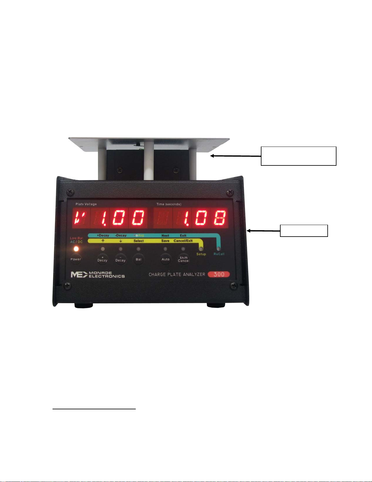
Section 3
OVERVIEW
The Model 300 is comprised of two major assembles: the ion collecting plate assembly and
the console.
ION COLLECTING
PLATE ASSEMBLY
CONSOLE
Figure 1. Front View and Major Assemblies
Front Panel of the Console
Power Button and Power Indicator
The Power button turns the instrument on and off.
If operating from the AC line
will display “CPA 300”, and then will display the firmware revision numbers of both the
console and the plate assembly, respectively. Then the Model 300 will display the system
prompt, which is “-.-“.
, press and release the Power button to turn on the Model 300. It
7
Page 8

If operating from battery, press the Power button for greater than 3 seconds to turn on the
Model 300. It will display “CPA 300” and then will display the firmware revision numbers of
both the console and the plate assembly, respectively. Then the Model 300 will display the
system prompt, which is “-.-“.
The Model 300 will run on either AC line or battery power. The internal, rechargeable battery
will supply up to 8 hours of operation.
The Power indicator presents one of three colors to indicate power conditions:
Green when the instrument is turned on and receiving power from the AC line.
Amber when the instrument is turned on and operating on battery power.
Red when the instrument is turned on, operating on battery power and the battery
needs to be re-charged.
NOTICE: When unplugging the AC adapter from the console, unplug the adapter from
the console unit before unplugging it from the wall outlet. Otherwise, the Model 300 will
turn off and will not continue to operate on battery power.
Charging the Battery
The Model 300 CPM is designed to be used on a regular basis. If it is not going to be used
for an extended period of time:
1. Leave unit connected to the charger. or
2. Recharge the battery every 60 days. or
3. Recharge the battery and remove one of the leads from the battery, then recharge
battery every 6 months.
Whenever the Model 300 is operated from an AC power source, it is charging the battery.
The display on the front panel of the Model 300 will indicate the battery voltage when the
Model 300 is plugged into an AC power source and is turned off.
The Power indicator is red when the battery needs to be recharged. Recharging the battery
may take up to ten (10) hours for a full charge.
Rear Panel of the Console
AC Power Connection
Connect the AC adaptor to the power jack on the rear panel of the Model 300. Use only the
AC adaptor provided by Monroe Electronics, Inc. for use with the Model 300.
USB Port
This connector is for control and data collection from a computer. Monroe Electronics offers a
program that can be installed on a computer for remote control and data collection.
8
Page 9
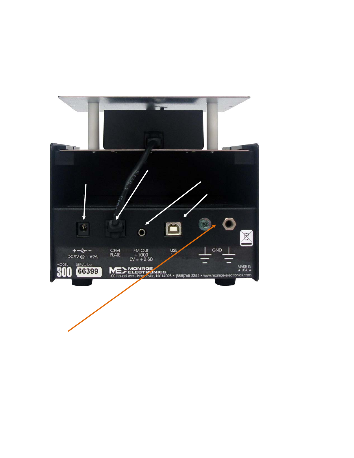
CPM Plate
Connect the ion-collecting plate assembly to this connector using a CAT 5 cable. A 6-inchlong cable is provided for making this connection when the ion-collecting plate assembly is
installed on the top of the console. A 5-foot-long cable is also provided to locate the ioncollecting plate farther from the console.
ION-COLLECTING PLATE CONNECTION
AC POWER CONNCTION
Figure 2. Rear View
Grounding the Model 300
ANALOG OUTPUT
USB PORT
A ground connection is essential for proper measurements of ionization systems. It is
essential to connect the chassis of the console to the facility ground conductor. The AC
adaptor does not provide a ground connection. Connect the Model 300 to ground via either
the banana jack or the green screw on the rear panel of the console.
FM OUT ÷1000 (Fieldmeter Analog Output)
An analog output jack is provided on the rear panel of the console for connection to test
equipment such as chart recorders and oscilloscopes. The output signal is NOT a groundreferenced signal.
9
Page 10
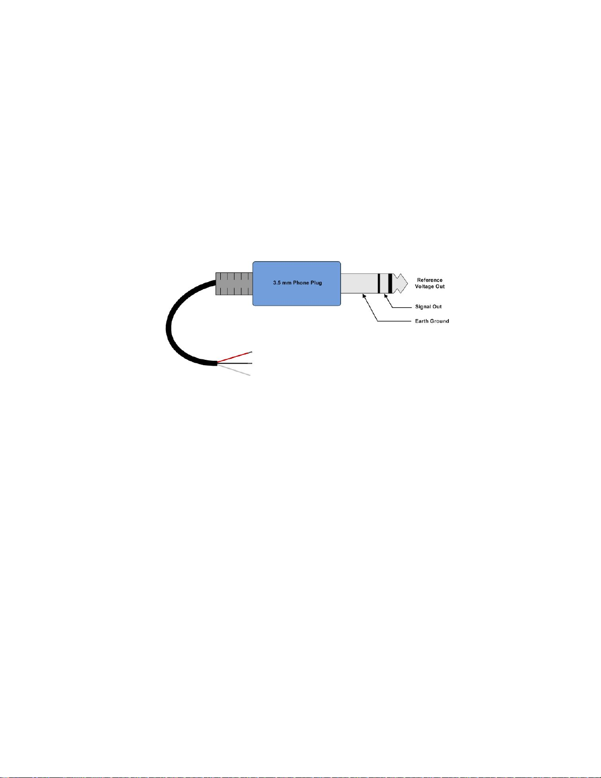
A reference voltage representing zero volts on the ion-collecting plate is provided on one pin
of the connector. This reference voltage is in the range of 2.27V and 2.50V.
The analog output is a unipolar signal representing the plate voltage. The fieldmeter (plate
voltage sensor) output signal appears on another pin of the connector, and is in the range of
±1V from the reference voltage, wherein +1V with respect to the reference voltage
represents +1000V on the ion collecting plate, and -1V with respect to the reference voltage
represents -1000V on the ion collecting plate.
A stereo phone plug is provided. The third terminal is a ground connection.
If connecting the analog output of the Model 300 to an oscilloscope, we recommend
connecting the reference voltage output to one input of the oscilloscope and connecting the
signal output to another input of the oscilloscope, and subtracting the reference output from
the signal output using the math feature or add/invert features of the oscilloscope.
Figure 3. Analog Output Connections
Tripod Mounting
Both the bottom of the console and the bottom of the ion collecting plate are equipped with a
threaded insert for tripod mounting. Thus, either the entire instrument or just the ion
collecting plate can be tripod mounted, depending on your requirements.
Ion Collecting Plate Assembly
Ion Collecting Plate
The Model 300 has a 6 X 6 (15 cm x 15 cm) ion collecting plate assembly (plate assembly)
that can be used in an operational position on the top of the Model 300 console, or it can be
removed and located remotely for testing ionization systems. The plate assembly operational
position atop the console is different from the plate assembly storage position for shipment.
Moving the Plate Assembly from the Storage Position to the Operational Position
As received, the ion collecting plate assembly is stored in the console. (See Figure 4.) The
Model 300 cannot be operated properly when the plate assembly is in this storage position.
10
Page 11
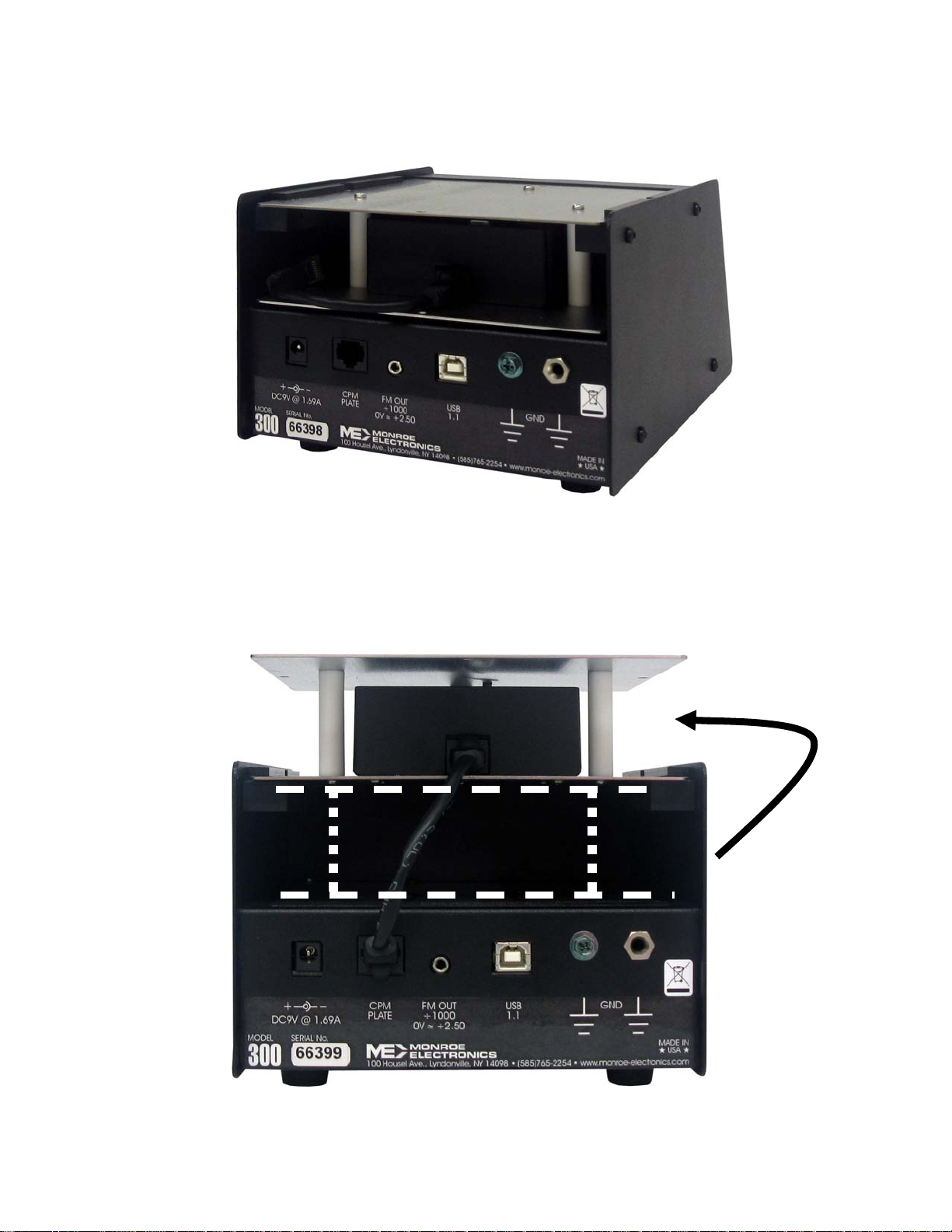
Move the plate assembly from the storage position (See Figure 4.) to the operating position
atop the console unit (see Figure 5). Slide the plate assembly backwards to remove it from
Figure 4. Rear View Showing Plate Assembly Storage Position
11
Page 12

Figure 5. Rear View Showing Plate Assembly In Operational Position On Top of Console Unit
the console unit. Then slide it forward in the guide channel to insert it into the operational
position.
Connect the 6-inch CAT 5 cable between the plate assembly and the console unit.
NOTICE: The power should be off when connecting the plate assembly to
the console.
NOTICE: We recommend returning the plate assembly to the storage
position for transport.
Remote Placement of the Plate Assembly
Turn off the Model 300 before detaching the ion collecting plate from the console.
Disconnect the cable connecting the ion collecting plate to the console.
Slide the ion collecting plate backwards to remove it from the console.
Reconnect the ion collecting plate to the console using the 5-foot-long cable provided.
NOTE: When it is detached from the console, the ion collecting plate maintains a ground
connection via this cable.
NOTE: This cable is a standard CAT 5 cable. Longer cables can be purchased and used
when greater separations between the ion collecting plate and the console are needed.
Navigating the Front Panel
Three operations can be performed from the system prompt (-.-).
1. Perform ionizer tests- initiate tests directly from the system prompt, -.-.
2. Recall test results- press the Shift/Cancel button once to recall test results for the
Model 300.
3. Feature Set Up- press the Shift/Cancel button twice to set up features for the
Model 300.
12
Page 13

Programming (Customizing) the Model 300 for Testing
From the system prompt, -.-, press the Shift/Cancel button until the yellow SETUP indicator
is on, and “SET UP” is displayed.
The yellow button legend becomes the active legend to follow for the buttons.
Use the ↑ and ↓ buttons to scroll through the set up parameters. Once you have reached a
parameter that you want to change, press SELECT to edit its value. EDIT OPT is
momentarily displayed. Then use the ↑ and ↓ buttons to change the value. When done
changing the value, press SAVE to save the new value (SAVE OPT is momentarily
displayed) or CANCEL to exit without saving.
The set up parameters are as follows:
TDLY 0 Test Delay: Set a delay of 0 to 15 seconds after the button is pressed
(for a test) before the test begins. The factory default is 0 seconds.
GPLT DLY Choose an option for grounding the plate:
GPLT DLY ground the plate during the test delay
GPLT <DLY ground the plate prior to the test delay, but not
during the test delay
GPLT DLY> ground the plate after the test delay, but not during
the test delay
The factory default is to ground the plate during the test delay.
VSTP 100 Decay Stop Voltage: Set the desired stop voltage. The stop voltage
can be set to any value from 10V to 990V in 1V increments. The
factory default is 100V.
DLEN 30 Decay Test Length: Set the desired test length for a decay test before
test “times out” and ends the decay test. The decay test length can be
set to any value from 10 to 999 seconds in 1-second increments. The
factory default is 30 seconds.
BLEN 30 Balance (Offset Voltage) Test Length: Set the desired test length for a
balance test before the test “times out” and terminates the balance
test. The balance test length can be set to any value from 0 to 9999
seconds in 1-second increments. Choosing zero (0) as a test length
causes the balance test to run forever. The factory default is 30
seconds.
PKDL 3 Balance Peak Delay: Set the desired time delay after the start of a
balance test before the peak detectors begin to record peak offset
voltages. The balance peak delay can be set to any value from 10 to
300 seconds in 1-second increments. The Balance Peak Delay must
be less (shorter) than the balance test length. The factory default is 3
seconds.
PWR 300 DC Auto Power Off: Set the desired time that the Model 300 will
operate on battery before shutting off. The DC Auto Power Off can be
set to any value from 10 to 9999 seconds in 1-second increments.
Choosing zero (0) as a time causes the Model 300 not to automatically
shut off. The factory default is 300 seconds.
13
Page 14

+++ ---B Automated Test Sequence: Set the desired number and order of tests
for an automated sequence of tests. “+”represents a positive decay
test in the sequence. “-“ represents a negative decay test in the
sequence. “B” represents a balance (offset voltage) test in the
sequence. The choices for an automated test sequence are +-, +-+- +-,
+++---, +-B, +-+-+-B, and +++---B. The factory default is +++---B.
DEFT SET Use this set up option to restore all set up options to their factory
default settings. Press SELECT and then the ↑ and ↓ buttons to
choose “YES” or “NO” to restore the factory defaults edit the value
using. Once the desired value is displayed, press the SAVE button to
save the new value for the feature. SAVE OPT is displayed
momentarily.
CLR DATA Use this set up option to clear all saved test results. Press SELECT
and then the ↑and ↓ buttons to choose “YES” or “NO” to restore the
factory defaults edit the value using. Once the desired value is
displayed, press the SAVE button to save the new value for the
feature. SAVE OPT is displayed momentarily.
Press the Shift/Cancel button again to return to the system prompt, -.-.
14
Page 15

Section 4
OPERATION
Performing Ionizer Tests
Initiate automated test sequences and manual tests directly from the system prompt, -.-.
Selecting a Manual Test: Press +Decay to start a positive discharge test.
Press -Decay to start a negative discharge test.
Press Bal to start a balance (offset voltage) test.
The respective indicator is on and flashing while a test is in
progress.
The respective indicator is on and not flashing when the test is
complete and data is available.
Manual Zero for the Plate: In the event that the instrument does not indicate zero volts for
a balance test (when the ion collecting plate is hard-grounded),
the fieldmeter can be zeroed by pressing the Bal button for >2
seconds. This would be done from the system prompt, -.-.
Selecting an Automated
Test Sequence: Press Auto to run a sequence of discharge and balance tests.
Cancelling a Test: Press Shift/Cancel to cancel a test after it is started.
To View Test Results: Test results are displayed after each test.
For a Decay test, the Decay time is displayed until a new
button is pressed. In the instance when a decay test fails, such
as if there is no ionization to reduce the plate voltage, a failure
message is displayed: either +DCY DFAI or -DCY DFAI,
depending on the polarity of the decay test.
For a Balance test, the display scrolls through the negative
peak voltage (VMIN), the positive peak voltage (VMAX) and the
average voltage (AVG).
Press +Decay, -Decay, Bal or Auto to start a new test or
sequence of tests.
Press Shift/Cancel to return to the system prompt -.-.
Test data can also be viewed using the ReCall feature of the
Model 300.
15
Page 16

Recalling Ionizer Test Results
The test results are saved for the most recent of each positive decay, negative decay,
balance (offset voltage) and auto test. These test results can be recalled by pressing
Shift/Cancel until the green ReCall indicator is on, and RECALL is displayed.
The green button legend becomes the active legend to follow for the buttons.
The indicator corresponding to each type of test (+Decay, -Decay, Balance, and Auto) is on if
there is data available for viewing.
To view the data, press the corresponding button and the data is shown in the alpha-numeric
display.
For recalling balance data
display VMIN (most negative offset voltage), VMAX (most positive offset voltage), AVG
(average offset voltage for the balance test duration), and VSTP (final offset voltage at the
end of the balance test duration).
For recalling automated test sequence data
300 scrolls to display +1D (first +Decay time), +2D (second +Decay time), +3D (third +Decay
time), +AVG (average time for the three +Decay tests), -1D (first -Decay time), -2D (second Decay time), -3D (third -Decay time), -AVG (average time for the three -Decay tests), VMIN
(most negative offset voltage), VMAX (most positive offset voltage), BAVG (average offset
voltage for the balance test duration), and VSTP (final offset voltage at the end of the
balance test duration).
The test data is saved until overwritten by new test data, or until the data is cleared using
CLR DATA in the setup menu.
, each time the Bal button is pressed, the Model 300 scrolls to
, each time the Auto button is pressed, the Model
16
Page 17

Section 5
MAINTENANCE
Precautions
User maintenance should normally be limited to keeping the instrument clean and free from
physical damage. Store the instrument in its protective carrying pouch when not in use.
Cleaning
Fingerprints and other contaminants may be removed from the case with a clean lint-free
cloth dampened in a 70%/30% mix of clean technical grade isopropyl alcohol and de-ionized
water. DO NOT use soap or detergent.
Battery
Battery charge life depends on type of tests being run.
A complete re-charge cycle takes 10 hours with the power off. The battery voltage is
displayed on the console unit when the Model 300 is plugged into an AC power source and is
turned off.
The Model 300 CPM is designed to be used on a regular basis. If it is not going to be used
for an extended period of time:
1. Leave unit connected to the charger. or
2. Recharge the battery every 60 days. or
3. Recharge the battery and remove one of the leads from the battery, then recharge
battery every 6 months.
Calibration
Calibration is not a user function and is beyond the scope of this manual. Calibration
information is available from the factory. Monroe Electronics recommends annual calibration
and/or when the instrument is damaged or repaired or where called for more often by
contract. Monroe Electronics, Inc. offers repair and calibration services for a fee.
Locating the Serial Numbers
Serial number information is useful when consulting with Monroe Electronics or its
distributors for service.
The console and the plate assembly each have a serial number.
The serial number for the console is located on the rear panel.
The serial number for the plate assembly is located on the bottom of the assembly.
17
Page 18

REFERENCES
Documents associated with ionization:
ESD Association Standard — ANSI/ESD STM3.1 –Ionization
ESD Association Advisory – ESD ADV3.2 – Selection and Acceptance of Air Ionizers
ESD Association Standard – ANSI/ESD SP3.3 – Periodic Verification of Air Ionizers
ESD Association Advisory – ESD ADV1.0 – Glossary
These documents are available from:
ESD Association, Inc.
7900 Turin Rd.
Building 3, Suite 2
Rome, NY 13440-2069
Section 6
Phone (315) 339-6937
Fax (315) 339-6793
eosesd@aol.com
http://www.eosesd.org
Monroe Electronics, Inc. does not supply copies of standards or advisories.
18
Page 19

Section 7
APPENDIX I
Bad Battery Message and Resetting the Dead Battery Flag
When operating from the AC line, if the Model 300 has a bad battery, meaning that the Model
300 detects that the battery will not charge above 4 volts within 5 minutes, then a Bad
Battery flag is set and the battery charger will stop trying to charge the battery until the Bat
Battery flag is cleared.
When this condition occurs, the Model 300 displays a BAD BAT message on the front panel
for four (4) seconds. The Model 300 continues to operate properly from the AC line. In the
event that the operator does not see the BAD BAT message when it appears on the front
panel, this message is also displayed when the unit is turned on.
We recommend that the battery be replaced when this message is seen, although the unit
will continue to operate properly under AC power conditions.
Once the battery has been replaced, the Bad Battery flag can be reset by pressing
Shift/Cancel when BAD BAT is displayed during turn on. The Model 300 will display RSET
BATO to indicate that the Bad Battery flag is reset.
19
Page 20

APPENDIX II
CPA300 USB Driver Installation on Windows XP
1) Install the CPA300 pc software on to the PC. You may need to log onto the PC as
Administrator to install the software and the USB driver.
2) Turn on the Model 300. The display shows: [CPA 300], [V1.03 1.02] then the prompt:
[ -.-].
If all these are shown, then go on to Step 3.
If it shows [CPA 300], [COMM ERR], [V1.03 ???], then please check that the
plate cable on the back of the unit is properly connected to the plate assembly.
Power the Model 300 down then up again to see if it is connected. If the problem
persists, report it to Monroe Electronics.
3) Connect the Model 300 to the PC via the USB cable.
4) Run the CPA300 software. It will start searching available comports and list the
CPA300 with the comport if it is found. Selecting the port it will flash green and the
software is ready to communicate with the unit.
If the 300 device is not found, then go on to Windows Start - Control Panel, find the
device, and update the driver:
Control Panel.
It will lead to one of the two views.
Refer to screens below to see which
one apply to you.
Figure 1
20
Page 21

Printers and Other Hardware
Figure 2
System.
Then go on to
Figure 4.
Figure 2a
21
Page 22

System.
Then go on to
Figure 4.
Figure 3
22
Page 23

Hardware
Figure 4
23
Page 24

Device Manager
Figure 5
24
Page 25

Double click on the
SERIAL DEMO
(CPA300-USB), or
right click on it and
select Properties.
Figure 6
25
Page 26

Reinstall Driver
Figure 7
Install from a list or specific
location
Figure 8
26
Page 27

1) Click Include this location in the
search.
2) Then Browse to the 300 software and
USB location. By default, it is in:
C:\Monroe-Electronics\CPA300\USBDrivers
3) Click Next.
Figure 9
27
Page 28

Select USB to UART
Then click Next
Figure 10
Continue Anyway
Figure 11
28
Page 29

Well done if you get to this
page.
Click Finish to close it.
Figure 12
If the driver is updated successfully,
the Device Manager page will show
the USB to UART icon for the 300
USB. It is on Com11 in this example.
Figure 13
Power up the Model 300. You should see the system prompt, -.-, without showing “COMM
ERR”.
Run the 300 PC software, or click on the Connection. It will search for the comport and the
devices. Select the comport that labeled with CPA-300. Then click the [Select highlighted
comport and exit].
29
Page 30

Figure 14
The PC is now connected to the 300 via USB:
If it found the comport, but no CPA300 attached to it, then please try again from step 2.
30
Page 31

APPENDIX III
CPA300 USB Driver Installation on Windows 7
1) Install the CPA300 pc software on to the Win7 PC. You may need to log onto the PC as
Administrator to install the software and the USB driver.
2) Turn on the CPA300 unit, the display shows: [CPA 300], [V1.03 1.02], then the system
prompt, [-.-].
If all these are shown, then go on to Step 3.
If it shows [CPA 300], [COMM ERR], [V1.03 ???], then please check that the plate
cable on the back of the unit is properly connected to the plate assembly. Power the
Model 300 down and then up again to see if it is connected. If a problem persists,
report it to Monroe Electronics.
3) Connect the Model 300 to the PC via the USB cable.
4) Run the CPA300 software. It will start searching available comports and list the CPA300
with the comport if it is found. Selecting the port. It will flash green and the software is
ready to communicate with the unit.
If the 300 device is not found, then go on to Windows Start - Control Panel, find the
device, and update the driver:
Control Panel.
It may lead to one of the two pages.
Refer to the following screens to see
which one apply for you.
Figure 1
31
Page 32

View devices and printers
Figure 2
Double click on the
SERIAL DEMO
(CPA300-USB), or
right click on it and
select Properties. Go on
to Figure 5.
Figure 3
32
Page 33

Or from Windows – Start – Control Panel
Device Manager
Figure 4
Double click on the
SERIAL DEMO
(CPA300-USB), or
right click on it and
select Properties.
Figure 5
33
Page 34

Hardware
Properties
Figure 6
34
Page 35

Change settings
Figure 7
35
Page 36

Update Driver
Figure 8
Browse my computer for
driver software
Figure 9
36
Page 37

Browse to the 300 software and USB location.
By default, it is in:
C:\Monroe-Electronics\CPA300\USB-Drivers
Then click Next.
Figure 10
Install
Figure 11
37
Page 38

After the driver is updated successfully,
the Devices and Printers page will show
the USB to UART icon for the 300 USB.
It is on Com6 in this example.
Figure 12
Run the 300 PC software again, and the 300 is power up to the prompt, -.-, without showing
“COMM ERR”.
The Model 300 software will search for the comport and the devices. Select the comport with
CPA-300, then click the [Select highlighted comport and exit].
Figure 13
Now the PC is connected to the 300 via USB.
38
Page 39

If it found the comport, but no CPA300 attached to it, please try again from step 2.
39
Page 40

APPENDIX IV
CPA300 USB Driver Installation on Windows 8
1) Install the CPA300 pc software on to the PC. You may need to log on to the PC as
Administrator to install the software and the USB driver.
2) Turn on the CPA300 unit. The display shows: [CPA 300], [V1.03 1.02] then the prompt,
-.-.
If all these are shown, then go on to Step 3.
If it shows [CPA 300], [COMM ERR], [V1.03 ???], then please check that the plate cable
on the back of the unit is properly connected to the plate assembly. Power the Model 300
down, and then up again to see if it is connected. If the problem persists, report it to
Monroe Electronics.
3) Connect the Model 300 to the PC via the USB cable.
4) Run the CPA300 software. It will start searching available comports and list the CPA300
with the comport if it is found. Selecting the port it will flash green and the software is
ready to communicate with the unit.
If not found, then go on to Control Panel, find the device, and update the driver.
Click the down arrow
40
Page 41

Control Panel
Select Hardware and Sound:
Under Hardware and Sound,
click View devices and
printers
41
Page 42

Double click on the SERIAL DEMO
with the yellow mark. Or right click on it,
and select Properties.
Double click on the SERIAL DEMO, or right click on it select Properties
Hardware tab
42
Page 43

Properties
Properties:
Change settings
Change settings:
43
Page 44

Update Driver
Update Driver
Browse my computer:
Browse my computer
for driver software
44
Page 45

Browse to the 300 software and USB
location. By default, it is in: C:\MonroeElectronics\CPA300\USB-Drivers
Browse and enter the 300 USB-Driver location, then Next:
Install:
Install
45
Page 46

After the driver is updated successfully, the
Devices and Printers page will show the
USB to UART icon for the 300 USB. It is on
Com3 in this example.
Run the Model 300 PC software again. The Model 300 is powered up to the prompt, “-.-“,
without showing “COMM ERR”. The Model 300 software will search for the comport and the
devices. Select the comport with CPA-300, then click the [Select highlighted comport and
exit]. The PC is now connected to the Model 300 via USB.
46
Page 47

APPENDIX V
Error Messages
Error Messages on RECALL test data:
----------------------------------
+DCY CFAI +decay charge failed.
-DCY CFAI -decay charge failed.
The Model 300 charged for 30 seconds and the plate
voltage did not reach to 1100v.
+DCY DFAI +decay failed.
-DCY DFAI -decay failed.
It is caused by one of the following:
1) After charging to 1100v, the decay test ran for 1
minute without getting to 1000v, and the decay
timer did not start.
2) After the decay timer started at 1000v, the decay
test ran to the maximum decay length and the
voltage did not reached to the V stop setting
(timed out).
+AVG FAIL
-AVG FAIL The decay average fails to calculate on an auto
sequence test when one or more decay tests fails.
Error Message during operation:
-------------------------------
COMM ERR The plate isn't connected to the base unit. Check
connection.
CHRG CFAI Charge failed.
On a decay test, the Model 300 charged for 30
seconds without getting to 1100v.
DCAY DFAI Decay failed. Refer to above "DCY DFAI" for the
cause.
BAD BAT Bad battery
When the Model 300 is plugged in to AC power, the
battery charger starts. If charging for 5 minutes
and the battery voltage is still below 4v, then the
Bad Battery flag is set and the charger stops
charging until the flag is cleared. The device is
47
Page 48

still functional with AC supply. Replacing the
battery is recommended.
RSET BAT0 Reset Bad Battery Flag.
When the Model 300 is powered up and the Bad Battery
flag is set, it displays "BAD BAT" for 4 seconds.
During this time, pressing the Shift key will reset
the Bad Battery flag. If successful, it will show:
"RSET BAT0".
BAT LTMP Battery at low temperature <4c environment
BAT HTMP Battery at high temperature >50c environment
When in AC on power up, if the battery temperature
sensor detects that the temperature is below 4c or
above 50c, the Model 300 will not charge the battery
until the temperature is back to within 4c - 50c.
There is no need to take any action, the Model 300
continues to function as normal. The message will
not be shown when the temperature is back within
normal range, and then the charging resumes.
48
Page 49

APPENDIX VI
49
Page 50

WARRANTY
Monroe Electronics, Inc., warrants to the Owners, this instrument to be free from defects in
material and workmanship for a period of two years after shipment from the factory. This
warranty is applicable to the original purchaser only.
Liability under this warranty is limited to service, adjustment or replacement of defective parts
(other than tubes, fuses or batteries) on any instrument or sub-assembly returned to the
factory for this purpose, transportation prepaid.
This warranty does not apply to instruments or sub-assemblies subjected to abuse, abnormal
operating conditions, or unauthorized repair or modification.
Since Monroe Electronics, Inc. has no control over conditions of use, no warranty is made or
implied as to the suitability of our product for the customer’s intended use.
THIS WARRANTY SET FORTH IN THIS ARTICLE IS EXCLUSIVE AND IN LIEU OF ALL
OTHER WARRANTIES AND REPRESENTATIONS, EXPRESS, IMPLIED OR STATUTORY
INCLUDING BUT NOT LIMITED TO THE IMPLIED WARRANTIES OF MERCHANTABILITY
AND FITNESS. Except for obligations expressly undertaken by Monroe Electronics, in this
Warranty, Owner hereby waives and releases all rights, claims and remedies with respect to
any and all guarantees, express, implied, or statutory (including without limitation, the implied
warranties of merchantability and fitness), and including but without being limited to any
obligation of Monroe Electronics with respect to incidental or consequential damages, or
damages for loss of use. No agreement or understanding varying or extending the warranty
will be binding upon Monroe Electronics unless in writing signed by a duly authorized
representative of Monroe Electronics.
In the event of a breach of the foregoing warranty, the liability of Monroe Electronics shall be
limited to repairing or replacing the non-conforming goods and/or defective work, and in
accordance with the foregoing, Monroe Electronics shall not be liable for any other damages,
either direct or consequential.
50
Page 51

RETURN POLICIES AND PROCEDURES FACTORY REPAIR
Return authorization is required for factory repair work. Material being returned to the factory
for repair must have a Return Material Authorization number. To obtain an RMA number,
call 585-765-2254 and ask for Customer Service.
Material returned to the factory for warranty repair should be accompanied by a copy of a
dated invoice or bill of sale, which serves as a proof of purchase for the material. Serial
numbers, date codes and tamper proof stickers on our products also serve to determine
warranty status. Removal of these labels or tags may result in voiding a product’s warranty.
Repairs will be returned promptly. Repairs are normally returned to the customer by UPS
within 10 to 15 working days after receipt by Monroe Electronics, Inc. Return (to the
customer) UPS charges will be paid by Monroe Electronics on warranty work. Return (to the
customer) UPS charges will be prepaid and added to invoice for out-of-warranty repair work.
RETURN OF REPAIRED ITEMS:
Factory repairs will be returned to the customer by the customer’s choice of FedEx, DHL or
UPS. Warranty repairs will be returned via UPS ground. The customer may request
accelerated shipping via the previous mentioned carriers for both warranty and non-warranty
repairs. NOTE: Accelerated transportation expenses for all factory repairs will always be at
the expense of the customer despite the warranty status of the equipment.
FACTORY REPAIRS TO MODIFIED EQUIPMENT:
Material returned to the factory for repair that has been modified will not be tested unless the
nature and purpose of the modification is understood by us and does not render the
equipment untestable at our repair facility. We will reserve the right to deny service to any
modified equipment returned to the factory for repair regardless of the warranty status of the
equipment.
51
 Loading...