

Page 1

Instruction Manual
for
Surface Resistance Test Kit
Model 292
Printed in USA Copyright Monroe Electronics, Inc.
Specifications subject to change without notice.
100 Housel Ave PO Box 535 Lyndonville NY 14098 585-765-2254 fax: 585-765-9330 monroe-electronics.com
Page 1 of 9
P/N 0340180
10/04/02
Page 2

Warranty
Monroe Electronics, Inc., warrants to the Owners, this instrument to be free from defects in material and
workmanship for a period of two years after shipment from the factory. This warranty is applicable to the
original purchaser only.
Liability under this warranty is limited to service, adjustment or replacement of defective parts (other than
tubes, fuses or batteries) on any instrument or sub-assembly returned to the factory for this purpose,
transportation prepaid.
This warranty does not apply to instruments or sub-assemblies subjected to abuse, abnormal operating
conditions, or unauthorized repair or modification. Since Monroe Electronics, Inc. has no control over
conditions of use, no warranty is made or implied as to the suitability of our product for the customer’s intended
use.
THIS WARRANTY SET FORTH IN THIS ARTICLE IS EXCLUSIVE AND IN LIEU OF ALL OTHER
WARRANTIES AND REPRESENTATIONS, EXPRESS, IMPLIED OR STATUTORY INCLUDING BUT NOT
LIMITED TO THE IMPLIED WARRANTIES OF MERCHANTABILITY AND FITNESS. Except for obligations
expressly undertaken by Monroe Electronics, in this Warranty, Owner hereby waives and releases all rights,
claims and remedies with respect to any and all guarantees, express, implied, or statutory (including without
limitation, the implied warranties of merchantability and fitness), and including but without being limited to any
obligation of Monroe Electronics with respect to incidental or consequential damages, or damages for loss of
use. No agreement or understanding varying or extending the warranty will be binding upon Monroe
Electronics unless in writing signed by a duly authorized representative of Monroe Electronics.
In the event of a breach of the foregoing warranty, the liability of Monroe Electronics shall be limited to
repairing or replacing the non-conforming goods and/or defective work, and in accordance with the foregoing,
Monroe Electronics shall not be liable for any other damages, either direct or consequential.
Return Policies and Procedures
FACTORY REPAIR:
Return authorization is required for factory repair work. Material being returned to the factory for repair must
have a
Customer Service.
Material returned to the factory for warranty repair must be accompanied by a copy of a dated invoice or bill of
sale, which serves as a proof of purchase for the material. Repairs will be returned promptly. Repairs are
normally returned to the customer by UPS within ten working days after receipt by Monroe Electronics, Inc.
Return (to the customer) UPS charges will be paid by Monroe Electronics on warranty work. Return (to the
customer) UPS charges will be prepaid and added to invoice for out-of-warranty repair work.
EXPEDITED FACTORY REPAIR:
All material returned to the factory by air or by an overnight service will be expedited. Expedited factory repairs
will be returned to the customer by the same mode of transportation by which the material was returned to the
factory for repair (i.e., material returned to the factory by an overnight service will be returned to the customer
by an overnight service).
NOTE: Return (to the customer) transportation expenses for expedited factory repairs will always be at the
expense of the customer despite the warranty status of the equipment.
FACTORY REPAIRS TO MODIFIED EQUIPMENT:
Material returned to the factory for repair that has been modified will be not tested unless the nature and
purpose of the modification is understood by us and does not render the equipment untestable at our repair
facility. We will reserve the right to deny service to any modified equipment returned to the factory for repair
regardless of the warranty status of the equipment
Return Material Authorization number. To obtain an RMA number, call 585-765-2254 and ask for
.
Page 2 of 9
Page 3

Specifications
Range: 1.0 x 10³ to 1 x 10¹² @ 10V
1.0 x 10
Accuracy: 1.0 x 10³ to 9.9 x 10⁶ @ 10V 10% of reading at 70-800F; 15–60% RH
1.0 x 10
Open Circuit Voltages: 10 and 100 volts 3%
Electrification Period: 15 seconds
Temperature Accuracy: 5 degrees F and 3 degrees C Typ.
Relative Humidity: Range from 5% - 95%; 10% Typ.
Power: Two - Alkaline AA batteries
Battery Life: approximately 1500 measurements.
Meter Jacks: Left jack on meter accepts a 3.5 mm plug
Right jack on meter accepts a standard banana plug
Test Leads: Black lead terminated with a 3.5 mm plug one end and a standard banana plug on
the other
White lead terminated with a standard banana plus both ends
External Electrodes: Two NFPA-99 5-pound electrodes ( 80 oz.) 2oz with Shore A (IRHD) 50 – 70
durometer conductive pads that comply with EOS/ESD S4.1
7
to 1 x 10¹² @ 100V
7
to 1 x 10¹² @ 100V 10% of reading at 70-800F; 15–60% RH
Resistivity Electrodes: Parallel conductive silicone rubber electrodes 4 inches long and spaced 4
inches apart mounted onto an adapter sled
Meter Weight: 15.5 oz. With out adapter; 23 oz. with adapter
Dimensions: 8” L x 4.3” W x 1.6” H
Kit includes:
Meter
Protective carrying case
Test leads
Two NFPA-99 5-pound electrode weights
Two AA Alkaline batteries
Operator’s Manual
Resistivity adapter sled is optional and must be ordered separately.
Specifications are subject to change without notice.
Page 3 of 9
Page 4

Description
Monroe Model 292 Digital Surface Resistance Test Kit is a portable, versatile, instrument designed
to accurately measure resistance between two points (RTT), surface to ground (RTG), and surface
resistivity in accordance with EOS/ESD Association standard S-4.1. In addition, the meter measures
ambient temperature and relative humidity.
The Surface Resistance Meter is designed to make measurements in accordance with specified test
methods on:
Work surfaces – ANSI/ESD S4.1 Work surfaces – Resistance Measurements
Floors – ANSI/ESD S7.1 – Resistive Characterization of Materials Floor Materials
Footwear – ANSI/ESD S9.1 – Footwear- Resistive Characterization
Garments – ANSI/ESD STM 2.1 Garments
Seating –ANSI/ ESD STM 12.1 Seating – Resistive Measurement
Floor/Footwear – ANSI/ESD STM 97.1 Floor Materials and Footwear Resistance
Measurement in Combination with a Person
Workstations – ANSI/ESD-AVD 53.1 ESD Protective Workstations
Electrification Period
The 292 Surface Resistance Test Kit provides the proper electrification period of 15 seconds
per ANSI/ESD S4.1.
Liquid Crystal Display (LCD)
A 3.5 digit 9/16” high, liquid crystal display provides easy to read measurements directly from the
meter. No interpretations or calculations are required. Surface resistance ohm values are
expressed by the LCD and an illuminated LED which indicates the reading’s exponential value. For
example: if the LCD reads 6.52 and the LED adjacent to the 8 is illuminated, the measurement is
6.52 x 10
8
ohms or 652,000,000 ohms.
If the surface resistance is over 1012 ohms, the following will appear on the LCD display:
“1._ _ _ _” indicating that the reading exceeds the unit’s capabilities.
LED Displays
Surface resistance exponents are displayed via 12 light emitting diodes (< 10
color coded for quick check recognition. Five additional Function LEDs, located to the right of the
red test button, identify the measurement taken when lit. When battery voltage drops to
approximately 2 volts, one of the Function LEDs will begin to flash, indicating the need to replace the
batteries.
Test Button
The red test button activates electrical power to the meter. When the test button is depressed and
held the exponent LED is lit immediately. During the meter’s electrification period the LCD will
display the temperature in Fahrenheit for 5 seconds, the temperature in Celsius for 5 seconds, then
the Relative Humidity as a percent for 5 seconds, and then the surface resistance measurement in
decimal notation.
3
- >1012). LEDs are
Page 4 of 9
Page 5

Override Test Range Voltage Button
The button is a switch, which if depressed will override automatic voltage selection and test will be
performed at 10 volts regardless of resistance level.
When in the “up” or Auto position, during resistance portion of test, meter will automatically switch to
the correct voltage for the resistance range. A function LED will light to indicate selected voltage.
Conductive material 10
5
ohms or less is measured at 10 volts. Dissipative material 106 ohms or
greater is tested at 100 volts.
Jacks
The left hand jack on the meter accepts a shielded 3.5mm plug. The right hand jack accepts a
standard banana plug.
Test Leads
One end of the black test lead provided is terminated with a 3.5mm plug and fits the left meter jack.
The 3.5mm plug is shielded per ESD S4.1 (Refer to RTG test procedure later in this manual.) The
other end of the black test lead and both ends of the white test leads are terminated with a standard
banana plug.
Battery Replacement
The battery compartment is located in the bottom end of the unit. Depress the two buttons on the
sides of the bottom end cap and remove cap. Press on the right edge of the protruding battery door
to unlatch it and swing the door open. Observe polarity and carefully replace the batteries with
alkaline Type AA. Polarity must be correct or damage may occur. Close battery door and reinstall
bottom end cap onto meter case.
Cleaning and Maintenance
Work surfaces or material to be tested should be cleaned prior to testing to ensure that surface dirt
and contamination do not affect the test results. Periodically clean the two 5-pound conductive
rubber probe electrode surfaces. Use solvent free rubber cleaners. We recommend using an antistatic cleaner or Stat Wipes, pre-saturated cleaning wipes. Make sure the surface is dry before
testing.
The 292 Surface Resistance Test Kit requires little maintenance with no user serviceable parts. If
your meter requires service beyond cleaning the electrodes or changing the batteries, please contact
the factory.
Calibration
Monroe Electronics instruments are factory-calibrated prior to shipment. Recalibration should be
performed annually, or more frequently if specified by contract or company policy. Your instrument
should also be recalibrated any time it has been repaired or tampered with. We are happy to
recalibrate your instrument for you at a reasonable cost, or provide information and procedures on
calibration upon request.
Page 5 of 9
Page 6

Literature References
Monroe Electronics recommends that anyone using Model 292 read the following standards from the
ESD Association:
EOS/ESD-ADV1.0 – Glossary of Terms
EOS/ESD-S4.1 – Work surfaces
EOS/ESD-S6.1 – Grounding
ESD-S7.1 – Floor Materials
EOS/ESD-S11.11 – Surface Resistivity
These documents are available directly from the ESD Association
7900 Turin Road
Suite 4
Rome NY 13440-2069
(315) 339-6937
General Guidelines for Testing
Use both 5-pound electrodes for RTT (Resistance between two points) testing.
Use one 5-pound electrode and one lead to a groundable point for RTG (Resistance to
Ground) testing.
Use the optional resistivity adapter sled (removing leads and electrodes) for Resistivity
measurements.
Make sure that the item being measured is electrically isolated (i.e. placed on an insulative
surface) as the meter will measure the lower resistance path.
Make sure that the test leads are separated or the meter may measure the lower resistance
path
When using the 5-pound electrodes:
o Place the electrodes no closer than 2 inches from edge of surface being measured.
o Place the electrodes no closer than 3 inches to any groundable point
o Preferred placements include: most commonly used surface portion, most worn,
center, and furthest from a groundable point.
o For RTG, connect the sensing lead with shielded plug to the groundable point.
If the surface has sections (like tile flooring or garment panels), for RTT place the electrodes
on different sections.
Page 6 of 9
Page 7

RTT - Measuring Resistance Between Two Points
Point to point surface resistance measurements are made using the meter with both of the 5-pound
weight electrodes. This test determines the resistance two points independent of a ground point.
To perform surface resistance tests you must first determine what test procedure to use. The test
procedure helps you determine the proper preparation of the material to be tested and the spacing of
the weights. Once the testing parameters are determined proceed with set up for point-to-point
testing.
Connect the test leads to the meter and the 5-pound electrodes in a set up similar to the one
shown above.
Place both electrodes on the material at positions determined by the procedure selected. Set
the meter to the required test voltage as specified in the test procedure and the resistance of
the material.
Press and hold the red test button for at least 15 - 20 seconds. The LCD expresses surface
resistance ohm values and an illuminated LED indicates the reading’s exponential value.
Page 7 of 9
Page 8
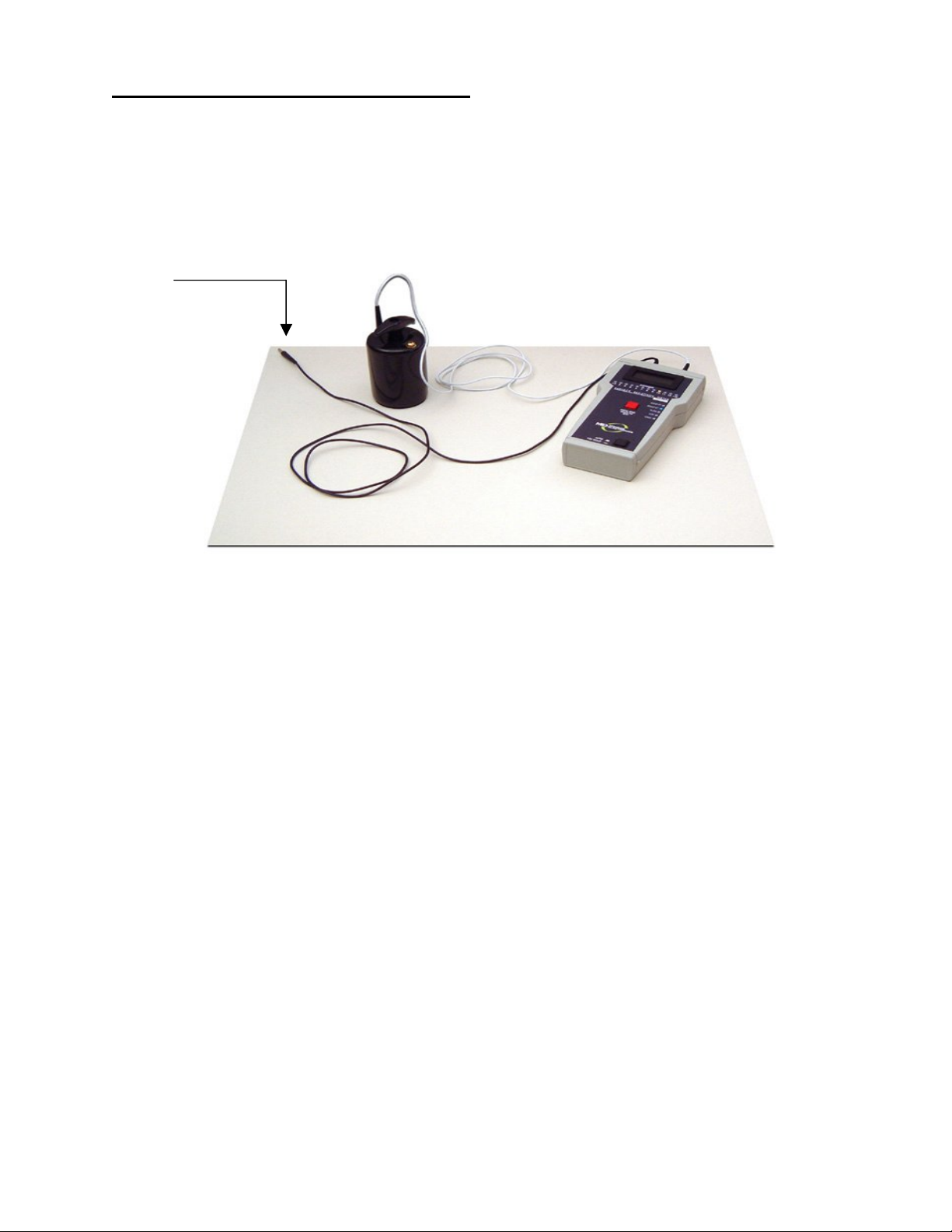
RTG – Resistance to Ground Measurements
Resistance to ground measurements indicate the surface resistance between selected locations on
a work surface and a groundable point or points. Ground points are usually in the form of snaps
installed on the material so that the material can be grounded via ground cords.
The charge dissipative rate of all ESD protective materials is related directly to electrical resistance
to ground. When making Resistance-to-Ground measurements follow this procedure:
To
GND
Connect the black test lead to the left hand jack on the meter and to ground.
Connect the white test lead to the right hand jack on the meter and to the 5-pound electrode.
Place the electrode on the material at the position specified by the procedure selected. Set
the meter to the desired voltage range. Be sure to keep the cords separated in order to
prevent false readings, especially when testing high resistance materials.
Press and hold the red test button for at least 15 - 20 seconds. The LCD expresses surface
resistance ohm values and an illuminated LED indicates the reading’s exponential value.
Repeat the procedure to measure other points on the material under test.
Page 8 of 9
Page 9
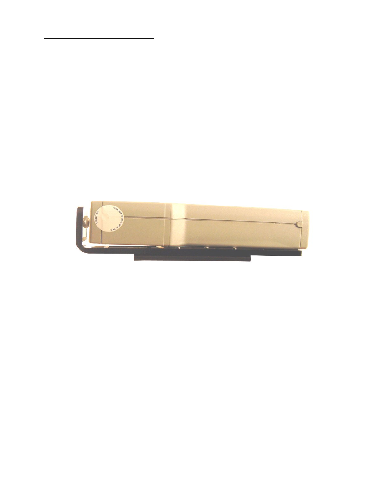
Surface Resistivity Measurements
To make surface resistivity measurements the user must also have the optional resistivity adapter
sled, Model 292/41.
The meter attaches easily to an optional resistivity adaptor sled. Parallel silicone rubber electrodes
provide for direct measurement of surface resistivity. No conversion is required with the Surface
Resistivity Test Kit. The electrode geometry is 1 square resulting in a reading expressed in
ohms/square.
Disconnect the test leads and electrodes from the meter.
Mount the meter securely onto the adapter sled.
Firmly press the sled’s parallel electrodes onto the surface of the material to be tested, at the
position specified by the procedure selected.
Press and hold the red test button for at least 15 - 20 seconds. The LCD expresses surface
resistivity in ohms/square and an illuminated LED indicates the reading’s exponential value.
Page 9 of 9
 Loading...