

Page 1
Installation and Operation Manual
30T
E33T C-Store
Convection Oven
SERIES
238681-1
Page 2
Australia
www.moffat.com.au
New Zealand
www.moffat.co.nz
www.turbofanoven.com
Australia
Moffat Pty Limited
740 Springvale Road
Mulgrave, Victoria 3170
Telephone 03-9518 3888
Facsimile 03-9518 3833
nsw@moffat.com.au
New Zealand
Moffat Limited
16 Osborne Street
Christchurch 8011
Telephone 03-389 1007
Facsimile 03-389 1276
sales@moffat.co.nz
Designed and manufactured by
ISO9001
All Turbofan products are designed and
manufactured by Moffat using the
internationally recognised ISO9001
quality management system, covering
design, manufacture and final inspection,
Ensuring consistent high quality at all
times.
In line with policy to continually develop
and improve its products, Moffat Limited
reserves the right to change specifications
and design without notice.
The reproduction or copying of any part of this manual by any means whatsoever is strictly forbidden unless authorized previously in writing
by the manufacturer.
In line with policy to continually develop and improve its products, Moffat Ltd. reserves the right to change the specifications and design
without prior notice.
© Copyright Moffat Ltd. April 2015.
Page 3

Contents List
E33T Turbofan Convection Oven.
E33T C-Store Convection Oven
Introductio n ............................................................................................................................... 3
Safety Information
Specificati ons ............................................................................................................................. 4
Installation ................................................................................................................................. 5
Installation Requirements
Unpacking
Location
Clearances
Stand Mounted Ovens
Electrical Connection
Water Connection
Recommended Water Specifications
Positioning and Levelling of Oven
Initial Start-Up
Commissioning
Operation - Oven Mode .............................................................................................................. 7
Oven Mode
Control OFF
Control ON
Pre-Heating
Select Shelf
Select Product
Load Tray(s)
Program Start
Done - Time Up
Return to Step 4
Manager Mode - Recipe Programming .................................................................................... 9
Entering Recipe Programming
Enter Manager Mode
Enter Passcode
Enter Recipe Programming
Recipe Editing
Recipe Naming
Recipe Image
Recipe Category
Set Number of Shelves
Set Recipe Time and Temperature
Page 4

Contents List
Manager Mode - Settings ......................................................................................................... 13
Selecting Manager Mode
Control ON
Enter Passcode
Manager Screen #1
Recipe Programming
Copy Recipes to USB
Copy Recipes from USB
Preheat Options
Manager Screen #2
Piezo Volume Adjustment
Cook Done Beep On/Off Setting
Ready Beep On/Off Setting
Keypress Feedback Enable/Disable
Manager Screen #3
Manager Passcode Enable/Disable
Screen Brightness Adjust
Screen Auto Dim Setting
Recipe Image Maintenance
Manager Screen #4
Change Passcode
Energy Saving Temperature Setback Options
Auto Start Setting Options
System Information
Manager Screen #5
Real Time Setting
Date Settings
Language Selection
Temperature Unit Selections °C / °F
Manager Screen #6
Touch Screen Calibration
Cleaning and Maintenance ..................................................................................................... 18
Cleaning Guidelines
Oven Cleaning
Periodic Maintenance
Electrical Schematics ............................................................................................................. 20
Electrical Schematic E33T C-Store (High Speed Option - 2 Speed Fan Motor)
Electrical Schematic E33T C-Store (Standard 2 Speed Fan Motor)
Replacement Parts List .......................................................................................................... 22
Page 5
Introduction
Before using your new oven, please read this instruction manual
carefully, pay particular attention to any information labelled
‘WARNING’, ‘CAUTION’, ‘IMPORTANT’ or ‘NOTE’ in this
manual.
Warning
Caution
If you are unsure of any aspect of the installation, instructions or
performance of your oven, contact your TURBOFAN dealer promptly.
In many cases a phone call could answer your question.
Should you contact your TURBOFAN dealer on any matter concerning this oven, please have the information provided opposite, readily
available.
I
NDICATES A HAZARDOUS SITUATION
WHICH, IF NOT AVOIDED, WILL RESULT IN
DEATH OR SERIOUS INJURY.
I
NDICATES A HAZARDOUS SITUATION
WHICH, IF NOT AVOIDED, WILL RESULT IN
MINOR OR MODERATE INJURY.
This manual must be kept by the owner for future reference.
A record of
Number of the oven
below.
Date of Purchase, Date of Installation
should be recorded in the area provided
and
Serial
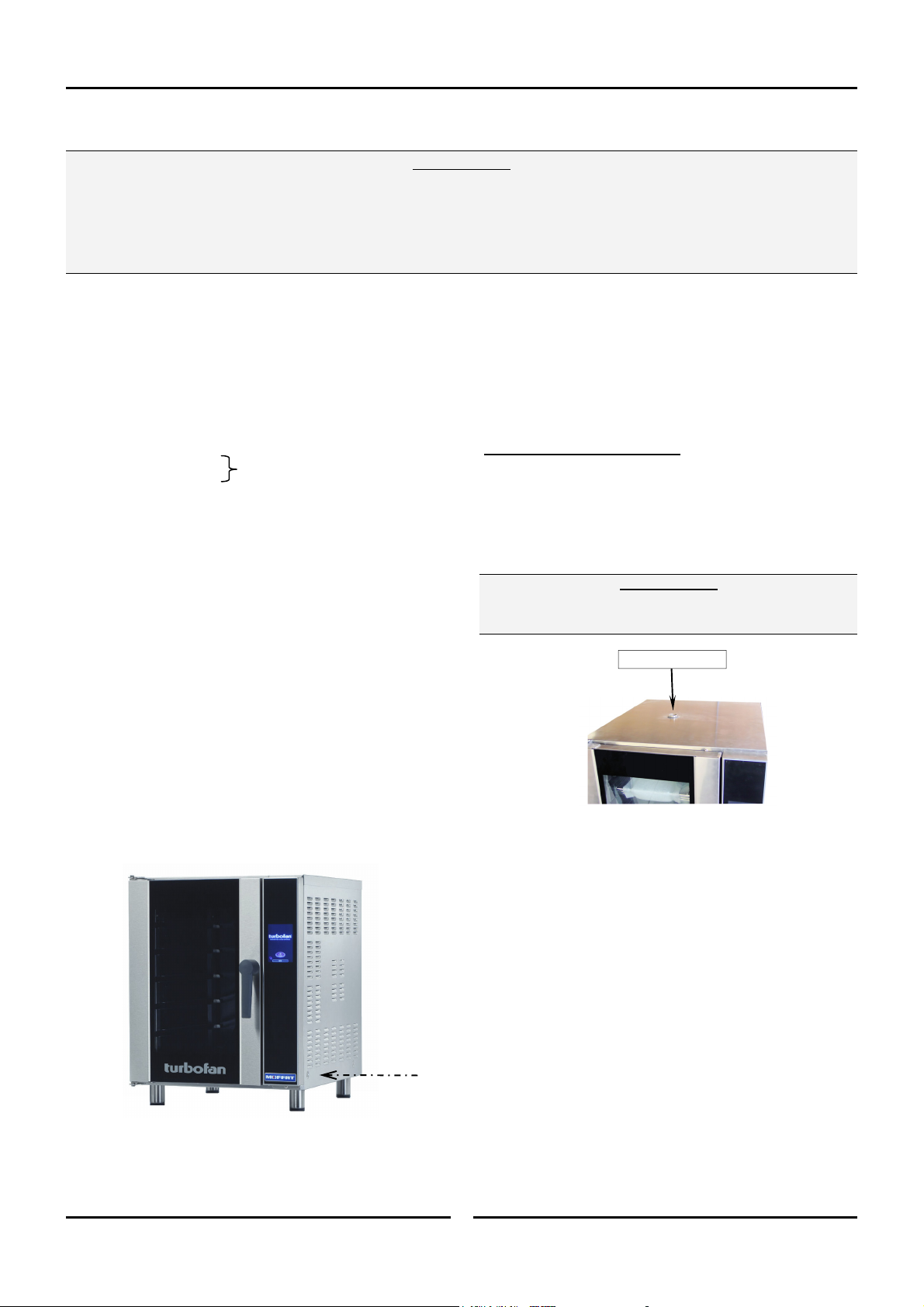
The serial number of this oven can be found on the
Technical Data Plate located on the front right hand side
panel, see diagram in ‘Installation Section’.
Model Number:
Serial Number:
Dealer:
Service Provider:
Date Purchased:
Date Installed:
Safety Information
For your safety, please pay attention to the following symbols
marked on the appliance.
- R
ISK OF ELECTRIC SHOCK.
NO USER SERVICEABLE PARTS INSIDE.
UALIFIED SERVICE PERSON ACCESS ONLY.
Q
DISCONNECT FROM POWER BEFORE SERVICING.
3
Page 6
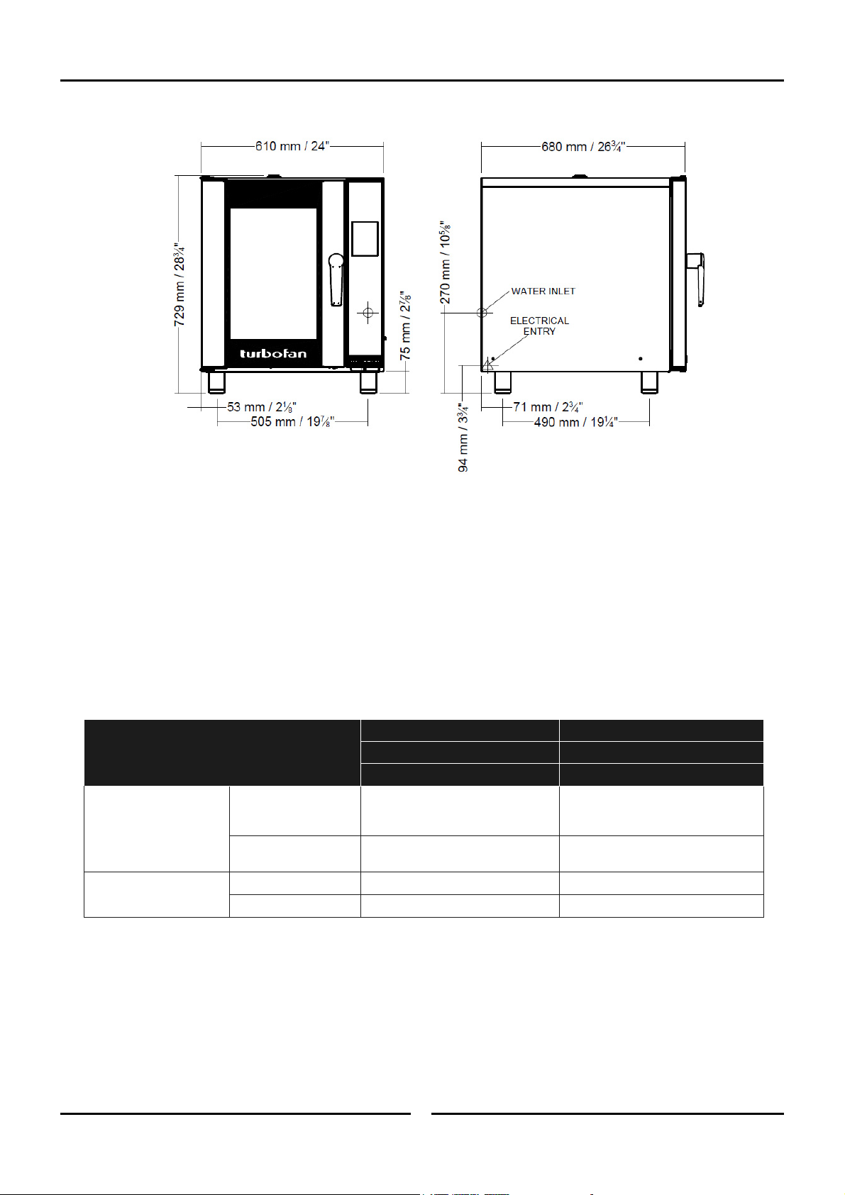
E33T
Specifications
Oven Power Ratings
Oven Tray Details
Water Connection
USA / Canada
208V, 60Hz, 5.4kW.
220 - 240V, 60Hz, 6.0kW.
5 Shelf - 13” x 18” Bun Pan.
Tray Capacity
12” x 20” Steam Pan.
(Optional, 4 Shelf).
Tray Spacing
5 Shelf - 3
4 Shelf - 113mm / 4
1
/3” / 85mm.
Max Water Pressure 80psi / 550kPa.
3
Connection Size
/4” GHT.
4
1
/2”.
Other Markets
220V, 50Hz or 60Hz, 6.0kW.
230 - 240V, 50Hz or 60Hz, 6.0kW.
5 Shelf, 1/1 GN Pan.
(Optional, 4 Shelf).
5 Shelf - 85mm / 3
4 Shelf - 113mm / 4
1
/3”.
1
/2”.
80psi / 550kPa.
3
/4” BSP.
Page 7
Installation Requirements
Installation
Important:
Installation shall comply with local electrical, health and safety requirements.
It is most important that this oven is installed correctly and that oven operation is correct before use.
If you have any questions regarding the proper installation and / or operation of this oven, please contact your local
Turbofan distributor.
Unpacking
1. Remove all packaging and transit protection including all
protective plastic coating from the exterior stainless steel
panels.
2. Check the oven and supplied parts for damage. Report any
damage immediately to the carrier and distributor.
3. Check that the following parts have been supplied with your
oven:-
4 x Leg Adjustable.
Adaptor Brass.
Washer Rubber.
4. Report any deficiencies to the distributor who supplied your
oven.
5. Securely fit the 4 legs supplied with the oven.
6. Check that the available electrical supply is correct to that
shown on the Technical Data Plate located on the front right
hand side panel.
Refer to ‘Specifications’ section, ‘Oven Specifications
Table’ on previous page.
Location
1. Position the oven in its approximate working position.
2. The unit should be positioned so that the control panel and
oven shelves are easily reachable for loading and unloading.
USA / Canada Only.
Clearances
To ensure correct ventilation for the motor and controls, the
following minimum installation clearances are to be adhered to:-
Clearance From Source of Heat.
A minimum distance of 300mm (12”) from the appliance
sides is required.
NOTE: Fixed installations require at least 500mm (20”)
The vent located on the top of the oven must NOT be
obstructed.
Top 200mm / 8”
Rear 50mm / 2”.
Left-hand side 50mm / 2”.
Right-hand side 75mm / 3”.
clearance for service access.
Important:
Oven Vent Location
Stand Mounted Oven
For stand mounted ovens, the oven feet are used to level the oven
on the stand. Refer to the instructions supplied with separately
ordered stands for mounting details.
Technical Data Plate - Data and Location
5
Page 8
Installation
Electrical Connection
T
HIS OVEN MUST BE EARTHED / GROUNDED.
Each oven should be connected to an adequately protected power
supply with an appropriate three wire power cord.
An isolation switch must be mounted adjacent to, but not behind
the oven and must be readily accessible to the operator. This
switch must be clearly marked and readily accessible in case of
fire.
Check the electricity supply is correct to as shown on the
Technical Data Plate on the front right hand corner of the oven
side panel.
NOTE: All electrical connections must only be carried out
1. Remove oven right hand side panel.
2. Bring the supply cable up through the grommet at the back
3. Connect the mains supply to the appropriately marked
Water Connection - Optional
by a suitably qualified person.
of oven and through the compression gland on the electrical
switchgear panel.
terminals on the terminal block.
(Not required for Main Oven Operation)
Warning
Positioning and Levelling of Oven
1. Correctly locate the oven into its final operating position and
using a spirit level, adjust the oven feet so that the oven is
level and at the correct height.
Initial Start-Up
Before using the new oven;
1. When using the oven for the first time, operate oven for
about 1 hour at 200°C / 400°F to remove any fumes or
odours which may be present.
2. Please refer to the Operation Section of this manual for
details on how to correctly operate and shutdown the oven.
Commissioning
Before leaving the new installation;
Check the oven functions in accordance with the operating
instructions specified in the ‘Operation’ section of this manual.
Ensure that the operator has been instructed in the areas of
correct operation and shutdown procedure for the appliance.
NOTE: If it is not possible to get appliance to operate
correctly, turn ‘Off’ power at the mains supply and
contact supplier of this appliance.
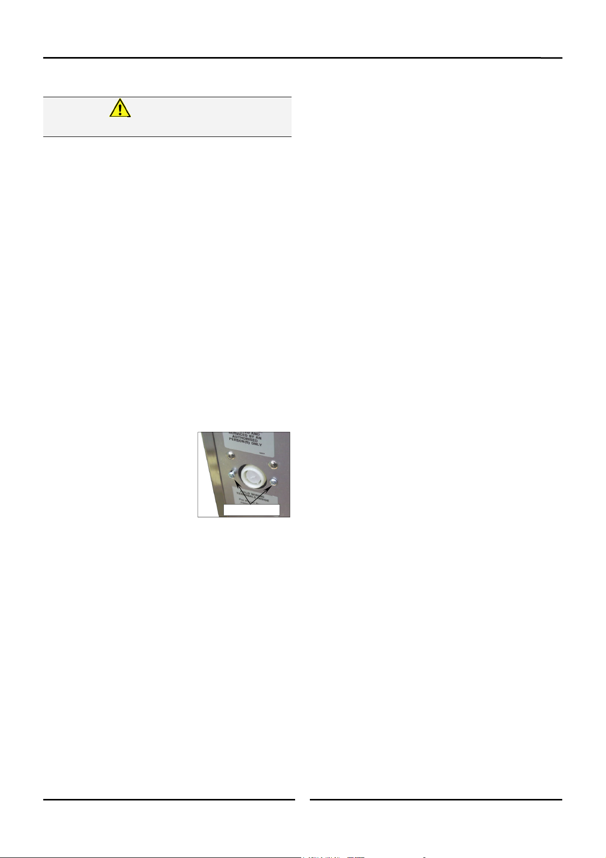
1. If the manual addition of water into the oven for
humidification or steaming effect on baked product is
required, the unit’s water connection can be used.
2. Tighten the 2 screws securing the
water connection to the rear of
the oven. (These have
purposely been left loose to
prevent damage to the water
connection during transit).
3. Connect a cold water supply to the
water inlet (R ¾” Connector) on
the rear, right hand side of the
oven. (USA / Canada only, supplied with ¾” GHT adaptor).
- Max Inlet Pressure 80psi / 550kPa.
4. Turn ‘On’ the water supply and check for leaks.
Recommended Water Specifications
In order to prevent corrosion or scaling in the oven and water
system due to supplying water that is either too soft or too hard,
the following recommendations should be used as a guideline.
Hardness: Between 60 and 90ppm.
PH: Greater than 7.5.
Chlorides: Less than 30ppm.
Tighten Screws.
6
Page 9
Operation - Oven Mode
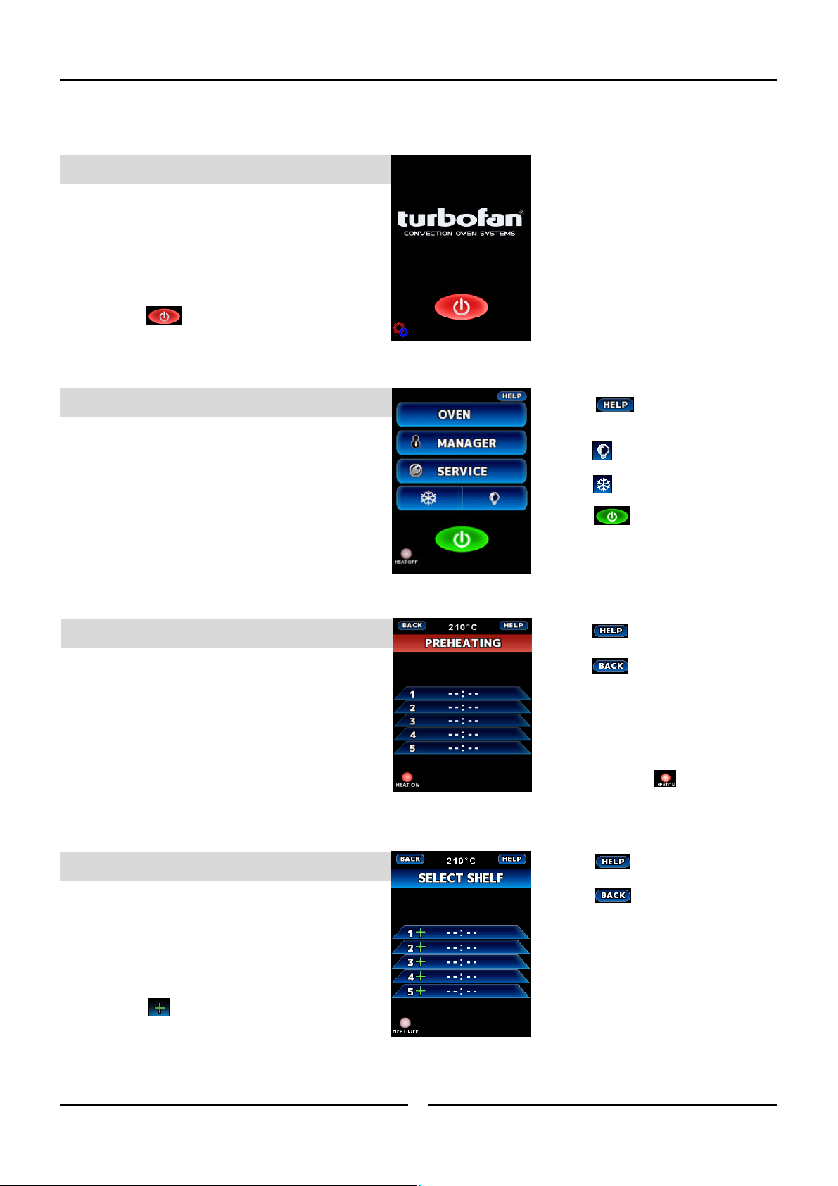
Oven Mode
1. CONTROLOFF
Press key to turn control ON.
2. CONTROLON
Press OVEN to start using oven.
3. PRE‐HEATING
Press to show HELP screen.
(All screens)
Press to turn oven light On/Off.
Press to cool down oven.
Press to turn OFF controller.
Press to show HELP screen.
Press to return to previous screen.
Oven Pre-Heating will occur
automatically.
Shelves cannot be selected until
oven has completed ‘pre-heating’.
4. SELECTSHELF
Always select empty shelves nearest
top of oven first.
Once Pre-Heating has completed.
Press to select shelf.
Up to 5 shelves can be selected.
Heat ‘On’ symbol will illuminate when
oven is heating.
Press to show HELP screen.
Press to return to previous screen.
7
Page 10
Operation - Oven Mode
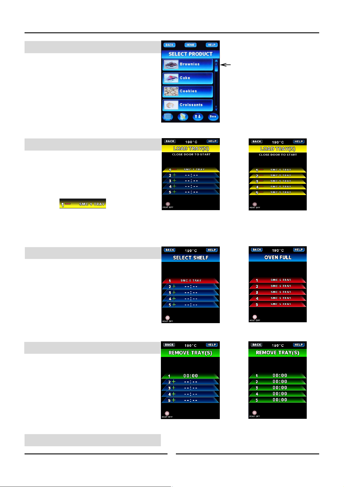
5. SELECTPRODUCT
SELECT product from list.
Alarm will sound when oven is ready to
load.
6. LOADTRAY(S)
LOAD TRAY(S) to selected shelf or shelves.
Always select empty shelves nearest
top of oven first.
Press to cancel a shelf.
Close oven door after loading trays, the
program will start cooking automatically.
7. PROGRAMSTART
When tray shelf is running, it is
coloured RED.
Recipe name and countdown time
alternate in the shelf display.
Press scroll bar to scroll up/down
recipes.
Part Oven Load Full Oven Load
Part Oven Load Full Oven Load
Part Oven Load Full Oven Load
8. DONE‐TIMEUP
Alarm will sound.
OPEN OVEN DOOR.
REMOVE TRAY(s).
Oven alarm and shelf selected will self
cancel when the oven door is closed.
CLOSE OVEN DOOR
9. RETURNTOSTEP4.
8
Page 11

Manager Mode - Recipe Programming
Entering Recipe Programming
1. ENTERMANAGERMODE
Press MANAGER to enter Manager
Mode.
2. ENTERPASSCODE
ENTER passcode (4500).
Press to confirm.
Press to cancel.
3. ENTERRECIPEPROGRAMMING
Press to show HELP screen.
Press to show HELP screen.
Press to exit.
Press to select
4. RECIPEEDITING
Select recipe to edit.
Press for next MANAGER screen.
Press to show HELP screen.
Press to return to previous screen.
Press to select Product Category.
Press to scroll through Recipes.
Press to create a new Recipe.
Press and the Recipe to be deleted,
to remove a recipe.
9
Page 12
Manager Mode - Recipe Programming
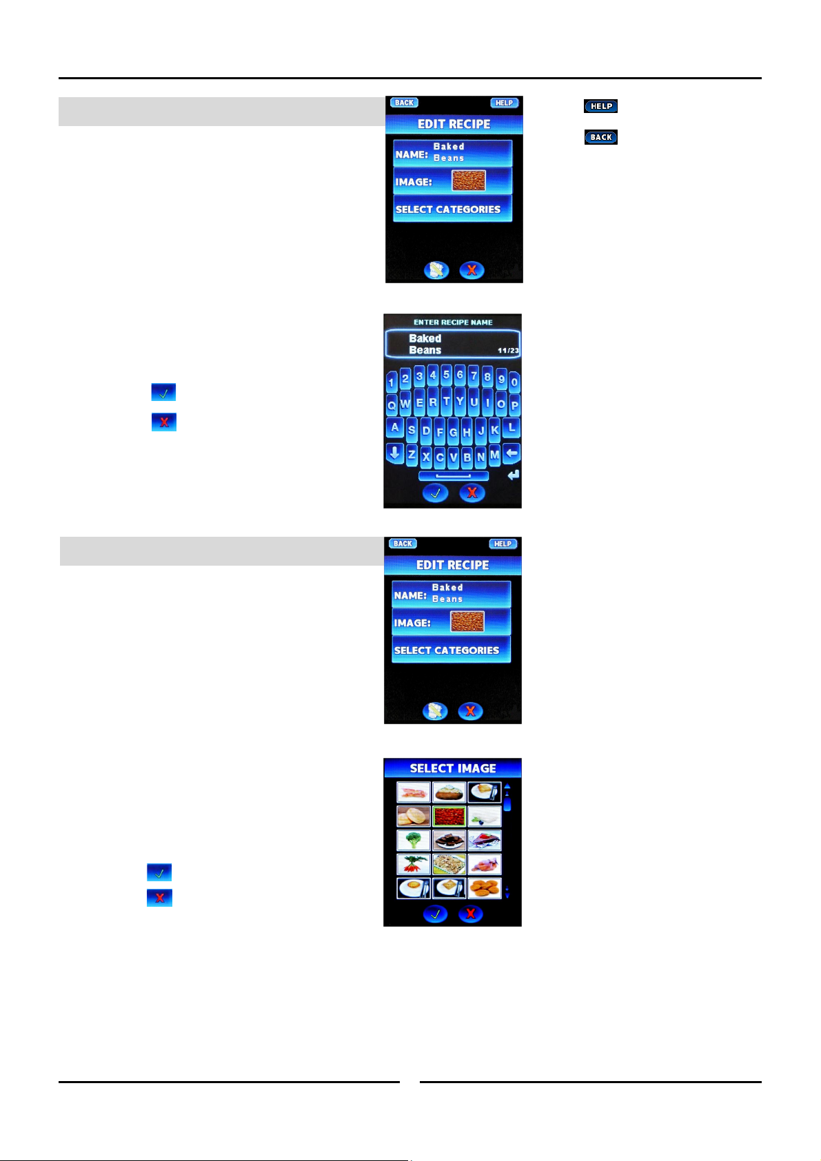
5. RECIPENAMING
In the Edit Recipe screen.
Press recipe name to edit name.
Edit / add recipe name using keypad.
Press to confirm.
Press to cancel.
Display will return to Edit Recipe
screen.
Press to show HELP screen.
Press to return to previous screen.
6. RECIPEIMAGE
Press Image in Edit Recipe screen.
Image gallery will display.
Select image required from Image
gallery.
Press to confirm.
Press to cancel.
Display will return to Edit Recipe
screen.
10
Page 13
Manager Mode - Recipe Programming
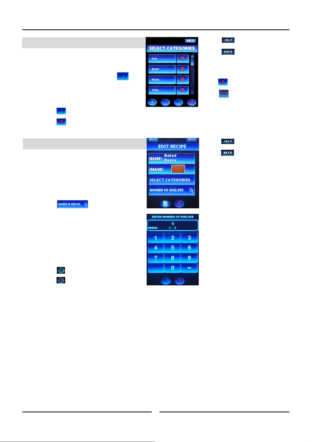
7. RECIPECATEGORY
Press Select Categories in Edit Recipe
screen.
Choose a category and press to
add a recipe to a category.
NOTE: Recipes can be added to more than
one category.
Press to confirm.
Press to cancel.
8. SETNUMBEROFSHELVES
Display will return to Edit Recipe
screen.
Press to select number of
shelves that will be loaded together
when this recipe is selected.
Enter number of shelves on the keypad.
Range 1 to 6.
Press to confirm.
Press to cancel.
Press to show HELP screen.
Press to return to previous screen.
Press to create a new Category.
Press and the Category to be deleted,
to remove a category.
Press to show HELP screen.
Press to return to previous screen.
11
Page 14

Manager Mode - Recipe Programming
9. SETRECIPETIMEANDTEMP
Press to enter recipe settings
Press to set stage temperature
Press to set stage time.
Press to select fan speed.
Press to set time to count Down.
Press to set FLEX time to No.
Select to add a new cooking stage.
Select to delete a cooking stage.
Press to confirm.
Press to cancel.
Press to show HELP screen.
Press to return to previous screen.
12
Page 15

Manager Mode - Settings
Selecting Manager Mode
1. CONTROLON
Select MANAGER.
2. ENTERPASSCODE
ENTER Passcode (4500).
Press to confirm.
Press to cancel.
3. MANAGERSCREEN#1
Press to show HELP screen.
Press to show HELP screen.
Press to exit MANAGER screens.
Press to select . Refer
to previous section, ‘Manager Mode -
Recipe Programming’.
Press to .
Press to .
Press to select .
ONFIGURE PREHEAT SCREEN.
C
Press to set Preheat
Temperature. Enter temperature on
keypad.
Press to confirm.
Press to cancel.
Press for next MANAGER screen.
Press to show HELP screen.
Press to return to previous screen.
13
Page 16

Manager Mode - Settings
4. MANAGERSCREEN#2
Press to adjust.
Press to turn On / Off.
Press to turn On / Off.
Press to enable / disable
key press beep.
5. MANAGERSCREEN#3
Press to enable /
disable MANAGER passcode protection.
Press to adjust screen
brightness.
Press to enter AUTO
DIM SETTINGS.
Press .
Select and follow ‘On-
Screen’ prompts.
Select and follow ‘OnScreen’ prompts.
AUTO DIM SETTINGS SCREEN.
Press Time to adjust
automatic screen dimming time.
Press Brightness to adjust
screen dim percentage.
Press to confirm.
Press to cancel.
Press to show HELP screen.
Press to exit MANAGER screens.
Press for next / previous
MANAGER screen.
Press to show HELP screen.
Press to exit MANAGER screens.
Press for next / previous
MANAGER screens.
Press to show HELP screen.
6. MANAGERSCREEN#4
Press to .
Press to enter oven
temperature Setback (stand-by)
settings.
Press to enter .
Press to view System
Software version.
Press to show HELP screen.
Press to exit MANAGER screens.
Press for next / previous
MANAGER screens.
14
Page 17

Manager Mode - Settings
CHANGE PASSCODE SCREEN.
Press to change
passcode.
Press , numeric key
pad will display. Enter passcode.
Press , numeric key
pad will display. Verify passcode.
Press to confirm.
Press to cancel.
SETBACK OPTIONS SCREEN.
Press to enable /
disable Setback mode.
Press to change
setback time. Enter time on keypad.
Press to change
setback temperature. Enter
temperature on keypad.
AUTOSTART SCREEN.
Press to set Autostart
temperature. Enter temperature on
keypad.
Press to set Autostart
time. Enter time on keypad.
Press to enable /
disable Autostart Mode.
SYSTEM SCREEN.
Screen displays controller system
information.
Press to show HELP screen.
Press to return to previous screen.
Press to show HELP screen.
Press to return to previous screen.
Press to show HELP screen.
Press to return to previous screen.
Press to change from AM to PM.
Press to return to previous screen.
Press to exit MANAGER screens.
15
Page 18

Manager Mode - Settings
7. MANAGERSCREEN#5
Press to enter /
change real time settings.
Press to enter / change
date settings.
Press to enter
Language selection.
Press to change
Temperature Unit settings, °C / °F.
IME ENTRY SCREEN.
T
Enter time.
Press to confirm.
Press to cancel.
ATE ENTRY SCREEN.
D
To change the Day, press ,
numeric key pad will display.
To change the Month, press ,
numeric key pad will display.
To change the Year, press ,
numeric key pad will display.
To change the Day Shown,
press to toggle through.
Press to confirm.
Press to cancel.
SELECT LANGUAGE SCREEN.
Press to select
language required.
Press to confirm.
Press to cancel.
Press to show HELP screen.
Press to exit MANAGER screens.
Press to change from AM to PM.
Press for next / previous
MANAGER screen.
Press to show HELP screen.
Press to return to previous screen.
Press to show HELP screen.
Press to return to previous screen.
16
Page 19

Manager Mode - Settings
8. MANAGERSCREEN#6
E-CALIBRATE TOUCH SCREEN.
R
Press to Re-Calibrate the Touch
Screen.
NOTE; This should only be done if the touch positions
on the screen become difficult to operate.
Warning Reboot Unit? screen will appear.
Press to confirm.
Press to cancel.
Follow the On-Screen prompts.
Press to show HELP screen.
Press to exit MANAGER screens.
Press for previous MANAGER screen.
17
Page 20

Cleaning and Maintenance
Cleaning Guidelines
Caution
Always turn off electrical power at the
mains supply before commencing cleaning.
This oven is not water proof. Do not use
water jet spray to clean interior or exterior
of the appliance.
To achieve the best results, cleaning must be regular and
thorough. If any small faults occur, have them looked at promptly.
Don't wait until they cause a complete breakdown.
NOTE:
Carefully read and follow the safety instructions on
the label of the cleaning product to be used.
DO NOT use harsh abrasive scouring pads or
abrasive detergents as they could damage the
oven.
Ensure that any detergent or cleaning material has
been completely removed after each cleaning.
To keep your oven clean and operating at peak efficiency, follow
the procedures shown below:-
Oven Cleaning
NOTE:
If oven usage is very high, the cleaning procedure
should be carried out more frequently.
Allow the oven interior to cool to approx 50˚C /
120˚F before commencing cleaning.
NOTE: Clean interior of Oven first. This prevents build-up
of soil and fingerprints on exterior of oven whilst
cleaning the interior of each unit.
Activate oven cool-down
function on the controller.
Open oven door.
When the oven temperature
reaches 50°C, the oven will
shut down.
Stainless Steel Surfaces
a. Thoroughly clean the exterior surfaces of the oven
with, a damp cloth moistened with a mild detergent
solution, or a soft bristled brush.
b. Baked on deposits or discoloration may require a
good quality stainless steel cleaner. Always apply
cleaner when the oven is cold and rub in the
direction of the grain.
Side Racks Removal
Right Rack / Fan Baffle
a. Lift up and unhook RH side rack from locating pegs
on RH side of oven. The fan baffle is an integral part
of the RH Side Rack.
R/Hand Front
Locating Peg
b. Tilt top of rack inwards and lift off lower mounting
brackets.
R/Hand Rear
Locating Peg
c. Tilt top of rack inwards and lift off lower mounting
brackets.
Left Rack
a. Lift the LH rack off the front locating peg.
L/Hand Front
Locating Peg
b. Pull rack forward to disengage rear of rack from rear
location peg and remove rack from oven.
L/Hand Rear
Locating Peg
c. Clean the racks with a mild anti bacterial detergent
and hot water, using a soft bristled brush.
d. Dry the racks thoroughly with a dry cloth.
18
Page 21

Cleaning and Maintenance
Side Racks Re-Fitting
Right Rack
a. Align the bottom of the rack with the 2 brackets in
the bottom RH side of the oven.
RH Lower Mounting Brackets
b. Tilt the rack upwards and hook the top of the rack
onto the locating pegs in the top of the oven.
R/Hand Rear
Locating Peg
Oven Lamp
a. Remove the LH side rack as shown previously.
b. Wash the glass lens with a soft sponge using warm
water and a detergent solution. Rinse with clean,
warm water.
R/Hand Front
Locating Peg
Left Rack
a. Locate the top rear of the rack onto the locating peg
at the top rear LH side of the oven.
L/Hand Rear
Locating Peg
b. Locate the top front of the rack over the locating peg
at the top front LH side of the oven.
c. Dry the glass lens thoroughly with a dry cloth.
d. Refit LH side rack as shown previously.
19
Page 22
Cleaning and Maintenance
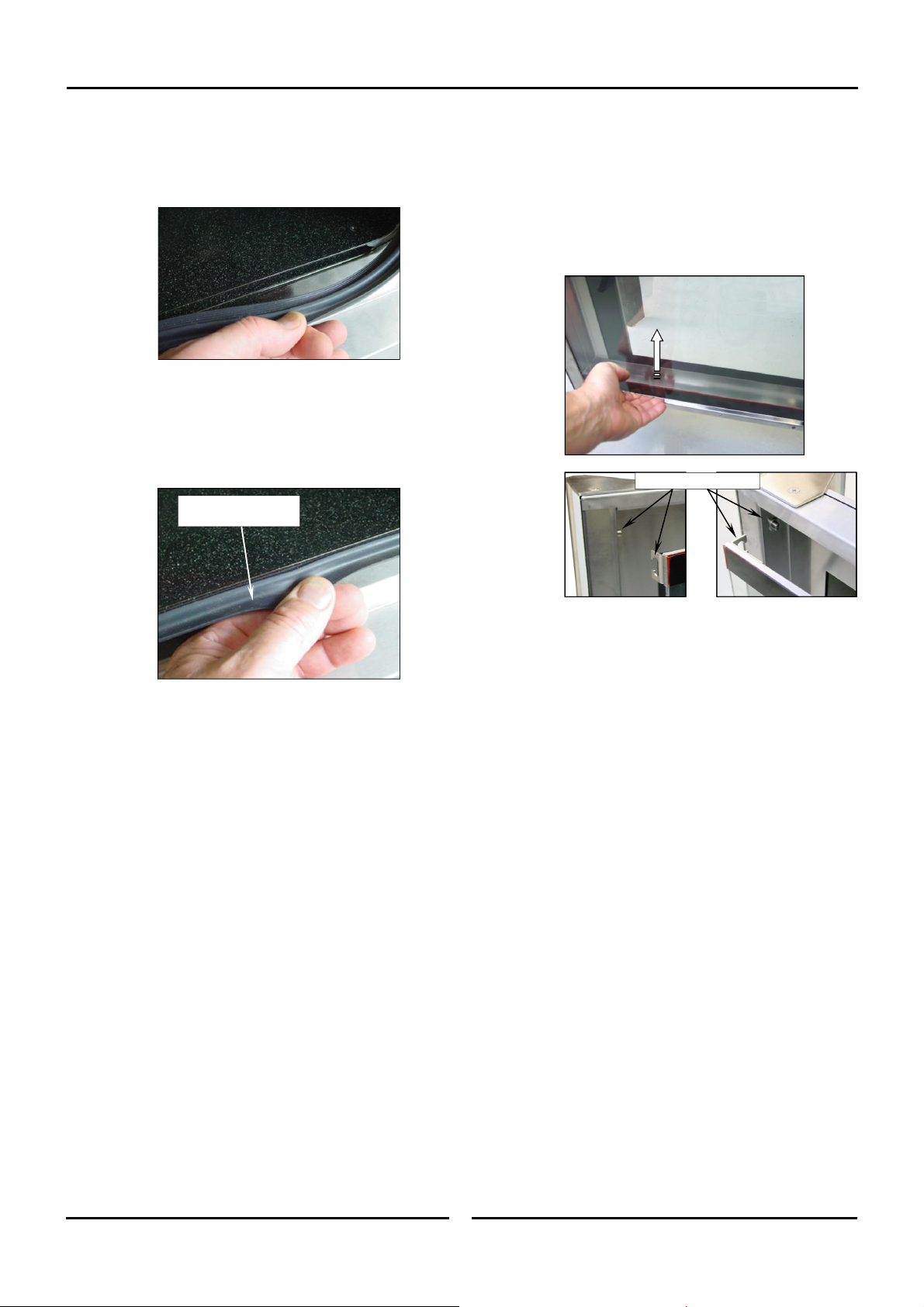
Door Seal
a. To remove the door seal, pull the 1 piece seal
forward until it pulls out of the location groove
around the oven. Note the way the seal is fitted
to the oven, with the lip facing inwards.
b. Check the door seal for wear and damage and
replace as required.
c. Wash the door seal in a sink, taking care not to cut
or damage the seal.
d. Dry the door seal thoroughly.
e. Refit the door seal with lip facing into centre of the
oven.
Push Seal carefully into
locating channel
Door Glass Cleaning
Ensure that the oven door is cool before
cleaning the oven door glass.
a. Open the oven door.
b. Lift up the bottom of the inner glass at the centre of
the door to unlock from the inner glass retaining
catches and swing the glass inwards towards the
oven.
Top Locking Catches
f. Press the door seal into the locating groove in the
front face of the oven until the seal is properly
located all around the oven.
Oven Interior
Allow the oven interior to cool to approx 50˚C /
120˚F before commencing cleaning.
a. Remove the oven racks as shown previously.
b. Clean any build up of grease from the oven interior,
using a soft bristled brush with a solution of hot
water and a mild anti bacterial detergent.
c. Dry the oven thoroughly with a soft dry cloth.
d. Clean the oven regularly with a good quality oven
cleaner.
c. Clean both sides of the inner glass and the inner side
of the outer door glass with a conventional glass
cleaner.
d. Dry the oven door thoroughly with a soft dry cloth.
e. Swing the inner glass back towards the outer door.
f. Whilst holding the outer door, lift the inner glass
back onto the locking catches until the inner glass is
securely held.
Periodic Maintenance
NOTE: All maintenance operations should only be carried
out by a qualified service person.
Controls and mechanical parts should be checked and adjusted
periodically by a qualified service person. It is recommended that
the appliance is serviced every 6 months.
20
Page 23

Electrical Schematics
Electrical Schematic E33T C-Store - (High Speed Option - 2 Speed Fan Motor).
21
Page 24

Electrical Schematics
Electrical Schematic E33T C-Store - (Standard 2 Speed fan Motor).
22
Page 25
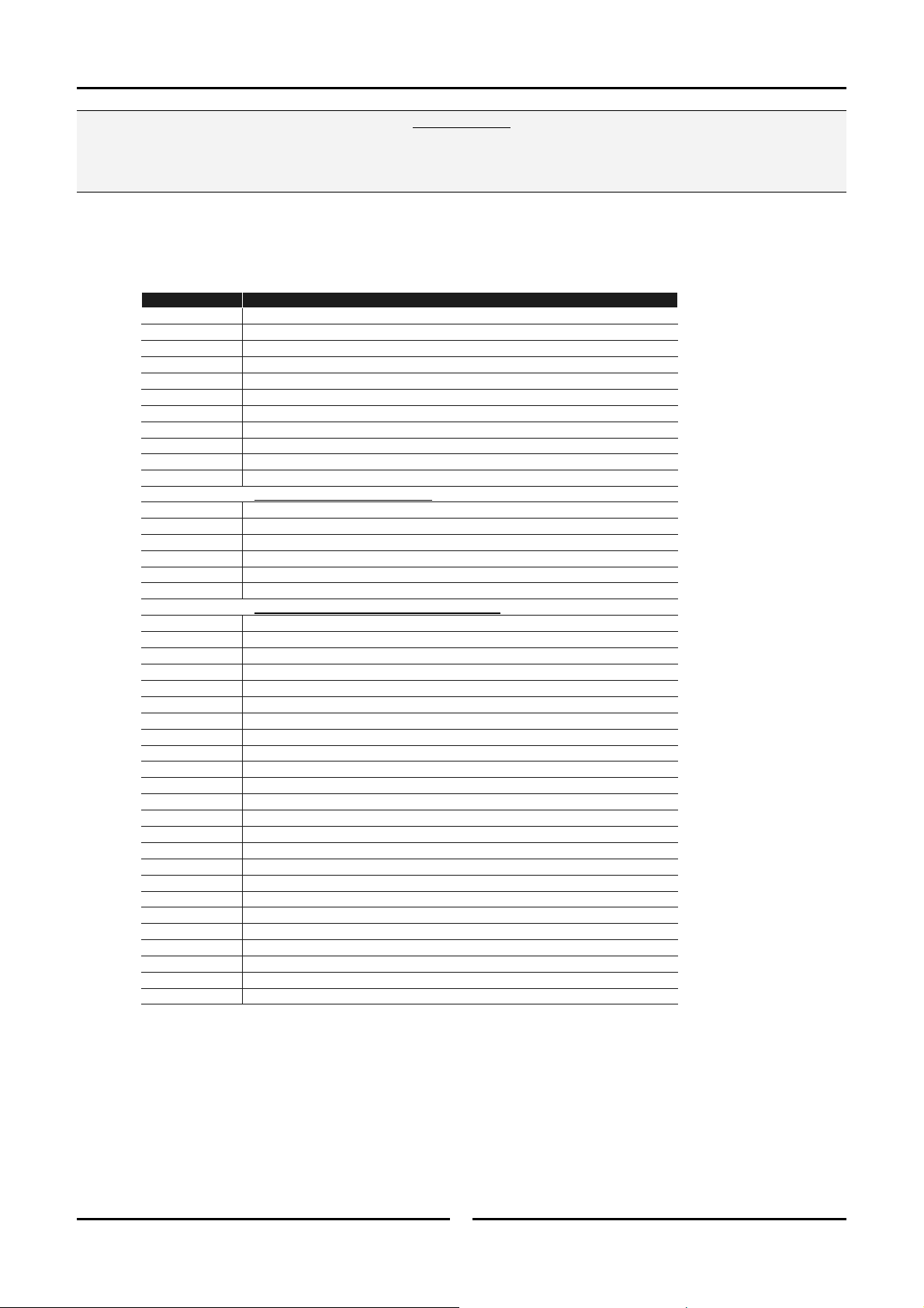
Replacement Parts List
Only genuine authorized replacement parts should be used for the servicing and repair of this oven. The instructions
supplied with the parts should be followed when replacing components.
For further information and servicing instructions, contact your nearest authorized service provider or Turbofan Dealer.
When ordering replacement parts, please quote the part number and the description as listed below. If the part required is not listed
below, request the part by description and quote model number and serial number which is shown on the Technical Data Plate.
Item Description
235657 Control Panel Laminated E33T.
236258 Touch Screen Controller Kit.
235700 USB Cable Panel Mount Type A, 0.3m.
235701 USB Protective Cap, Type A.
235848 Reed Switch
235698 Transformer 208 / 240V x 24V, 40VA.
236713 Cooling Fan, 24VDC.
236202 Oven Temperature Probe - T Series.
234821 Overtemp Thermostat 355°C / 670°F.
308155 Contactor (Heating), 24VDC, 20A (Eaton).
Standard 2 Speed Fan Motor
235625 Fan Motor 208-240V, 50/60Hz, 4/8 Pole.
234138 Fan 220mm (50/60Hz).
236054 Motor Capacitor 8uF (50Hz).
236053 Motor Capacitor 6.3uF (60Hz).
236217 Contactor Mini 3P+1NC, 24VDC.
High Speed Option - 2 Speed Fan Motor
237335 Fan Motor 208-240V, 50/60Hz, 2/4 Pole.
234138 Fan 220mm (50Hz).
234625 Fan 200mm (60Hz).
234252 Motor Capacitor 10uF.
234875 Motor Capacitor 3uF.
235610 Motor Shaft Seal.
235420 Fan Puller / Tightener.
235696 Relay Single Pole, Double Throw, 20A, 24VDC.
235695 Relay Single Pole, Single Throw, 20A, 24VDC.
236109K Oven Element, 5800W, 230 - 240V.
236110K Oven Element, 5800W, 208 - 220V.
236264 Element Gasket.
021353 Support Frame
021352 Oven Glass Lens.
236214 Lampholder (231814 25W lamp included).
231814 Lamp Bulb G9 25W, Halogen, 230V.
021354 Oven Lamp Gasket.
234803 Fuse 10A, 250V.
234802 Fuse Holder.
020851 Water Solenoid.
021057 Spray Nozzle Assembly.
Important:
23
Page 26

Replacement Parts List
Replacement Parts List (Cont.d)
Item Description
235615 Oven Seal - E33T.
236203 Door Outer Glass Assembly E33.
237167
234752 Hinge Pivot Kit (Includes Door Hinge Pivot Pin, Pivot Bush, Washer M8 Nord-Lock).
235652 Door Inner Glass Assembly
234779 Inner Glass Retaining Clip
234767 Door Pivot Spacer
235859 Door Handle Assembly E33T
231804 Single Step Locking Dog
236014 Door Locking Dog Escutcheon
235015 Door Strike Escutcheon Washer
235849 Door Actuator Magnet
232379 Leg Adjustable 73-80mm
232380 O-Ring
237020 Side Rack LH, 5 Tray - 1/1GN.
237015 Side Rack RH, 5 Tray - 1/1GN.
238676 Side Rack LH, 4 Tray - 1/1GN.
238678 Side Rack RH, 4 Tray - 1/1GN.
238727 Side Rack LH, 4 Tray 238728 Side Rack RH, 4 Tray -
Door Hinge Kit ( includes Door Hinge Set Bottom, Door Hinge Set Top, Door Hinge Pivot Pin,
Pivot Bush, Washer M8 Nord-Lock, Gaskets and Screws).
1
/2 US Pan (USA / Canada Only).
1
/2 US Pan (USA / Canada Only).
24
Page 27

 Loading...