


E32MS CONVECTION
OVEN
SERVICE MANUAL
Revision 6/F3587 |
-1- |
© Moffat Ltd, January 2009 |
|
|


 WARNING: ALL INSTALLATION AND SERVICE REPAIR WORK MUST BE CARRIED

 OUT BY QUALIFIED PERSONS ONLY.
Revision 6/F3587 |
-2- |
© Moffat Ltd, January 2009 |
|
|

CONTENTS
This manual is designed to take a more in depth look at the E32M and E32MS convection ovens for the purpose of making the units more understandable to service people.
There are settings explained in this manual that should never require to be adjusted, but for completeness and those special cases where these settings are required to change, this manual gives a full explanation as to how, and what effects will result.
SECTION |
|
PAGE NO. |
|
1. |
SPECIFICATIONS......................................................................................................... |
5 |
|
2. |
INSTALLATION............................................................................................................. |
7 |
|
3. |
OPERATION .................................................................................................................. |
10 |
|
|
3.1 |
Description of Controls |
|
|
3.2 |
Explanation of Control System |
|
4. |
MAINTENANCE............................................................................................................. |
13 |
|
4.1Cleaning
4.2Routine Procedures
5. |
TROUBLE SHOOTING GUIDE ..................................................................................... |
15 |
|
6. |
SERVICE PROCEDURES ............................................................................................. |
19 |
|
|
6.1 |
Fault Diagnosis |
|
|
6.2 |
Access |
|
|
6.3 |
Replacement |
|
|
6.4 |
Adjustment / Calibration |
|
7. |
ELECTRICAL SCHEMATICS........................................................................................ |
36 |
|
8. |
ELECTRICAL WIRING DIAGRAMS ............................................................................. |
37 |
|
9. |
SPARE PARTS.............................................................................................................. |
38 |
|
10. |
ACCESSORIES / OPTIONS.......................................................................................... |
39 |
|
 IMPORTANT: MAKING ALTERATIONS MAY VOID WARRANTIES AND APPROVALS.
Revision 6/F3587 |
-3- |
© Moffat Ltd, January 2009 |
|
|

11. PARTS DIAGRAM......................................................................................................... |
40 |
11.1Main Assembly
11.2Control Panel Assembly
11.3Gear Plate Assembly
11.4Door Assembly
12. SERVICE CONTACTS .................................................................................................. |
47 |
APPENDIX A. STACKING BASE STAND............................................................................. |
49 |
APPENDIX B. DOUBLE STACKING KIT.............................................................................. |
50 |
Revision 6/F3587 |
-4- |
© Moffat Ltd, January 2009 |
|
|

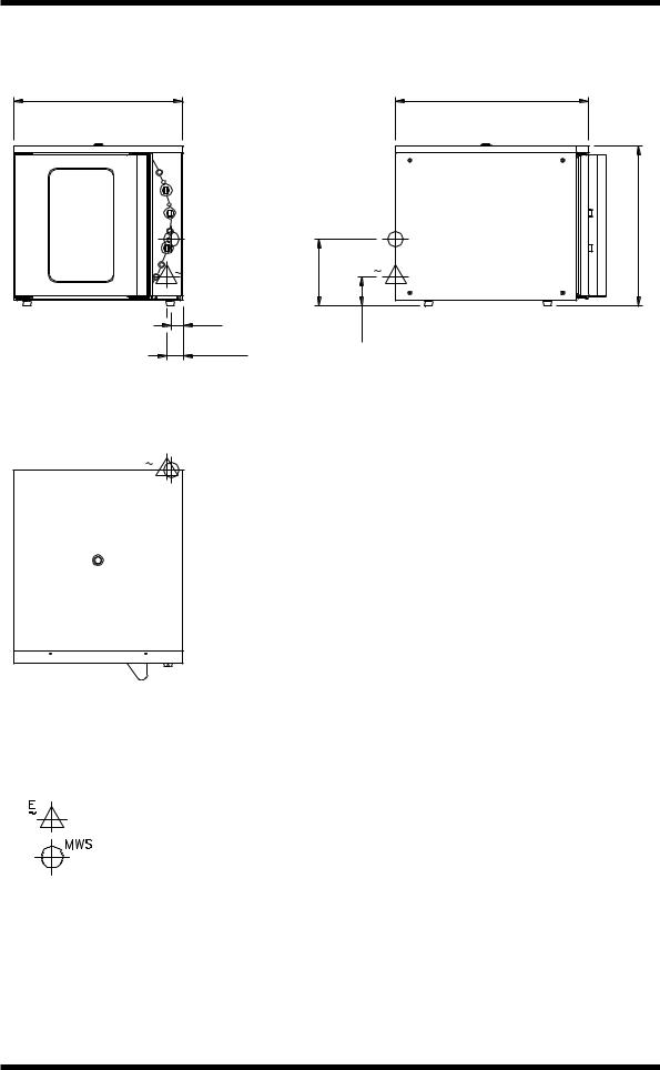
1. SPECIFICATIONS
MODEL: E32M
710 |
810 |
(28") |
(32") |
|
|
MWS |
|
|
|
MWS |
|
1 |
E |
280 |
(11") |
1 E |
|
|
|
|
|
|
|
|
|
|
50 |
|
120 |
(4¾") |
|
FRONT |
|
(2") |
70 |
SIDE |
||
|
|
|
||||
|
|
|
|
(2¾")
1 E MWS
PLAN
LEGEND
-Electrical connection entry point
-Water entry - ¾” BSP hose connection
Dimensions shown in millimetres.
Dimensions in inches shown in brackets.
670 |
(26½") |
Revision 6/F3587 |
-5- |
© Moffat Ltd, January 2009 |
|
|
MODEL: E32MS
710 |
810 |
(28") |
(32") |
MWS MWS
|
1 E |
280 |
(11") |
1 E |
|
|
|
||
|
|
50 |
120 |
(4¾") |
|
|
(2") |
||
|
|
|
|
|
FRONT |
|
70 |
|
SIDE |
|
|
(2¾") |
|
|
1 E MWS
PLAN
LEGEND
-Electrical connection entry point
-Water entry - ¾” BSP hose connection
Dimensions shown in millimetres.
Dimensions in inches shown in brackets.
670 |
(26½") |
Revision 6/F3587 |
-6- |
© Moffat Ltd, January 2009 |
|
|

LOCATION
To ensure correct ventilation for the motor and controls the following minimum installation clearances are to be adhered to:
Rear |
75mm / 3“ |
Left-hand side |
75mm / 3” |
Right-hand side* |
75mm / 3” |
Top |
200mm / 8” |
*Fixed installations require at least 500mm (20”) clearance at the right hand side for service accessibility.
OVEN INTERNAL DIMENSIONS
Width |
468 mm / 18.5” |
Height |
533 mm / 21” |
Depth |
711 mm / 28” |
Oven Volume |
0.18 m³ / 6.3 ft³ |
OVEN RACK SIZE |
|
Width: |
460 mm / 18” |
Depth: |
660 mm / 26” |
No of rack positions: |
4 |
Rack position spacing: |
125 mm / 5” |
ELECTRICAL SUPPLY SPECIFICATION OPTIONS
208 V AC 60 Hz, 28.8 A , 6.0 kW@ 208 V 220-240 V AC 60 Hz, 27.8 A, 6.7 kW @ 240 V 208-220 V AC 50 Hz, 28.8 A, 6.0 kW @ 208 V 230-240 V AC 50 Hz, 27.8 A, 6.7 kW @ 240 V
ELECTRICAL CONNECTION WIRE CONDUCTOR SIZES
Minimum: 4mm² / 16 AWG
WATER SUPPLY CONNECTION
Max Pressure |
550 kPa / 5.5 bar / 80 psi |
Min Pressure |
100 kPa / 1.0 bar / 15 psi |
Revision 6/F3587 |
-7- |
© Moffat Ltd, January 2009 |
|
|
2. INSTALLATION


 WARNING: THIS APPLIANCE MUST BE GROUNDED.

 WARNING: ALL INSTALLATION AND SERVICE REPAIR WORK MUST BE CARRIED

 OUT BY QUALIFIED PERSONS ONLY.
Before Connection to Power Supply
•Remove all packing.
•Check equipment and parts for damage. Report any damage immediately to the carrier and distributor.
•Remove protective plastic coating from the side panels.
•Check that the following parts have been supplied with your oven:
4 x Foot assembly
4 x Oven racks
1 x Water inlet elbow (c/w washer)
•Report any deficiencies to the distributor who supplied the oven.
•Fit the feet to the oven.
•Check that the available power supply is correct to that shown on the rating plate located on the right -hand side panel.
208-220 V AC, 50 Hz, 28.8 A, 6.0 kW 208 V AC, 60 Hz, 28.8 A, 6.0 kW 230-240 V AC, 50 Hz, 27.8 A, 6.7 kW 220-240 V AC, 60 Hz, 27.8 A, 6.7 kW
Location
•To ensure correct ventilation for the motor and controls the following minimum installation clearances are to be adhered to:
Rear |
75mm / 3” |
Left-hand side |
75mm / 3” |
Right-hand side* |
75mm / 3” |
Top |
200mm / 8” |
*Fixed installations require at least 500mm (20”) clearance at the right hand side for service accessibility.
•Position the oven in its working position.
IMPORTANT: THE OVEN VENT LOCATED ON THE CABINET TOP MUST NEVER BE OBSTRUCTED.
•Use a spirit level to ensure oven is level from side to side and front to back. (If this is not carried out, uneven cooking could occur). The feet/legs used with bench/
floor mounting or provided with stands are adjustable and will require adjusting in levelling the unit.
•The unit should be positioned such that the operating panel and oven shelves are easily reachable for loading and unloading.
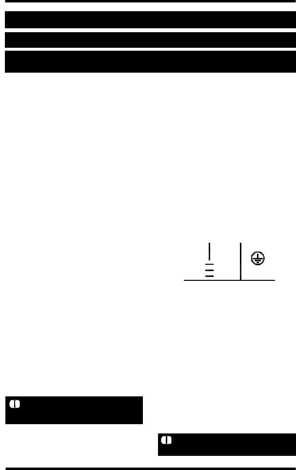
Electrical Connection
•Remove right hand side panel to allow access to the terminal block and strain relief cable clamp.
•The cable can be fitted through the small grommet and held by the cable clamp.
•Connect cable to the terminals as marked.
•Refit cover panel.
L1 |
L2 |
Ground |
|
Phase |
Neutral |
|
|
RED |
BLACK |
GREEN |
|
BROWN |
BLUE |
||
GREEN/YELLOW |
|||
BLACK |
WHITE |
||
|
|
WARNING: THIS APPLIANCE MUST |
|
BE GROUNDED / EARTHED |
Figure |
2.1 |
Water Connection
•A cold water supply should be fitted to the water inlet (¾” BSP hose connection) which is located on the rear of the right hand side of the unit.
•Alternately, a connection elbow and sealing washer is supplied with this unit for direct connection of a ½” ID hose, and is recommended for easy installation and service.
•Connect water supply - Max inlet pressure 80psi / 550kPa.
•Turn on water supply to check for leaks.
IMPORTANT: MAXIMUM INLET WATER PRESSURE IS 550 kPa / 80 psi.
Revision 6/F3587 |
-8- |
© Moffat Ltd, January 2009 |
|
|
Before Use
•Operate the oven for about 1 hour at 200°C (400°F) to remove any fumes or odours which may be present.
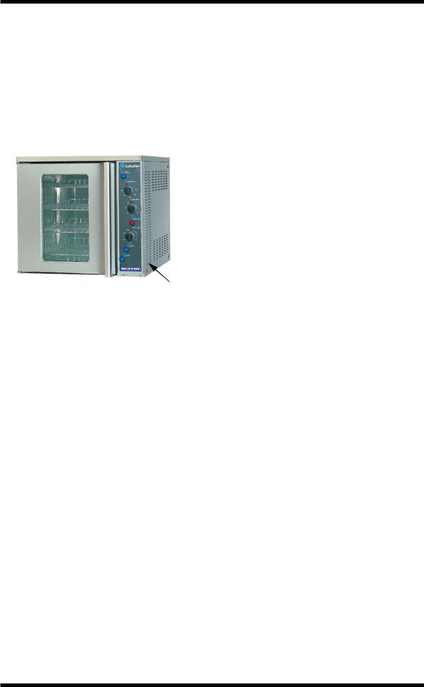
Rating Plate Location
The rating plate for the E32M and E32MS convection ovens is located at the bottom front corner of the RH side panel.
|
Rating |
Figure 2.3 |
Plate |
|
|
|
Revision 6/F3587 |
-9- |
© Moffat Ltd, January 2009 |
|
|

3. OPERATION
NOTE: A full user’s operation manual is supplied with the product and can be used for further referencing of installation, operation and service.
3.1 DESCRIPTION OF CONTROLS
1.Power
Depress to switch power on or off (switch illuminates when power is on).
2.Thermostat
Temperature range 50 - 320°C (120 - 600°F). Indicator illuminates when elements are cycling ON to maintain set temperature.
3.Bake Timer
1 Hour bake timer.
(Indicator illuminates when “time up” (0) reached, and buzzer sounds).
4.Roast ‘n’ Hold
Depress switch to activate ’Roast ’n’ Hold’ function. (Switch illuminates when ON).
5.Roast Timer
3 Hour roast timer.
(Indicator illuminates when “time up” (0) reached, and product held at 75°C (167°F).
6.Steam Switch
Push switch to activate water injection. (Water injects into oven while the button is depressed).
7.Light Switch
Push switch to activate lights.
1
2
3
4
5
6
7
Revision 6/F3587 |
-10- |
© Moffat Ltd, January 2009 |
|
|
3.2EXPLANATION OF CONTROL SYSTEM
The E32M and E32MS Turbofan convection ovens feature multi-function operator controls for which a correct understanding of their operation is required before carrying out any service or fault repair work. The control device functions are explained as follows:
A power switch on the control panel isolates power to the controls of the oven. With the power switch Off all functions of the oven are inoperable.
With the power switch On (illuminated) power is directly supplied to the 60 minute bake timer, steam (water injection) switch, door microswitch, light switch, and the temperature control circuit. The oven circulation fan will operate whenever the power switch is on. The control panel light switch will turn the oven lights on when the door is closed. The oven lights will come on automatically when the door is open, as this is controlled by the door microswitch. The oven fan and heating elements are also controlled by the door microswitch, and will therefore only operate when the door is closed.
The 60 minute timer is a mechanical timer and can therefore be operated with the oven’s power switch On or Off. However, only with the oven’s power switch On will the switch contacts of the 60 minute timer turn on the time-up buzzer and illuminate the time-up indicator on the control panel. The buzzer and time-up indicator provide indication that the time setting has run down to zero and at this point will remain On continuously until the 60 minute timer has been manually set back to the Off (vertical) position. The 60 minute timer does not control any other part of the oven’s operating system as this timer is independent of the temperature control and heating system.
The steam (water injection) switch on the control panel can be operated whenever the power switch is On. The switch is momentary like the light switch and when depressed, will operate the electric solenoid valve at the rear of the oven and inject water across the elements and fan from the flat spray (vertical) nozzle positioned at the rear of the oven elements. Releasing the steam button will close the solenoid valve. This feature is used to instantaneously add steam into the oven.
The temperature control of this oven is with a capillary type thermostat which can be set to a required cooking temperature.
The control panel indicator light above the thermostat knob cycles On and Off with the thermostat to indicate when the elements are on and the oven is heating.
The E32M and E32MS Turbofan convection ovens have 6.5 kW of electric heating elements, comprising of a 3 kW inner coil, and a 3.5 kW outer coil, both of which make up the element assembly around the oven fan. The elements are switched on and off by the main oven thermostat or hold thermostat via a four-pole 25 Amp contactor located inside the control housing. Only two poles of the contactor are used, one for each element coil. Power to the oven thermostat is supplied from the door microswitch, and will therefore only switch the elements on if the oven door is closed.
The circulation fan on the E32M and E32MS ovens reverses direction every 90 seconds for a 50Hz supply (every 75 seconds for 60Hz). Prior to a change of direction the fan motor is switched off for 10 seconds (8½ seconds for 60Hz) to allow the motor/fan to slow down. Cycling of the fan motor is controlled by a continuous cam timer with electric motor. The timer has two cams and switches which supply power alternately to one of two motor supply wires, causing the motor to alternate direction. During the fan motor slow down periods, both cam switches are open and power is not supplied to either of the motor supply wires. When the oven door is opened or the power is switched off the cams will stop. When the oven door is closed or the power switched back on the cam timer will resume its cycle from the point where it stopped.
The fan motor is a split phase continuous capacitor motor with the capacitor externally connected across the motor supply leads. The motor also incorporates an internal thermal trip switch for overheat protection which is auto resetting.
The E32M and E32MS Turbofan convection ovens feature a Roast-and-Hold system which can be used to automatically set the oven to a fixed holding temperature at the end of a timed cooking period. When the Roast-and- Hold switch is turned On the switch will illuminate and switch on a hold relay found
Revision 6/F3587 |
-11- |
© Moffat Ltd, January 2009 |
|
|

inside the control panel. When the relay is switched ON a normally closed switch pole on the relay is opened and the normal power supply to the oven thermostat is isolated. A second normally open switch pole is closed and this provides power to the 3 hour roast timer.
If the roast timer is in the Hold (vertical) position the timer switch contacts will be in their normally closed position and supply power directly to the Hold thermostat located behind the control panel. The Hold thermostat is factory set to 75°C (167°F) and will supply power to the heating elements through the heating contactor as required to maintain its preset temperature.
The thermostat heating light will also cycle On/Off as the Hold thermostat maintains temperature.
In the Roast-and Hold mode the 3 hour timer can be set to a selected roasting time. During this time period the normally open switch contacts of the timer are closed. The timer has two change over switches and in this position one is used to supply power to its timing motor and the other is used to switch power directly to the main oven thermostat. During the 3 hour timer run-down period the oven temperature will be controlled by the main oven thermostat to the set temperature and operate as previously described.
When the 3 hour timer has run down and reached the Hold position the two switch contacts change over to their normally closed position which isolates power from the timer motor and the oven thermostat. It also switches power back to the oven hold thermostat. At this point the temperature control is now maintained by the hold thermostat as previously described. To cancel the hold circuit the Roast-and-Hold switch is turned Off. This turns off the contactor which removes power from the 3 hour timer and closes the contactor pole on the contactor that feeds the main oven thermostat. The Hold indicator light above the 3 Hour timer will illuminate whenever the oven is operating in hold mode (Roast ‘n Hold selected, and 3 Hour timer at zero position).
The factory preset hold thermostat can be adjusted as required to change the holding temperature if necessary. Refer Service section for this procedure.
The following Troubleshooting Guide should be used to identify any incorrect oven operation. On correct identification of the operating fault the Troubleshooting Guide will make reference to the corrective action required, or refer to the Fault Diagnosis section and / or Service section to assist in correction of the fault.
Revision 6/F3587 |
-12- |
© Moffat Ltd, January 2009 |
|
|

4. MAINTENANCE


 WARNING: ALL INSTALLATION AND SERVICE REPAIR WORK MUST BE CARRIED
 OUT BY QUALIFIED PERSONS ONLY.
4.1 CLEANING

 WARNING: ALWAYS TURN THE

 POWER SUPPLY OFF BEFORE CLEANING.
IMPORTANT: THIS UNIT IS NOT WATER PROOF.
DO NOT USE A WATER JET SPRAY TO CLEAN INTERIOR OR EXTERIOR OF THIS UNIT.
EXTERIOR
Clean with a good quality stainless steel cleaning compound. Harsh abrasive cleaners may damage the surface.
INTERIOR
Ensure that the oven chamber is cool. Do not use wire brushes, steel wool or other abrasive materials. Clean the oven regularly with a good quality oven cleaner. Take care not to damage the fan or the tube at the right side of the oven which controls the thermostat.
OVEN RACKS
To remove, slide out to the stop position, raise the front edge up, and lift out.
SIDE RACKS
To remove, lift front top to disengage and slide rack forward. To replace, slide top rear slot in rack onto rear stud, then engage front keyhole on front stud.
LAMP GLASS
To remove glasses, unscrew anti-clockwise. To replace, screw in clockwise.
IMPORTANT: DO NOT OVER TIGHTEN LAMP GLASS.
OVEN SEALS
To remove, hold at their centre point and pull forward until they unclip. Remove side seals first, then top and bottom. The seals may be washed in the sink, but take care not to cut or damage them. To replace, ensure that the lip is facing the oven opening. Fit the top and bottom seals first, then the side seals.
OVEN DOOR GLASS
Clean with conventional glass cleaners.
Revision 6/F3587 |
-13- |
© Moffat Ltd, January 2009 |
|
|

4.2 ROUTINE PROCEDURES
|
PROCEDURE |
INTERVAL |
DOOR SEALS |
Check for deterioration. |
12 months |
DOOR PIVOT BUSHES |
Check for wear. |
12 months |
DOOR CATCHES |
Ensure that catches are adjusted such that the door |
12 months |
|
closes properly. |
|
ELEMENT |
Check that element resistance is correct to it’s rating |
12 months |
|
(refer 6.3.15). |
|
WATER NOZZLE |
Check for liming in water nozzle. |
12 months |
|
|
|
Revision 6/F3587 |
-14- |
© Moffat Ltd, January 2009 |
|
|

5. TROUBLE SHOOTING

 WARNING: ALL INSTALLATION AND SERVICE REPAIR WORK MUST BE CARRIED

 OUT BY QUALIFIED PERSONS ONLY.
FAULT |
POSSIBLE CAUSE |
REMEDY |
|
|
|
THE OVEN DOES NOT |
The mains isolating switch on |
Turn on. |
OPERATE / START |
the wall, circuit breaker or fuses |
|
|
are “off” at the power board. |
|
|
The power switch on the oven is |
Depress switch. Switch will |
|
off. |
illuminate. |
|
Incorrect electrical supply. |
Ensure electrical supply correct. |
|
(Refer fault diagnosis 6.1.1) |
|
|
Power switch on unit faulty. |
Replace. |
|
(Refer fault diagnosis 6.1.1) |
(Refer service section 6.3.4) |
FAN DOESN’T OPERATE |
Door not closed. |
Close door. |
|
Fan obstructed. |
Clear obstruction. |
|
Door microswitch is out of |
Adjust. |
|
adjustment. |
(Refer service section 6.4.2) |
|
(Refer fault diagnosis 6.1.2) |
|
|
Door microswitch faulty. |
Replace. |
|
(Refer fault diagnosis 6.1.2) |
(Refer service section 6.3.2) |
|
Motor timer faulty. |
Replace. |
|
(Refer fault diagnosis 6.1.2) |
(Refer service section 6.3.18) |
|
Motor capacitor faulty. |
Replace. |
|
(Refer fault diagnosis 6.1.2) |
(Refer service section 6.3.19) |
|
Fan motor faulty. |
Replace. |
|
|
(Refer service section 6.3.17) |
|
Wiring. |
Check and tighten any loose |
|
|
wiring. |
FAN ONLY OPERATES IN |
Motor timer faulty. |
Replace. |
ONE DIRECTION |
(Refer fault diagnosis 6.1.2) |
(Refer service section 6.3.13) |
OVEN LIGHT NOT |
Blown bulb. |
Replace. |
ILLUMINATING - DOOR OPEN |
|
(Refer service section 6.3.1) |
(AUTOMATICALLY ON) |
No power to light. |
Correct fault. |
|
||
|
(Refer fault diagnosis 6.1.3) |
|
OVEN LIGHT NOT |
Blown bulb. |
Replace. |
ILLUMINATING - DOOR |
|
(Refer service section 6.3.1) |
CLOSED |
|
|
(MANUALLY SWITCHED ON) |
Light switch faulty. |
Replace. |
|
(Refer fault diagnosis 6.1.4) |
(Refer service section 6.3.4) |
Revision 6/F3587 |
-15- |
© Moffat Ltd, January 2009 |
|
|

FAULT |
POSSIBLE CAUSE |
REMEDY |
|
|
|
NO WATER INJECTION / |
Water not turned on. |
Turn water on at water supply. |
STEAM |
Oven water nozzle blocked. |
Remove, clean or replace. |
|
||
|
|
(Refer service section 6.3.14) |
|
Fault with water valve. |
Service or replace as required. |
|
(Refer fault diagnosis 6.1.5) |
(Refer service section 6.3.12, |
|
|
6.3.13) |
|
Steam switch faulty. |
Replace. |
|
|
(Refer service section 6.3.4) |
CONTINUOUS WATER OUT |
With oven on only—Electrical |
Correct electrical fault. |
OF OVEN WATER NOZZLE |
fault. |
|
|
(Refer fault diagnosis 6.1.6) |
|
|
With oven on or off - water |
Service or replace as required. |
|
valve faulty or requires |
(Refer service section 6.3.12, |
|
cleaning. |
6.3.13) |
|
|
|
60 MINUTE TIMER WILL NOT |
Timer faulty. |
Replace. |
TIME DOWN |
|
(Refer service section 6.3.7) |
60 MINUTE TIMER |
Timer not set correctly. |
For timer settings below 20 |
INACCURATE BELOW 20 |
|
minutes, always rotate past 20 |
MINUTES |
|
minutes, then back to desired |
|
|
time. |
|
Zero (time up) position not set |
(Refer service section 6.4.6) |
|
correctly. |
|
60 MINUTE TIMER NO TIME |
Buzzer faulty. |
Replace. |
UP BUZZER |
(Refer fault diagnosis 6.1.7) |
(Refer service section 6.3.5) |
|
Timer not switching on buzzer. |
Replace. |
|
(Refer fault diagnosis 6.1.7) |
(Refer service section 6.3.7) |
60 MINUTE TIMER NO TIME |
Indicator faulty. |
Replace. |
UP INDICATOR |
(Refer fault diagnosis 6.1.8) |
(Refer service section 6.3.3) |
NO HEAT |
No power to thermostat. |
Identify fault and correct. |
|
(Refer fault diagnosis 6.1.9) |
|
|
Thermostat faulty. |
Replace. |
|
(Refer fault diagnosis 6.1.9) |
(Refer service section 6.3.9) |
|
Heating contactor faulty. |
Replace. |
|
(Refer fault diagnosis 6.1.9) |
(Refer service section 6.3.11) |
|
Element faulty (blown). |
Replace. |
|
(Refer fault diagnosis 6.1.9) |
(Refer service section 6.3.15) |
NO TEMPERATURE |
Heating contactor faulty. |
Replace. |
CONTROL (TEMPERATURE |
(Refer fault diagnosis 6.1.9) |
(Refer service section 6.3.11) |
OVERRUN) |
Thermostat faulty. |
Replace. |
|
||
|
(Refer fault diagnosis 6.1.10) |
(Refer service section 6.3.9) |
|
|
|
Revision 6/F3587 |
-16- |
© Moffat Ltd, January 2009 |
|
|
 Loading...