

Moffat E32D5-P12M Installation Manual
30D
E32D5
(Digital Operation)
SERIES
Installation and Operation Manual
234782-1

MANUFACTURED BY
Moffat Limited
Christchurch
New Zealand
INTERNATIONAL CONTACTS
AUSTRALIA
Moffat Pty Limited
E.Mail: vsales@moffat.com.au
Main Office: (tel) (03) 9518 3888
(fax) (03 9518 3833
Service: (tel): 1800 622 216
Spares: (tel): 1800 337 963
Customer Service: (tel): 1800 335 315
(fax): 1800 350 281
CANADA
Serve Canada
Web: www.servecanada.com
E.Mail: info@servecanada.com
Sales: (tel): 800 551 8795 (Toll Free)
Service: (tel): 800 263 1455 (Toll Free)
NEW ZEALAND
Moffat Limited
Web: www.moffat.co.nz
E.Mail: sales@moffat.co.nz
Main Office: (tel): 0800 663328
UNITED KINGDOM
Blue Seal
Web: www.blue-seal.co.uk
E.Mail: sales@blue-seal.co.uk
Sales: (tel): 0121 327 5575
(fax): 0121 327 9711
Spares: (tel): 0121 322 6640
(fax): 0121 327 9201
Service: (tel): 0121 322 6644
(fax): 0121 327 6257
UNITED STATES
Moffat
Web: www.moffat.com
Sales: (tel): 800 551 8795 (Toll Free)
(tel): 336 661 1556
(fax): 336 661 9546
Service: (tel): 800 858 4477 (Toll Free)
(tel): 366 661 1556
(fax): 336 661 1660
REST OF WORLD
Moffat Limited
Web: www.moffat.co.nz
E.Mail: export@moffat.co.nz
The reproduction or copying of any part of this manual by any means whatsoever is strictly forbidden unless authorized previously in writing
by the manufacturer.
In line with policy to continually develop and improve its products, Moffat Ltd. reserves the right to change the specifications and design
without prior notice.
© Copyright Moffat Ltd. July 2010.

Contents List
E32 Turbofan Convection Oven.
Model Numbers Covered in this Manual
E32D5 - Turbofan Oven - 5 Tray Convection Oven.
Introduction ........................................................................................................... 2
Safety Information
Specifications......................................................................................................... 3
Installation............................................................................................................. 4
Installation Requirements
Unpacking
Location
Clearances
Stand Mounted Ovens
Electrical Connection
Water Connection
Positioning and Levelling of Oven
Initial Start-Up
Commissioning
Reversing the Oven Door
Operation ............................................................................................................... 8
Operation Guide
Oven Control Panel
Using the Oven - Manual Mode
Cooking in Program Mode
Setting the Oven Programs
Oven Racks
Operator Accessible Parameters.......................................................................... 13
Setting the Operator Accessible Parameters
Table of Operator Accessible Parameters
Cleaning ............................................................................................................... 14
Cleaning Guidelines
Oven Cleaning
Fault Finding ........................................................................................................ 17
Electrical Schematics ........................................................................................... 18
Replacement Parts List ........................................................................................ 19
Introduction
Before using your new oven, please read this instruction
manual carefully, pay particular attention to any information
labelled ‘WARNING’, ‘CAUTION’, ‘IMPORTANT’ or
‘NOTE’ in this manual.
Indicates a hazardous situation
Warning
which, if not avoided, will result in
death or serious injury.
Caution
Indicates a hazardous situation
which, if not avoided, will result in
minor or moderate injury.
If you are unsure of any aspect of the installation,
instructions or performance of your oven, contact your
TURBOFAN dealer promptly. In many cases a phone call
could answer your question.
Should you contact your TURBOFAN dealer on any matter
concerning this oven, please have the information provided
opposite, readily available.
This manual must be kept by the owner for future
reference.
A record of the
and
Serial Number of the oven
Date of Purchase, Date of Installation
should be recorded in
the area provided below.
The serial number of this oven can be found on the
Technical Data Plate located on the front right hand
side panel, see diagram in ‘Installation Section’.
Model Number:
Serial Number:
Dealer:
Service Provider:
Date Purchased:
Date Installed:
Safety Information
For your safety, please pay attention to the following symbols
marked on the appliance.
- Risk of electric shock.
No user serviceable parts inside.
Qualified service person access only.
Disconnect from power before servicing.
2

E32D5
Specifications
Oven Power Ratings
Oven Tray Details
Water Connection
Tray Capacity
Tray Spacing
Max Water Pressure
Connection Size
208V, 50/60Hz, 5.8 kW
220 - 240V, 50/60Hz, 6.5 kW
5 x US Full Pan
85 mm / 31/3”
80 psi / 550 kPa.
3
/4” BSP
3
Installation Requirements
Installation
Important:
• Installation shall comply with local electrical, health and safety requirements.
• It is most important that this oven is installed correctly and that oven operation is correct before use.
• If you have any questions regarding the proper installation and / or operation of this oven, please contact your local
Turbofan distributor.
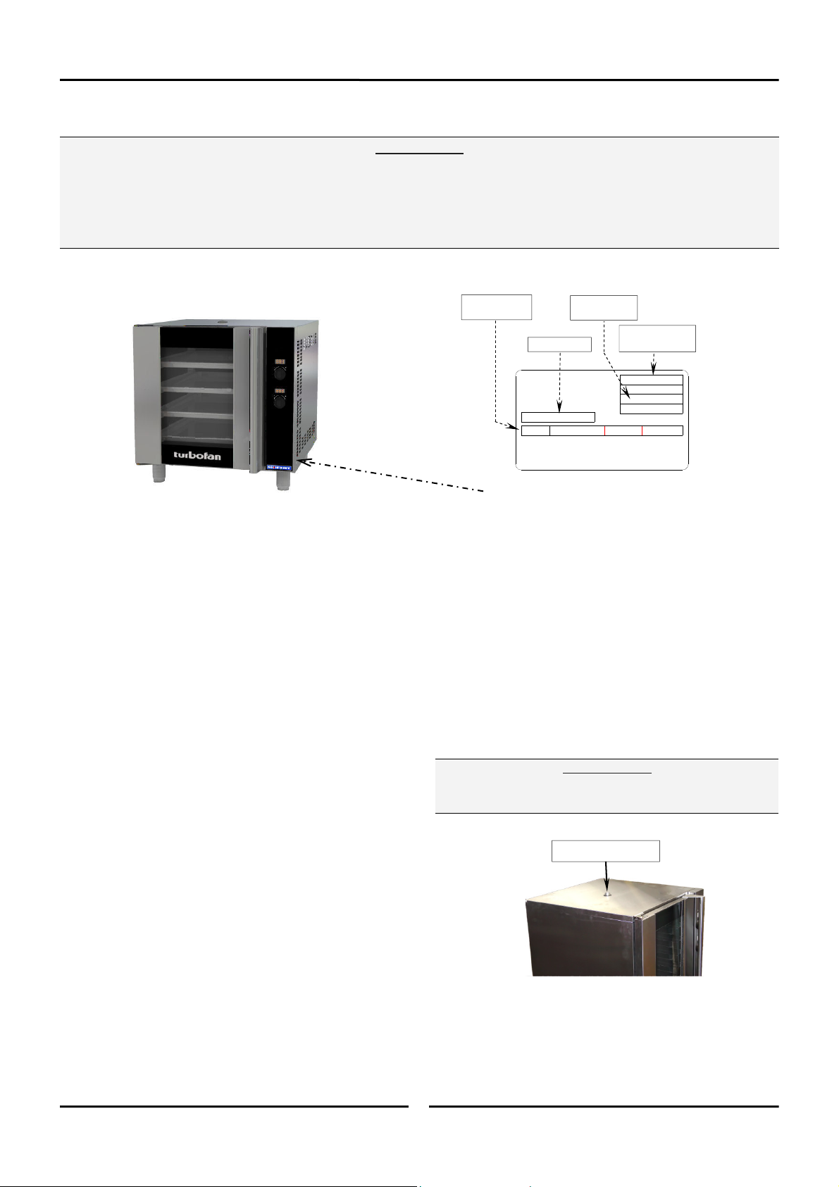
Unpacking
Electrical Power
Rating
Technical Data Plate - Data and Location
Clearances
Current Draw
MOFFAT LIMITED
CHRISTCHURCH ( NEW ZEALAND )
A @ V a.c.
12.0 115
28.0 A @ 230 V a.c.
1P+N+E
THIS APPLIANCE SHALL BE INSTA LLED IN ACCORDANCE WITH CURRENT
REGULATIONS AND USED ONLY I N A WELL-VENTILATED SPACE. REFER TO THE
INSTRUCTIONS BEFORE INSTALLING AND USING THIS APPLIANCE.
Oven
Serial Number
Model Number
MODEL
E22M3
*****
USE22M3
CODE
*******
SERIAL
xxxxxx
LOT yywwxxx
*******
V a.c. Hz kW
110-120 50-60 1.5
220-240 V a.c.
THIS APPLIANCE MUST BE EARTHED / GROUNDED
50/60 Hz
(example only)
Oven
6.5
1. Remove all packaging and transit protection including
all protective plastic coating from the exterior stainless
steel panels.
2. Check the oven and supplied parts for damage. Report
any damage immediately to the carrier and distributor.
3. Check that the following parts have been supplied with
your oven:-
4 x Leg Adjustable.
Water Connection Elbow.
4. Report any deficiencies to the distributor who supplied
your oven.
5. Securely fit the 4 legs supplied with the oven.
6. Check that the available electrical supply is correct to
that shown on the Technical Data Plate located on the
front right hand side panel.
• Refer to ‘Specifications’ section, ‘Oven
Specifications Tables’.
Location
1. Position the oven in its approximate working position.
2. The unit should be positioned so that the control panel
and oven shelves are easily reachable for loading and
unloading.
To ensure correct ventilation for the motor and controls,
the following minimum installation clearances are to be
adhered to:-
Top 200 mm / 8”.
Rear 75 mm / 3”.
Left-hand side 75 mm / 3”.
Right-hand side 75 mm / 3”.
NOTE: Fixed installations require at least 500 mm -
20” clearance at the right hand side of oven for
service access.
Important:
The vent located on the top of the oven must NOT be
obstructed.
Oven Vent Location
Stand Mounted Oven
For ovens that are to be mounted to a stand, the oven feet
are used to level the oven on the stand. Refer to the
instructions supplied with separately ordered stands for
mounting details.
4

Installation
Electrical Connection
Warning
This oven must be earthed / grounded.
Each oven should be connected to an adequately protected
power supply with an appropriate three wire power cord.
An isolation switch must be mounted adjacent to, but not
behind the oven and must be readily accessible to the
operator. This switch must be clearly marked and readily
accessible in case of fire.
Check the electricity supply is correct to as shown on the
Technical Data Plate on the front right hand corner of the
oven side panel.
NOTE: All electrical connections must only be carried
out by a suitably qualified person.
1. Remove oven right hand side panel.
2. Bring the supply cable up through the grommet at the
back of oven and through the compression gland on the
electrical switchgear panel.
3. Connect the mains supply to the appropriately marked
terminals on the terminal block.
Water Connection - Optional
main oven operation)
(not required for
Commissioning
Before leaving the new installation;
Check the oven functions in accordance with the
operating instructions specified in the ‘Operation’
section of this manual.
Ensure that the operator has been instructed in the areas
of correct operation and shutdown procedure for the
appliance.
NOTE: If for some reason it is not possible to get the
appliance to operate correctly, turn off the
power supply at the mains supply and contact
the supplier of this appliance.
1. If the manual addition of water into the oven for
humidification or steaming effect on baked product is
required, the unit’s water connection can be used.
2. A cold water supply should be fitted to the water inlet
(¾” BSP hose connection) which is located on the rear
of the right hand side of the oven.
3. Alternately, a connection elbow and sealing washer is
supplied with this unit for direct connection of a ½” ID
hose, and is recommended for easy installation and
service.
4. Connect to the water supply.
- Max Inlet Pressure 80psi / 550kPa.
5. Turn ‘On’ the water supply and check for leaks.
Positioning and Levelling of Oven
1. Correctly locate the oven into its final operating position
and using a spirit level, adjust the oven feet so that the
oven is level and at the correct height.
Initial Start-Up
Before using the new oven;
1. For first time use of the oven, operate the oven for
about 1 hour at 200°C / 400°F to remove any fumes or
odours which may be present.
2. Please refer to the Operation Section of this manual for
details on how to correctly operate and shutdown the
oven.
5
 Loading...