

Mobile Communications BRBUZ81975 User Manual
Stealth Series Dual Band Booster Amplifiers
®
BRB Stealth Z1
User Manual
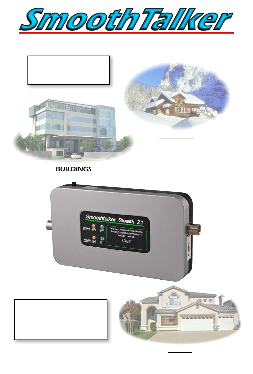
COTTAGES
BUILDINGS
Increases your Cellular and PCS Band
Signals, expands your service coverage
area, enhances voice call quality and
signicantly increases Data speeds.
HOMES

Table of Contents
Kit Type Configurations..............................................................................3
Optional parts................................................................................................3
Antenna and Booster Installation..........................................................4
Installation Illustrations...............................................................................5
Control panel ................................................................................................6
LED lights - Outside signal level/RX power..........................................6
Frequently asked questions......................................................................7
Troubleshooting guide.............................................................................7
Inside Antennas ............................................................................................8
Outside Antennas ........................................................................................8
Splitters/Power Dividers.............................................................................8
Extention Cables ..........................................................................................9
Specifications..............................................................................................11
Glossary of terms.......................................................................................12
FCC Information..........................................................................................12
Warranty.....................................................................................................12
This is a CONSUMER device
BEFORE USE, you MUST REGISTER THIS DEVICE with your wireless provider and
have your provider’s consent. Most wireless providers consent to the use of
signal boosters. Some providers may not consent to the use of this device on
their network. If you are unsure, contact your provider.
You MUST operate this device with approved antennas and cables as specified
by the manufacturer.
Antennas MUST be installed at least 20 cm (8 inches) from any person.
You MUST cease operating this device immediately if requested by the FCC or a
licensed wireless service provider.
WARNING. E911 locator information may not be provided or may be inaccurate
forcalls served by using this device.
To comply with FCC rules the use of this device in any building is for personal use only.
Pg. 2

Package Contents
BRBZ Series
(Individual Kit Configuration Parts Included Vary By Model)
Typical Configuration
Outdoor Antenna
Main Booster Unit
NOTE : Your model may ship with different antennas.
Optional Parts
Indoor Antenna
AC/DC Power Supply
Co-Ax Cables
RF Splitter/Power Divider
2” 11” 14” 26”
Avaliable Antennas
Co-Ax Adapters
Antenna Pole Mount Kit
Pg. 3

Antenna and Booster Installation
Donor Antenna: (outdoor signal antenna)
a) Location: There are three choices. fig. 2, 3, 4.
The choice of donor antenna location depends on the signal strength at the donor antenna
location. Use your phone to determine if signal at your chosen location is adequate. Better
signal level at the donor antenna location equals larger indoor coverage area.
b) Directional Donor Antenna: if using an optional directional donor antenna, point the
antenna toward the desired tower. If the location of the desired tower is not known, initiate a
phone call and use the signal indicator on your phone after the booster is operational, while
turning the donor antenna, to determine optimum donor antenna direction for maximum
signal strength.
c) Omni-directional Donor Antenna: if using an omni-directional donor antenna, it is
recommended that it is placed as far as possible from the inside antenna, usually, ‘outside pole
mount’ is recommended (Fig. 4). Use of omni-directional antennas will require more
separation distance compared to directional antennas. Fig. 1
Distribution Antenna: (indoor signal antenna)
a) Location: There are three choices. fig. 2, 3, 4.
The choice of donor antenna location depends on the area to be covered.
b) Directional Distribution Antenna: it is recommended that directional antennas
are oriented in a fashion that is back to back of each other Fig. 1
c) Omni-directional Distribution Antenna: it is important that omni-directional
antennas are separated as far apart as possible from each other. Use of omni-directional
antennas will require more separation distance compared to directional antennas
d) Splitting Indoor Signal: it is possible to use more than one indoor antenna to
cover areas that are separated by walls or floors by using antenna splitters or
power dividers, however splitters have a level of signal loss (3dB) and the added cable run
will also have signal loss, therefore the coverage area will be diminished. As a general rule, if
outside signal is good, splitting signal to more than one
distribution antenna results in reasonable coverage.
If outside signal is poor or marginal, splitting signal to more than one distribution antenna
results in decreased coverage for both distribution antennas.
Use only genuine SmoothTalker splitters. Contact your dealer or www.smoothtalker.com
Amplifier/Booster Location:
Install the repeater in a location that has proper ventilation, away from excessive heat and
moisture.
WARNING:
Make sure all cables have a good connection and are connected to the corresponding
antenna port on the Booster.
DO NOT APPLY POWER or turn on the power switch on the Amplifier/Booster
before all cables and antennas are connected.
Connection and Start Procedure:
Antenna connections must be snug and hand tight, ‘Do Not Use Pliers or Wrench’.
Connect the cable from outdoor antenna to RF port (antenna connector) labeled “Outdoor
Antenna”. Connect cable from indoor antenna to RF port labeled “Indoor Antenna”.
Connect supplied AC/DC power supply to the amplifier and plug it into power source.
Turn on the power switch on the Amplifier/Booster.
Pg. 4
 Loading...