

Page 1

Stealth X2 Dual Band Boosters
BUILDINGS
HOMES
®
COTTAGES
Page 2

Stealth X2 Dual Band Boosters
Table of Contents
Features ......................................................................3
Specifications .............................................................3
Package contents ...................................................4
Optional Parts ............................................................4
Antenna and Booster Installation .....................5
Installation Illustrations .........................................6
Control panel ...........................................................7
LED lights - Outside signal level/RX power .....7
Gain level ..................................................................8
Manual gain control ..............................................8
LED lights - Gain level ...............................................9
Tech support .............................................................9
Frequently asked questions .............................10
Troubleshooting guide ......................................10
Inside Antennas .....................................................11
Outside Antennas ................................................11
Extention Cables ....................................................12
Splitters/Power Dividers ......................................12
Specifications .........................................................13
Glossary of terms .................................................14
FCC information ....................................................14
Warranty ..................................................................14
®
Pg. 2
Page 3
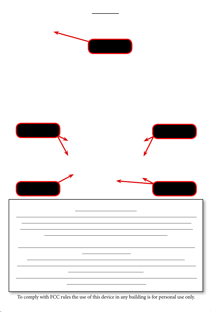
Features
Pwr ON/OFF
Switch & LED
Receive Signal Power Level
(Orange LED)
Master Control
Switch
Gain Level
Indicator (LED)
Control Buttons for:
Manual Gain - 2dB steps &
LED Brightness Level
This is a CONSUMER device
BEFORE USE, you MUST REGISTER THIS DEVICE with your wireless provider and
have your provider’s consent. Most wireless providers consent to the use of
signal boosters. Some providers may not consent to the use of this device on
their network. If you are unsure, contact your provider.
You MUST operate this device with approved antennas and cables as specified
by the manufacturer.
Antennas MUST be installed at least 20 cm (8 inches) from any person.
You MUST cease operating this device immediately if requested by the FCC or a
licensed wireless service provider.
WARNING. E911 locator information may not be provided or may be inaccurate
forcalls served by using this device.
To comply with FCC rules the use of this device in any building is for personal use only.
Pg. 3
Page 4

Package Contents
NOTE: Antennas and cables may be different than shown
depending on your kit configuration
Booster
Outside Antenna
Inside Antenna
Extension Cable
Co-Ax Cables
Omni Directional
Antennas
Power Supply
Optional Parts
Antenna Pole Mount Kit
RF Splitter/Power Divider Co-Ax Adapters
Pg. 4
Page 5

Antenna and Booster Installation
Donor Antenna: (outdoor signal antenna)
a) Location: There are three choices. fig. 2, 3, 4.
The choice of donor antenna location depends on the signal strength at the donor antenna
location. Use your phone to determine if signal at your chosen location is adequate. Better
signal level at the donor antenna location equals larger indoor coverage area.
b) Directional Donor Antenna: if using a directional donor antenna
supplied in the kit (Part# SEMD1), point the antenna toward the desired tower. If the location of the desired tower is not known, initiate a phone call and use the signal indicator on
your phone after the booster is operational, while turning the donor antenna, to determine
optimum donor antenna direction for maximum signal strength.
c) Omni-directional Donor Antenna: if using an omni-directional donor antenna, it is
recommended that it is placed as far as possible from the inside antenna, usually, ‘outside pole
mount’ is recommended (Fig. 3). Use of omni-directional antennas will require substantial
separation distance compared to directional antennas. Fig. 1
Distribution Antenna: (indoor signal antenna)
a) Location: There are three choices. fig. 2, 3, 4.
The choice of donor antenna location depends on the area to be covered.
b) Directional Distribution Antenna: it is recommended that directional antennas
are oriented in a fashion that is back to back of each other Fig. 1
c) Omni-directional Distribution Antenna: it is important that omni-directional
antennas are separated as far apart as possible from each other. Use of omni-directional an-
tennas will require substantial separation distance compared to directional antennas. Fig. 1
d) Splitting Indoor Signal: it is possible to use more than one indoor antenna to
cover areas that are separated by walls or floors by using antenna splitters or
power dividers, however splitters have a level of signal loss (3dB) and the added cable run
will also have signal loss, therefore the coverage area will be diminished. As a general rule, if
outside signal is good, splitting signal to more than one
distribution antenna results in reasonable coverage.
If outside signal is poor or marginal, splitting signal to more than one distribution antenna
results in decreased coverage for both distribution antennas.
Use only genuine SmoothTalker splitters. Contact your dealer or www.smoothtalker.com
Amplifier/Booster Location:
Install the repeater in a location that has proper ventilation, away from excessive heat and
moisture.
WARNING:
Make sure all cables have a good connection and are connected to the corresponding
antenna port on the Booster.
DO NOT APPLY POWER or turn on the power switch on the Amplifier/Booster
before all cables and antennas are connected.
Connection and Start Procedure:
Antenna connections must be snug and hand tight, ‘Do Not Use Pliers or Wrench’.
Connect the cable from outdoor antenna to RF port (antenna connector) labeled “Outdoor
Antenna”. Connect cable from indoor antenna to RF port labeled “Indoor Antenna”.
Connect supplied AC/DC power supply to the amplifier and plug it into power source.
Turn on the power switch on the Amplifier/Booster.
Pg. 6
Pg. 5
Page 6
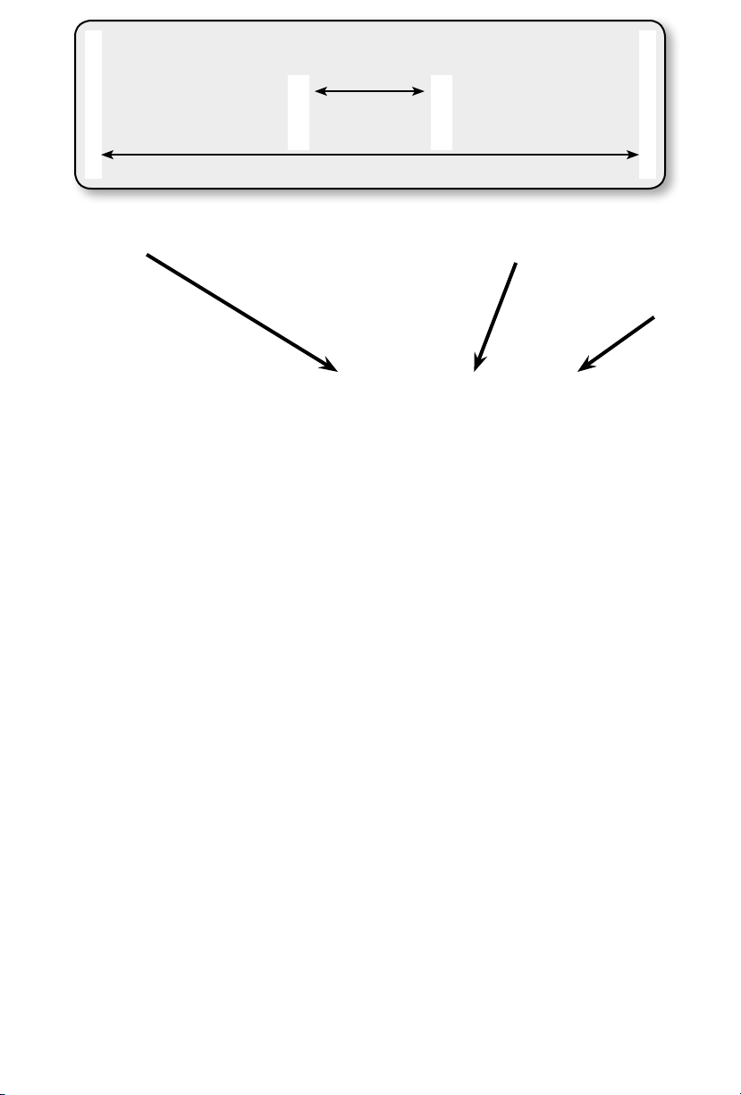
Directional antennas separation distance - Close
Omni directional antennas separation distance - Far
Distribution Antenna
(pointed indoors)
Fig. 1
Booster
Donor Antenna
(pointed outdoors)
Fig. 2
Pg. 6
Fig. 3
Fig. 4
Pg. 7
Page 7
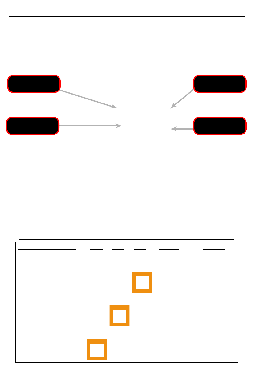
Control Panel: Understanding the Control Panel and LED lights
General: Mobile networks, phones and data devices operate in two frequency bands
(800Mhz & 1900Mhz). The Stealth Booster will amplify signals in both bands if they are
present. The band that the phone or cellular data device will transmit (TX) and receive (RX)
on is determined by the cellular provider and cannot be chosen by the user. The booster
LED lights will indicate outside signal level and booster gain. The ‘Master Control’ button
on the control panel will allow the user the option to increase gain, decrease gain or shut
off one or both of the frequency bands.
Receive Signal Power Level
(Orange LED)
Master Control
Switch
Gain Level
(Green LED)
Control Buttons for:
Manual Gain - 2dB steps
LED Light Brightness: the user can control the LED brightness of all LED lights by pushing
the up or down arrows on the control panel.
Receive Signal Power Level LED lights: three orange LED lights for each frequency band
receive signal (RX) power being amplified by the booster and transmitted into the building.
This indicator is affected by two things : the outside signal and attenuation that is applied
by the user or the automatic controls of the booster. The highest level signal being displayed by the booster lights can belong to any service provider, not necessarily your service
provider. Note: if attenuation (gain reduction) has been applied by the automatic controls
of the booster or by the user, you may see low signal indication on the booster LED lights
even though the true outside signal is strong.
Outside Signal Level/RX Power LED Indicator Light States
Outside Signal Level LED LED1 LED2 LED3 Flashing RX Power
3 Lights Solid ON No Excellent
2 Lights Solid ON,
3rd Light Flashing
2 Lights Solid ON,
3rd Light OFF
1 Light Solid ON,
2nd Light Flashing
1 Light Solid ON,
2nd & 3rd Lights OFF
1 Light Flashing,
2nd & 3rd Lights OFF
Yes
No
Yes
No
Yes
Good
Fair
Fair to Low
Low
Very Low
Pg. 8 Pg. 7
Page 8

Gain Level: Understanding the Control Panel and LED lights
General: Four green LED lights for each frequency band will indicate the level of amplification
that is being applied by the Booster to the receive (RX) signal and transmit (TX) signal. Gain is
applied to both RX and TX signals. Normally all four green LED will be solid on. If any green
LED lights are flashing or off, it is an indication that gain has been reduced. There are four
events that will cause the green LED lights to turn off or flash.
1) Shutdown:
a) Automatic shutdown will occur in one band or both bands if antennas are placed too close
to each other and the ‘Automatic Oscillation (feedback) Suppression’ function cannot eliminate
the oscillation. TX and RX gain will be turned off completely in the frequency band where oscillation cannot be suppressed.
b) Manual shutdown can also be achieved in one or both frequency bands by the user.
2) Oscillation (feedback) Suppression:
The booster will automatically apply attenuation (reduce gain) to suppress oscillation (feedback). This function is automatic and cannot be manually overridden.
3) RX High Power Control:
The booster will automatically apply attenuation (reduce gain) if RX power is too high. This
function is automatic and cannot be manually overridden.
4) Manual Attenuation:
Gain can be increased or decreased manually by the user in 1dB steps over a range of 35 dB
for each frequency band, however, the user will not be able to reduce attenuation that has
been applied by the automatic oscillation suppression function or by the automatic high power
control function in order to protect both, the cellular tower and the booster.
Manual Gain Control
The master control button has 3 functions which cycle every 3 times pressed as follows:
1) 800mhz manual gain control Press once. The 3 orange LED lights for the 800 mhz band
will flash together. Use up or down arrows to adjust gain in this frequency band as desired.
Each push of the up or down button will adjust 1 dB of gain. Total manual adjustment range
is 35 dB. Adding more than 35 dB of attenuation will shut down the frequency band. Quick
shutdown of the frequency band can also be achieved by holding the down arrow. When the
frequency band shuts off all of the orange and green LED lights for that frequency band will
flash every 2 seconds.
2) 1900mhz manual gain control Press second time. The 3 orange LED lights for the 1900
mhz band will flash together. Use up or down arrows to adjust gain in this frequency band if
desired. Each push of the up or down button will adjust 1 dB of gain. Total manual adjustment
range is 35 dB. Adding more than 35 dB of attenuation will shut down the frequency band.
Quick shutdown of the frequency band can also be achieved by holding the down arrow.
When the frequency band shuts off all of the orange and green LED lights for that frequency
band will flash every 2 seconds.
3) Manual gain LED display Press third time to display the LED status of your inputed manual
gain settings then power the booster OFF/ON for manual settings to take effect. Each time you
cycle to this 3rd setting you will see your inputed manual gain settings displayed on the LEDs.
Note: the booster will remember manual settings through power on and off conditions. If you
want to return the booster to ‘Fully Automatic Mode’ you must push and hold the master control button (approximately 3 to 5 seconds) until you see all 800mhz lights flash once from left
to right followed by 900mhz lights flash once from left to right. Power the booster OFF and
then ON for ‘fully automatic mode’ to take effect.
Important:
a) for manual settings to take effect, the booster must be powered OFF and then ON.
b) manual settings cannot override the automatic functions of oscillation and high power
controls. This means that if you are trying to set a gain level higher than the automatic control
functions allow, the manual gain settings will be limited by the automatic control functions.
Pg. 9Pg. 8
Page 9
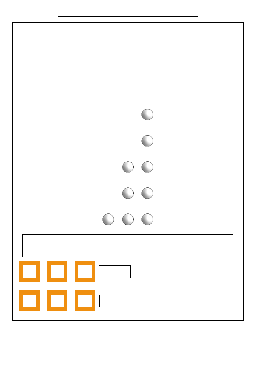
Gain Level LED Indicator Light States
There are four green LED lights for each freq. band (800Mhz & 1900Mhz).
Each LED represents 10dB of attenuation that is displayed as 1 to 4 flashes and solid ON.
Gain Level LED Status Flashing Pattern Attenuation
LED1 LED2 LED3 LED4
(gain reduction)
4 Lights Solid ON None
4 Times
3 Lights Solid ON,
4th Light Flashing
3 Lights Solid ON,
4th Light OFF
2 Lights Solid ON,
3th Light Flashing
2 Lights Solid ON,
3rd & 4th Light OFF
1 Light Solid ON,
2nd Light Flashing
1 Light Solid ON
3 Times
2 Times
1 Times
None
4 Times
3 Times
2 Times
1 Times
None
4 Times
3 Times
2 Times
1 Times
None
0 dB
2 dB
4 dB
6 dB
8 dB
10 dB
12 dB
14 dB
16 dB
18 dB
20 dB
22 dB
24 dB
26 dB
28 dB
30 dB
Pg. 10
More then 35db of attenuation the Freq band will shut down and
it’s LED lights will flash together every 2 seconds
800mhz
1900mhz
Tech Support: [email protected]
Live tech Support: 9:00 am - 6:00 pm EST Mon - Fri
Toll free1-877-726-3444
Pg. 9
Page 10
Frequently Asked Questions
My booster is powered, running and the lights are on but my signal did not improve. Why?
Check your antenna connections and make sure they are snug. Also make sure that the external
and internal antennas are connected to corresponding antenna ports of the booster.
Should the booster get hot? Normal operation temperature for the booster is approximately 109°
F, or 43° C. This will feel warm to the touch.
Will the booster improve Voice and Data signals? Yes.
How large should my inside coverage area be? Coverage area is dependent on two factors; the
booster’s gain and the signal level at the outside antenna. It is possible to cover a large area with a
low gain booster if the outside signal is excellent, conversely, it is possible to have
relatively small coverage area with a high gain booster if the signal outside is really poor.
How do I increase my indoor coverage area? If your inside coverage area is inadequate, try to
move your external antenna to a location with better signal. If antenna location is optimized the
coverage area is still too small, use a higher gain booster.
Will the booster boost signals from service providers other than mine? Yes. Smoothtalker
Stealth series boosters are wideband RF amplifiers that will improve all Cellular and PCS signals
in your area.
Why does my friend’s phone show better signal than mine? Your friend’s phone is probably
using a different service provider that has a tower closer to your location than your service
provider. For best indoor coverage, make sure that your outside antenna is pointing at your
service provider’s tower.
Can I leave my booster on continuously? Yes.
Can I leave my booster on during a lightning storm? To be 100% sure that lighning will not
damage the booster, you must unplug it from the wall and disconecct the external antenna from
the booster. If you must keep connected during lightning you can use a lightning arrestor on the
antenna and high quality surge protector on the power supply, however, Smoothtalker warranty
does not cover lightning damage.
I need more cable length. What do I use? The only extention cables that are FCC approved for
use with this booster are listed on page 13.
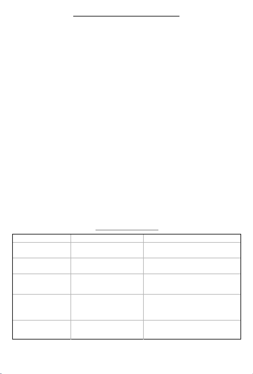
Troubleshooting Guide
Condition
Automatic Shutdown.
Manual Shutdown.
Oscillation (feedback)
Suppression:
Automatic cannot be manually
overridden.
High power control due to
High RX signal (signal from
tower):
Automatic cannot be
manually overridden.
Manual Attenuation. One or more green LED solid ON, one
Orange and green LED ash
simultaneously every 2 secs in the freq.
band that has been shutdown.
Orange and green LED ash
simultaneously every 2 secs in the freq.
band that has been shutdown.
One or more green LED solid ON, one
green LED ashing or OFF.
One or more green LED solid ON, one
green LED ashing or OFF.
green LED ashing or OFF.
Pg. 10
LED indicators Action
Separate antennas and/or re-orient directional
antennas (back to back) and power OFF/ON the
booster.
Use control panel to increase gain to the desired level
in the chosen freq. band and power OFF/ON the
booster.
Gain has been reduced to suppress oscillation (feedback). Separate antennas and/or re-orient directional
antennas (back to back) and power OFF/ON the
booster.
Gain has been reduced to suppress high RX signal:
a) Directional donor (outside) antenna: turn to point
away from tower.
b) Omni antenna: change to a location with lower
signal.
Use control panel to increase or decrease gain to the
desired level in the chosen freq. band and power
ON/OFF the booster to set.
Pg. 11
Page 11
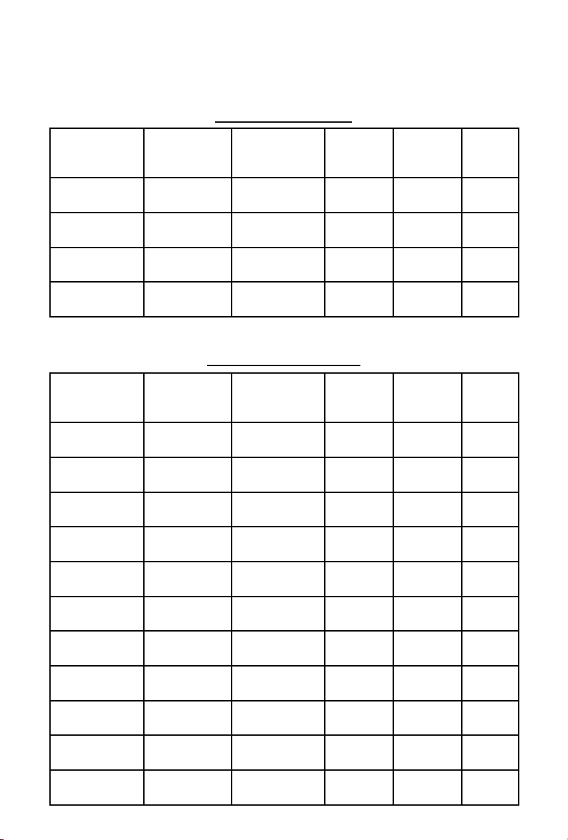
FCC Rules specify that all approved antennas, cables and accessories to
be used with this booster are to be listed in this manual. e approved
accessories are listed below.
Inside Antennas
Antenna Part # Description Cable
SEMD1XL Inside antenna
SEMOXL Inside antenna
SEMOX Inside antenna
SEMR1 Inside antenna
18 .
SEMRC205
18 .
SEMRC205
10 .
SEMRC105
Direct to
booster
Minimum
Cable loss
(dBi)
-2 8.14 6.14
-2 0 -2.14
-2 0 -2.14
0 0 2.14
Maximum
Antenna
Gain (dBi)
Net gain
(dBi)
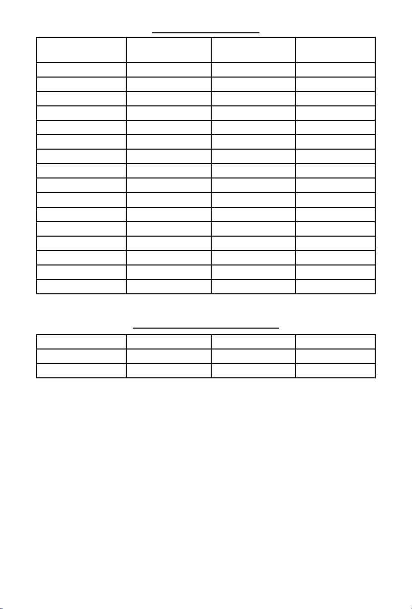
Outside Antennas
Antenna Part # Description Cable
SEMD1XL
SEMDA2XL
SEMOXL
SEM2THX
SEM11THX Outside
SEM14THX Outside
SEM26THX Outside
SEM2THXL Outside
SEM11THXL Outside
SEM14THXL Outside
SEM26THXL Outside
Outside
antenna
Outside
antenna
Outside
antenna
Outside
antenna
antenna
antenna
antenna
antenna
antenna
antenna
antenna
18 .
SEMRC205
18 .
SEMRC205
18 .
SEMRC105
14 .
SEMRC105
14 .
SEMRC105
14 .
SEMRC105
14 .
SEMRC105
25 .
SEMRC105
25.
SEMRC105
25 .
SEMRC105
25 .
SEMRC105
Minimum
Cable loss
(dBi)
-2 8.14 6.14
-2 9.14 7.14
-2 0 -2.14
-1.5 2.14 0.64
-1.5 5.14 3.64
-1.5 5.14 3.64
-1.5 7.14 5.64
-2.75 2.14 -0.61
-2.75 5.14 2.39
-2.75 5.14 2.39
-2.75 7.14 4.39
Maximum
Antenna
Gain (dBi)
Net gain
(dBi)
Pg. 11
Page 12
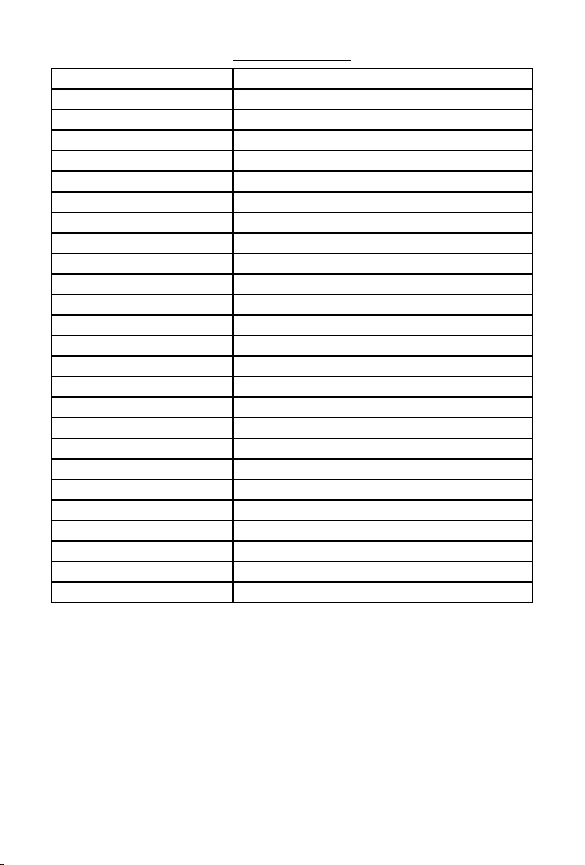
Extension Cables
Cable Part # Description Cable Minimum Cable
loss (dB)
SEMRCBXmaXfe10 extension cable 10 . SEMRC205 -1
SEMRCBXmaXfe20 extension cable 20 . SEMRC 205 -2
SEMRCBXmaXfe30 extension cable 30 . SEMRC205 -3
SEMRCBXmaXfe40 extension cable 40 . SEMRC205 -4
SEMRCBXmaXfe50 extension cable 50 . SEMRC205 -5
SEMRCBXmaXfe60 extension cable 60 . SEMRC205 -6
SEMRCBLXmaXfe10 extension cable 10 . LMR400 -0.6
SEMRCBLXmaXfe20 extension cable 20 . LMR400 -1.2
SEMRCBLXmaXfe30 extension cable 30 . LMR400 -1.8
SEMRCBLXmaXfe40 extension cable 40 . LMR400 -2.4
SEMRCBLXmaXfe50 extension cable 50 . LMR400 -3
SEMRCBLXmaXfe60 extension cable 60 . LMR400 -3.6
SEMRCBLXmaXfe70 extension cable 70 . LMR400 -4.2
SEMRCBLXmaXfe80 extension cable 80 . LMR400 -4.8
SEMRCBLXmaXfe90 extension cable 90 . LMR400 -5.4
SEMRCBLXmaXfe100 extension cable 100 . LMR400 -6
Splitters/Power Dividers
Part # Description Insertion loss (dB) Net gain (dB)
ADCSP1 2-way power divider -3 -3
ADCSP3 3-way power divider -3 -3
Pg. 12
Page 13
Specifications
Operational Bands 800MHz Cellular and 1900MHz PCS
Impedance 50 Ohms
TX Output Power 29.9 dBm EIRP
RX Output Power 11.0 dBM EIRP
Oscillation Control (Automatic) 35 dB in 1db steps
Oscillation Control Timing < 1 sec
RX High Power Control Dynamic up and down < 50 milliseconds
TX High Power Control Dynamic up and down < 50 milliseconds
Current Draw @ 12V 0.5 Amp - 0.8 Amp
Operating Voltage 6V
Noise Figure < 5dB
Operating Temperature -32F to +85F
Outside Antenna Connector MCT Male
Inside Antenna Connector MCT Male
Dimensions 6.25x3.5x1.125 inches
Weight 1.0 Lb
FCC ID S4RBRB81975
Model Maximum Gain
BRBX2-72 72dB
BRBX2-70 70dB
BRBX2-68 68dB
BRBX2-65 65dB
BRBX2-62 62dB
BRBX2-60 60dB
BRBX2-58 58dB
BRBX2-55 55dB
Pg. 13
Page 14

Glossary of Terms
Attenuation: the reduction of the RF signal usually measured in dB. Attenuation is the opposite
of Gain. Increasing attenuation has the same effect as turning down the volume control of a
radio or stereo speaker.
Booster: also known as: RF amplifier, repeater or signal enhancer.
dB: short form for decibel. Unit of measure for RF signal gain or attenuation.
Directional antenna: an antenna designed to focus its energy mostly in one direction.
Distribution antenna: internal antenna used to distribute signal to the interior of a
building or structure.
Donor Antenna: outside antenna used to provide signal from outside to inside.
Frequency band: the operational frequency range of the Smoothalker booster and the cellular
network frequencies that are amplified. These are commonly referred to as the ‘Cellular Band’
(824-894 Mhz) and the ‘PCS Band’ (1850-1990 Mhz).
Gain: the increase of the RF signal usually measured in dB. Gain is the opposite of
Attenuation. Increasing gain has the same effect as turning up the volume control of a radio or
stereo speaker.
LED: Light Emitting Diode.
Omni-directional antenna: an antenna designed to radiate its energy equally in all
directions.
Oscillation: term to describe a feedback loop. This occurs when the signal from one
antenna reaches the other antenna and the booster amplifies the signal creating a loop. This is
the same effect as the squeal one hears when a speaker is brought close to a microphone.
RF: Radio Frequency.
RX: ‘receive signal’ originating at a base station or tower.
Splitter/Power Divider: a component with input and output connectors that will allow one
originating signal to be split and distributed to two or more antennas.
TX: ‘transmit signal’ originating from a cellular phone or data device.
FCC Part: §15.21 Information to Users
“The users manual or instruction manual for an intentional or unintentional radiator shall
caution the user that changes or modifications not expressly approved by the party
responsible for compliance could void the user’s authority to operate the equipment.
In cases where the manual is provided only in a form other than paper, such as on a
computer disk or over the Internet, the information required by this section may be
included in the manual in that alternative form, provided the user can reasonably be
Please Note: Antenna should be positioned at least 8”(20cm) from all person/persons as per requirements
1-This booster is not user configurable. User changes are a violation under FCC rules and will void the user’s
expected to have the capability to access information in that form.”
“This device complies with part 15 of the FCC Rules.
Operation is subject to the following two conditions:
(1) This device may not cause harmful interference, and
(2) this device must accept any interference received, including
interference that may cause undesired operation.”
RF Exposure Warning
necessary to comply with the FCC MPE rules.
Notes:
authority to operate the equipment.
2-User changes changes or modifications will void warranty.
Warranty
Smoothtalker boosters are warranted against manufacturing defects for a period of two years from the date of purchase.
The original bill of sale is required for any warranty claims.
For warranty claim contact original dealer or smoothtalker.com
 Loading...