

Page 1
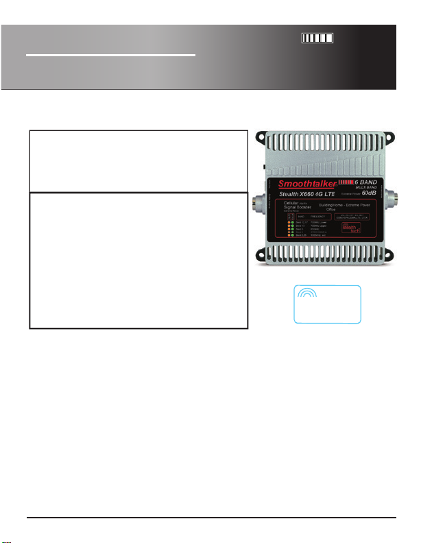
Stealth X6 4G LTE
Extreme Power Building Boosters
X660 X665 X672
Building
6 BAND
MULTI BAND
60 -72dB
User Manual
Cellular
Signal Booster
GSM,HSPA,CDMA,LTE, LTE A
Band 12,17
Band 13
Band 5
Band 4
Band 2,25
In 2001 SmoothTalker produced the rst digital mobile cellular signal booster
in North America with FCC and ICAN approval. We continue to lead with the
Our dynamic adaptive proprietary algorithms make them very network friendly.
RX/TX
60-72dB
Extreme Power Building Booster
2G, 3G, 3G+, 4G, 4G+
MULTI BAND 60-72dB
6 BAND
700MHz Lower
700MHz Upper
850MHz
1700/2100MHz
1900MHz ext
most powerful and intelligent boosters in the world.
We call it STEALTH TECH technology.
BBUX6 Series
USA
model shown: BMUX660
stealth
tech
®
1-877-726-3444
Smoothtalker.com
Page 2
Contents
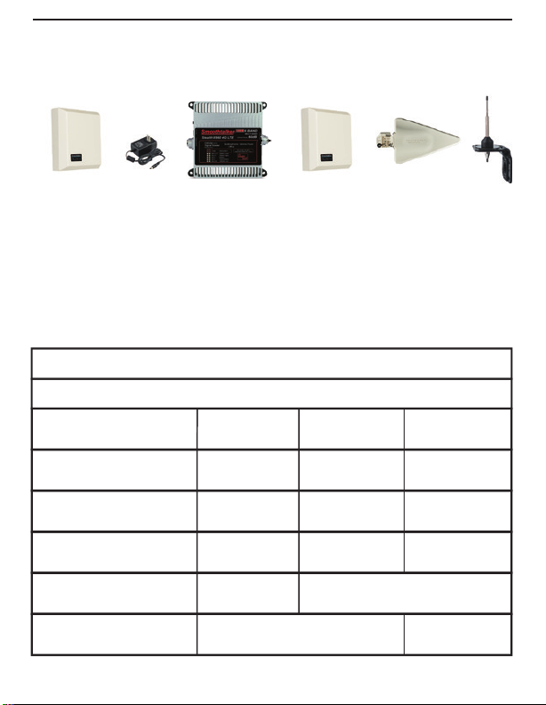
Contents
SEMDP1
Power supply
Cellular BoosterInside Antenna
Optional outside antennas
SEMDP1
SEMDA2 SEMO
NOTE:
Only one of the outside antennas is included in this kit (check model)
All kits include necessary brackets and co-axial cables for assembly.
It is normal for the booster to be quite warm during operation.
SPECIFICATIONS Stealth X6 4G LTE
Frequencies MHz
Model
Gain
Max Power TX: dBm
Max Power RX: dBm
Operating temp
Dimensions
2G, 3G, 3G+, 4G, 4G+, GSM, HSPA, CDMA, LTE, LTE A
700 upper 700 lower 850 1700/2100 1900
BBUX660
60
1.0
0.2
-22 F + 185 F
BBUX665
65
1.0
0.2
Power supply 120V AC/DC
L 5.0 x W 4.75 x H 1.25 (inch)
1
BBUX672
Weight
72
1.0
0.2
1.2 lbs
Page 3
Approved Equipment List
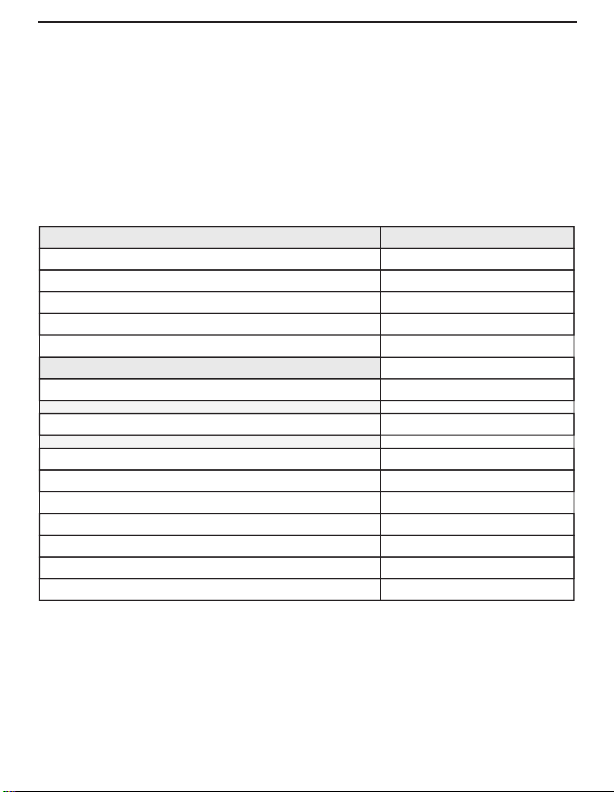
For specications of any of the Smoothalker FCC approved part numbers
listed below visit smoothtalker.com
FCC requirements prohibit the use of unauthorized Antennas, Cables,
and/or Coupling devices.
You MUST operate this device with approved antennas and cables as specied by
the manufacturer. Antennas MUST be installed at least 8 inches from any person.
You MUST cease operating this device immediately if requested by the FCC or a
licensed wireless service provider.
ANTENNA CABLES
ACX100X, ACX900X
CBXmaXfe10,20,30,40,50,60
CBNmaNfe10,20,30,40,50,60
CBGmaGfe 10,20,30,40,50,60,70,80,90,100
CBL4maL4fe 10,20,30,40,50,60,70,80,90,100
ANTENNAS
SEM2THL, 11THL, 14THL, 26THL series
SRP1X , SRP1XL
SRBL series
SEMD1 series
SEMDA2 series
SEMO series
SEMDP1 series
SEMDY series
SEMDYD series
SPLITTERS
ADCSPN2
ADCSPN3
ADCSPN4
ADCSPG2
ADCSPG3
ADCSPG4
2
Page 4

1) Installation:
Connect the inside antenna and the outside antenna as shown in Fig. 1, Pg. 4.
2) Outside antenna:
a) Place outside antenna outside of the house in the area that has the best signal.
b) If outside location is unavailable, place the outdoor antenna on a window with
the best signal.
3) Inside Antenna: Connect the inside antenna as shown in Fig. 1, Pg. 4.
4) Separation: Increase the distance of the outside and inside antenna as much as
possible to maximize coverage and avoid gain reduction.
5) Power: Connect the power supply to the booster and turn it on.
6) Coverage: Use your cell phone to determine if coverage is OK. If coverage is not
adequate, please look at the Green and Orange lights to determine if the
booster has automatically turned down its gain per LED Gain Chart on Pg. 6.
If so pls try to separate or move antennas as per explantion on Pg. 5/6.
Important: Use only the power supply included with the booster. Connecting any other power supply at any
time will result in damage to the booster and will void the warranty. Do not turn on the power switch until
ALL cables have been screwed or plugged into the booster or you can cause damage to the booster.
Optional Dual Inside Antenna Installation (Fig. 2)
(Additional parts required which are not included in Booster kit
1) Choose a splitter model for your needs. For 2 interior antennas use a 2 way
splitter and for 3 interior antennas use a 3 way splitter etc…
2) Mount the interior antennas in the areas which need cellular coverage
3) Evenly distribute the antennas throughout the oors and areas to cover
4) Turn on Booster unit and check signal strength improvement as needed
See page 2 for list of approved equipment )
If you need help pls contact [email protected] and we will help
you determine your cell tower location and get you setup.
[email protected] Tel: 1 877 726 3444
3
Page 5
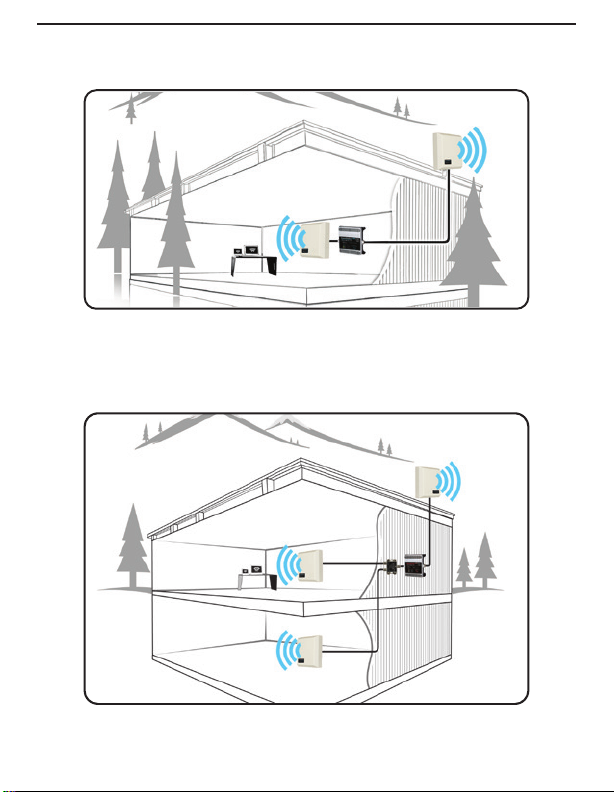
Typical Installation (Fig. 1 )
(All parts are included in Booster kit.)
Fig. 1
Optional Dual Inside Antenna Installation (Fig. 2 )
(Additional parts required which are not included in Booster kit.)
Fig. 2
4
Page 6

LED Lights Explanation and Troubleshooting
The LED lights on the booster face plate indicate the operating gain state
of the booster.
The Green and Orange lights indicate the gain status in each operating band
When Both Green and Orange LED's are “SOLID ON” it means that the booster
is operating normally with full gain (No Automatic Gain Reduction)
When one or both of the LEDS are ashing (Per the chart on Pg. 6)
it indicates that the gain has been automatically reduced due to either:
A) High RX outside signal level (close to cell tower)
B) Loop Oscillation, caused when the inside antenna is located too close to the
outside antenna.
Each ash indicates 3dB of gain reduction also known as gain attenuation.
For example: three ashes equals 9dB of attenuation.
Green LED indicates loop oscillation status. When ashing it means reduction of
gain. To improve you need to spread the distance between the inside and outside
antennas. If you spread them far enough away, the Green LED
will become SOLID ON.
Orange LED indicates RX (outside signal) status.
There are 5 Orange LED lights: 700 Mhz Lower, 700 Mhz Upper, 850 Mhz,
1700/2100 Mhz,1900 Mhz ext. LED ON state indicates that the RX (Receive Signal)
function of the band is functioning normally.
LED OFF state indicates that the band is shut down.
When Orange LED is ashing it indicates reduced gain also known as attenuation
of gain. You cannot prevent this condition. It means that the outside signal is very
strong and the booster has reduced it's gain in order to protect the closest cell
tower. If the cell tower which is close is the one you are using, then you can ignore
the gain reduction and you will still get enough signal strength to cover your area.
In this case this is the normal operating process.
If the close cell tower is not the one you are using, then you can try to relocate
your outside antenna away from this cell tower and face it or point it to the cell
tower you are using in order to get more gain.
If you need help pls contact [email protected] and we will help
you determine your cell tower location and get you setup.
[email protected] Tel: 1 877 726 3444
5
Page 7
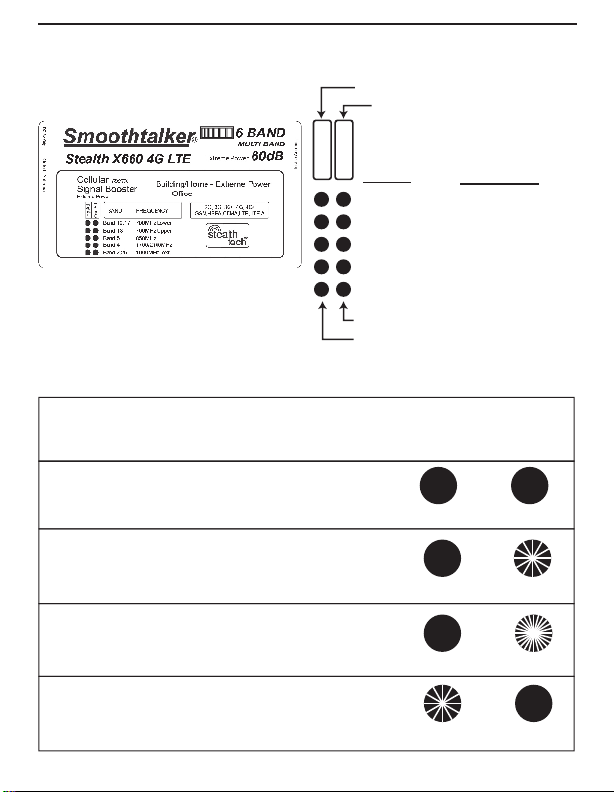
Understanding the LED Indicators
Hp Att
Osc Att
LED Lights Status Explanation
RX High Power Attenuation
Oscillation Attenuation
Band Frequency
Band 12, 17 700MHz Lower
Band 13 700MHz Upper
Band 5 850MHz
Band 4 1700/2100MHz
Band 2, 25 1900MHz ext
Green LED
Orange LED
Attenuation (Att)
Each ash indicates up to 3dB of gain reduction also known as gain attenuation.
For example: three ashes equals 9dB of attenuation.
Orange Solid ON = Full Gain & Green Solid ON = Full Gain
No Flashing = Full Gain
Orange Solid ON & Green Slow Flashing = Oscillation Att
Each Flash = up to 3dB of gain reduction
Orange O & Green Fast Flashing = Oscillation Shutdown
Fast Flashing = booster shutdown (pls troubleshoot)
Orange Slow Flashing & Green Solid ON = RX High Power Att
Each Flash = up to 3dB of gain reduction
ORANGE LED
High Power
ON ON
ON
SOLID ON
OFF
GREEN LED
Oscilation
SOLID ONSOLID ON
SLOW FLASHING
FAST FLASHING
ON/
SOLID ON SLOW FLASHING
6
Page 8
Operational description:
To comply with FCC NPS (Network Protection Standard) requirements: NPS and other
compliance/safeguard features for AGC and anti-oscillation have been implemented.
NPS and other compliance/safeguard features are defaulted to be “On” (in operation).
NPS and other compliance/safeguard features can not be eld recongured, disabled
or removed. This booster is not user programmable, does not need ne tuning or
adjustment, does not require professional installation.
The antenna for the device has a 10 meter above ground maximum antenna height
limitation when the device is used with a handset that covers the 1710-1755 MHz band.
Violation of this rule could be subject to potential FCC enforcement action for noncompliance.
This device may be operated ONLY in a xed location for in-building use.
This is a CONSUMER device.
BEFORE USE, you MUST REGISTER THIS DEVICE with your wireless provider and
have your provider’s consent.
Contact information for Booster registration:
Some providers have set up web-sites for booster registration. If you don’t see
your provider on this list, please contact your provider for information on how
to register your booster.
AT&T: https://securec45.securewebsession.com/attsignalbooster.com/
Verizon: http://www.verizonwireless.com/solutions-and-services/accessories/
register-signal-booster/
T-mobile: https://www.signalboosterregistration.com/
Sprint: https://www.sprint.com/legal/fcc_boosters.html
Us Cellular: http://www.uscellular.com/uscellular/support/fcc-booster-registration.jsp
WARNING. E911 location information may not be provided or may be inaccurate
for calls served by using this device.
Made in
North
America
FCC
Approved
1-877-726-3444
stealth
tech
Automatic power
control protects the
®
Cellular Network
Smoothtalker.com
 Loading...