

Page 1

1
PUMY
11
Outdoor units / Y series / PUMY-71·125VM
PUMY-71VM, PUMY-125VM
CONTENTS
1. Specifications
2. Capacity Tables
2-1 Correction by temperature
2-2 Correction by total indoor
2-3 Correction by refrigerant piping length
2-4 Correction at frosting and defrosting
2-5 Operation limit
3. Sound Levels
4. External Dimensions
5. Electrical Wiring Diagram
6. Refrigerant Circuit Diagram
·································································
······························································
············································
·············································
·······························································
··································································
····················································
··············································
·········································
And Thermal Sensor
···························
····························
2
4
4
6
8
9
9
10
11
13
15
Page 2

2
PUMY
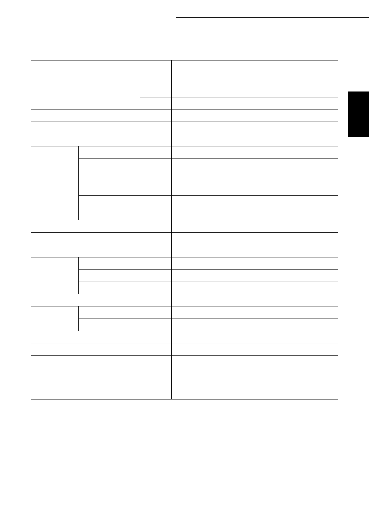
1. Specifications
Model name
Capacity
Power source
Power input
Current
Type ✕ Quantity
Fan
Compressor
Refrigerant / Lubricant
External finish
External dimension mm
Airflow rate
Motor output
Type
Motor output
Crankcase heater
kW ✻1
kcal/h
kW
A
3
m
/min
kW
kW
kW
PUMY-71VM
Cooling Heating
8.0 9.0
✻2
7,100 -
~/N 220-230-240V 50Hz / 208-23
3.50/3.63 3.65/3.53
17.5-16.7-16.0/18.1 18.2-17.4-16.0/17.6
Propeller fan ✕ 2
95
0.04 ✕ 2
Hermetic
2.6
-
R22/MS56
Steel plate painting with polyester powder
<MUNSELL 5Y8/1>
1200(H)✕900(W)✕320(+30)(D)
0V 60Hz
High pressure protection
Protection
devices
Refrigerant piping diameter Liquid / Gas
Indoor unit
Noise level
Net weight
Operating temperature range
Note: 1.Cooling/heating capacity indicates the maximum value at operation under the following condition.
Cooling ✻1 Indoor : 27˚CDB/19˚CWB Outdoor : 35˚CDB
Heating Indoor : 20˚CDB Outdoor : 7˚CDB/6˚CWB
Compressor / Fan
Inverter
Total capacity
Model / Quantity
dB<A>
kg
Indoor:15˚CWB ~ 24˚CWB
Outdoor:-5˚CDB ~ 46˚CDB
Pipe length : 7.5m Height difference : 0m
Internal thermal switch / Internal thermal switch
Over current protection, Overheat protection
50 ~ 130% of outdoor unit capacity
Model 20 ~ 80 / 1 ~ 4
Cooling ✻2 Indoor : 27˚CDB/19.5˚CWB Outdoor : 35˚CDB
Pipe length : 5m Height difference : 0m
3.0MPa
ø9.52 /ø15.88 (Flare)
52
93
Indoor:15˚CDB ~ 27˚CDB
Outdoor:-15˚CWB ~ 15.5˚CWB
2.Works not included : Installation/foundation work, electrical connection work, duct work, insulation work, power
source switch and other items not specified in this specification.
Page 3
3
PUMY
11
Outdoor units / Y series / PUMY-71·125VM
Model name
Capacity
Power source
Power input
Current
Type ✕ Quantity
Fan
Compressor
Refrigerant / Lubricant
External finish
External dimension mm
Airflow rate
Motor output
Type
Motor output
Crankcase heater
kW ✻1
kcal/h
kW
A
3
m
/min
kW
kW
kW
PUMY-125VM
Cooling Heating
14.0 16.0
✻2
12,500 -
~/N 220-230-240V 50Hz / 208-230V 60Hz
6.57/6.43 6.10/6.03
34.9-33.5-32.2/33.6 32.6-31.2-29.9/31.5
Propeller fan ✕ 2
90
0.06 ✕ 2
Hermetic
3.5
-
R22/MS32(N-1)
Steel plate painting with polyester powder
<MUNSELL 5Y8/1>
1280(H)✕1020(W)✕350(+30)(D)
High pressure protection
Protection
devices
Refrigerant piping diameter Liquid / Gas
Indoor unit
Noise level
Net weight
Operating temperature range
Note: 1.Cooling/heating capacity indicates the maximum value at operation under the following condition.
Cooling ✻1 Indoor : 27˚CDB/19˚CWB Outdoor : 35˚CDB
Heating Indoor : 20˚CDB Outdoor : 7˚CDB/6˚CWB
Compressor / Fan
Inverter
Total capacity
Model / Quantity
dB<A>
kg
Indoor:15˚CWB ~ 24˚CWB
Outdoor:-5˚CDB ~ 46˚CDB
Pipe length : 7.5m Height difference : 0m
Internal thermal switch / Internal thermal switch
Over current protection, Overheat protection
50 ~ 130% of outdoor unit capacity
Model 20 ~ 125 / 1 ~ 8
Cooling ✻2 Indoor : 27˚CDB/19.5˚CWB Outdoor : 35˚CDB
Pipe length : 5m Height difference : 0m
3.0MPa
ø9.52 /ø19.05
54
130
Indoor:15˚CDB ~ 27˚CDB
Outdoor:-15˚CWB ~ 15.5˚CWB
2.Works not included : Installation/foundation work, electrical connection work, duct work, insulation work, power
source switch and other items not specified in this specification.
Page 4
4
PUMY
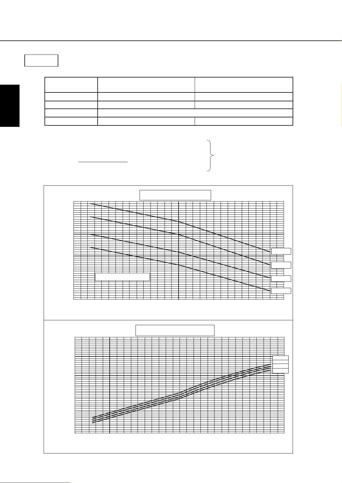
2-1. Correction by temperature
2. Capacity table
Cooling
• Standard Specifications
• Calculation
Capacity
Input
Source
kW
kW
V
Current A
Capacity' Capacity Ratio= ✕
Input Input Ratio'= ✕
Current'
Input'
=
✕✕1000
Source
1.20
1.10
Ratio
1.00
PUMY-71VM
8.0
3.50/3.63
17.5-16.7-16.0/18.1
❇ Capacity'
Input'
0.91 (:PUMY-71VM)
Current'
0.85 (:PUMY-125VM)
The Ratio of Cooling Capacity
PUMY-125VM
14.0
6.57/6.43
208-230V
34.9-33.5-32.2/33.6
After correction
22˚CWB
20˚CWB
0.90
0.80
-1001020304050
1.40
1.20
1.00
Ratio
0.80
0.60
0.40
-100 1020304050
Indoor Temperature(˚CWB)
The Ratio of Cooling Power Input
Outdoor Temperature (˚CDB)
Outdoor Temperature (˚CDB)
18˚CWB
16˚CWB
22˚CWB
20˚CWB
18˚CWB
16˚CWB
Page 5
Heating
5
PUMY
11
Outdoor units / Y series / PUMY-71·125VM
• Standard Specifications
Capacity
Input
Source
Current A
• Calculation
Capacity' Capacity Ratio= ✕
Input Input Ratio'= ✕
Current'
=
1.30
1.20
1.10
1.00
kW
kW
V
Input'
Source
PUMY-71VM
9.0
3.65/3.53
18.2-17.4-16.0/17.6
✕✕1000
0.91 (:PUMY-71VM)
0.85 (:PUMY-125VM)
The Ratio of Heating Capacity
Indoor Temperature(˚CDB)
220-230-240/220V
❇Capacity'
Input'
Current'
PUMY-125VM
16.0
6.10/6.03
32.6-31.2-29.9/31.5
After correction
15˚CDB
20˚CDB
25˚CDB
Ratio
0.90
0.80
0.70
0.60
-15 -10 -5 0 5 10 15 20
Outdoor Temperature (˚CWB)
The Ratio of Heating Power Input
1.20
1.10
1.00
0.90
Ratio
0.80
0.70
Indoor Temperature(˚CDB)
20˚CDB
15˚CDB
25˚CDB
0.60
-15 -10 -5 0 5 10 15 20
Outdoor Temperature (˚CWB)
Page 6

6
PUMY
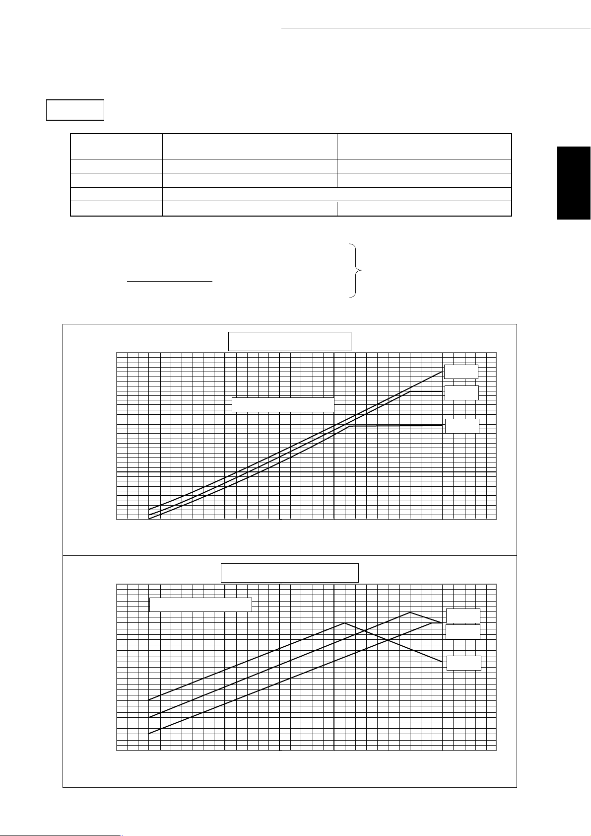
2-2. Correction by total indoor
PUMY-71VM
1) Capacity
10.0
9.0
8.0
7.0
Capacity(kW)
6.0
5.0
4.0
40 50 60 70 80 90 100
Heating
Cooling
Total capacity of indoor units
2) Input
4.00
3.50
3.00
Input(kW)
2.50
2.00
3) Current
20.0
18.0
16.0
Current(A)
14.0
Cooling
Heating
40 50 60 70 80 90 100
Total capacity of indoor units
Cooling
Heating
220V 60Hz
220V 50Hz
220V 50Hz
220V 60Hz
220V 50Hz
220V 60Hz
220V 50Hz
220V 60Hz
12.0
10.0
40 50 60 70 80 90 100
Total capacity of indoor units
Page 7

PUMY-125VM
7
PUMY
11
Outdoor units / Y series / PUMY-71·125VM
1) Capacity
17.0
15.0
13.0
11.0
Capacity(kW)
9.0
7.0
60 80 100 120 140 160 180
2) Input
7.00
6.00
5.00
Input(kW)
4.00
Total capacity of indoor units
Heating
Cooling
50Hz
60Hz
50Hz
60Hz
Cooling
Heating
3.00
2.00
3) Current
36.0
34.0
32.0
30.0
28.0
26.0
Current(A)
24.0
22.0
20.0
18.0
16.0
14.0
60 80 100 120 140 160 180
Total capacity of indoor units
220V 50Hz
Cooling
Heating
60 80 100 120 140 160 180
Total capacity of indoor units
220V 60Hz
220V 50Hz
220V 60Hz
Page 8

8
PUMY
2-3 Correction by refrigerant piping length
To obtain a decrease in cooling/heating capacity due to refrigerant piping extension, multiply by the capacity
correction factor based on the refrigerant piping equivalent length in the table below.
• Cooling capacity correction
PUMY-71VM
Cooling capacity
1.0
0.9
0.8
correction factor
0.7
1002030405060
• Heating capacity correction
PUMY-71VM
1.0
Total capacity of indoor unit
35
53
71
93
Piping equivalent length (m)
PUMY-125VM
1.0
0.9
0.8
Cooling capacity
correction factor
0.7
10520304050607075
PUMY-125VM
1.0
Total capacity of indoor unit
63
94
125
163
Piping equivalent length (m)
0.9
0.8
Heating capacity
correction factor
0.7
10020304050 60
Piping equivalent length (m)
0.9
0.8
Heating capacity
correction factor
0.7
10020304050 60
Piping equivalent length (m)
• How to obtain piping equivalent length
➀ PUMY-71VM
Equivalent length = (Actual piping length to the farthest indoor unit) + (0.3 ✕ number of bent on the piping)m
➁ PUMY-125VM
Equivalent length = (Actual piping length to the farthest indoor unit) + (0.35 ✕ number of bent on the piping)m
Page 9

9
PUMY
11
Outdoor units / Y series / PUMY-71·125VM
2-4 Correction at frosting and defrosting
When a decrease in heating capacity due to frosted and defrosting operations is considered, the value multiplied by the correction factor in the table below represents the heating capacity.
2-5 Operation limit
Correction factor table
Outdoor inlet air temp
(˚CWB)
6 4 2 0 -2 -4 -6 -8 -10
Correction factor
• Cooling
30
25
20
15
Indoor temperature (˚CWB)
10
-5 0 5 10 15 20 25 30 35 40 45 50
• Heating
30
25
1.0 0.98 0.89 0.88 0.89 0.9 0.95 0.95 0.95
Outdoor temperature (˚CDB)
20
15
Indoor temperature (˚CDB)
10
-15 -10 -5 0 5 10 15 20
Outdoor temperature (˚CDB)
Page 10

10
PUMY
3. Sound levels
PUMY-71VM
Measurement condition
70
1m
A
1m
Sound pressure level in anechoic room
57 dB (A)
60
NC60
50
B
40
30
20
Approximate minimum
OCTAVE BAND PRESSURE LEVEL< dB> 0dB = 0.0002µbar
audible limit on
continuous noise
NC50
NC40
NC30
NC20
10
63 125 250 500 1000 2000 4000 8000
OCTAVE BAND CENTER FREQUENCIES<Hz>
PUMY-125VM
Measurement condition
1m
A
1m
B
Sound pressure level in anechoic room
58 dB (A)
70
60
50
40
30
20
Approximate minimum
OCTAVE BAND PRESSURE LEVEL< dB> 0dB = 0.0002µbar
audible limit on
continuous noise
10
63 125 250 500 1000 2000 4000 8000
OCTAVE BAND CENTER FREQUENCIES<Hz>
NC60
NC50
NC40
NC30
NC20
Page 11

11
PUMY
11
Outdoor units / Y series / PUMY-71·125VM
4. External dimensions
PUMY-71VM
Terminal block for transmission
Terminal block for central remote control
Optional parts
(base branching
Terminal block for Power source
pipe) installation
hole
ø15.88(5/8F)
ø9.52(3/8F)
Gos refrigerant-pipe
connection
Liquid refrigerant-pipe
connection
Knock out hole for right piping
Unit : mm
Knock out holes fo power line 2-ø27
ø27
shaped notched holes
(standard bolt M10)
Air intake
Air intake
Air outlet
Optional parts
installation hole
Side air intake
Service panel
Handle for
moving
Rear air intake
Handing for moving
Knock out holes for
power line 2-
Knock out hole
for front piping
Piping cover
Oval holes
(standard bolt M10)
Bottom piping hole
Drain hole
(3-ø33 hole)
Handle for moving
Rear piping hole
when a piping cover is used for aesthetic reasons.
✻1...Indicates the dimensions of the cutoff valve connector.
✻2...Make sure that the panel can be easily removed for maintenance
Page 12

12
PUMY
PUMY-125VM
Optional parts
(base branching
pipe) installation
hole
Unit : mm
ø9.52 (3/8F)
Knock out holes for power line 2-ø 29
Air intake
Teminal block for transmission
Teminal block for central remote control
Terminal block for power source
Air outlet
Optional parts
installation hole
Handle for
moving
Liquid refrigerant pipe
connection
Gos refrigerant-pipe
connection ø19.05 (3/4F)
Knock out hole for right piping
Knock out holes for
power line 2-ø27
Knock out hole for
front piping
Piping cover
Oval holes
(standard bolt M10)
Bottom piping hole
shaped dotched holes
(standard bolt M10)
Drain hole
(3-ø33 hole)
Handle for moving
Side air intake
Rear air intake
Rear piping hole
when a piping cover is used for aesthetic reasons.
✻1...Indicates the dimensions of the cutoff valve connector.
✻2...Make sure that the panel can be easily removed for maintenance
Page 13

13
PUMY
11
Outdoor units / Y series / PUMY-71·125VM
5. Electrical Wiring Diagram
PUMY-71VM
SYMBOL
AC,CT
CH
CNA
CND
CNS1
CNS2
CN1
CN2
CN3
CN4
CN5
CN6
CN40
CN41
CN51
CN3D
CNCT
C1,2
C3
C5
DS
D1
DCL
POWER SUPPLY
Single-phase 220-240V 50Hz
Single-phase 208-230V 60Hz
Current detection
Crankcase heater
Connector <Power supply>
Connector <DC Power supply>
Connector <Multi system>
Connector <Centralized control>
Connector <Controller drive control>
Connector <Power sync signal, protection>
Connector <Power supply 30V, 12V, 5V>
Connector <Inverter signal 5V>
Connector <IPM power supply>
Connector <IPM power supply, trouble output>
Connector <Centralized control power supply>
Connector <For storing jumper connector>
Connector <Compressor drive signal output>
Connector <Demand signal, silent mode input>
Connector <Current detection>
Fan motor capacitor
Capacitor <Smoothing>
Capacitor <Power factor improvement>
Diode stack
Diode <Power factor improvement>
Reactor
TO INDOOR UNIT
CONNECTING WIRES
DC 30V (Non-polar)
FOR CENTRALIZED
CONTROL
DC 30V (Non-polar)
NAME NAME
M1
M2
S
M1
M2
S
L1
L2
TB3
BRN
BRN
TB7
ORN
ORN
TB1
RED
WHT
GRN/YLW
FUSE(30A)
SYMBOL SYMBOL
F.C
FUSE1
FUSE2
FUSE
IPM
LD1
Fan control
Fuse(2A)
Fuse(6A)
Fuse(30A)
Intelligent power module
Digital indication LED
<Operation inspection indication>
NF1
RED
1
2
MC
MF1,2
NF1
R1
R2
SLEV
SV1
SW1
SW2
SW3
SW4
SW5
SWU1
SWU2
SWU3
TB1
1
CNCT
Compressor
Fan motor (Inner thermostat)
Noise filter
Resistor <Rush current protect>
Resistor <Discharge>
Expansion valve
Solenoid valve <Hot gas bypass>
Switch <Display selection selfdiagnosis>
Switch <Function selection>
Switch <Test run>
Switch <Model selection>
Switch <Function selection>
Switch <Unit address selection,1st digit>
Switch <Unit address selection,2nd digit>
Switch <Unit address selection,3rd digit>
Terminal block <Power supply>
1234
CN41
CN51
CN40
(WHT)
(WHT)
CNS2
1
(YLW)
2
0
1
(3rd digit)
X1
CNA
31
WHT
WHT
CH
PUMY-71VM
Only
DS
9
8
7
6
SWU3
CH
WHT
4
5
CNS1
1
(RED)
2
<MULTI CONTROLLER BOARD>
<POWER SUPPLY BOARD>
FUSE2
(6A)
1
3
RED
RED
3
2
WHT
4
LD1
2
3
SWU2
(2nd digit)
1
3
BLK
RED
RED
WHT
(WHT)
0
1
9
9
2
8
8
3
7
7
4
6
6
5
SWU1
(1st digit)
X2
52C 21S4
31
BLK
RED
R1
RED
52C
ZNR
CN3D
(WHT)
0
1
2
4
5
X3
RED
C5
3
3
RED
SV152C 21S4
DCL
1
321543214321
SV1
2
CNCT
(WHT)
RED
MF1
C1
D1
3
WHT
RED
1
1
MF1
F.C
BLU
ORN
3
MF2
C2
RED
R2
THHS
THHS
(BLK)
OFF
ON
OFF
CN1
6
6
FUSE1
MF2
1
WHT
RED
TB3
TB7
THHS
TH1
TH2
TH5
TH6
X1
X2
X3
ZNR
21S4
26C
52C
63HS
TH6 TH5
TH6
(WHT)
ON
SW3
12 321
(RED)
3
21
3
CN1
(RED)
CND
BLU
ORN
RED
+
C3
Terminal block <Transmission>
NAME
Terminal block
<Transmission> (Centralized control)
Thermistor
<IPM Radiator panel temperatuer detection>
Thermistor <Discharge temperatuer detection>
Thermistor
<Low pressure saturated temperatuer detection>
Thermistor
<Pipe temperatuer detection, judging defrost>
Thermistor <Outdoor temperatuer detection>
Relay
<Crankcase heater, magnetic contactor>
Relay <4-way valve>
Relay <Solenoid valve>
Varistor
4-Way valve
Thermal switch <Compressor>
Magnetic contactor
<Inverter main circuit>
High pressure sensor
<Discharge pressure detection>
TH2 TH1
63HS
SLEV
6
3
2123
453
AC,CT
(YLW)
CN4
7
6
67
W
SLEV
(YLW)
5
4123
5
CN4
(YLW)
6
2
1
RED
1234
11231121321
TH1
TH5
(GRN)
(GRN)
SW1
ON
OFF
34567821
SW4
ON
OFF
4
(YLW)
CN2
43
21
5
6
645
26C
6
12
4321
5
CN2
(YLW)
(2A)
1
2
RED
WHT
(YLW)
3
WHT
(BLK)
(WHT)
CN5
1
P(+)
CN5
(WHT)
<GATE AMP BOARD>
N(-)
63HS
TH2
(WHT)
(WHT) (WHT)
SW2
12345678910
SW5
87654321
(WHT)
CN3
1263
7
YLW
YLW
21
3621
7
26C
CN3
(WHT)
(WHT)
CN6
10
321
9652
63 7
96521
10
321
CN6
(WHT)
V
U
WHT
P(+)
RED
U
W
V
BLU
WHT
AC.CT
V
W
MC
1.Refer to the wiring boards of the indoor units for details on wiring of each indoor unit.
N(-)
<IPM>
U
2.The transmission line is two-wire type and has no polarity.
3.Mark shows the terminal board,mark the connector .Symbols in parentheses () show the colors of connectors.
4.Self-diagnosis function
The indoor and outdoor units can be diagnosed automatically using the self-diagnosis switch(SW1) and LD1(LED indication)
found on the multi-controller of the outdoor unit.
LED indication : Set all contacts of SW1 to OFF.
Page 14

14
PUMY
PUMY-125VM
SYMBOL
AC,CT
AR
CB
CH
CNA
CND
CNS1
CNS2
CN1
CN2
CN3
CN4
CN5
CN6
CN40
CN41
CN51
CN3D
C1,2
C3,4
C5,6
C7
D
DB1,DB2
TO INDOOR UNIT
CONNECTING WIRES
DC 30V (Non-polar)
FOR CENTRALIZED
CONTROL
DC 30V (Non-polar)
POWER SUPPLY
Single-phase 220-240V 50Hz
Single-phase 208 -230 60Hz
Current detection
Surge absorber
Smoothing capacitor
Crankcase heater
Connector <Power supply>
Connector <DC Power supply
Connector <Multi system>
Connector <Centralized control>
Connector <Controller drive control>
Connector <Power sync signal, protection>
Connector <Power supply 30V, 12V, 5V>
Connector <Inverter signal 5V>
Connector <IPM Power supply>
Connector <IPM Power supply, trouble output>
Connector <Centralized control power supply>
Connector <For storing jumper connector>
Connector <Compressor drive signal output>
Connector <Demand signal, silent mode input>
Fan motor capacitor
Capacitor <Power factor improvement>
Capacitor
Capacitor <Filter>
Diode <Power factor improvement>
Diode stack
NAME NAME
SYMBOL
DCL
F.C
FUSE1
FUSE2
FUSE
IPM
LD1
Reactor
Fan control
Fuse(2A)
Fuse(6A)
Fuse(60A)
Intelligent power module
Digital indication LED
<Operatioin inspection indication>
Compressor
Fan motor (Inner thermostat)
Noise filter
Resistor <Discharge>
Resistor <Rush current protect>
Expansion valve
Solenoid valve <Hot gas bypass>
Switch <Display selection selfdiagnosis>
Switch <Function selection>
Switch <Test run>
Switch <Model selection>
Switch <Function selection>
Switch <Unit addres selection , 1st digit>
Switch <Unit address selection 2nd digit>
Switch <Unit address selection 3rd digit>
Terminal block <Power supply>
0
9
8
7
6
1
1
2
4
5
FUSE2
(6A)
3
RED
CN41
(WHT)
LD1
0
1
9
8
3
7
4
6
5
SWU2
(2nd digit)(3rd digit)
CNA
1
3
BLU
WHT
CH
PUMY-125VM
Only
YLW
4321
2
8
3
7
SWU1
(1st digit)
CH
WHT
CH
DB1 DB2
2
3
1
X4
8
CN40 CN51 CN3D
(WHT) (WHT)(WHT)
CNS2
1
(YLW)
2
CNS1
1
(RED)
2
SWU3
<MULTI CONTROLLER BOARD>
<POWER SUPPLY BOARD>
NF
RED
143
BLK
2
GRN/YLW
M1
M2
M1
M2
TB3
S
TB7
S
TB1
L
N
BRN
BRN
ORN
ORN
RED
RED
BLK
BLK
GRN
GRN/YLW
RED
C5
C6
MC
MF1,2
NF
RB
RS
SLEV
SV1
SW1
SW2
SW3
SW4
SW5
SWU1
SWU2
SWU3
TB1
AR
RED
FUSE(60A)
321543214321
0
1
9
2
3
4
6
5
X2X1X3
21S4
52C
1
3
1
3
YLW
YLW
RED
RED
21S4
52C SV1
BLK
RED
2
ZNR
3
52C
1
BLK
X4
RS
BRN
BRN
3
YLW
7
3
RED
RED
C3
1
DCL
C4
5
SV1
RED
WHT
BLU
3
MF1
C1
BLK
BLK
BRN
1
WHT
RED
1
3
RB
F.C
MF1
BLU
ORN
D
BLU
SYMBOL
TB3
TB7
THHS
TH1
TH2
TH5
TH6
X1
X2
X3
X4
ZNR
21S4
26C
52C
63HS
THHS
CN1
3
6
3
6
CN1
(RED)
MF2
1
3
BLU
WHT
MF2
RED
ORN
C2
2
RED
RED
+
2
6
-
BLK
Terminal block <Transmission>
NAME
Terminal block
<Transmission> (Centralized control)
Thermistor
<IPM radiator panel temperature detection>
Thermistor <Discharge temperature detection>
Thermistor
<Low pressure saturated temperature detection>
Thermistor
<Pipe temperature detection, judging defrost>
Thermistor
<Outdoor temperature detection>
Relay
<Crankcase heater, magnetic contactor>
Relay<4-way valve>
Relay<Solenoid valve>
Relay
Varistor
4-way valve
Thermal switch <Compressor>
Magnetic contactor
<Inverter main circuit>
High pressure sensor
<Discharge pressure detection>
TH1
TH2TH5TH6
63HS
SLEV
3
6
THHS
(RED)
2
2132311
TH6
TH5
(WHT)
(GRN)
(BLK)
SW1
ON
OFF
12 876543
SW3
SW4
ON
OFF
12 4321 12345678
(YLW)
CN2
1
3
2
4
6
1
5
26C
1
2
(YLW)
CND
1
RED
CB
4
5
6
(YLW)
CN2
FUSE1
(2A)
CN5
2
3
BLK
RED
P(+)
C7
BLK
N(-)
<IPM>
1
3
2
2
5
1
2
1
CN5 CN6
(WHT) (WHT)
3121
TH2
TH1
(WHT)(GRN)
ON
OFF
SW5
ON
OFF
CN3
7
YLW
YLW
21
7
CN3
26C
(BLK)
(WHT)
CN6
10
9
6
1
6
1
965
10
<GATE AMP BOARD>
WVX4U
BLU
RED
WHT
V
U
W
MC
63HS
SW2
(WHT)
3
6
(WHT)
(WHT)
2
2
AC.CT
(WHT)
263
546
2
3
3
3
456
123
321
SLEV
(WHT)
10987654321
1
1
CN4
657
AC.CT
(YLW)
(YLW)
213
4
2
1
7
54362
1
7
CN4
(YLW)
RED
WHT
1.Refer to the wiring boards of the indoor units for details on wiring of each indoor unit.
2.The transmission line is two-wire type and has no polarity.
3.Mark shows the terminal board,mark the connector.Symbols in parentheses() show the colors of connectors.
4.Self-diagnosis function
The indoor and outdoor units can be diagnosed automatically using the self-diagnosis switch(SW1) and LD1(LED indication)
found on the multi-controller of the outdoor unit.
LED indication:Set all contacts of SW1 to OFF.
Page 15

15
PUMY
11
Outdoor units / Y series / PUMY-71·125VM
6. Refrigerant circuit diagram and Thermal sensor
PUMY-71, 125VM
Thermistor TH6
(outdoor air
temperature sensor)
Cooling
Heating
(Refrigerant flow)
High-pressure sensor
discharge pressure sensor
(63HS)
4-way
valve
Strainer
Service port
Strainer
Oil
separator
Flare
Thermistor
Check valve
(High prssure)
Check valve
(low pressure)
Capillary
Thermistor TH5
(pipng temperature
monitoring and
determination)
Electromag-
netic valve
(SV1)
TH1 (discharge
temperature
sensor)
Capillary
tube 1
Strainer
tube 3
Outdoor heat exchanger
Thermistor THHS
(Radiator panel
temperature sensor)
Compressor
(MC)
Strainer
Accumulator
Electronic expansion valve (SLEV)
Capillary
tube 2
Flare
Overcooling heat exchanger
Strainer
Strainer
Service port
Connector
Gas pipe
Flare
Thermistor TH23
for monitoring gas
pipe temperature
Indoor heat
exchanger
Thermistor
TH21 (intake
temperature
detection)
Thermistor TH2
(Saturation temperature
of suction pressure)
Thermistor
TH22 (piping
temperature
detection)
Connector
Liquid pipe
Indoor unit Outdoor unit
Flare
Linear expansion
valve (LEV)
Page 16

16
PUMY
 Loading...