

Page 1

HOME-CINEMA TELEVISION
MODELS
738 Series
838 Series
BASIC OWNER’S GUIDE
This manual provides basic connection, setup, and operating instructions. Please visit our website at
www.Mitsubishi-tv.com to view or download a detailed owner’s guide that fully describes the features
of this TV. Follow the Support link to the Product Documents page.
For questions:•
Visit our website at www.mitsubishi-tv.com. E-mail us at MDEAservice@mdea.com. Call Consumer Relations at - 800-332-2119 for operational or connection assistance.
For information on • System Reset, please see the back cover.
To order replacement or additional remote controls, visit our website at www.mitsuparts.com or call •
800-553-7278.
838 Series.• IR emitter cables for NetCommand home-theater control are available for purchase from
Mitsubishi.
number 299P254020 (four-ended cable).
Call 800-553-7278 and
request either part number 242D483020 (two-ended cable) or part
®
Page 2
CAUTION
RISK OF ELECTRIC SHOCK
DO NOT OPEN
CAUTION: TO REDUCE THE RISK OF ELECTRIC
SHOCK, DO NOT REMOVE COVER (OR BACK).
NO USER SERVICEABLE PARTS INSIDE. REFER
SERVICING TO QUALIFIED SERVICE PERSONNEL.
The lightning flash with arrowhead symbol
within an equilateral triangle is intended to
alert the user of the presence of uninsulated
“dangerous voltage” within the product’s
enclosure that may be of sufficient magnitude to constitute a risk of electric shock to persons.
The exclamation point within an equilat-
eral triangle is intended to alert the user to
the presence of important operating and
maintenance (servicing) instructions in the
literature accompanying the product.
MAINS DISCONNECTION: The mains plug is used
as the disconnect device. The mains plug shall remain
readily operable.
St and Requirement
CAUTION: Use these Mitsubishi TV models only with
the Mitsubishi stand models shown here. Other stands
can result in instability and possibly cause injury.
TV Model Stand Model
WD-60738, WD-65738
WD-65838
WD-73738
WD-73838
82-inch TVs. Mitsubishi does not design, manufacture, or sell matching bases for 82-inch televisions
(WD-82738, WD-82838). When selecting a stand, base,
or other furniture to support the TV, please make sure it
is designed with the appropriate dimensions for stability and to support the TV’s total weight as well as the
weight of any additional equipment you plan to store.
TV WEIGHT: This TV is heavy. Exercise extreme care
when lifting or moving it. Lift or move the TV with a
minimum of two adults. To prevent damage to the TV,
avoid jarring or moving it while it is turned on. Always
power off your TV, unplug the power cord, and disconnect all cables before moving it.
MB-S60/65A
MB-S73A
FCC Declaration of Conformity
Product: Projection Television Receiver
Models: WD-60738, WD-65738, WD-73738,
WD-82738
WD-65838, WD-73838, WD-82838
Responsible
Party:
Telephone: (800) 332-2119
This device complies with Part 15 of the FCC Rules.
Operation is subject to the following two conditions:
(1)
This device may not cause harmful interference,
and
(2) This device must accept any interference
received, including interference that may cause
undesired operation.
Note: This equipment has been tested and found
to comply with the limits for a Class B digital device,
pursuant to part 15 of the FCC Rules. These limits
are designed to provide reasonable protection
against harmful interference in a residential installation. This equipment generates, uses and can
radiate radio frequency energy and, if not installed
and used in accordance with the instructions, may
cause harmful interference to radio communications. However, there is no guarantee that interference will not occur in a particular installation. If this
equipment does cause harmful interference to radio
or television reception, which can be determined
by turning the equipment off and on, the user is
encouraged to try to correct the interference by one
or more of the following measures:
Reorient or relocate the receiving antenna. -
Increase the separation between the equip- ment and the receiver.
Connect the equipment into an outlet on a circuit different from that to which the
receiver is connected.
Consult the dealer or an experienced radio/ -
TV technician for help.
Changes or modifications not expressly
approved by Mitsubishi could cause harmful
interference and would void the user’s authority
to operate this equipment.
Mitsubishi Digital Electronics
America, Inc.
9351 Jeronimo Road
Irvine, CA 92618-1904
WARNING: To reduce the risk of fire or electric shock,
do not expose this apparatus to rain or moisture.
This apparatus shall not be exposed to dripping or
splashing and no objects filled with liquids, such as
vases, shall be placed on the apparatus.
For assistance call 1(800) 332-2119
WARNING: This product contains chemicals known
to the State of California to cause cancer and/or birth
defects or other reproductive harm.
Note: Features and specifications described in this
owner’s guide are subject to change without notice.
Page 3
Contents
1 Basic Setup and Operation
Remote Control
The STATUS Indicator ..................... 7
Setting Up and Using TV Inputs
Basic TV Operation....................... 9
2 TV Connections
Main Connection Panel
838 Series Side Inputs ................... 10
Connection Types and Audio/Video Quality .... 10
H
DMI Device .............................11
DVI Video Device ....................... 11
Y Pb Pr Component Video Device ........... 11
Composite Video Device .................. 11
Antenna or Cable TV Service ............... 12
VCR or DVD Recorder to an Antenna or
Wall Outlet Cable
A/V Receiver .......................... 13
A/V Receiver with HDMI Output ............. 13
......................... 6
.............. 7
................... 10
...................... 12
For Your Records
Record the model number, serial number, and
purchase date of your TV. The model and serial
numbers are on the back of the TV. Refer to this
page when requesting assistance with the TV.
MODEL NUMBER
SERIAL NUMBER
PURCHASE DATE
RETAILER NAME
LOCATION
Custom cabinet installation must allow for proper
air circulation around the television.
NOTE TO CATV SYSTEM INSTALLER: THIS REMINDER
IS PROVIDED TO CALL THE CATV SYSTEM INSTALLER’S
ATTENTION TO ARTICLE 820-40 OF THE NEC THAT PROVIDES GUIDELINES FOR THE PROPER GROUNDING AND,
IN PARTICULAR, SPECIFIES THAT THE CABLE GROUND
SHALL BE CONNECTED TO THE GROUNDING SYSTEM OF
THE BUILDING, AS CLOSE TO THE POINT OF CABLE ENTRY
AS PRACTICAL.
3 TV Features
FAV (Favorites)
ChannelView Channel Listings
......................... 14
.............. 15
Photos and Moving Video as Composite Video .. 15
3D Video ............................. 16
Sound Projector ........................ 18
StreamTV™ Internet Media ................ 19
Wireless Audio Playback
.................. 20
4 TV Menus
Picture
............................... 21
Sound ............................... 22
Captions ............................. 23
Setup ............................... 24
Inputs
............................... 25
Lock ................................ 26
Appendices
Appendix A: TV Care
Lamp-Cartridge Replacement and Cleaning
. 27
Cleaning Recommendations ............ 29
Appendix B: Programming the Remote Control . 30
Appendix C: Troubleshooting
.............. 31
Mitsubishi TV Software .................... 34
Warranty
.............................. 38
Network Service Disclaimer ................ 39
Internal Fans
Internal cooling fans maintain proper operating temperatures inside the TV. It is normal to hear the fans
when you first turn on the TV, during quiet scenes
while viewing the TV, and for a short time after shutting
off the TV. You may notice louder fan noise about 30
seconds after shutting off the TV and while using the
Bright Lamp Energy setting.
Lamp Replacement
For lamp-replacement instructions, see Appendix A .
To Order a Replacement Lamp Under Warranty
Call (800) 553-7278. Please have model number, serial
number, and TV purchase date available.
Important: All lamps replaced under warranty
must be returned to Mitsubishi where they will be
inspected to verify failure defects.
To Purchase a Replacement Lamp After Warranty
Visit our website at www.mitsuparts.com or call (800)
553-7278. Order new lamp part number 915B441001.
TV Software
Do not attempt to update the software of this TV with
software or USB drives not provided by or authorized
by Mitsubishi Digital Electronics America, Inc. Nonauthorized software may damage the TV and will not be
covered by the warranty.
Children and TV Viewing
The American Academy of Pediatrics discourages
television viewing for children younger than two years of
age.
For assistance call 1(800) 332-2119
Page 4
4
Important Safety Instructions
Please read the following safeguards for your TV and
retain for future reference. Always follow all warnings
and instructions marked on the television.
1) Read these instructions.
2) Keep these instructions.
3) Heed all warnings.
4) Follow all instructions.
5) Do not use this apparatus near water.
6) Clean only with dry cloth.
7) Do not block any ventilation openings. Install in
accordance with the manufacturer’s instructions.
8) Do not install near any heat sources such as
radiators, heat registers, stoves, or other apparatus
(including amplifiers) that produce heat.
9) Do not defeat the safety purpose of the polarized
or grounding-type plug. A polarized plug has two
blades with one wider than the other. A grounding
type plug has two blades and a third grounding
prong. The wide blade or the third prong are
provided for your safety. If the provided plug does
not fit into your outlet, consult an electrician for
replacement of the obsolete outlet.
10) Protect the power cord from being walked on
or pinched particularly at plugs, convenience
receptacles, and the point where they exit from the
apparatus.
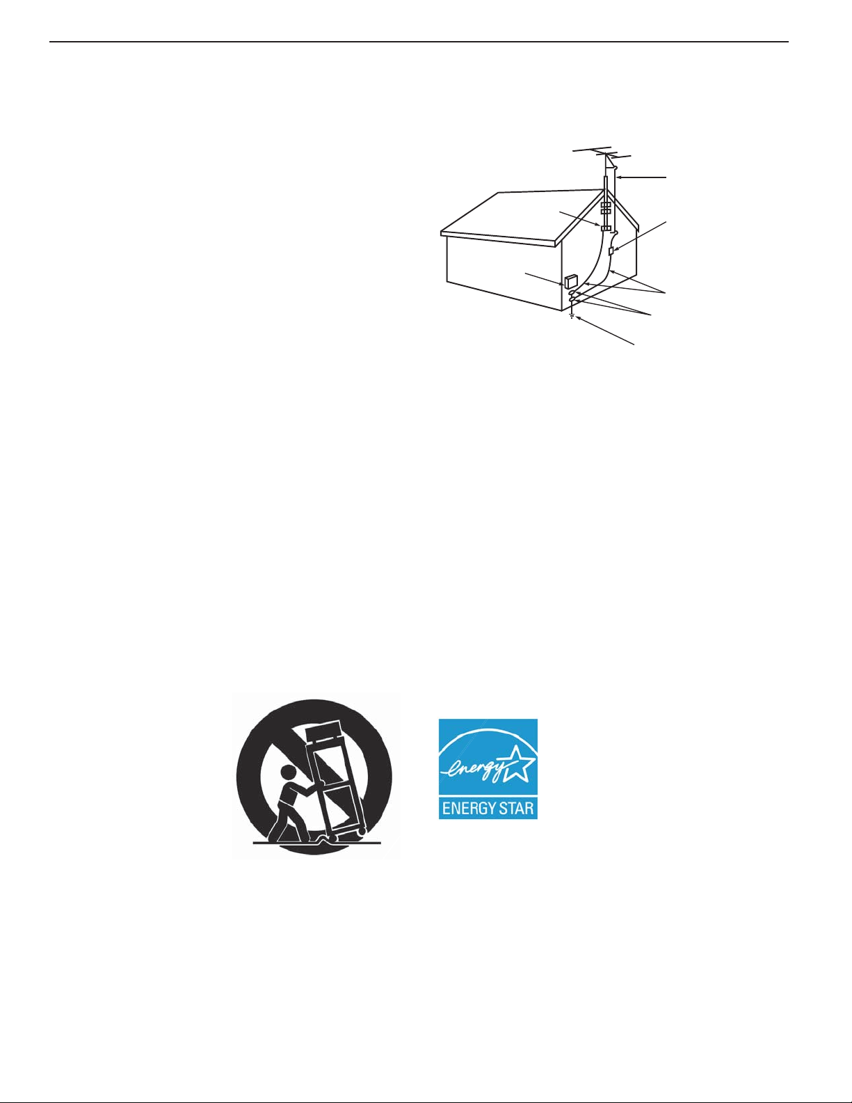
EXAMPLE OF ANTENNA GROUNDING
ANTE NNA
LEAD IN WIRE
GROUND CLAMP
ELECTRIC
SERVICE
EQUIPMENT
NEC — NATIONAL ELECTRICAL CODE
ANTE NNA
DISCHAR GE UNIT
(NE C AR TIC LE 810-20)
GROUNDING
CONDUCTORS
(NEC ARTICLE 810-21)
GROUND CLAMPS
POWER SERVICE GROUNDING
ELECTRODE SYSTEM
(NE C AR T 250, P AR T H)
Outdoor Antenna Grounding
If an outside antenna or cable system is connected
to the TV, be sure the antenna or cable system is
grounded so as to provide some protection against
voltage surges and built-up static charges.
Replacement Parts
When replacement parts are required, be sure the
service technician has used replacement parts specified by the manufacturer or have the same characteristics as the original part. Unauthorized substitutions
may result in fire, electric shock or other hazards.
11) Only use attachments/accessories specified by the
manufacturer.
12) Use only with the cart,
stand, tripod, bracket,
or table specified
by the manufacturer,
or sold with the
apparatus. When
a cart is used, use
caution when moving
the cart/apparatus
combination to avoid
injury from tip-over.
13) Unplug this apparatus
during lightning storms or when unused for long
periods of time.
14) Refer all servicing to qualified service personnel.
Servicing is required when the apparatus has been
damaged in any way, such as power-supply cord or
plug is damaged, liquid has been spilled or objects
have fallen into the apparatus, the apparatus has
been exposed to rain or moisture, does not operate
normally, or has been dropped.
The following TV models are
ENERGY STAR® qualified:
WD-65738, WD-73738, WD-82738
WD-65838, WD-73838, WD-82838
Products that earn the ENERGY
STAR prevent greenhouse gas
emissions by meeting strict energy
efficiency guidelines set by the U.S.
Environmental Protection Agency
and the U.S. Department of Energy.
For assistance call 1(800) 332-2119
Page 5
Basic Setup and Operation
1
Package Contents
Please take a moment to review the following list of
items to ensure that you have received everything.
Remote Control
Two AA Batteries
Basic Owner’s Guide
AA
AA
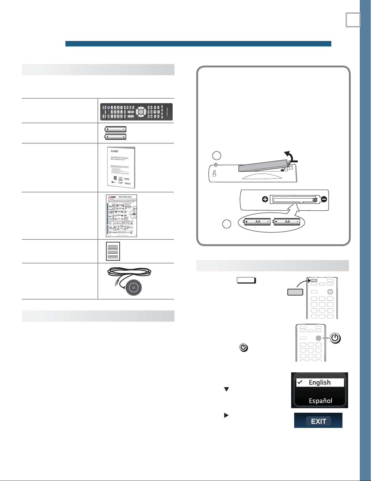
Installing the R emote Control
Batteries
Remove the remote control’s back cover by
1.
gently pressing in the tab and lifting off the cover.
Load the batteries, making sure the polarities
2.
(+) and (-) are correct. For best results, insert
the negative (-) end first.
Snap the cover back in place.
3.
1
The remote
control requires
two AA
batteries.
5
HDTV Quick Setup
Guide
Product Registration
Card
838 Series. Calibration
Microphone
Before You Begin
Review the important safety, installation, and oper-
1.
ating information at the beginning of this book.
Choose a location for your TV.
2.
• Allow at least four inches of space on all sides
of the TV to help prevent overheating. Overheating may cause premature failure of the TV
as well as shortened lamp life.
• Avoid locations where light may reflect off the
screen.
• See the stand requirements on page 2 .
2
First-Time Power-On
Press the
1.
ensure that the remote
control is in TV mode.
Aim the emitter (bulb)
2.
end of the remote control
at the TV and press the
POWER
Welcome screen.
If you wish to change the
3.
menu language to Español,
press
TV
key to
key . Wait for the
.
TV
TV
Install the batteries in the remote control.
3.
Plug the TV into an AC power outlet.
4.
4.
Press
Press
menu.
to highlight EXIT.
ENTER
to clear the
For assistance call 1(800) 332-2119
Page 6
6 1. Basic Setup and Operation
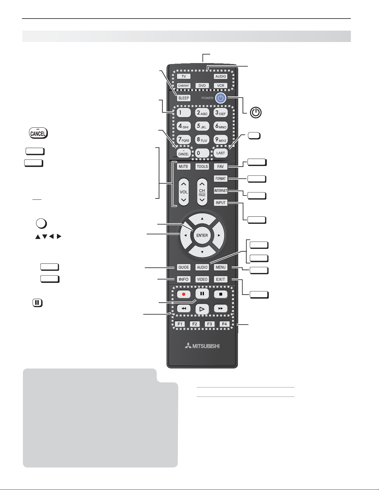
Re mote Control
Emitter End
MUTE
TOOLS
VOL
CH
PAGE
Sleep Timer
Number/letter keys
Channel tuning, page 8
Pass code entry, page 26
Adds a separator in digital channel
numbers. Clears some menu entries.
Mutes the TV speakers.
Displays shortcuts for the number keys.
Press to check if shortcuts are available
for the current device.
Controls volume of TV speakers.
Changes channels; moves to another
page in a menu or list.
ENTER
Selects a channel number or menu item.
Navigation and adjustment
controls
TV CAB/SAT DVD AUDIO VCR
P
ress the key for the device type to
control. Leave in TV mode for normal
TV viewing.
Powers TV on or off.
Returns to the previous channel.
LAST
FAV
FORMAT
INTERNET
INPUT
AUDIO
Displays up to nine favorite
sources. See page 14 .
Changes picture shape,
page 14
Connects to internet content
provided by VUDU™. See
page 19 .
Press to select a TV input.
See page 8 .
Audio adjustments, page 22
GUIDE
INFO
Record/Playback controls for external
devices. Additional setup is required.
The TV’s remote control can operate other
audio/video devices using any of these
methods:
• Program the remote control for the device ( page
30 ).
• Set up HDMI Control for HDMI devices compat-
ible with the TV.
• 838 Series. Perform Net Command setup for
device keys.
See the detailed owner’s guide at
www.mitsubishi-tv.com for information.
ChannelView listings, page 15
TV status or TV help.
(
PAUSE
)
Freezes a broadcast TV picture.
.
VIDEO
MENU
EXIT
838 Series. Special keys for use
with NetCommand IR control.
See the detailed owner’s guide at
www.mitsubishi-tv.com.
If You Turn Off the TV by Mistake
Press •
POWER
again, within about 60 seconds, to
have the TV come back on immediately.
If the •
STATUS
indicator is green and blinking rapidly,
(about 60 seconds after you shut off power), wait a
few moments for the indicator to stop blinking and
press
POWER
to turn the TV on again.
Video adjustments, page 21
Displays or clears the TV main
menu ( page 21 ).
back one menu.
Clears all menus.
Also steps
For assistance call 1(800) 332-2119
Page 7
1. Basic Setup and Operation 7
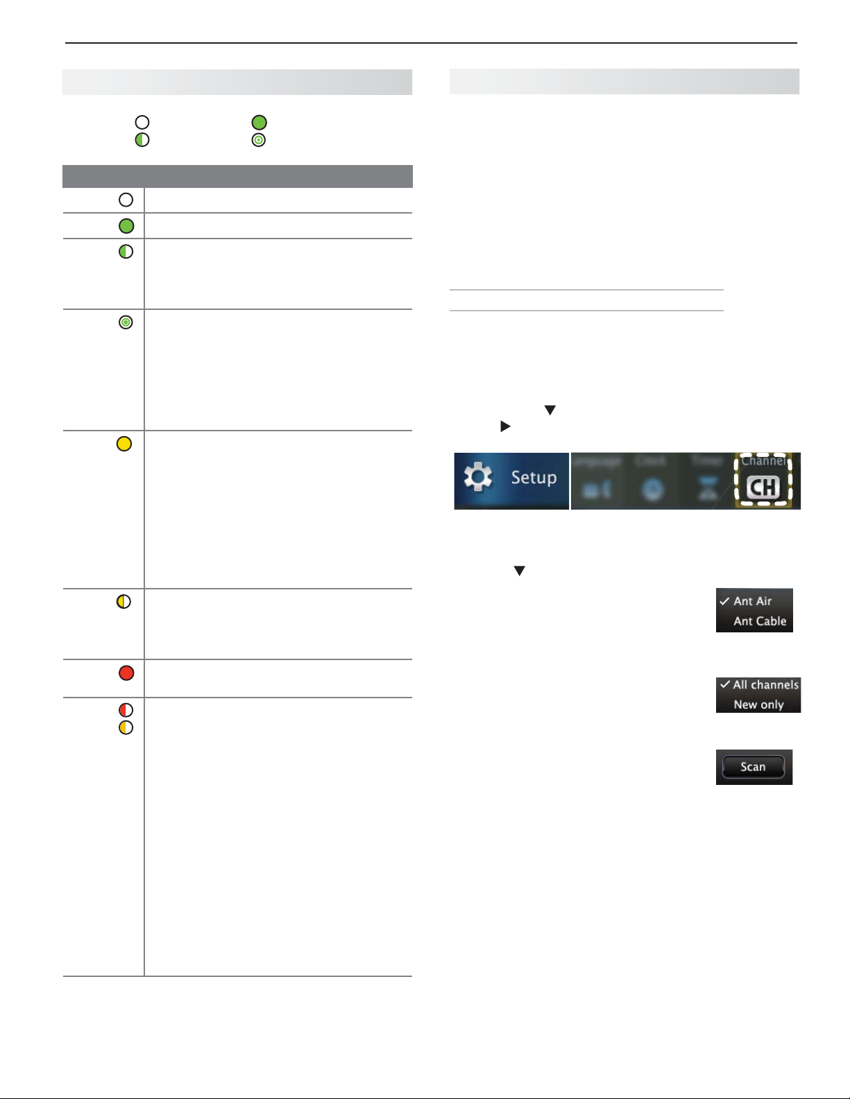
The STATUS Indicator
Key Off Steady On
LED Color TV Condition
None
Green
Green
Green
Yell ow
Yell ow
Red
Red/
Yell ow
Slow Blinking Fast Blinking
TV is powered off. Normal operation.
TV is powered on. Normal operation.
TV powered off, auto-on TV Timer is
set.
Normal operation. TV can be turned on
at any time.
TV just powered off and lamp is
cooling.
Sixty seconds after turning off TV, LED
will start to blink. TV can be turned back
on before blinking starts or after blinking stops, but not while the indicator is
blinking. Normal operation.
TV is too hot.
warning message and shut off if it overheats.
• Ambient room temperature may be
too high. Turn off the TV and let the
room temperature drop.
• Clear blocked air vents. Ensure at
least a four-inch clearance on all
sides of the TV.
Lamp access door is not secure or no
lamp installed.
TV will not operate until lamp access
door is secured. See Appendix A .
Lamp failure. Replace the lamp. See
Appendix A .
TV may require service.
Hold power button on front panel for •
10 seconds to reset TV.
If LED continues to flash red and •
yellow after reset, turn off the TV and
unplug it from the AC power source.
Wait one minute and then plug the
set back in.
If LED continues to flash red and •
yellow,
or call 1-800-332-2119 to receive
Authorized Service Center information.
You may be asked to count how
many times the LED flashes each
color to aid in troubleshooting.
The TV will display a
go to www.mitsubishi-tv.com
Settin g Up and Using TV Inputs
Using the ANT (Antenna) Input
If using an antenna or direct cable service (no cable
box), connect the incoming coaxial cable to the TV’s
ANT
input. Refer to page 12 .
You must perform a channel scan to enable reception of digital channels. If you skip this step, the TV
will receive only analog channels. The channel scan
will search for high-definition and standard-definition
channels available in the local area.
M emorizing Channels with Channel Scan
For the ANT input
To start channel memorization
Power on the TV.
1.
Press
2.
Start channel memorization from the Setup > Channel
menu.
3.
4.
5.
6.
To stop channel memorization before completion,
press
MENU
and open the Setup > Channel menu.
First press
use to highlight the Channel icon.
Press
Highlight
over-the-air antenna. Highlight Ant
Cable for service over direct cable
(no cable box). Press
check.
For first-time setup, highlight
channels. To scan for channels not
already in memory, highlight New
only. Press
Highlight
Channel memorization may take up
to 15 minutes to complete.
CANCEL
to navigate to the Setup icon, then
to enter the menu.
Ant Air if connected to an
ENTER
to add a
All
ENTER
to add a check.
Scan and press
.
ENTER
.
For assistance call 1(800) 332-2119
Page 8
8 1. Basic Setup and Operation
Setting Up and Using TV Inputs, continued
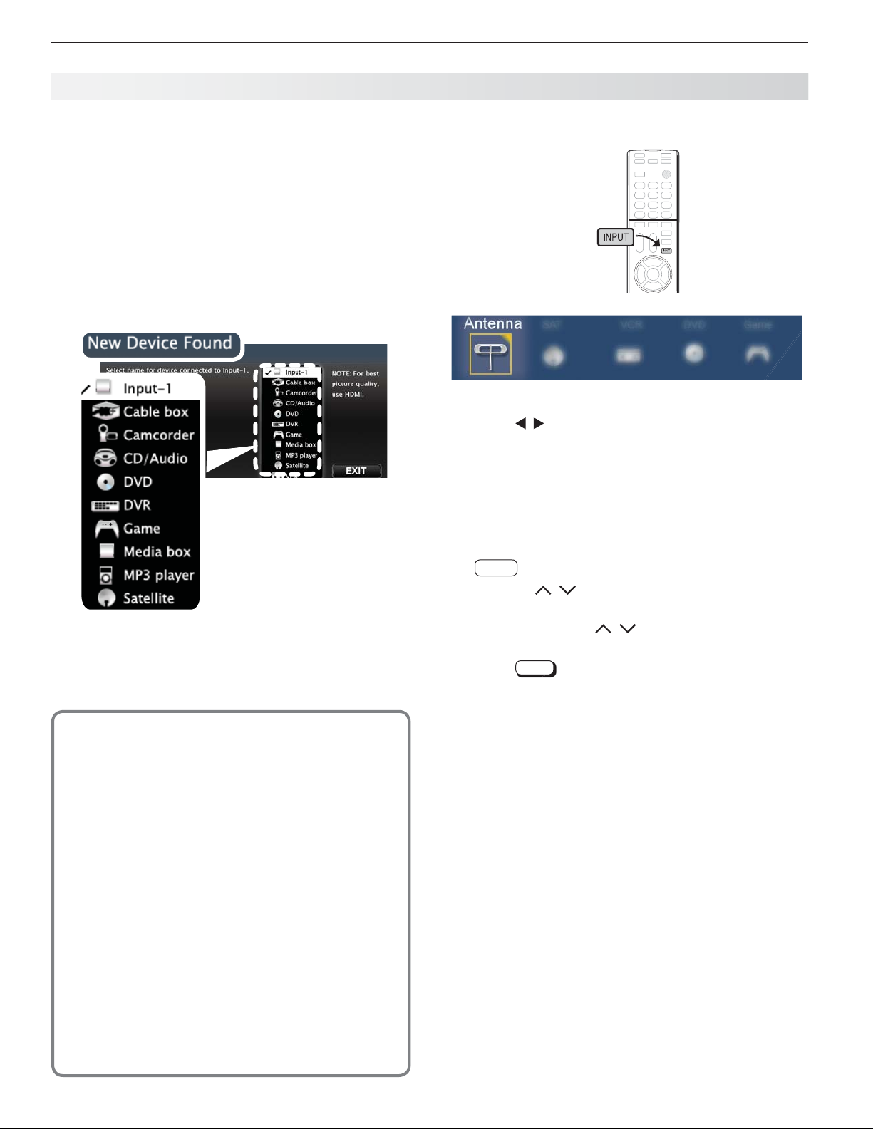
Setting Up Other Inputs
Power on the TV.
1.
Power on the devices to ensure detection.
2.
Connect one device to the TV, making note of the
3.
TV input jack.
The TV will display the New Device Found screen if
the connection type is detectable.
Highlight the device type in the on-screen list and
4.
press
ENTER
. The name you select here will appear
in the Input Selection menu.
Sample New Device
Found screen.
Press
5.
6.
EXIT
to close the New Device Found screen.
Repeat steps 3 through 5 for each additional device
you want to add.
About Auto Input S ensing
This TV’s Easy Connect™ Auto Input Sensing
feature detects most input connections automatically. Some exceptions are:
A connection on the •
TV audio outputs (analog and digital)•
An HDMI-equipped device that is powered off. •
Power on the device first to ensure detection.
Ethernet•
ANT
input
Selectin g an Input to Watch
Press
1.
Sample Input Selection menu, antenna input selected
Press
2.
Press
3.
INPUT
.
to highlight an input icon.
ENTER
to switch to the input.
Tun ing to Channels on the Antenna Input
Enter the channel number using the number keys •
on the remote control and press
For a two-part digital channel, such as 3-1, press •
—
.
CANCEL
Press •
CH
/ to change channels one channel at
a time.
Press and hold •
nels.
Press •
Use the Fav (Favorites) feature to tune to up to nine •
favorite channels. See page 14 .
Press • GUIDE to display ChannelView channel listings,
highlight a channel number, and press ENTER to tune.
LAST
CH
/ to speed through chan-
to return to the previous channel.
ENTER
.
3
Auto Input Sensing for Most Devices
When you first connect a device, the TV will:
a. Detect the connected device and auto-
matically switch to it.
b. Prompt you to identify the device type.
c. Repeat these steps for other newly
detected devices.
For assistance call 1(800) 332-2119
Page 9
1. Basic Setup and Operation 9
Basic TV Operation
Picture Settings
To get the best picture under different viewing con-
1.
ditions, set the Picture Mode first before changing
other video settings. See page 21 for a description
of the options.
a. Press
b. Press until the Picture Mode
c. Press to make one of these selections:
Press
2.
Press
3.
Wait a few seconds and
4.
Additional picture options are available through the following menus:
Menu Page
Picture > Picture Plus
Picture > Perfect (838 series) 22
Picture > 3D Mode 16
VIDEO.
option displays.
Name When to Use
Brilliant
Game
Bright For most daytime viewing
Natural For most nighttime viewing
to display the name of another adjustment.
to make the adjustment.
Under bright light
With gaming consoles (inputs
named
Game
or PC only)
the display will clear.
21
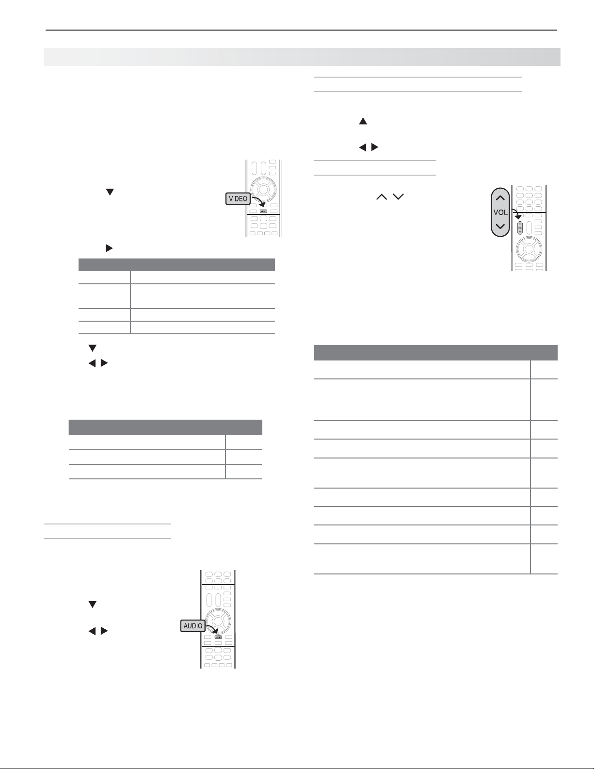
Changing Audio Settings (TV Speakers Only)
Press
1.
2.
3.
Controlling Sound Volume
AUDIO
.
Press
want. See page 22 for descriptions.
Press
Press •
sound level of the TV speakers.
See the full owner’s guide at •
www.mitsubishi-tv.com for
methods of controlling A/V receiver
volume.
to display the name of the adjustment you
to change.
VOL
/ to adjust the
More TV Features
Features covered in this Basic Owner’s Guide include:
Feature
Parental controls (Lock menu) 26
TV Clock. Set the TV Clock if you plan to use
the TV Timer ( page 24 ) or ChannelView ( page
15 ).
Favorite sources 14
ChannelView and custom channel collections 15
Changing the input names that appear in the
Input Selection menu (Inputs > Name menu)
Page
24
25
Audio Controls
Changing the Audio Output
To switch from the internal TV speakers to an external
sound system:
Press
1.
2.
3.
AUDIO
.
Press
TV Speakers option.
Press
to display the
to change.
3D Video 16
Internet video streaming with VUDU 19
Digital camera images as composite video 15
838 Series. Listening to a wireless audio
device with the TV speakers
See the detailed Owner’s Guide at
www.mitsubishi-tv.com for more on the features
described here and to learn about other features,
including:
HDMI control (CEC) of other A/V devices•
838 Series.• NetCommand IR control of other A/V
devices. Use of NetCommand requires purchase of
IR emitter cables available from Mitsubishi.
838 Series.• Center and rear channel audio output
838 Series.• Using an external subwoofer.
838 Series.• Viewing photo files from a USB device.
For assistance call 1(800) 332-2119
20
Page 10
10
1
2
3
HDMI
AUDIO
OUTPUT
Pb Pr
INPUT 2
INPUT 1
DIGITAL
AUDIO
OUTPUT
DVI/PC
(480i / 480p / 720p / 1080i)
LR INPUT
AUDIO
Y/ VIDEO
Pb Pr
Y/ VIDEO
3D
GLASSES
EMITTER
ANT
AUDIO
LR
LR
IR-NetCommand
Output/EXTERNAL
CONTROLLER INPUT
CENTER
INPUT
SUB
WOOFER
OUTPUT
LAN
AUDIO/SURROUND
OUTPUT
LR
USB HDMI 4
INPUT 3
AUDIO
LR
Pb
Y/ VIDEO
Pr
TV C onnections
2
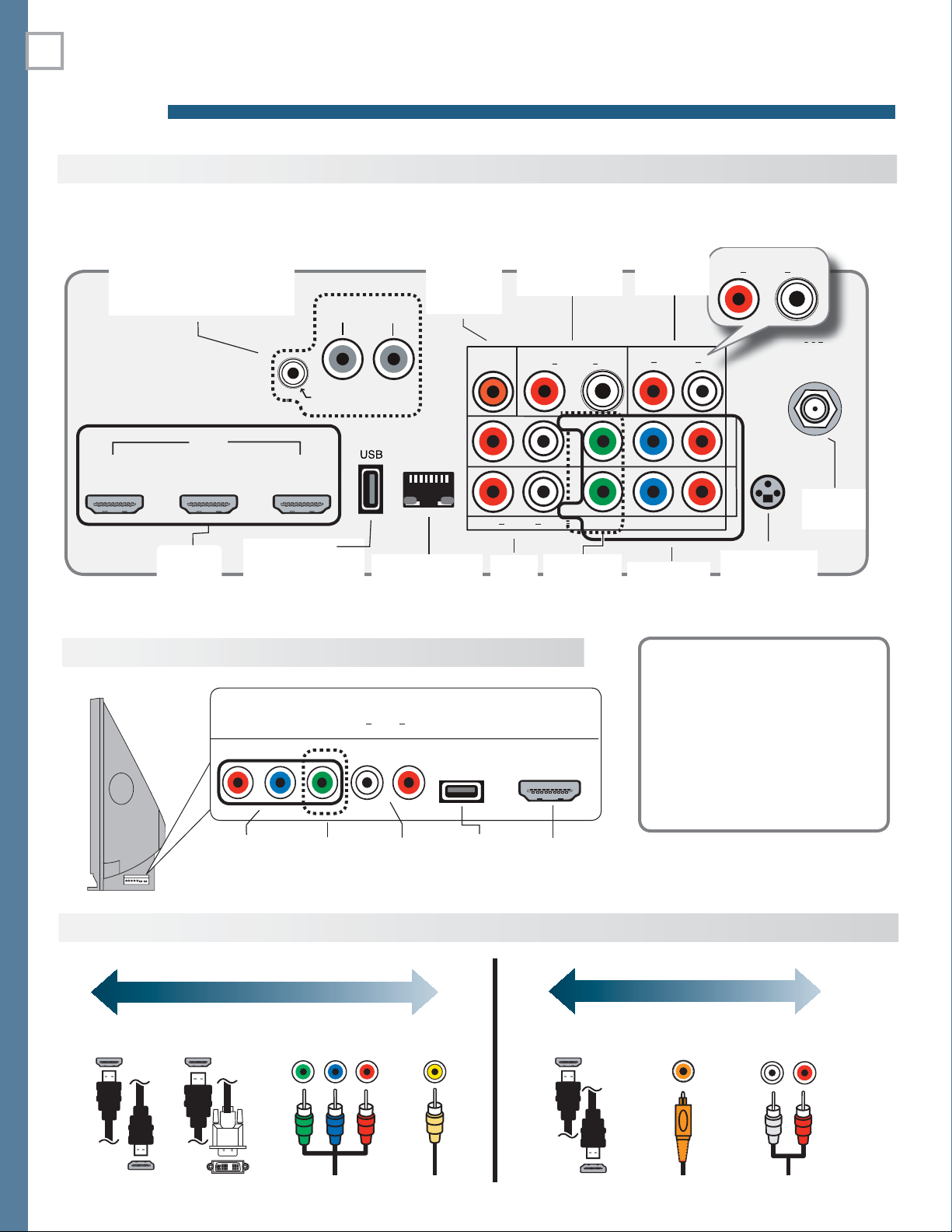
Main Connection Panel
838 Series Jacks. See
the full owner’s guide at
www.mitsubishi-tv.com.
DIGITAL
AUDIO
OUTPUT
( page 13 )
DVI/PC AUDIO
INPUT
page 11
AUDIO/SURROUND
OUTPUT
(838 series, page 23)
AUDIO
OUTPUT
( page 13 )
ANT
page 12
838 Series Side Inputs
Connection Types and Audio/Video Quality
HDMI
page 11
USB
(Accessory power
on all models;
(Ethernet, port
738 Series, wireless
adapter, page 19 )
Y Pb Pr
(component
video)
VIDEO QUALITY
VIDEO
(
composite
video)
Analog
GOODBEST
Component
HDMI-to-DVIHDMI Video Video
LAN
page 19 )
R & L
Audio
Input
Composite
(
page 19
USB
R & L
Analog
(composite
Audio
Input
HDMI
)
HDMI
VIDEO
video)
Y Pb Pr
(component
video)
3D GLASSES
EMITTER
( page 16 )
Auto Input Sensing
The TV’s Auto Input Sensing
feature automatically recognizes many connections and
prompts you to identify the
type of device connected.
See page 8 for more on Auto
Input Sensing.
AUDIO QUALITY
GOODBEST
Digital
L/R Analog
AudioAudio
For assistance call 1(800) 332-2119
Page 11
2. TV Connections 11
O
O
T
b
1
L
A
O
T
D
)
UT
A
O
Y/ VIDE
O
bDEO
3D
G
S
I
O
T
b
U
2
U
1
LAUDIO
OUTPUT
D
(
INPUT
O
Y/
b
Y
D
S
E
R
A
L
R
OUTPU
P
b
r
U
2
U
1
DIG
A
O
T
C
)
R
INPUT
A
Y/
b
Y/
3D
GLASSES
L
O
OUTPUT
b
2
D
L
O
DVI/PC
(
)
L
R
INPUT
AUDIO
E
O
bY/
E
O
3
G
S
R
A
H
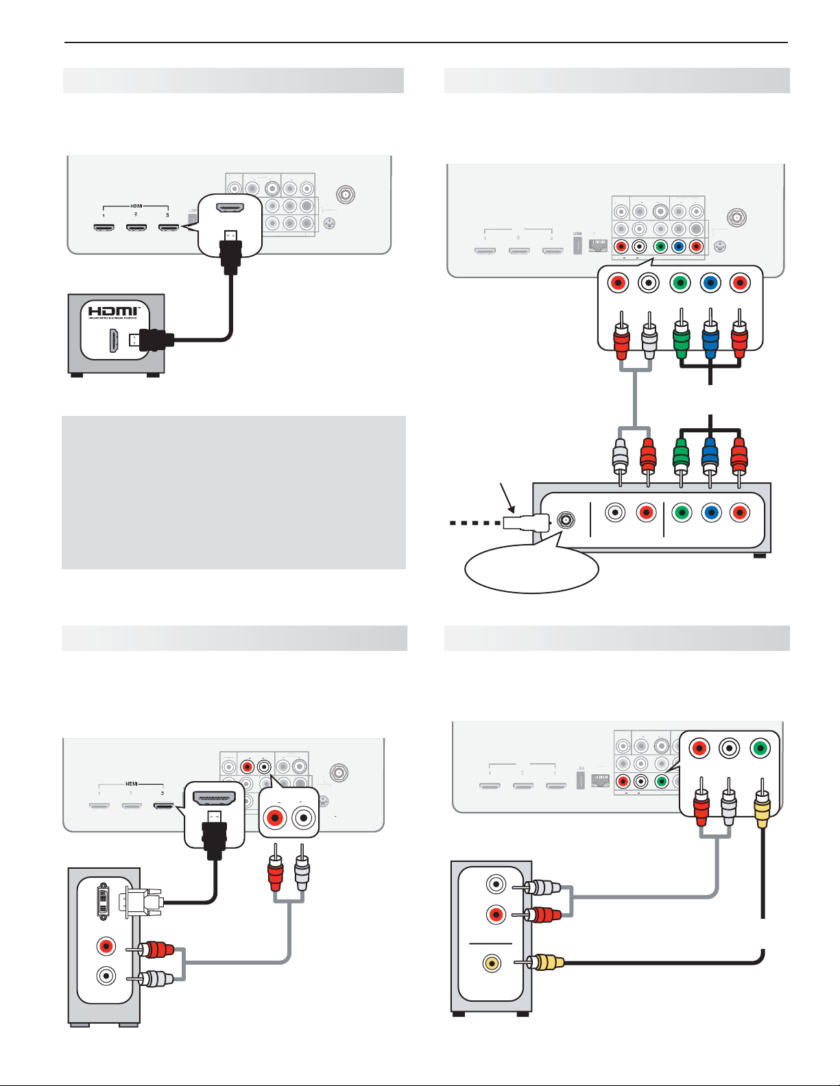
D MI Device
Y Pb Pr Co mponent Video Device
Mitsubishi recommends using high-speed HDMI
cables to connect newer devices incorporating HDMI
technology.
DIGITAL
DIGITA
UDIO
AUDIO
UTPU
OUTPUT
HDMI
2
1
3
AUDIO
AUDIO
AUDI
OUTPUT
Y/ VIDEO
Y/ VIDEO
LR
LR
UTPU
(480i / 480p / 720p / 1080i)
(480i / 480p / 720p / 1080i
DVI/PC
VI/PC
Pb Pr
Pb Pr
INP
ANT
AUDIO
UDI
LR INPUT
3D
LASSE
GLASSES
NPUT 2
INPUT 2
EMITTER
INPUT 1
INPUT
TV main panel
HDMI-to-HDMI
cable
Any HDMI device
HDMI and Digital Surround Sound
738 Series. The TV’s HDMI inputs can receive
digital stereo audio signals only when using the TV
speakers.
Required:
RCA-type component video cables•
Left/right analog audio cables.•
HDMI
HDM
TV main panel
Incoming from
cable service or
satellite dish
LAN
LAN
Audio
cables
DIGITAL
DIGITA
AUDIO
OUTPUT
AUDIO
AUDIO
R
– AUDIO –
ANT
DVI/PC
AUDIO
VI/PC
LR
Pb Pr
Pb Pr
Pb Pr
(480i / 480p / 720p / 1080i)
480i / 480p / 720p / 1080i)
Y/ VIDEO
AUDI
AUDIO
AUDI
OUTPU
OUTPUT
Y/ VIDEO
VIDEO
Y/ VIDEO
/ VIDEO
Y/ VIDEO
LR
LR
UDIO
L
AN
LR INPUT
T
3D
3
GLASSES
GLASSE
NP
INPUT 2
EMITTER
MITTE
T
NP
INPUT 1
Pr
Pb
Component
video cables
838 Series. The TV’s HDMI inputs can receive
digital surround sound from an HDMI device. Use an
HDMI connection if you want to hear digital surround
sound from the TV’s internal speaker array.
DV I Video Device
Required:
DVI-to-HDMI cable or DVI/HDMI adapter and •
HDMI cable
Left/right analog audio cables•
ANT
LR
T
T
3D
GLASSES
NP
INPUT 2
EMITTER
EMITTER
T
L
NP
INPUT 1
L
HDMI
DIGITAL
ITAL
DVI/PC
AUDIO
DVI/P
UDIO
DVI/PC
AUDIO
AUDIO
Y/ VIDEO
VIDEO
Y/ VIDEO
VIDEO
AUDIO
OUTPUT
LR INPUT
L
LR INPUT
Pb Pr
DVI/PC
R INPUT
Pb Pr
(480i / 480p / 720p / 1080i)
(480i / 480p / 720p / 1080i
P
AUDIO
P
AUDIO
UDIO
OUTPUT
UTPU
3
LAN
LR
AUDIO
TV main panel
L
AUDIO
CABLE IN or
Component video
SATELLITE IN
Comp osite Video Device
Required:
Composite video cable (usually yellow)•
Analog stereo audio cables.•
DIGITAL
IGITA
AUDIO
AUDI
OUTPUT
OUTPUT
HDMI
TV main panel
L
LAN
AUDIO
UDIO
AUDIO
R
device
AUDIO
AUDI
OUTPUT
Y/ VIDEO
Y/ VID
Y/ VIDEO
VID
Y/ VIDEO
LR
LR
DVI/PC
LR
Pb Pr
Pb Pr
(480i / 480p / 720p / 1080i)
480i / 480p / 720p / 1080i
PbYPr
LR INPUT
NPUT
INPUT 2
R
– AUDIO –
NPUT 1
INPUT 1
3D
D
LASSE
GLASSES
EMITTE
EMITTER
ANT
Y/ VIDEO
L
AUDIO
Audio
cables
VCR or other device with
composite video output
Composite
video cable
DVI OUT
R
L
AUDIO
DVI-to-HDMI
cable
Digital DVI
Audio
cables
R
AUDIO OUT
COMPOSITE
VIDEO OUT
device
For assistance call 1(800) 332-2119
Page 12
12 2. TV Connections
OUTPU
2
1
D
L
O
O
T
D
(
)
L
R
O
PbP
r
O
S
E
O
R
O
b
2
1
D
O
O
DVI/PC
(
)
L
T
Y
PbP
r
Y/
D
GLASSES
ANT
O
L
R
O
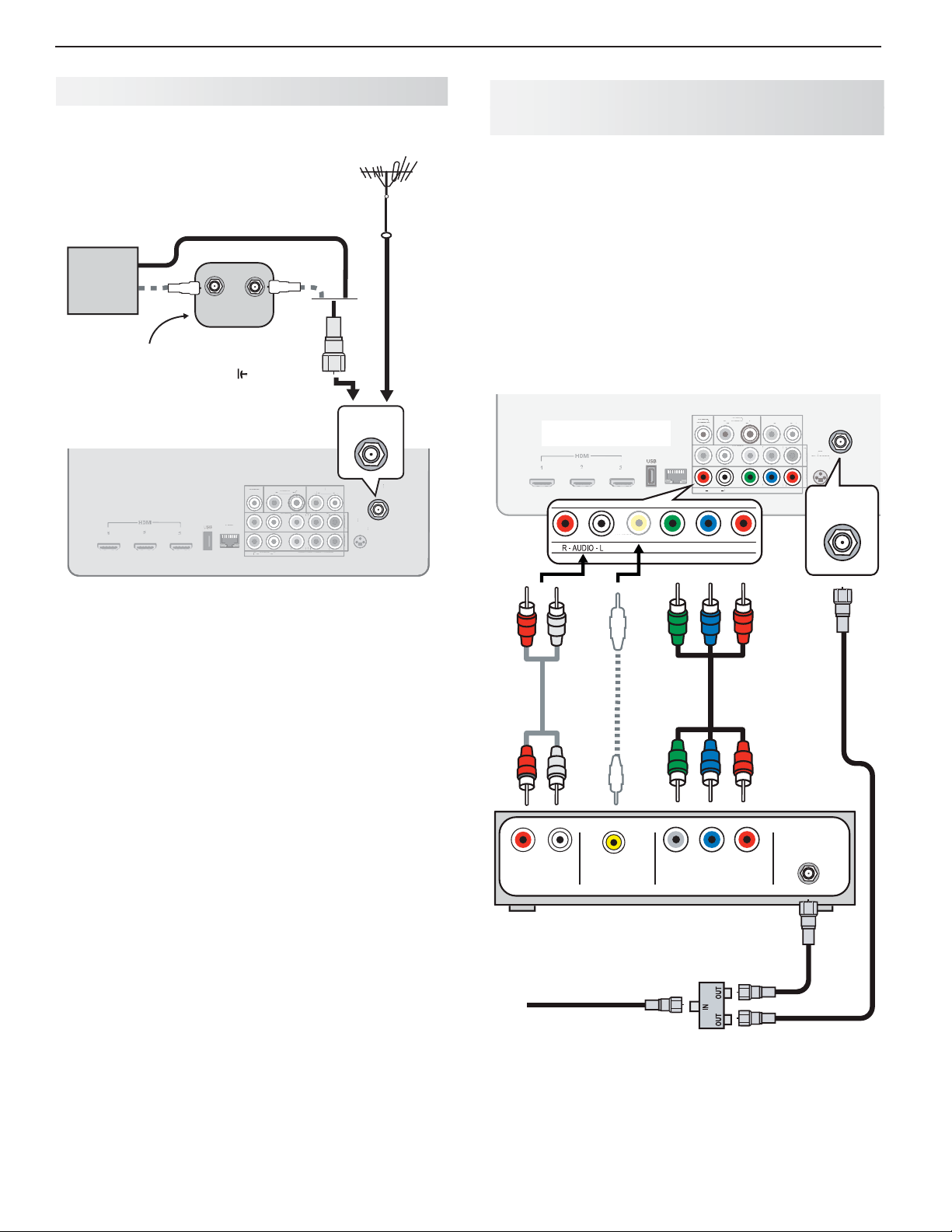
Ante nna or Cable TV Service
Connect the incoming cable to the TV’s
Direct cable (no cable box)
OUT
DIGITAL
IGITA
AUDI
AUDIO
UTPU
OUTPUT
AUDIO
AUDI
AUDIO
AUDIO
OUTPUT
Y/ VIDEO
Y/ VIDE
Y/ VIDEO
Y/ VIDE
LR
or
LR
L
T
(480i / 480p / 720p / 1080i)
480i / 480p / 720p / 1080i
DVI/PC
VI/PC
Pb Pr
b
Pb Pr
INPUT
Cable TV
service
IN
Older cable box
Not recommeded. Other
connection types provide
better quality audio and video.
TV main panel
LAN
ANT
input.
Antenna
or
ANT
AUDIO
AUDIO
LR INPUT
3D
3D
GLASSES
GLASSE
INPUT 2
INPUT
EMITTER
MITTER
NPUT
INPUT 1
VCR or DVD Recorder to an
Antenna or Wall Outlet Cable
Required:
1. V ide o cable s
1a. Component video cables (red/blue/green)
or
1b. Composite video cable (usually yellow)
2. Left/right analog audio cables.
3. Two-way RF splitter
4. Two coaxial cables
Note: If your recording device has an analog-only
tuner, you must use a digital converter box to
enable recording of digital broadcasts.
ANT
DIGITAL
IGITAL
AUDI
AUDIO
OUTPUT
TV main panel
ANT
ANT
Y/ VIDEOY/ VIDE
Y/ VIDEO
UTPUT
LAN
AUDIO
AUDI
AUDIO
Pb
AUDIO
AUDI
OUTPUT
OUTPUT
Y/ VIDEO
/ VIDEO
Y/ VIDEO
VIDEO
Y/ VIDEO
LR
LR
Pr
DVI/PC
LR
R INPU
Pb Pr
Pb Pr
Pb Pr
(480i / 480p / 720p / 1080i)
480i / 480p / 720p / 1080i
AUDIO
AUDIO
ANT
LR INPUT
3D
3
GLASSES
INPUT 2
INPUT
EMITTER
INPUT 1
INPUT
ANT
1b.
2.
L
R
AUDIO OUT
Composite
COMPOSITE
VIDEO OUT
or
video cable
DVD Recorder or VCR
Incoming cable
1a.
COMPONENT
VIDEO OUT
3.
RF Splitter
ANTENNA
IN
4.
4.
For assistance call 1(800) 332-2119
Page 13

2. TV Connections 13
PbP
r
1
D
)
Y/
E
O
b
Y/
E
O
D
INPUT
A
3
GLASSES
A
L
R
LAN
C
INPUT
O
INPUT
PbP
r
1
D
O
)
E
O
b
E
O
INPUT
O
3
GLASSES
A
L
R
LAN
A/ V Receiver
Most setups require either a digital audio cable or
analog stereo audio cables. To send audio from TV
channels received on the
nected directly to the TV, you must use one of the connections shown below.
The TV makes all audio available in digital and analog
formats:
Analog audio coming into the TV is available as •
output in digital stereo format on the
AUDIO OUTPUT
Digital incoming audio is available as analog output •
on the
AUDIO OUTPUT L
TV main panel
Digital coaxial
cable (for a digital
A/V receiver)
jack.
ANT
input or devices con-
and R jacks.
DIGITAL
IGITAL
DIGITAL
DVI/PC
AUDIO
VI/PC
UDIO
AUDIO
AUDIO
AUDIO
LR INPUT
Y/ VIDEO
VID
Pb Pr
Pb Pr
Y/ VIDEO
VID
(480i / 480p / 720p / 1080i)
AUDIO
LR
(480i / 480p / 720p / 1080i
UDIO
DIGITAL
LAN
AUDIO
OUTPUT
OUTPUT
OUTPUT
OUTPUT
or
Stereo analog
cables (for an
analog A/V
receiver)
DIGITAL
AUDIO
LR
OUTPUT
GLASSES
INPUT 2
INPUT 2
EMITTER
INPUT 1
INPUT
ANT
3D
D
AUDIO
OUTPUT
LR
A/ V Receiver with HDMI Output
Required: One HDMI-to-HDMI cable
This option allows you to view content from devices
connected to an A/V receiver. The A/V receiver can
send audio and video to the TV over a single HDMI
cable. You can use an HDMI connection as described
here in addition to an audio connection from the TV’s
audio output. The optional audio connection allows you
to hear, through the A/V receiver, devices connected to
the TV only, e.g., an antenna on the
838 Series:
This setup allows you to use NetCommand-controlled audio and video switching
over the HDMI cable. See the full owner’s guide at
www.mitsubishi-tv.com for details.
DIGITAL
IGITAL
DIGITAL
AUDI
AUDIO
AUDIO
OUTPUT
OUTPUT
OUTPUT
HDMI
2
1
3
LAN
TV
HDMI cable
ANT
DVI/PC
AUDIO
DVI/PC
AUDI
LR INPUT
Y/ VIDEO
Y/ VID
Pb Pr
DIGITAL
AUDIO
OUTPUT
Pb Pr
Y/ VIDEO
Y/ VID
(480i / 480p / 720p / 1080i)
AUDIO
LR
(480i / 480p / 720p / 1080i
UDIO
Optional
analog or
digital audio
connection
input.
AUDIO
LR
OUTPUT
GLASSES
INPUT 2
INPUT 2
EMITTER
OUTPUT
INPUT 1
INPUT
3D
D
AUDIO
ANT
LR
Note:
PTICAL
OPTICAL
INPUT
COAXIAL
OAXIAL
COAXIAL
INPUT
INPUT
A/V receiver back panel
On rare occasions, an HDMI signal may be •
copy-restricted and cannot be output from
the TV as a digital signal. To hear these copyprotected signals through the A/V receiver, use
the connection for an analog A/V receiver.
Check the A/V receiver’s Owner’s Guide for •
information concerning use of the digital input
and switching between digital sound and
analog stereo sound from the TV.
A/V receiver with
HDMI output
Any connection
types
High-definition
DVD player
HDMI OUT
Cable box
DIGITAL
AUDIO IN
ANALOG AUDIO IN
LR
VCR
DVD player
For assistance call 1(800) 332-2119
Page 14
14
TV Features
3
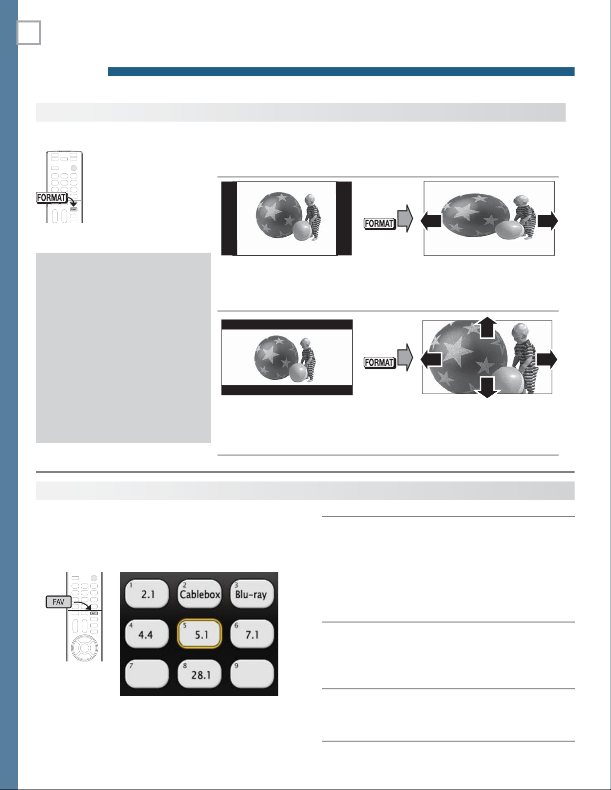
The FO RMAT Key and Picture Shape
Repeatedly press the
FORMAT
through displays available for the current
program. The TV will
remember the format
you last used on each
input.
Black bars at the edges of the
picture are common in HD
pictures. Black bars are not a
defect of the TV.
Black bars are added by broad-•
casters to fill the 16:9 screen
area while preserving the original
aspect ratio of the picture.
Your cable box or satellite •
receiver may also be altering
the broadcast picture. If your
receiver offers output in native
format, try using it with Mitsubishi’s picture formats.
key to cycle
Important
Sample Uses of the
You can use the
edges of the picture.
Squarish 4:3 image is
narrower than the 16:9
screen; unused areas at the
sides are filled with black.
Wide 2.35:1 anamorphic DVD
image; unused areas at the
top and bottom are filled with
black (letterbox effect).
FORMAT
FORMAT
key to reduce or eliminate black areas at the
Key
Press
Wide Expand mode stretches
the picture sideways to fill the
screen.
Press
Zoom mode. The picture fills
the screen. All four edges are
cropped in this mode.
FA V ( Favorites)
FAV
The
sources. Sources can be channels from the
or devices connected to the TV. You can store up to
nine favorites.
Sample Favorites menu. Switch to favorite channels or
inputs using number keys.
For assistance call 1(800) 332-2119
key gives you quick access to favorite program
ANT
input
Press 1.
INPUT
and switch the TV to the input
you want to add. If adding a channel, switch
to the
ANT
input and tune to the channel.
Press the 2.
Adding
Removing
Selecting
Move the highlight to the number position 3.
you want to assign to the channel or input.
Press 4.
While watching TV, press the 1.
In the 2. Favorites menu, highlight the channel
or input you want to remove.
Press 3.
While watching TV, press the 1.
Press the number key for the channel or 2.
input you want.
FAV
ENTER
CANCEL
key.
.
.
FAV
FAV
key.
key.
Page 15

3. TV Features 15
US
INPUT 3
O
LRP
b
E
O
P
Ch annelView Channel Listings
ChannelView displays program descriptions sent by
broadcasters. This information may be unavailable
in some areas.
About ChannelView
ChannelView™ shows memorized channels on the ANT
input. It displays channel names and program information
for digital channels. No program information is displayed
for analog channels.
ChannelView allows you to set up three banks of custom
channels for convenient access. You can save groups of
channels by content (e.g., news, sports, children’s programming) or by TV user.
Note: You must fi rst set the TV Clock ( page 24 ) to
receive ChannelView listings.
Press 3.
Press 4.
to highlight a bank.
MENU
to see channels in the bank.
To allow tuning to any channel in memory, select •
the All bank.
Phot os and Moving Video as
Composite Video
Note: 838 series TVs can display photos and play mu-
sic from a USB drive. See the detailed owner’s
guide at www.mitsubishi-tv.com.
Connect the camera to the TV using a composite video
cable and control the slide show or movie through the
camera. The display resolution will be standard-definition (480i).
Refer to the owner’s manual supplied with the
1.
camera for instructions needed for this setup.
Set the camera’s output signal type to
2.
put the camera into playback mode.
With the camera still turned on, connect your digital
3.
camera’s composite video cable (usually yellow) to
the TV’s
camera’s audio output cable to the
Y/VID EO
jack. To hear audio, connect the
NTSC and
AUDIO L
jack.
ChannelView, “All” tab. Programs for the tuned channel
are listed on the right.
Chann elView Custom Channel Banks
Select a channel bank to customize.
Press
1.
2.
Press
GUIDE
to display ChannelView.
MENU
to move the highlight to the bank
header.
Press
3.
With the bank name highlighted, press
4.
to select Bank 1, 2, or 3.
ENTER
to
enter setup mode where you can select channels to
include in the bank.
Press
5.
EXIT
when finished with setup.
Using Custom Channel Banks
While watching TV, press •
tune only to channels stored in the current bank.
To • change to a different channel bank:
Press 1.
GUIDE.
Press 2.
MENU.
CH
/ . The TV will
INPUT 3
Pb
Pr
r
Y/ VIDEO
Y/ VID
Y/ VIDEO
LR
L
AUDIO
AUDI
AUDIO
USB HDMI 4
B
Optional
Audio Cable
Camera connection using a composite video cable
When the
4.
New Device Found screen displays,
assign the name Camcorder.
Press
5.
6.
7.
EXIT
to close the New Device Found screen.
Highlight the icon for the camera input and press
ENTER
.
If viewing photos, control the slideshow from the
camera. Advance through the images manually or
check if the camera can advance automatically.
For assistance call 1(800) 332-2119
Page 16

16 3. TV Features
3D
GLASSES
EMITTER
3 D Video
To display 3D gaming or 3D cinema content, your
Mitsubishi TV requires:
A compatible 3D source device outputting a 3D •
signal in one of these formats:
Checkerboard format, 1080p, 60-Hz; (lower resolutions may be supported but will not fill the
screen)
Side-by-Side format, 1080p, 24/30/60 Hz; 720p, 60 Hz
Active-shutter 3D glasses, DLP link type or IR •
emitter type with matching emitter
Please visit our website at www.mitsubishi-tv.com for information about future TV software updates that will broaden
3D signal compatibility.
Initial Setup
If your 3D glasses came with an emitter box,
1.
connect the emitter box to the
EMITTER
jack. Place the box in front of the TV
where there is a clear path to the glasses.
Note: If your glasses are marked DLP Link, skip this
step; no emitter box is required with DLP Link
technology.
3D GLASSES
Watching 3D Video
Note: Active 3D glasses are required.
Press
1.
2.
3.
4.
5.
6.
INPUT
.
Highlight the icon for the 3D video device and press
ENTER
.
Press
MENU
and select the Picture > 3D Mode
menu.
Select
On
for 3D Mode
. The On setting will be
memorized for the current input when you exit this
menu.
Select the
Source Format. If your source device
outputs an unsupported signal format see “Notice
Concerning Format Compatibility” on this page .
For
Glasses Control, select the control type for
your 3D glasses, either IR Emitter or DLP Link.
SUB
CENTER
WOOFER
INPUT
OUTPUT
DIGITAL
AUDIO
AUDIO
LR
OUTPUT
OUTPUT
IR-NetCommand
Output/EXTERNAL
CONTROLLER INPUT
HDMI
2
1
3
Power on the TV and the source device.
2.
Connect the source device to the TV’s HDMI input.
3.
When the
4.
Y/ VIDEO
LAN
Y/ VIDEO
(480i / 480p / 720p / 1080i)
AUDIO
LR
New Device Found screen displays,
Pb Pr
Pb Pr
ANT
DVI/PC
AUDIO
LR INPUT
3D
GLASSES
INPUT 2
EMITTER
INPUT 1
name the input.
Press
5.
EXIT
to close the New Device Found screen.
Use the Picture > 3D Mode menu to enable 3D video.
Press
7.
8.
EXIT
to close the menu.
If the image does not appear correct
appear to be moving in instead of out),
(e.g., objects
open the
Picture > 3D Mode menu and set Glasses L-R to
Reverse.
To Watch Regular (non-3D) Video
The 3D Mode setting is memorized for each input.
When you want to watch non-3D video on the input
selected above, open the Picture > 3D Mode menu
and set 3D Mode to Off.
Notice Concerning Format Co mpatibility
Mitsubishi 3DTVs (738 and 838 series) currently support
the side-by-side 3D signal format. For support of other 3D
formats, such as top-bottom and frame packing (3D Blu
Ray standard), Mitsubishi 3DTVs will require the use of a 3D
For assistance call 1(800) 332-2119
source device that outputs the 3D checkerboard format or
a 3D source device coupled with the Mitsubishi 3D adapter.
In all cases an emitter and matching 3D active shutter
glasses or DLP Link active shutter glasses are required in
order to view 3D content.
Page 17

3. TV Features 17
3 D Video, continued
3D Safety Requirements
3D Glasses are NOT designed as sunglasses or •
safety glasses and do not provide protection. 3D
glasses should be worn only when viewing 3D
material.
Do not wear the wireless glasses in any situations •
that require unimpaired visual perception.
Chi• ldren under the age of 5 should not view 3D
programming.
Under normal conditions, 3D viewing is safe for your
movies or games. Some people may experience discomfort, however. To minimize the potential for experiencing visual problems or any adverse symptoms:
Read and follow any and all safety warnings that •
accompany your 3D glasses or 3D source devices.
Maintain a distance of no less than 2 to 2.5 times •
the screen height measurement away from the
display. Viewing from too short a distance can
strain your eyes.
Take regular breaks, at least 5 minutes after every •
hour of 3D viewing.
If you experience any of the following symptoms, discontinue 3D viewing until the symptoms go away:
nausea, dizziness, or queasiness, •
headache, or eyestrain, •
blurry vision,•
d• ouble vision that lasts longer than a few seconds,
Do not engage in any potentially hazardous activity
(for example, driving a vehicle) until your symptoms
have completely gone away. If symptoms persist,
discontinue use and do not resume 3D viewing without
discussing your symptoms with a physician.
Do not use the glasses where loss of balance or limiting your field of vision may be dangerous to you.
Do not use near staircases, ledges or balconies. You
may risk falling during or after use.
Epilepsy
WARNING! IF YOU OR ANY MEMBER OF YOUR
FAMILY HAS A HISTORY OF EPILEPSY, CONSULT
A PHYSICIAN BEFORE USING 3D VIDEO OR GAME
PRODUCTS.
A small percentage of the population may experience
epileptic seizures when viewing certain types of TV
images or video games that contain flashing patterns of
light.
The following people should consult a physician before
viewing 3D Games or Video:
Any• one with a history of epilepsy, or who has a
family member with a history of epilepsy
Anyone who has ever experienced epileptic sei-•
zures or sensory disturbances triggered by flashing
light effects.
WARNING! SOME LIGHT PATTERNS MAY INDUCE
SEIZURES IN PERSONS WITH NO PRIOR HISTORY
OF EPILEPSY. DISCONTINUE 3D VIEWING IF YOU
EXPERIENCE ANY OF THE FOLLOWING SYMPTOMS:
Invol• untary movements, eye or muscle twitching
Muscle cramps•
Nausea, dizziness, or queasiness•
Convulsions•
Diso• rientation, confusion, or loss of awareness of
your surroundings
Do not engage in any potentially hazardous activity (for
example, driving a vehicle) until your symptoms have
completely gone away.
Do not resume 3D viewing without discussing the
symptoms with your physician.
For assistance call 1(800) 332-2119
Page 18
18 3. TV Features
AUDIO
LR
AUDIO
L
Soun d Projector
838 Series
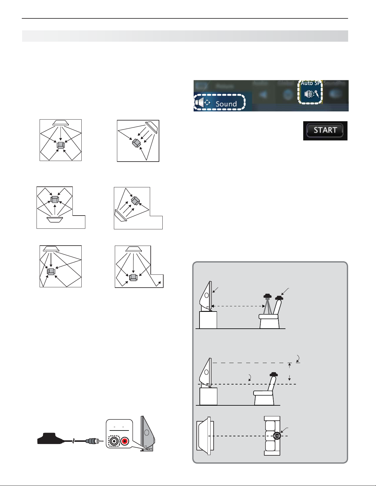
The TV’s built-in speaker array can be set up to reflect
sound off the room walls to create a surround sound effect.
Positioning the TV
Center the seating area in front of the TV and at •
least six feet away.
Arrangements that give good results:•
If the room is an odd shape, locate the TV to take •
best advantage of wall reflections.
Place the microphone as described in the guide-
3.
lines.
Press
4.
5.
6.
7.
Note: Do not perform manual adjustments after run-
8.
MENU
and go to Sound > AutoSP.
Highlight
Quietly exit the room right away. The calibration
sequence may be loud.
before returning to the room.
Play some sample audio material to check the
sound quality.
Store the microphone out of direct sunlight and
away from heat.
START and press
ning auto setup as doing so will delete all autosetup results.
ENTER
.
Wait for completion of setup
Avoid locations that may distort sound reflections.•
Connecting the TV
To hear digital surround sound, the TV must be connected to a digital surround sound source. The surround
sound source can be on an HDMI input or the
(for some digital broadcasts). Other stereo connections
will provide Dolby Pro Logic surround sound.
ANT
input
Auto Se tup
Auto setup uses the included calibration microphone. For manual setup, see the full owner’s guide at
www.mitsubishi-tv.com.
Power on the TV and external subwoofer, if any.
1.
Plug the microphone cable into the TV’s
2. INPUT 3
left audio jack.
Micropho ne Placement
TV
6 ft. minimum
Maximum height above speakers
Height of TV
speakers
Microphone
Set the microphone
on a level surface at
ear height at least
six feet from the TV.
Use a seat backrest
or tripod so as to
pick up sound from
all directions.
Be sure the
3 ft.
height of the
microphone is
within three feet
of the speaker
height.
For assistance call 1(800) 332-2119
Microphone
Center the microphone in front of
the TV.
Page 19

3. TV Features 19
SUB
O
b
2
1
DIG
AUDIO
OUTPUT
(
)
(pp)
O
P
b
O
D
GLASSES
E
R
ANT
A
L
R
D
O
L
R
I
d
Output/
L
C
INPUT
SUB
R
T
Pb P
Y/ VIDEO
PbP
r
(
)
(pp)
Y/ VIDEOb
P
r
Y
3
GLASSES
AUDIO
L
N
A
L
R
b
Y/
E
O
P
r
H
StreamTV™ Internet Media
Internet services provided by VUDU™ Apps let you
access many popular on-line applications. In addition to
free content, VUDU’s movie service lets you buy and rent
movies through the TV. Visit www.VUDU.com to learn
more about available movie titles, prices, and services
offered. For a list of recommended routers and switches,
see the Support > FAQ section at VUDU.com.
Home N etwork Setup
Before using StreamTV internet media, you must connect
the TV to the internet using one of these methods.
Ethernet Connection
DHCP (automatic)
Connect the TV to your network router with a Cat-
1.
egory-5 Ethernet cable
TV Main Panel
(not supplied).
ENTER
CENTER
WOOFER
WOOFE
INPUT
OUTPUT
OUTPU
IR-NetCommand
R-NetComman
Output/EXTERNAL
EXTERNA
LAN
LAN
DIGITAL
ITAL
AUDIO/SURROUND
AUDIO/SURROUN
AUDIO
AUDI
AUDIO
LR
OUTPUT
OUTPUT
OUTPUT
LAN
Y/ VIDEO
Y/ VIDE
Pb Pr
PbPrY/ VIDEO
Y/ VIDE
(480i / 480p / 720p / 1080i)
480i / 480p / 720p / 1080i
AUDIO
LR
UDIO
ANT
OUTPUT
UTPUT
LR
3D
3
GLASSES
INPUT 2
INPUT
EMITTER
MITTE
INPUT 1
INPUT
Required for StreamTV internet media:
Broadband internet service (at least 2 Mbps for SD, 4 Mbps •
for HD, and 8 Mbps for 1080p HDX)
Ethernet cable • or an Azurewave AW-NU231 USB
wireless adapter.
Computer access to the VUDU.com website (required •
for initial account activation).
A credit card for rental and purchase transactions •
from VUDU’s movie service.
Setup > Network menu
Highlight the desired network and press
4.
connect. A check will appear next to the connected
network.
ENTER
to
Router or modem
Incoming
internet
cable
Open the
2.
Press
3.
providing high-speed
internet service
Ethernet
cable
Setup > Network menu to review settings.
EXIT
to clear the menu.
Manual
Connect the TV to your network router with a Cat-
1.
egory-5 Ethernet cable
In the
2.
3.
4.
5.
Setup > Network menu, highlight Manual and
press
ENTER
.
Press
to move to the Connection Data area.
Input the connection data.
After entering connection data, press
(not supplied).
ENTER
connect.
Change any of the following if needed:
6.
Default Gateway•
DNS•
Subnet Mask•
Wire less Connection
Disconnect the Ethernet cable if present.
1.
Connect an Azurewave AW-NU231 USB wireless
2.
adapter to the TV’s USB port.
Open the
3.
Setup > Network menu. After a few
seconds, detected networks will appear listed on
the screen in order of signal strength.
to
Setup > Network menu after connecting. The active
network is checked and connection data displays.
If connecting to a secure network, enter the
5.
network key or password on the remote control
when prompted.
IEEE 802.11n-compliant
wireless network router
providing
high-speed
internet service
Wireless
adapter
Incoming
internet
cable
Wireless
adapter
r
3D
PbPrY/ VIDEO
(480i / 480p / 720p / 1080i)
480i / 480p / 720p / 1080i
INPUT 2
INPUT 2
INPUT 1
INPUT 1
GLASSES
EMITTER
D
HDMI
2
LAN
LA
/ VIDEO
AUDIO
LR
R
Back of 738
Series TV
OR
INPUT 3
LR
Pb
Y/ VIDEO
Pr
P
VID
AUDIO
UDIO
USB HDMI 4
DMI 4
838 Series
TV
Connecting the USB wireless adapter
For assistance call 1(800) 332-2119
Page 20

20 3. TV Features
StreamTV™ Internet Media, continued
Using StreamTV Internet Media
After establishing internet connectivity, press the
services from VUDU Apps. Press
ENTER
to launch an application.
Getting Started with V UDU
Movies
After establishing internet connectivity, press
1.
INTERNET
Select the VUDU movie service.
2.
Browse the VUDU movie catalog and offerings.
3.
When you are ready to rent or buy a movie, you
4.
will be prompted to activate your VUDU account.
Follow the on-screen instructions and use a computer to go to www.VUDU.com/activation. A
credit card is required for activation.
Once your account is activated, you can rent and buy
movies using only the TV and the TV’s remote control.
Specialized Keys for VUDU
INTERNET
to display offerings from VUDU.
key to display
INTERNET
Wir eless Audio Playback
838 Series. The TV’s built-in speaker array can play
audio from a handheld device using Bluetooth® A2DP
(stereo audio) wireless technology.
Pairing the TV with an Audio Device
Turn on the wireless device you wish to use for
1.
back. Turn off all other wireless devices in the area as
the TV can pair with only one device at a time.
Press
2.
Bluetooth® icon in Input Selection Menu
3.
4.
5.
INPUT
to display the Input Selection menu.
Highlight the
Pair your device with the TV and then connect.
Some devices pair and connect automatically,
while others require you to enter the TV pass code
displayed.
Use keys on the TV’s remote control to control playback. Not all keys work for all devices.
Bluetooth icon and press
ENTER
play-
.
INTERNET
GUIDE
INFO
LAST
CANCEL
F2
EXIT
Displays the VUDU internet menu.
VUDU
VUDU
VUDU
VUDU backspace (in text-entry screens)
VUDU System menu
Exit VUDU
HOME
key
MORE
key
BACK
key (goes to previous menu)
Troubleshooting
If You Are Unable to Connect to the Internet
Check all power and data connections.•
If you can reach the internet with a computer or •
other device on the same internet service used by
the TV, consult the router or modem owner’s guide
for reset instructions.
If you cannot reach the internet, contact your •
service provider. You may be asked for network
information such as the TV’s IP address. Go to the
Setup > Network menu to see connection data.
For Further Assistance
If you are having trouble connecting your TV or •
accessing internet applications, contact Mitsubishi
Customer Care at 1-800-332-2119.
If you are having difficulty with your VUDU •
account, contact VUDU Customer Care at
www.VUDU.com/support.
See more troubleshooting tips in • Appendix C .
Skip a track
(
PAUSE
(
STOP
(
REVERSE
(
PLAY
(
FORWARD
)
)
)
)
)
Resetting Bluetooth Pairing or Connection
Perform this reset if the audio device does not connect
properly to the TV.
If the audio device has been previously paired with
1.
the TV, delete the TV from the device’s paired list.
Go to the TV’s
2.
the Bluetooth icon. Press
Press
3.
4.
5.
EXIT
Go to the
Bluetooth icon. Press
Press
EXIT
Inputs > Name menu and highlight
ENTER
to select Off.
.
Inputs > Name menu and highlight the
ENTER
to select On.
.
Tips for Wireless Playback
Selecting the • Bluetooth icon at a later time will
reconnect the TV to the paired device.
If the paired device is not available, the TV will •
accept pairing from a different device.
Once connection is lost, the TV will power off after •
five minutes without receiving a signal.
To clear a paired device, turn off the • Bluetooth icon
(Inputs > Name menu) or pair the TV with a different device.
For assistance call 1(800) 332-2119
Page 21

4
21
TV Menus
Press
MENU
on the remote control to open the m ain menu and access these settings.
Pi cture
Picture Vide o Settings in this menu are saved for the current input only.
From the Picture > Video menu
Press 1. to highlight an option
Press 2. to adjust.
P icture
Mode
Contrast In most home lighting situations, medium contrast looks best. Stored for each Picture Mode.
Brightness
Color Adjusts overall color intensity from monochromatic to fully saturated. Saved by input.
Brilliant
Game
Bright For most daytime viewing
Natural For most nighttime viewing
Advanced Modes. Contact your professional installer for setup.
Adjusts overall picture brightness. Stored for each Picture Mode.
For use under bright light.
Optimizes picture and video processing for game consoles.
Available only when the input name is
While watching TV
Press the 1.
Press 2. to select a video option.
Press 3.
Game
or PC.
To make picture adjustments:
VIDEO
key.
to change the setting.
Set the Picture Mode
before changing other
video settings, Use Picture
Modes to get the best
image under different
viewing conditions.
Tint Adjusts the red-to-green ratio. Saved by input.
Sharpness Adjusts picture detail and clarity. Saved by input.
Color Temp
Video Noise
EdgeEnhance
DeepField
Imager
Picture
Screensaver
Film Mode 480i and 1080i signals only.
Smooth 120
Test
Picture
)
High
gives white a cool cast.
Reduces minor noise (graininess) in the picture. Saved by input.
EdgeEnhance™ makes the image appear sharper. Saved by input.
Provides strong contrast with detail over mixed screen content. Demo displays a split picture to
show On (right side) and Off (left side). Saved by input.
Pi cture+
Displays a screensaver pattern while playing an audio-only source.
tion to movies filmed at 24 frames per second. Try the
Setting saved by input.
Smooth 120 reduces motion blur in action scenes but may show pixel structure during slower motion or in still
images. Works in conjunction with Film Mode.
Displays a test picture.
(Picture Plus)
Low gives white a warm cast. Stored for each Picture Mode.
In
Auto
, the TV automatically detects and applies film-decoding correc-
Off
setting if images show many jagged edges.
For assistance call 1(800) 332-2119
Page 22

22 4. TV Menus
Picture, continued
Picture Reset
Picture Pe rfect
(PerfectColor/PerfecTint) 838 Series. Sliders let you adjust the saturation (intensity) and
hues of six separate colors for the current image source.
Resets sound and picture adjustments for the current input. Highlight the • Reset icon
and press
Reset• has no effect on universal settings (Balance, Listen To, Language) or on
Advanced picture settings.
ENTER
twice to perform reset
.
Picture
Adv anced
Advanced Modes. Contact your professional installer for setup.
738 Series. Special/ADV.
838 Series. ISF Day/ADV1, ISF Night/ADV2
Picture 3 D Mode
See page 16 .
S ound
Sound Au dio Settings in this menu are saved for the current input only. To make audio adjustments:
TV Speakers
(sound source)
Sub woofer
From the Sound > Audio menu
Press 1. to highlight an option
Press 2.
On Turns on the internal TV speakers.
Off
Center 838 Series.
[Subwoofer
level adjustment]
to adjust.
Turns off the internal TV speakers so you hear sound only through a connected device
(A/V receiver or headphones).
Makes the TV’s speaker array act as a center channel. See the
detailed owner’s guide at www.mitsubishi-tv.com for use of this feature.
838 Series. Adjusts the volume level of a connected subwoofer. Set Sound >
Global > Subwoofer to On to make this adjustment available.
While watching TV
AUDIO
Press the 1.
Press 2.
Press 3. to change the setting.
key.
to select an audio option.
Bass Controls bass sound from the TV speakers.
Treb le Controls high-pitched sound from the TV speakers.
Balance Controls audio balance between the right and left TV speakers (Sound Mode Stereo only)
Sou nd Mode Stereo No special audio effects from the TV speakers
Surround Modifies audio from the TV speakers.
• For monaural (non-stereo) programs, creates a simulated stereo effect.
• For stereo programs, creates a simulated surround sound effect.
• 838 Series. The TV’s speaker array plays surround sound if available.
Music 838 Series. Optimizes the TV’s speaker array for music listening.
Night 838 Series. Focuses the TV’s speaker array to a single point to limit sound heard
by others outside the room. Press
ENTER
to adjust the focal point (Night Angle).
For assistance call 1(800) 332-2119
Page 23

4. TV Menus 23
Sound, continued
Level Sound On, Off Reduces differences in sound volume between programming segments.
Analog Li sten To
(For
antenna
analog channels)
Sound Glo bal
Stereo The TV plays stereo broadcasts in stereo and mono broadcasts in mono.
SAP Second Audio Program. Selects an additional monaural sound track.
Mono Reduces background noise. Use when receiving a weak stereo audio signal.
838 Series. Settings in this menu apply to all inputs.
An alog Audio
Out
Subwoofer Select On to turn on audio to a connected subwoofer. Set to Off if no subwoofer is connected.
Center Channel On allows the TV’s speakers to complement your external sound system as a center channel. Set
These settings affect audio from the AUDIO/SURROUND OUTPUT jacks.
Fixed Use with an analog A/V receiver.
Variable Use with headphones; adjust headphone volume using the TV’s remote control.
Re ar
to Off if not in use.
838 Series. Use when supplementing the TV’s speaker array with external rear speakers.
Sound Auto Sp
838 Series. See page 18 for setup instructions.
Sound
SoundPro
838 Series. Lets you set up the Sound Projector speaker array manually. See the
detailed owner’s guide at www.mitsubishi-tv.com.
C aptions
Captions
Services
Service On if Mute: Displays digital closed-caption signal Caption 1 (digital) or CC1 (analog) when audio from the
Digital
Analog
Captions
Captions
TV speakers is muted. While watching TV, press
Caption 1–Caption 6:
CC 1–CC 4.• Standard closed-caption signals
Tex t 1–Text 4 . • Text-service signals
Caption signals sent by the broadcaster.
Font
As Broadcast changes settings to those selected by the captions provider, or, if none, to
the TV’s own caption defaults.
Color
A white font on a black translucent background makes an easy-to-read combination.
MUTE
to turn closed captions on/off.
For assistance call 1(800) 332-2119
Page 24

24 4. TV Menus
Setup
Setup
La nguage
Select either English or Spanish for on-screen menus.•
Select the language for a digital program from the •
ANT
input (if available).
Setup Cl ock
Set the TV clock to:
Use the TV Timer to power on the TV automatically at a preset time•
Receive correct updates to ChannelView listings•
Note: When the Daylight Savings Time change occurs, you must open this menu and set the TV’s clock ahead or back.
Setup T imer
The Timer tells the TV to power on automatically at a time you set. Use this menu to set a day,
time, input, and channel for the Timer. If the TV is already on at the set time, the TV will automatically change to the designated channel or input.
• The TV clock must be set before you can use the Timer feature.
• As a reminder that the TV Timer is set, the TV
•
When the Timer turns on the TV, press any key on the remote control to keep it from turning off after five minutes.
Setup
Cha nnel
See “Memorizing Channels with Channel Scan” on page 7 to scan for all available channels
on the
ANT
input.
POWER
indicator flashes slowly while the TV is powered off.
E dit
After channel scan, Edit lets you add and delete memorized channels.
• Press
• Press
Adding/Deleting Channels Using the Channel Edit Menu
PAGE
/ to jump to the next or previous page of channel numbers.
to move through all channel numbers, one at a time.
Channels marked with a check are in memory.•
To add or delete a channel from • memory, highlight the channel number and press
To add a single digital channel not in the list, see the full owner’s guide at www.mitsubishi-tv.com.•
Setup Energy
La mp
Energy
Blue Glow
(838 series)
Standard,
Bright
On, Off Select On to see blue accent lighting when the TV is powered on.
Standard is for most viewing conditions. Use Bright in brightly lit rooms. You may
notice increased fan noise when using the Bright setting.
Home
Setup
Network
Ethernet Connection
Wireless Connection
See “Home Network Setup,” page 19 .
ENTER
.
For assistance call 1(800) 332-2119
Page 25

4. TV Menus 25
Input s
Inputs N ame
Lets you assign or • change names of inputs appearing in the Input Selection menu.
Inputs Learn
Inputs AVR
Highlight the input and press •
Lets you turn the • Ant input On/Off (to display or hide it in the Input Selection menu).
838 Series.• Lets you turn the Bluetooth input On/Off (to display or hide it in the Input
Selection menu); a paired device is cleared from memory when the Bluetooth icon is
turned off.
Lets you delete unused HDMI inputs from the • Input Selection menu.
838
Series.
See the full owner’s guide at www.mitsubishi-tv.com.
838
Series.
See the detailed owner’s guide at www.mitsubishi-tv.com.
Sets up or changes Net Command IR control of the current device.
Sets up or changes Net Command IR control of an A/V receiver.
ENTER
to see the name choices.
HDMI
Inputs
Control
Inputs O rder
Inputs Demo
On, Off
Lets you rearrange icons in the Input Selection menu.
See demonstrations showcasing selected TV features.
Select On or Off to enable or disable the TV’s control of a CEC-enabled device.
See the detailed owner’s guide at www.mitsubishi-tv.com for use of this feature.
For assistance call 1(800) 332-2119
Page 26

26 4. TV Menus
L ock
P arental Menu
The TV comes from the factory with the rating
locks turned off and with pre-set U.S. ratings
TV-PG and movie rating PG. You must turn
on blocking for U.S. ratings to activate these
rating restrictions. You will be prompted to
enter a pass code when you select Lock on
the main menu.
Important Notes on Rating Locks
• Parental menu rating locks apply only to channels and signals received
on the ANT and composite VIDEO jacks.
• Other menu rating locks apply only to digital channels received on ANT.
• When viewing a cable box, satellite receiver, or other device connected
to the component Y Pb Pr or HDMI inputs, check the device’s owner’s
guide for parental locks.
• When accessing VUDU’s internet movie service, use the parental controls provided by VUDU.
Lock
Lock
TV
Rating
Movie
Rating
Start Time/
Stop Time
Par ental
Disables or enables blocking based on V-Chip signals and the U.S. rating system.
Highlight the rating level you wish to change
and press
You can apply supplemental content blocking to the age-based ratings by using the TV
content categories. (FV, D, L, S, V)
Highlight the rating level you wish to change
and press
Sets the time of day for enforcement of rating restrictions set in the Parental menu.
Note: To make rating restrictions active 24 hours a day, make Start Time and Stop Time the same.
Lock Time
ENTER
to block it (
ENTER
to block it (
Blocks all use of the TV during the time period you specify. Once a lock time is set, it goes
into effect immediately and you must enter a pass code to use the TV during the lock period.
To reactivate the time lock, power the TV off and then back on. T
active 24 hours a day, make Start Time and Stop Time the same.
) or allow it (
) or allow it (
).
).
o make
Lock by Time
Lock
Channel
The Channel Lock menu lists channels currently in memory (see page 24 ). Highlight a
channel and press
cleared the next time you perform a channel scan.
ENTER
Lock Panel
Use this option if small children try to press TV buttons.
To • release the Panel Lock from the TV’s control panel, press and hold the
ten seconds. If the TV is powered off, press
TV.
To reactivate the lock, return to this menu and change the setting to • On.
Lock Other
Other Menu Options (alternate rating system)
This TV can recognize new rating systems that may come into effect in the future. Such alternate rating systems will apply only to digital programming received on the ANT input.
For assistance call 1(800) 332-2119
to lock (
) or allow (
) the channel. Channels locks will be
INPUT
button for
POWER
after the lock releases to power on the
Page 27
Appendices 27
Appendix A: TV Care
La mp-Cartridge Replacement and Cleaning
CAUTION: If the television is on, press POWER to turn it off. Unplug the television and
allow it to cool for at least one hour before attempting to replace the lamp cartridge.
Lamp
The light source for this television is a
lamp, which is part of a lamp cartridge
assembly. The life of the lamp can
vary, based on the lamp itself, the air
temperature around the TV while it is
operating, the selected lamp mode, and
your viewing patterns. Warmer air or
poor ventilation shorten the lamp life, as
does setting
and turning the television on and off
frequently.
Mitsubishi warrants the lamp for one (1) year from the date of original
TV purchase at retail.
To Order a New Lamp
To Receive a Replacement Lamp Under Warranty
Important: All lamps replaced under warranty must be returned to
Mitsubishi where they will be inspected to verify failure defects.
Lamp Energy
Visit our website at www.mitsuparts.com.•
Call (800) 553-7278. Please have model number, serial number, •
and TV purchase date available.
to
Bright
BURN DANGER! HOT SURFACES INSIDE!
Touch lamp cartridge handle only. Do not touch lamp or lamp car-
tridge housing. Keep lamp cartridge horizontal during removal. Do
not tilt as glass may come out and cause injury. Replace lamp car-
tridge only with the same part number 915B441001.
CAUTION
WARNING
THE ACCESS PANEL IS
PROVIDED WITH AN INTERLOCK
TO REDUCE THE RISK OF
EXCESSIVE ULTRAVIOLET
RADIATION. DO NOT DEFEAT
ITS PURPOSE OR ATTEMPT TO
SERVICE WITHOUT REMOVING
PANEL COMPLETELY.
To Purchase a Replacement Lamp After Warranty
Visit our website at www.mitsuparts.com or call (800) 553-7278. Order the following:
Lamp Part Number 915B441001
Lamp-Substitution Alert
MDEA recommends that you use only genuine Replacement Lamp Assemblies purchased directly from Mitsubishi or a
Mitsubishi Authorized Dealer or Mitsubishi Authorized Service Center. MDEA advises that replacement lamps obtained
separately from the Lamp Cartridge and/or Lamp Assemblies obtained from unauthorized sellers may be incorrect for
your television, may not fit or perform properly and may even damage your television. MDEA can not be responsible
for the performance, reliability or safety of any replacement lamps that are obtained from unauthorized sources.
WARNING
• Do not remove the lamp cartridge immediately after turning off the television. You may get burned because the
lamp is very hot. Allow the television to cool for at least one hour before replacing the lamp cartridge.
• Do not remove the lamp cartridge except when replacing it. Careless treatment can result in injury or fire.
• Do not touch the lamp glass element. It may be very hot and break, causing injuries or burns.
•
Be sure not to insert any metal or flammable object into the lamp cartridge opening, as it may cause fire or electrical
shock. If a foreign object is inserted into the opening, unplug the AC cord of the TV and contact your dealer for service.
• Install the lamp cartridge securely. Failure to do so may cause a fire.
• Do not touch the lamp glass elements. Oils from your fingers may cause premature lamp failure.
THE LAMP INSIDE THIS PRODUCT CONTAINS MERCURY AND MUST BE RECYCLED OR DIS-
Hg
= MERCURY
POSED OF ACCORDING TO LOCAL, STATE OR FEDERAL LAWS. For disposal or recycling information, please contact your local authorities or the Electronic Industries Alliance at www.eiae.org
For assistance call 1(800) 332-2119
Page 28
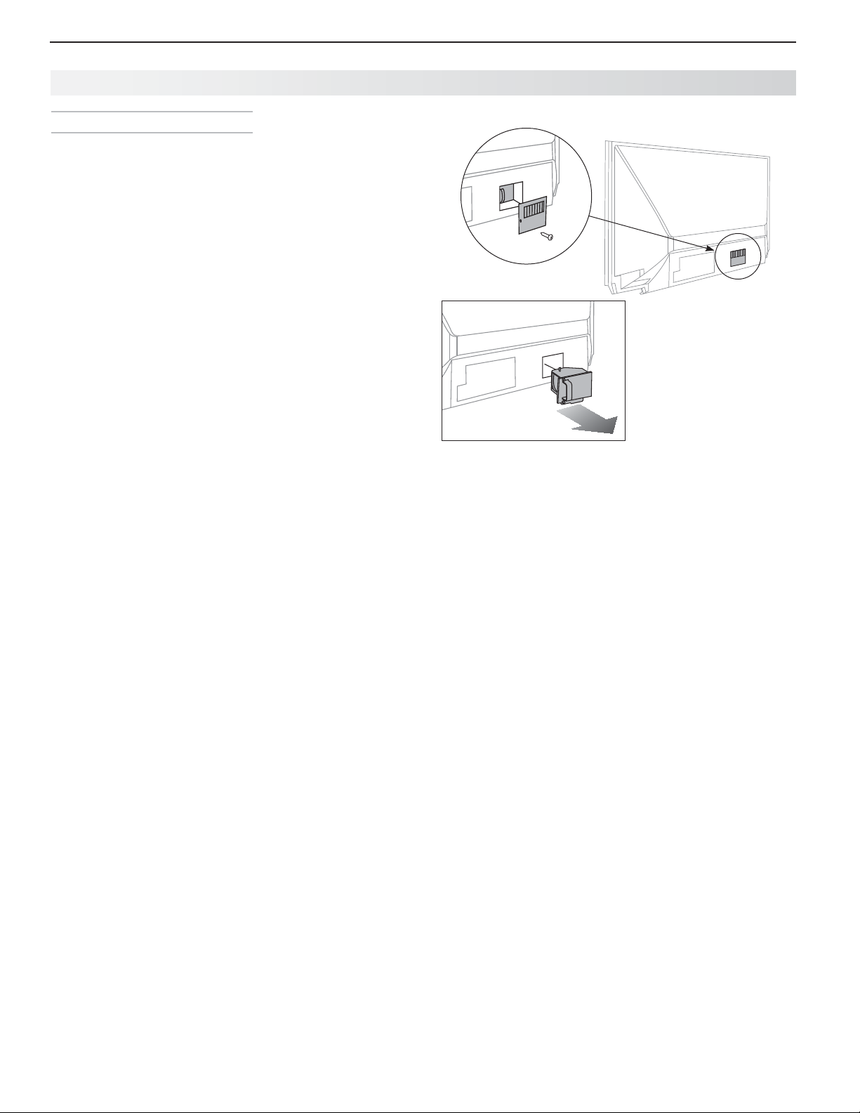
28 Appendices
Appendix A: TV Care, continued
Lamp-Cartridge Replacement
Removing the Old Lamp Cartridge
Turn off TV power and unplug the TV. Allow the
1.
lamp to cool for at least one hour before proceeding.
After the lamp has cooled, remove the cover of the
2.
lamp compartment, located on the back of the TV.
Refer to figures 1 and 2. Use a #2 (medium) Phillips
screwdriver to loosen the screw securing the cover.
Keep the screw and cover for re-installation
Wi
3.
th a medium Phillips screwdriver, loosen the two
screws securing the lamp cartridge until they disengage from the mating threads. These are captive
screws and cannot be separated from the lamp
cartridge.
Fully open the bag supplied with the replacement
4.
lamp and set the opened bag aside.
Gently grasp the handle of the lamp cartridge and
5.
pull the old cartridge straight out. See figure 3.
CAUTION: Do not tilt or rotate the cartridge, as
small glass fragments may fall out.
Without tilting or putting down the lamp cartridge,
6.
insert it into the opened bag. Close the bag while
being careful not to let any glass particles fall out.
Installing the New Lamp Cartridge
Do not touch the glass parts of the new lamp car-
1.
tridge. Insert the new cartridge into the TV in the
same orientation as the old cartridge. Push on the
cartridge housing until it is fully seated.
Gently tighten the screws with the screwdriver.
2.
AVOID OVERTIGHTENING!
Replace the plastic cover and retaining screws.
3.
WASH YOUR HANDS THOROUGHLY, AS THIS
4.
LAMP CONTAINS MERCURY.
Figure 2
Figure 3
Use only replacement lamp part number
915B441001.
Disposal of the Old Lamp Cartridge
Lamp under warranty: All lamps replaced under warranty must be returned to Mitsubishi. Use the return
shipping label provided and send to Mitsubishi Digital
Electronics, America, 625 Braselton Parkway, Suite 200,
Braselton, GA 30517.
IMPORTANT: Lamps found without defects will be
returned and charged back to the sender.
Lamp no longer under warranty:
local authorities or the Electronic Industries Alliance at
www.eiae.org for lamp-disposal or recycling instructions.
Do not dispose of the old lamp with common trash.
Contact your
Figure 1
For assistance call 1(800) 332-2119
Page 29

Appendices 29
Appendix A: TV Care, continued
Cl eaning Recommendations
Normally, light dusting with a dry, non-scratching duster
will keep your TV clean. If cleaning beyond this is
needed, please use the following guidelines:
First, turn off the TV and unplug the power cord from the
power outlet.
Occasionally clean dust build-up from the air-intake
grilles on the back and sides of the TV. Clean using a
vacuum cleaner with a brush attachment.
Top and Sides of the TV
Gently wipe down your TV with a soft, non-abrasive •
cloth such as cotton flannel, microfiber, or a clean
cloth diaper, lightly moistened with water. Dry with a
second dry, soft, non-abrasive cloth.
For oily dirt, add a few drops of mild liquid detergent, •
such as dishwashing detergent, to the water used
to moisten the cloth. Rinse with a second cloth
moistened only with water. Dry with a third dry, soft,
non-abrasive cloth.
Screen
Follow the instructions for the top and sides, wiping •
gently in an up and down motion.
Clean the entire screen evenly, not just sections of •
the screen.
Do not allow liquid to drip down the screen, as some •
liquid may enter the TV through the gap between the
screen and screen frame.
You may purchase Mitsubishi Screen Cleaner, part •
number CLEANER-VSS, by calling (800) 553-7278.
General Cleaning Precautions
DO NOT allow liquid to enter the TV through the •
ventilation slots or any crevice.
DO NOT use any strong or abrasive cleaners, as •
these can scratch the surfaces.
DO NOT use any cleaners containing ammonia, •
bleach, alcohol, benzene, or thinners, as these can
dull the surfaces.
DO NOT spray liquids or cleaners directly on the •
TV’s surfaces.
DO NOT scrub or rub the TV harshly. Wipe it gently.•
For assistance call 1(800) 332-2119
Page 30

30 Appendices
CAB/SAT DVD
TV
AUDIO
VCR
Appendix B: Programming the Remote Control
Programming the Remote Control
Change the control mode to match the device type.
1.
TV
CAB/SAT DVD
Mode Affected Device
CAB/SAT
VCR
DVD
AUDIO
Cable Box, DTV Receiver, Satellite Receiver
VCR, DVR, DVD Player/Recorder
DVD Player/Recorder, DVR, VCR
A/V Receiver, Audio Amplifier, CD Player
AUDIO
VCR
3.
4.
5.
6.
CABLE/SAT
VCR
Enter the first five-digit code listed for your equipment.
Point the remote control at the equipment and press
POWER
. If the product has no power on/off function,
press a different key, such as
VOLUME UP
, or
MUTE.
(
PLAY
), (
STOP
),
If the equipment does not respond, repeat the preceding two steps using the next five-digit code.
Once you have found the correct code, write it in the
space below for future reference.
Mode
Device Type Code
Press and hold
2.
POWER on the remote control for
several seconds until the key blinks twice and goes off
This is an abbreviated list showing
the most popular codes. For a full
list, see the detailed owner’s guide at
www.mitsubishi-tv.com.
Cable Boxes
General Instrument
Jerrold
Moto r o la 11376 , 11187, 1 047 6
Pac e 119 8 2, 11877, 113 76
Pioneer 11877, 10877
Scientific Atlanta 11877, 10877
10476
A/V Receivers
Bo se 419 33, 41841, 41629, 412 53,
41229, 406 39
Denon 42857, 42279
Harman/Kardon 42443, 42241, 41306, 41304,
40891
In te gra 4180 5, 41320, 412 98
JVC 42331, 42239, 42040,
4149 5, 41374
Ke nwood 41570, 4156 9, 41313
Mi tsubishi 41957, 419 22, 41921, 41920,
41393
Onk yo 41805, 415 31, 41320, 41298,
40842
Pa nas onic 41763, 4163 3, 415 48, 41518,
41316 , 4130 8, 41288, 41275,
42967, 42452, 42221, 41764
Pioneer 41935, 41384, 41023, 40630
So ny 41759, 41758, 41658 , 41622,
41558, 414 41, 41258, 41058,
42522, 42216, 42172, 41858,
41822
Tec hni cs 41518, 41308
Yam aha 41476, 41376, 41375, 41331,
41276, 41176, 40376, 40176
42471, 42467, 42061, 41815
For assistance call 1(800) 332-2119
DVD
.
AUDIO
Satellite Receivers
DirecTV 11749, 11377, 11142, 10749,
106 39, 10566, 10392, 10 247
118 5 6, 116 0 9, 11442, 11414,
1110 9 , 11076
Dish Network
System
Hughes Network
Systems
Mitsubishi 10749
RCA 10566, 10392, 10143
Samsu n g 11609, 114 4 2, 11377, 112 76,
10775, 11505, 11775
1174 9, 11442 , 11142, 10749
1110 9
VCRs
Hitachi 20042, 20000
JVC 20067
Magnavox 21593, 20593, 20081, 20039,
20035, 20000
Matsushita 20162, 20035
MGA 20043
Mitsubishi 20173, 20067, 20043
Panasonic 21062, 20616, 20614, 20162,
20035
RCA 20880, 20060, 20042
Sony 21972, 21032, 20636, 20035,
20033, 20032, 20000
Tivo 20739, 20636, 20618
Toshiba 21972, 21008, 20045, 20043
Zenith 21139, 20039, 20037, 20033,
20000
DVD Players
Apex Digital 31061, 31056, 31020, 31004,
30797, 30796, 30794, 30755,
30672
Coby 31628, 31351, 31177, 31165,
31107, 31086, 30852, 30778
Denon 32258, 30634, 30490
DVD Players
Funai 30675
Hitachi 30664, 30573
Insignia 32596, 32428, 32095, 30675
Integra 32147, 31769, 30627, 30571
JVC 32365, 31602, 31550, 31275,
31164, 30867, 30623, 30558
LG 31602, 30869, 30741, 30591
Magnavox 31506, 31472, 31354, 31177,
30675, 30646, 30539, 30503
Mitsubishi 31521, 30521
Onkyo 32147, 31769, 30627, 30503
Panasonic 31762, 31641, 31579, 30703,
30632, 30503, 30490
Philips 32084, 32056, 31340,,
31267, 30675, 30646, 30539,
30503, 32434, 31506, 31354
Pioneer 31571, 31512, 31460, 30632,
30631, 30571, 30525, 30142
32442
RCA 32213, 31769, 30822, 30790,
30571, 30522
Samsung 32069, 31470, 31075, 31044,
30820, 30573, 30490, 30199
32556, 32489, 32369, 32329
Sharp 32250, 31256, 30752, 30675,
30630
Sony 31633, 31536, 31516, 31431,
31070, 31033, 30864, 30533
Sylvania 30675
Tivo 31512, 31503
Yamaha 32558, 32298, 30817, 30646,
30545, 30539, 30490
Zenith 30869, 30741, 30591, 30503
Page 31

Appendices 31
Appendix C: Tr oub leshooting
TV Re set Comparison Guide
You can resolve many common TV problems using the
reset functions described in the following table. .
IMPORTANT
Before you change sound or picture settings: If
picture or sound settings seem wrong for a broadcast
channel (a channel from the
Reset Name When to Use How to Use Resulting Action
Format If the picture shape
seems incorrect, use
the
change the picture
shape.
PerfectColor™/
PerfecTint™
Reset (838
Series)
(for the single
input currently
being watched)
When the color
intensities seem out
of balance, use the
PerfectColor/PerfecTint
reset to reset the color
balances to the original
factory settings.
Both PerfectColor and
PerfecTint are reset at
the same time.
ANT
FORMAT
input, a cable box,
Press
picture shapes available for the
key to
signal.
FORMAT
While viewing the input to be 1.
reset, press
Picture > Perfect.
Press 2.
PerfectColor adjustment screen.
Press 3.
or satellite receiver), first check other channels from
the same input before changing settings. If most other
channels from the same input seem correct, there is
likely a problem with the broadcast rather than with the
TV. Use care in this case, as changes you make to fix
problems on individual channels also affect all other
channels on the same input.
to cycle through the
MENU
and go to
ENTER
to display the
CANCEL
to reset the colors.
The last-used format for a signal
type will be recalled on the input.
Note: Also check the aspect
ratio feature on your cable box or
satellite receiver as this may be
altering the picture.
All PerfectColor/PerfecTint
sliders are reset to the original
center position. The PefectColor/
PerfecTint settings for other
inputs remain unchanged.
A/V Memory
Reset
(for the single
current input)
When audio and/
or video settings for
a single input seem
incorrect, use A/V
Memory Reset to
return the input to
the original factory
settings.
While viewing the input to reset, 1.
press
Reset.
Press 2.
Press 3.
Service and Customer Support
Service
If you are unable to correct a problem with your TV,
consult your Mitsubishi dealer or Mitsubishi Consumer Relations at (800) 332-2119.
• DO NOT adjust any controls other than those
described in this Owner’s Guide.
• DO NOT remove the protective back cover of
your TV.
MENU
and go to Picture >
ENTER
to highlight Reset.
ENTER
again to reset.
Customer Support
• To order replacement or additional remote controls or lamp cart
mitsuparts.com or call (800) 553-7278.
• For questions:
Call Consumer Relations at 800-332-2119.
E-mail: MDEAservice@mdea.com
Website: www.mitsubishi-tv.com
Important
All lamps replaced under warranty must be returned
to Mitsubishi where they will be inspected to verify
failure defects.
All Audio and Video settings for
the individual input are reset
except for the global settings
for audio Balance, Listen To,
Language, Video Mute, Smooth
120.
ridges,
visit our website at www.
For assistance call 1(800) 332-2119
Page 32

32 Appendices
Appendix C: Troubleshooting, continued
Reset Name When to Use How to Use Resulting Action
A/V Reset
(for all inputs)
Channel
Memorization
Lock Menu
Pass Code
Control-Panel
Lock Release
System Reset If the TV does not turn
To reset audio and
video adjustments for
all inputs to the original
factory settings.
To erase and
re-memorize channels
on the
To change your Lock
menu pass code
To re-enable the
control-panel buttons
after activation of the
Control-Panel Lock
on or off, does not
respond to the remote
control or controlpanel buttons, or has
audio but no video.
ANT
input.
While viewing the TV, press the
control-panel buttons
VOLUME DOWN
least two seconds.
Press 1.
Channel.
Highlight the reception mode, 2.
e.g. Ant Air, and press
Highlight 3. All Channels and
press
Highlight 4. Scan.
Press 5.
memorization.
See the detailed owner’s guide at www.mitsubishi-tv.com for instructions.
Press and hold the
the control panel for ten seconds. If
the TV is powered off, you can now
press the
Press and hold the
the control panel for ten seconds.
at the same time for at
MENU
and go to Setup >
ENTER
ENTER
POWER
INPUT
and
ENTER
.
to start channel
INPUT
button on
button to turn it on.
POWER
button on
All Audio and Video settings are
returned to the original factory
settings, including global settings
not affected by Picture > Reset.
All previously memorized channels for the antenna input are
erased and a new set of memo-
.
rized channels is created. To
add or delete individual channels,
see the Setup > Channel > Edit
menu instructions on page 24 .
Allows the control panel to be
unlocked if the remote control is
misplaced.
The TV will turn off. Power on the
TV and the green LED will flash
quickly for about one minute. The
changes you made most recently,
before using
be lost.
SYSTEM RESET
, may
TV Reset
IMPORTANT:
Use this reset
only if other
troubleshooting
has been unsuccessful.
VUD U
Reset VUDU
Account Password
VUDU
Reset Parental
Controls Pass
code
To reset all consumeraccessible settings
and all memories to
the original factory
defaults.
Use TV Reset if the TV
can respond to controls but TV behavior is
abnormal.
CAUTION: All ownerperformed setups and
adjustments will be
erased.
You have forgotten
your account password.
You have forgotten
your pass code.
While viewing the TV, press 1.
MENU
to display the TV main
menu.
With the main menu displayed, 2.
press number keys 1 2 3 to
display the Reset menu.
READ THE ON-SCREEN 3.
WARNING AND INSTRUCTIONS.
If you do not wish to use this •
reset, press
back out.
If you wish to continue, •
press
memories and settings.
Using a computer, go to
www.VUDU.com.
Call VUDU Customer Care at
1-888-554-VUDU (8838).
ENTER
EXIT
or
MENU
to erase all
The TV will start the initialization
process and then turn off.
Power on the TV and the front
green LED will start flashing. All
memory and settings outlined in
this Owner’s Guide will need to
be set again.
to
Reset your account password
from the VUDU website (requires
access to e-mail).
VUDU Customer Care will reset
your pass code.
For assistance call 1(800) 332-2119
Page 33

Appendices 33
Appendix C: Troubleshooting, continued
Common Picture Problems
Symptom Remarks
1. Picture does not look like a high-defi-
nition picture.
2. TV has sound but no picture. Press •
3. Picture has become dimmer. • The lamp is nearing the end of its life. Order a new lamp.
4. A color program appears as a black
and white image, or the colors are
dim, or the screen is black.
5. Picture from an HDMI input is noisy
(poor quality).
Compare the picture to the TV’s test picture (Picture > Picture+ >
Test Picture) to check if the source signal is supplying a lesser-quality
image.
Not all signals are high-definition signals. To receive high-definition
programming from your cable or satellite provider, you must subscribe
to the provider’s high-definition service. Some over-the-air broadcasts
are in high-defi nition and can be received with a high-quality antenna
suited to your location.
MENU
on the remote control. If the menu displays, then there
is a problem with the incoming signal.
Check that all video inputs are plugged in firmly to the correct input •
jacks.
Press and hold the •
seconds to perform System Reset.
• Adjust picture brightness and contrast to maximum levels.
• Change Lamp Energy from Standard to Bright.
If using component video, check that the red, green, and blue input •
cables are correctly connected to the red, green, and blue component video jacks.
If using composite video, check that the incoming cable is con-•
nected the TV’s green
838 Series. The PerfectColor color balance has been incorrectly •
set. Reset the PerfectColor balance.
C• ompare the picture to the TV’s test picture (Picture > Picture+ >
Test Picture) to check if the noise is internal or external to the TV.
Upgrade a Category 1 (unmarked) HDMI cable to a newer type of •
high-speed HDMI cable.
POWER
button on the control panel for ten
Y/VID EO
jack.
Home Network
Symptom Remarks
1. I cannot connect the TV to the
network.
2. I plugged in a wireless USB adapter,
but the wireless connection is not
working.
3. The INTERNET key only goes to
VUDU.
Go to the Setup > Network menu. Obtain the TV MAC address and
provide it to the router.
The network may be locked. Go to Setup > Network. Highlight the
network name and supply the pass code.
Normal operation. The TV receives all internet services through VUDU.
The TV does not provide full internet access as does a web browser on
a computer.
For assistance call 1(800) 332-2119
Page 34

34 Trademark and License Information
Mitsubishi TV Software
END-USER LICENSE AGREEMENT FOR EMBEDDED SOFTWARE
IMPORTANT – READ CAREFULLY: This License Agreement is a legal agreement between you (either an individual or an entity) and
Mitsubishi Digital Electronics America, Inc. (MDEA) for all software pre installed and/or provided along with this television (“Software”). By
utilizing this television and Software, you agree to be bound by the terms of this License Agreement.
The Software is protected by United States copyright laws and international treaty provisions, as well as other intellectual property laws
and treaties. The Software is licensed, not sold.
1. LICENSE GRANT. MDEA grants you a non-exclusive, non-transferable, limited right and license to use one copy of the Software
only with the Mitsubishi television model that included this owner’s guide and owned by you.
2. RIGHTS AND LIMITATIONS.
Software Not for Resale. You may not resell or otherwise transfer for value the Software, except in conjunction with a sale of the TV that
Software has been pre installed.
Prohibition on Reverse Engineering, Decompilation and Disassembly. The Software contains trade secrets or other proprietary material
in its human perceivable form and to protect them, you may not reverse engineer, decompile, or disassemble, or otherwise reduce the
Software to any human perceivable form, except to the extent that the foregoing restriction is expressly prohibited by applicable law.
Separation of Components. The Software is licensed as a single product. Its component parts may not be separated for use on more
than one TV.
No Rental. You may not rent, lease, lend, or sublicense the Software.
Trademarks. This License Agreement does not grant you any rights to any trademarks of MDEA.
3. VIOLATIONS. You understand that any use, copying or transfer of the Software, except as permitted pursuant to this License,
may subject you to serious criminal and civil penalties including damages and an award to MDEA of attorneys’ fees in connection with any
violation of this License. You further understand that you may be held legally responsible for any copyright infringement or other violation
of intellectual property rights that is caused, encouraged, or induced by your failure to abide by the terms of the License. This license
is effective until terminated, and will terminate immediately without notice from MDEA or judicial resolution if you fail to comply with any
provision of this License.
4. COPYRIGHT. All title and intellectual property rights in and to the Software (including but not limited to any images, photographs,
animations, video, audio, music, text, and “applets” incorporated into the Software), and any accompanying printed materials are owned
by or licensed to MDEA. All title and intellectual property rights in and to the content which may be accessed through use of the Software
is the property of the respective content owner and may be protected by applicable copyright or other intellectual property laws and
treaties. This License Agreement grants you no rights to use such content, except that you own the media on which the Software is
recorded, but MDEA and its licensors retain ownership of the Software itself. All rights not expressly granted are reserved by MDEA.
5. EXPORT RESTRICTIONS. MDEA is licensing the Software for use within the United States. You agree that you will not
export or re-export the Software. You specifically agree not to export or re-export the Software: (i) to any country to which the U.S. has
embargoed or restricted the export of goods or services, which currently include, but are not necessarily limited to Cuba, Iran, Iraq, Libya,
North Korea, Sudan, and Syria, or to any national of any such country, wherever located, who intends to transmit or transport the Software
back to such country; (ii) to any person or entity who you know or have reason to know will utilize the Software in the design, development,
or production of nuclear, chemical, or biological weapons; or (iii) to any person or entity who has been prohibited from participating in
U.S. export transactions by any federal agency of the U.S. government. You warrant and represent that neither the BXA nor any other U.S.
federal agency has suspended, revoked, or denied your export privileges.
6. DISCLAIMER OF WARRANTY. EXCEPT AS OTHERWISE PROVIDED IN THIS LICENSE OR IN THE LIMITED WARRANT Y
APPLICABLE TO THE TV, MDEA MAKES NO OTHER WARRANTIES OF ANY KIND WHATSOEVER REGARDING THE SOFTWARE
AND HEREBY EXPRESSLY DISCLAIMS ALL WARRANTIES OF ANY KIND WHATSOEVER, EXPRESS OR IMPLIED, WITH
RESPECT TO THE SOFTWARE. ALL IMPLIED WARRANTIES, INCLUDING, WITHOUT LIMITATION, THE IMPLIED WARRANTIES
OF MERCHANTABILITY AND FITNESS FOR A PARTICULAR PURPOSE ARE HEREBY EXPRESSLY DISCLAIMED BY MDEA . IN
NO EVENT SHALL MDEA BE LIABLE TO YOU OR ANY THIRD PARTIES, IN CONTRACT, IN TORT OR OTHERWISE, FOR ANY
DIRECT, INDIRECT, SPECIAL, INCIDENTAL OR CONSEQUENTIAL DAMAGES OF ANY KIND OR NATURE. BECAUSE SOME
JURISDICTIONS DO NOT ALLOW THE EXCLUSION OR LIMITATION OF IMPLIED WARRANTIES, THE ABOVE LIMITATION MAY
NOT APPLY TO YOU.
7. LIMITATION OF LIABILITY. MDEA SHALL NOT, UNDER ANY CIRCUMSTANCES BE LIABLE TO YOU OR ANY THIRD
PARTIES FOR ANY DAMAGES OF ANY NATURE, WHETHER INDIRECT, SPECIAL, INCIDENTAL, CONSEQUENTIAL OR
OTHERWISE, INCLUDING, BUT NOT LIMITED TO, ANY CLAIMS FOR LOST PROFITS, LOSS OF GOOD WILL OR EXPENDITURES
MADE OR COMMITTED FOR IN RELIANCE ON THE CONTINUATION OF THIS LICENSE. YOU AGREE THAT NEITHER MDEA’S
BREACH OF THIS LICENSE NOR ITS FAILURE TO REPAIR A DEFECT, ERROR OR BUG SHALL CONSTITUTE A FAILURE OF THE
ESSENTIAL PURPOSE OF THIS LICENSE. BECAUSE SOME JURISDICTIONS DO NOT ALLOW THE EXCLUSION OR LIMITATION
OF LIABILITY FOR CONSEQUENTIAL OR INCIDENTAL DAMAGES, THE ABOVE LIMITATIONS MAY NOT APPLY TO YOU. MDEA’s
liability to you for direct damages for any cause whatsoever and regardless of the form of the action, will be limited to the money
paid by you for the TV (based on fair market value of the TV ) that caused the damages.
8. GENERAL. This License Agreement will be governed by the laws of the State of California.
WARNING: This product contains chemicals known to the State of California to cause cancer and/or birth defects
or other reproductive harm.
For assistance call 1(800) 332-2119
Page 35

Trademark and License Information 35
GNU General Public License
Version 2, June 1991
Copyright (C) 1989, 1991 Free Software Foundation, Inc.
675 Mass Ave, Cambridge, MA 02139, USA
Everyone is permitted to copy and distribute verbatim copies of this license document, but changing it is not allowed.
The licenses for most software are designed to take away your freedom to s
change free software--to make sure the software is free for all its users. This General Public License applies to most of the Free Software Foundation’s software and to any other program whose author s
commit to using it. (Some other Free Sof tware Foundation software is covered by the GNU Library General Public License instead.) You can apply it to your programs, too.
When we speak of free software, we are referring to freedom, not price. Our General Public Licenses are designed to make sure that you have the freedom to distribute copies of free software (and charge for
this ser vice if you wish), that you receive source code or can get it if you want it, that you can change the software or use pieces of it in new free programs; and that you know you can do these things.
To protect your rights, we need to make restrictions that forbid anyone to deny you these rights or to ask you to surrender the rights. These restrictions translate to certain responsibilities for you if you
distribute copies of the software, or if you modif y it.
For example, if you distribute copies of such a program, whether gratis or for a fee, you must give the recipients all the rights that you have. You must make sure that they, too, receive or can get the source
code. And you must show them these terms so they know their rights.
We protect your rights with two steps: (1) copyright the soft ware, and (2) offer you this license which gives you legal permission to copy, distribute and/or modify the software.
Also, for each author’s protection and ours, we want to make certain that everyone understands that there is no warranty for this free software. If the sof tware is modified by someone else and passed on, we
want its recipients to know that what they have is not the original, so that any problems introduced by others will not reflect on the original authors’ reputations.
Finally, any free program is threatened constantly by software patents. We wish to avoid the danger that redistributor s of a free program will individually obtain patent licenses, in effect making the program
proprietary. To prevent this, we have made it clear that any patent must be licensed for everyone’s free use or not licensed at all.
The precise terms and conditions for copying, distribution and modifi cation follow.
0. This License applies to any program or other work which contains a notice placed by the copyright holder saying it may be distributed under the terms of this General Public License. The “Program”,
below, refers to any such program or work, and a “work based on the Program” means either the Program or any derivative work under copyright law: that is to say, a work containing the Program or a portion
of it, either verbatim or with modifications and/or translated into another language. (Hereinafter, translation is included without limitation in the term “modification”.) Each licensee is addressed as “you”.
Activities other than copying, distribution and modification are not covered by this License; they are outside its scope. The act of running the Program is not restricted, and the output from the Program is
covered only if its contents constitute a work based on the Program (independent of having been made by running the Program). Whether that is true depends on what the Program does.
1. You may copy and distribute verbatim copies of the Program’s source code as you receive it, in any medium, provided that you conspicuously and appropriately publish on each copy an appropriate
copyright notice and disclaimer of warranty; keep intact all the notices that refer to this License and to the absence of any warranty; and give any other recipients of the Program a copy of this License along
with the Program.
You may charge a fee for the physical act of transferring a copy, and you may at your option offer warranty protection in exchange for a fee.
2. You may modify your copy or copies of the Program or any portion of it, thus forming a work based on the Program, and copy and distribute such modifications or work under the terms of Section 1 above,
provided that you also meet all of these conditions:
a) You must cause the modifie d files to carry prominent notices stating that you change d the files and the date of any change.
b) You must cause any work that you distribute or publish, that in whole or in part contains or is derived from the Program or any part thereof, to be licensed as a whole at no charge to all third parties
under the terms of this License.
c) If the modified program normally reads commands interactively when run, you must cause it, when started running for such interactive use in the most ordinary way, to print or display an
announcement including an appropriate copyright notice and a notice that there is no warranty (or else, saying that you provide a warranty) and that users may redistribute the program under these
conditions, and telling the user how to view a copy of this License. (Exception: if the Program itself is interactive but does not normally print such an announcement, your work based on the Program
is not required to print an announcement.)
These requirements apply to the modified work as a whole. If identifiable sections of that work are not derived from the Program, and can be reasonably considered independent and separate works in themselves, then this License, and its terms, do not apply to those sections when you distribute them as separate works. But when you distribute the same sections as part of a whole which is a work based on
the Program, the distribution of the whole must be on the terms of this License, whose permissions for other licensees extend to the entire whole, and thus to each and every part regardless of who wrote it.
Thus, it is not the intent of this section to claim rights or contest your rights to work written entirely by you; rather, the intent is to exercise the right to control the distribution of derivative or collective works
based on the Program.
In addition, mere aggregation of another work not based on the Program with the Program (or with a work based on the Program) on a volume of a storage or distribution medium does not bring the other
work under the scope of this License.
3. You may copy and distribute the Program (or a work based on it, under Section 2) in object code or executable form under the terms of Sections 1 and 2 above provided that you also do one of the following:
a) Accompany it with the complete corresponding machine-readable source code, which must be distributed under the terms of Sections 1 and 2 above on a medium customarily used for sof tware
interchange; or,
b) Accompany it with a written offer, valid for at least three years, to give any third party, for a charge no more than your cost of physically performing source distribution, a complete machine-readable
copy of the corresponding source code, to be distributed under the terms of Sections 1 and 2 above on a medium customarily used for software interchange; or,
c) Accompany it with the information you received as to the offer to distribute corresponding source code. (This alternative is allowed only for noncommercial distribution and only if you received the
program in object code or executable form with such an offer, in accord with Subsection b above.)
The source code for a work means the preferred form of the work for making modifications to it. For an executable work, complete source code means all the source code for all modules it contains, plus any
associated inter face definition files, plus the scripts used to control compilation and installation of the executable. However, as a special exception, the source code distributed need not include anything that
is normally distributed (in either source or binary form) with the major components (compiler, kernel, and so on) of the operating system on which the executable runs, unless that component itself accompanies the executable.
If distribution of executable or object code is made by offering access to copy from a designated place, then offering equivalent access to copy the source code from the same place counts as distribution of
the source code, even though third parties are not compelled to copy the source along with the object code.
4. You may not copy, modify, sublicense, or distribute the Program except as expressly provided under this License. Any attempt otherwise to copy, modify, sublicense or distribute the Program is void, and
will automatically terminate your rights under this License. However, parties who have received copies, or rights, from you under this License will not have their licenses terminated so long as such parties
remain in full compliance.
5. You are not required to accept this License, since you have not signed it. However, nothing else grants you permission to
prohibited by law if you do not accept this License. Therefore, by modifying or distributing the Program (or any work based on the Program), you indicate your acceptance of this License to do so, and all its
terms and conditions for copying, distributing or modifying the Program or works based on it.
6. Each time you redistribute the Program (or any work based on the Program), the recipient automatically receives a license from the original licensor to copy, distribute or modify the Program subject to
these terms and conditions. You may not impose any fur ther restrictions on the recipients’ exercise of the rights granted herein. You are not responsible for enforcing compliance by third parties to this
License.
7. If, as a consequence of a court judgment or allegation of patent infringement or for any other reason (not limited to patent is sues), conditions are imposed on you (whether by cour t order, agreement or
otherwise) that contradict the conditions of this License, they do not excuse you from the conditions of this License. If you cannot distribute so as to satisf y simultaneously your obligations under this License
and any other pertinent obligations, then as a consequence you may not distribute the Program at all. For example, if a patent license would not permit royalty-free redistribution of the Program by all those
who receive copies directly or indirectly through you, then the only way you could satisfy both it and this License would be to refrain entirely from distribution of the Program.
If any por tion of this section is held invalid or unenforceable under any particular circumstance, the balance of the section is intended to apply and the section as a whole is intended to apply in othe r circumstances.
It is not the purpose of this section to induce you to infringe any patents or other property right claims or to contest validity of any such claims; this section has the sole purpose of protecting the integrity of
the free software distribution system, which is implemented by public license practices. Many people have made generous contributions to the wide range of software distributed through that system in reliance on consistent application of that system; it is up to the author/donor to decide if he or she is willing to distribute software through any other system and a licensee cannot impose that choice.
This section is intended to make thoroughly clear what is believed to be a consequence of the rest of this License.
8. If the distribution and/or use of the Program is restricted in certain countries either by patents or by copyrighted inter faces, the original copyright holder who places the Program under this License may
add an explicit geographical distribution limitation excluding those countries, so that distribution is permit ted only in or among countries not thus excluded. In such case, this License incorporates the limitation as if written in the body of this License.
9. The Free Software Foundation may publish revised and/or new versions of the General Public License from time to time. Such new versions will be similar in spirit to the present version, but may differ in
detail to address new problems or concerns.
Each version is given a distinguishing version number. If the Program specifies a version number of this License which applies to it and “any later version”, you have the option of following the terms and conditions either of that version or of any later version published by the Free Software Foundation. If the Program does not specif y a version number of this License, you may choose any version ever published
by the Free Sof tware Foundation.
TERMS AND CONDITIONS FOR COPYING , DISTRIBUTION AND MODIFICATION
hare and change it. By contrast, the GNU General Public License is intended to guarantee your freedom to share and
GNU GENERAL PUBLIC LICENSE
Preamble
modify or distribute the Program or its derivative works. These actions are
If you are interested in obtaining open source code for this product, please contact Mitsubishi at
(800) 332-2119. A nominal handling and mailing charge may apply.
For assistance call 1(800) 332-2119
Page 36

36 Trademark and License Information
10. If you wish to incorporate parts of the Program into other free programs whose distribution conditions are dif ferent, write to the author to ask for permission. For software which is copyrighted by the
Free Software Foundation, write to the Free Software Foundation; we sometimes make exceptions for this. Our decision will be guided by the two goals of preserving the free status of all derivatives of our
free sof tware and of promoting the sharing and reuse of sof tware generally.
11. BECAUSE THE PROGRAM IS LICENSED FREE OF CHARGE, THERE IS NO WARRANTY FOR THE PROGRAM, TO THE EXTENT PERMITTED BY APPLICABLE L AW. EXCEPT WHEN OTHERWISE
STATED IN WRITING THE COPYRIGHT HOLDERS AND/OR OTHER PARTIES PROVIDE THE PROGRAM “AS IS” WITHOUT WARRANT Y OF ANY KIND, EITHER EXPRESSED OR IMPLIED, INCLUDING, BUT
NOT LIMITED TO, THE IMPLIED WARRANTIES OF MERCHANTABILITY AND FITNESS FOR A PARTICULAR PURPOSE. THE ENTIRE RISK AS TO THE QUALITY AND PERFORMANCE OF THE PROGRAM IS
WITH YOU. SHOULD THE PROGR AM PROVE DEFECTIVE, YOU ASSUME THE COST OF ALL NECESSARY SERVICING, REPAIR OR CORRECTION.
12. IN NO EVENT UNLESS REQUIRED BY APPLICABLE L AW OR AGREED TO IN WRITING WILL ANY COPYRIGHT HOLDER, OR ANY OTHER PART Y WHO MAY MODIFY AND/OR REDISTRIBUTE THE
PROGRAM AS PERMITTED ABOVE, BE LIABLE TO YOU FOR DAMAGES, INCLUDING ANY GENERAL, SPECIAL, INCIDENTAL OR CONSEQUENTIAL DAMAGES ARISING OUT OF THE USE OR INABILITY
TO USE THE PROGRAM (INCLUDING BUT NOT LIMITED TO LOSS OF DATA OR DATA BEING RENDERED INACCURATE OR LOSSES SUSTAINED BY YOU OR THIRD PARTIES OR A FAILURE OF THE
PROGRAM TO OPERATE WITH ANY OTHER PROGR AMS), EVEN IF SUCH HOLDER OR OTHER PARTY HAS BEEN ADVISED OF THE POSSIBILITY OF SUCH DAMAGES.
NO WARRANTY
GNU GENERAL PUBLIC LICENSE
Version 3, 29 June 2007
Copyright © 2007 Free Software Foundation, Inc. <http://fsf.org/>
Everyone is permitted to copy and distribute verbatim copies of this license document, but changing it is not allowed.
Preamble
The GNU General Public License is a free, copyleft license for software and other kinds of works.
The licenses for most software and other practical works are designed to take away your freedom to share and change the works. By contrast, the GNU General Public License is intended to guarantee your freedom to share
and change all versions of a program--to make sure it remains free software for all its users. We, the Free Software Foundation, use the GNU General Public License for most of our software; it applies also to any other work
released this way by its authors. You can apply it to your programs, too.
When we speak of free software, we are referring to freedom, not price. Our General Public Licenses are designed to make sure that you have the freedom to distribute copies of free software (and charge for them if you wish),
that you receive source code or can get it if you want it, that you can change the software or use pieces of it in new free programs, and that you know you can do these things.
To protect your rights, we need to prevent others from denying you these rights or asking you to surrender the rights. Therefore, you have certain responsibilities if you distribute copies of the software, or if you modify it:
responsibilities to respect the freedom of others.
For example, if you distribute copies of such a program, whether gratis or for a fee, you must pass on to the recipients the same freedoms that you received. You must make sure that they, too, receive or can get the source
code. And you must show them these terms so they know their rights.
Developers that use the GNU GPL protect your rights with two steps: (1) assert copyright on the software, and (2) offer you this License giving you legal permission to copy, distribute and/or modify it.
For the developers’ and authors’ protection, the GPL clearly explains that there is no warranty for this free software. For both users’ and authors’ sake, the GPL requires that modifi ed versions be marked as changed, so that
their problems will not be attributed erroneously to authors of previous versions.
Some devices are designed to deny users access to install or run modifi ed versions of the software inside them, although the manufacturer can do so. This is fundamentally incompatible with the aim of protecting users’ freedom to change the software. The systematic pattern of such abuse occurs in the area of products for individuals to use, which is precisely where it is most unacceptable. Therefore, we have designed this version of the GPL to
prohibit the practice for those products. If such problems arise substantially in other domains, we stand ready to extend this provision to those domains in future versions of the GPL, as needed to protect the freedom of users.
Finally, every program is threatened constantly by software patents. States should not allow patents to restrict development and use of software on general-purpose computers, but in those that do, we wish to avoid the special
danger that patents applied to a free program could make it effectively proprietary. To prevent this, the GPL assures that patents cannot be used to render the program non-free.
The precise terms and conditions for copying, distribution and modifi cation follow.
TERMS AND CONDITIONS
0. Defi nitions.
“This License” refers to version 3 of the GNU General Public License.
“Copyright” also means copyright-like laws that apply to other kinds of works, such as semiconductor masks.
“The Program” refers to any copyrightable work licensed under this License. Each licensee is addressed as “you”. “Licensees” and “recipients” may be individuals or organizations.
To “modify” a work means to copy from or adapt all or part of the work in a fashion requiring copyright permission, other than the making of an exact copy. The resulting work is called a “modifi ed version” of the earlier work or
a work “based on” the earlier work.
A “covered work” means either the unmodifi ed Program or a work based on the Program.
To “propagate” a work means to do anything with it that, without permission, would make you directly or secondarily liable for infringement under applicable copyright law, except executing it on a computer or modifying a
private copy. Propagation includes copying, distribution (with or without modifi cation), making available to the public, and in some countries other activities as well.
To “convey” a work means any kind of propagation that enables other parties to make or receive copies. Mere interaction with a user through a computer network, with no transfer of a copy, is not conveying.
An interactive user interface displays “Appropriate Legal Notices” to the extent that it includes a convenient and prominently visible feature that (1) displays an appropriate copyright notice, and (2) tells the user that there is
no warranty for the work (except to the extent that warranties are provided), that licensees may convey the work under this License, and how to view a copy of this License. If the interface presents a list of user commands or
options, such as a menu, a prominent item in the list meets this criterion.
1. Source Code.
The “source code” for a work means the preferred form of the work for making modifi cations to it. “Object code” means any non-source form of a work.
A “Standard Interface” means an interface that either is an offi cial standard defi ned by a recognized standards body, or, in the case of interfaces specifi ed for a particular programming language, one that is widely used among
developers working in that language.
The “System Libraries” of an executable work include anything, other than the work as a whole, that (a) is included in the normal form of packaging a Major Component, but which is not part of that Major Component, and (b)
serves only to enable use of the work with that Major Component, or to implement a Standard Interface for which an implementation is available to the public in source code form. A “Major Component”, in this context, means a
major essential component (kernel, window system, and so on) of the specifi c operating system (if any) on which the executable work runs, or a compiler used to produce the work, or an object code interpreter used to run it.
The “Corresponding Source” for a work in object code form means all the source code needed to generate, install, and (for an executable work) run the object code and to modify the work, including scripts to control those
activities. However, it does not include the work’s System Libraries, or general-purpose tools or generally available free programs which are used unmodifi ed in performing those activities but which are not part of the work. For
example, Corresponding Source includes interface defi nition fi les associated with source fi les for the work, and the source code for shared libraries and dynamically linked subprograms that the work is specifi cally designed to
require, such as by intimate data communication or control fl ow between those subprograms and other parts of the work.
The Corresponding Source need not include anything that users can regenerate automatically from other parts of the Corresponding Source.
The Corresponding Source for a work in source code form is that same work.
2. Basic Permissions.
All rights granted under this License are granted for the term of copyright on the Program, and are irrevocable provided the stated conditions are met. This License explicitly affi rms your unlimited permission to run the unmodifi ed Program. The output from running a covered work is covered by this License only if the output, given its content, constitutes a covered work. This License acknowledges your rights of fair use or other equivalent, as
provided by copyright law.
You may make, run and propagate covered works that you do not convey, without conditions so long as your license otherwise remains in force. You may convey covered works to others for the sole purpose of having them
make modifi cations exclusively for you, or provide you with facilities for running those works, provided that you comply with the terms of this License in conveying all material for which you do not control copyright. Those thus
making or running the covered works for you must do so exclusively on your behalf, under your direction and control, on terms that prohibit them from making any copies of your copyrighted material outside their relationship
with you.
Conveying under any other circumstances is permitted solely under the conditions stated below. Sublicensing is not allowed; section 10 makes it unnecessary.
3. Protecting Users’ Legal Rights From Anti-Circumvention Law.
No covered work shall be deemed part of an effective technological measure under any applicable law fulfi
or restricting circumvention of such measures.
When you convey a covered work, you waive any legal power to forbid circumvention of technological measures to the extent such circumvention is effected by exercising rights under this License with respect to the covered
work, and you disclaim any intention to limit operation or modifi cation of the work as a means of enforcing, against the work’s users, your or third parties’ legal rights to forbid circumvention of technological measures.
4. Conveying Verbatim Copies.
You may convey verbatim copies of the Program’s source code as you receive it, in any medium, provided that you conspicuously and appropriately publish on each copy an appropriate copyright notice; keep intact all notices
stating that this License and any non-permissive terms added in accord with section 7 apply to the code; keep intact all notices of the absence of any warranty; and give all recipients a copy of this License along with the
Program.
You may charge any price or no price for each copy that you convey, and you may offer support or warranty protection for a fee.
5. Conveying Modifi ed Source Versions.
You may convey a work based on the Program, or the modifi cations to produce it from the Program, in the form of source code under the terms of section 4, provided that you also meet all of these conditions:
a) The work must carry prominent notices stating that you modifi ed it, and giving a relevant date.
b) The work must carry prominent notices stating that it is released under this License and any conditions added under section 7. This requirement modifi es the requirement in section 4 to “keep intact all notices”.
c) You must license the entire work, as a whole, under this License to anyone who comes into possession of a copy. This License will therefore apply, along with any applicable section 7 additional terms, to the whole of the
work, and all its parts, regardless of how they are packaged. This License gives no permission to license the work in any other way, but it does not invalidate such permission if you have separately received it.
d) If the work has interactive user interfaces, each must display Appropriate Legal Notices; however, if the Program has interactive interfaces that do not display Appropriate Legal Notices, your work need not make them do so.
A compilation of a covered work with other separate and independent works, which are not by their nature extensions of the covered work, and which are not combined with it such as to form a larger program, in or on a volume of a storage or distribution medium, is called an “aggregate” if the compilation and its resulting copyright are not used to limit the access or legal rights of the compilation’s users beyond what the individual works permit.
Inclusion of a covered work in an aggregate does not cause this License to apply to the other parts of the aggregate.
6. Conveying Non-Source Forms.
You may convey a covered work in object code form under the terms of sections 4 and 5, provided that you also convey the machine-readable Corresponding Source under the terms of this License, in one of these ways:
a) Convey the object code in, or embodied in, a physical product (including a physical distribution medium), accompanied by the Corresponding Source fi xed on a durable physical medium customarily used for software inter-
change.
b) Convey the object code in, or embodied in, a physical product (including a physical distribution medium), accompanied by a written offer, valid for at least three years and valid for as long as you offer spare parts or customer
support for that product model, to give anyone who possesses the object code either (1) a copy of the Corresponding Source for all the software in the product that is covered by this License, on a durable physical medium
customarily used for software interchange, for a price no more than your reasonable cost of physically performing this conveying of source, or (2) access to copy the Corresponding Source from a network server at no charge.
c) Convey individual copies of the object code with a copy of the written offer to provide the Corresponding Source. This alternative is allowed only occasionally and noncommercially, and only if you received the object code
with such an offer, in accord with subsection 6b.
d) Convey the object code by offering access from a designated place (gratis or for a charge), and offer equivalent access to the Corresponding Source in the same way through the same place at no further charge. You need
not require recipients to copy the Corresponding Source along with the object code. If the place to copy the object code is a network server, the Corresponding Source may be on a different server (operated by you or a third
party) that supports equivalent copying facilities, provided you maintain clear directions next to the object code saying where to fi nd the Corresponding Source. Regardless of what server hosts the Corresponding Source, you
remain obligated to ensure that it is available for as long as needed to satisfy these requirements.
lling obligations under article 11 of the WIPO copyright treaty adopted on 20 December 1996, or similar laws prohibiting
For assistance call 1(800) 332-2119
Page 37

Trademark and License Information 37
e) Convey the object code using peer-to-peer transmission, provided you inform other peers where the object code and Corresponding Source of the work are being offered to the general public at no charge under subsection
6d.
A separable portion of the object code, whose source code is excluded from the Corresponding Source as a System Library, need not be included in conveying the object code work.
A “User Product” is either (1) a “consumer product”, which means any tangible personal property which is normally used for personal, family, or household purposes, or (2) anything designed or sold for incorporation into a
dwelling. In determining whether a product is a consumer product, doubtful cases shall be resolved in favor of coverage. For a particular product received by a particular user, “normally used” refers to a typical or common
use of that class of product, regardless of the status of the particular user or of the way in which the particular user actually uses, or expects or is expected to use, the product. A product is a consumer product regardless of
whether the product has substantial commercial, industrial or non-consumer uses, unless such uses represent the only signifi cant mode of use of the product.
“Installation Information” for a User Product means any methods, procedures, authorization keys, or other information required to install and execute modifi ed versions of a covered work in that User Product from a modifi ed
version of its Corresponding Source. The information must suffi ce to ensure that the continued functioning of the modifi ed object code is in no case prevented or interfered with solely because modifi cation has been made.
If you convey an object code work under this section in, or with, or specifi cally for use in, a User Product, and the conveying occurs as part of a transaction in which the right of possession and use of the User Product is
transferred to the recipient in perpetuity or for a fi xed term (regardless of how the transaction is characterized), the Corresponding Source conveyed under this section must be accompanied by the Installation Information. But
this requirement does not apply if neither you nor any third party retains the ability to install modifi ed object code on the User Product (for example, the work has been installed in ROM).
The requirement to provide Installation Information does not include a requirement to continue to provide support service, warranty, or updates for a work that has been modifi ed or installed by the recipient, or for the User
Product in which it has been modifi ed or installed. Access to a network may be denied when the modifi cation itself materially and adversely affects the operation of the network or violates the rules and protocols for communication across the network.
Corresponding Source conveyed, and Installation Information provided, in accord with this section must be in a format that is publicly documented (and with an implementation available to the public in source code form), and
must require no special password or key for unpacking, reading or copying.
7. Additional Terms.
“Additional permissions” are terms that supplement the terms of this License by making exceptions from one or more of its conditions. Additional permissions that are applicable to the entire Program shall be treated as though
they were included in this License, to the extent that they are valid under applicable law. If additional permissions apply only to part of the Program, that part may be used separately under those permissions, but the entire
Program remains governed by this License without regard to the additional permissions.
When you convey a copy of a covered work, you may at your option remove any additional permissions from that copy, or from any part of it. (Additional permissions may be written to require their own removal in certain cases
when you modify the work.) You may place additional permissions on material, added by you to a covered work, for which you have or can give appropriate copyright permission.
Notwithstanding any other provision of this License, for material you add to a covered work, you may (if authorized by the copyright holders of that material) supplement the terms of this License with terms:
a) Disclaiming warranty or limiting liability differently from the terms of sections 15 and 16 of this License; or
b) Requiring preservation of specifi ed reasonable legal notices or author attributions in that material or in the Appropriate Legal Notices displayed by works containing it; or
c) Prohibiting misrepresentation of the origin of that material, or requiring that modifi ed versions of such material be marked in reasonable ways as different from the original version; or
d) Limiting the use for publicity purposes of names of licensors or authors of the material; or
e) Declining to grant rights under trademark law for use of some trade names, trademarks, or service marks; or
f) Requiring indemnifi cation of licensors and authors of that material by anyone who conveys the material (or modifi ed versions of it) with contractual assumptions of liability to the recipient, for any liability that these contractual
assumptions directly impose on those licensors and authors.
All other non-permissive additional terms are considered “further restrictions” within the meaning of section 10. If the Program as you received it, or any part of it, contains a notice stating that it is governed by this License
along with a term that is a further restriction, you may remove that term. If a license document contains a further restriction but permits relicensing or conveying under this License, you may add to a covered work material
governed by the terms of that license document, provided that the further restriction does not survive such relicensing or conveying.
If you add terms to a covered work in accord with this section, you must place, in the relevant source fi les, a statement of the additional terms that apply to those fi les, or a notice indicating where to fi nd the applicable terms.
Additional terms, permissive or non-permissive, may be stated in the form of a separately written license, or stated as exceptions; the above requirements apply either way.
8. Termination.
You may not propagate or modify a covered work except as expressly provided under this License. Any attempt otherwise to propagate or modify it is void, and will automatically terminate your rights under this License (including any patent licenses granted under the third paragraph of section 11).
However, if you cease all violation of this License, then your license from a particular copyright holder is reinstated (a) provisionally, unless and until the copyright holder explicitly and fi nally terminates your license, and (b)
permanently, if the copyright holder fails to notify you of the violation by some reasonable means prior to 60 days after the cessation.
Moreover, your license from a particular copyright holder is reinstated permanently if the copyright holder notifi es you of the violation by some reasonable means, this is the fi rst time you have received notice of violation of this
License (for any work) from that copyright holder, and you cure the violation prior to 30 days after your receipt of the notice.
Termination of your rights under this section does not terminate the licenses of parties who have received copies or rights from you under this License. If your rights have been terminated and not permanently reinstated, you do
not qualify to receive new licenses for the same material under section 10.
9. Acceptance Not Required for Having Copies.
You are not required to accept this License in order to receive or run a copy of the Program. Ancillary propagation of a covered work occurring solely as a consequence of using peer-to-peer transmission to receive a copy
likewise does not require acceptance. However, nothing other than this License grants you permission to propagate or modify any covered work. These actions infringe copyright if you do not accept this License. Therefore, by
modifying or propagating a covered work, you indicate your acceptance of this License to do so.
10. Automatic Licensing of Downstream Recipients.
Each time you convey a covered work, the recipient automatically receives a license from the original licensors, to run, modify and propagate that work, subject to this License. You are not responsible for enforcing compliance
by third parties with this License.
An “entity transaction” is a transaction transferring control of an organization, or substantially all assets of one, or subdividing an organization, or merging organizations. If propagation of a covered work results from an entity
transaction, each party to that transaction who receives a copy of the work also receives whatever licenses to the work the par
sion of the Corresponding Source of the work from the predecessor in interest, if the predecessor has it or can get it with reasonable efforts.
You may not impose any further restrictions on the exercise of the rights granted or affi rmed under this License. For example, you may not impose a license fee, royalty, or other charge for exercise of rights granted under this
License, and you may not initiate litigation (including a cross-claim or counterclaim in a lawsuit) alleging that any patent claim is infringed by making, using, selling, offering for sale, or importing the Program or any portion of it.
11. Patents.
A “contributor” is a copyright holder who authorizes use under this License of the Program or a work on which the Program is based. The work thus licensed is called the contributor’s “contributor version”.
A contributor’s “essential patent claims” are all patent claims owned or controlled by the contributor, whether already acquired or hereafter acquired, that would be infringed by some manner, permitted by this License, of making, using, or selling its contributor version, but do not include claims that would be infringed only as a consequence of further modifi cation of the contributor version. For purposes of this defi nition, “control” includes the right
to grant patent sublicenses in a manner consistent with the requirements of this License.
Each contributor grants you a non-exclusive, worldwide, royalty-free patent license under the contributor’s essential patent claims, to make, use, sell, offer for sale, import and otherwise run, modify and propagate the contents
of its contributor version.
In the following three paragraphs, a “patent license” is any express agreement or commitment, however denominated, not to enforce a patent (such as an express permission to practice a patent or covenant not to sue for patent infringement). To “grant” such a patent license to a party means to make such an agreement or commitment not to enforce a patent against the party.
If you convey a covered work, knowingly relying on a patent license, and the Corresponding Source of the work is not available for anyone to copy, free of charge and under the terms of this License, through a publicly available
network server or other readily accessible means, then you must either (1) cause the Corresponding Source to be so available, or (2) arrange to deprive yourself of the benefi t of the patent license for this particular work, or (3)
arrange, in a manner consistent with the requirements of this License, to extend the patent license to downstream recipients. “Knowingly relying” means you have actual knowledge that, but for the patent license, your conveying the covered work in a country, or your recipient’s use of the covered work in a country, would infringe one or more identifi able patents in that country that you have reason to believe are valid.
If, pursuant to or in connection with a single transaction or arrangement, you convey, or propagate by procuring conveyance of, a covered work, and grant a patent license to some of the parties receiving the covered work
authorizing them to use, propagate, modify or convey a specifi c copy of the covered work, then the patent license you grant is automatically extended to all recipients of the covered work and works based on it.
A patent license is “discriminatory” if it does not include within the scope of its coverage, prohibits the exercise of, or is conditioned on the non-exercise of one or more of the rights that are specifi cally granted under this
License. You may not convey a covered work if you are a party to an arrangement with a third party that is in the business of distributing software, under which you make payment to the third party based on the extent of
your activity of conveying the work, and under which the third party grants, to any of the parties who would receive the covered work from you, a discriminatory patent license (a) in connection with copies of the covered work
conveyed by you (or copies made from those copies), or (b) primarily for and in connection with specifi c products or compilations that contain the covered work, unless you entered into that arrangement, or that patent license
was granted, prior to 28 March 2007.
Nothing in this License shall be construed as excluding or limiting any implied license or other defenses to infringement that may otherwise be available to you under applicable patent law.
12. No Surrender of Others’ Freedom.
If conditions are imposed on you (whether by court order, agreement or otherwise) that contradict the conditions of this License, they do not excuse you from the conditions of this License. If you cannot convey a covered work
so as to satisfy simultaneously your obligations under this License and any other pertinent obligations, then as a consequence you may not convey it at all. For example, if you agree to terms that obligate you to collect a royalty
for further conveying from those to whom you convey the Program, the only way you could satisfy both those terms and this License would be to refrain entirely from conveying the Program.
13. Use with the GNU Affero General Public License.
Notwithstanding any other provision of this License, you have permission to link or combine any covered work with a work licensed under version 3 of the GNU Affero General Public License into a single combined work, and
to convey the resulting work. The terms of this License will continue to apply to the part which is the covered work, but the special requirements of the GNU Affero General Public License, section 13, concerning interaction
through a network will apply to the combination as such.
14. Revised Versions of this License.
The Free Software Foundation may publish revised and/or new versions of the GNU General Public License from time to time. Such new versions will be similar in spirit to the present version, but may differ in detail to address
new problems or concerns.
Each version is given a distinguishing version number. If the Program specifi es that a certain numbered version of the GNU General Public License “or any later version” applies to it, you have the option of following the terms
and conditions either of that numbered version or of any later version published by the Free Software Foundation. If the Program does not specify a version number of the GNU General Public License, you may choose any
version ever published by the Free Software Foundation.
If the Program specifi es that a proxy can decide which future versions of the GNU General Public License can be used, that proxy’s public statement of acceptance of a version permanently authorizes you to choose that version for the Program.
Later license versions may give you additional or different permissions. However, no additional obligations are imposed on any author or copyright holder as a result of your choosing to follow a later version.
15. Disclaimer of Warranty.
THERE IS NO WARRANTY FOR THE PROGRAM, TO THE EXTENT PERMITTED BY APPLICABLE LAW. EXCEPT WHEN OTHERWISE STATED IN WRITING THE COPYRIGHT HOLDERS AND/OR OTHER PARTIES PROVIDE
THE PROGRAM “AS IS” WITHOUT WARRANTY OF ANY KIND, EITHER EXPRESSED OR IMPLIED, INCLUDING, BUT NOT LIMITED TO, THE IMPLIED WARRANTIES OF MERCHANTABILITY AND FITNESS FOR A PARTICULAR PURPOSE. THE ENTIRE RISK AS TO THE QUALITY AND PERFORMANCE OF THE PROGRAM IS WITH YOU. SHOULD THE PROGRAM PROVE DEFECTIVE, YOU ASSUME THE COST OF ALL NECESSARY SERVICING,
REPAIR OR CORRECTION.
16. Limitation of Liability.
IN NO EVENT UNLESS REQUIRED BY APPLICABLE LAW OR AGREED TO IN WRITING WILL ANY COPYRIGHT HOLDER, OR ANY OTHER PARTY WHO MODIFIES AND/OR CONVEYS THE PROGRAM AS PERMITTED
ABOVE, BE LIABLE TO YOU FOR DAMAGES, INCLUDING ANY GENERAL, SPECIAL, INCIDENTAL OR CONSEQUENTIAL DAMAGES ARISING OUT OF THE USE OR INABILITY TO USE THE PROGRAM (INCLUDING BUT
NOT LIMITED TO LOSS OF DATA OR DATA BEING RENDERED INACCURATE OR LOSSES SUSTAINED BY YOU OR THIRD PARTIES OR A FAILURE OF THE PROGRAM TO OPERATE WITH ANY OTHER PROGRAMS), EVEN
IF SUCH HOLDER OR OTHER PARTY HAS BEEN ADVISED OF THE POSSIBILITY OF SUCH DAMAGES.
17. Interpretation of Sections 15 and 16.
If the disclaimer of warranty and limitation of liability provided above cannot be given local legal effect according to their terms, reviewing courts shall apply local law that most closely approximates an absolute waiver of all civil
liability in connection with the Program, unless a warranty or assumption of liability accompanies a copy of the Program in return for a fee.
ty’s predecessor in interest had or could give under the previous paragraph, plus a right to posses-
For assistance call 1(800) 332-2119
Page 38

38 Warranty
Mi tsubishi Home-Cinema Television Limited Warranty
MITSUBISHI DIGITAL ELECTRONICS AMERICA, INC. (“MDEA”) warrants as follows to the original purchaser of this
television from an authorized MITSUBISHI Audio/Video Dealer, should it prove defective by reason of against defects
arising from improper workmanship and/or material:
a. Parts. The lenticular (i.e. front picture) screen is warranted against defects in materials and workmanship for a
period of thirty (30) days from the date of the original purchase at retail. The lamp and all other parts (except any software incorporated into this television) are warranted for a period of one (1) year from the date of the original purchase
at retail. We will repair or replace, at our option, any defective part without charge for the part. Parts used for replacement may be replaced with those of like kind and quality and may be new or remanufactured. Parts used for replacement are warranted for the remainder of the original warranty period.
b. Embedded Software. MDEA warrants that all software incorporated into this television set (the “Embedded
Software”) will perform in accordance with the functional description of Embedded Software in all material respects,
but MDEA does not warrant that the Embedded Software is error-free. The limited warranty contained in this section
shall continue for a period of one (1) year from the date of the original purchase at retail. If, after prompt notice within
the warranty period, MDEA determines that the Embedded Software has failed to perform in accordance with such
functional description in all material respects and if such failure is not due to accident, misuse, modification or misapplication of the Embedded Software, then MDEA shall modify or replace the nonconforming Embedded Software at
no charge to you, which at MDEA’s sole discretion may be fulfilled by means of modification or replacement software
contained on a replacement memory card for Customer installation. The foregoing shall be MDEA’s sole obligation
to you under this limited warranty. All rights under this limited warranty on the Embedded Software also subject to
your acceptance of and compliance with the terms of the Software License Agreement applicable to this television,
and this limited warranty on the Embedded Software shall be null and void if the Embedded Software is modified or
changed in any manner except as specifically authorized by MDEA.
c. Labor. For thirty (30) days after the original purchase at retail, we will repair or replace, at our option, the lenticular screen if it proves defective. For certain items that are designed to be replaced by the consumer, including (but
not limited to) some Embedded Software, the consumer is solely responsible for any replacement labor. For all other
parts, we will provide the labor for a warranty repair by an authorized MITSUBISHI service center without charge for
one (1) year from the original date of purchase at retail.
d. Notice. To obtain warranty service, you must notify an authorized MITSUBISHI service center of any defect within
the applicable warranty time period.
e. This DLP Projection Television uses a single DLP chip to create the screen image. This technology creates the
image using small dots, or picture elements (pixels). Your DLP Projection TV is manufactured to a high level of performance and quality, in fact, 99.99% perfect in the number of properly functioning pixels. As in other display technology, sometimes a pixel is continuously active, inactive or the incorrect color. Our standard is clear; MDEA warrants
only that the percentage of properly functioning pixels will be not less than 99.99% of all pixels.
BEFORE REQUESTING SERVICE, please review the instruction booklet to insure proper installation and
correct customer control adjustment. If the problem persists please arrange for warranty service.
1. TO OBTAIN WARRANTY SERVICE:
a. Contact your nearest authorized MITSUBISHI service center, whose name and address can be obtained from your
MITSUBISHI dealer, by writing at the address provided below, calling MDEA at the 800-332-2119, or by using the
support feature of our website at www.Mitsubishi-tv.com.
b. Warranty service will be provided in your home or, if required, at an authorized service shop, provided that your
television is located within the geographic territory customarily covered by an authorized MITSUBISHI service center.
If not, you must either deliver your television to an authorized service location at your own expense, or pay for any
travel and/or transportation costs the service center may charge to and from your home. Actual service labor will be
provided without charge.
c. Proof of purchase date from an authorized MITSUBISHI dealer is required when requesting warranty service.
Present your sales receipt or other document which establishes proof and date of purchase. THE RETURN OF THE
OWNER REGISTRATION CARD IS NOT A CONDITION OF COVERAGE UNDER THIS LIMITED WARRANTY. However,
please return the Owner Registration Card so that we can contact you should a question of safety arise which could
affect you.
For assistance call 1(800) 332-2119
Page 39

Warranty 39
d. To obtain a replacement lamp, order the lamp directly from the MDEA Parts Department at (800) 553-7278.
2. THIS LIMITED WARRANTY DOES NOT COVER:
a. Up to .01% pixel outages (small dot picture elements that are dark or incorrectly illuminated).
b. Damage to the lenticular screen or Fresnel lens, screen frame, cosmetic damage or to any other damage where
such damage is caused by unauthorized modification, alteration, repairs to or service of the product by anyone other
than an authorized MITSUBISHI service center; physical abuse to or misuse of the product (including any failure to
carry out any maintenance as described in the Owner’s Guide including air vent cleaning or any product damaged
by excessive physical or electrical stress); any products that have had a serial number or any part thereof altered,
defaced or removed; product use in any manner contrary to the Owner’s Guide; freight damage; or any damage
caused by acts of God or other factors beyond the reasonable control of MDEA, such as power surge damage
caused by electrical system or lightning. This limited warranty also excludes service calls where no defect in the
product covered under this warranty is found, service calls related to unsatisfactory audio or visual reception or signal
unless caused by a defect in the product that is covered under this limited warranty, all costs, expenses or any other
damages arising from product installation, or set-ups, any adjustments of user controls (including contrast, brightness, color, tint, fine tuning, sharpness), other adjustment necessary to prepare the unit for display or use, connection
with any external audio receiver, antenna, cable or satellite systems, or service of products purchased or serviced
outside the U.S.A. Please consult the operating instructions contained in the Owner’s Guide furnished with the
product for information regarding user controls.
3. ANY EXPRESS WARRANTY NOT PROVIDED HEREIN, AND ANY REMEDY WHICH, BUT FOR THIS PROVISION,
MIGHT ARISE BY IMPLICATION OR OPERATION OF LAW, IS HEREBY EXCLUDED AND DISCLAIMED. THE IMPLIED
WARRANTIES OF MERCHANTABILITY AND OF FITNESS FOR ANY PARTICULAR PURPOSE ARE EXPRESSLY
LIMITED TO A TERM OF ONE YEAR.
4. UNDER NO CIRCUMSTANCES SHALL MDEA BE LIABLE TO PURCHASER OR ANY OTHER PERSON FOR ANY
INCIDENTAL, SPECIAL OR CONSEQUENTIAL DAMAGES, WHETHER ARISING OUT OF BREACH OF WARRANTY,
BREACH OF CONTRACT, OR OTHERWISE.
5. Some states do not allow limitations on how long an implied warranty lasts, or the exclusion or limitation of incidental, special, or consequential damages, so the above limitations or exclusions may not apply to you.
6. This limited warranty gives you specific legal rights, and you may also have other rights which vary from state to
state.
7. In the event of any dispute under this limited warranty, jurisdiction and venue for resolving that dispute will be in the
state where the television was purchased and the laws of such state will govern.
MITSUBISHI DIGITAL ELECTRONICS AMERICA, INC.
9351 Jeronimo Road
Irvine, CA 92618-1904
Network Service Disclaimer
Third party content and services, including without limitation home entertainment services by VUDU, Inc., are provided in accordance with whatever terms and conditions are established by the third party providers and agreed to by you. Mitsubishi Digital Electronics America (“MDEA”) has
no control over any such third parties or any agreement you reach with them. MDEA has no control over the networks or transmission facilities
by which content and services are provided by third parties. Your connection to the internet may vary in availability and quality. Customer service
questions are to be directed to the third-party provider, not MDEA.
MDEA DOES NOT WARRANT CONTENT OR SERVICES PROVIDED BY ANY THIRD PARTY, EITHER EXPRESSLY OR IMPLIEDLY, FOR ANY
PURPOSE. MDEA DOES NOT WARRANT THAT ANY THIRD PARTY SERVICE WILL REMAIN AVAILABLE FOR ANY PERIOD OF TIME OR THAT IT
WILL BE SATISFACTORY, UNINTERRUPTED OR ERROR FREE. MDEA EXPRESSLY DISCLAIMS ANY IMPLIED WARRANTIES, INCLUDING BUT
NOT LIMITED TO, WARRANTIES OF MERCHANTABILITY OR FITNESS FOR A PARTICULAR PURPOSE WITH RESPECT TO ANY THIRD PARTY
CONTENT AND SERVICES.
MDEA WILL NOT, UNDER ANY CIRCUMSTANCES, BE LIABLE, WHETHER IN CONTRACT OR TORT OR OTHER LEGAL THEORY, FOR ANY
DIRECT, INDIRECT, INCIDENTAL, SPECIAL OR CONSEQUENTIAL DAMAGES, ATTORNEY FEES, EXPENSES, OR ANY OTHER DAMAGES
ARISING OUT OF, OR IN CONNECTION WITH, YOUR USE OF ANY CONTENT OR SERVICE THAT IS PROVIDED TO YOU BY ANY THIRD PARTY,
EVEN IF ADVISED OF THE POSSIBILITY OF SUCH DAMAGES.
For assistance call 1(800) 332-2119
Page 40

Website:
www.mitsubishi-tv.com
E-mail:
MDEAservice@mdea.com
Call Consumer Relations for operational or connection assistance at
800-332-2119
To order replacement or additional
remote controls, lamp cartridges, or NetCommand IR emitters,
Visit our website www.mitsuparts.com
or call
800-553-7278
SYSTEM RESET
If the TV does not respond to the remote control, control-panel
buttons, or will not power on/off, press and hold the
button on the control panel for ten seconds.
The TV will turn off. Power on the TV and the green LED will flash
quickly for about one minute. Recent settings changes
POWER
may be lost.
Trademark and License Information
LICENSOR’S SUPPLIERS DO NOT MAKE OR PASS ON TO END USER OR ANY OTHER THIRD PARTY, ANY
EXPRESS, IMPLIED OR STATUTORY WARRANTY OR REPRESENTATION ON BEHALF OF SUCH SUPPLIERS,
INCLUDING, BUT NOT LIMITED TO THE IMPLIED WARRANTIES OF NON-INFRINGEMENT, TITLE, MERCHANTABILITY OR FITNESS FOR A PARTICULAR PURPOSE.
Manufactured under license from Cambridge Mechatronics Ltd.
Rapidfire and the 1... logo are trademarks of Cambridge Mechatronics Ltd
The Bluetooth® word mark and logos are registered trademarks owned by Bluetooth SIG, Inc. and any use of such
marks by Mitsubishi Electric is under license. Other trademarks and trade names are those of their respective owners.
Digital Light Processing
Manufactured under license from Dolby Laboratories. Dolby is a trademark of Dolby Laboratories.
ENERGY STAR® and the ENERGY STAR mark are registered U.S. marks. ENERGY STAR is a registered mark owned
by the U.S. government.
HDMI®, the HDMI Logo, and High-Definition Multimedia Interface are trademarks or registered trademarks of HDMI
Licensing LLC in the United States and other countries.
Imaging Science Foundation Certified Calibration Controls
The software in this TV is based in part on the work of the Independent JPEG Group, copyright © 1991-1998, Thomas
G. Lane, all rights reserved.
“x.v.Color” and the “x.v.Color” logo are trademarks of Sony Corporation.
VUDU
ChannelView™, DeepField™ Imager, Easy Connect™, EdgeEnhance™, Net Command®, PerfectColor™, PerfecTint™,
Plush 1080p® 5G, Smooth120Hz™, StreamTV™ are trademarks of Mitsubishi Digital Electronics America, Inc.
is a trademark of VUDU, Inc.
™
®
and DLP® are registered trademarks of Texas Instruments.
V43+/V43++
© 2010 Mitsubishi Digital Electronics America, Inc. 853B710B50
 Loading...