

Mitsubishi Electric t-NEXT DF DX 011 P1 S, t-NEXT DF DX 016 P1 S, t-NEXT DF DX 014 P1 S, t-NEXT DF DX 020 P1 S, t-NEXT DF DX 022 P1 S User Manual
Page 1
The picture of the unit is indicative and may vary depending on the model
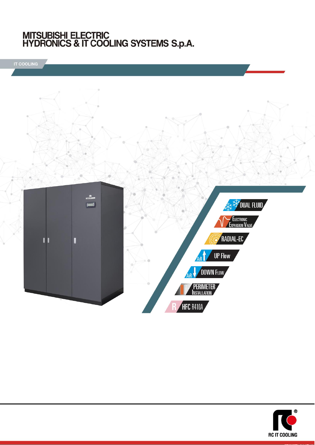
• PERIMETER INSTALLATION
• FULLY HERMETIC ON/OFF COMPRESSORS
• DUAL FLUID SYSTEM WITH ADDITIONAL COIL
• SINGLE OR DOUBLE REFRIGERANT CIRCUIT
• AIR DELIVERY FROM THE BOTTOM (UNDER) OR FROM THE TOP (OVER)
• PLUG FANS WITH EC ELECTRIC MOTOR
• ELECTRONIC EXPANSION VALVE
• AIR SUCTION TEMPERATURE UP TO 40°C
t-NEXT DF DX
10 – 149 kW
Air conditioners for IT Cooling with Dual Fluid system.
To be matched with remote air-cooled condenser.
Data Book: T_tNEXTDFDX_0719_EN
CLOSE CONTROL AIR CONDITIONERS
rcitcooling.com
Page 2

t-NEXT DF DX
T_tNEXTDFDX_0719_EN
2
MEHITS S.p.A.
DATA BOOK
INDEX
MEHITS CERTIFICATIONS ........................................................................................................................................................................................................... 4
GENERAL CHARACTERISTICS ................................................................................................................................................................................................... 5
INSTALLATION .............................................................................................................................................................................................................................. 6
PRODUCT FEATURES AND BENEFITS ...................................................................................................................................................................................... 6
F-GAS DIRECTIVE ........................................................................................................................................................................................................................ 6
MODEL IDENTIFICATION ............................................................................................................................................................................................................. 7
TRANSPORT AND STORAGE TEMPERATURE .......................................................................................................................................................................... 7
WORKING LIMITS ......................................................................................................................................................................................................................... 8
MAIN COMPONENTS .................................................................................................................................................................................................................... 9
REMOTE AIR-COOLED CONDENSERS .................................................................................................................................................................................... 11
OPTIONAL ACCESSORIES ........................................................................................................................................................................................................ 11
TECHNICAL DATA ...................................................................................................................................................................................................................... 14
DUAL FLUID SYSTEM ................................................................................................................................................................................................................. 18
2-WAY BALL VALVE FOR CHILLED WATER FLOW CONTROL .............................................................................................................................................. 19
WATER QUALITY OF THE HYDRAULIC CIRCUITS .................................................................................................................................................................. 20
ANTIFREEZE MIXTURES ........................................................................................................................................................................................................... 20
REFRIGERANT CHARGE ........................................................................................................................................................................................................... 21
PRESSURE RELIEF VALVE ....................................................................................................................................................................................................... 22
REFRIGERANT CIRCUIT ............................................................................................................................................................................................................ 23
RECOMMENDED REFRIGERANT LINES .................................................................................................................................................................................. 25
INSTALLATION DIAGRAM .......................................................................................................................................................................................................... 26
ACOUSTIC DATA ........................................................................................................................................................................................................................ 27
ELECTRICAL DATA ..................................................................................................................................................................................................................... 28
MICROPROCESSOR CONTROL SYSTEM ................................................................................................................................................................................ 29
DEMAND LIMIT ............................................................................................................................................................................................................................ 31
TEMPERATURE PROBE ON AIR RETURN / DELIVERY .......................................................................................................................................................... 31
CLOGGED FILTERS SENSOR ................................................................................................................................................................................................... 31
FLOOD SENSOR ......................................................................................................................................................................................................................... 31
POSSIBLE AIR INTAKE FOR OVER VERSIONS ....................................................................................................................................................................... 32
REMOTE AIR-COOLED CONDENSER ....................................................................................................................................................................................... 33
OPTIONAL ACCESSORIES: P121 – FRONT AIR INTAKE+BOTTOM PANEL .......................................................................................................................... 35
OPTIONAL ACCESSORIES: 601 – SOLENOID VALVE ON LIQUID LINE ................................................................................................................................ 35
OPTIONAL ACCESSORIES: A548 - CONSTANT PREVALENCE ............................................................................................................................................. 35
OPTIONAL ACCESSORIES: P091 - BACK-UP MODULE CONTROLLER ................................................................................................................................ 35
OPTIONAL ACCESSORIES: P171 – KIT FOR AIR -45°C MCH AXIAL AC ............................................................................................................................... 36
OPTIONAL ACCESSORIES: P172 – KIT FOR AIR -45°C AXIAL AC ........................................................................................................................................ 36
OPTIONAL ACCESSORIES: A492 – WATER LEACKAGE DETECTOR + ADDITIONAL DETECTOR..................................................................................... 37
OPTIONAL ACCESSORIES: A511 - SMOKE DETECTORS ...................................................................................................................................................... 37
OPTIONAL ACCESSORIES: A512 – FIRE DETECTORS .......................................................................................................................................................... 37
ACCESSORI: P181 – ANALIZZATORE DI RETE ....................................................................................................................................................................... 38
ACCESSORI: P182 – ANALIZZATORE DI RETE+OPTIONAL ................................................................................................................................................... 38
ACCESSORI: P183 – KIT ANALIZZATORE DI RETE ................................................................................................................................................................. 38
ACCESSORI: P184 – KIT ANALIZZATORE DI RETE+ OPTIONAL ........................................................................................................................................... 38
OPTIONAL ACCESSORIES: P021 – 2-WAY BALL BY-PASS VALVE ....................................................................................................................................... 39
OPTIONAL ACCESSORIES: A431 – ELECTRIC HEATERS ...................................................................................................................................................... 41
OPTIONAL ACCESSORIES: A432 – EXTRA POWER ELECTRIC HEATERS .......................................................................................................................... 41
OPTIONAL ACCESSORIES: 4301 – STEAM HUMIDIFIER 3KG/H ............................................................................................................................................ 43
OPTIONAL ACCESSORIES: 4303 – STEAM HUMIDIFIER 8KG/H ............................................................................................................................................ 43
OPTIONAL ACCESSORIES: 4305 – STEAM HUMIDIFIER 15KG/H .......................................................................................................................................... 43
OPTIONAL ACCESSORIES : P051 – DEHUMIDIFICATION FUNCTION .................................................................................................................................. 46
OPTIONAL ACCESSORIES: P161 - T/RH AIR INTAKE SENSOR ............................................................................................................................................. 46
Page 3

t-NEXT DF DX
T_tNEXTDFDX_0719_EN
3
MEHITS S.p.A.
DATA BOOK
OPTIONAL ACCESSORIES: P071 - REMOTE T/RH PROBE .................................................................................................................................................... 46
OPTIONAL ACCESSORIES: 4666 – EXTERNAL AIR PROBE .................................................................................................................................................. 46
OPTIONAL ACCESSORIES: P111 – DUAL POWER SUPPLY .................................................................................................................................................. 47
OPTIONAL ACCESSORIES: P112 – DUAL POWER SUPPLY + OPTIONAL ............................................................................................................................ 47
OPTIONAL ACCESSORIES: P113 – KIT DUAL POWER SUPPLY ........................................................................................................................................... 47
OPTIONAL ACCESSORIES: P114 – KIT DUAL POWER SUPPLY + OPTIONAL ..................................................................................................................... 47
OPTIONAL ACCESSORIES: A381 - DRAIN PUMP .................................................................................................................................................................... 48
OPTIONAL ACCESSORIES: P084 – AIR FILTER EPM
10
50% .................................................................................................................................................. 49
OPTIONAL ACCESSORIES: A531 – ON-OFF DAMPER ........................................................................................................................................................... 50
OPTIONAL ACCESSORIES: P011 - EMPTY PLENUM .............................................................................................................................................................. 52
OPTIONAL ACCESSORIES: P012 - EMPTY PLENUM CL.A1 ................................................................................................................................................... 52
OPTIONAL ACCESSORIES: P031 - EMPTY INTAKE PLENUM ................................................................................................................................................ 52
OPTIONAL ACCESSORIES: P032 - EMPTY INTAKE PLENUM CL.A1 ..................................................................................................................................... 52
OPTIONAL ACCESSORIES: P013 - PLENUM + 3 GRILLES ..................................................................................................................................................... 52
OPTIONAL ACCESSORIES: P014 - PLENUM + 3 GRILLES CL.A1 .......................................................................................................................................... 52
OPTIONAL ACCESSORIES: P015 - SILENCED PLENUM ........................................................................................................................................................ 52
OPTIONAL ACCESSORIES: P016 - SILENCED PLENUM + 1 GRILLE .................................................................................................................................... 52
OPTIONAL ACCESSORIES: P017 - PLENUM + FILTER EPM2.5 50% ..................................................................................................................................... 52
OPTIONAL ACCESSORIES: P018 - PLENUM + FILTER EPM1 50% ........................................................................................................................................ 52
OPTIONAL ACCESSORIES: P019 - PLENUM + FILTER EPM1 85% ........................................................................................................................................ 52
OPTIONAL ACCESSORIES: P034 – INTAKE FREE-COOLING PLENUM ................................................................................................................................ 59
OPTIONAL ACCESSORIES: P041 – SUPPORT FRAME H 255-350MM ................................................................................................................................... 63
OPTIONAL ACCESSORIES: P042 – SUPPORT FRAME H 355-450MM ................................................................................................................................... 63
OPTIONAL ACCESSORIES: P043 – SUPPORT FRAME H 400-510MM ................................................................................................................................... 63
OPTIONAL ACCESSORIES: 1511 – SOFT STARTER ............................................................................................................................................................... 64
OPTIONAL ACCESSORIES: A272 – CL.0 OR A1 (EN13501-1) INSULATION .......................................................................................................................... 65
MACHINE DRAWINGS ................................................................................................................................................................................................................ 66
HOLE IN THE RAISED FLOOR FOR DOWNFLOW VERSION .................................................................................................................................................. 83
EXAMPLE FOR MACHINES NOISE EMISSION CALCULATION............................................................................................................................................... 84
VALVE PRESSURE DROP CALCULATION AS FUNCTION OF WATER FLOW RATE ............................................................................................................ 86
AIR FILTERS REPLACEMENT .................................................................................................................................................................................................... 87
SHIPMENT: PACKING DIMENSIONS ......................................................................................................................................................................................... 88
SHIPMENT: SHIPPING WEIGHT ................................................................................................................................................................................................ 88
SHIPMENT: OPTIONALS PACKING DIMENSIONS AND SHIPPING WEIGHT ......................................................................................................................... 89
Page 4
t-NEXT DF DX
T_tNEXTDFDX_0719_EN
4
MEHITS S.p.A.
DATA BOOK
MEHITS CERTIFICATIONS
SYSTEM CERTIFICATIONS
ISO 9001 CERTIFICATION – MEHITS S.p.A.
Quality Management System
ISO 14001 CERTIFICATION – MEHITS S.p.A.
Environmental Management System
BS OHSAS 18001 CERTIFICATION – MEHITS S.p.A.
Occupational Health and Safety Management System
PRODUCT CERTIFICATIONS BY COUNTRY
CE MARKING
MEHITS units are in compliance with the European Directives in force.
CCC – CQC CERTIFICATION
(People’s Republic of China)
EAC CERTIFICATION
(Russian Federation, Belarus, Kazakhstan)
Page 5

t-NEXT DF DX
T_tNEXTDFDX_0719_EN
5
MEHITS S.p.A.
DATA BOOK
GENERAL CHARACTERISTICS
Air Conditioners for IT Cooling with Dual Fluid system.
• Direct expansion, air cooled.
For matching with remote air-cooled condenser;
• Two independent cooling systems:
Direct expansion coil; Chilled water coil;
• Plug fans with EC electric motors;
• Rotary or scroll on/off compressors;
• Single or double refrigerant circuit.
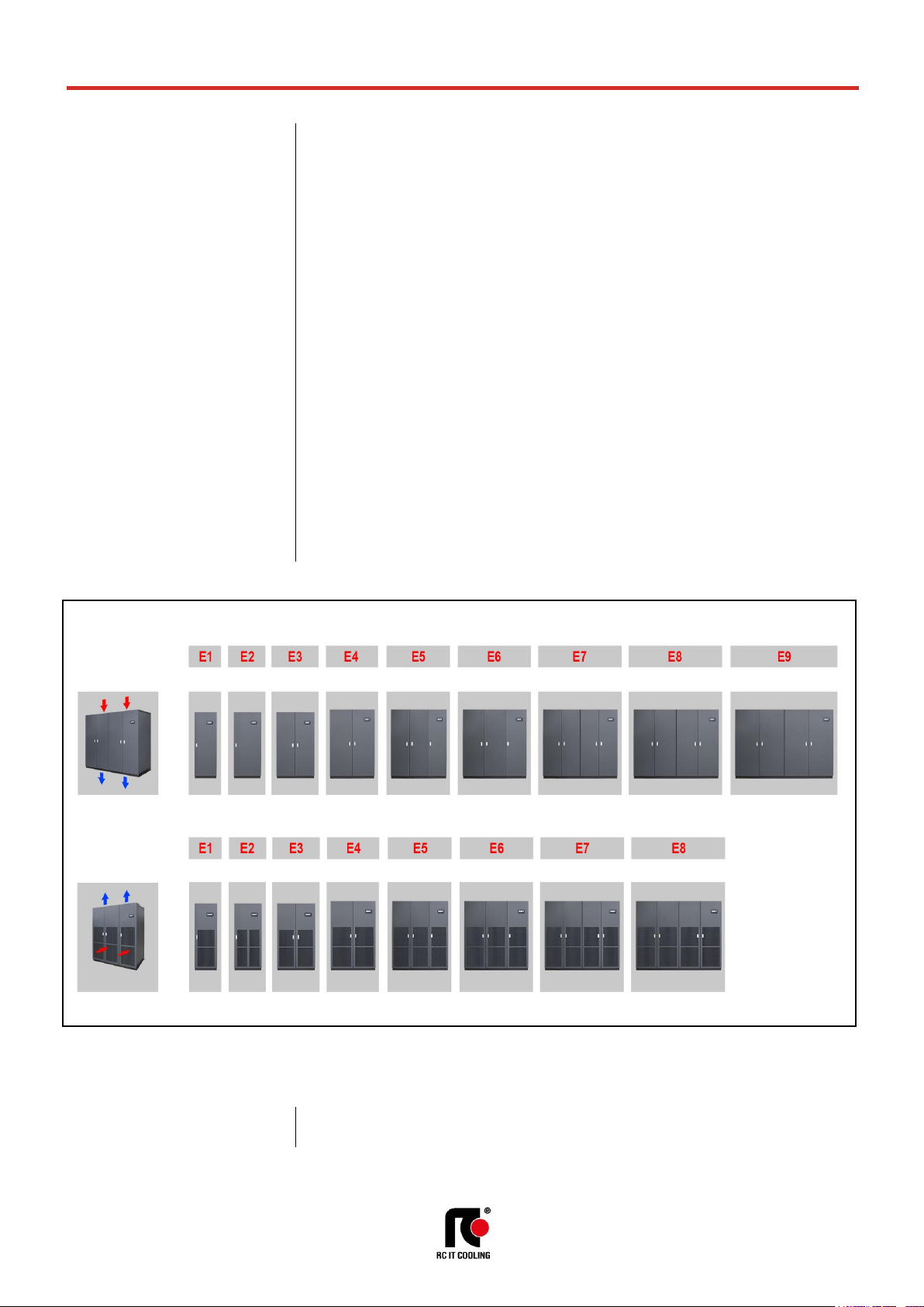
This series is offered in 20 models available in the following versions:
• The upflow version (Over) is characterized by air intake from the front through honeycomb grille
and air delivery from the top of the unit.
• The downflow version (Under) is characterized by air intake from the top and air delivery from
the bottom of the unit.
Cooling capacity: 10 ÷ 149 kW
The machines are made for indoor installation.
The constructive solutions and the internal lay-out allow high application flexibility and the frontal access to
the main components for the inspection and routine maintenance.
The installation requires refrigerant charge, electrical and hydraulic connections.
Final assembly on all machines before shipment including running test, reading and monitoring of operating
parameters, alarms simulation and visual check.
UNDER
Downflow air delivery
OVER
Upflow air delivery
UNDER
Downflow air delivery
OVER
Upflow air delivery
Air conditioner
Remote
condenser
Liquid chiller
Page 6
t-NEXT DF DX
T_tNEXTDFDX_0719_EN
6
MEHITS S.p.A.
DATA BOOK
INSTALLATION
The series is particularly suitable for installation in Data Centre of medium / small size with constant load.
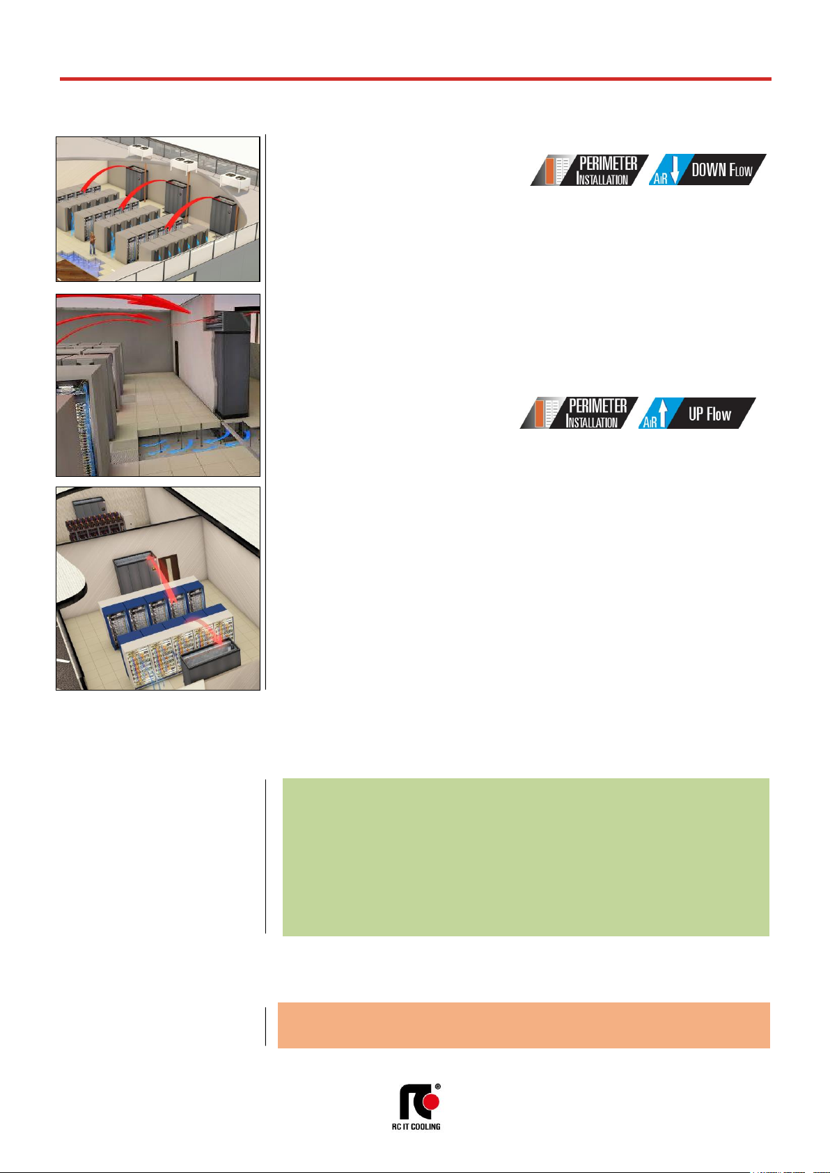
DOWNFLOW VERSION (Under)
Typical installation is on the perimeter.
The units are placed along the perimeter of the Data Center. Air suction from the top of the unit and air
delivery in the underfloor void.
The air distribution is achieved by special tiles placed in front of the racks row, forming cold aisle for air
diffusion. On the rear of the racks is expelled the hot then aspirated by the unit.
For an optimal installation is advisable to provide the cold aisle containment.
Some solutions provide a service corridor around the server rooms where to place the units. In this case, it
is necessary to provide the air intake plenum for each unit. With this solution, all the space in the Data
Center is available for the installation of racks.
UPFLOW VERSION (Over)
The type of installation is practically similar to the previous. The only difference is that for the air distribution
in the Data Center is not used the raised floor but ducts in the ceiling.
The series is also suitable for installation in UPS, Batteries, Distribution rooms and in all service areas of
the Data Center that need a service of conditioning.
OPTIONAL
An extensive list of accessories allows the unit to adapt effectively to the real needs of the system, reducing
the time and cost of installation.
PRODUCT FEATURES AND BENEFITS
• Dual Fluid System: Two independent cooling systems: Chilled water coil; Direct expansion coil
• Electronic expansion valve;
• New plug fans with EC electric motors and impeller in composite material, which guarantees a
reduction of power consumption;
• New fans electric motor that do not require maintenance;
• Improvement of the control software with advanced control logic;
• Single or double refrigerant circuit;
• Air suction temperature up to 40°C
F-GAS DIRECTIVE
The units highlighted in this publication contain <HFC R410A [GWP
100
2088]> fluorinated
greenhouse gases.
Page 7
t-NEXT DF DX
T_tNEXTDFDX_0719_EN
7
MEHITS S.p.A.
DATA BOOK
MODEL IDENTIFICATION
Air conditioners for IT Cooling
model: t-NEXT DF DX O 041 P1 S E4
t-NEXT Series
DF DX Unit type
DF – with dual fluid system
Two independent cooling systems:
Direct expansion coil, chilled water coil,
DX – direct expansion, air cooled
O Air delivery
O = over – upflow air delivery
U = under – downflow air delivery
041 Model / Cooling capacity (kW) at nominal conditions
P1 Compressor type and number
P = scroll compressor for R410A
1 = number of compressors
S Refrigerant circuit
S = single
D = double
E4 Size
TRANSPORT AND STORAGE TEMPERATURE
During transport and if the machine is not installed at the reception, do not remove the packaging and place
the machine in an enclosed, dry and protected from sunlight site at temperatures ranging between -30°C
and 50°C in absence of superficial condensation.
THE RANGE
UNDER
OVER
Page 8
t-NEXT DF DX
T_tNEXTDFDX_0719_EN
8
MEHITS S.p.A.
DATA BOOK
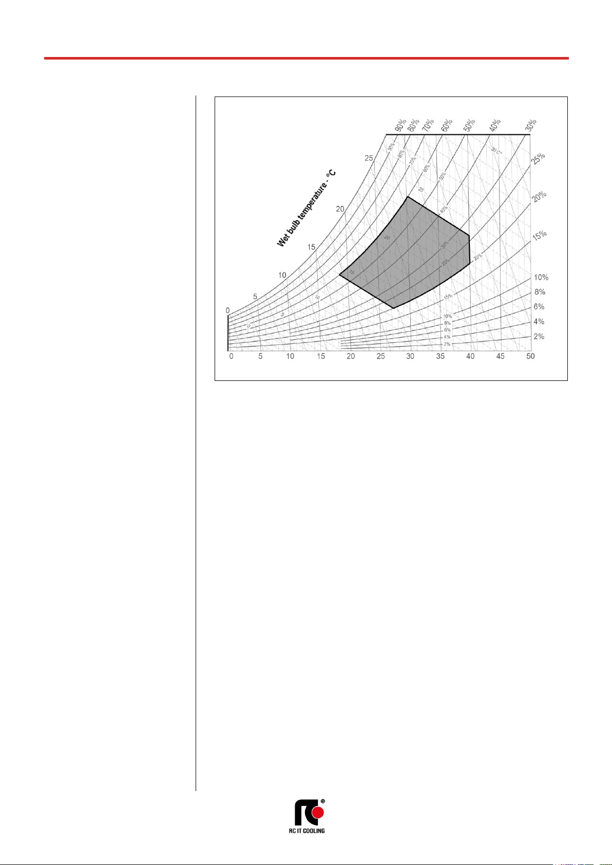
WORKING LIMITS
ROOM AIR CONDITIONS
Room air temperature:
14°C minimum temperature with wet bulb.
24°C maximum temperature with wet bulb.
18°C minimum temperature with dry bulb
40°C maximum temperature with dry bulb.
AREA “A”. Machine operating envelope.
Room air humidity:
20%RH minimum relative humidity.
60%RH maximum relative humidity.
AMBIENT AIR TEMPERATURE
45°C Maximum ambient air temperature
-20°C Minimum ambient air temperature
With “Kit for air -45°C” for low ambient temperature operation (optional)
-45°C minimum ambient air temperature with remote condensers with AC fans
CHILLED WATER TEMPERATURE (Dual Fluid circuit)
6-25°C temperature range of the water entering the coil
ΔT 3°C Minimum temperature difference between water inlet and outlet
ΔT 10°C Maximum temperature difference between water inlet and outlet
All the values are indicative. The working temperatures are influenced by a series of variables as:
• Working conditions;
• Thermal load;
• Set of the microprocessor control.
HYDRAULIC CIRCUIT (Dual Fluid circuit)
ΔP 5-150kPa Pressure drop range of the hydraulic circuit.
10 Bar Maximum working pressure of the hydraulic circuit
POWER SUPPLY
± 10% Maximum tolerance of the supply voltage (V)
± 2% Maximum unbalancing of the phases.
A
Relative humidity
- %
Relative humidity - %
Dry bulb temperature - °C
Page 9
t-NEXT DF DX
T_tNEXTDFDX_0719_EN
9
MEHITS S.p.A.
DATA BOOK
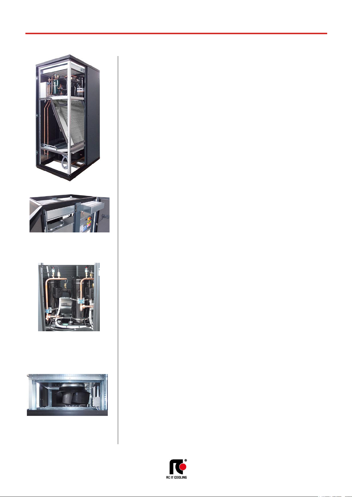
MAIN COMPONENTS
FRAMEWORK
• Base in aluminium extrusion, painted with epoxy powders. Colour RAL 9005;
• Frame in aluminium profile, painted with epoxy powders. The inner frame is provided with
seals for the panels. Colour RAL 9005;
• Panels in galvanized steel sheet with protective surfaces treatment in compliance with UNI
ISO 9227/ASTMB117 and ISO 7253, and painted with epoxy powders. Colour RAL 7016
hammered;
• Panels insulated with polyurethane foam and seals to ensure air tight.
• Hinged front panels with quick release removal system.
• Total front access for routine maintenance.
• Removable lateral and back side panels.
• Air flow OVER version:
- Air intake from the front through honeycomb type grille and air delivery from the top.
• Air flow UNDER version:
- Air intake from the top and air delivery from the bottom.
• Compartment for electrical panel on unit front for direct access to control and regulation
devices;
FILTER SECTION
• Washable air filters with COARSE 60% efficiency (according to ISO EN 16890), with cells in
synthetic fibre and metallic frame.
• Air filters access:
OVER version
- Frontal access for all machines
UNDER version
- For machines size E1 – E2 – E3 frontal access
- For machine size E4 – E5 – E6 – E7 – E8 – E9 access from upper side
• Clogged filters sensor with differential pressure switch on air side.
ON / OFF COMPRESSORS SECTION
Units size E1 and E2:
• Rotary vane compressors for R410A refrigerant
• 2-pole 3-phase electric motor with direct on line starting.
• Crankcase heater.
• Rubber supports.
Units size E3, E4, E5, E6, E7, E8 and E9
• Scroll rotary compressors with spiral profile optimized for R410A refrigerant.
• 2-pole 3-phase electric motor with direct on line starting.
• Crankcase heater.
• Rubber supports.
FANS SECTION
The fan section is contained within the machine and includes:
• Centrifugal fans with backward curved blades with wing profile, single suction and without
scroll housings (Plug-fans), directly coupled to external rotor electric motor.
• Impeller in composite material exempt from rust formation.
• Brushless type synchronous EC motor with integrated electronic commutated system and
continuous variation of the rotation speed. The motor rotation control is obtained with the EC
system (Electronic Commutation) that manage the motor according to the signal coming from
the microprocessor control.
• Fans control through ModBus. In case of failure, the control stops the interested fan indicating
the type of fault. The machine with more than one fan is not stopped.
• Adjustable External Static Pressure (ESP).
• Fan guard with rubber support (UNDER version)
Page 10
t-NEXT DF DX
T_tNEXTDFDX_0719_EN
10
MEHITS S.p.A.
DATA BOOK
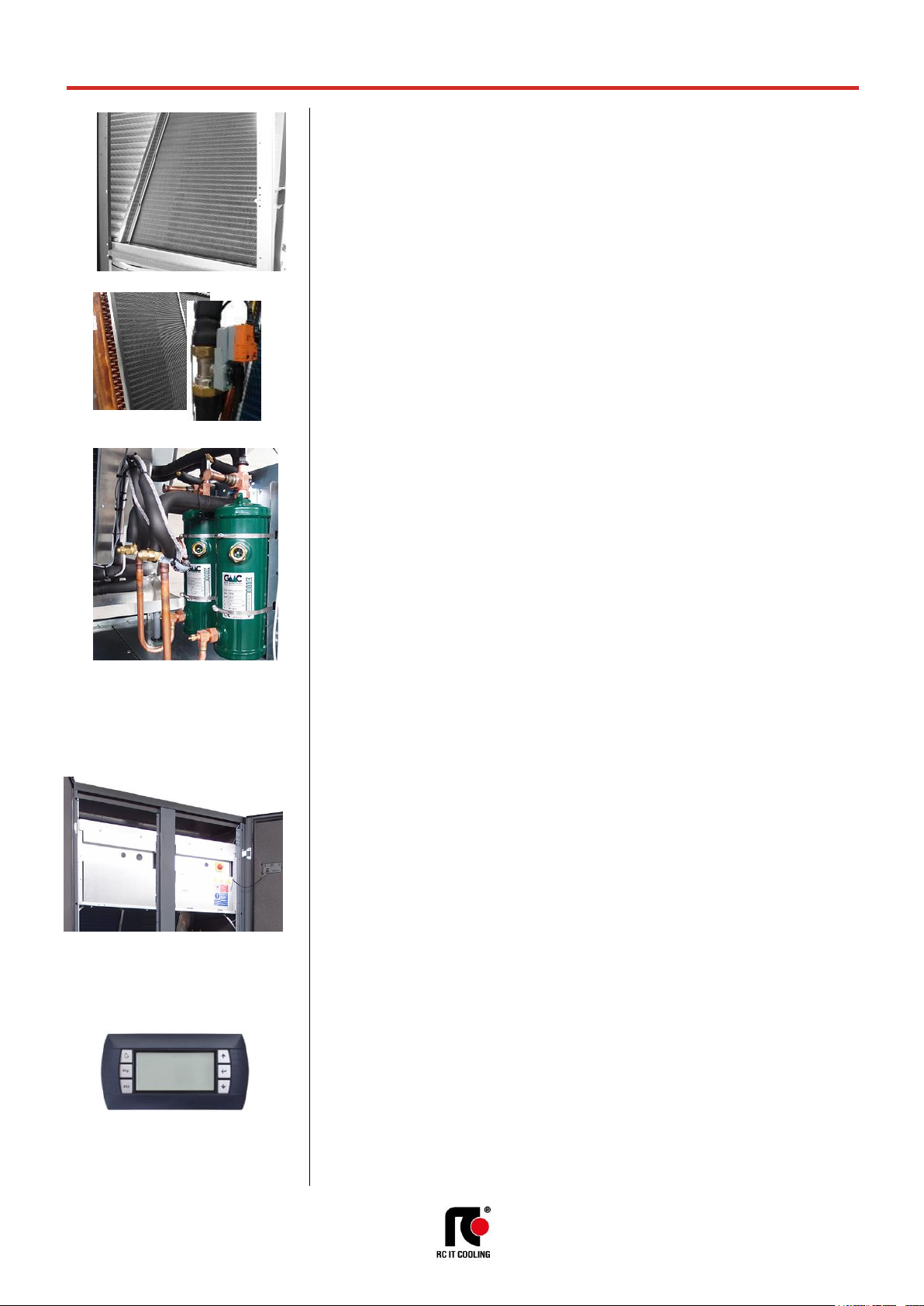
COOLING SECTION – DIRECT EXPANSION COIL
• Heat exchanger coil with internally corrugated copper tubes and high efficiency aluminium
fins, specifically developed to provide high heat transfer and lower pressure drops.
• Frame in galvanized steel or peraluman.
• Condensate tray in peraluman with PVC flexible discharge pipe.
• Temperature sensor on air intake with control and regulation functions.
• Temperature sensor on air delivery with function of temperature display.
• Under floor water alarm through sensor to be placed on the floor.
COOLING SECTION – CHILLED WATER COIL
• Chilled water 4 rows cooling coil with copper tubes, aluminium fins and galvanized steel
frame.
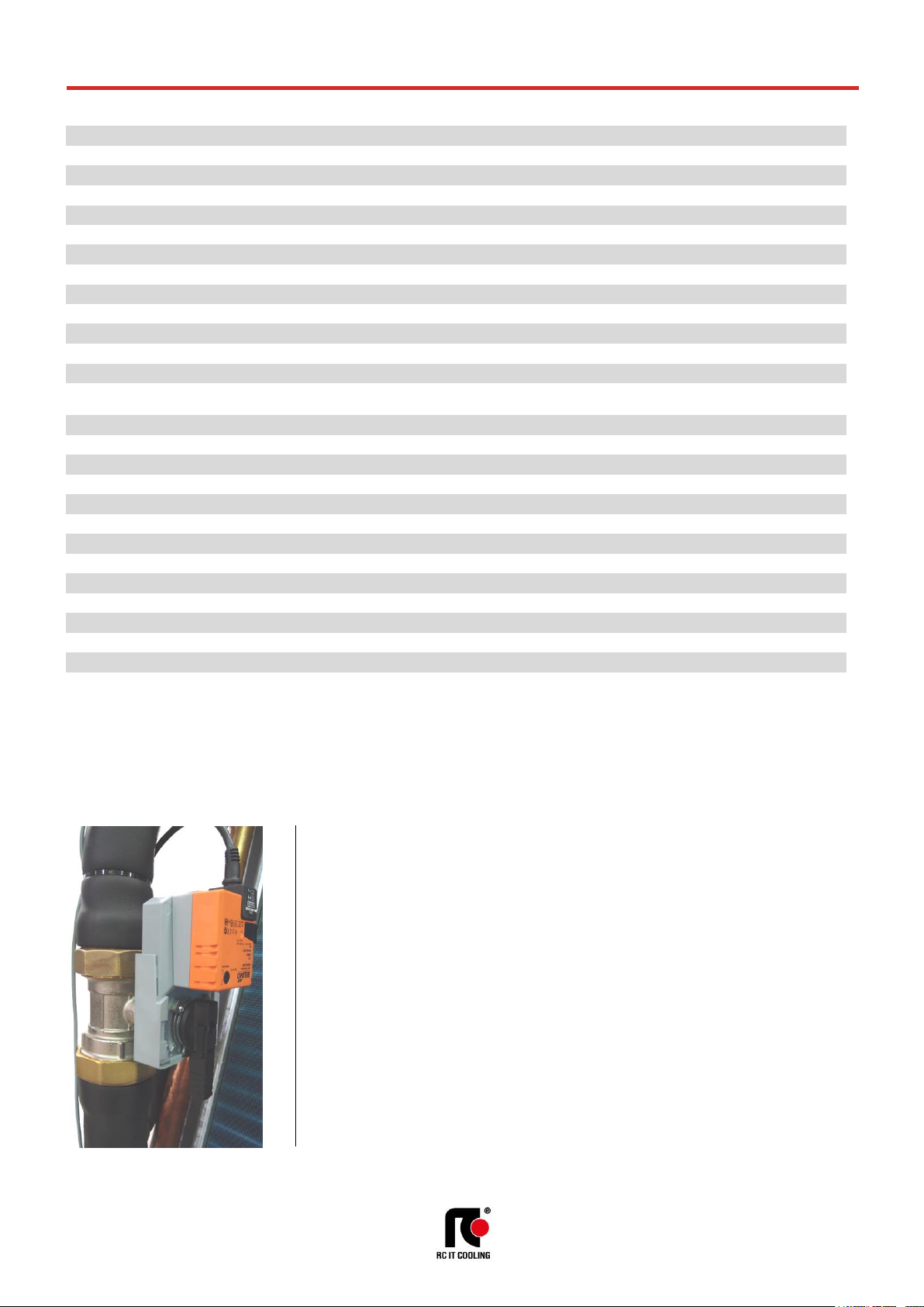
• 2-way motorized valve with 0÷10 VDC control actuator and emergency manual control.
• Temperature probe on water inlet.
• Hydraulic pipes in copper with anticondensate insulation
REFRIGERANT CIRCUIT
The air conditioner is supplied with a minimum R410A refrigerant charge.
Components for each refrigerant circuit:
• Electronic expansion valve. The valve allows high performance and system efficiency thanks
to a timely and accurate response to changes in temperature and pressure.
• Sight glass.
• Filter dryer on liquid line.
• Pressure transducers with indication, control and protection functions, on low and high
refrigerant pressure.
• High pressure safety switch with manual reset.
• Liquid receiver.
• Pressure relief valve on liquid receiver for models 041 P1, 045 P1, 075 P2, 082 P2,
092 P2, 102 P2, 117 P4, 146 P4.
• Refrigerant circuit with copper tubing with anticondensate insulation of the suction line.
• Lubricant oil charge.
• Valves on gas delivery and liquid return for coupling to remote air-cooled condenser.
• 0÷10V proportional signal to manage the condensing control system of the remote air-cooled
condenser.
• Condensing control by continuous variation of remote condenser fan rotation speed for
operations with ambient temperature down to -20°C.
ELECTRICAL PANEL
In accordance with EN60204-1 norms, suitable for indoor installation, complete with:
• Main switch with door lock safety on frontal panel.
• Magnetothermic switches for each compressor.
• Magnetothermic switches for supply fans.
• Contactors for each load. The supply fans equipped with EC electric motor don’t require
contactors.
• Transformer for auxiliary circuit and microprocessor supply.
• Numbered wirings.
• Terminals:
OUTLETS
- Voltage free deviating contact for General Alarm 1-2
- Voltage free contact for supply fans status.
- Voltage free contact for smoke / fire sensor (the sensors are accessory)
INLETS
- External enabling.
• Power supply 400/3+N/50.
CONTROL SYSTEM
Microprocessor control system with graphic display for control and monitor of operating and alarms
status. The system includes:
• Built-in clock for alarms date and time displaying and storing;
• Built-in memory for the storing of the intervened events (up to 200 events recorded);
• Predisposition for additional connectivity board housing (MODBUS, LON,
BACNET MS/TP RS485, BACNET OVER IP). The electronic cards are optional accessories.
• Main components hour-meter;
• Non-volatile “Flash” memory for data storage in case of power supply faulty;
• Menu with protection password;
• Demand Limit function;
• LAN connection (max 10 units).
Page 11

t-NEXT DF DX
T_tNEXTDFDX_0719_EN
11
MEHITS S.p.A.
DATA BOOK
REMOTE AIR-COOLED CONDENSERS
The descriptions of these series can be found in Chapter REMOTE AIR-COOLED CONDENSERS.
............................................ Remote air-cooled condenser: Remote air-cooled condenser in
PERALUMAN aluminium alloy with microchannel condensing coil:
P821 - with AC axial fans and standard acoustic version
series GR-Z A B 50;
P831 - with AC axial fans and low noise acoustic version
series GR-Z A L 50;
P841 - with EC axial fans and standard acoustic version
series GR-Z E B 50;
P851 - with EC axial fans and low noise acoustic version
series GR-Z E L 50.
Remote air-cooled condenser with condensing coil with copper tubes and
aluminium fins:
- with AC axial fans series T-MATE DX-A;
- with EC axial fans series T-MATE DX-E;
- with EC plug-fans series T-MATE DX-PF-E.
OPTIONAL ACCESSORIES
The descriptions of these additional components can be found in Chapter OPTIONAL ACCESSORIES.
P121 .................................... Front air intake + bottom panel. Unit base noise insulation with special
bottom panel for OVER version. Restriction: Non-compatible with “P122
Bottom air intake + blind panels” for OVER version.
P122 .................................... Bottom air intake+blind panels. Blind frontal panel for OVER version. The
accessory allows the intake air from the bottom of the machine. Restriction:
Not compatible with “P121 Front air intake + bottom panel” for OVER
version.
601 ...................................... Solenoid valve on liquid line.
A548 .................................... Constant prevalence. Automatic system for the air pressure control in the
aisle. The system controls the supply fans rotation speed to keep constant
the air pressure via a differential pressure transmitter connected to the
microprocessor control.
P091 .................................... Back-up module controller. The system guarantees the microprocessor
power supply for a few minutes, in case of supply voltage failure. (size E1
excluded).
P171 .................................... Kit for air -45°C MCH axial AC (condenser series GR). Kit for operations
with low ambient air temperature down to -45°C. For machine start up and
operation with very low ambient air temperatures (between -20°C and 45°C).
P172 (1) .............................. Kit for air -45°C axial AC (condenser series T-MATE). Kit for operations
with low ambient air temperature down to -45°C. For machine start up and
operation with very low ambient air temperatures (between -20°C and 45°C).
P191 .................................... Power supply for condenser. Electrical power supply for remote
condenser from the indoor machine electrical board. The optional includes
magneto-thermic switches for condenser fans and the control/alarm signals.
383 ...................................... Numbered wirings + UK requests;
4181 / 4182 / 4184 / 4185 ... Serial cards:
4181 – Serial card MODBUS;
4182 – Serial card LON;
4184 – Serial card BACNET MS/TP RS485;
4185 – Serial card BACNET OVER IP.
A492 .................................... Water leakage detector + additional sensor. Supplied in mounting kit.
A511 .................................... Smoke detector. Supplied in mounting kit.
A521 .................................... Fire detector. Supplied in mounting kit.
P141 .................................... Analogue set-point compensation. - Analogue set point compensation
according to an external analogue signal at Customer care.
The microprocessor control, through the additional module “expansion
card”, can manage a compensation signal of the return air setpoint by
analogue input (0...1V; 0...5V; 0,5...4,5V; 4...20mA; 0...20mA). The
compensation curve allows to assign a temperature setpoint offset
respectively to the minimum and maximum signal managed by the input.
Page 12

t-NEXT DF DX
T_tNEXTDFDX_0719_EN
12
MEHITS S.p.A.
DATA BOOK
P181 .................................... Network analyser (standard machine) Multifunction utility for calculating and
displaying the machine electrical measurements.
P182 .................................... Network analyser+optional (full optional machine) Multifunction utility for
calculating and displaying the machine electrical measurements.
P183 .................................... Kit network analyser (standard machine) Multifunction utility for calculating
and displaying the machine electrical measurements. Supplied in mounting
kit.
P184 .................................... Kit network analyser+optional (full optional machine) Multifunction utility
for calculating and displaying the machine electrical measurements. Supplied
in mounting kit.
A812 (2) .............................. Free-cooling direct control.
P021 .................................... 2 way 0-10V modulating water valve.2-way motorized valve with 0÷10
VDC control actuator and emergency manual control for the third way (bypass) of the chilled water hydraulic circuit. The valve is in combination with
the main water flow control valve
A431 .................................... Electric heater. Heating with electric heaters.
A432 .................................... Extra power electric heater. Size E1, E2 excluded.
4301 / 4303 / 4305 (3) ......... Humidification: Modulating steam humidifier with immersed electrodes
with electronic control.
4301 - Steam humidifier 3kg/h
4303 - Steam humidifier 8kg/h
4305 - Steam humidifier 15kg/h
P051 (4) .............................. Dehumidification function.
P161 .................................... T/rH air intake sensor. Combined Temperature / Humidity sensor on air
intake. The optional replace the standard temperature sensor on machine
air intake.
4666 .................................... External air probe. External air temperature probe.
P071 .................................... Remote T/rH probe. Combined Temperature / Humidity sensor for remote
installation. The optional is added to the standard temperature sensor on
machine air intake.
P111 / P112 / P113 / P114 . Dual power supply. Dual power supply with automatic change-over.
P111 - Dual power supply.
P112 - Dual power supply + optional.
P113 - Dual power supply kit. Supplied in mounting kit
P114 - Dual power supply kit + optional. Supplied in mounting kit
A381 .................................... Drain pump. Supplied in mounting kit. The system includes pump with
activation float and 10 linear meters long discharge pipe.
P084 .................................... Air filter ePM10 50%. Washable high efficiency air filter (according to ISO
EN 16890). Not compatible with “P017 / P018 / P019 Plenum + filter ePM
2.5
50%, ePM1 50%, ePM1 85% (according to ISO EN 16890)”.
A531 (5) .............................. On-off damper. Non-return air damper with frame driven by electric
servomotor installed on the machine air delivery.
P011 .................................... Empty plenum.
P012 .................................... Empty plenum CL.A1. Plenum with fire reaction in class “0” or “A1”.
P013 .................................... Plenum + 3 grilles on three sides with double adjustable row.
P014 .................................... Plenum + 3 grilles CL.A1. Plenum with grilles on three sides with double
adjustable row, with fire reaction in class “0” or “A1”.
P015 .................................... Silenced plenum. Not compatible with “P084 Air filter ePM10 50%.”.
P016 .................................... Silenced plenum + 1 grille. Grille with double adjustable row on front side
and sound absorbers.
P017 .................................... Plenum + filter ePM
2,5
50%. Plenum with high efficiency air filter (according
to ISO EN 16890). Not compatible with “P084 Air filter ePM10 50%.”.
P018 .................................... Plenum + filter ePM1 50%. Plenum with high efficiency air filter (according
to ISO EN 16890). Not compatible with “P084 Air filter ePM10 50%.”.
P019 .................................... Plenum + filter ePM1 85%. Plenum with high efficiency air filter (according
to ISO EN 16890). Not compatible with “P084 Air filter ePM10 50%.”.
P031 (6) .............................. Empty intake plenum.
P032 (6) .............................. Empty intake plenum CL.A1. Plenum with fire reaction in class “0” or “A1”.
(size E0 excluded).
P034 (7) .............................. Intake free-cooling plenum.
P041 / P042 / P043 ............. Support frame with height adjusting rubber holders. Supplied in mounting
kit. It is not possible to match the support frame with plenum installed under
the machine.
P041 – Support frame h 255-350mm
P042 – Support frame h 355-450mm
P043 – Support frame h 400-510mm
3601 .................................... Compressor operating signal contact. Voltage free contact for
compressor status signalling.
Page 13

t-NEXT DF DX
T_tNEXTDFDX_0719_EN
13
MEHITS S.p.A.
DATA BOOK
2411 .................................... Phase sequence relay. Phases sequence control relay for the machine.
The system checks that the phase sequence of the power supply is correct
to prevent the opposite rotation of the three phase electric motors of the
machine as compressors. The optional is installed in the electrical box
downstream the main switch with door lock safety and in case of wrong
phase sequence prevents starting the machine;
1511 .................................... Soft starter. Compressor motors soft-starter system (size E1, E2
excluded).
3301 .................................... Compressor rephasing. Compressors capacitor for power factor - cosφ
0,9 (sizes E1, E2 excluded).
A181 .................................... Compressor soundproof jacket. Compressor soundproof jacket for a
sound level reduction of 2 dB(A).
A272 .................................... CL. 0 or A1 (EN 13501-1) insulation: Panelling with fire reaction in class
“0” or “A1;
P151 .................................... Lowered display for Under – for UNDER units equipped with plenum
under the unit.
9973 .................................... Wooden cage packing. The machines are delivered on wooden pallet,
covered with shrink wrap and packaged in wooden cage.
7387012600 ........................ Remote terminal. Graphic display for remote installation, the optional is
added to the standard graphic display placed on machine frontal panel.
WARNING
The Manufacturers reserves the right to accept the matching of the optional installed on the
machine.
MANDATORY COMBINATIONS OF ACCESSORIES
1. When optional accessory “P172 Kit for air -45°C axial AC” is present, it requires mandatory
accessory “P191 Power supply for condenser”.
2. When optional accessory “A812 Free cooling direct control” is present, it requires mandatory
accessories “P161 T/rH air intake sensor“ and “4666 External air probe”.
3. When optional accessories “4301 / 4303 / 4305 Steam humidifier” are present, they require
mandatory accessory “P161 T/rH air intake sensor“.
4. When optional accessory “P051 Dehumidification function” is present, it requires mandatory
accessory “P161 T/rH air intake sensor“.
5. When optional accessory “A531 On-off damper” is present, it requires mandatory accessory
“9973 Wooden cage packing”.
6. When optional accessories “P031 Empty intake plenum, for OVER version” and “P032 Empty
intake plenum CL.A1, for OVER version” are present, they require mandatory accessory “P122
Bottom air intake+blind panels, for OVER version only”
7. When optional accessory “P034 Intake free-cooling plenum” is present, it requires mandatory
accessories “P161 T/rH air intake sensor“, “4666 External air probe”, “A812 Free-cooling direct
control” and “P122 Bottom air intake+blind panels, for OVER version only”
Page 14

t-NEXT DF DX
T_tNEXTDFDX_0719_EN
14
MEHITS S.p.A.
DATA BOOK
TECHNICAL DATA
VERSION (1)
U / O
U / O
U / O
U / O
U / O
MODEL 011 P1 S
014 P1 S
016 P1 S
020 P1 S
022 P1 S
SIZE E1
E2
E2
E3
E3
COOLING CAPACITY (2)
Total
kW
10,3
13,8
16
20,3
22,1
Sensible
kW
10,2
13,8
14,8
20,3
22,1
SHR (3) 0,99 1 0,92 1 1
Total power input (Comp. + Fans)
kW
2,64
3,27
3,74
4,54
5,5
"EC" SUPPLY FANS
n. 1 1 1 1
1
Air flow
m³/h
2800
4000
4200
5700
6100
Nominal external static pressure
Pa
20
20
20
20
20
Maximum external static pressure
Pa
29
329
276
803
729
Fans power input (4)
kW
0,35
0,5
0,57
0,85
1,04
ON/OFF COMPRESSORS
rotary vane
rotary vane
rotary vane
scroll
scroll
Compressors number
n. 1 1 1 1
1
Capacity steps
n. 1 1 1 1
1
Compressors power input
kW
2,29
2,77
3,16
3,69
4,46
AIR FILTERS
n. 1 1 1 2
2
Filter area
m2
0,61
0,78
0,78
1,24
1,24
Efficiency (ISO EN 16890)
COARSE
60%
60%
60%
60%
60%
REFRIGERANT CIRCUITS
n. 1 1 1 1
1
POWER SUPPLY
V/Ph/Hz
400/3+N/50
400/3+N/50
400/3+N/50
400/3+N/50
400/3+N/50
ENERGY EFFICIENCY INDEX (2) (5)
EER Energy Efficiency Ratio
kW/kW
3,90
4,22
4,28
4,47
4,02
DIMENSIONS
Length
mm
650
785
785
1085
1085
Width
mm
675
675
675
775
775
Height
mm
1925
1925
1925
1925
1925
NET WEIGHT OVER
kg
248
283
288
333
338
NET WEIGHT UNDER
kg
258
293
298
353
358
REFRIGERANT CONNECTIONS
Gas delivery
ODS Ø
12
16
16
16
16
Liquid return
ODS Ø
12
12
12
16
16
HYDRAULIC CONNECTIONS
CONDENSATE DISCHARGE
Rubber pipe – internal diameter
Ø mm
19
19
19
19
19
THE COOLING CAPACITY DOES NOT CONSIDER THE SUPPLY FAN MOTOR THERMAL LOAD
1. U = Under, downflow / O = Over, upflow
2. Gross value. Characteristics referred to entering air at 26°C-40%RH; condensing temperature 45°C. ESP=20Pa.
3. SHR = Sensible cooling capacity / Total cooling capacity.
4. Corresponding to the nominal external static pressure
5. The Energy Efficiency Index does not consider the remote air-cooled condenser.
The units highlighted in this publication contain <HFC R410A [GWP
100
2088]> fluorinated greenhouse gas
Page 15

t-NEXT DF DX
T_tNEXTDFDX_0719_EN
15
MEHITS S.p.A.
DATA BOOK
TECHNICAL DATA
VERSION (1)
U / O
U / O
U / O
U / O
U / O
MODEL 026 P1 S
032 P1 S
037 P1 S
041 P1 S
045 P1 S
SIZE E3
E4
E4
E4
E4
COOLING CAPACITY (2)
Total
kW
26,2
32,5
37,6
41,4
45,4
Sensible
kW
25,3
32,5
37,6
41,2
43,4
SHR (3) 0,97 1 1 1 0,96
Total power input (Comp. + Fans)
kW
6,74
7,62
9,25
10,2
11,2
"EC" SUPPLY FANS
n. 1 1 1 1
1
Air flow
m³/h
6400
8700
10000
10800
10800
Nominal external static pressure
Pa
20
20
20
20
20
Maximum external static pressure
Pa
665
512
175
332
332
Fans power input (4)
kW
1,19
1,42
2,1
2,08
2,08
ON/OFF COMPRESSORS
scroll
scroll
scroll
scroll
scroll
Compressors number
n. 1 1 1 1
1
Capacity steps
n. 1 1 1 1
1
Compressors power input
kW
5,55
6,2
7,16
8,1
9,13
AIR FILTERS
n. 2 2 2 2
2
Filter area
m2
1,24
2,07
2,07
2,07
2,07
Efficiency (ISO EN 16890)
COARSE
60%
60%
60%
60%
60%
REFRIGERANT CIRCUITS
n. 1 1 1 1
1
POWER SUPPLY
V/Ph/Hz
400/3+N/50
400/3+N/50
400/3+N/50
400/3+N/50
400/3+N/50
ENERGY EFFICIENCY INDEX (2) (5)
EER Energy Efficiency Ratio
kW/kW
3,89
4,27
4,06
4,06
4,05
DIMENSIONS
Length
mm
1085
1305
1305
1305
1305
Width
mm
775
930
930
930
930
Height
mm
1925
1980
1980
1980
1980
NET WEIGHT OVER
kg
338
462
467
479
487
NET WEIGHT UNDER
kg
358
472
477
489
497
REFRIGERANT CONNECTIONS
Gas delivery
ODS Ø
22
22
22
22
22
Liquid return
ODS Ø
16
16
16
22
22
HYDRAULIC CONNECTIONS
CONDENSATE DISCHARGE
Rubber pipe – internal diameter
Ø mm
19
19
19
19
19
THE COOLING CAPACITY DOES NOT CONSIDER THE SUPPLY FAN MOTOR THERMAL LOAD
1. U = Under, downflow / O = Over, upflow
2. Gross value. Characteristics referred to entering air at 26°C-40%RH; condensing temperature 45°C. ESP=20Pa.
3. SHR = Sensible cooling capacity / Total cooling capacity.
4. Corresponding to the nominal external static pressure
5. The Energy Efficiency Index does not consider the remote air-cooled condenser.
The units highlighted in this publication contain <HFC R410A [GWP
100
2088]> fluorinated greenhouse gas
Page 16

t-NEXT DF DX
T_tNEXTDFDX_0719_EN
16
MEHITS S.p.A.
DATA BOOK
TECHNICAL DATA
VERSION (1)
U / O
U / O
U / O
U / O
U / O
MODEL 039 P2 D
048 P2 D
055 P2 D
062 P2 D
075 P2 D
SIZE E5
E5
E6
E6
E7
COOLING CAPACITY (2)
Total
kW
38,1
48,6
55,1
61,9
75,4
Sensible
kW
38,1
47,4
55,1
60,6
75,4
SHR (3) 1
0,98 1 0,98
1
Total power input (Comp. + Fans)
kW
9,21
12,5
13,5
15,1
17,9
"EC" SUPPLY FANS
n. 1 1 2 2
2
Air flow
m³/h
10000
12000
15000
15600
20000
Nominal external static pressure
Pa
20
20
20
20
20
Maximum external static pressure
Pa
259
206
654
592
438
Fans power input (4)
kW
1,82
2,31
2,4
2,68
3,6
ON/OFF COMPRESSORS
scroll
scroll
scroll
scroll
scroll
Compressors number
n. 2 2 2 2
2
Capacity steps
n. 2 2 2 2
2
Compressors power input
kW
7,39
10,2
11,1
12,4
14,3
AIR FILTERS
n. 3 3 3 3
4
Filter area
m2
2,59
2,59
3,16
3,16
3,82
Efficiency (ISO EN 16890)
COARSE
60%
60%
60%
60%
60%
REFRIGERANT CIRCUITS
n. 2 2 2 2
2
POWER SUPPLY
V/Ph/Hz
400/3+N/50
400/3+N/50
400/3+N/50
400/3+N/50
400/3+N/50
ENERGY EFFICIENCY INDEX (2) (5)
EER Energy Efficiency Ratio
kW/kW
4,14
3,89
4,08
4,10
4,21
DIMENSIONS
Length
mm
1630
1630
1875
1875
2175
Width
mm
930
930
930
930
930
Height
mm
1980
1980
1980
1980
1980
NET WEIGHT OVER
kg
584
594
684
704
777
NET WEIGHT UNDER
kg
594
604
694
714
834
REFRIGERANT CONNECTIONS
Gas delivery
ODS Ø
2x16
2x16
2x22
2x22
2x22
Liquid return
ODS Ø
2x16
2x16
2x16
2x16
2x22
HYDRAULIC CONNECTIONS
CONDENSATE DISCHARGE
Rubber pipe – internal diameter
Ø mm
19
19
19
19
19
THE COOLING CAPACITY DOES NOT CONSIDER THE SUPPLY FAN MOTOR THERMAL LOAD
1. U = Under, downflow / O = Over, upflow
2. Gross value. Characteristics referred to entering air at 26°C-40%RH; condensing temperature 45°C. ESP=20Pa.
3. SHR = Sensible cooling capacity / Total cooling capacity.
4. Corresponding to the nominal external static pressure
5. The Energy Efficiency Index does not consider the remote air-cooled condenser.
The units highlighted in this publication contain <HFC R410A [GWP
100
2088]> fluorinated greenhouse gas
Page 17

t-NEXT DF DX
T_tNEXTDFDX_0719_EN
17
MEHITS S.p.A.
DATA BOOK
TECHNICAL DATA
VERSION (1)
U / O
U / O
U / O U U
MODEL 082 P2 D
092 P2 D
102 P2 D
117 P4 D
146 P4 D
SIZE E7
E8
E8
E9
E9
COOLING CAPACITY (2)
Total
kW
82,5
92
104
122
147
Sensible
kW
79,5
88,1
94,9
122
140
SHR (3) 0,96
0,96
0,91 1 0,95
Total power input (Comp. + Fans)
kW
19,8
22,6
26,4
31,5
39
"EC" SUPPLY FANS
n. 2 2 2 3
3
Air flow
m³/h
20000
22000
22000
32000
32000
Nominal external static pressure
Pa
20
20
20
20
20
Maximum external static pressure
Pa
438
295
295
298
298
Fans power input (4)
kW
3,6
4,37
4,37
6,65
6,65
ON/OFF COMPRESSORS
scroll
scroll
scroll
scroll
scroll
Compressors number
n. 2 2 2 4
4
Capacity steps
n. 2 2 2 4
4
Compressors power input
kW
16,2
18,3
22
24,8
32,4
AIR FILTERS
n. 4 5 5 5
5
Filter area
m2
3,82
4,46
4,46
5,24
5,24
Efficiency (ISO EN 16890)
COARSE
60%
60%
60%
60%
60%
REFRIGERANT CIRCUITS
n. 2 2 2 2
2
POWER SUPPLY
V/Ph/Hz
400/3+N/50
400/3+N/50
400/3+N/50
400/3+N/50
400/3+N/50
ENERGY EFFICIENCY INDEX (2) (5)
EER Energy Efficiency Ratio
kW/kW
4,17
4,07
3,94
3,87
3,77
DIMENSIONS
Length
mm
2175
2499
2499
2899
2899
Width
mm
930
930
930
930
930
Height
mm
1980
1980
1980
1980
1980
NET WEIGHT OVER
kg
784
886
886
--
--
NET WEIGHT UNDER
kg
839
946
946
1150
1210
REFRIGERANT CONNECTIONS
Gas delivery
ODS Ø
2x22
2x22
2x22
2x28
2x28
Liquid return
ODS Ø
2x22
2x22
2x22
2x22
2x22
HYDRAULIC CONNECTIONS
CONDENSATE DISCHARGE
Rubber pipe – internal diameter
Ø mm
19
19
19
19
19
THE COOLING CAPACITY DOES NOT CONSIDER THE SUPPLY FAN MOTOR THERMAL LOAD
1. U = Under, downflow / O = Over, upflow
2. Gross value. Characteristics referred to entering air at 26°C-40%RH; condensing temperature 45°C. ESP=20Pa.
3. SHR = Sensible cooling capacity / Total cooling capacity.
4. Corresponding to the nominal external static pressure
5. The Energy Efficiency Index does not consider the remote air-cooled condenser.
The units highlighted in this publication contain <HFC R410A [GWP
100
2088]> fluorinated greenhouse gas
Page 18
t-NEXT DF DX
T_tNEXTDFDX_0719_EN
18
MEHITS S.p.A.
DATA BOOK
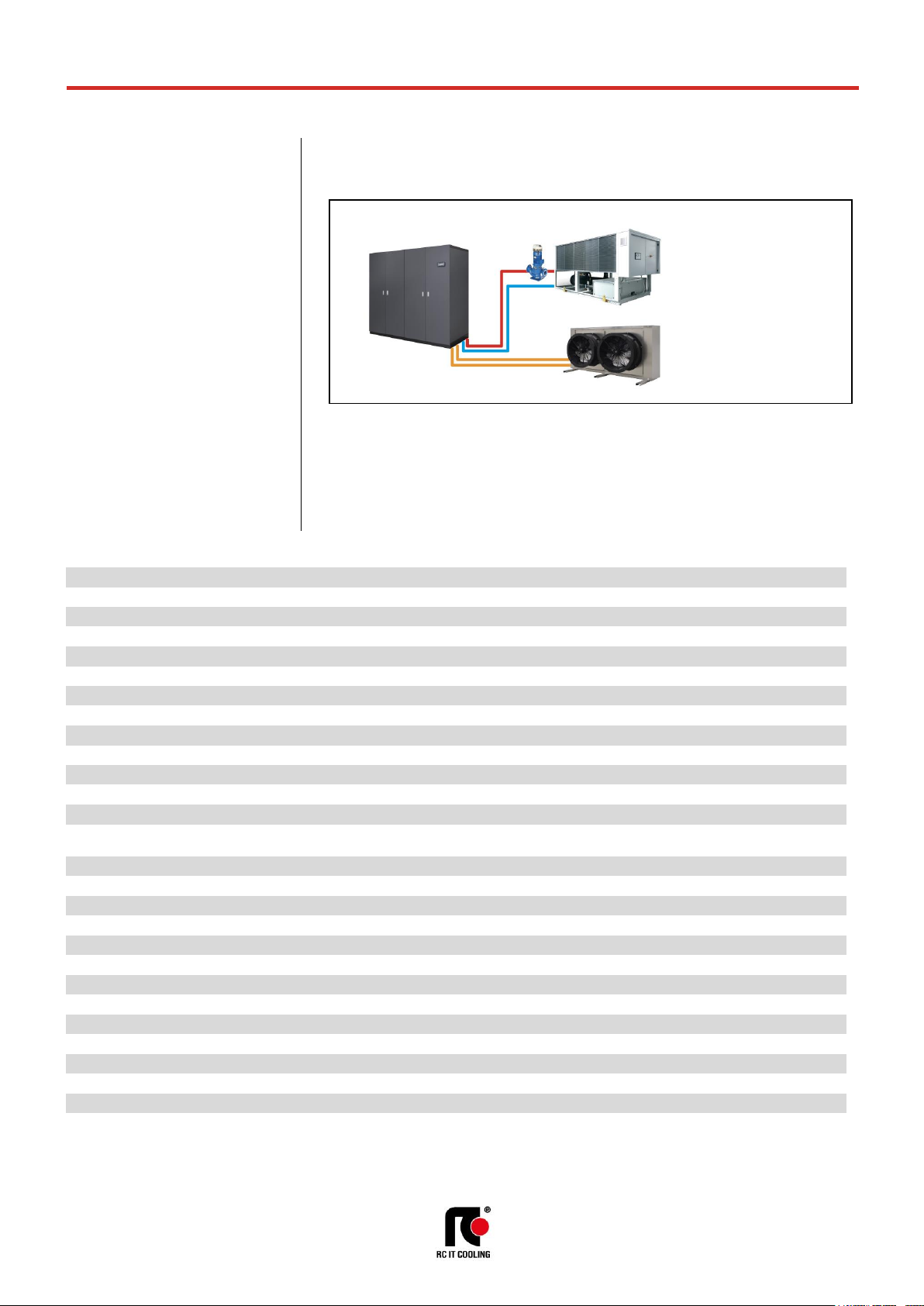
DUAL FLUID SYSTEM
DUAL FLUID system on the machine allows to obtain two independent cooling systems:
• Chilled water coil
• Direct expansion coil
The microprocessor control system automatically manages the system, by activating the cooling circuit
more convenient according to the parameters set.
With this system, it is possible, with a limited use of space, to solve several plant problems such as:
• Chilled water coil fed with chilled water or mains water as a stand-by of the main cooling
circuit.
• Double chilled water feeding with two independent circuit. This solution is used when you
need to ensure redundancy of the cooling system.
The temperature control is performed with the same logic of the main coil.
TECHNICAL DATA
VERSION (1)
U / O
U / O
U / O
U / O
U / O
MODEL 011 P1 S
014 P1 S
016 P1 S
020 P1 S
022 P1 S
SIZE E1
E2
E2
E3
E3
COOLING CAPACITY (2)
Total
kW
12,2
17,8
18,4
25,4
26,5
Sensible
kW
11,8
17,2
18
24,6
25,6
SHR (3) 0,97
0,97
0,98
0,97
0,97
COOLING COIL
Water flow rate (2)
m3/h
2,12
3,06
3,16
4,35
4,57
dP coil + valve (2)
kPa
15
33,5
35,6
24,7
26,6
Water volume
l
4,2
5,3
5,3
7,8
7,8
HYDRAULIC CONNECTIONS
WATER INLET / OUTLET ISO 7/1 - R
Ø
1"
1"
1"
1+1/4"
1+1/4"
VERSION (1)
U / O
U / O
U / O
U / O
U / O
MODEL 026 P1 S
032 P1 S
037 P1 S
041 P1 S
045 P1 S
SIZE E3
E4
E4
E4
E4
COOLING CAPACITY (2)
Total
kW
27,4
39
43,4
46
46
Sensible
kW
26,8
38,3
42
44,9
44,9
SHR (3) 0,98
0,98
0,97
0,98
0,98
COOLING COIL
Water flow rate (2)
m3/h
4,71
6,69
7,45
7,92
7,92
dP coil + valve (2)
kPa
28,3
14,2
17,1
19
19
Water volume
l
7,8
13,8
13,8
13,8
13,8
HYDRAULIC CONNECTIONS
WATER INLET / OUTLET ISO 7/1 - R
Ø
1+1/4"
1+1/2"
1+1/2"
1+1/2"
1+1/2"
THE COOLING CAPACITY DOES NOT CONSIDER THE SUPPLY FAN MOTOR THERMAL LOAD
1. U = Under, downflow / O = Over, upflow
2. Characteristics referred to entering air at 26°C-40%RH with chilled water temperature 7-12°C - 0% glycol
3. SHR = Sensible cooling capacity / Total cooling capacity.
Air conditioner
Remote
condenser
Liquid chiller
Page 19
t-NEXT DF DX
T_tNEXTDFDX_0719_EN
19
MEHITS S.p.A.
DATA BOOK
TECHNICAL DATA
VERSION (1)
U / O
U / O
U / O
U / O
U / O
MODEL 039 P2 D
048 P2 D
055 P2 D
062 P2 D
075 P2 D
SIZE E5
E5
E6
E6
E7
COOLING CAPACITY (2)
Total
kW
48,8
55,5
65,3
67,3
101
Sensible
kW
48,8
55,2
63,2
65,4
95,3
SHR (3) 1
0,99
0,97
0,97
0,94
COOLING COIL
Water flow rate (2)
m3/h
8,38
9,54
11,23
11,59
17,42
dP coil + valve (2)
kPa
26,3
33,1
15,7
16,6
38,8
Water volume
l
18,1
18,1
18,1
18,1
24,6
HYDRAULIC CONNECTIONS
WATER INLET / OUTLET ISO 7/1 - R
Ø
2"
2"
2"
2"
2+1/2"
VERSION (1)
U / O
U / O
U / O U U
MODEL 082 P2 D
092 P2 D
102 P2 D
117 P4 D
146 P4 D
SIZE E7
E8
E8
E9
E9
COOLING CAPACITY (2)
Total
kW
101
116
116
136
136
Sensible
kW
95,3
108
108
136
136
SHR (3) 0,94
0,93
0,93 1 1
COOLING COIL
Water flow rate (2)
m3/h
17,42
19,9
19,9
23,43
23,43
dP coil + valve (2)
kPa
38,8
49,3
49,3
39,9
39,9
Water volume
l
24,6
28,5
28,5
33,8
33,8
HYDRAULIC CONNECTIONS
WATER INLET / OUTLET ISO 7/1 - R
Ø
2+1/2"
2+1/2"
2+1/2"
3”
3”
THE COOLING CAPACITY DOES NOT CONSIDER THE SUPPLY FAN MOTOR THERMAL LOAD
1. U = Under, downflow / O = Over, upflow
2. Characteristics referred to entering air at 26°C-40%RH with chilled water temperature 7-12°C - 0% glycol
3. SHR = Sensible cooling capacity / Total cooling capacity.
2-WAY BALL VALVE FOR CHILLED WATER FLOW CONTROL
The water flow control in the finned coil is acieved through a 2-way modulating ball valve with equal
percentage flow control ensured by the integrated characterizing disc.
This type of valve offers the following series of benefits:
• Equal percentage flow control.
• No peaks initial flow.
• Excellent stability control thanks to the integrated characterizing disc.
• Excellent characteristic in partialisation.
• Stability in control.
• Maintenance free.
• Self-cleaning.
CHARACTERISTICS OF THE 2-WAY BALL VALVE
• Closing seal with leakage rate in Class A (EN 12266-1)
• Maximum fluid pressure Ps=1600kPa
• Maximum closing pressure (Close-off) ∆Ps=1400kPa
The rotative actuator is controlled by a signal 0 … 10VDC from the microprocessor controller. The
actuator is equipped with an emergency button for manual operation and is maintenance-free.
Page 20
t-NEXT DF DX
T_tNEXTDFDX_0719_EN
20
MEHITS S.p.A.
DATA BOOK
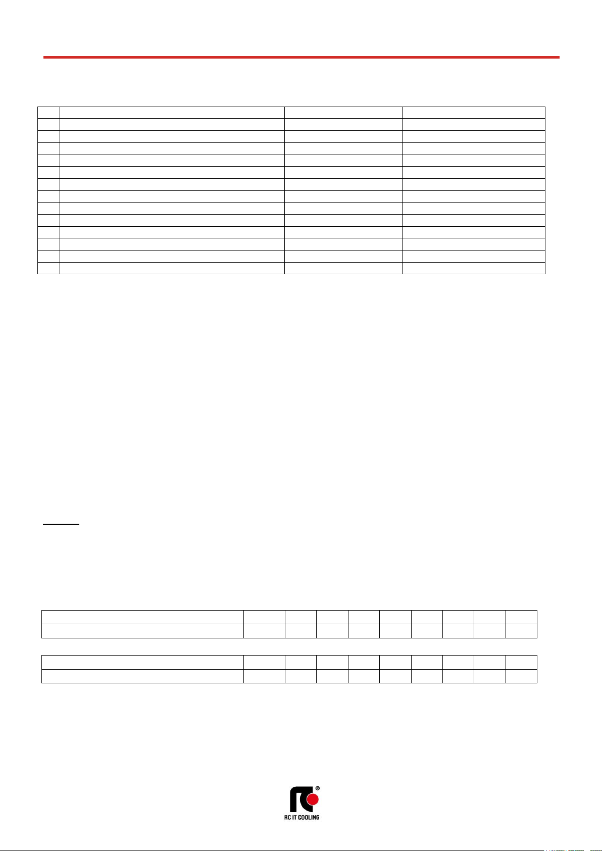
WATER QUALITY OF THE HYDRAULIC CIRCUITS
The values shown in the table must be guaranteed during the entire life cycle of the machine.
Description
Symbol
Range 1 Hydrogen Ions
pH
7.5 ÷ 9
2
Presence of calcium (Ca) and magnesium (Mg)
Hardness
4 ÷ 8.5 °D
3
Chlorine ions
Cl-
< 150 ppm
4
Iron Ions
Fe3+
< 0.5 ppm 5 Manganese Ions
Mn2+
< 0.05 ppm 6 Carbon dioxide
CO2
< 10 ppm
7
Hydrogen sulphide
H2S
< 50 ppb
8
Oxygen
O2
< 0.1 ppm 9 Chlorine
Cl2
< 0.5 ppm
10
Ammonia
NH3
< 0.5 ppm
11
Ratio between carbonates and sulphates
HCO3-/SO
4
2-
> 1
12
Sulphate ions
SO
4
--
< 100 ppm
13
Phosphate ions
PO
4
3-
< 2.0 ppm
where: 1/1.78°D = 1°Fr with 1°Fr = 10 gr CaCO3 / m3
ppm = parts for millions
ppb = part for billion
Explanatory notes:
ref.1: A greater concentration of hydrogen ions (pH) than 9 implies a high risk of deposits, whereas a lower pH than 7 implies a high risk of
corrosion.
ref.2: The hardness measures the amount of Ca and Mg carbonate dissolved in the water with a temperature lower than 100°C (temporary
hardness). A high hardness implies a high risk of deposits.
ref.3: The concentration of chloride ions with higher values than those indicated causes corrosion.
ref. 4 - 5 - 8: The presence of iron and manganese ions and oxygen leads to corrosion.
ref.6 - 7: Carbon dioxide and hydrogen sulphide are impurities that promote corrosion.
ref.9: Usually in water from the waterworks it is a value of between 0.2 and 0.3 ppm. High values cause corrosion.
ref.10: The presence of ammonia reinforces the oxidising power of oxygen
ref.11: Below the value shown in the table, there is a risk of corrosion due to the trigger of galvanic currents between copper and other less noble
metals.
ref.12: The presence of sulphates ions triggers corrosion phenomenon.
ref.13: The presence of phosphates ions triggers corrosion phenomenon.
It is necessary to carry out periodic checks, with withdrawals at different points of the hydraulic system. During the first year of operation, checks are
recommended every 4 months which can be reduced every 6 months starting from the second year of operation.
WARNING:
It is necessary that, in the presence of dirty and / or aggressive waters, an intermediate heat exchanger is installed upstream of the heat
exchangers
ANTIFREEZE MIXTURES
In plants that are not adequately protected by heating cables, protect the hydraulic circuit with an anti-freeze mixture when the ambient air temperature can
drop below 5°C.
The values are indicative and may significantly vary depending on the glycol manufacturer. Refer to your glycol supplier for detail.
The values consider a precautionary difference of 5°C between the minimum ambient air temperature and the freezing temperature of the mixture.
In the hydraulic circuit do not send fluids other than water or mixtures with ethylene / propylene glycol.
If other products are provided, in addition to mixtures of water and ethylene or propylene glycol, contact the Manufacturer to check the compatibility with the
machine components.
Minimum ambient air temperature
°C 5 0
-5
-10
-15
-20
-25
-30
ETHYLENE GLYCOL (suggested % in weight)
% 0 12
20
30
35
40
45
50
Minimum ambient air temperature
°C 5 2
-3
-9
-13
-17
-23
-29
PROPYLENE GLYCOL (suggested % in weight)
% 0 10
20
30
35
40
45
50
Page 21

t-NEXT DF DX
T_tNEXTDFDX_0719_EN
21
MEHITS S.p.A.
DATA BOOK
REFRIGERANT CHARGE
The air conditioner is supplied with a minimum R410A refrigerant charge. Refrigerant must be charged. The following table shows the refrigerant charge that
must be introduced for the air conditioner only. Remote condenser, connections pipes and optional are excluded.
VERSION (1)
U / O
U / O
U / O
U / O
U / O
MODEL 011 P1 S
014 P1 S
016 P1 S
020 P1 S
022 P1 S
SIZE E1
E2
E2
E3
E3
REFRIGERANT
R410A
R410A
R410A
R410A
R410A
Refrigerant circuits x Refrigerant charge (2)
n x kg
1 x 3,2
1 x 3,4
1 x 3,4
1 x 4,0
1 x 4,0
HFC R410A - F Gas - CO2 equivalent
t
6,68
7,10
7,10
8,35
8,35
VERSION (1)
U / O
U / O
U / O
U / O
U / O
MODEL 026 P1 S
032 P1 S
037 P1 S
041 P1 S
045 P1 S
SIZE E3
E4
E4
E4
E4
REFRIGERANT
R410A
R410A
R410A
R410A
R410A
Refrigerant circuits x Refrigerant charge (2)
n x kg
1 x 4,0
1 x 5,7
1 x 5,7
1 x 8,6
1 x 8,6
HFC R410A - F Gas - CO2 equivalent
t
8,35
11,90
11,90
17,96
17,96
VERSION (1)
U / O
U / O
U / O
U / O
U / O
MODEL 039 P2 D
048 P2 D
055 P2 D
062 P2 D
075 P2 D
SIZE E5
E5
E6
E6
E7
REFRIGERANT
R410A
R410A
R410A
R410A
R410A
Refrigerant circuits x Refrigerant charge (2)
n x kg
2 x 4,5
2 x 4,5
2 x 4,9
2 x 4,9
2 x 8,1
HFC R410A - F Gas - CO2 equivalent
t
18,79
18,79
20,46
20,46
33,83
VERSION (1)
U / O
U / O
U / O U U
MODEL 082 P2 D
092 P2 D
102 P2 D
117 P4 D
146 P4 D
SIZE E7
E8
E8
E9
E9
REFRIGERANT
R410A
R410A
R410A
R410A
R410A
Refrigerant circuits x Refrigerant charge (2)
n x kg
2 x 8,1
2 x 8,7
2 x 8,7
2 x 10,8
2 x 10,8
HFC R410A - F Gas - CO2 equivalent
t
33,83
36,33
36,33
45,1
45,1
1. U = Under, downflow / O = Over, upflow
2. Refrigerant charge required for the air conditioner only operation. Remote condenser, connections pipes and optional are excluded.
For air conditioners with double refrigerant circuit is indicated the number of circuits x the charge of a single circuit.
Page 22
t-NEXT DF DX
T_tNEXTDFDX_0719_EN
22
MEHITS S.p.A.
DATA BOOK
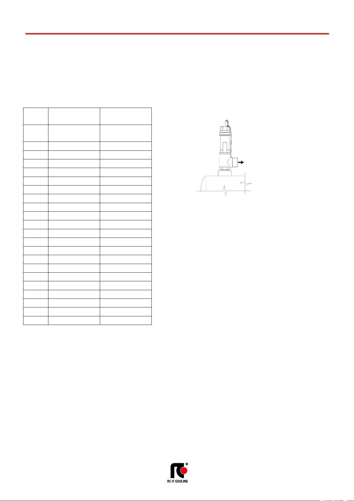
PRESSURE RELIEF VALVE
The pressure relief valve of the refrigerant circuit is installed in the machines when required by Directive 2014/68/EU.
The valve is installed on liquid receiver of each refrigerant circuit of the machine with the purpose to protect the circuit from overpressure.
It is up to the installer to check whether the system complies with the 2014/68 / EU standard regarding the installation of the pressure relief valve.
By plant we mean the complete system that includes the internal machine, the remote condenser and the connecting pipes
The installer must calculate the amount of refrigerant contained in the system and, if the refrigerant charge is higher than 10 kg, he must install the pressure
relief valve.
Factory installed
components
At Installer care
Pressure relief valve on
liquid receiver
Possible pressure relief
valve
Model
[bar]
[bar]
011 P1 S
---
41,5
014 P1 S
---
41,5
016 P1 S
---
41,5
020 P1 S
---
45,0
022 P1 S
---
45,0
026 P1 S
---
45,0
032 P1 S
---
45,0
037 P1 S
---
45,0
041 P1 S
45,0
---
045 P1 S
45,0
---
039 P2 D
---
45,0
048 P2 D
---
45,0
055 P2 D
---
45,0
062 P2 D
---
45,0
075 P2 D
45,0
---
082 P2 D
45,0
---
092 P2 D
45,0
---
102 P2 D
45,0
---
117 P4 D
45,0
---
146 P4 D
45,0
---
Exhaust flow
CONNECTION Ø 3/4” G – M
Page 23
t-NEXT DF DX
T_tNEXTDFDX_0719_EN
23
MEHITS S.p.A.
DATA BOOK
R1
EVP
RU
C1
SPH1
BPH1
BPL1
IP
FG
VE
IP
FG
VE1
T1
RL
VS
CND1
RU
RU
RU
M1
DF
T2
Tin
R1
EVP
RU
C1
SPH1
BPH1
BPL1
IP
FG
VE
IP
FG
VE1
T1
RL
VS
CND1
RU
RU
RU
M1
DF
T2
Tin
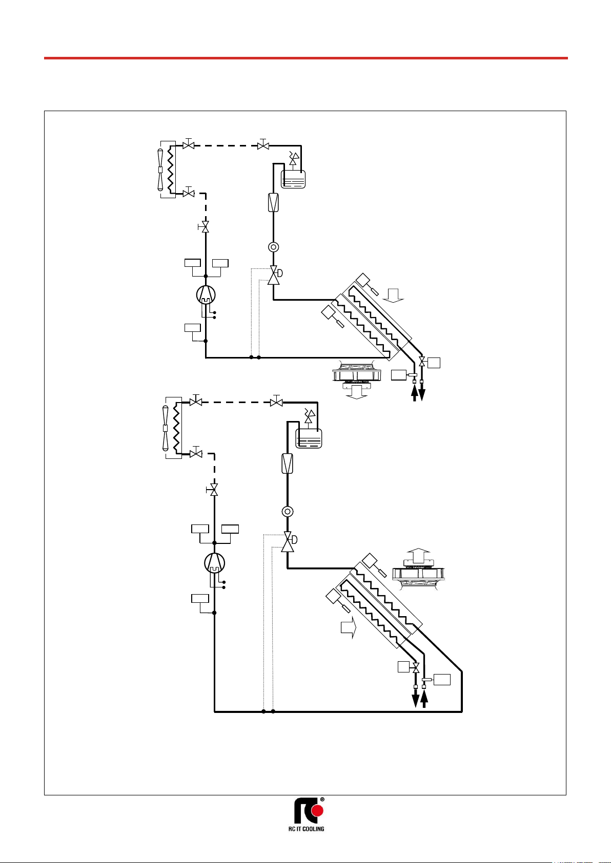
REFRIGERANT CIRCUIT
Below refrigerant diagrams for version with single or double refrigerant circuit. The diagrams refer to the standard configuration, without optional.
UNDER - SINGLE REFRIGERANT CIRCUIT
OVER - SINGLE REFRIGERANT CIRCUIT
LEGENDA
C1 Compressor
R1 Crankcase heater
CND Condenser.
EVP Evaporator
EC Dual fluid
Chilled water coil
BPH High pressure transducer.
BPL Low pressure transducer.
SPH High pressure switch
M1 Dual-Fluid 2-way valve
VS Pressure relief valve.
FG Refrigerant filter.
IP Sight glass.
VE Expansion valve.
T Temperature probes.
RU Valves
RL Liquid receiver
VS = Pressure relief valve
Only models 041 P1, 045 P1
VS = Pressure relief valve
Only models 041 P1, 045 P1
Page 24

t-NEXT DF DX
T_tNEXTDFDX_0719_EN
24
MEHITS S.p.A.
DATA BOOK
R1
R2
IP
EVP
FG
RU
VE
C1
SPH1
BPH1
BPL1
VS
C2
SPH2
BPH2
BPL2
IP
FG
VE2
IP
FG
RU
VE
IP
FG
VE1
RL
RL
VS
CND1
RU
RU
CND2
RU
RU
RU
RU
T1
M1
DF
T2
Tin
R1
R2
IP
EVP
FG
RU
VE
C1
SPH1
BPH1
BPL1
VS
C2
SPH2
BPH2
BPL2
IP
FG
VE2
IP
FG
RU
VE
IP
FG
VE1
T1
RL
RL
VS
CND1
RU
RU
CND2
RU
RU
RU
RU
M1
DF
T2
Tin
R2
R1
C2
C1
R2
R1
C2
C1
UNDER - DOUBLE REFRIGERANT CIRCUIT
OVER - DOUBLE REFRIGERANT CIRCUIT
LEGENDA
C1 Compressor
R1 Crankcase heater
CND Condenser.
EVP Evaporator
EC Dual fluid
Chilled water coil
BPH High pressure transducer.
BPL Low pressure transducer.
SPH High pressure switch
M1 Dual-Fluid 2-way valve
VS Pressure relief valve.
FG Refrigerant filter.
IP Sight glass.
VE Expansion valve.
T Temperature probes.
RU Valves
RL Liquid receiver
VS = Pressure relief valve
Only models 075 P2, 082 P2,
092 P2, 102 P2, 117 P4, 146 P4
VS = Pressure relief valve
Only models 075 P2, 082 P2,
092 P2, 102 P2
SIZE E9
Page 25
t-NEXT DF DX
T_tNEXTDFDX_0719_EN
25
MEHITS S.p.A.
DATA BOOK
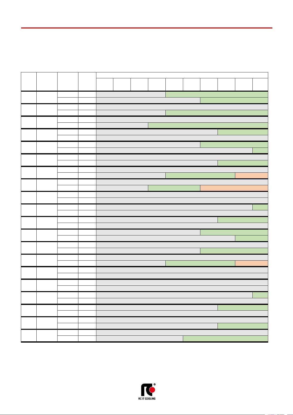
RECOMMENDED REFRIGERANT LINES
Values are referred to “EQUIVALENT LENGTH” of the piping.
You are kindly requested to always refer to the “INSTALLATION DIAGRAM” for the allowable height difference and to properly select all necessary
components. Verify the need to use pressure limiting devices (pressure relief valves) where not already provided for by Directive 2014/68 / EU.
In some cases, the diameter of the refrigerant lines may not correspond with the diameter of the cooling taps.
This is completely normal. It is enough to provide a reduction fitting to adjust the diameter.
Model
Capacity
for single
circuit
[kW]
Line
Nominal
Ø [mm]
EQUIVALENT LENGHT [m] FOR ON / OFF COMPRESSORS R410A
5
10
15
20
25
30
35
40
45
50
011
P1 S
11
Gas
12
12 mm
16 mm
Liquid
12
12 mm
16 mm
014
P1 S
14
Gas
16
16 mm
Liquid
12
12 mm
16 mm
016
P1 S
16
Gas
16
16 mm
Liquid
12
12 mm
16 mm
020
P1 S
20
Gas
16
16 mm
18 mm
Liquid
16
16 mm
022
P1 S
22
Gas
16
16 mm
18 mm
Liquid
16
16 mm
18 mm
026
P1 S
26
Gas
22
22 mm
Liquid
16
16 mm
18 mm
032
P1 S
32
Gas
22
22 mm
Liquid
16
16 mm
18 mm
22 mm
037
P1 S
37
Gas
22
22 mm
Liquid
16
16 mm
18 mm
22 mm
041
P1 S
41
Gas
22
22 mm
Liquid
22
22 mm
045
P1 S
45
Gas
22
22 mm
28 mm
Liquid
22
22 mm
039
P2 D
19,5
Gas
16
16 mm
18 mm
Liquid
16
16 mm
048
P2 D
24
Gas
16
16 mm
18 mm
Liquid
16
16 mm
18 mm
055
P2 D
27,5
Gas
22
22 mm
Liquid
16
16 mm
18 mm
062
P2 D
31
Gas
22
22 mm
Liquid
16
16 mm
18 mm
22 mm
075
P2 D
37,5
Gas
22
22 mm
Liquid
22
22 mm
082
P2 D
41
Gas
22
22 mm
Liquid
22
22 mm
092
P2 D
46
Gas
22
22 mm
28 mm
Liquid
22
22 mm
102
P2 D
51
Gas
22
22 mm
28 mm
Liquid
22
22 mm
117
P4 D
58,5
Gas
28
28 mm
Liquid
22
22 mm
28 mm
146
P4 D
73
Gas
28
28 mm
Liquid
22
22 mm
28 mm
For equivalent lengths over 50m, please contact the Manufacturer's Sales Office.
Page 26
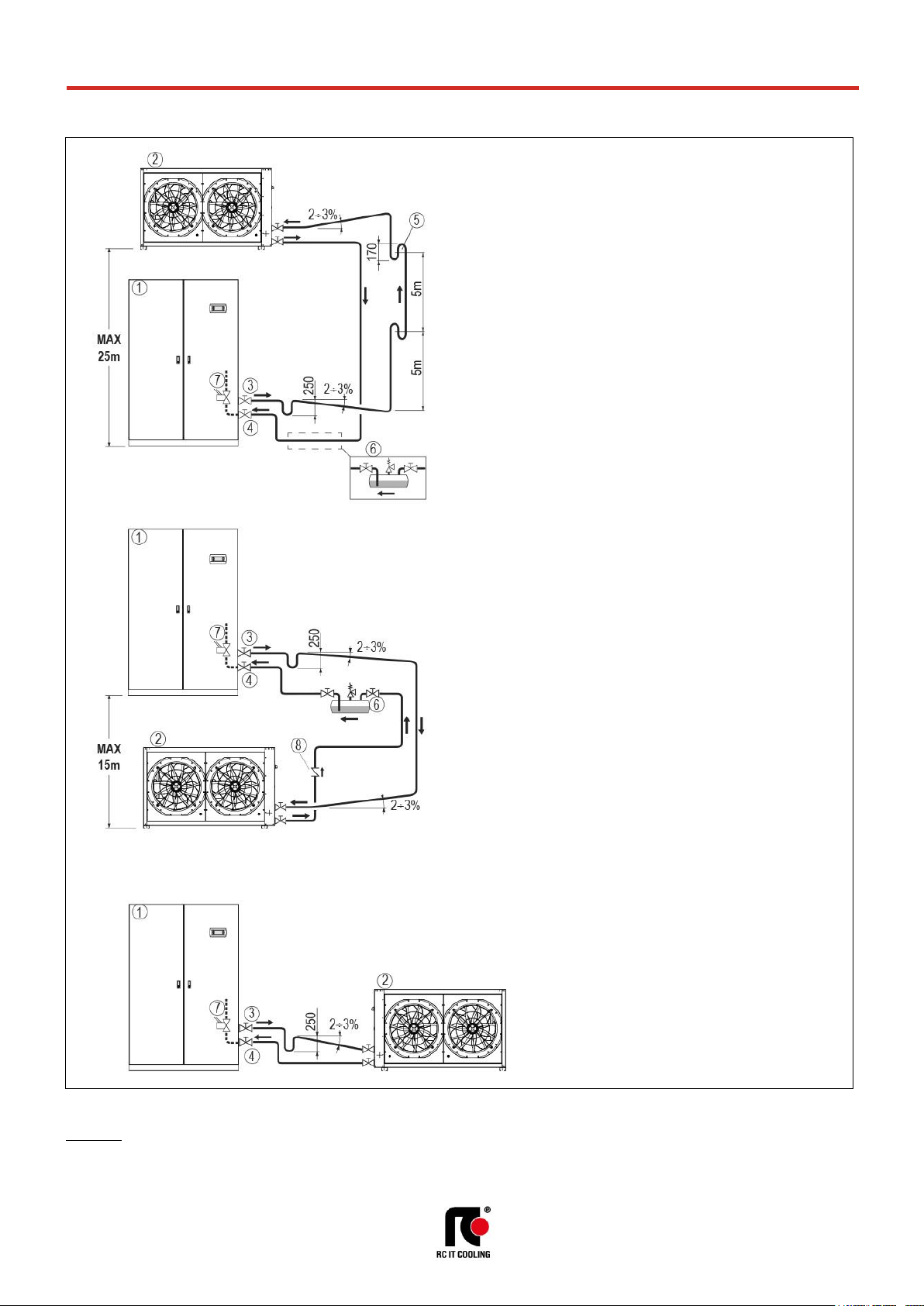
t-NEXT DF DX
T_tNEXTDFDX_0719_EN
26
MEHITS S.p.A.
DATA BOOK
INSTALLATION DIAGRAM
WARNING
It is necessary to provide the refrigerant charge for the connection pipes and for the remote air-cooled condenser.
Charge refrigerant in the suitable quantity and lubricant oil in 10% ratio of charged refrigerant.
Lubricant oil must be the same type as the charged one as shown on the compressor plate.
CARRY OUT PIPING WITH SLOPES INDICATED TO FAVOR THE
RETURN OF THE LUBRICANT OIL TO THE COMPRESSOR
APPLY THE DIAGRAM TO ANY REFRIGERANT CIRCUIT OF THE
MACHINE.
Difference in height between the machine and the remote
condenser: Value expressed in equivalent length
LEGENDA
1. Air conditioner
2. Remote air-cooled condenser
3. Gas discharge line
4. Liquid return line
5. Trap. Foresee a trap every 5m of the rising pipe.
6. Additional liquid receiver, external to the machine –
By the installer.
It is suggested for:
- Plants with refrigerant lines with an equivalent length of more
than 25 meters
- Plants with refrigerant lines of any length and operating at
outdoor temperatures below 0°C.
7. “601 Solenoid valve on liquid line”. Optional accessory of the
machine, suggested for plants with refrigerant pipe longer than 10m.
8. Check valve – By the Installer. The valve must be installed on the
liquid line close to the condenser. The valve prevents the return of
liquid in the condenser, particularly in the case of plant shutdown
during the winter season.
Page 27

t-NEXT DF DX
T_tNEXTDFDX_0719_EN
27
MEHITS S.p.A.
DATA BOOK
ACOUSTIC DATA
Acoustic data of the standard machine at full load working conditions.
WARNING:
In a closed room the noise produced by a sound source reaches the listener in two different ways:
• Directly
• Reflected from the surrounding walls, floor, ceiling, from furniture.
With the same sound source, the noise produced in a closed room is greater than that produced
outdoors. In fact, the sound pressure level generated by the source, must be added to the one reflected
from the room. Also, the shape of the room affects the sound.
MODEL
011 P1 S
014 P1 S
016 P1 S
020 P1 S
022 P1 S
026 P1 S
SIZE E1
E2
E2
E3
E3
E3
SOUND LEVEL ISO 3744 (1)
On air delivery, Under
dB(A)
64,7
70,8
71,9
70,3
71,8
72,8
On air intake, Under
dB(A)
55,9
56,9
58,1
57,0
58,9
59,2
On front side, Under
dB(A)
47
48
49
48
50
50
On air delivery, Over
dB(A)
64,7
70,8
71,9
70,3
71,8
72,8
On air intake, Over (2)
dB(A)
52
54
55
55
59
57
On front side, Over (3)
dB(A)
41,8
47,1
48,1
46,7
48,7
49,0
MODEL
032 P1 S
037 P1 S
041 P1 S
045 P1 S
039 P2 D
048 P2 D
SIZE E4
E4
E4
E4
E5
E5
SOUND LEVEL ISO 3744 (1)
On air delivery, Under
dB(A)
78,1
81,1
78,9
78,9
81,3
81,5
On air intake, Under
dB(A)
64,2
67,1
66,4
66,4
67,3
69,0
On front side, Under
dB(A)
55
58
57
57
58
60
On air delivery, Over
dB(A)
78,1
81,1
78,9
78,9
81,3
81,5
On air intake, Over (2)
dB(A)
61
63
62
62
63
64
On front side, Over (3)
dB(A)
54,3
57,3
56,8
56,8
57,6
59,4
MODEL
055 P2 D
062 P2 D
075 P2 D
082 P2 D
092 P2 D
102 P2 D
SIZE E6
E6
E7
E7
E8
E8
SOUND LEVEL ISO 3744 (1)
On air delivery, Under
dB(A)
77,9
78,7
80,1
80,1
82,5
82,5
On air intake, Under
dB(A)
64,1
65,0
67,8
67,8
70,1
70,1
On front side, Under
dB(A)
55
56
58
58
61
61
On air delivery, Over
dB(A)
77,9
78,7
80,1
80,1
82,5
82,5
On air intake, Over (2)
dB(A)
61
62
64
64
66
67
On front side, Over (3)
dB(A)
54,1
55,0
58,1
58,1
60,4
60,4
MODEL
117 P4 D
146 P4 D
SIZE E9
E9
SOUND LEVEL ISO 3744 (1)
On air delivery, Under
dB(A)
83,4
83,4
On air intake, Under
dB(A)
70,9
70,9
On front side, Under
dB(A)
62
62
On air delivery, Over
dB(A)
--
--
On air intake, Over (2)
dB(A)
--
--
On front side, Over (3)
dB(A)
--
--
1. Noise pressure level at 1 meter in free field – ISO 3744
2. Air intake from the front
3. Air intake from the bottom
Page 28

t-NEXT DF DX
T_tNEXTDFDX_0719_EN
28
MEHITS S.p.A.
DATA BOOK
ELECTRICAL DATA
Electrical data of the system at full load working conditions.
VERSION (1)
U / O
U / O
U / O
U / O
U / O
MODEL 011 P1 S
014 P1 S
016 P1 S
020 P1 S
022 P1 S
SIZE E1
E2
E2
E3
E3
Power supply
V/ph/Hz
400/3+N/50
400/3+N/50
400/3+N/50
400/3+N/50
400/3+N/50
Maximum current input (FLA)
A
7,65
10,0
11,5
15,2
19,2
VERSION (1)
U / O
U / O
U / O
U / O
U / O
MODEL 026 P1 S
032 P1 S
037 P1 S
041 P1 S
045 P1 S
SIZE E3
E4
E4
E4
E4
Power supply
V/ph/Hz
400/3+N/50
400/3+N/50
400/3+N/50
400/3+N/50
400/3+N/50
Maximum current input (FLA)
A
20,4
22,4
25,8
29,4
35,4
VERSION (1)
U / O
U / O
U / O
U / O
U / O
MODEL 039 P2 D
048 P2 D
055 P2 D
062 P2 D
075 P2 D
SIZE E5
E5
E6
E6
E7
Power supply
V/ph/Hz
400/3+N/50
400/3+N/50
400/3+N/50
400/3+N/50
400/3+N/50
Maximum current input (FLA)
A
26,2
34,4
40,8
44,8
52,1
VERSION (1)
U / O
U / O
U / O U U
MODEL 082 P2 D
092 P2 D
102 P2 D
117 P4 D
146 P4 D
SIZE E7
E8
E8
E9
E9
Power supply
V/ph/Hz
400/3+N/50
400/3+N/50
400/3+N/50
400/3+N/50
400/3+N/50
Maximum current input (FLA)
A
58,9
70,9
76,9
86,1
113,0
1. U = Under, downflow / O = Over, upflow
WARNING:
The electric data indicated refer only to the indoor unit.
Optional accessory electric data are included within the dedicated chapters and must be added.
Please refer to ELCA WORLD selection program to calculate the electrical data of the air conditioner according to the requested optional
accessories.
The remote air-cooled condenser is not included because it has independent power supply.
Page 29

t-NEXT DF DX
T_tNEXTDFDX_0719_EN
29
MEHITS S.p.A.
DATA BOOK
MICROPROCESSOR CONTROL SYSTEM
The unit is equipped with the controller connected to a 6 keys keyboard with graphic display on which all
information in English language or easily identifiable symbols are displayed.
The controller disposes of a “flash” memory that preserves the information even in absence of power
supply. Part of memory is dedicated to the registration of intervened events - up to 200 events.
DISPLAY – KEYBOARD FUNCTIONS
DISPLAY - MAIN MASK
The main mask shows time, date, room temperature and humidity values (if the relative probe is
present) and areas for displaying operating and alarm status with dedicated icons:
CONNECTIVITY
Through the optional serial port, the microprocessor control enables communication with the modern
buildings BMS systems with the following protocols: MODBUS; LON; BACNET MS/TP RS485; BACNET
OVER IP.
PASSWORD
Level 1: On request of the End User. Allowing to reach USER menu
Level 2: Asks to Service: Allowing to reach SERVICE menu
Level 3: Asks to Service: Allowing to reach FACTORY menu
No passwords request to enter: UNIT, SETPOINT, IN/OUT, CLOCK, HISTORY menu
ALARM
Alarm presence with red light.
Push for alarm description.
In case of more alarms scroll by UP / DOWN.
PRG
Menu list, scrolled by UP/DOWN:
Unit; Set-point; In/Out; Clock; History; User; Service;
Factory. ENTER to execute.
ESC
Home. Used to come back to the previous menu level or to the
main screen.
UP
DOWN
Changes pages and values of sets.
By pressing in HOME mask, the synoptic of the main controls is
displayed.
ENTER
Moving the cursor on adjustable Program(s) fields to confirm
the changes.
Press ENTER to get out the fields.
Controller
Keyboard and Display
Y Y D
D
Area 1: Status of the unit: on / off
Area 2: Status detail
Area 3: Type of event (only in case of an event)
Area 3_A: Code and type of event
Area 4: Active cooling devices
Area 5: Active free-cooling devices
Area 6: Active humidity devices
Area 7: Active heating devices
Area 8: on / off parameters
Area 9: BMS address
Area 10: LAN address
Area 11: Schematic representation of units
Area 12: Active function presence icon
Page 30

t-NEXT DF DX
T_tNEXTDFDX_0719_EN
30
MEHITS S.p.A.
DATA BOOK
LAN NETWORK
The LAN is part of the control software and it is possible to connect up to 10 units.
This type of connection allows to control the units in coherent way, moreover the units can be controlled
and managed from a shared remote terminal.
LAN ADDRESS LIST
Unit # 1 2 3 4 5 6 7 8 9 10
Remote Terminal
Mother board address
1 2 3 4 5 6 7 8 9
10
--
Terminal address
11
12
13
14
15
16
17
18
19
20
32
The unit connection to the local network (LAN) allows to perform the following functions:
• Balancing the operating hours among the different units by rotating the reserve units (Stand-by)
• Turning on the reserve units in case other units should turn off due to an alarm, maintenance or
power feed interruption
• Turning on reserve units to offset the excessive thermal load
• Checking up to 10 units with a single user terminal (shared user terminal)
Humidifier
control
Network
analyser
T Probe
T/H probe
Additional T/H
probe
Expansion
board 1
Expansion
board 2
Expansion
board 3
EEV 1
controller
EEV 2
controller
Fan 2 Fan 3 Fan
1
Controller
backup module
MODBUS
BACnet
OVER IP
LON
BACnet
MS/TP RS485
BMS 1
Display & Keyboard
LAN address=11
Controller - LAN address=1
FieldBus2
LAN address=2
LAN address=12
UNIT 2
LAN address=3
LAN address=13
UNIT 3
LAN address=10
LAN address=20
UNIT 10
LAN address=32
REMOTE
TERMINAL
UNIT 1
LAN
Diagram in maximum configuration
Page 31

t-NEXT DF DX
T_tNEXTDFDX_0719_EN
31
MEHITS S.p.A.
DATA BOOK
DEMAND LIMIT
Demand Limit function is part of the control software for machines with double refrigerant circuit. It
allows to limit the absorbed current of the machine.
The function must be activated and configurated. A digital inlet on electrical panel connecting
terminals allows the remote enabling of the function with an external signal without tension.
The software allows to select the resources to disable (compressors, electric heaters,…).
TEMPERATURE PROBE ON AIR RETURN / DELIVERY
Temperature probe installed on the air return and delivery.
Temperature control and regulation function on air return.
CLOGGED FILTERS SENSOR
The system includes a differential pressure switch installed in the electrical panel or in the front of the
indoor unit and the plastic hoses for the relief of the pressure upstream and downstream the air filters.
Control range: 0.3 … 4.0 mbar (30 … 400 Pa)
Differential for intervention: 0.15 mbar (15 Pa)
FLOOD SENSOR
The system includes an electronic relay installed in the electrical panel of the machine and a water
detector.
The electrical connections for the probe and the alarm contact are present in the machine's terminal
board.
Sensor is supplied to be connected and installed at customer care.
Page 32

t-NEXT DF DX
T_tNEXTDFDX_0719_EN
32
MEHITS S.p.A.
DATA BOOK
80
250
70
70 70
A
125
130
70 A 70
POSSIBLE AIR INTAKE FOR OVER VERSIONS
OVER VERSION - AIR INTAKE FROM THE BOTTOM
Thanks to the particular basement design, it is possible to have the unit air intake from the bottom side.
With this solution, it is necessary to foresee the optional blind frontal panels
OVER VERSION - AIR INTAKE FROM THE BACK SIDE
(Sizes E4, E5, E6, E7, E8, E9 excluded)
It is possible to have the unit air intake from the back side.
Due to the limited size of the air intake, the air flow is limited to the 20% of the nominal one.
The air intake must be made by Customer during installation.
In case the air intake is used for fresh air, it is necessary the temperature / humidity probe reposition in
front of the heat exchanger, to allow for optimum reading of the values of temperature / humidity.
The electric cable of the probe has enough length for the repositioning.
GRANDEZZA
E1
E2
E3
A
mm
510
645
945
Max air flow
m3/h
600
1000
1500
AIR INTAKE FROM THE BACK SIDE
Back side view
OVER
E1 – E2 – E3
Page 33

t-NEXT DF DX
T_tNEXTDFDX_0719_EN
33
MEHITS S.p.A.
DATA BOOK
REMOTE AIR-COOLED CONDENSER
Remote air-cooled condensers for matching to air conditioners for IT Cooling.
The constructive solutions allow high application flexibility.
Horizontal air flow, from coil to fan.
The series has an independent power supply from the indoor unit.
Among the indoor unit and the condenser is necessary the refrigerant connection and electrical
connection of the condensing proportional control signal and the alarms.
Is available the optional “P191 power supply for condenser” from the indoor machine electrical board.
The optional includes magnetothermic switches for condenser fans.
P821 / P831 / P841 / P851 – GR-Z SERIES
The machines are made with Peraluman aluminium alloy and suitable for outdoor installation.
GR-Z A B 50: Remote condenser equipped with AC fan, microchannel condensing coil and Standard
acoustic version.
GR-Z A L 50: Remote condenser equipped with AC fan, microchannel condensing coil and Low noise
acoustic version.
GR-Z E B 50: Remote condenser equipped with EC fan, microchannel condensing coil and Standard
acoustic version.
GR-Z E L 50: Remote condenser equipped with EC fan, microchannel condensing coil and Low noise
acoustic version.
IMPORTANT
For further information about the units, please refer to “GR-Z” series Data Books.
MATCHING
REMOTE AIR-COOLED CONDENSERS FOR OUTDOOR INSTALLATION EQUIPPED WITH AC AXIAL FANS.
MODEL
011
P1 S
014
P1 S
016
P1 S
020
P1 S
022
P1 S
026
P1 S
032
P1 S
037
P1 S
041
P1 S
045
P1 S
CONDENSER
n. 1 1 1 1 1 1 1 1 1 1
GR-Z A B 50
Mod.
013
024
024
027
027
034
049
049
049
055
GR-Z A L 50
Mod.
011
018
018
025
025
036
036
043
051
051
MODEL
039
P2 D
048
P2 D
055
P2 D
062
P2 D
075
P2 D
082
P2 D
092
P2 D
102
P2 D
117
P4 D
146
P4 D
CONDENSER
n. 2 2 2 2 2 2 2 2 2 2
GR-Z A B 50
nxMod.
2x024
2x027
2x034
2x049
2x049
2x049
2x055
2x067
2x082
2x082
GR-Z A L 50
nxMod.
2x021
2x036
2x036
2x043
2x043
2x051
2x051
2x063
2x086
2x086
REMOTE AIR-COOLED CONDENSERS FOR OUTDOOR INSTALLATION EQUIPPED WITH EC AXIAL FANS.
MODEL
011
P1 S
014
P1 S
016
P1 S
020
P1 S
022
P1 S
026
P1 S
032
P1 S
037
P1 S
041
P1 S
045
P1 S
CONDENSER
n. 1 1 1 1 1 1 1 1 1 1
GR-Z E B 50
Mod.
015
024
024
027
027
034
049
049
049
055
GR-Z E L 50
Mod.
011
018
018
025
025
036
036
043
051
051
MODEL
039
P2 D
048
P2 D
055
P2 D
062
P2 D
075
P2 D
082
P2 D
092
P2 D
102
P2 D
117
P4 D
146
P4 D
CONDENSER
n. 2 2 2 2 2 2 2 2 2 2
GR-Z E B 50
nxMod.
2x024
2x027
2x034
2x049
2x049
2x049
2x055
2x067
2x082
2x082
GR-Z E L 50
nxMod.
2x021
2x036
2x036
2x043
2x043
2x051
2x051
2x063
2x086
2x086
WARNING:
Please refer to ELCA WORLD selection program to calculate the cooling capacity of the air conditioner according to the selected remote
condenser.
Page 34

t-NEXT DF DX
T_tNEXTDFDX_0719_EN
34
MEHITS S.p.A.
DATA BOOK
T-MATE DX SERIES
T-MATE DX: Remote air-cooled condensers equipped with axial fans and condensing coil with copper
tubes and aluminium fins. The machines are suitable for outdoor installation.
A Version: Equipped with AC axial fans.
E Version: Equipped with EC axial fans.
The series is available in 3 versions:
• STD - No air flow and sound level reduction.
• LNO - Air flow reduction at 85% with consequent sound level reduction.
• ELN - Air flow reduction at 70% with further sound level reduction.
T-MATE DX-PF-E: Remote air-cooled condensers equipped with EC plug fans and condensing coil with
copper tubes and aluminium fins. The machines are designed for indoor installation and ducting for air
suction and discharge. For outdoor installation, the machine must be installed under a cover or anyway
protected against atmospherics agent.
IMPORTANT
For further information about the units, please refer to “T-MATE” series Data Books.
MATCHING
REMOTE AIR-COOLED CONDENSERS FOR OUTDOOR INSTALLATION EQUIPPED WITH AC AXIAL FANS.
MODEL
011
P1 S
014
P1 S
016
P1 S
020
P1 S
022
P1 S
026
P1 S
032
P1 S
037
P1 S
041
P1 S
045
P1 S
CONDENSER
n. 1 1 1 1 1 1 1 1 1 1
T-MATE DX-A STD
Mod.
M11
M14
M17
M25
M25
M30
M35
M45
M45
M50
T-MATE DX-A LNO
Mod.
M14
M17
M25
M30
M30
M45
M45
M50
M60
M70
T-MATE DX-A ELN
Mod.
M14
M17
M25
M30
M30
M45
M45
M50
M60
M70
MODEL
039
P2 D
048
P2 D
055
P2 D
062
P2 D
075
P2 D
082
P2 D
092
P2 D
102
P2 D
117
P4 D
146
P4 D
CONDENSER
n. 2 2 2 2 2 2 2 2 2 2
T-MATE DX-A STD
nxMod.
2xM25
2xM25
2xM30
2xM35
2xM45
2xM45
2xM50
2xM60
2xM70
2xM95
T-MATE DX-A LNO
nxMod.
2xM30
2xM30
2xM45
2xM45
2xM50
2xM60
2xM70
2xM70
2xM95
2xM95
T-MATE DX-A ELN
nxMod.
2xM30
2xM30
2xM45
2xM45
2xM50
2xM60
2xM70
2xM70
2xM95
2xM110
REMOTE AIR-COOLED CONDENSERS FOR OUTDOOR INSTALLATION EQUIPPED WITH EC AXIAL FANS.
MODEL
011
P1 S
014
P1 S
016
P1 S
020
P1 S
022
P1 S
026
P1 S
032
P1 S
037
P1 S
041
P1 S
045
P1 S
CONDENSER
n. 1 1 1 1 1 1 1 1 1 1
T-MATE DX-E STD
Mod.
T11
T14
T17
T25
T25
T30
T35
T45
T45
T50
T-MATE DX-E LNO
Mod.
T14
T17
T25
T30
T30
T45
T45
T50
T60
T70
T-MATE DX-E ELN
Mod.
T14
T17
T25
T30
T30
T45
T45
T50
T60
T70
MODEL
039
P2 D
048
P2 D
055
P2 D
062
P2 D
075
P2 D
082
P2 D
092
P2 D
102
P2 D
117
P4 D
146
P4 D
CONDENSER
n. 2 2 2 2 2 2 2 2 2 2
T-MATE DX-E STD
nxMod.
2xT25
2xT25
2xT30
2xT35
2xT45
2xT45
2xT50
2xT60
2xT70
2xT95
T-MATE DX-E LNO
nxMod.
2xT30
2xT30
2xT45
2xT45
2xT50
2xT60
2xT70
2xT70
2xT95
2xT95
T-MATE DX-E ELN
nxMod.
2xT30
2xT30
2xT45
2xT45
2xT50
2xT60
2xT70
2xT70
2xT95
2xT110
REMOTE AIR-COOLED CONDENSERS FOR INDOOR INSTALLATION EQUIPPED WITH EC PLUG FANS.
MODEL
011
P1 S
014
P1 S
016
P1 S
020
P1 S
022
P1 S
026
P1 S
032
P1 S
037
P1 S
041
P1 S
045
P1 S
CONDENSER
n 1 1 1 1 1 1 1 1 1 1
T-MATE DX-PF-E STD
Mod.
T11
T14
T21
T24
T24
T33
T38
T44
T44
T58
MODEL
039
P2 D
048
P2 D
055
P2 D
062
P2 D
075
P2 D
082
P2 D
092
P2 D
102
P2 D
117
P4 D
146
P4 D
CONDENSER
n 2 2 2 2 2 2 2 2 2 2
T-MATE DX-PF-E STD
nxMod.
2xT24
2xT33
2xT33
2xT38
2xT38
2xT58
2xT58
2xT69
2xT69
2xT86
WARNING:
Please refer to ELCA WORLD selection program to calculate the cooling capacity of the air conditioner according to the selected remote
condenser.
T-MATE DX-A
T-MATE DX-E
T-MATE DX-PF-E
Page 35

t-NEXT DF DX
T_tNEXTDFDX_0719_EN
35
MEHITS S.p.A.
DATA BOOK
1
2
4
3
OPTIONAL ACCESSORIES: P121 – FRONT AIR INTAKE+BOTTOM PANEL
Available for OVER units.
The optional is not compatible with “P122 Bottom air intake+blind panels” for OVER units.
With this accessory, it is possible a noise insulation of the machine base, when the machine is installed
directly on floor as raised floor, wood floor etc.
The accessory includes:
• Panel in galvanized steel sheet.
• Noise insulation with special soundproof material.
The bottom panel is supplied assembled inside the unit base and does not modify the unit
dimensions.
OPTIONAL ACCESSORIES: 601 – SOLENOID VALVE ON LIQUID LINE
The accessory has the function of closing the liquid line, in the event of the machine stopping or
blackout, avoiding the risk of liquid refrigerant migration into the evaporator.
Recommended accessory for:
- Refrigerating lines greater than 10m in equivalent length.
- Machines equipped with electronic expansion valve.
OPTIONAL ACCESSORIES: A548 - CONSTANT PREVALENCE
The optional is a differential pressure sensor with a 0…20mA output signal. The device is installed in
the machine.
The sensor is connected to the microprocessor control of the indoor unit and allows the control of:
A548 - CONSTANT PREVALENCE
The system controls the air pressure in the raised floor (Under version) or in the duct (Over version).
Through the relief piping of the room pressure (low pressure side) and the air supply of the fan (high
pressure side) the fan rotation speed is controlled to keep the air pressure constant.
Pressure control range from 0 to 100 Pa.
OPTIONAL ACCESSORIES: P091 - BACK-UP MODULE CONTROLLER
The optional is installed within the electrical panel.
The optional is not available for size E1.
The system powers the microprocessor for a few minutes in the event of a power failure or voltage
surges, preventing the re-boot of the controller.
1. Air conditioner
2. Air conditioner base
3. Bottom panel
4. Insulation with special sound
soundproof material
Page 36

t-NEXT DF DX
T_tNEXTDFDX_0719_EN
36
MEHITS S.p.A.
DATA BOOK
R1
EVP
RU
C1
BPH1
BPL1
IP
VE
IP
FG
VE1
CND1
RU
RU
RU
T2
SPH1
YR2
RL
VS
YR1
T1
M1
DF
Tin
OPTIONAL ACCESSORIES: P171 – KIT FOR AIR -45°C MCH AXIAL AC
OPTIONAL ACCESSORIES: P172 – KIT FOR AIR -45°C AXIAL AC
P171 – LOW TEMPERATURE KIT MCH AXIAL AC (GR-Z A B 50)
P172 – LOW TEMPERATURE KIT AXIAL AC (T-MATE DX-A STD)
The optional is available only for air conditioners matched with remote air-cooled condensers with axial
fans with AC electric motors:
• T-MATE DX-A STD. Condensing coil with copper tubes and aluminium fins. Standard
acoustic version, up to M140 model included.
• GR-Z A B 50. Condensing coil with microchannel coils.
Standard acoustic version.
The system is necessary for the correct machine start up and operation with very low ambient air
temperatures: between -20°C and -45°C.
Components for each refrigerant circuit:
• A check valve (YR
1
), supplied in kit. The valve must be installed indoor, near to the air
conditioner, on the liquid line on the return of the remote condenser. This valve avoids the
migration of the refrigerant at liquid state in presence of very low ambient air condition.
• A check valve (YR
2
), with controlled opening, installed in factory within the unit. It limits the
pressure raising on the liquid pipe between the expansion valve and the check valve (YR1).
Electrical components installed on the electric board of the indoor unit, only for optional accessory P172
LOW TEMPERATURE KIT AXIAL AC (T-MATE DX-A STD):
• Electronic phase-cut regulators for fans speed control;
• Terminals for electric connections to the remote condenser;
• Electrical power supply for remote condenser from the indoor machine electrical board.
The optional “P172 Kit for air -45°C axial AC” requires mandatory accessory “P191 Power supply for
condenser”.
LEGENDA
C1 Compressor
R1 Crankcase heater
CND Condenser.
EVP Evaporator.
DF Dual Fluid coil.
M1 Dual Fluid 2-way valve.
BPH High pressure transducer.
BPL Low pressure transducer.
SPH High pressure switch
VS Pressure relief valve on model:
041 / 045 P1 S
075 / 082 / 092 / 102 P2 D
117 / 146 P4 D
FG Refrigerant filter.
IP Sight glass.
VE Expansion valve.
T Temperature probes.
RU Valves
RL Liquid receiver
YR1 Check valve to be installed on the
liquid line close to the machine
inside the room
YR2 Unidirectional check valve with
controlled opening that limits
pressure rising on the liquid line
Optional,
supplied in kit
Optional
Page 37

t-NEXT DF DX
T_tNEXTDFDX_0719_EN
37
MEHITS S.p.A.
DATA BOOK
OPTIONAL ACCESSORIES: A492 – WATER LEACKAGE DETECTOR + ADDITIONAL DETECTOR
The system includes an electronic relay installed in the electrical panel of the indoor machine and 2
water detectors to be connected in series.
The electrical connections for the probe and the alarm contact are present in the indoor machine's
terminal board.
The sensors are supplied to be connected and installed at customer care.
OPTIONAL ACCESSORIES: A511 - SMOKE DETECTORS
OPTIONAL ACCESSORIES: A512 – FIRE DETECTORS
Is possible to install one or both of the following sensors. Sensors are supplied in mounting kit.
Installation within the room at customer care.
A511 - SMOKE DETECTOR
The device in supplied in mounting kit.
The optical smoke detector senses the presence of combustion by-products (visible smoke) and
activates an alarm.
The operating principle is based on the light scattering technique (Tyndall effect).
The device is in conformity to EN 54-7 standard.
Technical features:
Supplied with unit to be connected and installed at customer care close to the unit.
A512 - FIRE DETECTOR
The device in supplied in mounting kit.
The fire detector has been designed to identify temperatures at which fires may start. When the
temperature exceeds the set threshold or when there is a rapid variation in temperature, the relay is
activated to signal an alarm.
The device is in conformity to EN 54-5 standard.
Technical features:
Supplied with unit to be connected and installed at customer care close to the unit.
Material
ABS Relative humidity
<93% not-condensing
Power supply
12...28 Vdc
Index of protection
IP 20
Normal current
50μA 24 Vdc
Testing by magnet
Yes
Alarm current
25mA 24 Vdc
Relay
max. 1A 30Vdc
LED visibility
360° (double led)
Signal repeater
14mA 24 Vdc
Storage temperature
-10…+70°C
Covered area
40m2 max.
Operating temperature
-10…+70°C
Shielded connection
Min. 0.5 mm2
Max. speed air
0.2 m/s
Colour
White
Material
ABS Index of protection
IP 20
Power supply
12...28 Vdc
Testing by magnet
Yes
Normal current
50μA 24 Vdc
Relay
max. 1A 30Vdc
Alarm current
25mA 24 Vdc
Signal repeater
14mA - 24 Vdc
LED visibility
360° (double LED)
Alarm temperature
62°C
Storage temperature
-10…+70°C
Covered area
40m2 max.
Operating temperature
-10…+70°C
Shielded connection
Min. 0.5 mm2
Relative humidity
<93% non-condensing
Colour
White
Page 38

t-NEXT DF DX
T_tNEXTDFDX_0719_EN
38
MEHITS S.p.A.
DATA BOOK
ACCESSORI: P181 – ANALIZZATORE DI RETE
ACCESSORI: P182 – ANALIZZATORE DI RETE+OPTIONAL
ACCESSORI: P183 – KIT ANALIZZATORE DI RETE
ACCESSORI: P184 – KIT ANALIZZATORE DI RETE+ OPTIONAL
This device provides continuous measurement of power consumption, monitoring current, voltage and
power. These values are sent to unit microprocessor via RS485 serial cable, as shown on the unit
wiring diagram.
The displayed variables are:
• Phase to phase voltage, only for three-phase units;
• Phase voltage (phase-neutral);
• Phase current;
• Neutral current only for three-phase units;
• Active phase power, only for three-phase units;
• Total active power;
• Active energy;
• Hour counts
INSTALLATION
Frame
Power Supply
Installation
Code
E1
400/3+N/50
EXTERNAL to the unit, supplied in kit
P183 / P184 (*)
E2
400/3+N/50
EXTERNAL to the unit, supplied in kit
P183 / P184 (*)
E3
400/3+N/50
EXTERNAL to the unit, supplied in kit
P183 / P184 (*)
E4
400/3+N/50
INTERNAL (on unit electrical panel)
P181 / P182 (*)
E5
400/3+N/50
INTERNAL (on unit electrical panel)
P181 / P182 (*)
E6
400/3+N/50
INTERNAL (on unit electrical panel)
P181 / P182 (*)
E7
400/3+N/50
INTERNAL (on unit electrical panel)
P181 / P182 (*)
E8
400/3+N/50
INTERNAL (on unit electrical panel)
P181 / P182 (*)
E9
400/3+N/50
INTERNAL (on unit electrical panel)
P183 / P184 (*)
(*) P182, P184 for units with optional (with electric heaters and/or humidifier)
INTERNAL INSTALLATION
The optional is installed within the electrical box downstream the main switch with door safety lock and
includes:
• Network transducer;
• Current transformers, one for each power supply phase cable.
MOUNTING KIT
The optional is supplied in box for external installation to the machine with the dimensions showed in
the figure below, and includes:
• Main switch with door lock safety;
• Fuse;
• Network transducer;
• Current transformers, one for each power supply phase cable;
• Terminals.
INTERNAL installation
EXTERNAL installation
Page 39

t-NEXT DF DX
T_tNEXTDFDX_0719_EN
39
MEHITS S.p.A.
DATA BOOK
HE
PF
T2
T1
M1
M3
Tin
HE
PF
T2
T1
M1
M3
Tin
OPTIONAL ACCESSORIES: P021 – 2-WAY BALL BY-PASS VALVE
The optional is available for main chilled water circuit only.
2-way motorized valve with 0÷10 VDC control actuator and emergency manual control for the third way
(by-pass) of the hydraulic circuit.
The valve is in combination with the main 2-way water flow control valve.
The optional accessory is factory installed and don’t modify the overall dimensions of the unit.
The coupling to the main 2-way control valve of a second modulating valve, connected in by-pass,
allows to obtain the same control system of a 3-way mixing valve for plant with constant water flow.
At the same time the appropriate sizing of these valves allows hydraulic balancing of the by-pass way.
This type of valve offers the following series of benefits:
• Equal percentage flow control.
• No peaks initial flow.
• Excellent stability control thanks to the integrated characterizing disc.
• Excellent characteristic in partialisation.
• Stability in control.
• Maintenance free.
• Self-cleaning.
CHARACTERISTICS OF THE 2-WAY BALL VALVE
• Closing seal with leakage rate in Class A (EN 12266-1)
• Maximum fluid pressure Ps=1600kPa
• Maximum closing pressure (Close-off) ∆Ps=1400kPa
The rotative actuator is controlled by a signal 0 … 10VDC from the microprocessor controller. The
actuator is equipped with an emergency button for manual operation and is maintenance-free.
Air flow
Water Inlet / Outlet
Main circuit
Water Inlet / Outlet
Main circuit
UNDER Version
OVER Version
Air flow
Air flow
Air flow
LEGENDA
M1 2-way modulating valve for
main coil
M3 2-way modulating valve for by-
pass
HE Main coil
PF Plug Fan.
T1 Air return temperature probe
T2 Air supply temperature probe
Tin Chilled water inlet temperature
probe
Page 40

t-NEXT DF DX
T_tNEXTDFDX_0719_EN
40
MEHITS S.p.A.
DATA BOOK
TECHNICAL DATA
VERSION (1)
U / O
U / O
U / O
U / O
U / O
U / O
U / O
MODEL
011 P1 S
014 P1 S
016 P1 S
020 P1 S
022 P1 S
026 P1 S
032 P1 S
SIZE E1
E2
E2
E3
E3
E3
E4
2-WAY VALVE FOR BY-PASS
kv – Flow coefficient
m3/h
4,0
4,0
4,0
6,3
6,3
6,3
8,6
VERSION (1)
U / O
U / O
U / O
U / O
U / O
U / O
U / O
MODEL
037 P1 S
041 P1 S
045 P1 S
039 P2 D
048 P2 D
055 P2 D
062 P2 D
SIZE E4
E4
E4
E5
E5
E6
E6
2-WAY VALVE FOR BY-PASS
kv – Flow coefficient
m3/h
8,6
8,6
8,6
16,0
16,0
16,0
16,0
VERSION (1)
U / O
U / O
U / O
U / O U U
MODEL
075 P2 D
082 P2 D
092 P2 D
102 P2 D
117 P4 D
146 P4 D
SIZE E7
E7
E8
E8
E9
E9
2-WAY VALVE FOR BY-PASS
kv – Flow coefficient
m3/h
16,0
16,0
25,0
25,0
25,0
25,0
1. U = Under, downflow / O = Over, upflow
IMPORTANT
For further information, please refer to chapter “VALVE PRESSURE DROP CALCULATION AS
FUNCTION OF WATER FLOW RATE”
Page 41

t-NEXT DF DX
T_tNEXTDFDX_0719_EN
41
MEHITS S.p.A.
DATA BOOK
OPTIONAL ACCESSORIES: A431 – ELECTRIC HEATERS
OPTIONAL ACCESSORIES: A432 – EXTRA POWER ELECTRIC HEATERS
A431 –ELECTRIC HEATERS
Electric heater consisting of finned aluminum elements, ensuring low surface temperature and deleting
the air ionization problems. The optional is installed downstream the main cooling coil.
In electric heaters with three working steps the activation is binary type.
Components:
• Electric heater in aluminium armoured elements with integral fins
• Electrical control
• Safety thermostat.
TECHNICAL DATA
VERSION (1)
U / O
U / O
U / O
U / O
U / O
U / O
MODEL
011 P1 S
014 P1 S
016 P1 S
020 P1 S
022 P1 S
026 P1 S
SIZE E1
E2
E2
E3
E3
E3
THERMAL CAPACITY
kW
5,1
5,1
5,1
6,0
6,0
6,0
Absorbed current (OA)
A
7,4
7,4
7,4
8,7
8,7
8,7
First working step
kW
5,1
5,1
5,1
3,0
3,0
3,0
Second working step
kW
--
--
--
3,0+3,0
3,0+3,0
3,0+3,0
Third working step
kW
--
--
--
--
--
--
NET WEIGHT (2)
kg 4 4 4 7 7 7
VERSION (1)
U / O
U / O
U / O
U / O
U / O
U / O
MODEL
032 P1 S
037 P1 S
041 P1 S
045 P1 S
039 P2 D
048 P2 D
SIZE E4
E4
E4
E4
E5
E5
THERMAL CAPACITY
kW
9,0
9,0
9,0
9,0
13,5
13,5
Absorbed current (OA)
A
13,0
13,0
13,0
13,0
19,5
19,5
First working step
kW
3,0
3,0
3,0
3,0
4,5
4,5
Second working step
kW
6,0
6,0
6,0
6,0
9,0
9,0
Third working step
kW
3,0+6,0
3,0+6,0
3,0+6,0
3,0+6,0
4,5+9,0
4,5+9,0
NET WEIGHT (2)
kg
9,5
9,5
9,5
9,5
10
10
VERSION (1)
U / O
U / O
U / O
U / O
U / O
U / O
MODEL
055 P2 D
062 P2 D
075 P2 D
082 P2 D
092 P2 D
102 P2 D
SIZE E6
E6
E7
E7
E8
E8
THERMAL CAPACITY
kW
13,5
13,5
13,5
13,5
18,0
18,0
Absorbed current (OA)
A
19,5
19,5
19,5
19,5
26,0
26,0
First working step
kW
4,5
4,5
4,5
4,5
4,5
4,5
Second working step
kW
9,0
9,0
9,0
9,0
13,5
13,5
Third working step
kW
4,5+9,0
4,5+9,0
4,5+9,0
4,5+9,0
4,5+13,5
4,5+13,5
NET WEIGHT (2)
kg
9,5
9,5
9,5
9,5
11
11
VERSION (1)
U U
MODEL
117 P4 D
146 P4 D
SIZE E9
E9
THERMAL CAPACITY
kW
18,0
18,0
Absorbed current (OA)
A
26,0
26,0
First working step
kW
4,5
4,5
Second working step
kW
13,5
13,5
Third working step
kW
4,5+13,5
4,5+13,5
NET WEIGHT (2)
kg
11
11
1. U = Under, downflow / O = Over, upflow
2. Value to be added to the weight of the standard unit.
Page 42

t-NEXT DF DX
T_tNEXTDFDX_0719_EN
42
MEHITS S.p.A.
DATA BOOK
A432 – EXTRA POWER ELECTRIC HEATERS
The optional is not available for sizes E1, E2.
The components are the same of the standard accessory
TECHNICAL DATA
VERSION (1)
U / O
U / O
U / O
U / O
U / O
U / O
MODEL
011 P1 S
014 P1 S
016 P1 S
020 P1 S
022 P1 S
026 P1 S
SIZE E1
E2
E2
E3
E3
E3
THERMAL CAPACITY
kW
--
--
--
9,0
9,0
9,0
Absorbed current (OA)
A
--
--
--
13,0
13,0
13,0
First working step
kW
--
--
--
4,5
4,5
4,5
Second working step
kW
--
--
--
4,5+4,5
4,5+4,5
4,5+4,5
Third working step
kW
--
--
--
--
--
--
NET WEIGHT (2)
kg
--
--
-- 7 7
7
VERSION (1)
U / O
U / O
U / O
U / O
U / O
U / O
MODEL
032 P1 S
037 P1 S
041 P1 S
045 P1 S
039 P2 D
048 P2 D
SIZE E4
E4
E4
E4
E5
E5
THERMAL CAPACITY
kW
13,5
13,5
13,5
13,5
18,0
18,0
Absorbed current (OA)
A
13,0
13,0
13,0
13,0
26,0
26,0
First working step
kW
4,5
4,5
4,5
4,5
4,5
4,5
Second working step
kW
9,0
9,0
9,0
9,0
13,5
13,5
Third working step
kW
4,5+9,0
4,5+9,0
4,5+9,0
4,5+9,0
4,5+13,5
4,5+13,5
NET WEIGHT (2)
kg
9,5
9,5
9,5
9,5
12
12
VERSION (1)
U / O
U / O
U / O
U / O
U / O
U / O
MODEL
055 P2 D
062 P2 D
075 P2 D
082 P2 D
092 P2 D
102 P2 D
SIZE E6
E6
E7
E7
E8
E8
THERMAL CAPACITY
kW
18,0
18,0
18,0
18,0
27,0
27,0
Absorbed current (OA)
A
26,0
26,0
26,0
26,0
39,0
39,0
First working step
kW
4,5
4,5
4,5
4,5
9,0
9,0
Second working step
kW
13,5
13,5
13,5
13,5
18,0
18,0
Third working step
kW
4,5+13,5
4,5+13,5
4,5+13,5
4,5+13,5
9,0+18,0
9,0+18,0
NET WEIGHT (2)
kg
11,5
11,5
11,5
11,5
14,5
14,5
VERSION (1)
U U
MODEL
117 P4 D
146 P4 D
SIZE E9
E9
THERMAL CAPACITY
kW
27,0
27,0
Absorbed current (OA)
A
39,0
39,0
First working step
kW
9,0
9,0
Second working step
kW
18,0
18,0
Third working step
kW
9,0+18,0
9,0+18,0
NET WEIGHT (2)
kg
14,5
14,5
1. U = Under, downflow / O = Over, upflow
2. Value to be added to the weight of the standard unit.
Page 43

t-NEXT DF DX
T_tNEXTDFDX_0719_EN
43
MEHITS S.p.A.
DATA BOOK
OPTIONAL ACCESSORIES: 4301 – STEAM HUMIDIFIER 3KG/H
OPTIONAL ACCESSORIES: 4303 – STEAM HUMIDIFIER 8KG/H
OPTIONAL ACCESSORIES: 4305 – STEAM HUMIDIFIER 15KG/H
Modulating steam humidifier with immersed electrodes fitted with safety and running accessories
The optional includes the control board.
The optional requires mandatory accessory “P161 T/rH air intake sensor“.
The optional is factory installed and requires only water filling connection.
Humidifier water charge and discharge pipes are not supplied.
It is recommended to install a filter and a shut-off valve on the pipe to the water inlet.
This humidifier produces non-pressurized steam by electrodes immersed in the water inside the
cylinder: they bring the electric phase in the water that works as an electrical resistance and overheats.
The steam so produced is distributed with dedicated distributors and used for ambient humidification or
for industrial processes.
CHARACTERISTICS OF THE SUPPLY WATER
The quality of the used water influences the evaporation process, so the humidifier can be fed with not-
treated water, only when potable and non-demineralised.
LIMIT VALUES
Min
Max
Hydrogen ions
pH 7
8,5
Specific conductivity at 20°C
σ
R, 20 °C
μS/cm
350
750
Total dissolved solids
TDS
mg/l
(1)
(1)
Dry residue at 180°C
R
180
mg/l
(1)
(1)
Total hardness
TH
mg/l CaCO3
100 (2)
400
Temporary hardness
mg/l CaCO3
60 (3)
300
Iron + Manganese
mg/l Fe + Mn
0
0,2
Chlorides
ppm Cl 0 30
Silica mg/l SiO2 0 20
Residual chlorine
mg/l Cl- 0 0,2
Calcium sulphate
mg/l CaSO4
0
100
Metallic impurities
mg/l 0 0
Solvents, diluents, soaps, lubricants
mg/l 0 0
(1) Values depending on specific conductivity; in general: TDS ≅ 0,93 * σ
R, 20 °C; R180
≅ 0,65 * σR
(2) Not lower than 200% of the chloride content in mg/l di Cl(3) Not lower than 300% of the chloride content in mg/l di Cl-
WARNING:
• Use only with drinking water.
• There is no reliable relationship between hardness and water conductivity
• Do not treat water with softeners! This could cause corrosion of the electrodes or the
formation of foam, leading to potential operating problems or failures.
• Do not add disinfectants or corrosion inhibiters to water, as these substances are
potentially irritant.
• Is absolutely forbidden to use well water, industrial water or water drawn from cooling
circuits; in general, avoid using potentially contaminated water, either from a chemical or
bacteriological point of view.
TECHNICAL DATA
VERSION (1)
U / O
U / O
U / O
U / O
U / O
U / O
MODEL
011 P1 S
014 P1 S
016 P1 S
020 P1 S
022 P1 S
026 P1 S
SIZE E1
E2
E2
E3
E3
E3
STEAM PRODUCTION
kg/h
3,0
3,0
3,0
3,0
3,0
3,0
Power input
kW
2,3
2,3
2,3
2,3
2,3
2,3
Absorbed current (OA)
A
3,2
3,2
3,2
3,2
3,2
3,2
Max absorbed current (FLA)
A
4,5
4,5
4,5
4,5
4,5
4,5
Water content
l
3,9
3,9
3,9
3,9
3,9
3,9
Max water supply pressure
Bar
1÷8
1÷8
1÷8
1÷8
1÷8
1÷8
NET WEIGHT (2)
kg 4 5 5 6 6 6
HYDRAULIC CONNECTION
WATER INLET - ISO 228/1 – G M
Ø
3/4"
3/4"
3/4"
3/4"
3/4"
3/4"
WATER OUTLET - external diameter
Ø mm
19
19
19
19
19
19
1. U = Under, downflow / O = Over, upflow
2. Value to be added to the weight of the standard unit. Does not include the weight of the water content.
Humidifier control board
Page 44

t-NEXT DF DX
T_tNEXTDFDX_0719_EN
44
MEHITS S.p.A.
DATA BOOK
TECHNICAL DATA
VERSION (1)
U / O
U / O
U / O
U / O
U / O
U / O
MODEL
032 P1 S
037 P1 S
041 P1 S
045 P1 S
039 P2 D
048 P2 D
SIZE E4
E4
E4
E4
E5
E5
STEAM PRODUCTION
kg/h
8,0
8,0
8,0
8,0
8,0
8,0
Power input
kW
6,0
6,0
6,0
6,0
6,0
6,0
Absorbed current (OA)
A
8,7
8,7
8,7
8,7
8,7
8,7
Max absorbed current (FLA)
A
12,4
12,4
12,4
12,4
12,4
12,4
Water content
l
6,0
6,0
6,0
6,0
6,0
6,0
Max water supply pressure
Bar
1÷8
1÷8
1÷8
1÷8
1÷8
1÷8
NET WEIGHT (2)
kg
10
10
10
10
12
12
HYDRAULIC CONNECTION
WATER INLET - ISO 228/1 – G M
Ø
3/4"
3/4"
3/4"
3/4"
3/4"
3/4"
WATER OUTLET - external diameter
Ø mm
19
19
19
19
19
19
VERSION (1)
U / O
U / O
U / O
U / O
U / O
U / O
MODEL
055 P2 D
062 P2 D
075 P2 D
082 P2 D
092 P2 D
102 P2 D
SIZE E6
E6
E7
E7
E8
E8
STEAM PRODUCTION
kg/h
8,0
8,0
8,0
8,0
8,0
8,0
Power input
kW
6,0
6,0
6,0
6,0
6,0
6,0
Absorbed current (OA)
A
8,7
8,7
8,7
8,7
8,7
8,7
Max absorbed current (FLA)
A
12,4
12,4
12,4
12,4
12,4
12,4
Water content
l
6,0
6,0
6,0
6,0
6,0
6,0
Max water supply pressure
Bar
1÷8
1÷8
1÷8
1÷8
1÷8
1÷8
NET WEIGHT (2)
kg
14
14
14
14
14
14
HYDRAULIC CONNECTION
WATER INLET - ISO 228/1 – G M
Ø
3/4"
3/4"
3/4"
3/4"
3/4"
3/4"
WATER OUTLET - external diameter
Ø mm
19
19
19
19
19
19
VERSION (1)
U U
MODEL
117 P4 D
146 P4 D
SIZE E9
E9
STEAM PRODUCTION
kg/h
8,0
8,0
Power input
kW
6,0
6,0
Absorbed current (OA)
A
8,7
8,7
Max absorbed current (FLA)
A
12,4
12,4
Water content
l
6,0
6,0
Max water supply pressure
Bar
1÷8
1÷8
NET WEIGHT (2)
kg
14
14
HYDRAULIC CONNECTION
WATER INLET - ISO 228/1 – G M
Ø
3/4"
3/4"
WATER OUTLET - external diameter
Ø mm
19
19
1. U = Under, downflow / O = Over, upflow
2. Value to be added to the weight of the standard unit. Does not include the weight of the water content.
Page 45

t-NEXT DF DX
T_tNEXTDFDX_0719_EN
45
MEHITS S.p.A.
DATA BOOK
EXTRA POWER HUMIDIFIERS
The optional is not available for size E1, E2, E3.
The components are the same of the standard accessory
TECHNICAL DATA
VERSION (1)
U / O
U / O
U / O
U / O
U / O
U / O
MODEL
011 P1 S
014 P1 S
016 P1 S
020 P1 S
022 P1 S
026 P1 S
SIZE E1
E2
E2
E3
E3
E3
STEAM PRODUCTION
kg/h
--
--
--
--
--
--
Power input
kW
--
--
--
--
--
--
Absorbed current (OA)
A
--
--
--
--
--
--
Max absorbed current (FLA)
A
--
--
--
--
--
--
Water content
l
--
--
--
--
--
--
Max water supply pressure
Bar
--
--
--
--
--
--
NET WEIGHT (2)
kg
--
--
--
--
--
--
HYDRAULIC CONNECTION
WATER INLET - ISO 228/1 – G M
Ø
--
--
--
--
--
--
WATER OUTLET - external diameter
Ø mm
--
--
--
--
--
--
VERSION (1)
U / O
U / O
U / O
U / O
U / O
U / O
MODEL
032 P1 S
037 P1 S
041 P1 S
045 P1 S
039 P2 D
048 P2 D
SIZE E4
E4
E4
E4
E5
E5
STEAM PRODUCTION
kg/h
15
15
15
15
15
15
Power input
kW
11,3
11,3
11,3
11,3
11,3
11,3
Absorbed current (OA)
A
16,2
16,2
16,2
16,2
16,2
16,2
Max absorbed current (FLA)
A
23
23
23
23
23
23
Water content
l
10,3
10,3
10,3
10,3
10,3
10,3
Max water supply pressure
Bar
1÷8
1÷8
1÷8
1÷8
1÷8
1÷8
NET WEIGHT (2)
kg
16
16
16
16
16
16
HYDRAULIC CONNECTION
WATER INLET - ISO 228/1 – G M
Ø
3/4"
3/4"
3/4"
3/4"
3/4"
3/4"
WATER OUTLET - external diameter
Ø mm
19
19
19
19
19
19
VERSION (1)
U / O
U / O
U / O
U / O
U / O
U / O
MODEL
055 P2 D
062 P2 D
075 P2 D
082 P2 D
092 P2 D
102 P2 D
SIZE E6
E6
E7
E7
E8
E8
STEAM PRODUCTION
kg/h
15
15
15
15
15
15
Power input
kW
11,3
11,3
11,3
11,3
11,3
11,3
Absorbed current (OA)
A
16,2
16,2
16,2
16,2
16,2
16,2
Max absorbed current (FLA)
A
23
23
23
23
23
23
Water content
l
10,3
10,3
10,3
10,3
10,3
10,3
Max water supply pressure
Bar
1÷8
1÷8
1÷8
1÷8
1÷8
1÷8
NET WEIGHT (2)
kg
16
16
16
16
16
16
HYDRAULIC CONNECTION
WATER INLET - ISO 228/1 – G M
Ø
3/4"
3/4"
3/4"
3/4"
3/4"
3/4"
WATER OUTLET - external diameter
Ø mm
19
19
19
19
19
19
1. U = Under, downflow / O = Over, upflow
2. Value to be added to the weight of the standard unit. Does not include the weight of the water content.
Page 46

t-NEXT DF DX
T_tNEXTDFDX_0719_EN
46
MEHITS S.p.A.
DATA BOOK
TECHNICAL DATA
VERSION (1)
U U
MODEL
117 P4 D
146 P4 D
SIZE E9
E9
STEAM PRODUCTION
kg/h
15
15
Power input
kW
11,3
11,3
Absorbed current (OA)
A
16,2
16,2
Max absorbed current (FLA)
A
23
23
Water content
l
10,3
10,3
Max water supply pressure
Bar
1÷8
1÷8
NET WEIGHT (2)
kg
16
16
HYDRAULIC CONNECTION
WATER INLET - ISO 228/1 – G M
Ø
3/4"
3/4"
WATER OUTLET - external diameter
Ø mm
19
19
1. U = Under, downflow / O = Over, upflow
2. Value to be added to the weight of the standard unit. Does not include the weight of the water content.
OPTIONAL ACCESSORIES : P051 – DEHUMIDIFICATION FUNCTION
The optional requires mandatory accessory “P161 T/rH air intake sensor“.
Components:
• T / rH air intake sensor.
• Electronic control system of the dew point temperature for the combined intervention of
cooling capacity and air flow.
OPTIONAL ACCESSORIES: P161 - T/RH AIR INTAKE SENSOR
OPTIONAL ACCESSORIES: P071 - REMOTE T/RH PROBE
P161: T/RH AIR INTAKE SENSOR
The accessory replaces the temperature sensor installed on the air intake in the unit and allows the
displaying of the relative humidity room value
The sensor is mandatorily required with following option:
• 4301 / 4303 / 4305 Humidifier;
• P161 Dehumidification function;
• P034 Intake free-cooling plenum.
P071: REMOTE T/RH PROBE
The accessory is added to the standard temperature sensor or to the temperature / humidity sensor
(optional) on the machine air intake. For indoor installation in a specific point of the room to be
conditioned.
OPTIONAL ACCESSORIES: 4666 – EXTERNAL AIR PROBE
The probe must be installed protected against atmospheric agent and allows the displaying of the
external air temperature.
The sensor is mandatorily required with following option:
• P034 Intake free-cooling plenum.
Page 47

t-NEXT DF DX
T_tNEXTDFDX_0719_EN
47
MEHITS S.p.A.
DATA BOOK
OPTIONAL ACCESSORIES: P111 – DUAL POWER SUPPLY
OPTIONAL ACCESSORIES: P112 – DUAL POWER SUPPLY + OPTIONAL
OPTIONAL ACCESSORIES: P113 – KIT DUAL POWER SUPPLY
OPTIONAL ACCESSORIES: P114 – KIT DUAL POWER SUPPLY + OPTIONAL
The motorised changeover switches automatically manage changeover under load between two threephase power supplies, or manually for emergency operations.
These devices are suitable for low voltage systems with interruption of the supply to the load during
transfer.
The model supplied in the automatic version checks the source and switches over automatically, based
on configurable parameters.
OPEN TRANSITION TYPE TRANSFER SWITCH WITH A MINIMUM INTERRUPTION OF THE
SUPPLY DURING TRANSFER.
To maintain the microprocessor powered and avoid its restarts it is suggested the “P091 Backup module controller” optional accessory. The back-up module guarantees the microprocessor
power supply for a few minutes, in case of supply voltage failure.
The remote condenser must be powered by the automatic transfer switch.
It is suggested the optional “P191 power supply for condenser” from the indoor machine electrical board.
The optional includes magnetothermic switches for condenser fans.
INSTALLATION
Frame
Power Supply
Installation
Code
E1
400/3+N/50
EXTERNAL to the unit, supplied in kit
P113, P114 (*)
E2
400/3+N/50
EXTERNAL to the unit, supplied in kit
P113, P114 (*)
E3
400/3+N/50
EXTERNAL to the unit, supplied in kit
P113, P114 (*)
E4
400/3+N/50
EXTERNAL to the unit, supplied in kit
P113, P114 (*)
E5
400/3+N/50
INTERNAL (on unit electrical panel)
P111, P112 (*)
E6
400/3+N/50
INTERNAL (on unit electrical panel)
P111, P112 (*)
E7
400/3+N/50
INTERNAL (on unit electrical panel)
P111, P112 (*)
E8
400/3+N/50
INTERNAL (on unit electrical panel)
P111, P112 (*)
E9
400/3+N/50
INTERNAL (on unit electrical panel)
P111, P112 (*)
(*) P112, P114 for units with optional (with electric heaters and/or humidifier)
MOUNTING KIT
For EXTERNAL installation, the optional accessory is supplied in special box with IP 3X ingress protection,
with the dimensions shown in the figure below.
Page 48

t-NEXT DF DX
T_tNEXTDFDX_0719_EN
48
MEHITS S.p.A.
DATA BOOK
OPTIONAL ACCESSORIES: A381 - DRAIN PUMP
A plastic case contains the vertical type pump, the water tank with float plus safety switch and hydraulic
and electric connection.
Together the pump 10 linear meters anti-crushing plastic discharge spiral tube is supplied
The optional must be installed as shown in the documentation delivered together with the unit.
Wiring includes power supply and an alarm, displayed on microprocessor, that includes motor pump
thermal protection and tank overflow.
The condensate discharge pump operation is fully automatic.
WARNING
For all the machines the optional accessory is supplied in mounting kit.
TECHNICAL DATA
Power supply: 230V~ 50Hz
Electrical data: 70W – 0,67A
Maximum water flow: 500 l/h
Maximum delivery height: 5.0 m
Sound level: 45dBA a 1 m
Maximum water temperature: 70°C
Water acidity: pH>2.5
Tray volume: 2.0 l
Protection IP 20
Total length of discharge
pipes (Ø 10 mm internal)
Discharge
head
5m
10m
20m
30m
1m
380
300
240
190
2m
310
260
200
150
3m
240
200
145
110
4m
150
130
80
60
5m
30
20 0 0
CONDENSATE DISCHARGE PUMP
(Dimensions in millimetres)
Water flow
Discharge head
OPERATING DATA
Page 49

t-NEXT DF DX
T_tNEXTDFDX_0719_EN
49
MEHITS S.p.A.
DATA BOOK
OPTIONAL ACCESSORIES: P084 – AIR FILTER ePM10 50%
The ePM
10
50% air filters (according to ISO EN 16890), replace the standard one.
The filters generate a pressure drops higher than the standard ones.
The filters are made of glass micro-fibre and are not regenerable.
VERSION (1)
U / O
U / O
U / O
U / O
U / O
U / O
MODEL 011 P1 S
014 P1 S
016 P1 S
020 P1 S
022 P1 S
026 P1 S
SIZE E1
E2
E2
E3
E3
E3
Additional pressure drops (2)
Pa
53
65
70
54
62
68
VERSION (1)
U / O
U / O
U / O
U / O
U / O
U / O
MODEL 032 P1 S
037 P1 S
041 P1 S
045 P1 S
039 P2 D
048 P2 D
SIZE E4
E4
E4
E4
E5
E5
Additional pressure drops (2)
Pa
30
39
45
45
23
35
VERSION (1)
U / O
U / O
U / O
U / O
U / O
U / O
MODEL 055 P2 D
062 P2 D
075 P2 D
082 P2 D
092 P2 D
102 P2 D
SIZE E6
E6
E7
E7
E8
E8
Additional pressure drops (2)
Pa
41
44
72
72
69
69
VERSION (1)
U
U
MODEL 117 P4 D
146 P4 D
SIZE E9
E9
Additional pressure drops (2)
Pa
94
94
1. U = Under, downflow / O = Over, upflow
2. Additional pressure drops referred to nominal air flow and clean filter.
Page 50

t-NEXT DF DX
T_tNEXTDFDX_0719_EN
50
MEHITS S.p.A.
DATA BOOK
OPTIONAL ACCESSORIES: A531 – ON-OFF DAMPER
Non-return air damper with frame driven by electric servomotor.
Accessory installed on units air delivery and it can be matched to plenums and support frame.
The accessory requires mandatory accessory “9973 Wooden cage packing”.
FRAMEWORK
• Frame in galvanized steel sheet with protective surfaces treatment in compliance with UNI
ISO 9227/ASTMB117 and ISO 7253, and painted with epoxy powders. Colour RAL 9005;
• Opposed blade dampers in galvanized steel sheet.
• Actuator for damper control.
• Terminals for electric connection to the unit.
VERSION (1)
U / O
U / O
U / O
U / O
U / O
U / O
U / O
U / O
U
SIZE
E1
E2
E3
E4
E5
E6
E7
E8
E9
A
mm
650
785
1085
1305
1630
1873
2175
2499
2899
B
mm
650
650
750
905
905
905
905
905
905
C
mm
300
450
750
900
1250
1500
1750
2000
2300
D
mm
510
510
610
710
710
710
710
710
710
E
mm
231
216
216
142
204
250,5
226,5
238,5
288,5
F
mm
73
73
73
202
115
61,5
137,5
199,5
249,5
G
mm
46
46
46
61
61
61
61
61
61
H
mm
170
170
170
170
170
170
170
170
170
Weight (2)
kg
20
23
30
40
50
58
65
75
90
1. U = Under, downflow / O = Over, upflow
2. Add this value to the total unit weight
H
F E G
C
22
A
B
D
Page 51

t-NEXT DF DX
T_tNEXTDFDX_0719_EN
51
MEHITS S.p.A.
DATA BOOK
INSTALLATION EXAMPLE
WORKING LOGIC
The damper opens at supply fans activation to allow air flow.
When the fans stop for failure or stop command, the damper closes, preventing air flow into the unit.
Damper
Damper
Damper
Damper
A531: OVER
A531: UNDER
Page 52

t-NEXT DF DX
T_tNEXTDFDX_0719_EN
52
MEHITS S.p.A.
DATA BOOK
OPTIONAL ACCESSORIES: P011 - EMPTY PLENUM
OPTIONAL ACCESSORIES: P012 - EMPTY PLENUM CL.A1
OPTIONAL ACCESSORIES: P031 - EMPTY INTAKE PLENUM
OPTIONAL ACCESSORIES: P032 - EMPTY INTAKE PLENUM CL.A1
OPTIONAL ACCESSORIES: P013 - PLENUM + 3 GRILLES
OPTIONAL ACCESSORIES: P014 - PLENUM + 3 GRILLES CL.A1
OPTIONAL ACCESSORIES: P015 - SILENCED PLENUM
OPTIONAL ACCESSORIES: P016 - SILENCED PLENUM + 1 GRILLE
OPTIONAL ACCESSORIES: P017 - PLENUM + FILTER EPM2.5 50%
OPTIONAL ACCESSORIES: P018 - PLENUM + FILTER EPM1 50%
OPTIONAL ACCESSORIES: P019 - PLENUM + FILTER EPM1 85%
The optional is supplied separately and the installation on the unit is at Customer care.
The plenums have same technical characteristics and base dimensions of the machine cabinet.
It is possible to install only a single plenum to ensure stability to the unit.
FRAMEWORK
• Frame in aluminium extrusion, painted with epoxy powders. Colour RAL 9005;
• Panels in galvanized steel sheet with protective surfaces treatment in compliance with UNI
ISO 9227/ASTMB117 and ISO 7253, and painted with epoxy powders. Colour RAL 9005;
• Panels insulated with polyurethane foam and seals to ensure air tight.
• Panels fixed with screws.
• Removable panels.
• Set of fixing elements to fasten the plenum to the unit.
WARNING
In UNDER version units the piping is inside the machine.
The air delivery plenums sometime don’t allow the extension of the pipes downwards.
In special cases, to keep the connections inside the machine, foresee a plenum 200mm higher
than the standard one.
Page 53

t-NEXT DF DX
T_tNEXTDFDX_0719_EN
53
MEHITS S.p.A.
DATA BOOK
P011 / P012 – P031 / P032: EMPTY PLENUM
The plenum is void and can be used to rise the intake/delivery air inlet/outlet.
Remove the frontal panels for inspection.
Also available with fire reaction in class “0” or “A1” (EN 13501-1).
The optional accessories “P031 Empty intake plenum, for OVER version” and “P032 Empty intake
plenum CL.A1, for OVER version” require mandatory accessory “P122 Bottom air intake+blind panels,
for OVER version only”
VERSION (1)
U / O
U / O
U / O
U / O
U / O
U / O
U / O
U / O
U
SIZE E1
E2
E3
E4
E5
E6
E7
E8
E9
A
mm
490
490
490
510
510
510
510
510
510
Weight (2)
kg
20
21
20
30
40
45
50
60
70
Weight CL.0 or A1 (EN 13501-1) (2)
kg
25
27
27
39
50
56
62
74
85
1. U = Under, downflow / O = Over, upflow
2. Add this value to the total unit weight
P013 / P014: PLENUM + 3 GRILLES
The plenum must be installed on air delivery.
The plenum allows the air distribution directly into the room. The plenum is supplied with air distribution
grilles with double row adjustable grilles on front and lateral side.
Also available with fire reaction in class “0” or “A1” (EN 13501-1).
VERSION (1)
U / O
U / O
U / O
U / O
U / O
U / O
U / O
U / O
U
SIZE E1
E2
E3
E4
E5
E6
E7
E8
E9
A
mm
490
490
490
510
510
510
510
510
510
Weight (2)
kg
21
23
30
45
50
65
75
90
100
Weight CL.0 or A1 (EN 13501-1) (2)
kg
25
28
37
54
61
77
89
106
118
1. U = Under, downflow / O = Over, upflow
2. Add this value to the total unit weight
P013 / P014 OVER
P013 / P014 UNDER
P011 / P012 OVER
P011 / P012 UNDER
P031 / P032 OVER
P031 / P032 UNDER
P122 Bottom air intake+blind
panels
Page 54

t-NEXT DF DX
T_tNEXTDFDX_0719_EN
54
MEHITS S.p.A.
DATA BOOK
P015: SILENCED PLENUM
The plenum must be installed on air delivery.
The plenum is fitted with noise absorption partitions to reduce the noise emission.
Remove the frontal panels for inspection.
VERSION (1)
U / O
U / O
U / O
U / O
U / O
U / O
U / O
U / O
U
SIZE E1
E2
E3
E4
E5
E6
E7
E8
E9
A
mm
490
490
490
510
510
510
510
510
510
Weight (2)
kg
25
27
30
45
50
65
80
90
100
1. U = Under, downflow / O = Over, upflow
2. Add this value to the total unit weight
ACOUSTIC DATA
VERSION (1)
U / O
U / O
U / O
U / O
U / O
U / O
MODEL
011 P1 S
014 P1 S
016 P1 S
020 P1 S
022 P1 S
026 P1 S
SIZE E1
E2
E2
E3
E3
E3
SOUND LEVEL ISO 3744 (2)
On air delivery, Under
dB(A)
60,4
66,7
67,8
66,4
67,9
68,9
On air intake, Under
dB(A)
56,1
57,4
58,5
57,3
59,2
59,5
On front side, Under
dB(A)
46,9
48
49,1
47,9
49,9
50,1
On air delivery, Over
dB(A)
60,4
66,7
67,8
66,4
67,9
68,9
On air intake, Over (3)
dB(A)
51,7
54,1
55,5
55,4
58,6
57,0
On front side, Over (4)
dB(A)
42,0
47,6
48,6
47,0
48,9
49,4
Air flow (5)
m3/h
2800
4000
4200
5700
6100
6400
VERSION (1)
U / O
U / O
U / O
U / O
U / O
U / O
MODEL
032 P1 S
037 P1 S
041 P1 S
045 P1 S
039 P2 D
048 P2 D
SIZE E4
E4
E4
E4
E5
E5
SOUND LEVEL ISO 3744 (2)
On air delivery, Under
dB(A)
73,8
76,8
74,6
74,6
77,0
77,1
On air intake, Under
dB(A)
64,1
67,0
66,4
66,4
67,2
68,9
On front side, Under
dB(A)
54,6
57,5
57,0
57,0
57,7
59,4
On air delivery, Over
dB(A)
73,8
76,8
74,6
74,6
77,0
77,1
On air intake, Over (3)
dB(A)
60,5
62,6
62,4
62,4
62,7
64,3
On front side, Over (4)
dB(A)
54,3
57,3
56,7
56,7
57,5
59,3
Air flow (5)
m3/h
8700
10000
10800
10800
10000
12000
1. U = Under, downflow / O = Over, upflow
2. Noise pressure level at 1 meter in free field – ISO 3744
3. Air intake from the front
4. Air intake from the bottom
5. Nominal air flow with noise absorption partitions plenum installation and external static pressure 20 Pa.
P015 UNDER
P015 OVER
Page 55

t-NEXT DF DX
T_tNEXTDFDX_0719_EN
55
MEHITS S.p.A.
DATA BOOK
ACOUSTIC DATA
VERSION (1)
U / O
U / O
U / O
U / O
U / O
U / O
MODEL
055 P2 D
062 P2 D
075 P2 D
082 P2 D
092 P2 D
102 P2 D
SIZE E6
E6
E7
E7
E8
E8
SOUND LEVEL ISO 3744 (2)
On air delivery, Under
dB(A)
73,7
74,6
75,9
75,9
78,1
78,1
On air intake, Under
dB(A)
64,2
65,1
67,7
67,7
69,9
69,9
On front side, Under
dB(A)
54,7
55,7
58,4
58,4
60,6
60,6
On air delivery, Over
dB(A)
73,7
74,6
75,9
75,9
78,1
78,1
On air intake, Over (3)
dB(A)
60,9
62,3
63,9
63,9
66,1
66,1
On front side, Over (4)
dB(A)
54,2
55,1
58,0
58,0
60,3
60,3
Air flow (5)
m3/h
15000
15600
20000
20000
22000
22000
VERSION (1)
U U
MODEL
117 P4 D
146 P4 D
SIZE E9
E9
SOUND LEVEL ISO 3744 (2)
On air delivery, Under
dB(A)
79,1
79,1
On air intake, Under
dB(A)
70,9
70,9
On front side, Under
dB(A)
61,4
61,4
On air delivery, Over
dB(A) - -
On air intake, Over (3)
dB(A) - -
On front side, Over (4)
dB(A) - -
Air flow (5)
m3/h
32000
32000
1. U = Under, downflow / O = Over, upflow
2. Noise pressure level at 1 meter in free field – ISO 3744
3. Air intake from the front
4. Air intake from the bottom
5. Nominal air flow with noise absorption partitions plenum installation and external static pressure 20 Pa.
P016: SILENCED PLENUM + 1 GRILLE
The plenum must be installed on air delivery.
The plenum allows the frontal air distribution directly into the room and a noise reduction of the air
delivery. The plenum is supplied with air distribution grille with double row adjustable grilles on front side
and noise absorption partitions,
VERSION (1)
U / O
U / O
U / O
U / O
U / O
U / O
U / O
U / O
U
SIZE E1
E2
E3
E4
E5
E6
E7
E8
E9
A
mm
490
490
490
510
510
510
510
510
510
Weight (2)
kg
30
30
37
67
72
78
88
110
130
1. U = Under, downflow / O = Over, upflow
2. Add this value to the total unit weight
P016 OVER
P016 UNDER
Page 56

t-NEXT DF DX
T_tNEXTDFDX_0719_EN
56
MEHITS S.p.A.
DATA BOOK
ACOUSTIC DATA
VERSION (1)
U / O
U / O
U / O
U / O
U / O
U / O
MODEL
011 P1 S
014 P1 S
016 P1 S
020 P1 S
022 P1 S
026 P1 S
SIZE E1
E2
E2
E3
E3
E3
SOUND LEVEL ISO 3744 (2)
On air delivery, Under
dB(A)
60,0
67,3
68,3
66,3
67,7
68,7
On air intake, Under
dB(A)
55,8
58,1
59,2
57,7
59,6
60,0
On front side, Under
dB(A)
46,6
48,7
49,8
48,3
50,3
50,5
On air delivery, Over
dB(A)
60,0
67,3
68,3
66,3
67,7
68,7
On air intake, Over (3)
dB(A)
51,6
53,8
55,2
55,3
58,5
56,9
On front side, Over (4)
dB(A)
41,8
47,1
48,1
46,7
48,7
49,0
ADDITIONAL PRESSURE DROPS (5)
Pa
77
79
87
63
72
79
AIR FLOW
m3/h
2700
4000
4200
5700
6100
6400
VERSION (1)
U / O
U / O
U / O
U / O
U / O
U / O
MODEL
032 P1 S
037 P1 S
041 P1 S
045 P1 S
039 P2 D
048 P2 D
SIZE E4
E4
E4
E4
E5
E5
SOUND LEVEL ISO 3744 (2)
On air delivery, Under
dB(A)
73,1
76,1
73,9
73,9
76,2
76,4
On air intake, Under
dB(A)
64,1
67,0
66,4
66,4
67,1
68,7
On front side, Under
dB(A)
54,6
57,4
57,0
57,0
57,6
59,3
On air delivery, Over
dB(A)
73,1
76,1
73,9
73,9
76,2
76,4
On air intake, Over (3)
dB(A)
60,5
62,6
62,4
62,1
62,8
64,4
On front side, Over (4)
dB(A)
54,3
57,3
56,8
56,8
57,6
59,4
ADDITIONAL PRESSURE DROPS (5)
Pa
69
92
106
106
57
85
AIR FLOW
m3/h
8700
10000
10800
10800
10000
12000
VERSION (1)
U / O
U / O
U / O
U / O
U / O
U / O
MODEL
055 P2 D
062 P2 D
075 P2 D
082 P2 D
092 P2 D
102 P2 D
SIZE E6
E6
E7
E7
E8
E8
SOUND LEVEL ISO 3744 (2)
On air delivery, Under
dB(A)
73,3
74,1
75,3
75,3
77,3
77,3
On air intake, Under
dB(A)
64,4
65,3
67,8
67,9
69,8
69,9
On front side, Under
dB(A)
54,9
55,9
58,4
58,5
60,4
60,5
On air delivery, Over
dB(A)
73,3
74,1
75,3
75,3
77,3
77,3
On air intake, Over (3)
dB(A)
60,8
62,2
63,9
64,3
66,2
66,5
On front side, Over (4)
dB(A)
54,1
55,0
58,1
58,1
60,4
60,4
ADDITIONAL PRESSURE DROPS (5)
Pa
100
108
133
133
121
121
AIR FLOW
m3/h
15000
15600
20000
20000
22000
22000
VERSION (1)
U U
MODEL
117 P4 D
146 P4 D
SIZE E9
E9
SOUND LEVEL ISO 3744 (2)
On air delivery, Under
dB(A)
78,5
78,5
On air intake, Under
dB(A)
70,9
70,9
On front side, Under
dB(A)
61,5
61,5
On air delivery, Over
dB(A)
--
--
On air intake, Over (3)
dB(A)
--
--
On front side, Over (4)
dB(A)
--
--
ADDITIONAL PRESSURE DROPS (5)
Pa
191
191
AIR FLOW
m3/h
32000
32000
1. U = Under, downflow / O = Over, upflow
2. Noise pressure level at 1 meter in free field – ISO 3744
3. Air intake from the front
4. Air intake from the bottom
5. Value to be subtracted from the nominal external static pressure of the unit
Page 57

t-NEXT DF DX
T_tNEXTDFDX_0719_EN
57
MEHITS S.p.A.
DATA BOOK
P017 / P018 / P019: SUPPLY PLENUM + FILTER
The plenum must be installed on air delivery.
The optional is not compatible with “P084 Air filter ePM10 50%”.
The plenum is fitted with high efficiency rigid bag filters.
Filters are made of glass micro fibre and are not regenerable.
Remove the frontal panels for filters replacement.
VERSION (1)
U / O
U / O
U / O
U / O
U / O
U / O
U / O
U / O
U
SIZE E1
E2
E3
E4
E5
E6
E7
E8
E9
A
mm
490
490
490
510
510
510
510
510
510
Weight (2)
kg
26
27
30
45
55
65
80
90
100
1. U = Under, downflow / O = Over, upflow
2. Add this value to the total unit weight
VERSION (1)
U / O
U / O
U / O
U / O
U / O
U / O
MODEL
011 P1 S
014 P1 S
016 P1 S
020 P1 S
022 P1 S
026 P1 S
SIZE E1
E2
E2
E3
E3
E3
PRESSURE DROPS (2)
Filters ePM
2.5
50%
Pa
85
89
97
82
94
102
Filters ePM1 50%
Pa
98
129
138
120
134
145
Filters ePM1 85%
Pa
115
151
165
141
158
173
VERSION (1)
U / O
U / O
U / O
U / O
U / O
U / O
MODEL
032 P1 S
037 P1 S
041 P1 S
045 P1 S
039 P2 D
048 P2 D
SIZE E4
E4
E4
E4
E5
E5
PRESSURE DROPS (2)
Filters ePM
2.5
50%
Pa
60
80
93
93
55
82
Filters ePM1 50%
Pa
94
118
133
133
88
121
Filters ePM1 85%
Pa
110
139
158
158
103
142
1. U = Under, downflow / O = Over, upflow
2. Data referred to the nominal air flow and clean filters. Value to be subtracted from the nominal external static pressure of the unit.
P017 / P018 / P019 OVER
P017 / P018 / P019 UNDER
Page 58

t-NEXT DF DX
T_tNEXTDFDX_0719_EN
58
MEHITS S.p.A.
DATA BOOK
VERSION (1)
U / O
U / O
U / O
U / O
U / O
U / O
MODEL
055 P2 D
062 P2 D
075 P2 D
082 P2 D
092 P2 D
102 P2 D
SIZE E6
E6
E7
E7
E8
E8
PRESSURE DROPS (2)
Filters ePM
2.5
50%
Pa
104
112
111
111
117
117
Filters ePM1 50%
Pa
147
158
157
157
139
139
Filters ePM1 85%
Pa
175
187
186
186
164
164
VERSION (1)
U U
MODEL
117 P4 D
146 P4 D
SIZE E9
E9
PRESSURE DROPS (2)
Filters ePM
2.5
50%
Pa
192
192
Filters ePM1 50%
Pa
230
231
Filters ePM1 85%
Pa
275
275
1. U = Under, downflow / O = Over, upflow
2. Data referred to the nominal air flow and clean filters. Value to be subtracted from the nominal external static pressure of the unit.
Page 59

t-NEXT DF DX
T_tNEXTDFDX_0719_EN
59
MEHITS S.p.A.
DATA BOOK
OPTIONAL ACCESSORIES: P034 – INTAKE FREE-COOLING PLENUM
The optional is supplied separately and the installation on the unit is at Customer care.
The optional requires mandatory accessories “P161 T/rH air intake sensor“, “4666 External air probe”,
“A812 Free-cooling direct control” and “P122 Bottom air intake+blind panels, for OVER version only”.
The plenums have same technical characteristics and base dimensions of the machine cabinet.
The optional allow to obtain free-cooling by direct ambient air intake into the room.
The dampers are proportionally managed by the microprocessor control, that regulates the quantity of
the ambient air to put in the room per the set-point.
COMPONENTS
• Frame in aluminium extrusion, painted with epoxy powders. Colour RAL 9005;
• Panels in galvanized steel sheet with protective surfaces treatment in compliance with UNI
ISO 9227/ASTMB117 and ISO 7253, and painted with epoxy powders. Colour RAL 9005;
• Panels insulated with polyurethane foam and seals to ensure air tight.
• Removable panels with screws.
• Opposed blade dampers in galvanized steel sheet and safety grille for ambient air and room
air suction.
• Actuator for each damper.
• Terminals for electric connection to the unit.
• Set of fixing elements to fasten the plenum to the unit.
• T / rH air intake sensor. The sensor must be moved outside the air conditioners for a proper
read of the room temperature value.
• External air probe. The sensor must be installed in the outdoor air suction duct or anyway
protected against atmospherics agent.
• Free contact for free-cooling operating status monitoring.
• Terminals on indoor unit for:
o 24 Vac power supply for the overpressure damper servomotor
o 0-10Vdc control signal for the servomotor
INSTALLATION EXAMPLE
Ducting for ambient air suction are at Customer care.
A rain cover with grille on ambient air intake is recommended.
P034 UNDER
P034 OVER
Inspection panels for
air filters extraction
P122 Bottom air intake+blind panels
Page 60

t-NEXT DF DX
T_tNEXTDFDX_0719_EN
60
MEHITS S.p.A.
DATA BOOK
OVER VERSION
VERSION (1)
O O O O O O O O
O
SIZE E1
E2
E3
E4
E5
E6
E7
E8
E9
A
mm
650
785
1085
1305
1630
1873
2175
2499
--
B
mm
490
490
490
630
630
630
630
630
--
C
mm
650
650
750
905
905
905
905
905
--
D
mm
30
30
30
40
40
40
40
40
--
E
mm
430
430
430
550
550
550
550
550
--
F
mm
590
725
1025
1035
1335
1664
1965
2220
--
G
mm
--
--
--
135
147,5
209
210
279
--
Weight (2)
kg
24
27
35
53
61
78
90
110
--
1. U = Under, downflow / O = Over, upflow
2. Add this value to the total unit weight
SIZE E1 / E2 / E3
SIZE E4 / E5
SIZE E6 / E7 / E8
Page 61

t-NEXT DF DX
T_tNEXTDFDX_0719_EN
61
MEHITS S.p.A.
DATA BOOK
UNDER VERSION
VERSION (1)
U U U U U U U U
U
SIZE E1
E2
E3
E4
E5
E6
E7
E8
E9
A
mm
650
785
1085
1305
1630
1873
2175
2499
2899
B
mm
490
490
490
630
630
630
630
630
630
C
mm
650
650
750
905
905
905
905
905
905
D
mm
30
30
30
40
40
40
40
40
40
E
mm
430
430
430
550
550
550
550
550
550
F
mm
590
725
1025
1035
1335
1664
1965
2220
2670
G
mm
--
--
--
135
147,5
209
210
279
229
H
mm
--
--
--
275
275
275
275
275
275
Weight (2)
kg
24
27
35
53
61
78
90
110
130
1. U = Under, downflow / O = Over, upflow
2. Add this value to the total unit weight
SIZE E1 / E2 / E3
SIZE E4 / E5
SIZE E6 / E7 / E8 / E9
Page 62

t-NEXT DF DX
T_tNEXTDFDX_0719_EN
62
MEHITS S.p.A.
DATA BOOK
WARNING
IT IS COMPULSORY TO INSTALL INTO THE ROOM AN APPROPRIATELY SIZED
OVERPRESSURE DAMPER TO ALLOW THE ROOM AIR EXHAUSTION DURING FREE-COOLING
WORKING MODE
OVERPRESSURE DAMPER – Not supplied
During free-cooling operation, the air conditioner supplies ambient air directly into the room, this causes
an increase in air pressure inside the room.
The overpressure damper avoids the increase in pressure in the room.
The damper must be installed at the highest point of the room to expel excess hot air to the outside.
Install the damper if possible in opposite position to air conditioner.
Air exhaustion must be protected with a rain cover and a grille (at Customer care).
Overpressure damper
(not supplied)
Rain cover with
grille (not supplied
Page 63

t-NEXT DF DX
T_tNEXTDFDX_0719_EN
63
MEHITS S.p.A.
DATA BOOK
OPTIONAL ACCESSORIES: P041 – SUPPORT FRAME H 255-350MM
OPTIONAL ACCESSORIES: P042 – SUPPORT FRAME H 355-450MM
OPTIONAL ACCESSORIES: P043 – SUPPORT FRAME H 400-510MM
The accessory is supplied as an assembly kit.
It is not possible to match the unit floor stand with plenum installed under the machine.
The floor stand is available in 3 different heights.
SIZE E1
E2
E3
E4
E5
E6
E7
E8
E9
A
mm
650
785
1085
1305
1630
1873
2175
2499
2899
B
mm
650
650
750
905
905
905
905
905
905
C
mm
524
659
959
955
1280
761,5
912,5
1074,5
1274,5
D
mm
691
691
791
945
945
945
945
945
945
MODEL P041 - Hmax350
P042 - Hmax450
P043 - Hmax510
H min height
mm
255
355
400
H max height
mm
350
450
510
H
B
63
63
82
C A D D B
H
82
H
B
D
82
175
175 A C
C
175
175 A 175
175 A C
SIZE E6 – E7 – E8 – E9
SIZE E4 – E5
SIZE E1 - E2 – E3
Page 64

t-NEXT DF DX
T_tNEXTDFDX_0719_EN
64
MEHITS S.p.A.
DATA BOOK
OPTIONAL ACCESSORIES: 1511 – SOFT STARTER
The optional is not available for size E1, E2.
Compressor motors soft-starter system.
The system is contained in the electrical box.
Its function is to reduce the starting current of the motor with a monitored start.
The reduction of the starting current produced by soft starter optional accessory reduces the stress on
the power line and on the compressors contributing to increase the components lifetime.
VERSION (1)
U / O
U / O
U / O
U / O
U / O
U / O
MODEL
011 P1 S
014 P1 S
016 P1 S
020 P1 S
022 P1 S
026 P1 S
SIZE E1
E2
E2
E3
E3
E3
ON/OFF COMPRESSORS
- - - scroll
scroll
scroll
Compressors number
# - - - 1 1 1
Total starting current [LRA]
A - - - 64
75
101
WITH SOFT STARTER
Total starting current [LRA]
A - - - 37
47
51
VERSION (1)
U / O
U / O
U / O
U / O
U / O
U / O
MODEL
032 P1 S
037 P1 S
041 P1 S
045 P1 S
039 P2 D
048 P2 D
SIZE E4
E4
E4
E4
E5
E5
ON/OFF COMPRESSORS
scroll
scroll
scroll
scroll
scroll
scroll
Compressors number
# 1 1 1 1 2 2
Total starting current [LRA]
A
128
139
118
140
76
90
WITH SOFT STARTER
Total starting current [LRA]
A
57
67
79
97
50
63
VERSION (1)
U / O
U / O
U / O
U / O
U / O
U / O
MODEL
055 P2 D
062 P2 D
075 P2 D
082 P2 D
092 P2 D
102 P2 D
SIZE E6
E6
E7
E7
E8
E8
ON/OFF COMPRESSORS
scroll
scroll
scroll
scroll
scroll
scroll
Compressors number
#
2
2 2 2 2 2
Total starting current [LRA]
A
117
146
161
143
171
208
WITH SOFT STARTER
Total starting current [LRA]
A
69
78
94
107
131
143
VERSION (1)
U U
MODEL
117 P4 D
146 P4 D
SIZE E9
E9
ON/OFF COMPRESSORS
Compressors number
# 4 4
Total starting current [LRA]
A
183
193
WITH SOFT STARTER
Total starting current [LRA]
A
131
150
1. U = Under, downflow / O = Over, upflow
Page 65

t-NEXT DF DX
T_tNEXTDFDX_0719_EN
65
MEHITS S.p.A.
DATA BOOK
OPTIONAL ACCESSORIES: A272 – CL.0 or A1 (EN13501-1) INSULATION
The optional is designed TO SUPPLY THE PANELING ONLY WITH FIRE REACTION IN CLASS “0”
OR “A1 (EN 13501-1)”; furthermore, allows a noise insulation of the panels of the air conditioners.
The pressure level reduction of the unit is about 2 dB(A). The reduction refers ONLY to the sound level
radiated from the unit or in front of the unit. The noise level data on return and delivery air do not
undergo reductions.
The accessory includes:
• External part as standard panel.
• Internal part in galvanized steel sheet.
• The inside noise insulation with special soundproof material.
REACTION TO FIRE CLASSIFICATION
On Italian territory, the classification is per the D.M. of June 26, 1984 and subsequent amendments,
providing for a sort in "Classes" from 0 (non-combustible material) to 5 (extremely flammable material).
The EN 13501-1 regulation is ordered in classes from A1 (non-combustible material) to F (extremely
flammable material).
A comparison of the classes is not possible because the methods and evaluation criteria are completely
different. The comparison table below is being considered purely indicative.
Is possible to provide the sandwich panels for the OVER units with air flow from the top.
This implies that the air intake must necessarily be from the base of the unit with front blind paneling.
The accessory increases the unit weight:
SIZE E1
E2
E3
E4
E5
E6
E7
E8
E9
OVER
Weight increasing (1)
kg
26
42
48
64
72
86
100
115
--
UNDER
Weight increasing (1)
kg
30
48
55
70
86
110
130
145
165
1. Add this value to the total unit weight
Definition
Italian classes
EN 13501-1
Non-combustible material
Class 0
A1
Combustible material, very limited contribution to fire
Class 1
A2 – B
Combustible material, limited contribution to fire
Class 2
A2 – B - C
Combustible material, medium contribution to fire
Class 3
C – D
Combustible material, highly contribution to fire
Class 4
E
Combustible material, easily flammable
Class 5
F
Page 66

t-NEXT DF DX
T_tNEXTDFDX_0719_EN
66
MEHITS S.p.A.
DATA BOOK
MACHINE DRAWINGS
Dimensions in mm - UNDER E1
Page 67

t-NEXT DF DX
T_tNEXTDFDX_0719_EN
67
MEHITS S.p.A.
DATA BOOK
MACHINE DRAWINGS - Dimensions in mm - UNDER E2
Page 68

t-NEXT DF DX
T_tNEXTDFDX_0719_EN
68
MEHITS S.p.A.
DATA BOOK
MACHINE DRAWINGS - Dimensions in mm - UNDER E3
Page 69

t-NEXT DF DX
T_tNEXTDFDX_0719_EN
69
MEHITS S.p.A.
DATA BOOK
MACHINE DRAWINGS - Dimensions in mm - UNDER E4
Page 70

t-NEXT DF DX
T_tNEXTDFDX_0719_EN
70
MEHITS S.p.A.
DATA BOOK
MACHINE DRAWINGS - Dimensions in mm - UNDER E5
Page 71

t-NEXT DF DX
T_tNEXTDFDX_0719_EN
71
MEHITS S.p.A.
DATA BOOK
MACHINE DRAWINGS - Dimensions in mm - UNDER E6
Page 72

t-NEXT DF DX
T_tNEXTDFDX_0719_EN
72
MEHITS S.p.A.
DATA BOOK
MACHINE DRAWINGS - Dimensions in mm - UNDER E7
Page 73

t-NEXT DF DX
T_tNEXTDFDX_0719_EN
73
MEHITS S.p.A.
DATA BOOK
MACHINE DRAWINGS - Dimensions in mm - UNDER E8
Page 74

t-NEXT DF DX
T_tNEXTDFDX_0719_EN
74
MEHITS S.p.A.
DATA BOOK
MACHINE DRAWINGS - Dimensions in mm - UNDER E9
Page 75

t-NEXT DF DX
T_tNEXTDFDX_0719_EN
75
MEHITS S.p.A.
DATA BOOK
MACHINE DRAWINGS - Dimensions in mm - OVER E1
Page 76

t-NEXT DF DX
T_tNEXTDFDX_0719_EN
76
MEHITS S.p.A.
DATA BOOK
MACHINE DRAWINGS - Dimensions in mm - OVER E2
Page 77

t-NEXT DF DX
T_tNEXTDFDX_0719_EN
77
MEHITS S.p.A.
DATA BOOK
MACHINE DRAWINGS - Dimensions in mm - OVER E3
Page 78

t-NEXT DF DX
T_tNEXTDFDX_0719_EN
78
MEHITS S.p.A.
DATA BOOK
MACHINE DRAWINGS - Dimensions in mm - OVER E4
Page 79

t-NEXT DF DX
T_tNEXTDFDX_0719_EN
79
MEHITS S.p.A.
DATA BOOK
MACHINE DRAWINGS - Dimensions in mm - OVER E5
Page 80

t-NEXT DF DX
T_tNEXTDFDX_0719_EN
80
MEHITS S.p.A.
DATA BOOK
MACHINE DRAWINGS - Dimensions in mm - OVER E6
Page 81

t-NEXT DF DX
T_tNEXTDFDX_0719_EN
81
MEHITS S.p.A.
DATA BOOK
MACHINE DRAWINGS - Dimensions in mm - OVER E7
Page 82

t-NEXT DF DX
T_tNEXTDFDX_0719_EN
82
MEHITS S.p.A.
DATA BOOK
MACHINE DRAWINGS - Dimensions in mm - OVER E8
Page 83

t-NEXT DF DX
T_tNEXTDFDX_0719_EN
83
MEHITS S.p.A.
DATA BOOK
HOLE IN THE RAISED FLOOR FOR DOWNFLOW VERSION
HOLE IN THE RAISED FLOOR WITHOUT FLOOR STAND
Foresee a hole in the floor with the following dimensions:
SIZE E1
E2
E3
E4
E5
E6
E7
E8
E9 a mm
95
95
95
110
110
110
110
110
110 b mm
560
560
660
785
785
785
785
785
785
c
mm
560
695
995
1185
1510
1755
2055
2380
2780
HOLE IN THE RAISED FLOOR WITH FLOOR STAND (OPTION)
Foresee a hole in the floor with the following dimensions:
SIZE E1
E2
E3
E4
E5
E6
E7
E8
E9 a mm
50
50
50
50
50
50
50
50
50
b
mm
670
670
770
925
925
925
925
925
925 c mm
670
805
1105
1325
1650
1895
2195
2520
2920
Page 84

t-NEXT DF DX
T_tNEXTDFDX_0719_EN
84
MEHITS S.p.A.
DATA BOOK
EXAMPLE FOR MACHINES NOISE EMISSION CALCULATION
UNDER MACHINE WITH DUCT ON AIR INTAKE
Duct
Lp A = Front side Under catalogue value
Lp B = Air delivery Under catalogue value
Lp C = Air intake Under catalogue value
The points B and C do not influence the point A
UNDER MACHINE UNDER WITH PLENUM ON AIR DELIVERY
Lp A = Front side Under catalogue value
Lp B = Air delivery Under catalogue value –plenum noise reduction
Lp C = Air intake Under catalogue value
Lp A+C = 10 log10 (10 +10 )
The point B do not influence the point A
LpA
10
LpC
10
UNDER MACHINE WITH PLENUM ON AIR INTAKE
Lp A = Front side Under catalogue value
Lp B = Air delivery Under catalogue value
Lp C = Air intake Under catalogue value – plenum noise reduction
Lp A+C = 10 log10 (10 +10 )
The point B do not influence the point A
LpA
10
LpC
10
OVER MACHINE WITH DUCT
Lp A = Air intake Over catalogue value
Lp B = Air delivery Over catalogue value
The point B do not influence the point A
Page 85

t-NEXT DF DX
T_tNEXTDFDX_0719_EN
85
MEHITS S.p.A.
DATA BOOK
EXAMPLE FOR MACHINES NOISE EMISSION CALCULATION
IMPORTANT
The declared noise levels are intended in free field conditions.
The noise pressure level of an installed unit is affected by the room acoustic characteristics.
Please consider an average noise increase of +4/+6 dB(A).
OVER MACHINE WITH PLENUM ON AIR DELIVERY
Lp A = Air intake Over catalogue value
Lp B = Air delivery Over catalogue value – plenum noise reduction
Lp A+B = 10 log10 (10 +10 )
LpA
10
LpC
10
OVER MACHINE WITH DUCT AND PLENUM ON AIR DELIVERY
Lp A = Front side Over catalogue value
Lp B = Air delivery Over catalogue value
Lp C = Lp A + 6dB(A) – plenum noise reduction
Lp A+C = 10 log10 (10 +10 )
The point B do not influence the point A+C
LpA
10
LpC
10
OVER MACHINE WITH DUCT AND PLENUM ON AIR DELIVERY
Lp A = Front side Over catalogue value
Lp B = Air delivery Over catalogue value
Lp C = Lp D = Lp A + 6 dB(A) – plenum noise reduction
The points B, C and D do not influence the point A
Blind front panel
Blind front panel
Page 86

t-NEXT DF DX
T_tNEXTDFDX_0719_EN
86
MEHITS S.p.A.
DATA BOOK
VALVE PRESSURE DROP CALCULATION AS FUNCTION OF WATER FLOW RATE
Flow coefficient kv defines the water flow (between 5°C and 40°C) expressed in m3/h that cross a valve with a pressure drop of 1bar (100kPa).
With this data is possible to calculate the localized pressure drop as function of the water flow rate.
P = (Q / kv)
2
P (bar) = localized pressure drop of valve;
Q (m3/h) = water flow rate – it varies according to the desired operating condition;
k
v
(m3/h) = valve flow coefficient.
The formula allows to calculate the value of the localized pressure drop (in bar).
The pressure drops values showed on the documentation are supplied in kPa.
Is possible to change from one unit to another through the following conversion.
1 bar = 100kPa
CALCULATION EXAMPLE OF 2-WAY VALVE FOR BY-PASS PRESSURE DROP
IN FUNCTION OF WATER FLOW RATE
Model 092 P2 D E8
Example at nominal conditions. Characteristics referred to entering air at 26°C-40%RH with chilled water temperature 7-12°C - 0% glycol
Water flow rate: 19,9 m3/h
Valve flow coefficient kv: 25 m3/h
2-way valve for by-pass pressure drop: P = (Q / kv) 2 = (19,9/ 25) 2 = 0,633 (bar) * 100 (kPa / bar) = 63,3 kPa
Page 87

t-NEXT DF DX
T_tNEXTDFDX_0719_EN
87
MEHITS S.p.A.
DATA BOOK
AIR FILTERS REPLACEMENT
FOR UNDER VERSION MACHINES SIZE E4 – E5 – E6 – E7 – E8 – E9
Installation with an obstacle
on the top
600 mm
minimum
Installation with an air intake
plenum with noise partitions
Installation with a Free-
Cooling plenum
Installation with an
air intake duct
450 mm
minimum
Page 88

t-NEXT DF DX
T_tNEXTDFDX_0719_EN
88
MEHITS S.p.A.
DATA BOOK
SHIPMENT: PACKING DIMENSIONS
Values referred to basic machine. The presence of some accessories increases the weight of machine.
The machines are shipped on pallet and covered with shrink wrap.
On request packing on pallet covered with shrink wrap and wooden cage.
Size
A
(mm) B (mm) H (mm)
Size
A
(mm) B (mm) H (mm)
H1 (*)
(mm)
E1
750
750
2080 E1
790
790
2150
2350
E2
900
750
2080 E2
940
790
2150
2350
E3
1200
910
2080 E3
1240
950
2150
2350
E4
1400
1050
2130 E4
1440
1090
2200
2350
E5
1750
1050
2130 E5
1790
1090
2200
2350
E6
2000
1050
2130 E6
2040
1090
2200
2350
E7
2280
1050
2130 E7
2320
1090
2200
2350
E8
2650
1050
2130 E8
2690
1090
2200
2350
E9
3000
1050
2130 E9
3040
1090
2200
2350
H1 (*) = Packing height with optional A531 on/off damper
SHIPMENT: SHIPPING WEIGHT
STANDARD PACKING
Model
011 P1
S
014 P1
S
016 P1
S
020 P1
S
022 P1
S
026 P1
S
032 P1
S
037 P1
S
041 P1
S
045 P1
S
Size E1
E2
E2
E3
E3
E3
E4
E4
E4
E4
Weight UNDER
kg
272
308,2
313,2
374
379
379
501,5
506,5
518,5
526,5
Weight OVER
kg
262
298,2
303,2
354
359
359
491,5
496,5
508,5
516,5
Model
039 P2
D
048 P2
D
055 P2
D
062 P2
D
075 P2
D
082 P2
D
092 P2
D
102 P2
D
117 P4
D
146 P4
D
Size E5
E5
E6
E6
E7
E7
E8
E8
E9
E9
Weight UNDER
kg
630
640
734,5
754,5
880
885
1000,5
1000,5
1211,5
1271,5
Weight OVER
kg
620
630
724,5
744,5
823
830
940,5
940,5
--
--
STANDARD PACKING
DIMENSIONS
OPTIONAL 9973: WOODEN CAGE PACKING
DIMENSIONS
Page 89

t-NEXT DF DX
T_tNEXTDFDX_0719_EN
89
MEHITS S.p.A.
DATA BOOK
OPTIONAL 9973: WOODEN CAGE PACKING
Model
011 P1
S
014 P1
S
016 P1
S
020 P1
S
022 P1
S
026 P1
S
032 P1
S
037 P1
S
041 P1
S
045 P1
S
Size E1
E2
E2
E3
E3
E3
E4
E4
E4
E4
Weight UNDER
kg
299
336,2
341,2
406
411
411
537,5
542,5
554,5
562,5
Weight UNDER (1)
kg
321
361,2
366,2
439
444
444
581,5
586,5
598,5
606,5
Weight OVER
kg
289
326,2
331,2
386
391
391
527,5
532,5
544,5
552,5
Weight OVER (1)
kg
311
351,2
356,2
419
424
424
571,5
576,5
588,5
596,5
Model
039 P2
D
048 P2
D
055 P2
D
062 P2
D
075 P2
D
082 P2
D
092 P2
D
102 P2
D
117 P4
D
146 P4
D
Size E5
E5
E6
E6
E7
E7
E8
E8
E9
E9
Weight UNDER
kg
666
676
778,5
798,5
932
937
1050,5
1050,5
1269,5
1329,5
Weight UNDER (1)
kg
721
731
841,5
861,5
1004
1009
1133,5
1133,5
1367,5
1427,5
Weight OVER
kg
656
666
768,5
788,5
875
882
990,5
990,5
--
--
Weight OVER (1)
kg
711
721
831,5
851,5
947
954
1073,5
1073,5
--
--
(1) Machine with optional A531 on/off damper
SHIPMENT: OPTIONALS PACKING DIMENSIONS AND SHIPPING WEIGHT
P011 - EMPTY PLENUM
P012 - EMPTY PLENUM CL.A1
P031 - EMPTY INTAKE PLENUM
P032 - EMPTY INTAKE PLENUM CL.A1
P013 - PLENUM + 3 GRILLES
P014 - PLENUM + 3 GRILLES CL.A1
P015 - SILENCED PLENUM
P016 - SILENCED PLENUM + 1 GRILLE
P017 - PLENUM + FILTER EPM2.5 50%
P018 - PLENUM + FILTER EPM1 50%
P019 - PLENUM + FILTER EPM1 85%
The plenums are shipped on pallet and covered with shrink wrap.
Size E1
E2
E3
E4
E5
E6
E7
E8
E9
DIMENSIONS
A
mm
750
900
1200
1400
1750
2000
2280
2650
3000
B
mm
750
750
910
1050
1050
1050
1050
1050
1050
H
mm
630
630
630
630
630
630
630
630
630
SHIPPING WEIGHT
P011 - Empty plenum “O” / “U”
kg
31
34
41
53
69
78
88
105
122
P012 - Empty plenum CL.A1 “O” / “U”
kg
36
39
47
62
79
89
100
119
137
P031 - Empty intake plenum “O” / “U”
kg
31
34
41
53
69
78
88
105
122
P032 - Empty intake plenum CL. A1 “O” / “U”
kg
36
39
47
62
79
89
100
119
137
P013 - Plenum + 3 grilles “O” / “U”
kg
32
35
47
68
79
96
106
135
152
P014 - Plenum + 3 grilles CL. A1 “O” / “U”
kg
36
40
54
77
90
107
122
151
170
P015 - Silenced plenum “O” / “U”
kg
36
39
47
68
81
98
113
130
152
P016 - Silenced plenum + 1 grille“O” / “U”
kg
41
44
54
88
101
111
126
155
182
P017 - P018 - P019 – Plenum + filter “O” / “U”
kg
37
39
47
68
84
98
118
135
152
“O” Over / “U” Under
Page 90

t-NEXT DF DX
T_tNEXTDFDX_0719_EN
90
MEHITS S.p.A.
DATA BOOK
P034: INTAKE FREE-COOLING PLENUM
The plenums are shipped on pallet and covered with shrink wrap.
Size E1
E2
E3
E4
E5
E6
E7
E8
E9
DIMENSIONS
A
mm
750
900
1200
1400
1750
2000
2280
2650
3000
B
mm
750
750
910
1050
1050
1050
1050
1050
1050
H
mm
630
630
630
750
750
750
750
750
750
SHIPPING WEIGHT
P034 - Intake free-cooling plenum “U”
kg
35
39
52
76
90
111
128
155
182
P034 - Intake free-cooling plenum “O”
kg
35
39
52
76
90
111
128
155
182
“O” Over / “U” Under
P041 / P042 / P043: SUPPORT FRAME
The support frames are shipped on pallet and covered with shrink wrap.
Size E1
E2
E3
E4
E5
E6
E7
E8
E9
DIMENSIONS
A
mm
1200
1200
1200
1400
1750
2000
2280
2650
3000
B
mm
900
900
900
900
900
900
900
900
900
H
mm
500
500
500
500
500
500
500
500
500
SHIPPING WEIGHT
kg
26
27
29
37
40
44
47
49
53
P183 / P184: KIT NETWORK ANALYZER / KIT NETWORK ANALYZER+OPTIONAL
P113 / P114: DUAL POWER SUPPLY KIT / DUAL POWER SUPPLY KIT+OPTIONAL
The optional are shipped in a cardboard box.
P183 / P184 - KIT NETWORK ANALYZER / KIT NETWORK ANALYZER+OPTIONAL
P113 / P114 - DUAL POWER SUPPLY KIT / DUAL POWER SUPPLY KIT+OPTIONAL
Size E1
E2
E3
E4
E5
E6
E7
E8
E9
DIMENSIONS
A
mm
410
410
410
410
--
--
--
--
--
B
mm
410
410
410
410
--
--
--
--
--
H
mm
210
210
210
210
--
--
--
--
--
SHIPPING WEIGHT
kg 5 5 5 5
--
--
--
--
--
Size E1
E2
E3
E4
E5
E6
E7
E8
E9
DIMENSIONS
A
mm
400
400
400
--
--
--
--
--
--
B
mm
400
400
400
--
--
--
--
--
--
H
mm
210
210
210
--
--
--
--
--
--
SHIPPING WEIGHT
kg
12
12
12
--
--
--
--
--
--
Page 91

t-NEXT DF DX
T_tNEXTDFDX_0719_EN
91
MEHITS S.p.A.
DATA BOOK
Page 92

Via Caduti di Cefalonia, 1 - 36061 Bassano del Grappa (VI) Italy
Ph. (+39) 0424 509 500 • Fax (+39) 0424 509 509
www.melcohit.com
©Mitsubishi Electric Hydronics & IT Cooling Systems S.p.A. The Company reserves the right to make any variation in technical specification to the equipment
described, or to withdraw or replace products without prior notification or public announcement. Mitsubishi Electric Hydronics & IT Cooling Systems S.p.A. is constantly
developing and improving its products. All descriptions, illustrations, drawings and specifications present in this publication are general information and shall not part of any
contract. All goods are supplied subject to the Company’s General Conditions of Sales, a copy of which is available on request. Third-party product and brand names may
be trademarks or registered trademarks of their respective owners.
 Loading...