

Mitsubishi MOTORS Laser 1993, Talon 1993 Service Manual
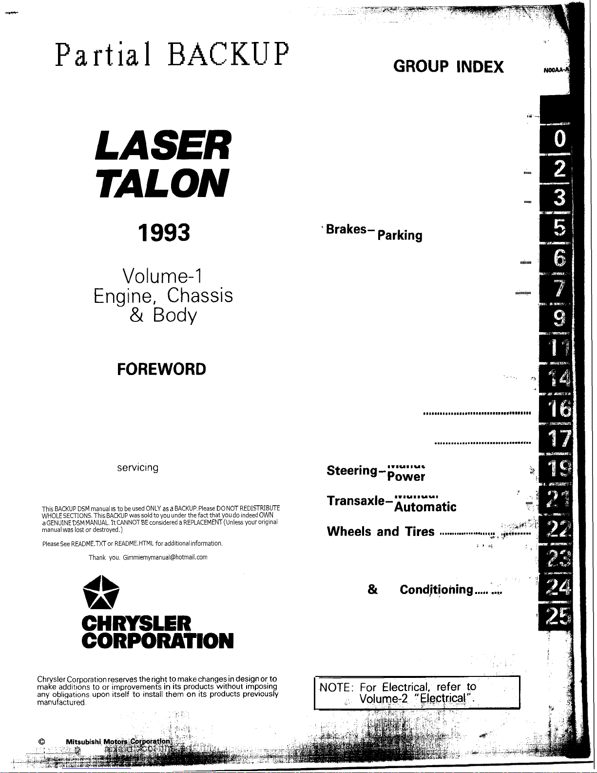
Partial
BACKUP
Service Manual
.i’
GROUP INDEX
NOSAl
LASER
TALON
1993
Volume-l
Engine, Chassis
& Body
FOREWORD
This Service Manual has been prepared with the
latest service information available at the time of
publication. It is subdivided into various group
categories and each section contains diagnosis,
disassembly, repair, and installation procedures
along with complete specifications and tightening
references. Use of this manual will aid in properly
performing any
servicrng
necessary to maintain or
restore the high levels of performance and reliability
designed into these outstanding vehicles.
This
BACKUP DSM
manual IS
to be used
ONLY
as a BACKUP. Please DO
NOT REDISTRIBUTE
WHOLE SECTIONS. This
BACKUP
was
sold to you
under the fact that
you do
indeed OWN
a GENUINE
DSM MANUAL. It
CANNOT
BE
considered a
REPLACEMENT
(Unless your orlglnal
manual was
lost or
destroyed.)
Please See
README.N
or
README.HTML for additional Information.
Thank you.
G~mm~emymanual@hotma~l.com
CHRYSLER
CORPORATION
Chrysler Corporation
reserves the right to make
changes in
design or
to
make additions to or improvements in
its
products
without
imposing
any
obligations
upon
itself to
install
them on
its
products previously
manufactured.
Introduction and
Master
Troubleshooting
.-I
. . . . . . . . . . . . . . . . . .
i
Lubrication and Maintenance . . . . . . . .El
Front Suspension
. . . . . . . . . . . . . . . . . . . . . . . . . . .
..A..
t
i
Rear Axle
. . . . . . . . . . . . . . . . . . . . . . . . . . . . . . . . . . . . . . . . . . . . .
..~...
Service
’ Brakes- Parking
. . . . . . . . . . . . . . . . . . . . . . . . . . . . . . . . . . . . . .
Clutch
. . . . . . . . . . . . . . . . . . . . . . . . . . . . . . . . . . . . . . . . . . . . . . . . .
..~.....
Cooling
. . . . . . . . . . . . . . . . . . . . . . . . . . . . . . . . . . . . . . . . . . . .
..~.....~~..
Engine
. . . . . . . . . . . . . . . . . . . . . . . . ..*..............................
Intake and Exhaust
. . . . . . . . . . . . . . . . . . . . . . . . . . . . .
Fuel System
‘,,, .*
. . . . . . . . . . . . . . . . . . ..*........................
4
Propeller Shaft
..,.....,....,.................m.......
Rear Suspension
.*........s........................
Manual
Steering-po,er
.h
. . . . . . . . . . . . . . . . . . . . . . . . . . . . . . . . . . .
..$\
Manual
i
Transaxle-Automatic
:
. . . . . , . . . . . . . . . . . . . .
r+:,
Wheels
and Tires
_. .;,:.;*&i
. .
. . . . . . . . . . . . . . . . . . . . .
.&......
j 8 .A$
: >
Body
. . . . . . . . . . . . . . . . . . . . . . . . . . . . . . . . . . . . . . . . . . . . . . . . . . ..*...**...
Heater & Air
CondjtJoning ..,.. ,.,.
. . ...’
Emission
Control
Systems
1
. . . . . . . . . . . . . .
0
1992
Mitsubishi)
L-.”
:
Printed in U.S.A.
BRAKES
SERVICE AND PARKING
CONTENTS
ANTI-LOCK BRAKING SYSTEM
TROUBLESHOOTING
.........................
9
BRAKE BOOSTER
..............................
71
BRAKE LINE
....................................
73
BRAKE PEDAL
..................................
63
ELECTRONIC CONTROL UNIT
<VEHICLES WITH
ABS>
...................
102
FRONT DISC BRAKE
..........................
76
G-SENSOR
<AWD-ABS>
...................
101
HYDRAULIC UNIT
<VEHICLES WITH
ABS>
...................
92
MASTER CYLINDER
........................... 67
PARKING BRAKES
.............................
103
REAR DISC BRAKE
............................
65
SERVICE ADJUSTMENT PROCEDURES
..a
47
ABS Power Relay Check ....................
62
Bleeding
.......................................
50
Brake Booster Operating
Inspection
.......
49
Brake Fluid Level Sensor Check ...........
48
Brake Pedal Inspection and Adjustment
...
47
Check Valve Operation Check ..............
49
Flat Battery Remedy .........................
62
Front Disc Brake Pad Check and
Replacement
..................................
51
Front Disc Brake Rotor Inspection
.........
53
Inspection of Hydraulic Unit
.................
59
Measurement of Wheel Speed Sensor
Output Voltage
................................
57
Parking Brake Lever Stroke Check
.........
48
Parking Brake Switch Check
................
49
Proportioning Valve Function Test
..........
50
Rear Brake Disc Run-out Check
............
57
Rear Brake Disc Run-out Correction
.......
57
Rear Brake Disc Thickness Check
..........
56
Rear Disc Brake Pad Check and
Replacement
..................................
55
Run-out Check
................................
54
Run-out Correction
...........................
54
Thickness Check
..............................
55
SPECIAL TOOLS
...............................
6
SPECIFICATIONS
...............................
2
General Specifications
........................
2
Lubricants
.....................................
5
Service Specifications
........................
4
Torque Specifications
..................
.:.
...
4
TROUBLESHOOTING
..........................
7
WHEEL
SPEED SENSOR
<VEHICLES WITH
ABS>
....................
95
CAUTION
When servicing brake assemblies or components, do not create dust by sanding, grinding or by cleaning
brake
parts
with a dry brush or with compressed air. A WATER DAMPENED CLOTH SHOULD BE USED.
Many
brake components contain asbestos fibers which can become air-borne if dust
is.created
during
service operations. Breathing dust which contains asbestos fibers can cause serious bodily harm.
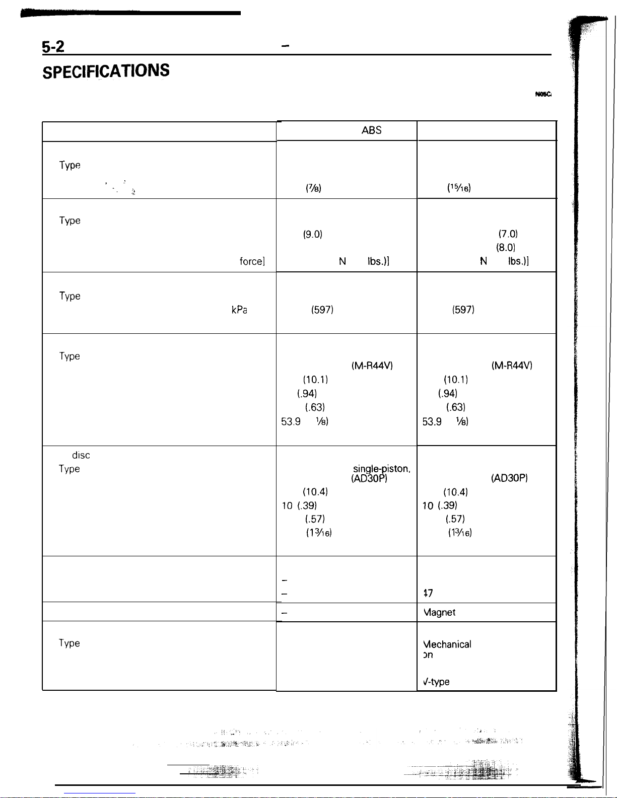
5-2
BRAKES
-
Specifications
SPECIFl,CATIONS
GENERAL SPECIFICATIONS
<Non-Turbo>
Items
Master cylinder
J-w
I.D. ’ ,, ’
,;!
mm (in.)
Brake booster
Tvw
Effective dia. of power cylinder mm (in.)
Boosting ratio [Brake pedal depressing
force]
5.0 [at 220 N (48
Ibs.)l
Proportioning valve
Type
Split point
Decompression ratio
kPa
(psi)
Front brakes
Type
Disc O.D.
Disc thickness
Pad thickness
Wheel cylinder I.D.
Clearance adjustment
mm (in.)
mm (in.)
mm (in.)
mm (in.)
Rear
drsc
brakes
Type
Disc O.D.
Disc thickness
Pad thickness
Wheel cylinder I.D.
Clearance adjustment
mm (in.)
mm (in.)
mm (in.)
mm (in.)
Rotor teeth
Front wheel side
Rear wheel side
Speed sensor
-
Parking brakes’
Tvw
Brake lever type
Cable arrangement
Vehicles without
ABS
Vehicles with ABS
Tandem type
(with level sensor)
22.2
(78)
Tandem type
(with level sensor)
23.8
P5/1d
Vacuum type
230
(9.0)
Vacuum type
Front side: 180
(7.0)
Rear side: 205
(8.0)
5.5 [at 220 N (48
Ibs.)l
Dual type
4,200
(597)
0.3
Dual type
4,200
(597)
3.3
Floating caliper, single-piston,
ventilated disc
(M-R44V)
256
(10.1)
24
i.94)
16.0
(.63)
53.9
(2
l/8)
Automatic
Floating caliper, single-piston,
ventilated disc
(M-R44V)
256
(10.1)
24
i.94)
16.0
(.63)
53.9
(2
%)
Automatic
Floating caliper,
single-piston,
ventilated disc
(AD30P)
265
(10.43
10
(39)
14.5
(.57)
30.1 (1
Yl6)
Automatic
Floating caliper, single-piston,
ventilated. disc
(AD30P)
265
(10.4)
10 l.39)
14.5
(.57)
30.1
(1
3/6)
Automatic
-
-
47
47
vlagnet
coil type
Mechanical brake acting
Vlechanical
brake acting
on rear wheels
3n
rear wheels
Lever type
-ever type
V-type
V-type
! y+
fr
. .
‘i
BR&gES -
Specifications
513
-
<Turbo>
Items
FWD
AWD
Master cylinder
Type
Tandem type
Tandem type
(with level sensor) (with level sensor)
I.D.
mm (in.) 25.4 (1)
25.4 (1)
Brake booster
Type
Vacuum type Vacuum type
Effective dia. of power cylinder
mm (in.) Front side: 188 (7.4)
Front side: 188 (7.4)
Rear side: 215 (8.5) Rear side: 215 (8.5)
Boosting ratio [Brake pedal depressing force]
6.0 [at 220 N (48
Ibs.)]
6.0 [at 220 N (48 Ibs.)]
‘.
Proportioning valve
Type
Dual type Dual type
Split point
kPa
(psi) 2,500 (363)
3,500 (508)
Decompression ratio
0.25
0.25
Front brakes
,,’ I
Type
Floating caliper, single-piston,
Floating caliper, double-piston
ventilated disc
(M-R46V)
ventilated disc
(M-R56W)
Disc O.D.
mm (in.)
256(10.1)
276 (10.9)
Disc thickness
mm (in.) 24
(94)
24
(.94)
Pad thickness
mm (in.) 16.0
(63)
16.0
(63)
Wheel cylinder I.D.
mm (in.) 60.3
(2?,)
41.3
(l”/*) x
2
Clearance adjustment
Automatic
Automatic
?ear
disc brakes
Type
Floating caliper, single-piston, Floating caliper, single-piston,
ventilated disc
(AD30P)
ventilated disc
(AD35P)
Disc
O.D.
mm (in.) 265 (10.4)
265 (10.4)
Disc thickness
mm (in.) 10 (39)
10
f.39)
Pad thickness
mm (in.) 14.5
(.57)
14.5
(.57)
Wheel cylinder I.D.
mm (in.)
30.1
(1
3/16)
34.9 (1
3h)
Clearance adjustment
Automatic Automatic
3otor
teeth*
Front wheel side
47
47
Rear wheel side
47
47
speed
sensor*
Magnet coil type Magnet coil type
‘arking
brakes
We
Mechanical brake acting Mechanical brake acting
on rear wheels
on rear wheels
Brake lever type
Lever type
Lever type
Cable arrangement
V-type
V-type
k ,.-YT--
Nult
The *symbol
indicates vehicles with ABS.
-
5-4
BRAKES
-
Specifications
SERVICE SPECIFICATIONS
Items
Standard value
Brake pedal height
mm (in.)
Brake pedal free play
mm (in.)
Brake pedal to floorboard clearance
mm (in.)
Parking brake lever stroke.
Output pressure proportioning valve
MPa
(psi)
Split point
<FWD>
<AWD>
Output pressure [input pressure]
<FWD>
<AWD>
DISC brake dragging force at hub bolt
N (Ibs.) [Nm (ft.lbs.)l
Booster push rod to master cylinder piston clearance
mm (in.)
9 inch brake booster
7 + 8 inch brake booster
Speed sensor’s internal resistance
k&
Clearance between the speed pole piece and
the toothed rotor mm (in.)
Lrmtt
Left/right proportioning valve out pressure difference
MPa
(psi)
DISC brake pad
thrckness
mm (in.)
Front
drsc
thickness
mm (in.)
Rear
dtsc thrckness
mm (in.)
DISC runout
mm (in.)
Front
Rear
Hub end play
mm
(In.)
NOTE
l
:
Vehicles
with ABS
TORQUE SPECIFICATIONS
Specifications
176-181 (6.9-7.1)
3-8
(.l-.3)
80 (3.1) or more
5-7 notches
3.95-4.45 (561-633)
3.45-3.95 (491-561).
5.15-5.65 (732-804) i8.2
(1,163)1
4.65-5.15 (661-732j.17.7 (1,095))
70
(15)
or less I4
(3)
or
less]
0.8-1.0
(.031-,039)
0.5-0.7
(.020-.028)
0.8-1.2"
0.3-0.9
(.012-,035)"
6
0.4 (57)
2.0
(.08)
22.4
(.882)
8.4
(.331)
0.07
(.0028)
0.08 l.0031)
0.2
(.008)
Items
Pedal support bracket installation bolts
Pedal support bracket installation nut
Pedal rod to pedal support bracket
Pedal rod to clutch pedal bracket
Clutch pedal bracket installation bolt
Turn-over spring mounting bolt
Stop lamp switch mounting nut
Clutch master cylinder installation nuts
Clutch pedal installation nut
Lever assembly (A) installation nut
Lever assembly (B) installation nut
I
:: ::I .:‘i j ,:
~~ -__
j
.
-, .‘- ‘+‘+gg&p.~j:
;.;1--?.+.k
Nm
8-12
IO-15
17-26
17-26
8-12
17-26
10-15
10-15
20-25
20-25
20-25
T
ft.lbs.
6-9
7-11
12-19
12-19.
6-9
12-19
7-11
7-11
14-18
14-18
-
BRAKES - Specifications
Items
Master cylinder to brake booster
Piston stopper bolt
Nipple
installation screw
Brake booster installation nuts
Fitting
Flared
brake line nuts
Brake hose bracket installation bolts
Front
disc brake assembly installation bolts
Lock pin (front)
Guide pin (front)
Bleeder screw
Wheel bearing nut
Dust shield to axle beam
Rear disc brake assembly installation bolts
Drive shaft to companion flange
Companion flange to rear axle shaft
Brake hose to caliper body (rear)
Lock pin (rear)
Guide pin (rear)
Spindle lever to parking brake lever
Rear speed sensor installation bolt
Speed sensor bracket installation bolt
Rotor to front hub
Rotor to rear hub
Nm
8-12
1.5-3.0
1.5-3.0
11-17
15-18
13-17
17-26
80-100
64-86
64-86
7-9
200-260
9-14
50-60
55-65
160-200
25-35
22-32
22-32
40-55
9-14
9-14
7-l 1
9-14
ft.lbs.
6-9
l-2
l-2
8-12
11-13
9-12
12-19
58-72
46-62
46-62
5-7
144-188
”
7-10
36-43
39-47
116-159
18-25
16-23
16-23
29-40
7-10
7-10
5-a
7-10
LUBRICANTS
No!xD-
Items
Brake fluid
Specified lubricant
MOPAR Brake Fluid/
Conforming to
DOT3
or
DOT4
Brake pedal bushing inner surface
Clevls
pin and washer
Parking brake lever sliding parts
Bushing inner surface
MOPAR Multi-mileage Lubricant
Part No. 2525035 or equivalent
5-50
BRAKES
-
Service Adjustment
Proi?edur&
Brake
booster
side
Spring
’
/
Valve
Pressure
gauge
Pressure
PropGtioning
valve
14LO181
input pressure
14uoo55
2.
Check the operation of the check valve by using a
vacuul
pump.
Vacuum pump connection Accept/reject criteria
Connection at the brake A negative pressure (vacuum)
is
booster side
@
created and held.
Connection at the -intake
manifold side
@
A negative pressure (vacuum) is not
created.
Caution
If the check valve is defective, replace it as an
assemb!
unit together with the vacuum hose.
PROPORTIONING VALVE FUNCTION TEST
NO!iR(r
1.
Connect two pressure gauges, one each to the input sid
and output side of the proportioning valve, as shown,
2. Air bleed the brake line and the pressure gauge.
3. While gradually depressing the brake pedal, make th
following measurements and check to be sure that th
measured values are within the allowable range.
(1) Output pressure begins to drop relative to inpl
pressure (split point).
Standard value:
<PWD>
3.95-4.45
MPa
(561-633 psi
<AWD>
3.45-3.95
MPa
(491-561
ps
(2) Output fluid pressure when input fluid pressure are a
follows.
Standard value:
<PWD>
5.15-5.65
MPa (732-804 ps
[at 8.2
MPa
(1,163 psi))
<AWD>
4.65-5.15
MPa
(661-732
ps
[at 7.7
MPa
(1,095 psi)]
(3) Output pressure difference between left and
rig1
brake lines
Limit: 0.4
MPa
(57 psi)
4. If the measured pressures are not within the permissibl
ranges, replace the proportioning valve.
BLEEDING
No5FY
When the master cylinder is empty of brake fluid, bleed i
from the master cylinder by proceeding with procedures
(
thru (6). (Because this master cylinder is not equipped with
check valve.)
When brake fluid remains in the master cylinder, proceed wi
step (6).
(1)
Disconnect the brake tube from the master cylinder.
(2) Two
persqs
should conduct the air bleeding, one
perso
slowly depressing the brake pedal and holding the
ped:
depressed.
i .I.
.[ j,
‘I
- .~ j, Z’:. ~. jl
2;:‘,.
Y .‘.:
./ ‘:” ‘: ,,
.
8,
, .
.;$y; ii; :: 1
. .
i;, d
BRAKES
-
Service Adjustment Procedures
5-51
2
3
14A0454
When new
When worn
14G0017
1
14
LO169
check the sliding co
WsTm~
3
..“.W% ,Y :
sleeve and guide pin
-~
I
.
_. ;;
:i
‘.
(3) In this condition, the other person should use a finger to
close the outlet part of the, master cylinder, and then the
first person should release the brake pedal.
(4) Steps (2) and (3) should be repeated three or four times,
and then the master cylinder should be filled with brake
fluid to the specified level.
NOTE
The air is completely bled from the master cylinder by steps
(1) to
(4).
(5) Connect the brake tube to the master cylinder.
(6) Start the engine; then, in the sequence shown in the
illustration, bleed the air from each wheel cylinder.
Specified brake fluid: MOPAR Brake Fluid/
Conforming to
DOT3
or DOT4
Caution
1.
Use the specified brake fluid. Avoid using a mixture
of the specified brake fluid and other fluid.
2. If brake fluid is exposed to the air, it will absorb
moisture; as water is absorbed from the atmosphere, the boiling point of the brake fluid will
decrease and the braking performance will be
seriously impaired. For this reason, use a hermeti-
cally sealed 1 lit. (1.06 qt.) or 0.5 lit. (0.52 qt.) brake
fluid container.
3. Firmly close the cap of the brake fluid container
after use.
4. For vehicles with the anti-lock braking system, be
sure to install a filter to the master cylinder
reservoir tank when supplying brake fluid.
ORDINARY AIR-BLEEDING PROCEDURES
(1) Depress the brake pedal several times until resistance is
felt; then, with the pedal depressed, loosen the bleeder
screw
l/3
to
l/2
turn and then tighten it before the fluid
pressure is all gone.
(2) Release the brake pedal. Repeat this procedure until there
are no more air bubbles in the brake fluid.
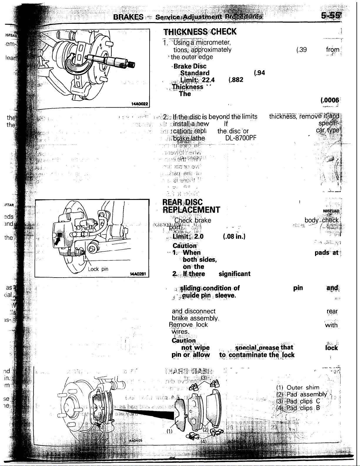
FRONT DISC BRAKE PAD CHECK AND
REPLACEMENT
N05FOAF
NOTE
The brake pads have wear indicators that contact the brake
disc when the brake pad thickness becomes 2 mm
(.08
in.),
and emit a squealing sound to warn the driver.
1. Check brake pad thickness through caliper body check
port.
Standard value: 10.0 mm
(.39
in.)
Limit: 2.0 mm
(.08
in.)
Caution
1. When the limit is exceeded, replace the pads at
both sides, and also the brake pads for the wheels
on the opposite side at the same time.
2. If there is a
significant difference
.in
the thick-
nesses
of the pads
5-52
14LO291
2. Remove guide pin. Lift caliper assembly and retain wit
wires.
Caution
Do not wipe off the special grease that is on the guid
pin or allow it to contaminate the guide pin.
3.
Remove the following parts from caliper support.
0
Pad &wear indicator assembly
0
Pad assembly
@
Clip
@I
Inner shim
@
Outer shim
1 -piston type
14N0284
P-piston type
\
14AO400
4. With the pad removed, use a spring balance to
measure
the rotation sliding resistance of the hub in the forward di
rection.
NOTE
Tighten the nuts in order to secure the disc to the hub.
5.
Securely attach the pad clip to the caliper support.
6.
Clean piston and insert into cylinder with tool.
7. Be careful that the piston boot does not become
caughl
when lowering the caliper assembly and install the guidt
pin.
gui
isur
dd
lght
clidc
Pad assembly
luter shim
nner
shim
43l
a
14FOO97
14A0399
Apply repair kit grease to both sides of the inner shims.
Specified grease: Brake grease SAE 5310,
NLGI No.1
Caution
1. Make sure that the friction surfaces of pads and
brake discs and free of grease and other contaminants.
2.
The grease should never squeeze out from around
the shim.
9.
Check the disc brake drag force as follows.
(1) Start the engine, and after depressing the brake pedal
hard two or three times, stop the
(2) Turn brake disc forward 10
tie&.
engine.
(3) Use a spring balance to
meastiie fh-e
rotation Sliding re-
sistance of the hub in the forward direction.
(4) Calculate the drag torque of the disc brake (difference
between measured values in 3 and 4).
Standard value: 70 N (15.4
Ibs.)
or less
10. If the disc brake drag force exceeds
tlie
standard value,
disassemble piston and clean the piston. Check for corrosion or worn piston seal, and check the sliding condition of
the lock pin and guide pin.
FRONT DISC BRAKE ROTOR INSPECTION
CAUTION
When servicing disc brakes, it is necessary to exercise caution to keep the disc brakes within the
allowable service values in order to maintain normal brake operation.
Before re-finishing or re-processing the brake disc surface, the following conditions should be checked.
Inspection items
Remarks
Scratches, rust, saturated lining materials
and wear
l If the vehicle is not driven for a certain period, the sections of the discs
that are not in contact with lining will become rusty, causing
noise and
shuddering.
l
If grooves resulting from excessive disc wear and scratches are not removed prior to installing a new pad assembly, there will momentarily
be
inappropriate
contact between the disc and the
lining
(pad).
Run-out
or drift
Ehange
in thickness (parallelism)
Excessive run-out or drift of the discs will increase the pedal depression
resistance due to piston knock-back.
If the thickness of the disc changes, this will cause pedal pulsation, shud-
dering and surging.
14A0391
RUN-OUT CHECK
1.
Remove the caliper support; then raise the caliper ass
bly
upward and secure by using wire.
2.
Inspect the disc surface for grooves, cracks, and rust. Cl
the disc throughly and remove all rust.
3. Place a dial gauge approximately 5 mm
(.2
in.) from
thi
outer circumference of the brake disc, and measure
tt$
run-out of the disc.
_i
Limit: 0.07 mm
(.0028
in.)
-2
NOTE
Tighten the nuts in order to secure the disc to the hub..
‘l;
i,!
..,;
RUN-OUT CORRECTION
NOSFTAB
1.
If the run-out of the brake disc is equivalent to or exceeds
the limit specification, change the phase of
the
disc and
hub, and then measure the run-out again.
(1) Before removing the brake disc, chalk both sides of the
wheel stud on the side at which run-out is greatest.
(2) Remove the brake disc, and then place a dial gauge
2s
shown in the illustration; then move the hub in the axial
direction and measure the play.
Limit: 0.2 mm
(.008
in.)
If the play is equivalent to or exceeds the limit, disassemble the hub knuckle and check each part.
2.
(3) If the play does not exceed the limit specification, and
then check the run-out of the brake disc once again.
Mount the brake disc on the position dislocated from
the chalk mark.
If the run-out cannot be corrected by changing the phase
of the brake disc, replace the disc or turn rotor with on the
car type brake lathe (MAD
DL-8700PF
or equivalent).’
.,
“, . . . -..
: : :.. t
,:...!b
THl,~,KNES~i;CHECK
,
.‘i
.- _d
--.-.--.
1:
‘Using $.$i,crometer, measure disc thickness at eight posi-
I
tions;:‘.@‘proximately
45” apart and 10 mm
(.39
in.) in
f,r$,m;,
i theouter’edge
of the disc.
‘I
+
Brbke.Disc Thickness
..!+@Card value: 24 mm
(94
in.)
i
,,~~~:-~4!-~~~t;:22.4
mm
(.882
in.)
: ,aThrckness
Variation (At least 8 position)
_
The ‘*difference between any thickness. measure-
ments should not be more than 0.015 mm
(.0006:
in.).
,,
7.9’-,... .J
.
: .A12fi: If~thei;di& is
beyond
t&
Jim@
for
thickneT.%, ‘ie’mdv
.,.
one. If thickness variation exceeds the
ace the:disc”or turn. rotor with on the.
(MAD,
DL-87OOPF
or equivalent).
-
;
_:.j ::
!
‘_,
I
i
..;, ‘I
t&;&C
BRAKE PAD CHECK AND
.,
.
.:L”” cn:
,.,
1.
~:“ch&ii -brake
pad thickness through, caliper body$%ck.~
:?;{&:?p., d ii,; ,i..i
; I&+# ~4:
‘ ” :’
/I..: “j.
. .
~~Tl$$$‘~&b
mm
(08 cn.)
-.‘-‘: (~~#&q
,,I,.
:: y;.
/.
C&&ion”
,- ‘-, -,
iii,,,
I.“‘?
,t
--. +-When
the limit is exceeded, replace the pad&at-:
,--both&sides,
and also the brake pads for the wheels
onth-e
opposite side at the same time.
&.Jf,tb@re is a
signjfjcant
difference in the thicknesses
of the pads on the left and right sides, check the
A
.J. :%!idi,~g!~ondStion.of
the piston, ‘lock
p,in
sleeve
;a,$$
f * ,midq py I sleye.
_, ,: .’ i.
. .
ii’.
2.
Loosen the parking brake cable (from the vehicle interior),
an$dis.co-nnect
the parking brake end installed to the
rear
I I
I I
orake,. assemory.
3.
f5$_move.,lock
pin. Lift caliper assembly and retain
‘&h,
yps..
,
(y&on,
DO
r$$v$e
off. the
stiecial!.grease.
that’ is on the
&ck
pi”
cii’@!fow
it
to..c,ontait;inate tl;<jock
pin.
j
4. Remove. the- following parts from caliper support.
,,
f :.
,3-
:: ” ,, ” -
_.__ _, .“_,.
/
‘7
,
.< :$, ~
. .
6
BRAKES
-
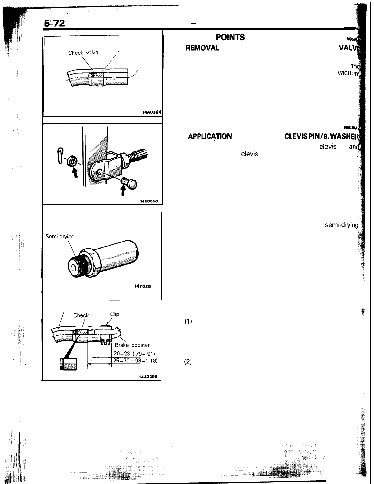
Brake Booster
Vacuum hose
14AO394
14u0050
Semidrvina sealant
141626
Vacuum hose
I
Chevk
valve
mm (in.)
14AO395
SERVICE
PO@JTS
OF REMOVAL
Nocm
6.
REM&AL
OF VACUUM HOSE WITH CHECK
VA+
NOTE
Since the check valve is fit to the vacuum hose, replace
th
check valve as an assembly unit together with the
vacuur
hose if the check valve is defective.
SERVICE POINTS OF INSTALLATION
10.
APPLDJTION
OF GREASE TO CLEVIS
PIN/g.
WASHEI
After applying the specified grease to the
clevis
pin
an
washer, insert the
cievis
pin and bend the cotter pin tightly
Grease: MOPAR Multi-mileage Lubricant
Part No. 2525035 or equivalent
7. APPLICATION OF SEALANT TO FITTING
When installing the vacuum hose fitting, apply
semi-cfryin!
sealant to its threaded portion.
6. INSTALLATION OF VACUUM HOSE WITH CHECK
VALVE
(1)
Attach the vacuum hose so that it may be inserted to a
dimension illustrated.
Caution
Prevent interference between the check valve and
brake booster.
(2)
The vacuum hose at the engine should be securely
connected until it contacts the hexagonal edge of the
fitting, and then should be secured by the hose clip.
N0sJa
4LVI
:e
the
cuu<
‘=JD4\
;HER
and
!htly.
Wg
CK
3a
nd
3ly
he
P.
BRAKES
-
Brake Line
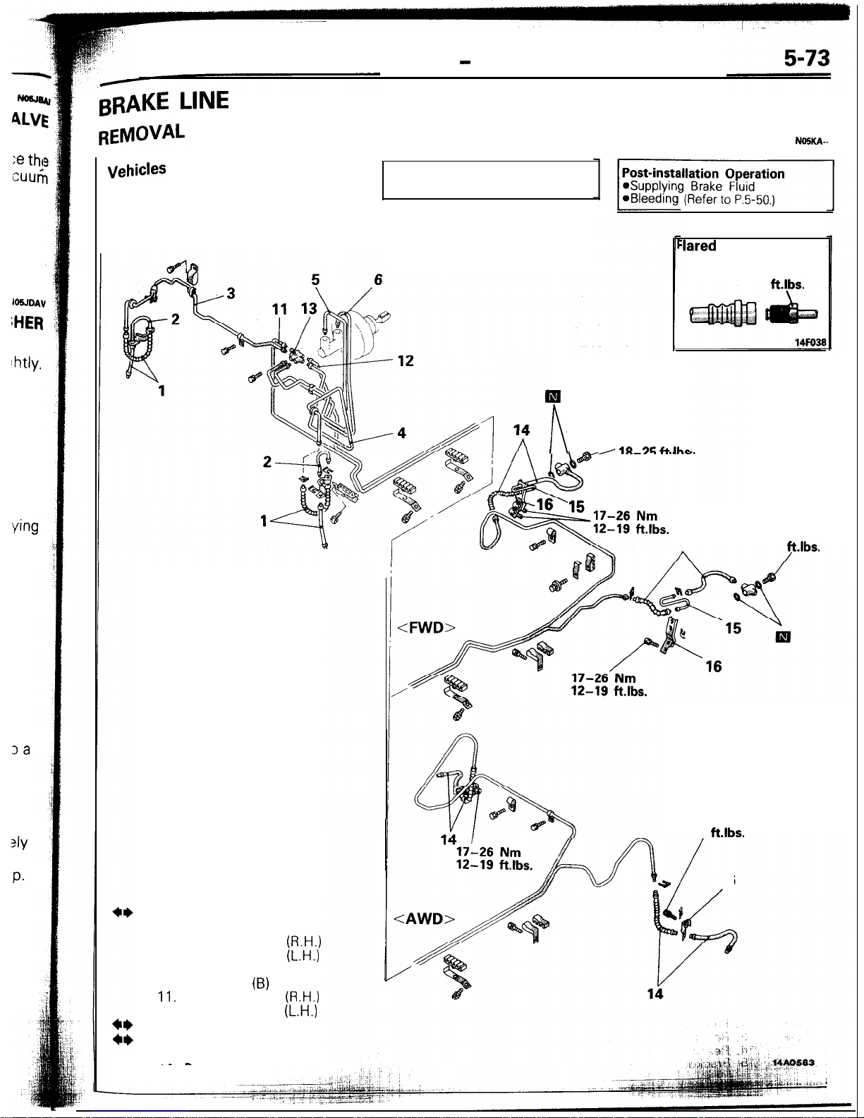
BRAKE LINE
REMOVAL
AND INSTALLATION
NOSKA--
1. Front brake hose
2. Strut brake tube
3. Front brake tube
(R.H.)
4. Front brake tube
(L.H.)
5. Brake tube (A)
6. Brake tube
(B)
11.
Main brake tube
(R.H.)
12. Main brake tube
(L.H.)
13. Proportioning valve
14. Rear brake hose
15. Rear axle brake tube
._-
Ill
n
25-35 Nm
I
111-7G f-t Ihr
:lared brake line nuts
13-17 Nm
9-12
ftlbs.
vehicles
without ABS
Pre-removal Operation
*Draining of Brake Fluid
14
25-35 Nm
18-25
ft.lbs.
17-26 Nm
12-19
ft.lbs.
+
16
16. Bracket
a-.
i
.-J
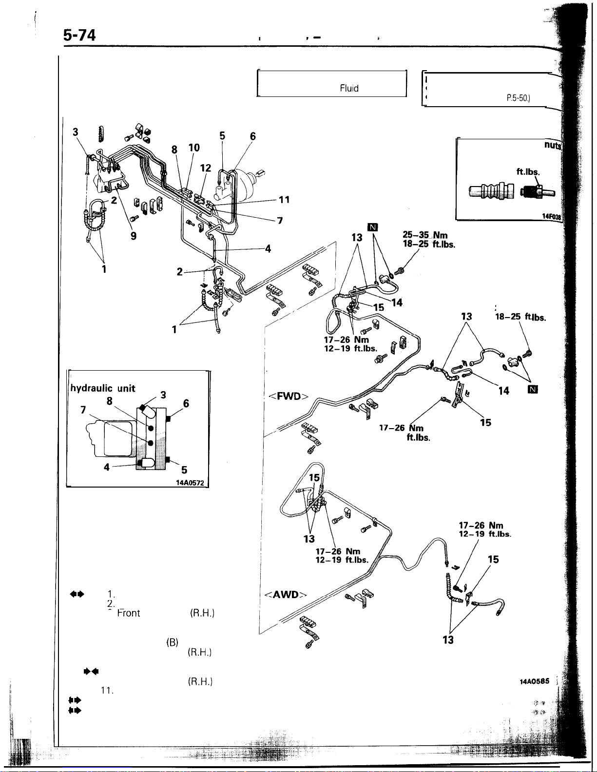
5-74
BRAKES
-
Brake tine
Vehicles with ABS
Pre-removal Operation
*Draining of Brake
Fluid
,“i
Post-installation Operation
A
@Supplying Brake Fluid
1
l
Bleeding (Refer to
P.5-50.)
-
Connecting part of
14AO572
I.
Front brake hose
2.
Strut brake tube
- -
25-35 Nm
Ibs.
12-19
ft.lbs.
Flared brake line
ns
13-17 Nm
9-12
ftlbs.
15. Bracket
3.
f-ront
brake tube
(R.H.)
4. Front brake tube (L.H.)
5. Brake tube (A)
6. Brake tube
(B)
7. Rear brake tube
(R.H.)
8. Rear brake tube (L.H.)
I)+
9. Hydraulic unit
10. Main brake tube
(R.H.)
11.
Main brake tube (L.H.)
::
12. Proportioning valve
13. Rear brake hose
14. Rear axle brake tube
14AO585
;
SERVICE POINTS OF REMOVAL
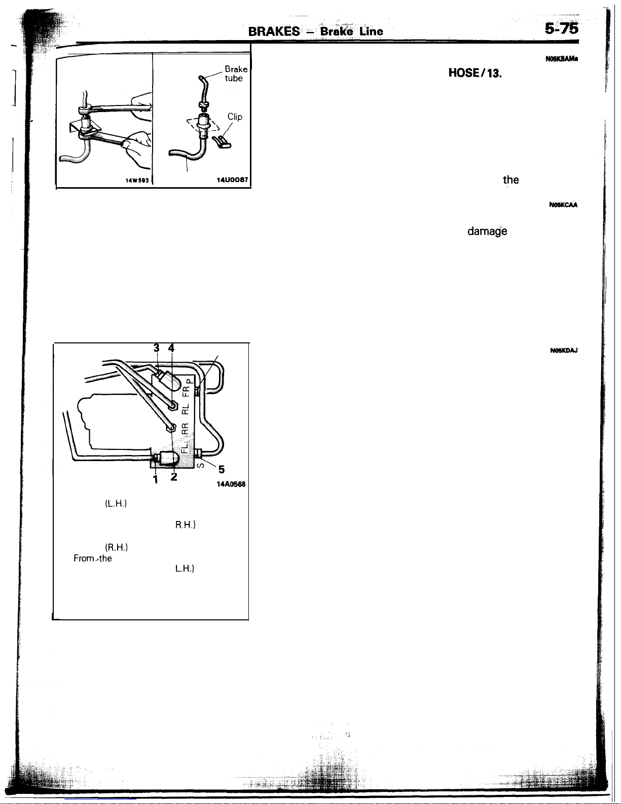
14w593
Brake hose
woo07
s 4
6
1. REMOVAL OF FRONT BRAKE
HOSE/13.
REAR BRAKE
HOSE
(1) Holding the lock nut on the brake hose side, loosen the
flared brake line nut.
(2) Pull off the brake hose clip and remove the brake hose
from the bracket.
12. REMOVAL OF PROPORTIONING
VALVE
Do not disassemble the proportioning valve because its
performance depends on the set load of the spring.
INSPECTION
No6KcM
l Check the brake tubes for cracks, crimps and corrosion.
l Check the brake hoses for cracks,
damade
and leakage.
l
Check the flared brake line nuts for damage and leakage.
SERVICE POINTS OF INSTALLATION
NOSKOAJ
9. CONNECTION OF TUBE TO HYDRAULIC UNIT
Connect the tubes to the hydraulic ‘unit as shown in the
illustration.
i 2
14AO568
1.
From the hydraulic unit to the front
brake
(L.H.)
2. From the hydraulic unit to the proportioning valve (Rear,
R.H.)
3. From the hydraulic unit to the front
brake
(R.H.)
4. From,the hydraulic unit to the proportioning valve (Rear,
L.H.)
5. From the master cylinder
(for left front and right rear)
6. From the master cylinder
(for right front and left rear)
!
-;-
596
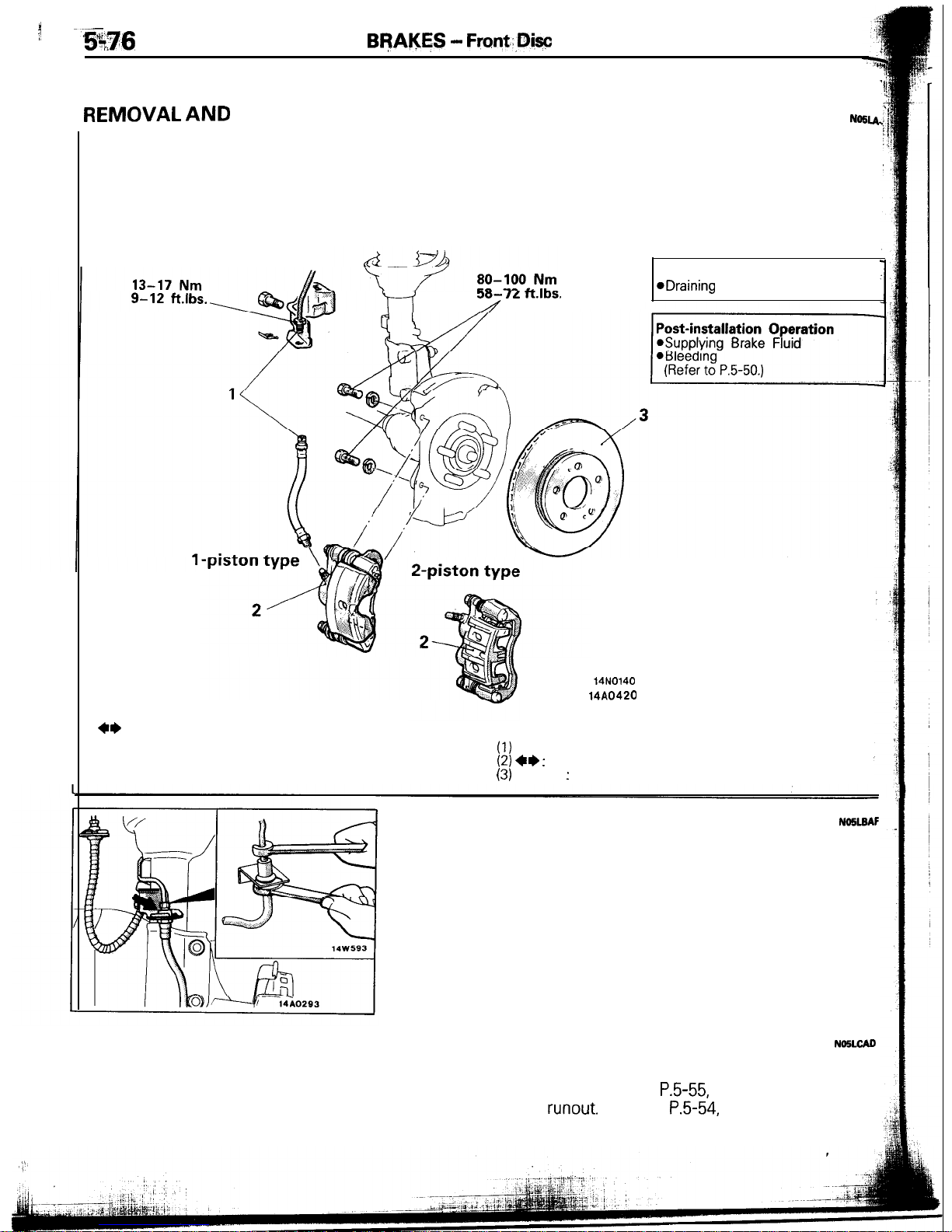
FRONT DISC BRAKE
Bf?Al$ES - Front.:,Diw
Brake
REMOVAL
AND INSTALLATION
N=U.
3U- IL l-LIDS.
Y-i
A
14N0140
14A0420
Pre-removal Operation
eDraining
of Brake Fluid
Removal steps
+e
l
1. Connection for the brake hose and the
brake tube
NOTE
l
+
2. Front brake assembly
(1)
Reverse the removal procedures to reinstall.
3. Brake disc
(2) ++ :
Refer to “Service Points of Removal”.
(3)
l +
:
Refer to “Service Points of Installation”.
SERVICE POINTS OF REMOVAL
No5LsAF
1. DISCONNECTION OF BRAKE HOSE
Holding the nut on the brake hose side. Loosen the flared
brake line nut.
INSPECTION
NNiLCID
INSPECTION OF BRAKE DISC
l
Check disc for wear. (Refer to
P.5-55,
Thickness Check.)
l
Check disc for
runout.
(Refer to
P.5-54,
Run-out Check.)
l Check disc for damage.
 Loading...