

Page 1
Operating Manual
SW6D5C-GPPW-E
Page 2
• SAFETY PRECAUTIONS •
(Always read these instructions before using this equipment.)
Before using this product, please read this manual and the relevant manuals introduced in this manual
carefully and pay full attention to safety to handle the product correctly.
The instructions given in this manual are concerned with this product. For the safety instructions of the
programmable controller system, please read the CPU module user's manual.
In this manual, the safety instructions are ranked as "DANGER" and "CAUTION".
DANGER
!
CAUTION
!
Note that the !CAUTION level may lead to a serious consequence according to the circumstances.
Always follow the instructions of both levels because they are important to personal safety.
Please save this manual to make it accessible when required and always forward it to the end user.
Indicates that incorrect handling may cause hazardous conditions,
resulting in death or severe injury.
Indicates that incorrect handling may cause hazardous conditions,
resulting in medium or slight personal injury or physical damage.
[Design Instructions]
!
DANGER
• For data change, program change, and status control made to the PLC which is running from a
Personal computer, configure the interlock circuit externally so that the system safety is
ensured. The action to be taken for the system at the occurrence of communication errors
caused by such as loose cable connection must be determined for online operation of PLC from
Personal computers.
!
CAUTION
• Before connecting a Personal computer to a CPU module in the RUN status and carrying out
online operation (particularly program changes, forced output, and changing the operating
status), read the manual carefully and confirm safety. Failure to do this could result in damage to
the machine and accidents due to misoperation.
A - 1 A - 1
Page 3

Revisions
The manual number is given on the bottom left of the back cover.
Print Date
Manual Number Revision
Sep, 1999 IB(NA)0800031-A First edition
Feb, 2000 IB(NA)0800031-B Second edition
Jun, 2000 IB(NA)0800031-C Third edition
Sep, 2000 IB(NA)0800031-D
• The Windows-based software products were integrated into the
Mitsubishi MELSOFT Integrated Software series from the Mitsubishi
MELSEC general-purpose PLC series.
• The software package names (GPP Function, Logic test function (LLT),
etc.) were standardized as the product names (GX Developer, GX
Simulator, etc.).
• Addition of the description of label programming
• Addition of the description of MELSECNET/H remote I/O
• Addition of the description of Ethernet diagnostics
• Addition of the description of instruction help
• Addition of the description of list monitoring
This manual confers no industrial property rights or any rights of any other kind, nor does it confer any patent
licenses. Mitsubishi Electric Corporation cannot be held responsible for any problems involving industrial property
rights which may occur as a result of using the contents noted in this manual.
2000 MITSUBISHI ELECTRIC CORPORATION
A - 2 A - 2
Page 4

INTRODUCTION
Thank you for choosing the Mitsubishi MELSOFT series Integrated FA software.
Read this manual and make sure you understand the functions and performance of MELSEC series sequencer
thoroughly in advance to ensure correct use.
Please make this manual available to the end user.
SAFETY PRECAUTIONS..............................................................................................................................A - 1
REVISIONS....................................................................................................................................................A - 2
CONTENTS....................................................................................................................................................A - 3
About Manuals .............................................................................................................................................A - 13
How the manual describes the explanation is shown below ......................................................................A - 14
Abbreviations and Terms in This Manual....................................................................................................A - 16
CONTENTS
Chapter 1 GENERAL DESCRIPTION 1- 1 to 1- 12
1.1 Functions Lists ........................................................................................................................................ 1- 3
1.2 FX Series Programming ........................................................................................................................ 1- 10
1.3 Basic Key Specifications........................................................................................................................ 1- 12
Chapter 2 SYSTEM CONFIGURATION 2- 1 to 2- 10
2.1 Connection from the Serial Port ............................................................................................................. 2- 1
2.2 Connection from the Interface Boards ................................................................................................... 2- 4
2.3 System Equipment Lists ......................................................................................................................... 2- 5
2.4 Precautions for Handling Project on the Earier Versions ...................................................................... 2- 8
2.4.1 When handling a project on GX Developer (SW4D5-GPPW-E) or earlier .................................... 2- 8
2.4.2 When handling a project on GX Developer (SW5D5-GPPW-E) or earlier .................................... 2- 9
Chapter 3 COMMON OPERATIONS 3- 1 to 3- 23
3.1 List of Shortcut Keys and Access Keys ................................................................................................. 3- 1
3.2 Project Designation................................................................................................................................. 3- 5
3.2.1 Saving a project................................................................................................................................ 3- 6
3.2.2 Opening a project............................................................................................................................. 3- 9
3.3 Cut, Copy, and Paste............................................................................................................................. 3- 10
3.3.1 Cut and paste.................................................................................................................................. 3- 10
3.3.2 Copy and paste ............................................................................................................................... 3- 12
3.3.3 Notes on cutting, copying and pasting network parameters ......................................................... 3- 14
3.4 Toolbar ................................................................................................................................................... 3- 16
3.5 Status Bar............................................................................................................................................... 3- 17
3.6 Zooming in on or out of the Edit Screen................................................................................................ 3- 18
3.7 Project Data List..................................................................................................................................... 3- 19
3.8 Comment Display................................................................................................................................... 3- 21
3.9 Statement Display.................................................................................................................................. 3- 21
3.10 Note Display......................................................................................................................................... 3- 21
3.11 Alias Display......................................................................................................................................... 3- 22
3.12 Comment Format................................................................................................................................. 3- 22
A - 3 A - 3
Page 5

3.13 Alias format display.............................................................................................................................. 3- 23
3.13.1 Replace device name and display................................................................................................ 3- 23
3.13.2 Arrange with device and display................................................................................................... 3- 23
Chapter 4 INITIALIZATION 4- 1 to 4- 28
4.1 Creating a Project ................................................................................................................................... 4- 1
4.2 Opening the Existing Project File ........................................................................................................... 4- 3
4.3 Closing a Project File.............................................................................................................................. 4- 4
4.4 Saving a Project...................................................................................................................................... 4- 4
4.5 Saving a Project with a New Name........................................................................................................ 4- 5
4.6 Deleting a Project.................................................................................................................................... 4- 5
4.7 Vrifying Data in Projects ......................................................................................................................... 4- 6
4.8 Copying a Project.................................................................................................................................... 4- 8
4.9 Adding Data to a Project........................................................................................................................ 4- 10
4.10 Copying Data within a Project ............................................................................................................. 4- 11
4.11 Deleting Data in a Project.................................................................................................................... 4- 13
4.12 Renaming Data in a Project................................................................................................................. 4- 14
4.13 Changing the Ladder and SFC with each other ................................................................................. 4- 15
4.14 Changing the PLC Type of a Project................................................................................................... 4- 16
4.15 Reading Other Format Files ................................................................................................................ 4- 17
4.15.1 Reading GPPQ, GPPA, FXGP(DOS) or FXGP(WIN) files ......................................................... 4- 17
4.15.2 Reading a MELSEC MEDOC format file (Printout) ..................................................................... 4- 21
4.15.3 Reading a MELSEC MEDOC format file......................................................................................4- 22
4.16 Exporting GPPQ, GPPA, FXGP(DOS) or FXGP(WIN) Files ............................................................. 4- 24
4.17 Starting Multiple Projects..................................................................................................................... 4- 28
4.18 Existing GX Developer......................................................................................................................... 4- 28
Chapter 5 STANDARDIZING THE PROGRAMS 5- 1 to 5- 28
5.1 Label programming................................................................................................................................. 5- 1
5.1.1 Label programming sequence......................................................................................................... 5- 6
5.1.2 Label programming input method.................................................................................................... 5- 7
5.1.3 Making global variable/local variable setting................................................................................... 5- 8
5.1.4 Making automatic device setting .................................................................................................... 5- 12
5.1.5 Deleting External............................................................................................................................. 5- 13
5.1.6 All deletion....................................................................................................................................... 5- 13
5.1.7 Importing device comments............................................................................................................ 5- 14
5.1.8 Exporting to device comments ....................................................................................................... 5- 15
5.1.9 Converting label programs into actual programming (Compile).................................................... 5- 17
5.2 About Macros ......................................................................................................................................... 5- 19
5.2.1 Registering a macro........................................................................................................................ 5- 21
5.2.2 Utilizing a macro.............................................................................................................................. 5- 23
5.2.3 Deleting a macro ............................................................................................................................. 5- 25
5.2.4 Displaying macro............................................................................................................................. 5- 26
Chapter 6 CREATING CIRCUIT 6- 1 to 6- 50
6.1 Restrictions on Circuit Creation.............................................................................................................. 6- 7
A - 4 A - 4
Page 6

6.1.1 Restrictions in circuit display window .............................................................................................. 6- 7
6.1.2 Restrictions in circuit edit window.................................................................................................... 6- 8
6.2 Creating and Editing Circuits ................................................................................................................. 6- 12
6.2.1 Inputting contacts and application instructions .............................................................................. 6- 12
6.2.2 Inputting lines (vertical and horizontal)........................................................................................... 6- 14
6.2.3 Deleting contacts and application instructions ............................................................................... 6- 16
6.2.4 Deleting connecting lines................................................................................................................ 6- 17
6.2.5 Inserting and deleting in circuit blocks............................................................................................ 6- 18
6.2.6 Inserting NOPs ................................................................................................................................ 6- 20
6.2.7 Deleting NOPs................................................................................................................................. 6- 20
6.2.8 Cutting, copying and pasting circuits.............................................................................................. 6- 21
6.2.9 Undo the last operation................................................................................................................... 6- 23
6.2.10 Returning to the status after ladder conversion ........................................................................... 6- 24
6.3 Changing T/C Setting Values ................................................................................................................ 6- 25
6.4 Find and Replace................................................................................................................................... 6- 27
6.4.1 Finding a device .............................................................................................................................. 6- 29
6.4.2 Finding an instruction...................................................................................................................... 6- 31
6.4.3 Finding a step No. ........................................................................................................................... 6- 32
6.4.4 Finding a character string ............................................................................................................... 6- 34
6.4.5 Finding a contact/coil ...................................................................................................................... 6- 35
6.4.6 Finding data..................................................................................................................................... 6- 36
6.4.7 Replacing a device.......................................................................................................................... 6- 37
6.4.8 Replacing an instruction.................................................................................................................. 6- 39
6.4.9 Changing A and B contacts ............................................................................................................ 6- 41
6.4.10 Replacing a character string ......................................................................................................... 6- 42
6.4.11 Replacing the module's first I/O number ...................................................................................... 6- 44
6.4.12 Changing the statement or note type ........................................................................................... 6- 45
6.4.13 Replacing data .............................................................................................................................. 6- 46
6.4.14 Searching for a contact coil .......................................................................................................... 6- 47
6.4.15 Searching for a device-use instruction ......................................................................................... 6- 49
Chapter 7 CREATING INSTRUCTION LIST 7- 1 to 7- 11
7.1 Common Notes on Instruction List Creation .......................................................................................... 7- 1
7.2 Creating a Program Instruction list......................................................................................................... 7- 3
7.2.1 Inputting a contact or application instruction ................................................................................... 7- 3
7.2 2 Changing the existing program in overwrite mode ......................................................................... 7- 4
7.2.3 Inserting or adding the existing program......................................................................................... 7- 5
7.2.4 Deleting the existing program list .................................................................................................... 7- 6
7.2.5 Inserting NOPs ................................................................................................................................ 7- 7
7.2.6 Deleting NOPs ................................................................................................................................. 7- 7
7.3 Find and Replace.................................................................................................................................... 7- 8
7.3.1 Finding a device ............................................................................................................................... 7- 8
7.3.2 Finding an instruction....................................................................................................................... 7- 8
7.3.3 Finding a step No. ............................................................................................................................ 7- 8
7.3.4 Finding a character string ................................................................................................................ 7- 8
7.3.5 Finding a contact/coil ....................................................................................................................... 7- 8
7.3.6 Replacing a device........................................................................................................................... 7- 8
A - 5 A - 5
Page 7

7.3.7 Replacing an instruction................................................................................................................... 7- 8
7.3.8 Changing an A or B contact............................................................................................................. 7- 9
7.3.9 Replacing a character string ............................................................................................................ 7- 9
7.3.10 Change module start address ....................................................................................................... 7- 9
7.3.11 Changing the statement or note type ............................................................................................ 7- 9
7.3.12 Searching for a contact coil ........................................................................................................... 7- 9
7.3.13 Searching for an instruction using a device .................................................................................. 7- 9
7.4 Display.................................................................................................................................................... 7- 10
7.4.1 Displaying a Alias............................................................................................................................ 7- 10
7.5 Switching Read and Write Modes ......................................................................................................... 7- 11
7.5.1 Switching to read mode .................................................................................................................. 7- 11
7.5.2 Switching to write mode.................................................................................................................. 7- 11
7.5.3 Switching to circuit mode ................................................................................................................ 7- 11
7.6 Changing T/C Setting Values ................................................................................................................ 7- 11
Chapter 8 CONVERSION 8- 1 to 8- 2
8.1 Converting an Edit Program ................................................................................................................... 8- 1
8.2 Converting Multiple Edit Programs......................................................................................................... 8- 1
Chapter 9 SETTING DEVICE COMMENTS 9- 1 to 9- 28
9.1 Points to be Noted before Comment Creation with GX Developer....................................................... 9- 1
9.1.1 Editing comments only on peripheral devices................................................................................. 9- 4
9.1.2 Writing to ACPU/GPPA file .............................................................................................................. 9- 6
9.1.3 Reading from ACPU/GPPA file ....................................................................................................... 9- 7
9.1.4 Writing to QCPU(Q mode) QnACPU/GPPQ file ............................................................................. 9- 9
9.1.5 Reading from QCPU(Q mode) QnACPU........................................................................................ 9- 9
9.1.6 Writing to FXCPU/FXGP(DOS), FXGP(WIN) file .......................................................................... 9- 10
9.1.7 Reading from FXCPU/FXGP(DOS), FXGP(WIN) file .................................................................... 9- 11
9.2 List of Device Comments....................................................................................................................... 9- 12
9.3 Common Comments and Comments by Program ............................................................................... 9- 13
9.4 Creating Device Comments .................................................................................................................. 9- 16
9.4.1 Creating device comments on the device comment edit window ................................................. 9- 16
9.4.2 Creating device comments for the created circuit.......................................................................... 9- 18
9.4.3 Creating device comments after creating a circuit......................................................................... 9- 19
9.4.4 Editing comments on the ladder editing screen............................................................................. 9- 20
9.5 Deleting Device Comments................................................................................................................... 9- 21
9.5.1 Deleting all device comments and Alias......................................................................................... 9- 21
9.5.2 Deleting display device comments and Alias................................................................................. 9- 21
9.6 Setting Comment Types ........................................................................................................................ 9- 22
9.7 Setting Comment Ranges ..................................................................................................................... 9- 24
Chapter 10 SETTING STATEMENTS AND NOTES 10- 1 to 10- 20
10.1 Abour the Statements/Notes .............................................................................................................. 10- 1
10.2 About Merging Operation Procedure ................................................................................................. 10- 6
10.3 Creating and Deleting Statements ..................................................................................................... 10- 7
10.3.1 When editing the circuit window .................................................................................................. 10- 7
A - 6 A - 6
Page 8

10.3.1(1) Creating statements in the circuit edit window ....................................................................... 10- 7
10.3.1(2) Deleting statements in the circuit edit window........................................................................ 10- 8
10.3.2 When editing the list window ....................................................................................................... 10- 9
10.3.2(1) Editing statements on the list edit window.............................................................................. 10- 9
10.3.2(2) Deleting statements on the list edit window........................................................................... 10- 10
10.3.3 Creating statements in the statement edit mode ....................................................................... 10- 11
10.4 Creating and Deleting Notes .............................................................................................................10- 12
10.4.1 Creating notes on the circuit edit window................................................................................... 10- 12
10.4.1 (1) Creating notes on the circuit edit window............................................................................. 10- 12
10.4.1 (2) Deleting notes in the circuit edit window............................................................................... 10- 13
10.4.2 Creating notes in the list edit window......................................................................................... 10- 14
10.4.2 (1) Creating notes in the list edit window ................................................................................... 10- 14
10.4.2 (2) Deleting notes in the list edit window.................................................................................... 10- 15
10.4.3 Creating notes in the note edit mode ......................................................................................... 10- 16
10.5 Botch-Editing the Statements/Notes ................................................................................................. 10- 17
Chapter 11 SETTING DEVICE MEMORY (DWR SETTING) 11- 1 to 11- 6
11.1 Device Memory................................................................................................................................... 11- 1
11.2 Device Value Input.............................................................................................................................. 11- 2
11.3 All Clear............................................................................................................................................... 11- 5
11.3.1 Clearing all devices...................................................................................................................... 11- 5
11.3.2 Clearing all display devices ......................................................................................................... 11- 5
11.4 Making Fill Settings............................................................................................................................. 11- 6
Chapter 12 SETTING DEVICE INITIALIZATION VALUES 12- 1 to 12- 2
Chapter 13 SETTING THE PARAMETERS 13- 1 to 13- 24
13.1 Setting the PLC Parameters............................................................................................................... 13- 3
13.1.1 Common Notes on Parameters................................................................................................... 13- 4
13.1.2 PLC Parameter Item Lists............................................................................................................ 13- 7
13.1.3 Explanations for PLC Parameter Setting Screen ...................................................................... 13- 14
13.2 About Items Common to the Network Parameters........................................................................... 13-15
13.2.1 About items common to the Network parameters ..................................................................... 13- 16
13.2.2 Network parameter item lists ...................................................................................................... 13- 18
13.2.3 Explanation for network parameter setting screen ....................................................................13- 23
13.3 Setting the Remote Password............................................................................................................ 13- 24
Chapter 14 PRINT 14- 1 to 14- 37
14.1 Setting Up a Printer............................................................................................................................. 14- 2
14.2 Setting a Page Layout ........................................................................................................................ 14- 4
14.3 Previewing a Print Image.................................................................................................................... 14- 7
14.4 Printing ................................................................................................................................................ 14- 9
14.5 Setting the Details for Printing........................................................................................................... 14- 12
14.5.1 Creating a title ............................................................................................................................. 14- 12
14.5.2 Setting a ladder print range ........................................................................................................14- 13
A - 7 A - 7
Page 9

14.5.3 Setting a Instruction list print range ............................................................................................ 14- 16
14.5.4 Setting a TC setting value print range........................................................................................ 14- 18
14.5.5 Setting a device comment print range........................................................................................ 14- 19
14.5.6 Setting a device use list print range ...........................................................................................14- 21
14.5.7 Setting a device memory print range ......................................................................................... 14- 23
14.5.8 Setting a device initial value print range..................................................................................... 14- 24
14.5.9 Setting a PLC parameter print item ............................................................................................ 14- 26
14.5.10 Setting a network parameter print item .................................................................................... 14- 27
14.5.11 Setting a list of contact coil used .............................................................................................. 14- 28
14.5.12 Displaying a project contents list .............................................................................................. 14- 29
14.5.13 Setting the TEL data print area................................................................................................. 14- 30
14.5.14 Product information list ............................................................................................................. 14- 31
14.5.15 Printing labels............................................................................................................................ 14- 32
14.6 Print Examples................................................................................................................................... 14- 33
Chapter 15 OTHER FUNCTIONS 15- 1 to 15- 36
15.1 Checking Programs ............................................................................................................................ 15- 1
15.2 Merging Programs .............................................................................................................................. 15- 3
15.3 Checking Parameters ......................................................................................................................... 15- 6
15.4 All-clearing the Parameters ................................................................................................................ 15- 7
15.5 IC Memory Card (GX Developer
IC Memory Card)...................................................................... 15- 8
15.5.1 Reading the data of the IC memory card ................................................................................... 15- 10
15.5.2 Writing data to the IC memory card............................................................................................ 15- 11
15.6 Intelligent Function Utility................................................................................................................... 15- 12
15.7 Transferring ROM Data ..................................................................................................................... 15- 14
15.7.1 ROM reading, writing, and verification ....................................................................................... 15- 20
15.7.2 Writing to files in ROM format..................................................................................................... 15- 22
15.8 Batch-Deleting the Unused Device Comments ................................................................................ 15- 24
15.9 Customizing Keys .............................................................................................................................. 15- 25
15.10 Changing the Display Color.............................................................................................................. 15- 26
15.11 Setting Options ................................................................................................................................. 15- 27
15.12 Displaying Multiple Windows............................................................................................................ 15- 34
15.13 Opening a Specific Project Using a Shortcut.................................................................................. 15- 35
15.14 Starting the Ladder Logic Test Tool................................................................................................ 15- 36
15.15 Outline of Help Function .................................................................................................................. 15- 36
Chapter 16 CONNECTING A PLC 16- 1 to 16- 83
16.1 Specifying the Connection Target ...................................................................................................... 16- 1
16.1.1 When accessing the own station................................................................................................. 16- 1
16.1.2 When accessing the other station ............................................................................................... 16- 4
16.1.3 Accessing multiple CPUs............................................................................................................. 16- 10
16.1.3 (1) About access to other multiple CPU modules....................................................................... 16- 10
16.1.3 (2) About network access via multiple CPUs.............................................................................. 16- 12
16.2 Making access via Ethernet, CC-Link, G4 module, C24 or telephone line....................................... 16- 15
16.2.1 Setting method for communication via the ethernet board........................................................ 16- 15
16.2.1 (1) For A series............................................................................................................................ 16- 15
A - 8 A - 8
Page 10

16.2.1 (2) For QnA series....................................................................................................................... 16- 20
16.2.1 (3) For Q series ........................................................................................................................... 16- 23
16.2.2 Setting Method for Communication Via CC-Link (AJ65BT-G4) ................................................ 16- 26
16.2.2 (1) For A series............................................................................................................................ 16- 26
16.2.2 (2) For QnA series....................................................................................................................... 16- 29
16.2.2 (3) For Q series ........................................................................................................................... 16- 33
16.2.3 Setting Method for Communication Via C24.............................................................................. 16- 37
16.2.3 (1) Connection in the form of one-for-one.................................................................................. 16- 37
16.2.3 (2) Connection in the form of multidrop...................................................................................... 16- 39
16.2.4 Setting method for communication via a modem interface module .......................................... 16- 44
16.3 Using PLC Read/Write ....................................................................................................................... 16- 52
16.3.1 Executing PLC read/PLC write................................................................................................... 16- 52
16.3.2 Setting the read/write range for device data .............................................................................. 16- 58
16.3.3 Setting the program reading/writing range................................................................................. 16- 60
16.3.4 Setting the comment read/write range ....................................................................................... 16- 61
16.4 Verifying the Peripheral Side and PLC Side Data ............................................................................ 16- 64
16.5 Write to PLC (Flash ROM)................................................................................................................. 16- 67
16.5.1 Write the program memory to ROM........................................................................................... 16- 67
16.5.2 Write to PLC (Flash ROM).......................................................................................................... 16- 68
16.6 Deleting Data in the PLC ................................................................................................................... 16- 69
16.7 Changing PLC Data Attributes .......................................................................................................... 16- 71
16.8 Reading/Writing PLC User Data ....................................................................................................... 16- 74
16.8.1 Reading ....................................................................................................................................... 16- 74
16.8.2 Writing PLC user data................................................................................................................. 16- 75
16.9 Executing Online Change.................................................................................................................. 16- 76
16.10 Concept of the Routing Parameters................................................................................................. 16- 82
Chapter 17 MONITORING 17- 1 to 17- 34
17.1 Monitoring, and Stopping/Resuming Monitoring................................................................................ 17- 3
17.2 Monitoring/Stopping Monitoring in All Windows ................................................................................ 17- 6
17.3 Editing Programs During Ladder Monitoring...................................................................................... 17- 7
17.4 Switching Present Values Between Decimal and Hexadecimal ....................................................... 17- 9
17.5 Batch Monitoring Devices/Buffer Memories...................................................................................... 17- 10
17.5.1 Batch monitoring devices/buffer memories................................................................................17- 10
17.5.2 Batch-monitoring the multi-CPU buffer memory........................................................................ 17- 14
17.6 Monitoring after Registering Devices ................................................................................................ 17- 15
17.7 Setting Monitor Conditions/Stop Conditions ..................................................................................... 17- 18
17.8 Program List Monitor ......................................................................................................................... 17- 20
17.9 Monitoring the Interrupt Program List................................................................................................ 17- 23
17.10 Measuring Scan Time...................................................................................................................... 17- 24
17.11 Executing Sampling Trace .............................................................................................................. 17- 25
17.11.1 Setting execution & status display............................................................................................ 17- 26
17.11.2 Setting trace data...................................................................................................................... 17- 29
17.11.3 Setting trace conditions ............................................................................................................ 17- 31
17.12 Monitoring the Ladders Registerd................................................................................................... 17- 33
17.13 Deleting All Ladders Registered...................................................................................................... 17- 34
A - 9 A - 9
Page 11

Chapter 18 DEBUGGING PROGRAMS 18- 1 to 18- 18
18.1 Carrying Out a Device Test ............................................................................................................... 18- 2
18.2 Registering/Canceling the Forced I/O ................................................................................................ 18- 5
18.2.1 Registration to PLC CPU............................................................................................................. 18- 5
18.2.2 Registration/cancellation to remote I/O station ........................................................................... 18- 6
18.3 Carrying Out Partial Operation ........................................................................................................... 18- 7
18.4 Executing Step Run ........................................................................................................................... 18- 11
18.5 Setting the Scan Range..................................................................................................................... 18- 14
18.6 Operating the PLC Remotely ............................................................................................................ 18- 16
Chapter 19 REGISTERING KEYWORD/PASSWORDS 19- 1 to 19- 10
19.1 Registering Keyword .......................................................................................................................... 19- 1
19.1.1 Registering new keyword/changing keyword ............................................................................. 19- 1
19.1.2 Canceling a keyword ................................................................................................................... 19- 4
19.1.3 Releasing a keyword ................................................................................................................... 19- 5
19.2 Registering Passwords....................................................................................................................... 19- 6
19.2.1 Register new passwords/changing passwords........................................................................... 19- 7
19.2.2 Delete the passwords .................................................................................................................. 19- 9
19.2.3 Disable the passwords................................................................................................................ 19- 10
Chapter 20 PLC MEMORY 20- 1 to 20- 10
20.1 Clearing the PLC Memory.................................................................................................................. 20- 1
20.1.1 All-clearing on ACPU memory..................................................................................................... 20- 1
20.1.2 All-clearing the QCPU, QnACPU device memory...................................................................... 20- 3
20.1.3 All-clearing an FXCPU memory .................................................................................................. 20- 4
20.2 Formatting a QCPU (Q mode), QnACPU Memory............................................................................ 20- 6
20.3 Sorting the QCPU (Q mode), QnACPU Memory............................................................................... 20- 8
20.4 Setting for the PLC's Clock................................................................................................................. 20- 9
Chapter 21 DIAGNOSIS 21- 1 to 21- 48
21.1 Diagnosing the PLC............................................................................................................................ 21- 1
21.1.1 Diagnosing an ACPU................................................................................................................... 21- 1
21.1.2 Diagnosing a QCPU (Q mode), QnACPU .................................................................................. 21- 3
21.1.3 Diagnosing the QCPU (Q Mode)................................................................................................. 21- 5
21.1.4 Diagnosing an FXCPU................................................................................................................. 21- 7
21.2 Diagnosing a Network ........................................................................................................................ 21- 8
21.2.1 Testing a network........................................................................................................................ 21- 10
21.2.2 Performing a loop test ................................................................................................................ 21- 11
21.2.3 Performing a setting confirmation test ....................................................................................... 21- 12
21.2.4 Performing a station order confirmation test ............................................................................. 21- 14
21.2.5 Performing a transmission test ................................................................................................... 21- 16
21.2.6 Monitoring the error history......................................................................................................... 21- 17
21.2.7 Network monitor details ..............................................................................................................21- 19
21.2.8 Monitoring other station information........................................................................................... 21- 20
A - 10 A - 10
Page 12

21.3 Running CC-Link Diagnostics ........................................................................................................... 21- 23
21.3.1 Monitoring the line (own station)................................................................................................. 21- 23
21.3.2 Conducting a line test .................................................................................................................21- 25
21.3.3 Monitoring the lines (other stations) ........................................................................................... 21- 26
21.4 Making Ethernet Diagnostics............................................................................................................. 21- 27
21.4.1 Ethernet diagnostics ................................................................................................................... 21- 27
21.4.2 Parameter status.........................................................................................................................21- 29
21.4.3 Error history.................................................................................................................................21- 31
21.4.4 Status of each connection .......................................................................................................... 21- 33
21.4.5 Status of each protocol ............................................................................................................... 21- 34
21.4.6 LED status................................................................................................................................... 21- 36
21.4.7 Received e-mail information ....................................................................................................... 21- 37
21.4.8 Send e-mail information.............................................................................................................. 21- 39
21.4.9 PING test..................................................................................................................................... 21- 41
21.4.10 Loopback test............................................................................................................................. 21- 43
21.5 System Monitor .................................................................................................................................. 21- 45
Chapter 22 SETTING A6TEL/Q6TEL/FX
2N DATA 22- 1 to 22- 38
22.1 Function Setting Item List ................................................................................................................... 22- 2
22.2 Preparations for Connecting the Telephone Line.............................................................................. 22- 3
22.2.1 Making remote access/pager notice (for ACPU) ........................................................................ 22- 3
22.2.2 Making remote access/pager notice (for QnACPU) ................................................................... 22- 5
22.2.3 Making remote access to FXCPU ............................................................................................... 22- 7
22.2.4 Making Q6TEL-Q6TEL communication ...................................................................................... 22- 9
22.3 Making Initial Setting of Data.............................................................................................................22- 12
22.3.1 Creating a phone number book.................................................................................................. 22- 12
22.3.2 Registering the AT command..................................................................................................... 22- 16
22.3.3 Registering A6TEL data.............................................................................................................. 22- 19
22.3.4 Registering Q6TEL data ............................................................................................................. 22- 23
22.3.5 Setting the FX PLC ..................................................................................................................... 22- 28
22.4 Connecting/Disconnecting the Line................................................................................................... 22- 32
22.4.1 Connecting the line automatically............................................................................................... 22- 32
22.4.2 Connecting the line via a switchboard (manual connection) ..................................................... 22- 36
22.4.3 Disconnecting the line................................................................................................................. 22- 38
Chapter 23 MXCHANGE CONVERSION FUNCTIONS 23- 1 to 23- 14
23.1 Function List........................................................................................................................................ 23- 1
23.2 General Procedure for Using the MXChange Conversion Functions............................................... 23- 2
23.3 Logging in to the Server...................................................................................................................... 23- 3
23.4 Logging off the Server ........................................................................................................................ 23- 5
23.5 MXChange Data Base Conversion .................................................................................................... 23- 6
23.6 Import from MXChange Tags ............................................................................................................. 23- 8
23.7 Export to MXChange Tags ................................................................................................................ 23- 10
23.8 MXChange Troubleshooting.............................................................................................................. 23- 14
A - 11 A - 11
Page 13

APPENDICES Appendix- 1 to Appendix- 106
Appendix 1 GPP Function Access Ranges in MELSECNET(II/10) Systems................................Appendix- 1
1.1 Access Range with MELSECNET (II) ...................................................................................Appendix- 1
1.2 Access Range for an A Series Start......................................................................................Appendix- 3
1.3 Access Range for a QnA Series Start...................................................................................Appendix- 5
1.4 Access Range at a Q Series Start......................................................................................... Appendix- 8
Appendix 2 MELSECNET/10 Board Access Range.......................................................................Appendix- 9
2.1 MELSECNET/10 Board ......................................................................................................... Appendix- 9
2.1.1 "A" series start.................................................................................................................Appendix- 11
2.1.2 QnA series start ..............................................................................................................Appendix- 13
2.1.3 At Q series start...............................................................................................................Appendix- 15
2.2 Access Range via an Ethernet Board ..................................................................................Appendix- 16
2.3 Access Range via CC-Link (AJ65BT-G4) ............................................................................ Appendix- 19
2.4 Access Range via Computer Link ........................................................................................Appendix- 21
2.5 Access Range via Serial Communication ............................................................................Appendix- 23
2.6 Access Range for Mixed System .........................................................................................Appendix- 24
Appendix 3 Using Data of Other Applications................................................................................Appendix- 26
3.1 Using Excel Files as Device Comments ..............................................................................Appendix- 26
3.2 Using a Word File as a Device Comment ............................................................................ Appendix- 28
Appendix 4 Restrictions on PLC Type Change .............................................................................Appendix- 30
Appendix 5 Examples of Wiring RS-232C Cable for Connection
of C24 and Personal computer.......................... Appendix- 39
5.1 A Series ................................................................................................................................. Appendix- 39
5.2 QnA Series ...........................................................................................................................Appendix- 41
5.3 Q Series ................................................................................................................................Appendix- 43
Appendix 6 ROM Writer Wiring Examples.....................................................................................Appendix- 44
Appendix 7 Version Compatibility Table .........................................................................................Appendix- 45
7.1 For the QnA Series ...............................................................................................................Appendix- 45
7.2 For the Q Series ....................................................................................................................Appendix- 46
Appendix 8 Restrictions and Cautions ...........................................................................................Appendix- 47
Appendix 9 About SW
D5-GPPW Compatibility.......................................................................Appendix- 56
Appendix 10 GX Developer and LLT Operations ..........................................................................Appendix- 58
Appendix 11 Notes on FX Series Programming ............................................................................Appendix- 59
11.1 Ladder Monitor Display .......................................................................................................Appendix- 59
11.2 Handling of Comments .......................................................................................................Appendix- 62
Appendix 12 Instruction Conversion Lists ......................................................................................Appendix- 63
12.1 Instruction Conversion List for A
Q/QnA Conversions ..................................................Appendix- 63
12.2 A Instruction Conversion List for FX Series Conversions.................................................. Appendix- 83
12.3 List of Instruction Conversions for Change between Q Series and A/QnA Series...........Appendix- 96
Appendix 13 About the A6TEL/Q6TEL ..........................................................................................Appendix- 99
13.1 A6TEL/Q6TEL Switch Settings...........................................................................................Appendix- 99
13.2 How to Change the Proximate Mode of the Q6TEL ......................................................... Appendix-102
Appendix 14 Functions Added to Update from Previous Version ................................................Appendix-103
Appendix 15 The strings which can not be used in label programming.......................................Appendix-104
A - 12 A - 12
Page 14

About Manuals
Related Manuals
The following lists the manuals for this software package.
Refer to the following table when ordering manuals.
Manual Name
GX Developer Version6 GX Developer Version5 Operating Manual (Startup).
Describes the system configuration, installation procedure, and start-up procedure of the
SW5D5C-GPPW-E and SW5D5C -LLT-E software packages.
GPP Function software for Windows SW4D5C-GPPW SW4D5F-GPPW SW4D5C-LLT
SW4D5F-LLT Starting GX-DEV.
Describes the following using illustrations for persons who use SW4D5C -GPPW and
SW4D5C -LLT for the first time: installation procedure, start-up procedure, basic information,
ladder creating and editing procedure, printing out procedure, monitoring procedure, and
debugging procedure.
Ladder Logic Test Function Software for Windows SW5D5C-LLT Operating Manual.
This manual gives a product summary, device memory monitoring and setting/operating
methods for machine simulation.
GX Developer Version6 Operating Manual (SFC).
Provides the program creation method, print-out method and so on using SW6D5-GPPW.
Data Conversion Software Package for Windows SW0D5C-CNVW-E Operating Manual.
Explains the data conversion method and other functions using SW0D5C-CNVW-E.
GX Developer Version6 Manual (MELSAP-L).
Provides the program creation method, print-out method and so on using SW6D5C-GPPW.
Manual No.
(Model Code)
IB(NA)0800030
IB(NA)0800057
IB(NA)0800052
IB(NA)0800053
IB-0800004
(13J949)
IB(NA)0800117
A - 13 A - 13
Page 15
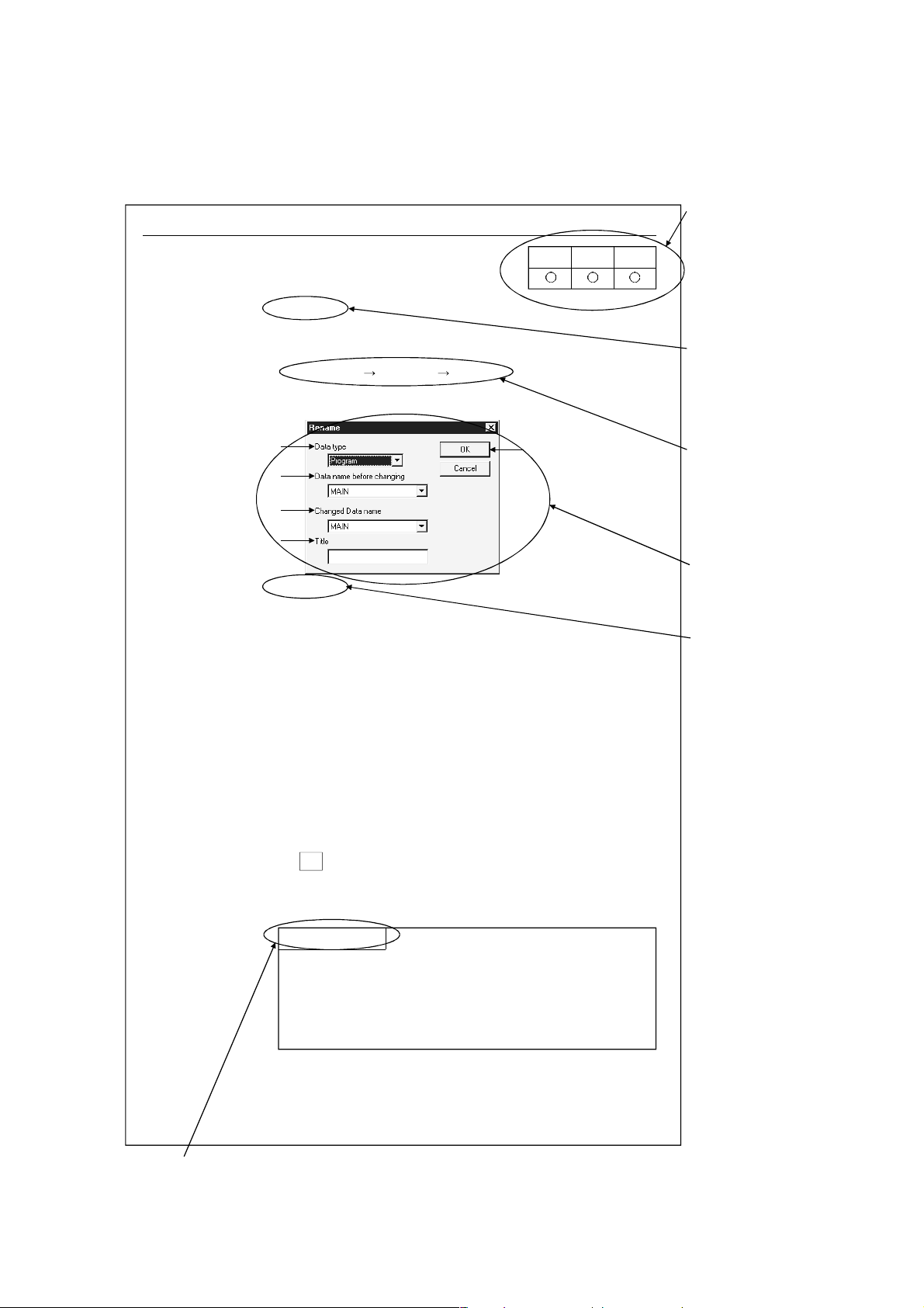
How the manual describes the explanation is shown below.
5.11 Renaming Data in a Project
[Purpose]
Renames the existing data in a project.
[Operating Procedure]
Select [Project] [Edit data] [Rename].
[Dialog Box]
1)
2)
3)
4)
[Description]
1) Data type
Designates the data type (program, common comment, comments
by program, device memory).
2) Data name before renaming
Designates the data name before renaming.
3) Renamed data name
Designates the new data name after renaming.
The data name must be designated in up to 8 characters.
4) Title
Displays the set title of the data.
If necessary, the title can be edited and stored.
It must be designated in up to 32 characters.
AQnAFX
5)
This table
indicates the
applicable items
for A series,
QnA series and
FX series.
Items which
are set in the
section are
explained.
The desired
window opens
by selecting
the items in the
specified order.
The dialog
boxes set in
the section
are explained.
The contents of
the items and
buttons are
explained.
The numbers
correspond to
those specified
in the window
shown under the
title of [Dialog box].
5) OK button
Click this button after making necessary settings.
POINT
This operation cannot change the data name of comments by
program to "COMMENT".
For changing the comments by program to the common
comment (COMMENT), refer to "Setting Comment Types"
(Section 9.6).
5 - 11
This gives the information related to the topic discussed and also the helpful information.
A - 14 A - 14
Page 16
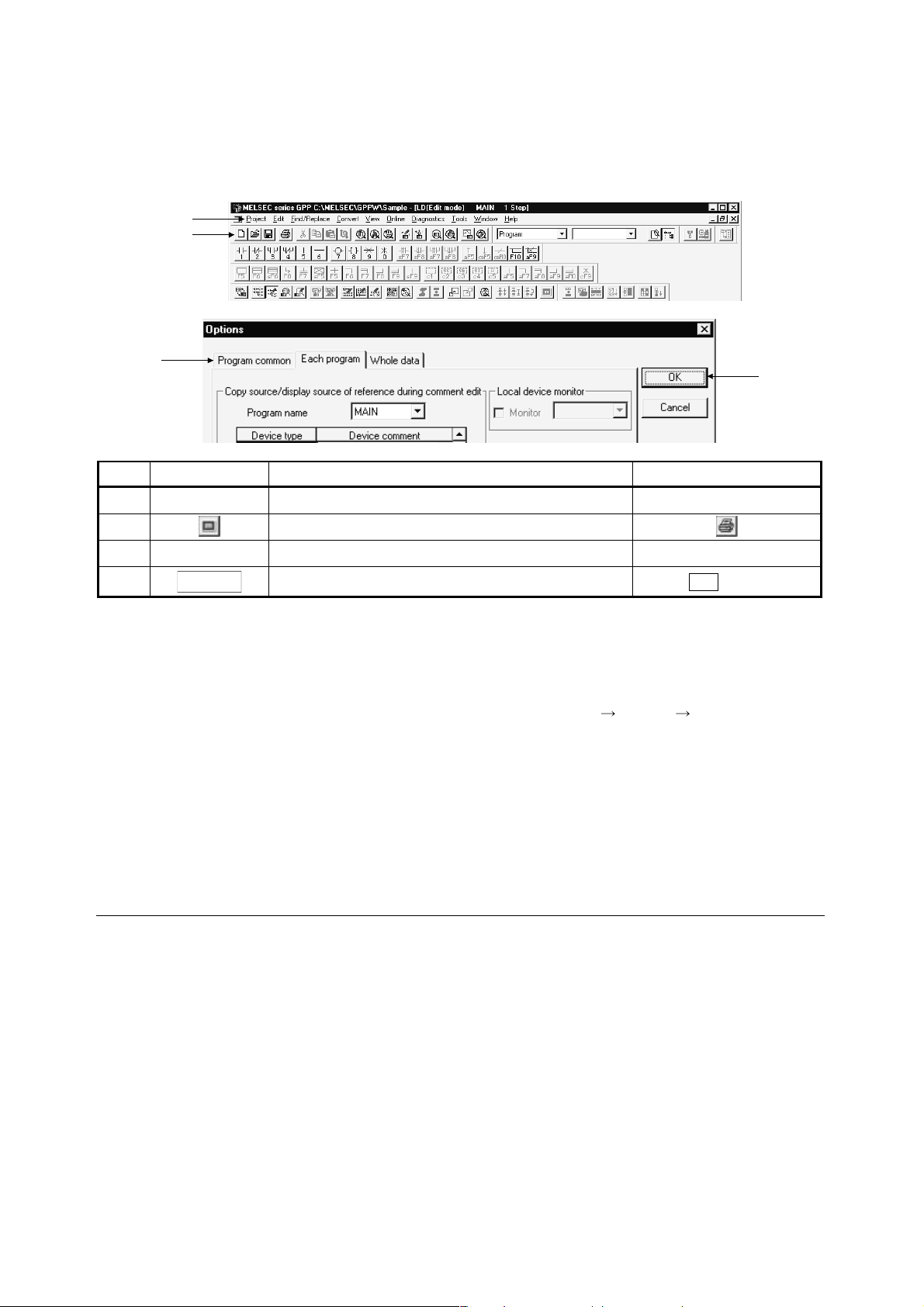
Symbols used in this manual, and the contents and examples of them are shown below.
1)
2)
3)
No. Symbol Contents Example
1) [ ] Menu name of menu bar [Project]
2) Icon in toolbar
3) << >> Tab name of dialog box <<Program common>>
lOKl
4) Command button in dialog box
button
4)
The functions that cannot be operated on GX Developer are grayed (masked) and
cannot be selected. There are the following reasons why they are not selectable.
(1) The PLC CPU used does not have the functions
For example, when the A1SCPU is chosen as the PLC type, it does not have
the STEP-RUN function and therefore [Online]
selected.
To see if your PLC CPU has the operable functions, check the specifications in
the PLC CPU user's manual or the like.
(2) The functions cannot be selected because they cannot be used with the currently
operated function
For example, when the monitor screen is open, PLC type change, connection
setup, PLC data attribute change, data coupling, parameter check and all
parameter clear cannot be performed.
Abbreviations and Terms in This Manual
This manual uses the abbreviations and terms listed in the following table to discuss
the GX Developer Software Package and PLC module. In addition, the following
table lists the names of modules whose names must be indicated explicitly.
[Debug] [Debug] cannot be
A - 15 A - 15
Page 17
Abbreviation/Generic Term Description/Target Module
Generic product name of the product types SWnD5C-GPPW-E, SWnD5C-GPPW-
GX Developer
EA, SWnD5C-GPPW-EV and SWnD5C-GPPW-EVA. (n denotes any of versions 0
to 6)
GX Developer (SWnD5CGPPW-E)
GX Developer (earlier than
SWnD5C-GPPW-E)
GX Developer (later than
SWnD5C-GPPW-E)
GX Simulator
GX Simulator (SWnD5C-LLTE)
GX Simulator (earlier than
SWnD5C-LLT-E)
GX Simulator (later than
SWnD5C-LLT-E)
When limited to the major version (n denotes the version number)
When limited to earlier than the major version (n denotes the version number)
When limited to later than the major version (n denotes the version number)
Generic product name of the product types SWnD5C-LLT-E, SWnD5C-LLT-EA,
SWnD5C-LLT-EV and SWnD5C-LLT-EVA. (n denotes any of versions 0 to 5)
When limited to the major version (n denotes the version number)
When limited to earlier than the major version (n denotes the version number)
When limited to later than the major version (n denotes the version number)
Generic term for PLC available with MELSEC-A
ACPU
Including MOTION (SCPU)
(However, GX Developer does not support A1, A2, A3, A3H, A3M, A52G, A73,
A0J2 and A3V.)
QCPU (A mode) Generic term for Q02(H)-A and Q06H-A
QnACPU Generic term for PLC available with MELSEC-QnA
QCPU (Q mode) Generic term for Q02(H), Q06H, Q12H and Q25H
Generic term for PLC available with MELSEC-F
FXCPU
(The target PLCs are FX0, FX0S, FX0N, FX1, FX, FX2, FX2C, FX1S, FX1N, FX2N
and FX2NC. )
AnNCPU A1NCPU, A2NCPU(S1), A3NCPU
AnACPU A2ACPU(S1), A3A
AnUCPU
A2UCPU(S1), A2USCPU(S1), A2ASCPU(S1), A2ASCPU-S30, A2ASCPU-S60,
A2USHCPU-S1, A3U, A4U
A series For GX Developer PLC type selection by ACPU
QnA series For GX Developer PLC type selection by QnACPU
Q series For GX Developer PLC type selection by QCPU (Q mode)
FX series For GX Developer PLC type selection by FXCPU
SW
GPPA
SW
SRXV-GPPA
IVD-GPPA
GPPQ SW IVD-GPPQ
MEDOC MELSEC-MEDOC
FXGP(DOS) SW1PC-FXGPEE/AT
FXGP(WIN) SW0PC-FXGP/WIN-E
SFC Generic term for MELSAP2/MELSAP3/MELSAP-L
Computer link
Unit
Serial
communication
unit
For A series
For AnU AJ71UC24, A1SJ71UC24-R2, A1SJ71UC24-R4, A1SJ71UC24-PRF
For QnA
series
For Q series Generic term for QJ71C24 and QJ71C24-R2
A1SJ71C24-R2, A1SJ71C24-R4, A1SJ71C24-PRF
A2CCPUC24(-PRF), A1SCPUC24-R2
Generic term for AJ71QC24, AJ71QC24-R2, AJ71QC24-R4, AJ71QC24N,
A1SJ71QC24, A1SJ71QC24-R2, AJ71QC24N-R2, AJ71QC24N-R4,
A1SJ71QC24N and A1SJ71QC24N-R2
C24 Computer link Unit, Serial Comunication Unit
QE71 AJ71QE71(B5), A1SJ71QE71-B2, A1SJ71QE71-B5
E71
AJ71AJ71E71-S3, A1SJ71E71-B2-S3, A1SJ71E71-B5-S3
A1SJ71E71-B2, A1SJ71E71-B5
Q series-compatible E71 Generic term for QJ71E71 and QJ71E71-B2
Ethernet board Ethernet PLC card, Ethernet I/F board
CC-Link Control & Communication Link
PLC PROGRAMMABLE LOGIC CONTROLLER
Personal computer
Personal computer compatible with Windows
Windows NT
®
Workstation 4.0
®
95/98 and
A - 16 A - 16
Page 18
1 GENERAL DESCRIPTION
MELSOFT
1. GENERAL DESCRIPTION
Product Outline and Features
Outline
This section explains GX Developer (unless otherwise specified, the product name represented GX
Developer will hereafter be its English version 6).
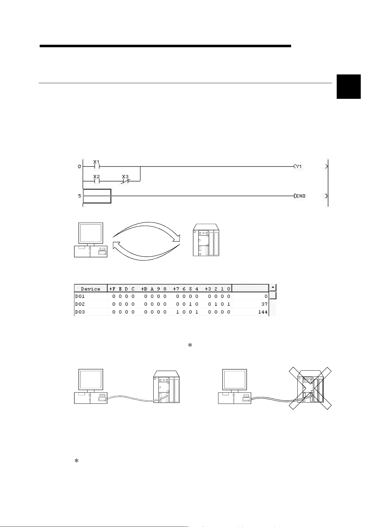
GX Developer is a software package having the following functions.
1. Program creation
2. Writing and reading to/from PLC
1
Writing
Reading
PLC
3. Monitoring (example: device batch monitoring)
The circuit monitor, device monitor, and device registration monitor can be used for monitoring.
4. Debugging
The created sequence program is written into PLC to test that the written sequence program
operates normally.
In addition, newly developed GX Simulator
represented GX Simulator will hereafter be its English version 5) can be used to debug the
program on a single personal computer.
PLC
1 (unless otherwise specified, the product name
PLC
5. Diagnostics PLC
The current error status, error status or error log can be displayed to shorten the time required
for error recovery.
Also, system monitoring (QCPU (Q mode) only) provides in-depth information on the special
functions. Therefore, if an error occurs, recovery work can be done in much shorter time.
: The logic test function (LLT) is an independent function and may be purchased separately.
1 - 1 1 - 1
Page 19

1 GENERAL DESCRIPTION
Features
GX Developer has the following features.
1
1. Common software
GX Developer can create the data of the Q series, QnA series, A series (including the motion controller
(SCPU)) and FX series, with their setting operations common, and is abbreviated to GPPA. Note that this
does not apply to the A6GPP/A6PHP-compatible software package. Data can be converted into an
SW
-GPPQ GPP function software package (hereafter abbreviated to GPPQ) format file and edited on
GPPA or GX-DEV.
When the FX series is selected, data can be converted into a DOS version programming software
(hereafter abbreviated to FXGP(DOS)) or SW0PC-FXGP/WIN programming software (hereafter
abbreviated to FXGP(WIN)) format file and you can edit data on FXGP(DOS) or FXGP(WIN).
2. Advantages of Windows are utilized for dramatic improvements in operability
Comment data created on Excel, Word or the like can be copied or pasted for data diversion.
3. Standardized programs
(1) Label programming
By using label programming to create sequence programs, you can create standard programs with
labels without being conscious of device numbers.
The programs created by label programming can be compiled for use as an actual program.
(2) Macros
By naming any ladder patterns (macro names) and registering them to a file (macro registration),
merely entering simple instructions allows the registered ladder patterns to be read and the devices to
be changed for data diversion.
MELSOFT
4. Ease of setting access to another station
As the connection target can be specified graphically, you can set access to another station easily if a
complicated system has been configured.
5. Connection with PLC CPU in any of various methods
(1) Via serial port
(2) Via USB
(3) Via MELSECNET/10(H) board
(4) Via MELSECNET/(II) board
(5) Via CC-Link board
(6) Via Ethernet board
(7) Via CPU board
(8) Via AF board
6. Fully useful debugging functions
(1) Use of the ladder logic test function (LLT) ensures much easier debugging.
(a) There is no need to make connection with the PLC CPU.
(b) There is no need to create a pseudo sequence program (debugging program).
(2) Containing the explanations of CPU errors and special relays/special registers, Help is useful when an
error has occurred online or when you want to know the contents of the special relays/special registers
during programming.
(3) If an error occurs during data creation, the corresponding message is displayed to indicate the cause
of that error, substantially reducing data creation time.
1 - 2 1 - 2
Page 20
1 GENERAL DESCRIPTION
MELSOFT
1.1 Functions Lists
The GX Developer functions are listed below.
The functions are divided into normally common functions (project, online, diagnosis,
tool, window, help) and functions for objects to be edited and set (edit,
search/replacement, conversion, display).
In addition, there are executable and inexecutable functions depending on the CPU
series.
POINTS
• The QCPU (A mode) and motion controller (SCPU) are described as the
ACPU.
• Refer to the corresponding manuals for details of the motion controller and
SFC.
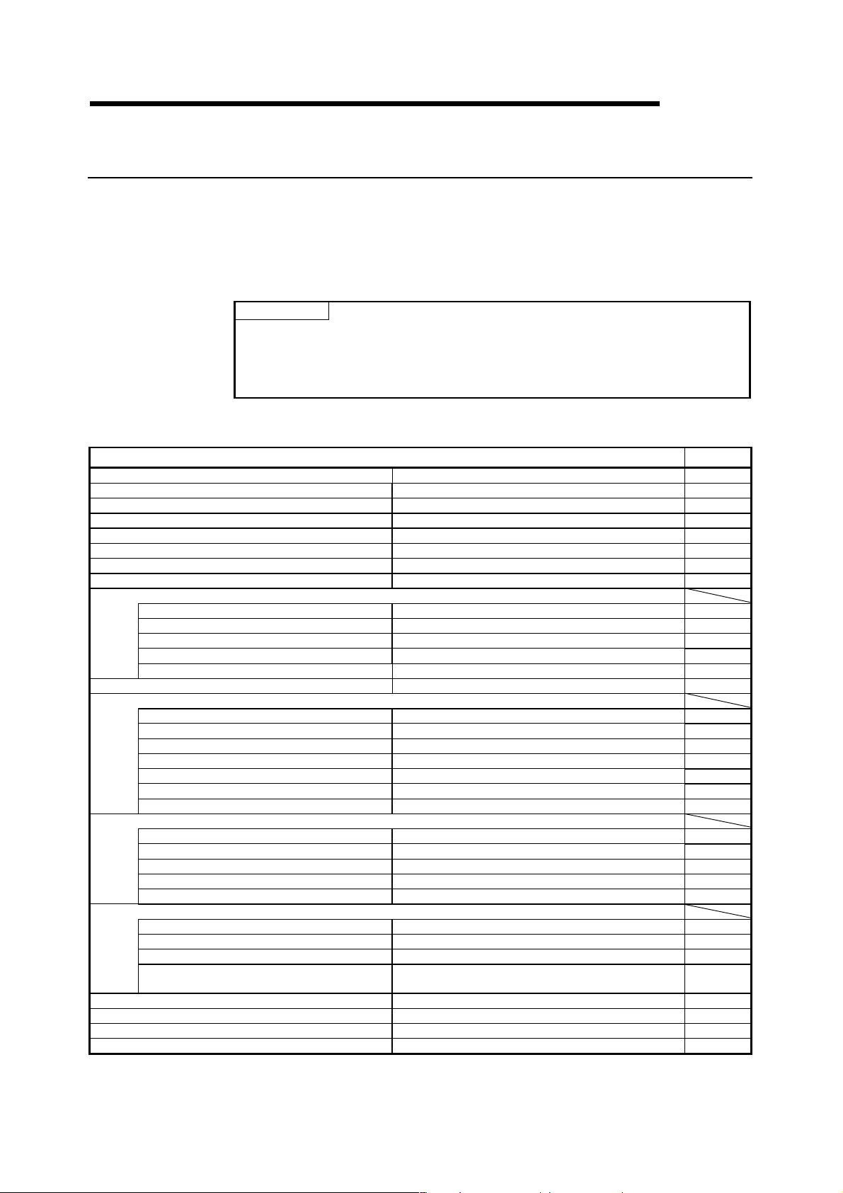
(1) List of common functions
Fixed functions independent of the type of the object being edited or set
Project (Common functions)
New project Creates a new project. 4.1
Open project Opens an existing project. 4.2
Close project Closes an open project. 4.3
Save Saves the project. 4.4
Save as Names and saves the project. 4.5
Delete project Deletes an existing project. 4.6
Verify Verifys data between projects. 4.7
Copy Copies data between projects. 4.8
Edit data
New Adds data to a project. (Except remote I/O) 4.9
Copy Copies data in a project. (Except remote I/O) 4.10
Delete Deletes data in a project. (Except remote I/O) 4.11
Rename Renames data in a project. 4.12
Change program type Change the program type in the project 4.13
Change PLC type Changes the PLC type. (Except remote I/O) 4.14
Import file
Import from GPPQ format file Read a GPPQ file (QnA only) 4.15.1
Import from GPPA format file Read a GPPA file (A only) 4.15.1
Import from FXGP(WIN) format file Read a FXGP(WIN) file (FX only) 4.15.1
Import from FXGP(DOS) format file Read a FXGP(DOS) file (FX only) 4.15.1
Import from Melsec Medoc format file (Print out) Import from Melsec Medoc format file (Print out) 4.15.2
Import from Melsec Medoc format file Import from Melsec Medoc format file 4.15.3
Import from MXChange tags Imports tags from MXChange Server 23.6
Export file
Export to GPPQ format file Write a GPPQ files (QnA only) 4.16
Export to GPPA format file Write a GPPA files (A only) 4.16
Export to FXGP(WIN) format file Write a FXGP(WIN) files (FX only) 4.16
Export to FXGP(DOS) format file Write a FXGP(DOS) files (FX only) 4.16
Export to MXChange tags Exports comment to MXChange Server 23.7
Macro
Registration macros Registration macros (Except remote I/O) 5.2.1
Macro utilize Macro utilize (Except remote I/O) 5.2.2
Delete macros Delete macro instruction from the file (Except remote I/O) 5.2.3
Macro reference path Set the macro instruction reference path
(Except remote I/O)
Printer setup Changes the printer settings. 14.1
Print Prints data. 14
Start new GX Developer session Restarts GX Developer. 4.17
Exit GX Developer Exits GX Developer. 4.18
Refer To
(To the next page)
5.2.4
1 - 3 1 - 3
Page 21
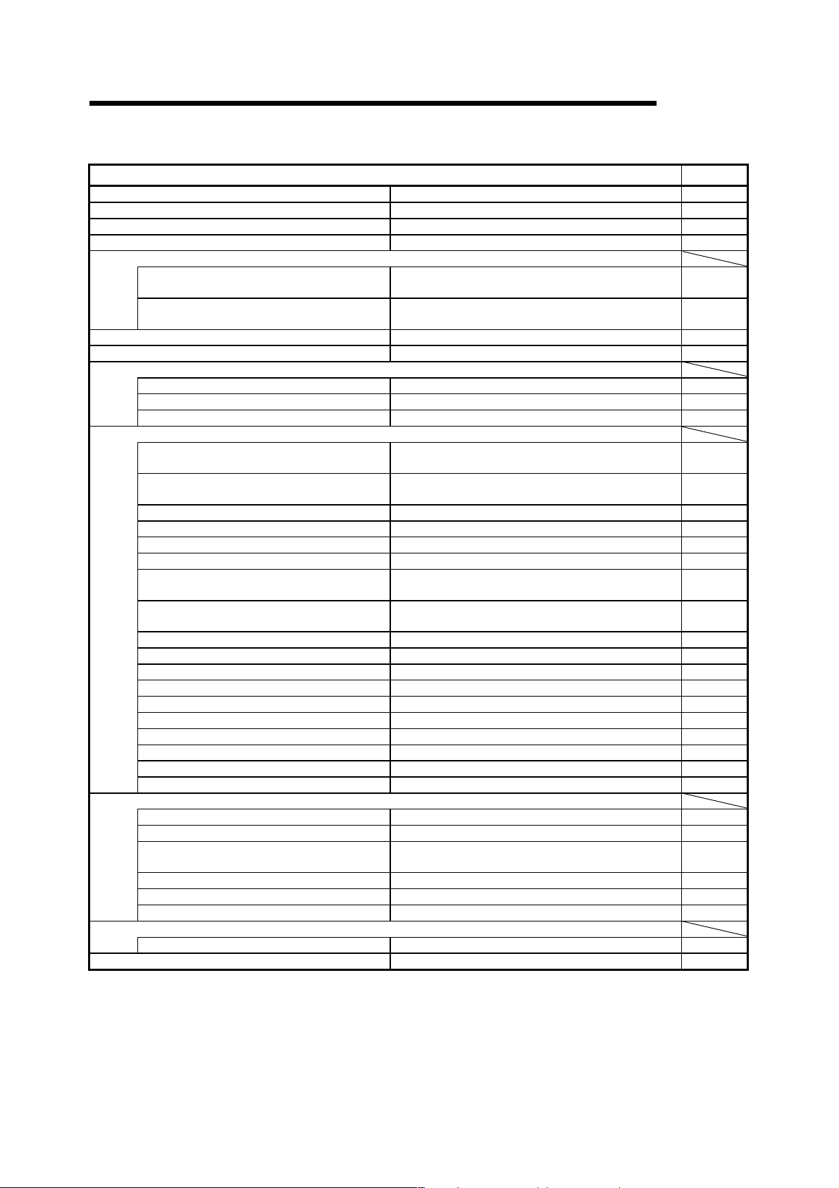
1 GENERAL DESCRIPTION
(Continued from the previous page)
Online (Common functions)
Transfer setup Designates a PLC destination from GX Developer. 16.1
Read from PLC Reads data from PLC. (Except label program) 16.3
Write to PLC Writes data to PLC. 16.3
Verify with PLC Verifys data with PLC data. 16.4
Write to PLC (Flash ROM)
Write the program memory to ROM
Write to PLC (Flash ROM)
Delete PLC data Deletes PLC data. (QnA only) 16.6
Change PLC data attributes Changes PLC data attributes. (QnA only) 16.7
PLC user data
Read PLC user data Reads user data from the PLC. (Q only) 16.8.1
Write PLC user data Writes user data to the PLC. (Q only) 16.8.2
Delete PLC user data Deletes user data of the PLC. (Q only) 16.8.1
Monitor
Monitor mode
Monitor (Write mode)
Start monitor (All windows) Starts monitoring all open windows. 17.2
Stop monitor (All windows) Stops monitoring all open windows. 17.2
Start monitor Restarts the stopped monitor. (Except remote I/O) 17.1
Stop monitor Stops the monitor. (Except remote I/O) 17.1
Change current value monitor (Decimal)
Change current value monitor (Hexadecimal)
Device batch Monitors devices in batch mode. 17.5
Entry data monitor Entry data mode 17.6
Buffer memory batch Monitors the buffer memory in batch mode. 17.5
Monitor condition setup Sets the monitor execusion conditions. (QnA only) 17.7
Monitor stop condition setup Sets the monitor stop conditions. (QnA only) 17.7
Program monitor list Monitors a program list. 17.8
Interrupt program monitor list Lists the interrupt programs. 17.9
Scan time measurement Measures the scan time. (Except remote I/O) 17.10
Entry ladder monitor Entry the ladder block (Except remote I/O) 17.12
Delete all entry ladder Delete all entry ladder (Except remote I/O) 17.13
Debug (ladder)
Device test Turns on or off the device or changes the vallue. 18.1
Forced input output registration/cancellation This will register the forced input output of device X/Y 18.2
Debug Executes/disables the debugging function.
Skip execution Makes settings for skip. (QnA, FX only) 18.5
Partial execution Makes settings for partial operation. (Except remote I/O) 18.3
Step execution Makes settings for step execution. (Except remote I/O) 18.4
Trace
Sampling trace Execute sampling trace. (Except remote I/O) 18.11
Remote operation Operates the PLC remotely. (Except remote I/O) 18.6
Writes program memory data to the standard ROM/IC
memory card (ROM). (Q only)
Writes data to the standard ROM/IC memory card
(ROM). (Q only)
Places the circle edit screen in monitor mode.
(Except remote I/O)
Sets the circuit (monitor write) mode.
(Except remote I/O)
Displays the current device value of the circuit monitor in
decimal form. (Except remote I/O)
Displays the current device value of the circuit monitor in
hexadecimal form. (Except remote I/O)
(Except remote I/O)
MELSOFT
Refer To
16.5.1
16.5.2
(To the next page)
17.1
17.3
17.4
17.4
18
1 - 4 1 - 4
Page 22

1 GENERAL DESCRIPTION
(Continued from the previous page)
MELSOFT
Online (Common functions) Refer To
Keyword/Password (Q series)
Register keyword Registers or changes the keyword. (Except remote I/O) 19
Delete keyword Cancels the keyword. (Except remote I/O) 19
Disable keyword Unlocks access by keywords (Except remote I/O) 19
Clear PLC memory Clears the PLC memory cassette or device memory.
(Except remote I/O)
Format PLC memory Formats the PLC memory. (QnA only) 20.2
Arrange PLC memory Arranges the data area within the PLC memory. (QnA only) 20.3
Set clock Sets the internal timer of the PLC. (Except remote I/O) 20.4
20.1
Diagnosis (Common functions) Refer To
PLC Diagnostics Diagnoses the PLC. (Except remote I/O) 21.1
Network diagnostics Diagnoses the network (A, QnA) 21.2
CC-Link diagnostics CC-Link diagnostics (A, QnA) 21.3
Ethernet diagnostics Diagnoses Ethernet. (Except FX) 21.4
System monitor Monitors the system status of the PLC. (Q only) 21.4
Tool (Common functions) Refer To
Check program Checks the program. (Except remote I/O) 15.1
Marge data Links data. (Except remote I/O) 15.2
Check parameter Checks the parameter. 15.3
Transfer ROM
Read Reads data from ROM. (A, FX) 15.8.1
Write Writes data to ROM. (A, FX) 15.8.1
Compare Compares data with ROM data. (A, FX) 15.8.1
Write to file Writes ROM data to files. (A, FX) 15.8.2
Delete unused comments Delete the comments which isn't used at program
Clear all parameters Deletes parameters. 15.4
IC memory card
Read IC memory card Reads data from the IC memory card. (Q only) 15.5.1
Write IC memory card Writes data to the IC memory card. (Q only) 15.5.2
Start ladder logic test Starts the ladder logic test. (Except remote I/O) 15.14
Set TEL data
Connection Connect the line for A6TEL/Q6TEL (Except remote I/O) 22.4
Disconnect Disconnect the line (Except remote I/O) 22.4.3
TEL data Set the report data of A6TEL or Q6TEL (FX, Except remote I/O) 22.3.3
AT command Entry the modem (Except remote I/O) 22.3.2
Call book Set the call book (Except remote I/O) 22.3.1
Intelligent function utility
Utility list
Session Starts the intelligent function utility. (Q, Remote I/O only) 15.7
MXChange actions Refer To
Log in Log in MXChange Server. 23.3
Log off Log off MXChange Server. 23.4
Change Password Changes password in MXChange Server. 23.3
Customize keys Changes key assignments for circuit symbol input. 15.9
Change display color The display color is changed (Except remote I/O) 15.10
Options Sets the options. (Except remote I/O) 15.11
Create start-up settings file Creates a file to save initial settings of the project.
Shows the utility names required to edit the intelligent function unit
parameters. (Q, Remote I/O only)
(Except remote I/O)
(Except remote I/O)
15.9
15.7
15.13
Window (Common functions) Refer To
Cascade Cascades windows. 15.12
Tile vertically Tiles the windows vertically. 15.12
Tile holizontally Tiles the windows horizontally. 15.12
Arrange icons Arranges the icons in the lower part of the window. 15.12
Help (Common functions) Refer To
CPU error Displays the description of each CPU error code. 15.15
Special relay/register Displays the description of special relays or registers. 15.15
Key operation list Displays the description of each key operation. 15.15
Product information Displays product information (such as version number). 15.15
Connect to MELFANSweb Connect to MELFANSweb 15.15
1 - 5 1 - 5
Page 23
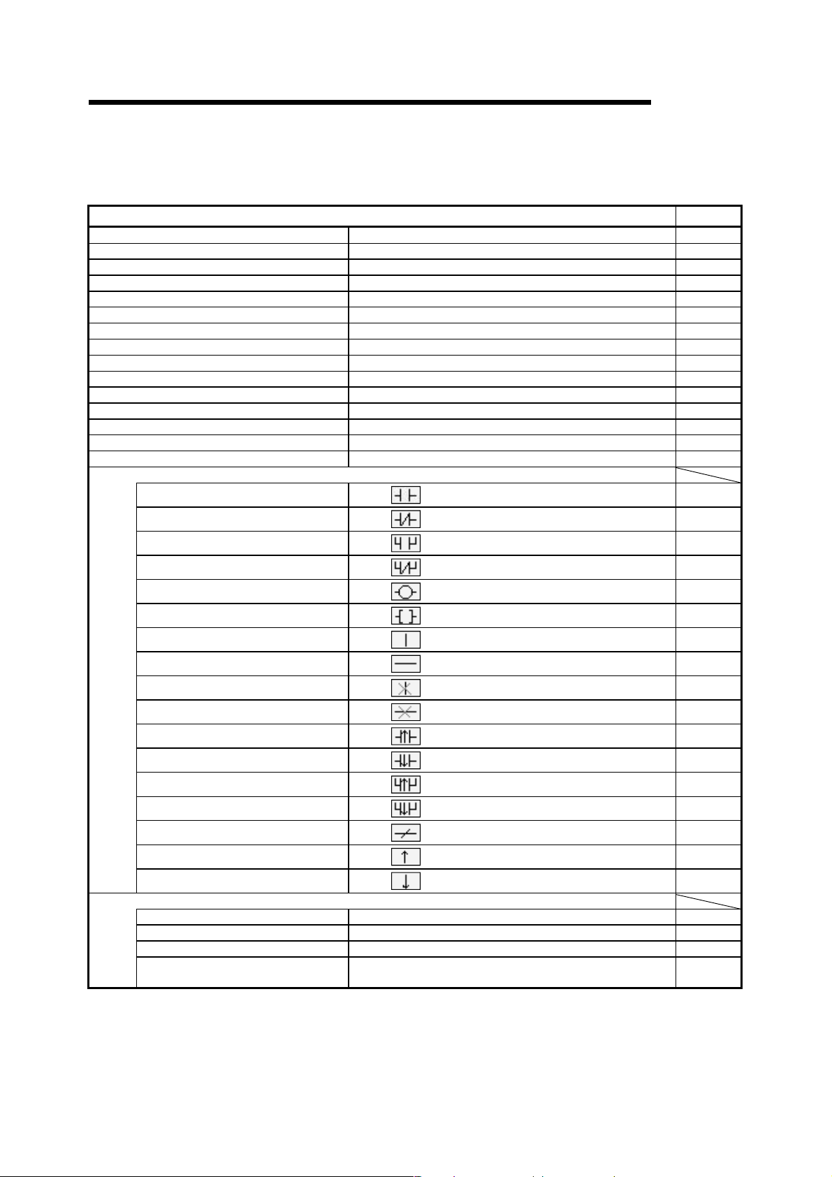
1 GENERAL DESCRIPTION
(2) Ladder editing function list
The following functions can be performed to edit the ladders and operation
outputs/transition conditions.
MELSOFT
Edit (Ladder editing functions)
Undo Reverses the last operation. 6.2.9
Cut Moves the selected data to the Clipboard. 3.3.1
Copy Copies the selected data to the Clipboard. 3.3.2
Paste Pastes the contents of the Clipboard at the cursor position. 3.3.1
Insert line Inserts a row at the cursor position. 6.2.5
Delete line Deletes a row at the cursor position. 6.2.5
Insert row Inserts a column at the cursor position. 6.2.5
Delete row Deletes a column at the cursor position. 6.2.5
Insert NOP batch Inserts NOP before a circuit block at the cursor position. 6.2.6
Delete NOP batch Deletes all NOPs in the program at a time. 6.2.7
Draw line Inserts a line. 6.2.2
Delete line Deletes a line. 6.2.4
Change TC setting Changes the setting value of the timer or counter. 6.3
Read mode Places the circuit screen in the read mode. 6
Write mode Places the circuit screen in write mode. 6
Ladder symbol
Open contact
Close project contact
Open branch
Close project branch
Coil
Application instruction
Vertical line
Horizontal line
Delete vertical line
Delete Horizontal line
Rising pulse
Falling pulse
Rising pulse Open branch
Falling pulse Close branch
Invert operation results
Convert operation results to rising pulse
Convert operation results to falling pulse
Documentation
Comment Edits the comment at the cursor position. 9.4.4
Statement Edits the statement in the ladder at the cursor position. 10.3.1(1)
Note Edits the note in the ladder at the cursor position. 10.4.1(1)
Statement/Note block edit
Inserts
Inserts
Inserts
Inserts
Inserts
Inserts
Inserts
Inserts
Inserts
Inserts
Inserts
Inserts
Inserts
Inserts
Inserts
Inserts
Inserts
The statement and note under the program is edited by the
batch.
at the cursor position.
at the cursor position.
at the cursor position.
at the cursor position.
at the cursor position.
at the cursor position.
at the cursor position.
at the cursor position.
at the cursor position.
at the cursor position.
at the cursor position. (QnA, FX)
at the cursor position. (QnA, FX)
at the cursor position. (QnA, FX)
at the cursor position. (QnA, FX)
at the cursor position. (QnA, FX)
at the cursor position. (QnA, FX)
at the cursor position. (QnA, FX)
Refer To
6.2
6.2
6.2
6.2
6.2
6.2
6.2
6.2
6.2
6.2
6.2
6.2
6.2
6.2
6.2
6.2
6.2
10.5
1 - 6 1 - 6
Page 24
1 GENERAL DESCRIPTION
MELSOFT
Search/Replacement (Ladder editing functions)
Find device Searches for a device. 6.4.1
Find instruction Searches for an instruction. 6.4.2
Find step No. Searches for a step number. 6.4.3
Find character string Searches for a character string in comment, note, or statement. 6.4.4
Find contact or coil Find contact or coil 6.4.5
Finding data Finding data 6.4.6
Replace device Searches for and replaces a device. 6.4.7
Replace instruction Searches for and replaces an instruction. 6.4.8
Change open/close contact Searches for and replaces a contact a with a contact b. 6.4.9
Replace character string
Chang module start address
Replace statement/note type
Replacing data Replacing data 6.4.13
Cross referense list Finds whether the device is being used by a contact or coil. 6.4.14
List of used devices Finds where the device is used. 6.4.15
Searches for and replaces a character string in comment, note, or
statement.
This will exchange the starting address of the buffer memory
access instruction
Searches for and replaces the type of a character string between
statement and note. (Q, QnA only)
Conversion (Ladder editing functions)
Convert Converts the program. 8.1
Convert (All programs being edited) Converts the programs (not converted yet) in all windows. 8.2
Convert block (Online change) Converts the program and writes it during run. 16.9
Display (Ladder editing functions)
Comment Displays or hides comments. 3.8
Statement Displays or hides statements. 3.9
Note Displays or hides notes. 3.10
Device Label Displays or hides device names. 3.11
Macro instruction format display Provides display in the user macro instruction format. (Except FX) 5.16
Comment format
4 × 8 characters Shows comments in 4 × 8 or 2 × 8 characters. 3.12
3 × 5 characters Shows comments in 3 × 5 characters. 3.12
Alias display format
Displayed instead of device Displays the machine name at the device name display position. 3.13.1
Displayed with device Arrange and displays the machine name above the device name. 3.13.2
Toolbar Displays of hides the toolbar. 3.4
Status bar Displays of hides the status bar. 3.5
Zoom
50% Displays a circuit reduced to 50%. 3.6
75% Displays a circuit reduced to 75%. 3.6
100% Displays a full-size circuit. 3.6
150% Displays a circuit magnified to 150%. 3.6
Auto Displays a circuit according to the screen size. 3.6
Project data list Displays or hides the project data list. 3.7
Instruction list Switches program circuit display and list display. 6
Elapsed time Displays the elapsed time. 22.4.1
Refer To
6.4.10
6.4.11
6.4.12
Refer To
Refer To
(3) Device comment editing function list
The following functions can be performed to edit device comments.
Edit
Clear all (all devices) Deletes the comments or device names of all devices. 9.5.1
Clear all (displayed devices) Deletes the displayed comments or device names. 9.5.2
Setup comment Sets the common comments or comments by program. 9.6
Setup comment range Sets a comment range. 9.7
Refer To
1 - 7 1 - 7
Page 25
1 GENERAL DESCRIPTION
MELSOFT
(4) Device memory setting function list
The following functions can be performed to set the device memory.
Edit
Clear all (all devices) Deletes data of all devices. 11.3.1
Clear all (displayed devices) Deletes the data of displayed devices. 11.3.2
FULL Sets all data to the specified value. 11.4
Refer To
(5) Label programming function list
The following functions are available for label program editing.
Editing (Functions for label program editing)
Auto device setting Setting auto device 5.1.4
Global variable setting Setting global variable 5.1.3
Local variable setting Setting local variable 5.1.3
Editing (Functions for local label variable/global label variable editing)
Insert line Inserts a line at the cursor position 5.1.3
Add line Adds a line under the cursor position 5.1.3
Delete line Delete a line from the cursor position 5.1.3
Delete auto External Delete all Auto External 5.1.5
Delete all Delete all variables 5.1.6
Auto device setting Setting auto device 5.1.4
Global variable setting Setting global variable 5.1.3
Import the device comment Import the device comment (local label variables only) 5.1.7
Export the device comment Export the device comment 5.1.8
Conversion (Functions for label program editing)
Compile Compile the label program 5.1.9
Compile (All programs being edited) Compile the all the not compiled label programs 5.1.9
Compile (All programs) Compile the all label programs 5.1.9
Tool
Sort 5.1.3
Label order Sort by label 5.1.3
Device/Constant order Sort by Device/Constant 5.1.3
Device type order Sort by Device type 5.1.3
Refer To
Refer To
Refer To
Refer To
(6) SFC editing function list
The following functions can be performed to edit SFC.
For details, refer to the GX Developer Version6 operating manual (SFC
manual).
Edit (SFC editing functions)
Insert line Inserts a row at the cursor position.
Delete line Deletes a row at the cursor position.
Insert row Inserts a column at the cursor position.
Delete row Deletes a column at the cursor position.
Edit the line
Vertical line Writes a vertical line.
Selection divergence Writes selective branch.
Simultaneous divergence Write a parallel branch.
Selection convergence Writs a selective coupling.
Simultaneous convergence Writes a parallel coupling.
Delete the line Deletes the selective/parallel branch or selective/parallel coupling.
Change TC setting Changes the setting value of the timer or counter.
Read mode Places the circuit screen in the read mode.
Write mode Places the circuit screen in write mode.
Step attribute
Normal Set the normal (A/Q/QnA)
Stored coil Set the stored coil (SC) type (A/Q/QnA)
Stored operation (without transition check) Stored operation (without transition check) [SE] type (Q/QnA)
Stored operation (with transition check) Set the stored operation (with transition check) [ST] type (Q/QnA)
Reset Set the reset [R] type (Q/QnA)
(To the next page)
1 - 8 1 - 8
Page 26
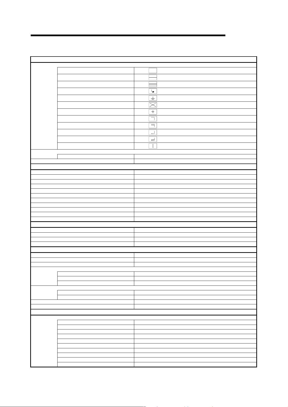
1 GENERAL DESCRIPTION
(Continued from the previous page)
MELSOFT
Edit (SFC editing functions)
SFC symbol
Step
Block START step (with END check)
Block START step (without END check)
Jump
End step
Dummy step
Transition
Selection divergence
Simultaneous divergence
Selection convergence
Simultaneous convergence
Vertical line
Documentation
Comment Edit comment
Block information Set the block information
Inserts
Inserts
Inserts
Inserts
Inserts
Inserts
Inserts
Inserts
Inserts
Inserts
Inserts
Inserts
at the cursor position.
at the cursor position. (A/Q/QnA)
at the cursor position. (Q/QnA)
at the cursor position.
at the cursor position. (A/Q/QnA)
at the cursor position. (A/Q/QnA)
at the cursor position.
at the cursor position.
at the cursor position.
at the cursor position.
at the cursor position.
at the cursor position.
Search/Replacement (SFC editing functions)
Find device Finds device.
Find instruction Finds instruction.
Find step No./block No. Finds the step number.
Find character string Finds character string.
Replace device Replaces a device.
Replace instruction Replaces an instruction.
Change open/close contact Replaces open/close contact.
Replace step No. Replace the step number
Replace character string Replaces a character string.
Cross reference list Finds whether the device is being used by a contact or coil.
List of used devices Finds where the device is used.
Conversion (SFC editing functions)
Convert (All programs being edited) Converts the programs (not converted yet) in all windows.
Convert (block) Convert the block data
Convert block (all block) Convert the all block
Display convert error Display the convert error
Display (SFC editing functions)
Display comment of step and TR Displays the step and transition comment.
Display label of step and TR Displays the step and transition label.
Row of SFC Set the row number of SFC diagram.
Zoom setting
Set the contact at right
Review SFC Review SFC
Display block list Display block list
Below Display the zoom ladder of list at below
Right Display the zoom ladder of list at right
Split Display the zoom ladder of list
5 contacts Display 5 contacts at the line of ladder
11 contacts Display 11 contacts at the line of ladder
Online (Common functions)
Debug (SFC)
Device test Sets the device value.
Block brake Block brake (A/Q/QnA)
Step brake Step brake
Block run Block run
Step run Step run
1 step run 1 step run
Block forced stopping Block forced stopping
Step forced stopping Step forced stopping
Reset stored step Reset stored step
Run all block Run All Block
1 - 9 1 - 9
Page 27

1 GENERAL DESCRIPTION
1.2 FX Series Programming
MELSOFT
This section describes the main differences between the GX Developer operating
environment and FX-dedicated programming software (DOS
version) operating environment and the points to be noted.
Target PLC:
FX
0, FX0S, FX0N, FX1, FX2, FX2C, FX1S, FX1N, FX2N, and FX2NC series
In the selection of PLC type, select FXU/FX
See Section 2 for details on the system configuration and connection method.
Operating Environment
• Differences of main terms
⋅ Program file handling
GX Developer programming data is created in units of folders (directories) called
the projects.
FXGP(DOS) and FXGP(WIN) do not have the concept of project, and program
files are created in any folders (directories) for management.
For this reason, the program file names in FXGP(DOS) and FXGP(WIN) are
project names in GX Developer.
For details on project specification, see Section 3.2.
⋅ Comments
(1) The number of characters that can be input may be different (see Appendix
11).
(2) The circuit comment is called the statement.
(3) The coil comment is called the note.
2C for FX,FX2 and FX2C
®
version, Windows
®
⋅ Parameter settings
Some setup screens have different names (see Section 13).
• Differences in operations
⋅ Step ladder instructions (STL, RET) are displayed in different ways (see Section
6.1.2).
⋅ Monitor display may be partially different (see Appendix 11).
⋅ Application instructions using the FNC. No. are not available.
⋅ Although FX PLC operates in the sequence program with no End instructions,
END instructions are forceful input in GX Developer.
1 - 10 1 - 10
Page 28

1 GENERAL DESCRIPTION
• Common items and others
⋅ Items that are available for only A series or QnA series are disabled and
displayed in gray in the GX Developer operation screens.
⋅ Partial execution, step run, and step run debug functions cannot be used when
FXCPU is connected. However, these debug functions can be used for
debugging with a single personal computer when the GX Simulalor is connected
(see Chapter 18 for details).
⋅ The program conversion function is provided for conversion from A to FX series
and vice versa (see Section 4.13 and Appendix 4 for details).
⋅ The GX Developer FX series allows users to create only one program file.
Because A series or QnA series allows users to create multiple program files,
this manual may use screen examples including multiple program files when
describing the function. However, when FX series is selected, only the main
program is displayed on the screen.
⋅ The connection cable and RS-232C/RS-422 converter for FX PLC may be
different from those for A or QnA series PLC (see Subsection 2 for details).
MELSOFT
⋅ GX Developer is cable of reading from or writing to FXGP(DOS) and
FXGP(WIN) files basically. However, note that there are some exceptions (see
Sections 4.14 and 4.15 and Chapter 9 for details).
⋅ SFC program of FX series is displayed as STL and RET instructions on the
circuit edit screen of the GX Developer since the program is described as the
step ladder instructions.
It is possible to edit on the circuit.
1 - 11 1 - 11
Page 29
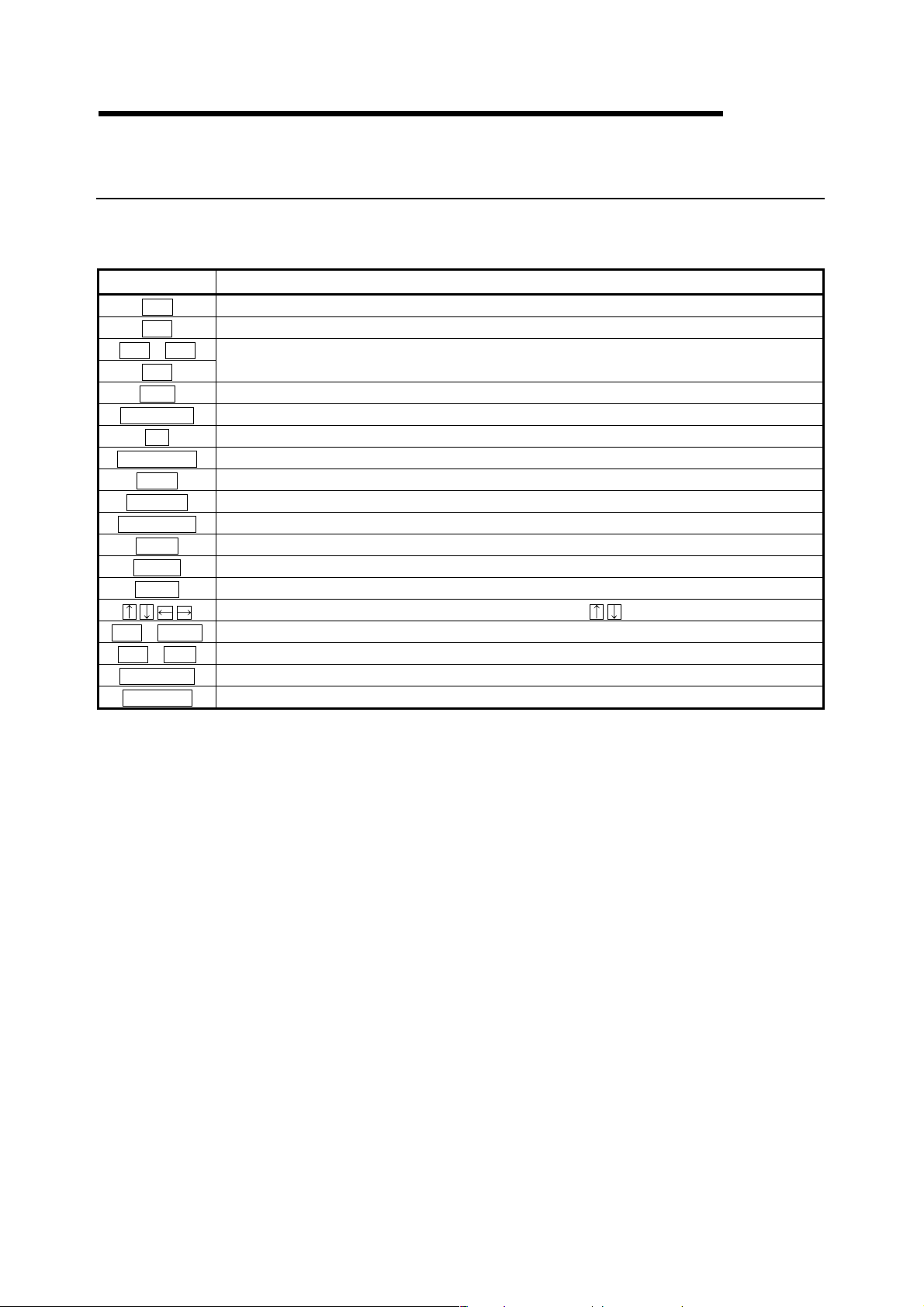
1 GENERAL DESCRIPTION
1.3 Basic Key Specifications
The following table summarizes the purposes of the keys used with the GX
Developer.
Key Name Purpose
Escl
Ta bl
Ctrl + Tabl
Ctrll Used in a combination with a alphanumeric key or a function key.
Shiftl
Caps Lockl
Altl
Back spacel
Enterl
Page Upl
Page Downl
Insertl
Deletel
Homel
Ctrl + Homel
Ctrl + Endl
Scroll Lockl
Num Lockl
Closes the window, interrupts execution, and selects instructions.
Enters a tab code and switches the target to which the cursor must be moved quickly.
Selects a character at the Shift position.
Switches upper-case and lower-case letters.
Selects the menu.
Deletes a character to the left of the cursor position.
Enters a carriage return.
Scrolls down the circuit or list by page. (Scrolls a screen in minus direction.)
Scrolls up the circuit or list by page. (Scrolls a screen in plus direction.)
Enters a space character at the cursor position.
Deletes a character at the cursor position. (Clears all settings.)
Moves the cursor to the home position.
Moves the cursor or scrolls the circuit or list in unit of lines. ( )
Moves circuit the cursor to step 0 in the mode.
Moves the cursor to the End instruction in the circuit mode.
Inhibits scroll-up and scroll-down.
Uses the Ten-key pad for numeric key input only.
MELSOFT
1 - 12 1 - 12
Page 30

2 SYSTEM CONFIGURATION
2. SYSTEM CONFIGURATION
2.1 Connection from the Serial Port
MELSOFT
GX Developer
(SW6D5C-GPPW-E)
SW6D5F-GPPKEY-E
The following system configuration is made up by connection from the serial port.
USB communication
Serial port communication
5
Computer link
CC-Link (via G4)
MELSECNET(II)
3
Converter/cable
3
Converter/cable
1
USB cable
See Appendix-3
RS-232C
2
QC30R2
3
Converter/cable
3
Converter/cable
G4 module
G4-S3 module
C24
CC-Link
QCPU (Q mode)
QCPU (Q mode)
QCPU (A mode)
FXCPU
ACPU
QnACPU
ACPU
QnACPU
2
ACPU
QnACPU
QCPU (Q mode)
QCPU (A mode)
QCPU (Q mode)
QCPU (A mode)
MELSECNET/10
MELSECNET/H
Via modem
Modem
3
Converter/cable
4
Cable supplied with modem
4
Cable supplied with modem
Remote station
Remote station
Modem
Remote unit
Remote unit
A6TEL/Q6TEL
C24
Master station
Control station
ACPU
QnACPU
QnACPU
QCPU (Q mode)
QCPU (A mode)
FX2N series
2 - 1 2 - 1
Page 31

2 SYSTEM CONFIGURATION
MELSOFT
1: About the USB cable (QCPU (Q mode) compatible)
(1) Usable when Windows
(2) Unusable for Windows
(3) Use of the USB cable allows only one PLC CPU to be connected.
(4) Use the USB cable which conforms to the USB Standard Rev. 1.1.
(5) Refer to POINT in Section 16.1 for precautions for and restrictions on using
the USB cable to make communications.
2
2: About the cable (QCPU (Q mode), QCPU (A mode) compatible)
For communication in 115.2/57.6kbps
Fast communication cannot be made if the Personal computer used is not
compatible with the communication speed of 115.2/57.6kbps.
If a communication error occurs, reduce the baud rate setting and restart
communication.
The following cable has been confirmed by Mitsubishi Electric that it will work
properly.
Using the cable of Mitsubishi Electric make
QC30R2 (when Personal computer connector is D-sub, 9-pin)
®
98 and USB driver have been installed.
®
95,Windows NT® Workstation 4.0.
RS-232 cable
Personal computer Side
(RS-232C cable)
F2-232CAB-1
(when Personal computer
connector is D-sub, 9-pin)
3: About the converter/cable (ACPU, QnACPU, FXCPU compatible)
(1) Using the products of Mitsubishi Electric make
RS-232C/RS-422
Converter
FX-232AW(C)
For ACPU, QnACPU, FX1/FX2CPU/FX2CCPU
FX-422CAB (0.3m)
FX-422CAB-150 (1.5m)
0/FX0S/FX0N/FX1S/FX1N/FX2N/FX2NCCPU
For FX
FX-422CABO (1.5m)
PLC CPU Side
(RS-422 cable)
2 - 2 2 - 2
Page 32

2 SYSTEM CONFIGURATION
)
• How to identify compatibility of the F2-232CAB and F2-232CAB-1 cables with the
ACPU and QnACPU
Check the indication of the model label attached to the cable.
MELSOFT
Incompatible products
F2-232CAB
Y990C
F2-232CAB-1
Y990C
Compatible products (with indication of F/FX/A
F2-232CAB(F/FX/A)
Y990C
F2-232CAB-1(F/FX/A)
Y990C
4: About the modems relayed
Use the straight cables supplied with the modems.
5: About computer link
When the A series is used for communication via the C24/UC24, the program
which uses V, Z (index qualification) cannot be monitored.
2 - 3 2 - 3
Page 33

2 SYSTEM CONFIGURATION
2.2 Connection from the Interface Boards
The following system configuration is made up by connection from the interface
boards.
Refer to the corresponding board manuals for the way to connect the boards and
install the drivers.
1
MELSECNET/10 board
Personal computer
A70BDE-J71QLP23
(Optical loop)
A70BDE-J71QLP23GE
(Optical loop)
A70BDE-J71QBR13
(Coaxial bus)
A70BDE-J71QLR23
(Coaxial Loop)
MELSECNET/H board (future plan)
Personal computer
GX Developer
(SW6D5C-GPPW-E)
SW6D5F-GPPKEY-E
Q80BD-J71BR11
(Coaxial loop)
Q80BD-J71LP21-25
(Optical loop)
2
CC-Link board
A80BDE-J61BT13
A80BDE-J61BT11
3
Ethernet board
Commercially available
Ethernet board
Driver
Personal computer
SW3DNF-MNET10
Driver
SW0DNC-MNETH-B
Driver
SW3DNF-CCLINK
Driver
Driver supplied with
commercially available
Ethernet board
MELSOFT
ACPU
QnACPU
QCPU (Q mode)
QCPU (A mode)
Other station PLC
ACPU
QnACPU
QCPU (Q mode)
QCPU (A mode)
Other station PLC
ACPU
QnACPU
QCPU (Q mode)
QCPU (A mode)
Other station PLC
ACPU
QnACPU
QCPU (Q mode)
QCPU (A mode)
Other station PLC
CPU board
A80BDE-A2USH-S1
Driver
SW0DNF-ANU-B
1: MELSECNET/10 board
If a communications error takes place, an error code is indicated in the least
significant 4 digits.
Refer to the error code list of the MELSECNET/10 board manual.
2: CC-Link board
Accessible only when the CC-Link board is set as the local station.
3: Ethernet board
(1) The following Ethernet boards/cards have been confirmed by Mitsubishi Electric
to operate properly.
Maker Name Model
3COM make Ethernet Link III LAN PC Card
Ethernet board/card
Allied Telesis make
TDK make
Center COM LA-PCM Ethernet PC Card
LAN Adapter
10BASE-T LAN card
(Model: LAN-CD021BX)
Ethernet board Allied Telesis make RE2000 (ISA)
2 - 4 2 - 4
Page 34

2 SYSTEM CONFIGURATION
2.3 System Equipment Lists
(1) The following list indicates module connectable from the serial port.
PLC Series Module Name Module Model
A0J2H, A1S(S1), A1FX, A1SJ, A1SH, A1SJH, A1N,
PLC CPU module
A series
QnA series
Q series
FX series PLC CPU module FX0(S), FX0N, FX1, FX2(C), FX1S, FX1N, FX2N(C)
Computer link module 1
MELSECNET(II) data link remote I/O module AJ72P25, AJ72R25
MELSECNET/B data link remote I/O module AJ72T25B, A1SJ72T25B
MELSECNET/10 network remote I/O module AJ72LP25, QJ72LP25, QJ72BR15
CC-Link G4 module AJ65BT-G4, AJ65BT-G4-S3
PLC CPU module Q2A, Q2AS(H), Q2AS1, Q2AS(H)S1, Q3A, Q4A, Q4AR
Serial communication module 2
MELSECNET/10 network remote I/O
module
CC-Link G4 module AJ65BT-G4, AJ65BT-G4-S3
PLC CPU module Q02(H), Q06H, Q12H, Q25H
Serial communication module 3 QJ71C24, QJ71C24-R2
MELSECNET/H network remote I/O module QJ72LP25, QJ72BR15
G4 module AJ65BT-G4-S3
A2C, A2CJ, A2N(S1), A2S(S1), A2SH(S1), A171SH,
A172SH, A3N, A2A(S1), A3A, A2U(S1), A2US(S1),
A2AS(S1), A2AS-S30, A2AS-S60, A2USH-S1, A3U,
A4U, A173UH(S1), A273UH(S3), Q02(H)-A, Q06H-A
AJ71UC24, A1SJ71UC24-R2, A1SJ71UC24-PRF,
A1SJ71UC24-R4, A1SJ71C24-R2, A1SJ71C24PRF,
A1SJ71C24-R4, A1SCPUC24-R2, A2CCPUC24,
A2CCPUC24-PRF
AJ71QC24, AJ71QC24-R2, AJ71QC24-R4,
AJ71QC24N, A1SJ71QC24, A1SJ71QC24-R2,
AJ71QC24N-R2, AJ71QC24N-R4, A1SJ71QC24N,
A1SJ71QC24N-R2
AJ72QLP25, AJ72QBR15, A1SJ72QLP25,
A1SJ72QBR15, QJ72LP25, QJ72BR15
MELSOFT
(2) The following table indicates the modules which can be connected from the
MELSECNET/10 or MELSECNET/H (MELSECNET/10 mode) (future plan)
board.
PLC Series Module Name
A series AJ71LP21, AJ71BR11, A1SJ71LP21, A1SJ71BR11
QnA series AJ71QLP21, AJ71QBR11, A1SJ71QLP21, A1SJ71QBR11
Q series
QJ71LP21, QJ71BR11
QJ71LP21, QJ71BR11, QJ71LP21-25
(3) The following table indicates the modules which can be connected from the
MELSECNET/H board. (Future plan)
PLC Series Module Name
Q series QJ71LP21, QJ71BR11, QJ71LP21-25
(4) The following list indicates modules connectable from the CC-Link board.
Module Name
A series AJ61BT11, A1SJ61BT11
QnA series AJ61QBT11, A1SJ61QBT11
Q series QJ61BT11
(5) The following list indicates modules connectable from the Ethernet board.
Module Name
A series AJ71E71-S3, A1SJ71E71-B2-S3, A1SJ71E71-B5-S3, A1SJ71E71-B2, A1SJ71E71-B5
QnA series AJ71QE71, AJ71QE71-B5, A1SJ71QE71-B2, A1SJ71QE71-B5
Q series QJ71E71, QJ71E71-B2
2 - 5 2 - 5
Page 35

2 SYSTEM CONFIGURATION
1: About the computer link module
Note that when the PLC CPU is accessed from the personal computer via
the computer link module, the modules that may be connected directly with
the personal computer are limited.
If the module cannot be connected directly with the personal computer, it
may be usable as the "n"th module of multidropping.
MELSOFT
Type Interface
AJ71UC24
AJ71C24-S6
AJ71C24-S8
A1SJ71UC24-R2 RS-232C
A1SJ71C24-R2 RS-232C
A1SJ71UC24PRF
A1SJ71C24-PRF RS-232C
A1SJ71UC24-R4 RS-422/485
A1SJ71C24-R4 RS-422/485
A1SCPUC24-R2 RS-232C
A2CCPUUC24PRF
RS-232C
RS-422/485
RS-232C
RS-422
RS-232C
RS-422
RS-232C
RS-232C
RS-422A2CCPUC24
RS-422/485
RS-232C
RS-422
RS-422/485
1:1
Connection
Multidropping
First module "n"th module
2 - 6 2 - 6
Page 36

2 SYSTEM CONFIGURATION
2: The following table indicates whether the interfaces may be connected to
the personal computer when the PLC CPU is accessed from the personal
computer via the serial communication module (QC24).
If the module cannot be connected directly with the personal computer, it
may be usable as the "n"th module of multidropping.
MELSOFT
Type Interface
AJ71QC24
AJ71QC24N
AJ71QC24-R2
AJ71QC24N-R2
AJ71QC24-R4
AJ71QC24N-R4
A1SJ71QC24
A1SJ71QC24N
A1SJ71QC24-R2
A1SJ71QC24NR2
RS-232C
RS-422/485
RS-232C
RS-422/485
RS-232C
RS-232C
RS-232C
RS-232C
RS-422
RS-422/485
RS-422
RS-422/485
RS-232C
RS-422/485
RS-232C
RS-422/485
RS-232C
RS-232C
RS-232C
RS-232C
1:1
Connection
Multidropping
First module "n"th module
3: The following table indicates whether the interfaces may be connected to
the personal computer when the PLC CPU is accessed from the personal
computer via the serial communication module (Q series).
If the module cannot be connected directly with the personal computer, it
may be usable as the "n"th module of multidropping.
Type Interface
QJ71C24
QJ71C24-R2
RS-232C
RS-422/485
RS-232C
RS-232C
1:1
Connection
First module "n"th module
Multidropping
2 - 7 2 - 7
Page 37

2 SYSTEM CONFIGURATION
MELSOFT
2.4 Precautions for Handling Projects on the Earlier Versions
2.4.1 When handling a project on GX Developer (SW4D5-GPPW-E or earlier)
When handling the GX Developer created project on the version of GX Developer
(SW4D5C-GPPW-E or earlier), observe the precautions below.
Before handling the project, ensure to read them carefully.
About device memory:
1. When editing on GX Developer and the version of GX Developer (SW4D5CGPPW-E or earlier), do not create multiple device memories.
(Refer to Chapter 11 for device memories.)
Do not read the GX Developer created multiple device memories on the version
of GX Developer (SW4D5C-GPPW-E or earlier). The data cannot be read
correctly.
2. Do not read the GX Developer created device memory of 32 MB or more on the
version of GX Developer (SW4D5C-GPPW-E or earlier).
2 - 8 2 - 8
Page 38

2 SYSTEM CONFIGURATION
2.4.2. When handling a project on SW5D5-GPPW or earlier
Observe the following precautions when handling the GX Developer created project
on the version of GX Developer (SW5D5-GPPW-E or earlier).
Read them carefully before handling the project.
1. About the parameters (for the QCPU (Q mode))
For the data where any of the parameters of the following items has been set,
the project cannot be read from the personal computer/PLC CPU on GX
Developer (SW5D5-GPPW-E or earlier).
[Items which cannot be read if set on GX Developer]
•
Multi PLC setting
• I/O assignment (when multi PLC setting has been made)
• Memory card of boot file setting Standard ROM all data automatic write setting
• Attached file format "CSV" of Ethernet ( E-mail settings New setting )
• "Local station 2, 3 setting" of CC-Link ( Operational setting Number of exclusive
stations)
• Scan mode setting "sync" of CC-Link (mode setting (in remote I/O network mode)
• When the following network parameter is set
(a) MNET/H (remote master)
• When multi-CPU automatic refresh setting is made
MELSOFT
2. About the remote password (for the QCPU (Q mode))
(1) When the project having the remote password is read, the remote
password setting does not appear in the project list of the screen.
(Edit/change disabled)
(2) If the project is saved after execution of parameter editing or the like, the
remote password setting is not deleted.
(3) When the PLC type is changed (including the case where the type is
changed to other than the QCPU (Q mode)), the remote password file is
not deleted.
(4) When the [Online] PLC user data list is being displayed, the remote
password file is not displayed.
3. About the remote I/O station project
•
The remote I/O station project cannot be read on GX Developer (SW5D5C-GPPW-E
or earlier).
2 - 9 2 - 9
Page 39

2 SYSTEM CONFIGURATION
4. About the device comments (for QCPU (Q mode))
(1) The range where comments may be handled is U0(¥G0) to
U1FF(¥G65535).
(2) Comment data created in U200 to U3FF and U3E¥G0 to U3FF¥G65335
cannot be edited, searched for, and replaced.
Comment data are not deleted if a project is saved without comment data
editing or similar operation being performed.
However, when [Save as] or [Change PLC type] is performed, the
comment data created in U200 to U3FF and U3E¥G0 to U3FF¥G65335
are deleted.
5. About the display scale factor specified
GX Developer has the function to specify any scale factor in addition to 50, 75,
100 and 150%. Hence, when the project used on the version of GX Developer
(SW5D5-GPPW-E or earlier) is to be saved on GX Developer, do not specify
the display scale factor of other than 50, 75, 100 and 150%.
If the project saved at the display scale factor of other than 50, 75, 100 and
150% is read on the GX Developer (SW5D5-GPPW-E or earlier), that project
opens at the preset scale factor, but is displayed blank when the scale factor is
changed with the zoom tool button.
In that case, perform the following operation to change the display scale factor
setting to any of 50, 75, 100 and 150%.
MELSOFT
[Operating Procedure]
Select [View]
[Zoom], then select a magnification factor.
2 - 10 2 - 10
Page 40

3 COMMON OPERATIONS
3. COMMON OPERATIONS
This chapter describes the common key operations and screen operations in GX
Developer and the common function operations in some modes.
3.1 List of Shortcut Keys and Access Keys
(1) List of shortcut keys
The following table lists the shortcut keys available with GX Developer.
Shortcut Key
Alt + F4l
Ctrl + F6l
Ctrl + Nl
Tool
Button
Function Description
Close Closes the active window.
Next window Activates the next window.
Create project Creates a new project.
MELSOFT
3
GPPA
GPPQ
MEDOC
GPPA
GPPQ
MEDOC
Ctrl + Ol
Ctrl + Sl
Ctrl + Pl
Ctrl + Zl
Ctrl + Xl
Ctrl + Cl
Ctrl + Vl
Ctrl + Al
Shift + Insl
Shift + Dell
Ctrl + Insl
Ctrl + Dell
Shift + F2l
F2l
Shift
F5l
1l
+ F5l
F6l
2l
Open project Opens an existing project.
Save project Saves the project.
Project
Print Prints the project.
Undo Reverts the previous operation.
Cut Moves the selected data to the Clipboard.
Copy Copies the selected data to the Clipboard.
Paste
Select all Selects all the edit objects.
Insert row Inserts a row at the cursor position.
Delete row Deletes a row at the cursor position.
Insert column Inserts a column at the cursor position.
Delete column Deletes a column at the cursor position.
Read mode Sets the read mode.
Write mode Sets the write mode.
Edit
Open
contact
Close
contact
Copies the contents of the Clipboard to the cursor
position.
Inserts the contact a at the cursor position.
Inserts the contact b at the cursor position.
Shift
Shift
F6l
+ F5l
3l
+ F6l
4l
Open
Circuit symbol
branch
Close
branch
Inserts the contact a (open branch) at the cursor
position.
Inserts the contact b (close branch) at the cursor
position.
GPPA
GPPQ
MEDOC
GPPA
GPPQ
MEDOC
3 - 1 3 - 1
Page 41

3 COMMON OPERATIONS
MELSOFT
3
Shortcut Key
GPPA
GPPQ
MEDOC
GPPA
GPPQ
MEDOC
GPPA
GPPQ
MEDOC
GPPA
GPPQ
MEDOC
GPPA
GPPQ
MEDOC
GPPA
GPPQ
MEDOC
Shift + F7l
Shift + F8l
Alt + F7l
Alt + F8l
Ctrl + Alt +F10l
Alt + F5l
Ctrl + Alt +F5l
GPPA
GPPQ
MEDOC
Alt + F9l
Shift
Ctrl
Ctrl
Alt
F7l
7l
F8l
8l
F10l
+ F9l
5l
F9l
6l
+ F10l
0l
+ F9l
9l
+ F10l
F10l
Tool
Button
Function Description
Coil Inserts the coil (OUT) at the cursor position.
Edit
Circuit symbol
Application
instruction
Vertical
line
Horizontal
line
Delete
vertical line
Delete
horizontal
line
Leading
pulse
Trailing
pulse
Leading
pulse open
branch
Trailing
pulse open
branch
Op result
invert
Op result
leading
pulse
Op result
trailing
pulse
Insert line Inserts a line.
Delete line Deletes a line.
Inserts an applcation instruction at the cursor
position.
Inserts a vertical line at the cursor position.
Inserts a horizontal line at the cursor position.
Deletes a vertical line at the cursor position.
Deletes a horizontal line at the cursor position.
Inserts a leading pulse at the cursor position.
Inserts the trailing pulse at the cursor position.
Inserts the leading pulse (open branch) at the cursor
pulse.
Inserts the trailing pulse (open branch) at the cursor
position.
Inserts the inverted Op result at the cursor position.
Inserts the inverted Op result at the cursor position.
Inserts the Op result trailing pulse at the cursor
position.
F4l
Ctrl + Alt +F4l
Shift + F4l
Convert Converts the program.
Convert (all edit
programs)
Convert
Convert (online
change)
Converts all programs being edit at a time.
Converts the program and writes it to the CPU during
running.
3 - 2 3 - 2
Page 42

3 COMMON OPERATIONS
MELSOFT
Shortcut Key
Ctrl + F5l
Ctrl + F7l
Ctrl + F8l
Ctrl + Alt +F6l
Alt + Ol
Alt + F1l
F3l
Ctrl + F3l
Shift + F3l
F3l
Alt + F3l
Ctrl + Alt +F3l
Alt + 1l
Alt + 2l
Alt + 3l
Alt + 4l
Alt + 6l
Tool
Button
Function Description
Comment Displays or hides comments.
Statement Displays or hides statements.
Note Displays or hides notes.
View
Alias Displays or hides Alias.
Project data list Displays or hides the project data list.
Instruction list Switches circuit screen and list screen.
Monitor Monitors the screen.
Online
Remote
operation
Monitor (all
windows)
Monitor
(write
mode)
Start
Monitor
monitor
Stop
monitor
Stop
monitor (all
windows)
Device test
Skip
Partial
Debug
operation
Run step Performs step operation for the PLC.
Monitors all circuits of the programs currently open.
Sets the write mode during circuit monitoring.
Starts (restarts) circuit monitoring.
Stops circuit monitoring.
Stops monitoring of all circuits of the program
currently open.
Forcibly turns on or off the device and changes the
current value.
Performs a skip operation for a sequence program for
which a range has been specified.
Partially executes the sequence program.
Performs remote operation.
3 - 3 3 - 3
Page 43

3 COMMON OPERATIONS
y
A
(2) Access key
An access key is indicated by an alphabetic character shown at the end of each
menu title to enable the user to select the menu with the keyboard.
Press Alt and key in order to highlight the [Project] menu.
Press
MELSOFT
Access ke
key, then the drop-down menu will be displayed.
ccess key for
[Save project]
Press S key to save the project.
3 - 4 3 - 4
Page 44

3 COMMON OPERATIONS
e
j
3.2 Project Designation
GX Developer sets a drive/path and a project name, but does not set the system
name set like GPPA and GPPQ.
This section compares and describes the differences between GX Developer and
GPPA/GPPQ.
• Designation in GPPA
..\GPP\USR\system-name\machine-nam
Path name
• Designation in GPPQ
..\GPPQ\SYS\system-name\machine-name\file-name
Path name
• Designation in GX Developer
..\project-name
MELSOFT
Path name
Corresponds to the machine name in GPPA or GPPQ.
⋅ The GX Developer project path and project names can be designated as follows:
Example
1.C:\GPPW-program\main \data-1
Project path
2.C:\factory-A \line-1
ect path
Pro
As shown above, the project can be saved in a desired folder.
Project name
Project name
3 - 5 3 - 5
Page 45

3 COMMON OPERATIONS
2)
5
3.2.1 Saving a project
[Purpose]
Designate a project name to read, save or delete a project, or to create a new
project.
[Dialog Box]
)
MELSOFT
1)
6)
3) 4)
7) 8)
[Description]
1) Project drive
Designates a drive in which the project has been saved or is to be saved.
2)
button
Click this button to move to the folder one level upper than the current folder.
3)
button
Click this button to list the names of folders and projects contained in the
current folder.
4)
button
Click this button to display the details of the folders and projects contained in
the current folder such as the PLC types, creation dates, and title.
5)
Double-click the icon to move to the folder one level upper than the current
folder.
6) Drive/path
Designates the path of the folder where the project has been saved or is to be
saved.
If you do not specify the drive/path (blank) but specify only the project name, the
default drive/path is automatically created and the project is saved.
3 - 6 3 - 6
Page 46

3 COMMON OPERATIONS
7) Project name
Designates a project name.
The following shows the characters and the number of characters that can be
used to designate a drive path, project name, or data name.
• Number of characters
The total number of characters used for designating both the project path and
the project name (8 or more characters may be set) is 150.
<Example>
C:\SW3D5GPPW\ABCDEFGHIJKLMNOPQRSTUVWXYZ
• Characters not available in A, QnA and FX series
/, \, >, <,
(: and \ are available only when the drive is specified.)
Any project name cannot be ended by a period (.).
8) Title
Sets the title for the project in up to 32 characters.
POINT
MELSOFT
, ?, " '', |, :, ; (: and \ can be set for drive designation only)
• If you set a project name of 8 or more characters on GX Developer, reading it
on the version of GX Developer (SW2D5-GPPW-E) or earlier will not display
the eighth and latter characters.
• If the project path or project name includes a space, double-clicking the GXDEV.gpj,***.gps file on Explorer will not start GX Developer properly.
If the project path or project name includes a space, start GX Developer and
then open the project from the [Project]
[Open project] menu.
3 - 7 3 - 7
Page 47

3 COMMON OPERATIONS
[Example]
Project name to be saved : TEST1
Title : Test program
Project location : A:\GPPW\
GX Developer installation location : C:\MELSEC\GPPW
[Operating Procedure]
1. Select [Project]
2. Change the project drive from [-c-] to [-a-].
MELSOFT
[Save as].
Change from [-c-] to [-a-]
3. Type "GPPW" as the project path.
Type "GPPW" in the project
path text box.
4. Type "TEST1" as a project name. Then, type "Test program" as the project title.
Click the lSavel
button, and the project will be saved in the designated folder.
Type"TEST1" in the project
name text box, then type
"Test program" in the project
title text box.
3 - 8 3 - 8
Page 48

3 COMMON OPERATIONS
3.2.2 Opening a project
[Example]
Name of project to be read : TEST1
Project save location : A:\GPPW\
GX Developer installation location : C:\MELSEC\GPPW
[Operating Procedure]
1. Select [Project]
2. Change the project drive from [-c-] to [-a-].
MELSOFT
[Open project].
Change from [-c-] to [-a-]
3. Double-click the "GPPW" folder icon in the list box to designate a project path.
Double-click the "GPPW" folder
icon.
Selectable folders are displayed
in blue.
Other folders are displayed in
gray.
4. Click the "TEST1" project icon in the list box to designate the name of a project
to be read.
Click the lOpenl
button, and the designated project will be opened.
Designate "TEST1" as the
project name and click the
Open button.
3 - 9 3 - 9
Page 49

3 COMMON OPERATIONS
3.3 Cut, Copy, and Paste
This section describes the common operations such as cutting, copying and pasting
table data such as comments, parameters, etc.
For details on how to cut, copy and paste the circuits, see Section 6.2.8.
3.3.1 Cut and paste
• Cutting and pasting the data
The following example shows how to cut and paste the comments.
Comments, parameters, and device memory can be cut and pasted through the
same procedure.
[Operating Procedure]
1. Click the first cell of the comments to be cut, and the cursor will be positioned
there.
MELSOFT
2. Confirm that the cursor ( ) is displayed, then drag the mouse over the
range of the comments to be cut.
The dragged comment cells are highlighted (the first cell in the range is not
highlighted).
To change the designated range, click any cell in the comment column.
3. Select [Edit] [Cut] or click (llCtrll + lXll), and the designated range of
comments will be cut.
3 - 10 3 - 10
Page 50

3 COMMON OPERATIONS
4. Click the first cell in the comment column where the comments are to be
pasted, and the cursor will be positioned there.
5. Confirm that the cursor ( ) is displayed, then select [Edit] [Paste] or
click
The cut comments are pasted into the cells in the comment column starting
from the designated cell.
MELSOFT
(l Ctrl + V l).
POINT
• The cut, copy, and paste menus can also be selected from the popup menu
displayed by clicking the right mouse button.
3 - 11 3 - 11
Page 51

3 COMMON OPERATIONS
3.3.2 Copy and paste
• Copying and pasting the data
The following example shows how to copy and paste comments.
Comments, parameters, and device memory can be copied and pasted through the
same procedure.
[Operating Procedure]
1. Click the first cell of the comments to be copied, and the cursor will be
positioned there.
2. Confirm that the cursor ( ) is displayed, then drag the mouse over the
range of the comments to be copied.
The dragged comment cells are highlighted (the first cell in the range is not
highlighted).
To change the designated range, click any cell in the comment column.
MELSOFT
3. Click the first cell in the comment column where the comments are to be
pasted, and the cursor will be positioned there.
3 - 12 3 - 12
Page 52

3 COMMON OPERATIONS
4. Confirm that the cursor ( ) is displayed, then select [Edit] → [Paste] or
click
The copy comments are pasted into the cells in the comment column starting
from the designated cell.
POINTS
• The cut, copy, and paste menus can also be selected from the popup menu
displayed by clicking the right mouse button.
• Notes on cut, copy and paste operations of parameters
1. Only numeric characters can be pasted. (Alphabetic characters cannot be
pasted.)
2. The format conversion of the numeric value does not take place at a
destination for pasting.
MELSOFT
(l Ctrl + V l).
<Example>
Even when the network number (decimal) "10" is copied and pasted at
the first I/O number (hexadecimal), it is not converted to "A."
3 - 13 3 - 13
Page 53

3 COMMON OPERATIONS
3.3.3 Notes on cutting, copying and pasting network parameters
The following shows the areas in which you can cut, copy and paste network
parameters and also the areas that prevent these operations.
Prevent cut, copy
and paste.
Allows cut, copy
and paste.
MELSOFT
Allows cut, copy
and paste.
Allows cut, copy
and paste.
Allows cut, copy
and paste.
Prevents cut, copy
and paste.
Allows cut, copy
and paste.
3 - 14 3 - 14
Page 54

3 COMMON OPERATIONS
POINTS
• When used together with MELSECNET(II), the L/R type is not changed even
if lines in a local station are copied and pasted to a remote station (or vice
versa).
• When some destination items allow paste but some prevent paste, parameter
paste takes place only in the items allowing paste.
• When the data types of copy source and destination are not the same, an
abnormal paste operation may result.
For example, this problem occurs when data in the Point column is pasted in
the Start column of the destination.
• Only numeric characters can be copied and pasted.
• Even when decimal data is cut, copied, and pasted in a hexadecimal column,
it is not converted into hexadecimal data.
However, when a decimal number "16" is copied into a hexadecimal column,
it is handled as a decimal number "22."
MELSOFT
3 - 15 3 - 15
Page 55

3 COMMON OPERATIONS
3.4 Toolbar
The toolbar contains the menu items or the attributes of data types. To execute a
menu item, move the cursor onto the icon, then click there.
To display or hide the tool bar, select [View]
[Dialog Box]
1)
MELSOFT
[Toolbar].
3)
2)
1) Toolbar
Click here to display or hide the toolbar.
Click to display the toolbar and click
2) Customize
Click this button to add/delete a tool button to/from the toolbar.
By default, all the tool buttons are displayed on the toolbar.
3) OK button
Click this button after making necessary settings.
to hide the tool bar.
3 - 16 3 - 16
Page 56

3 COMMON OPERATIONS
3.5 Status Bar
The status bar is displayed at the bottom of the application window to indicate GX
Developer status information.
To display or hide the status bar, select [View]
1) 2) 3) 4) 5) 6) 7)
[Description]
1) Indicates the status of the mouse cursor position.
2) Indicates the CPU type.
3) Indicates the destination CPU.
4) Indicates the current mode.
MELSOFT
[Status bar].
5) Indicates the status of the lCaps Lockl
6) Indicates the status of the lNum Lockl
7) Indicates the status of the lScroll Lockl
key.
key.
key.
3 - 17 3 - 17
Page 57

3 COMMON OPERATIONS
3.6 Zooming in on or out of the Edit Screen
This section describes how to magnify (zoom in) or reduce (zoom out) the edit
screen. The edit screen can be resized as necessary.
[Operating Procedure]
Select [View]
Or click
When
In contrast, when
[Dialog Box]
Ladder mode
[Zoom], then select a magnification factor.
or to get the same result.
on the tool bar is selected, the edit screen is magnified.
is selected, the edit screen is reduced.
List mode
MELSOFT
SFC mode
[Description]
1) Specify
Specify the scale factor within the range 50 to 150.
2) Auto
The width of a ladder is automatically adjusted to display the whole ladder.
In the ladder mode, the Columns setting is masked.
In the list mode, Auto is masked.
In the SFC mode, you can set the Columns within the range 1 to the
maximum.
POINT
Refer to Section 2.4.2 for the precautions for and restrictions on using the GX
Developer (SW5D5-GPPW-E) or earlier version to read the project where this
function has been set.
3 - 18 3 - 18
Page 58

3 COMMON OPERATIONS
3.7 Project Data List
A project data list contains project data according to the data types.
To directly display the edit screen, double-click on project data.
To display or hide the project data list, select [View]
click
To add, copy, delete or rename project data, click the target project data with the
right mouse button.
See Sections 4.9 to 4.12 for details on each operation.
Data names except the parameters can also be deleted with the Delete
Project label
Project data
list
(llAltl +Ol).
MELSOFT
[Project data list] or
key.
The project data list can be changed in size by floating it or can be hidden by clicking
.
The project data list can
be hidden by clicking here.
3 - 19 3 - 19
Page 59

3 COMMON OPERATIONS
• You can change the edit screen from the toolbar.
1. Choose the data type.
2. Choose the data type you want to change.
3. Choose the data name.
MELSOFT
Click here.
Click here.
Click here.
4. Choose the data you want to show.
Click here.
POINT
If you opened multiple programs, comments, etc. or if you started multiple GX
Developers, the screen may be changed in color or shape (displayed
improperly).
In such a case, close the other applications or program and comment screens.
3 - 20 3 - 20
Page 60

3 COMMON OPERATIONS
3.8 Comment Display
[Purpose]
Displays the created device comments on the circuit creation screen.
[Operating Procedure]
Select [View]
POINT
• When a common comment and a comment by program have been set for the
same device, click <<Each program>> tab on the dialog box displayed by
selecting [Tool]
Refer to Section 15.11.
The comment from the GX Developer (SW3D5-GPPW-E) is displayed just
beneath the circuit symbol.
(It will be printed out just beneath the circuit symbol, if printed out.)
Only when monitored, is it displayed with one line spaced.
3.9 Statement Display
MELSOFT
[Comment]
[Option] tab to set a comment to be displayed.
3.10 Note Display
[Purpose]
Displays the created statement on the circuit creation screen.
[Operating Procedure]
Select [View]
POINT
• In the FXGP (DOS) and FXGP (WIN), "statement" is called the "circuit
comment".
[Purpose]
Displays the created notes on the circuit creation screen.
[Operating Procedure]
Select [View]
POINT
• In the FXGP (WIN), "note" is called the "coil comment".
[Statement]
[Note]
3 - 21 3 - 21
Page 61

3 COMMON OPERATIONS
3.11 Alias Display
[Purpose]
Displays the Alias in circuit mode on the circuit creation screen.
[Operating Procedure]
Select [View]
POINT
• Create the Alias on the device comment edit screen.
The Alias cannot be written to the PLC CPU GPPA file if created for A series.
3.12 Comment Format
[Purpose]
To display comments in the ladder mode in 4 × 8 characters or 3 × 5 characters.
[Operating Procedure]
[View]
MELSOFT
[Alias]
[Comment format]
3 - 22 3 - 22
Page 62

3 COMMON OPERATIONS
3.13 Alias format display
3.13.1 Replace device name and display
[Purpose]
Displays aliases in device display positions.
[Operating Procedure]
[View]
[Dialog Box]
[Alias format display] [Replace device name and display]
MELSOFT
3.13.2 Arrange with device and display
[Purpose]
Displays aliases above devices shown. (Displays devices and aliases together)
[Operating Procedure]
[View]
[Dialog Box]
[Alias format display] [Arrange with device and display]
POINT
For timers/counters, if you set aliases to T0 and D0, respectively, in such an
instruction as OUT T0 DO, the alias added to D0 (set value) does not appear.
3 - 23 3 - 23
Page 63

4 INITIALIZATION
8)
4. INITIALIZATION
4.1 Creating a Project
4
MELSOFT
A Q/QnA FX
[Purpose]
Designates the information required to create a project such as PLC series, PLC
type and project name.
[Operating Procedure]
Select [Project]
[Dialog Box]
1)
2)
[New project] or click (llCtrll + lNll).
3)
4)
5)
6)
7)
[Description]
1) PLC series
Designates the PLC series of the project by selecting from QCPU(Qmode),
QnA series, QCPU(Amode), A series, MOTION(SCPU) and FX series.
2) PLC type
Designates the CPU type to be used by selecting from the list.
For FX and FX2, select FXU.
When creating remote I/O parameters on the Q series, choose the QCPU (Q
mode) as the PLC series and then select "Remote I/O" as the PLC type.
3) Program type
Choose either of ladder program or SFC program. When creating an SFC on
the A series, make the following settings.
1. Set the microcomputer value in the memory capacity setting of PLC
parameters.
2. Choose SFC in the project type on the [Project][Edit data][New] screen.
SFC is not compatible with label programming.
Refer to Chapter 5 for the creating procedure.
4 - 1 4 - 1
Page 64

4 INITIALIZATION
MELSOFT
4) Set project name
Designate a project name to save the created data.
When designating a project name before creating a program, check the
checkbox.
The project name can be designated before and after program creation.
When designating the project name after data creation, use the [Save As]
menu.
See Section 5.4 "Naming and Saving a Project."
5) Drive/path
6) Project name
7) Title
8) OK button
Click this button after making necessary settings.
POINTS
• The following lists the data and data names in new project creation.
Program : MAIN
Comment : COMMENT (common comment)
Parameter : PLC parameter
: Network parameter (A series and QnA series only)
• In addition, see Sections 4.9 and 11.2 for device memory, and Section 4.9
and Chapter 12 for device initial values (QnA series only).
• If multiple programs are being created or multiple GX Developers are running,
the screen may not be displayed properly due to the shortage of the personal
computer resources.
In this case, close GX Developers once or close other applications, if any.
• If you do not specify the drive/path (blank) but specify only the project name,
the default drive/path is automatically created and the project is saved.
See Section 3.2 for setting these fields.
4
4 - 2 4 - 2
Page 65

4 INITIALIZATION
4.2 Opening the Existing Project File
[Purpose]
Reads the saved project file.
[Operating Procedure]
Select [Project]
[Dialog Box]
[Open project] or click (llCtrll + lOll).
MELSOFT
A Q/QnA FX
For details on how to designate the drive/path, project name, and project title, see
Section 3.2.2.
POINT
• When the existing project is opened, GX Developer starts in the screen
status that the project was saved.
• GX Developer screen position and size.
• Ladder monitor, registration monitor, batch monitor status (when
connected with CPU)
However, the screen is not restored properly if the resolution is different.
• From Ver. 20C of GX Developer (SW5D5-GPPW-E), a 32-bit constant can
be used with the third device of the DTO instruction of the ACPU.
On Ver. 00A of GX Developer (SW3D5-GPPW-E), Ver. 10B of GX
Developer (SW5D5-GPPW-E), and GPPA, note that only up to 16 bits of a
constant may be used with the third device of the DTO instruction.
Perform the following operation when using a constant with the third device
of the DTO instruction of the ACPU on any of Ver. 00A of GX Developer
(SW3D5-GPPW-E), Ver. 10B of GX Developer (SW5D5-GPPW-E), and
GPPA.
• Re-enter the corresponding DTO instruction.
• Perform write to PLC on GX Developer (SW5D5-GPPW-E) Ver. 20C or
later, and perform read from PLC on any of Ver. 00A of GX Developer
(SW3D5-GPPW-E), Ver. 10B of GX Developer (SW5D5-GPPW-E), and
GPPA.
4 - 3 4 - 3
Page 66

4 INITIALIZATION
4.3 Closing a Project File
[Purpose]
Closes the active project file.
[Operating Procedure]
Select [Project]
[Description]
When no project name has been designated or data has been edited, you will be
prompted to save change to the project when you select [Close project].
To save the change to the project, click the lYesl
To close the project without saving it, click the lNol
For label programming
A dialog box appears if there are data being edited in global variable setting/local
variable setting.
If you do not discard the edited data, click the lNol
on the global variable setting/local variable setting screen, and then close the
project.
MELSOFT
A Q/QnA FX
[Close project].
button.
button.
button, click the Register button
POINT
When saving the existing project with a name, an old project must exist.
(For example, if a project on an FD is opened and the FD is then removed, that project cannot
be saved into another drive with a name.)
4.4 Saving a Project
[Purpose]
Saves the active project file with the designated name.
[Operating Procedure]
Select [Project]
[Description]
Selecting [Save project] causes data to be written onto the existing project file.
For label programming
A dialog box appears if there are data being edited in global variable setting/local
variable setting.
If you do not discard the edited data, click the lNol
on the global variable setting/local variable setting screen, and then save the
project.
A Q/QnA FX
[Save project] or click (llCtrll + lSll).
button, click the Register button
4 - 4 4 - 4
Page 67

4 INITIALIZATION
4.5 Saving a Project with a New Name
[Purpose]
Saves the active project with a new name.
[Operating Procedure]
Select [Project]
[Description]
Designate the project path, project name, and project title before saving the project.
For details, see Section 3.2.1.
A dialog box appears if there are data being edited in global variable setting/local
variable setting.
If you do not discard the edited data, click the lNol
on the global variable setting/local variable setting screen, and then save the
project.
[Save as].
MELSOFT
A Q/QnA FX
button, click the Register button
POINT
When saving the existing project with a name, an old project must exist.
(For example, if a project on an FD is opened and the FD is then removed, that
project cannot be saved into another drive with a name.)
4.6 Deleting a Project
[Purpose]
Deletes the unnecessary project files.
[Operating Procedure]
Select [Project]
[Description]
Select the project to be deleted, then click the lDelete projectl
A Q/QnA FX
[Delete project].
button.
4 - 5 4 - 5
Page 68

4 INITIALIZATION
4.7 Verifying Data in Projects
[Purpose]
Verifies data between the PLC projects of the same PLC type.
[Operating Procedure]
Select [Project]
[Dialog Box]
3)
2)
1)
MELSOFT
A Q/QnA FX
[Verify].
4)
5)
[Description]
1) List of source verify source data for verification
Lists the current project data.
Check the checkbox of a data name to select it.
2) List verify dest
Lists the project data of a destination.
Check the checkbox of a data name to select it.
3) Drive/path, Project name
Sets a drive path for the project data to be verified.
See Section 3.2 for details on how to set the path.
4) PLC type
Displays the PLC type of the project.
5) lExecutel
button
Click this button after making necessary settings.
6)
6) lParam+progl
button
Selects only the parameter data and program data of a source.
4 - 6 4 - 6
Page 69

4 INITIALIZATION
MELSOFT
[Operating Procedure]
1. Select a project name in the dialog box displayed by clicking the Browsel
button to designate a destination drive/path name and a project name.
2. Check a checkbox for source data name and a checkbox for destination data
name to be verified.
3. Click the lExecutel
POINT
• Multiple data can be selected in source and destination data for verification
as shown below.
Check the checkbox of a data name to select it.
• For label programming
Verify can be performed when the verify source and verify destination
projects are label-programmed. Verify cannot be performed if the project of
other than the label-programmed is specified as the verify destination.
• For remote I/O projects
Verify can be performed when the verify source and verify destination
projects are remote projects. You cannot select the project of other than the
remote I/O project as the verify destination.
button after making necessary settings.
4 - 7 4 - 7
Page 70

4 INITIALIZATION
4.8 Copying a Project
[Purpose]
Copies data between projects.
When the selected source data is already in the destination, the existing data in the
destination is overwritten with the source data.
[Operating Procedure]
Select [Project]
[Dialog Box]
1)
MELSOFT
A Q/QnA FX
[Copy].
2)
3)
4)
[Description]
1) Drive/path name, Project name
Designates a drive path for project data to be copied.
2) PLC type
Displays the PLC type of the source project.
3) Source data list
Lists source data.
4) lExecutel
Click this button after setting necessary settings.
4 - 8 4 - 8
button
Page 71

4 INITIALIZATION
MELSOFT
[Operating Procedure]
1. Select a project in the dialog box displayed by clicking the lBrowsel
designate a source data drive/path name and a project name.
2. Check a checkbox for source data name.
button to
3. Click the lExecutel
button after making necessary settings.
POINT
• All the selected data will be copied.
Source
Check the checkbox of a data name
to select it.
• For label programming (Q/QnA series only)
The following table indicates the items which can be copied when label
programming is specified at the copy source and/or copy destination.
Copy Destination
(Open project)
Label program Label programming
Label program
Other than label
programming
(Actual program)
Copy Source
(Copy source project)
Other than label
programming
(Actual program)
Label program
Copy Selectable Items
• Label program
• Local variable definition
• Global variable definition
• Program converted into
label program is read
• Local variables are
initialized.
• Only actual program is
read.
• For remote I/O station program (Q series only)
The following table indicates the after-copy status when remote I/O station
projects are specified at the copy source and/or copy destination.
Copy Destination
(Open project)
Remote I/O
QCPU (Q mode) Remote I/O
Other than QCPU (Q
mode)
Copy Source
(Copy source project)
QCPU (Q mode)
Other than QCPU (Q
mode)
Remote I/O
Copy
The parameters of the
copy source are copied to
the project being edited.
However, when the data
selected is other than the
parameters, the
parameters of the copy
source become defaults.
Copy cannot be
performed.
Only parameters can be
copied.
Copy cannot be
performed.
4 - 9 4 - 9
Page 72

4 INITIALIZATION
4.9 Adding Data to a Project
[Purpose]
Adds a program, common comment, comments by program, or device memory
data to the project.
[Operating Procedure]
Select [Project]
[Dialog Box]
MELSOFT
A Q/QnA FX
[Edit data] [New]
1)
)
)
)
5)
[Description]
1) Data type
Designates the type of the data to be added (program, common comment,
comments by program, or device memory).
When the FXCPU is selected, only the comments by program or device
memory may be added.
2) Program type
Choose either of ladder program or SFC program. When creating an SFC on
the A series, make the following settings.
1. Set the microcomputer value in the memory capacity setting of PLC
parameters.
2. Choose SFC in the project type on the [Project]
[Edit data] [New]
screen.
3) Data name of the data to be added
Designates the name of the data to be added.
If one of A series PLCs is set as the PLC type of the active project, the name is
fixed as SUB1, SUB2, or SUB3. (If the PLC type is A4UCPU, comments by
program, named SUB4, can also be added.)
Name of subprograms can be designated after completing memory capacity
setting for parameters.
For Q/QnA series, the name should be designated within 8 characters.
For FX series, MAIN is designated as the name.
Characters that may be used to set a data name
For A series
The data name of the A series accepts only alphanumeric characters, (hyphen) and _ (underline).
In the A series, an error will occur if the data name is headed by a numeral.
For Q/QnA/FX series
Alphanumeric characters, kana, kanji, _, ^, $,–, (tilde), !, #, %, &, ( ), -, { },
@, * (apostrophe), ' (single quotation)
Unusable characters
An error will occur if any of " = | : ; , ¥ [ ] + * ? < > . / exists.
4 - 10 4 - 10
Page 73

4 INITIALIZATION
MELSOFT
4) Title
Designates the title of the data in up to 32 characters.
5) lOKl
button
Click this button after setting necessary settings.
POINT
• Multiple device memories/device comments can be created in a project.
4 - 11 4 - 11
Page 74

4 INITIALIZATION
4.10 Copying Data within a Project
[Purpose]
Copies the existing data within a project.
[Operating Procedure]
Select [Project]
[Dialog Box]
[Edit data] [Copy].
MELSOFT
A Q/QnA FX
1)
)
3)
)
5)
[Description]
1) Data type
Designates the data type (program, common comment, comments by program,
device memory).
2) Source data name
Designates the name of source data.
3) Destination data name
Designates the new data name.
If necessary, source data can also be overwritten onto an existing data.
The data name must be designated in up to 8 characters.
4) Title
Displays the set title of the data.
If necessary, the title can be edited and stored.
It must be designated in up to 32 characters.
5) lOKl
button
Click this button after making necessary settings.
4 - 12 4 - 12
Page 75

4 INITIALIZATION
4.11 Deleting Data in a Project
[Purpose]
Deletes an existing data in a project.
[Operating Procedure]
Select [Project]
[Dialog Box]
MELSOFT
A Q/QnA FX
[Edit data] [Delete].
1)
)
[Description]
1) Data type
Designates the data type (program, common comment, comments by program,
device memory).
2) Data to be deleted
Designates the name of the data to be deleted.
3) lOKl
button
Click this button after making necessary settings.
3)
4 - 13 4 - 13
Page 76

4 INITIALIZATION
4.12 Renaming Data in a Project
[Purpose]
Renames the existing data in a project.
[Operating Procedure]
Select [Project]
[Dialog Box]
[Edit data] [Rename].
MELSOFT
A Q/QnA FX
1)
2)
3)
4)
5)
[Description]
1) Data type
Designates the data type (program, common comment, comments by program,
device memory).
2) Data name before renaming
Designates the data name before renaming.
3) Renamed data name
Designates the new data name after renaming.
The data name must be designated in up to 8 characters.
4) Title
Displays the set title of the data.
If necessary, the title can be edited and stored.
It must be designated in up to 32 characters.
5) lOKl
button
Click this button after making necessary settings.
POINT
This operation cannot change the data name of comments by program to
"COMMENT".
For changing the comments by program to the common comment
(COMMENT), refer to "Setting Comment Types" (Section 9.6).
4 - 14 4 - 14
Page 77

4 INITIALIZATION
4.13 Changing the Ladder and SFC with each other
[Purpose]
Sets when the existing ladder program is changed to the SFC program, and vice
versa.
[Operating Procedure]
Select [Project]
[Dialog Box]
[Edit Data] [Change program type].
MELSOFT
A Q/QnA FX
3)
1)
[Description]
1) Ladder
Changes the SFC program being displayed to the ladder program.
After the changing operation has been completed, editing of the ladder program
is enabled.
2) SFC
Changes the ladder program being displayed to the SFC program.
After the changing operation has been completed, editing of the SFC program is
enabled.
3) lOKl
button
Click this button after making necessary settings.
POINTS
• For cautions on interchanging, refer to the GX Developer Version6 Operating
Manual (SFC Version).
2)
4 - 15 4 - 15
Page 78

4 INITIALIZATION
4.14 Changing the PLC Type of a Project
[Purpose]
Changes the type of the existing data or the data being edited so that it can be used
with another type or PLC series.
[Operating Procedure]
Select [Project]
[Dialog Box]
1)
[Change PLC type].
MELSOFT
A Q/QnA FX
2)
[Description]
1) PLC series/PLC type
Designates the PLC series or PLC type to be changed.
2) lOKl
button
Click this button after making necessary settings.
After the lOKl
a) By clicking the lConfirm change button, you can change the parameter and
other settings while simultaneously confirming them.
When changing the PLC type between FX and FX, you can make
corrections to the PLC parameter capacity within the specification range of
the PLC type after change.
POINTS
• For restrictions on changing each PLC series/PLC type, refer to the
restrictions on PLC Change in Appendix 4.
• When reading a project from an FD or the like, you cannot make a PLC type
change if there is no source project.
When changing the PLC type, do not remove the FD or the like nor delete
the project.
• Note that if SB and/or SW is used in CC-Link refresh setting, special module
interrupt setting or the like, a Q
in that part not to be refreshed or interrupt-processed.
• PLC type cannot be changed during the monitoring of the circuit or device
data in batch.
• If you select Remote I/O of the QCPU (Q mode) in PLC type changing, the
data of the conversion source are changed to defaults.
• Refer to Appendix 4 for label programming.
button is clicked, the following dialog box appears.
a)
QnA change will cause the SB and/or SW
4 - 16 4 - 16
Page 79

4 INITIALIZATION
[Imp
]
4.15 Reading Other Format Files
4.15.1 Reading GPPQ, GPPA, FXGP(DOS) or FXGP(WIN) files
A Q/QnA FX
[Purpose]
Reads the existing GPPQ, GPPA, FXGP(DOS), and FXGP(WIN) data into GX
Developer. These data can be read according to the following procedure
immediately after GX Developer is started.
[Operating Procedure]
Select [Project] [Import file] [Import from GPPQ format file]
[Import from GPPA format file]
[Import from FXGP(WIN) format file]
[Dialog Box]
ort from FXGP(DOS) format file
MELSOFT
1)
5)
3)
2)
8)
7)
6)
4)
[Description]
1) Drive/path, System name, Machine name
Designates0 the location of data created by GPPQ, GPPA, FXGP(DOS) or
FXGP(WIN).
Enter a system name and a machine name for the data specified in the drive path.
Clicking the Browse
button shows the dialog box for choosing the system
name and machine name. Double-click the file to be read to specify.
When FXGP(DOS) or FXGP(WIN) data is read, a folder name is specified as
the system name and a file name as a machine name.
Also, specifying a file name from a root directory, the system name is left blank.
For details, see Subsection 3.2.2.
2) Source data list
Displays data created by GPPQ, GPPA, FXGP(DOS), and FXGP(WIN).
Check the checkbox of data names to be selected.
The selected comments can be edited in the program common tab or the
program tab.
4 - 17 4 - 17
Page 80

4 INITIALIZATION
MELSOFT
3) lParam+progl button/l Select alll button
• lParam+progl
Selects only the parameter data and program data of a source.
• Select alll
Selects all data in a source data list.
comment2 is selected as comments in A series, and the device memories of
the same quantity as the number of data are displayed.
The first data name is selected for comments and file registers in QnA series.
button
button
4) Cancel all selectionsl
Cancels all the selected data.
5) <<Common for programs>> sheet (A series)
Click <<Common for programs>> tab to set a range for common comments and
read data.
button
For the setting method for each PLC series, refer to Chapter 9 "SETTING
DEVICE COMMENTS".
4 - 18 4 - 18
Page 81

4 INITIALIZATION
MELSOFT
6) <<For each program>> sheet (A series)
Click <<For each program>> tab to set a range for comments by program and
read data.
(Except the FX series)
For the setting method for each PLC series, refer to Chapter 9 "SETTING
DEVICE COMMENTS".
7) Merge peripheral Statement/Note
Refer to Section 10.2.
8) lExecutel
Click this button after the setting is over.
[Setting Procedure]
• Data selection
1. Set a drive/path for reading by GPPQ, GPPA, FX(DOS), or FX(WIN).
2. Select a project name in the dialog box displayed by clicking the lBrowsel
button to designate a system name and machine name for the project to be
read.
3. Check the checkbox of data to be selected by using lParam+progl
lSelect alll
4. Click the lExecutel
• Canceling data selection
(1) When canceling the selected data arbitrarily:
button
button, or the mouse.
button after making necessary settings.
• Clear the checkmark (
) in the checkbox with the mouse or space key.
button,
(2) When canceling all the selected data:
• Click the lCancel all selectionl
4 - 19 4 - 19
button.
Page 82

4 INITIALIZATION
Precautions for reading the other format files
For A series
A6GPP, SW0S-GPPA
format data
For data selection For device comment selection, you may only choose either comment 2 or comment 1.
For GX Developer
format reading
Ladder return
positions
For data selection For the device memory and file register, you may select only one data name for each item.
For data selection Any item that does not exist in the source data is not displayed.
Read range For the A6GPP format, read the data after making conversion once with the FXGP(DOS)
For FXGP(DOS)
format
For FXGP(WIN)
format
Read data with GX Developer after performing the corresponding format conversion with
GPPA.
For the operating methods, refer to Type SWSRXV/IVD-GPPA GPP Function Operating
Manual (Details).
Abandon the project data on GX Developer and read the other format file.
The area in excess of the program capacity is deleted when read.
For the PLC type which cannot use subprograms, subprograms are deleted when read.
For QnA series
Returning places are different between GPPQ and GX Developer.
Because of this, if the total of return sources and return destinations exceeds 24 lines in a
single ladder block, the program is not displayed properly.
Corrective action: Add SM400 (normally ON contact) to adjust the return positions.
For FX series
software.
For the conversion method, refer to the SW1PC-FXGPEE/AT Software Operating Manual.
The data will disappear if it includes microcomputer programs other than SFC programs.
Files to be read • Program file (.PMC)
Parameter, program, comment, file register
• Comment file (.COK)
Comment
• Device memory file
Data register, file register, RAM file register, special register (.DMD,
.DME, .DMF, .DMG)
Files not read Circuit comment file (.COL), sampling trace file (.STA)
Print title file (.PTL), comment file (.COH)
Shared circuit file (.DAT)
Files to be read • Program file (.PMW)
Parameter, program, comment, file register
• Comment file (.COW)
Device comment, circuit comment, coil comment, Alias
• Device memory file (.DMW)
Data register, special register, RAM file register
Files not read Sampling trace file (.STW), print title file (.PTW)
Registration monitor file (.RMW)
Restrictions • Device comment
Up to 50 characters can be input for FXGP(WIN) device comments,
but only the first 32 characters are read because the maximum number
of character is 32 in GX Developer.
• Statement
Any number of characters can be input for FXGP(WIN) circuit
comments, but only the first 64 characters are read because the
maximum number of characters is 64 in GX Developer.
• Note
Any number of characters can be input for FXGP(WIN) coil comments,
but only the first 32 characters are read because the maximum number
of characters is 32 in GX Developer.
MELSOFT
4 - 20 4 - 20
Page 83

4 INITIALIZATION
)
4.15.2 Reading a MELSEC MEDOC format file (Printout)
[Purpose]
Reads the data output to a file with MELSEC MEDOC as print-out data.
MELSOFT
A Q/QnA FX
[Operating Procedure]
[Project]
[Import file] [Import from Melsec Medoc format file]
[Dialog Box]
2)
1)
[Description]
1) File name
The data output to a file with MELSEC MEDOC as print-out data will be read.
The MELSEC MEDOC data created with version Ver 2.3 or later will be read.
2) lOKl
button
Click this button after the setting is over.
POINTS
• If print data created with the OS (MS-DOS) in other than English includes
characters which cannot be handled by English Windows, reading the data to
GX Developer may not show them correctly.
• The headers, parameters, programs and comments in the print-out data are
read.
• The parameters read are only the memory capacity, latch range and
timer/counter range (except the FX series).
• The instructions that cannot be converted are converted as abnormal
instruction codes.
• When reading the MELSEC MEDOC data with GX Developer, always save it
after adding the Printer Head (incompatible with the Small Header) on the
MELSEC MEDOC side.
For the parameters, programs, etc., use the following table as reference.
MELSEC MEDOC Print-out DataType Condition
Program Instr Any
Comment
Comment parameter Any 1
Parameter parameter Any 1
Any 1: Only the print-out data for MAIN is valid.
Name (Name is to be printed out, Comment is
not to be printed out
Any 1
Data existing in the print-out data for SUB is not read.
• Refer to Section 4.15.3.
4 - 21 4 - 21
Page 84

4 INITIALIZATION
4.15.3 Reading a MELSEC MEDOC format file
[Purpose]
Reads the data created with MELSEC MEDOC.
[Operating Procedure]
[Project]
[Dialog Box]
[Import file] [Import from Melsec Medoc format file]
MELSOFT
A Q/QnA FX
2)
1)
[Description]
1) File name
Choose the data created with MELSEC MEDOC.
2) lOK
• If you want to read subprogram data but the subprogram memory capacity
• Unconvertible instructions are converted as instruction code faults.
• The definition of a conversion error is displayed in the dialog box and can be
• Data having many statements cannot be displayed properly.
button
Click this button after the setting is over.
POINTS
has not been set on the project side, an error occurs and the data is not
read.
Preset the memory capacity in the PLC parameter.
saved in the file.
The place where it will be saved is the drive/path where the data to be read is
saved.
Refer to Section 10.1.
4 - 22 4 - 22
Page 85

4 INITIALIZATION
MELSOFT
POINTS
• The MEMORY CAPACITY (Total memory-Sequence Program) parameter
whose setting is step 0 in the sequence program created with MEDOC (PLC
type: FX2N) will not be read properly.
• If you read the parameter where the set value devices are specified for the
normal counters/timers other than the extended counters/extended timers in
the sequence program created with MEDOC (PLC type: ACPU), the set
value device numbers are deleted on GX Developer.
• A line-to-line statement headed by ";" results in a conversion error. Change
";" to another character to enable read.
• The following ladder created with MEDOC will not be displayed.
• When the MELSECNETII parameters have been set with MELSEC MEDOC,
they will be written as MELSECNETII mixed parameters if they are written to
the PLC CPU with the latter half setting screen merely opened and no
settings made.
If a MEDOC format file is read with GX Developer, it is read as a
MELSECNETII parameter file since the later half has not been set.
Verifying the PLC and GX Developer data in this status will result in a verify
mismatch.
• When starting GX Developer with Windows
application at the same time.
BarClock
• An error will occur if Swedish special characters are included in the ASC
instruction of the MEDOC data.
• If lines of only line feed have been created in the program created with
MEDOC, conversion to GX Developer data will erase those lines.
• A line-to-line statement headed by “@Export:” results in a conversion error.
®
98, do not start the following
4 - 23 4 - 23
Page 86

4 INITIALIZATION
4.16 Exporting GPPQ, GPPA, FXGP(DOS) or FXGP(WIN) Files
A Q/QnA FX
[Purpose]
Saves GX Developer data in a GPPQ, GPPA, FXGP(DOS) or FXGP(WIN) file so
that it can be read and edited as a GPPQ, GPPA, FXGP(DOS), or FXGP(WIN) file.
[Operating Procedure]
Select [Project] [Export file] [Export to GPPQ format file]
[Export to GPPA format file]
[Export to FXGP(WIN) format file]
[Export to FXGP(DOS) format file]
[Dialog Box]
MELSOFT
1)
5)
3)
2)
7)
6)
4)
[Description]
1) Drive/path, System name, Machine name
Designates a drive/path for writing a GPPQ, GPPA, FXGP(DOS), or
FXGP(WIN) file.
Enter a system name and a machine name for data specified in the project
path.
When data is written to an FXGP(DOS) or FXGP(WIN) file, a folder name must
be designated as a system name and a program file name as a machine name.
See Section 3.2 for details on operating methods.
Characters that can be set for data name setting
For A series
You must not use any characters other than alphanumeric characters and (hyphen).
The first character should be "alphabetic" (a numeral will result in an error).
4 - 24 4 - 24
Page 87

4 INITIALIZATION
MELSOFT
For QnA/FX series
Alphanumeric characters, _, ^, $, –, (tilde), !, #, %, &, (), -, { }, @, *
(apostrophe), ' (single quotation)
Unusable characters
An error will occur in presence of any of:
" = | : ; , ¥ [ ] + * ? < > . / (space)
2) Source data list
Selects data to be written to a GPPQ, GPPA, FXGP(DOS) or FXGP(WIN) file.
Check a checkbox of the data name to be selected.
3) lParam+Progl
• lParam+Progl
Selects only the source parameter data and program data.
• Select all selection
Selects all the listed source data.
4) lCancel all selectionl
Cancels all the selected data.
5) <<Common>> sheet (A series)
Click <<Common>> tab to set a range for common comments and write data.
button/llSelect alll button
button
button
button
For the setting method for each PLC series, refer to Chapter 9 "SETTING
DEVICE COMMENTS".
4 - 25 4 - 25
Page 88

4 INITIALIZATION
MELSOFT
6) <<Local>> sheet (A series)
Click <<Local>> tab to set a range for comments by program and write data.
(Except the FX series)
For the setting method for each PLC series, refer to Chapter 9 "SETTING
DEVICE COMMENTS".
7) lExecutel
Click this button after making necessary settings.
[Operating Procedure]
• Data selection
1. Designate a drive/path for the project to be written.
2. Select a project name in the dialog box displayed by clicking the lBrowsel
button to designate a system name and machine name for the project to be
written.
3. Check the checkbox of data to be selected by using lParam+Progl
lSelect all selectionl
4. When setting a range for comments to be written, set the details of the
comment range. (See Chapter 9 for details on setting methods.)
5. Click the lExecutel
• Canceling data selection
(1) Canceling the selected data arbitrarily
button
button, or the mouse.
button after making necessary settings.
• Clear the checkmark
in the checkbox with the mouse or space key.
button,
(2) Canceling all the selected data
• Click the lClear all selectionl
4 - 26 4 - 26
button.
Page 89

4 INITIALIZATION
MELSOFT
Precautions for writing the other format files
For A series, QnA series
Program name When writing programs in the GPPA format in A series, the program names other than
MAIN, SUB1, SUB2 and SUB3 cannot be used.
Statement, note When statements/notes are created, they are written at the same time by selecting
programs.
Writing method The QCPU-A data is written to the A4UCPU file.
For FX series
For data selection For FXGP(DOS) and FXGP(WIN), the following items to be written are displayed,
respectively.
Note that any item that does not exist in the source data is not displayed.
Write range For reading the A6GPP format data, read the data with GX Developer after making
conversion once with the FXGP(DOS) software.
For the conversion method, refer to the SW1PC-FXGPEE/AT Software Operating Manual.
For reading the other format file, the file will disappear if it includes microcomputer programs
other than SFC programs.
For FXGP(DOS)
format
For FXGP(WIN)
format
Files to be
written
Files not written Circuit comment file (.COL), sampling trace file (.STA)
Restrictions • Device comment
Files to be
written
Files not written Sampling trace file (.STW), print title file (.PTW)
Restrictions • Alias
• Program file (.PMC)
Parameter, program, comment, file register
• Comment file (.COK)
Comment
• Device memory file
Data register, file register, RAM file register, special register (.DMD,
DME, .DMF, .DMG)
Print title file (.PTL), comment file (.COH)
Shared circuit file (.DAT)
Up to 32 characters can be input for GX Developer device comments,
but only the first 16 characters are written because the maximum
number of character is 16 in FXGP(DOS).
• Comment
The maximum number of comments is 3400.
• P, I statement
P, I statement is not written.
• Program file (.PMW)
Parameter, program, comment, file register
• Comment file (.COW)
Device comment, circuit comment, coil comment, Alias
• Device memory file (.DMW)
Data register, special register, RAM file register
Registration monitor file (.RMW)
A GX Developer Alias can be input in up to 8 characters, but only the
alphanumeric characters and symbols (/ + - * / = . ? # $ % & : ; _) can
be used in FXGP(WIN) (see Section 9.4.1).
The Alias containing characters not written is deleted when writing the
data.
• P, I statement
P, I statement is not written.
4 - 27 4 - 27
Page 90

4 INITIALIZATION
4.17 Starting Multiple Projects
[Purpose]
Starts and reads multiple projects so that data can be edited (cut, copied and
pasted) among the projects.
[Operating Procedure]
Select [Project]
[Description]
Once the window is displayed, open the projects and edit data.
4.18 Existing GX-DEV
[Purpose]
Exits GX-DEV.
MELSOFT
A Q/QnA FX
[Start new GPPW session].
A Q/QnA FX
[Operating Procedure]
Select [Project]
[Description]
When no project name has been designated, clicking [End GPPW] causes a dialog
box to be displayed for project name confirmation.
Click the lYesl
For details on designating the project path and project name, see Section 3.2.
Click the lNol
POINTS
• When exiting GX-DEV by clicking , click the button shown below.
• When closing only the open data without exiting GX-DEV, click on the
menu bar.
[End GPPW] or click .
button to save the changes to the project.
button not to save the changes to the project.
Click here.
4 - 28 4 - 28
Page 91

5 STANDARDIZING THE PROGRAMS
5. STANDARDIZING THE PROGRAMS
Programs can be standardized by using label programming or macros to create
sequence programs.
The creation and monitoring operations of ladders are identical to those of actual
programs.
5.1 Label Programming
Label programming increases design efficiency.
• As creating a general program by label programming permits device assignment
changes according to equipment makeup, it can be easily diverted to other
programs.
• If you do not know equipment makeup, labels can be used for programming.
• When the equipment makeup has been determined, relating the labels and actual
devices enables generation of an actual program easily.
• By merely specifying the label assignment method, you can make device
assignment automatically by performing only compile operation, without being
5
Label program
conscious of the device names/device numbers.
• The program can be monitored/debugged, without the label names being changed,
ensuring efficient debugging.
Note that there are some restrictions on batch device monitoring and online
program correction. For details, refer to the "instructions/restrictions on label
programs" in this section.
Global variable setting screen
Local variable setting screen
MELSOFT
A Q/QnA FX
Compile
Actual program
Write to PLC
When writing a program to the PLC CPU, always
perform compile operation.
Only an actual program that has been compiled
may be written to the PLC CPU.
A label program cannot be written to the PLC CPU.
5 - 1 5 - 1
Page 92

5 STANDARDIZING THE PROGRAMS
Label creating procedure
The sample label programs (SAMPLE1, SAMPLE2) used in the following explanation
are contained on the CD-ROM of this product.
After installation of GX Developer, choose [Project]
corresponding sample program.
New label creating procedure (The program used is SAMPLE1.)
1. List up the I/O equipment.
Temporarily determine the label names of the I/O equipment.
2. Start programming.
Start programming using the label names (such as I/O equipment and internal
relays).
3. Set local variables.
Make setting to automatically assign constants or internal relays, data registers,
etc. to the labels used in only the program created in above step 2.
To make automatic assignment, leave the constant fields blank.
MELSOFT
[Open Project] to open the
5
4. Set global variables.
(a) Set devices or constants to the labels of the I/O equipment or the labels
used in multiple programs.
(b) Register the programs where the labels will be used. (Auto External)
Also, to reflect the global variables on the local variables, click " " under
Au.
5 - 2 5 - 2
Page 93

5 STANDARDIZING THE PROGRAMS
(c) The following screen gives an example of global variable setting reflected
on the local variable setting screen.
5 Compile.
The actual program is generated.
You can write the generated actual program to the PLC to run the program.
The program can be debugged in the label programming description format
(device names are displayed as labels).
MELSOFT
5 - 3 5 - 3
Page 94

5 STANDARDIZING THE PROGRAMS
Existing label program diverting procedure (The program used is SAMPLE2.)
SAMPLE 2 is the program created by making the following modifications to
SAMPLE1.
1. The device number of the I/O equipment was changed.
PB1 was changed from X1 to X10.
2. The label of the I/O equipment was added.
Operation ready
3. The constant was changed.
The set value was changed from K1000 to K3000.
1. Open the existing label program project.
2. Add the label name in label programming.
Add
3. Change the global variable setting.
(a) After changing the device number assigned to the label of the I/O
equipment, make registration again. Set the device and device type of the
added label.
MELSOFT
Change
Add
4. Change the local variable setting.
Change K1000 of the set value to K3000.
Change
5. Compile.
5 - 4 5 - 4
Page 95

5 STANDARDIZING THE PROGRAMS
The following terms will be used in label programming.
Project List Term Description
Actual program Program that can be executed by the PLC CPU.
Global variable Label variable which is made valid for all label
Local variable Label variable which is made valid for only within
Label program Sequence program where devices are described as
Global label Generic term for labels assigned in global variable
Local label Generic term for labels assigned in local variable
Automatic device
setting
Compile Operation which converts a label program into an
External variable Variable where the label variable set on the global
MELSOFT
Compiled program when it is created by label
programming.
programs when multiple label programs were created
in a project.
individual programs. Set this variable one for one to
each label program.
labels.
setting.
setting.
Sets the D, W, ZR, M, B, T, ST, C and P device
setting ranges. Set the automatically assigned device
ranges on the auto device setting screen.
actual program.
variable setting screen has been reflected on
(registered to) the local label variable.
Instructions/restrictions on label programs
1. Label programming is compatible with ladders and lists but not with SFC and
MELSAP-L.
2. When a label name of 8 or more characters is set to a label, the label is
displayed with two contacts occupied.
3. Device comments displayed are those set on the global/local variable setting
screen.
Comments created on the device comment batch-edit screen are not displayed.
You can set a comment of up to 64 characters but the number of characters
that may be displayed is up to 32.
4. If the same label has been set to global and local variables, local variables have
higher priority than global variables when they are displayed on the edit screen.
5. When a label programming project is being edited, read from PLC cannot be
performed.6.
In that case, start GX Developer anew and perform read from PLC.
6. Using GX Developer (SW5D5C-GPPW or earlier) to read the label-programmed
project will read only the actual program.
Also, the read actual program is displayed headed by a statement "This
program was generated automatically by the label program. This will be over
written when the label program is compild, even if you directly edit this
program".
7. You cannot perform device batch-monitoring of a label program.
You can perform entry monitoring.
8. Restrictions on making online program correction
(1) Local variable setting must have been made to the labels to be edited.
(2) When you have performed compile operation, always perform write to PLC
and then make online program correction.
5 - 5 5 - 5
Page 96

5 STANDARDIZING THE PROGRAMS
5.1.1 Label programming sequence
The following flowchart shows a label programming procedure.
MELSOFT
A Q/QnA FX
Start
Free setting
Free setting
.....
Make automatic device setting.
.....
Make global variable setting.
Start GX Developer.
Choose [New project].
Specify "QCPU (Q mode)" or "QnACPU"
as the PLC series.
Specify the PLC type.
Specify the "ladder or "label program"
as the program type.
.....
Refer to Section 5.1.3.
.....
Refer to Section 5.1.3.
Make local variable setting.
........
Refer to Section 4.1.
........
Refer to Section 4.1.
........
Refer to Section 4.1.
........
Refer to Section 4.1.
........
Refer to Section 4.1.
........
Refer to Section 5.1.3.
........
Create a label program.
Compile the label program.
Perform write to PLC.
Refer to Section 5.1.2.
........
Refer to Section 5.1.9.
........
Refer to Section 16.3.
End
5 - 6 5 - 6
Page 97

5 STANDARDIZING THE PROGRAMS
5.1.2 Label program input method
Label programs can be created in the ladder/list mode. (Not in SFC mode)
The programming operation is identical to that in the ladder/list mode.
For details of the operation, refer to Section 6.2.
This section explains how to perform operation specific to label programming.
[Label input method example]
When entering an alias, do not input "'".
Doing so disables the input of an instruction.
1. When entering a contact
2. When entering application instructions
MELSOFT
A Q/QnA FX
[Operating Procedure]
There are terms (reserved words) which cannot be used as labels.
Refer to Appendix 15.
[Number of steps in label program]
• The number of steps in a label program basically increases when the program is
compiled.
When writing a program to the PLC CPU, compile it and check the program size.
• The basic pattern is "instruction + device (for the number of devices)". (The label
part is counted as one step.)
MOV aaa aaa
MOV aaa D0 Any of these is in 3 steps.
MOV D0 aaa
When the device which increases in the number of steps, e.g. U0¥G0, (MOV
U0¥G0 aaa) is used, the number of steps is 4.
• When the instruction is headed by S., e.g. S.FWRRITE, the number of steps is as
given in the programming manual.
The pointer, EGP and EGF instructions are in 1 step.
POINT
When a label program is created using label names and actual devices
together, making automatic device assignment may generate double coils.
In this case, make a program check after compiling.
Also, the device use list and contact/coil use list can be used to check the
devices used. These lists are useful for device checking.
5 - 7 5 - 7
Page 98

5 STANDARDIZING THE PROGRAMS
)4)
)
)4)
)
5.1.3 Making global variable/local variable setting
[Purpose]
Sets labels, device types, comments and others in a label program.
[Operating Procedure]
Local variable setting: Select [Edit]
Global variable setting: Select [Edit]
[Dialog Box]
Local variable setting screen Global variable setting screen
7) 8)
[Local variable setting].
[Global variable setting].
7) 8)
MELSOFT
A Q/QnA FX
10)
1)2)3
Local/global variable setting item list
Auto External Required
Au Setting disabled (display
Label Required Required
Device/constant value As desired Required
Device type Required Required
Comment As desired As desired
Global variable setting As desired
[Description]
1) Label
10)
1)2
6
Local Variable Setting Global Variable Setting
only)
3
Required
Create a label within 16 characters.
Reserved words and actual device names are characters unusable as labels.
reserved word or actual device name displays a "An unusable device has been
designated" or "The reserved word is used for label" dialog box. Set another
label name.
The number of label creation lines for local/global variable setting is 5120.
Refer to Appendix 15 for reserved words.
5 - 8 5 - 8
Page 99

5 STANDARDIZING THE PROGRAMS
2) Device/constant value
Local variable setting: Set a numerical value when setting a constant.
Global variable setting: Set an actual device/initial value.
• Enter a constant value headed by K, H, E or '''' to ensure that it can be
identified as a decimal, hexadecimal, actual number or character string
constant.
• Device registerable qualifications are "bit designation" and "digit designation".
"Indirect designation" and "index qualification" are unusable.
3) Device type
Set any of bit, word device, double word, actual number, character string, array,
timer, counter, retentive timer and pointer.
Choosing a character string or array displays the following dialog box.
MELSOFT
Leave the field blank when making automatic device
assignment.
Refer to Section 5.1.3 for automatic device setting.
Max. number of characters: The input range is 1 to 50 characters.
Number of elements: The input range is 1 to 255.
4) Comment
Set a comment within 64 characters.
When comment addition/correction is made to any of the multiple labels which
are the same (including all local/global variables), the latest comment is
reflected on the data registered to the local/global variable setting and on the
data on the label program edit screen.
5) Auto External
The data of the labels, set values, device types and comments set in global
variable setting are reflected on all the local variables or the specified local
variables.
5 - 9 5 - 9
Page 100

5 STANDARDIZING THE PROGRAMS
6) Au
For registration
Choosing " " of the variable you want to register on the global variable setting
screen and clicking the Register button reflects the label, set value, device type
and comment settings on the local variable setting screen.
For cancellation
Choosing "
screen displays the following dialog box to delete the settings from the local
variable setting screen.
<Screen example>
7) Edit operation
Insert line
Used to insert a blank row in the current cell position.
When you want to batch-insert multiple rows, choose cells equal to the number
of rows you want to insert.
Blank rows are inserted into the cell-selected range.
Add line
Used to add a blank row under the current cell position.
When you want to batch-add multiple rows, choose cells equal to the number of
rows you want to add.
Blank rows are added to under the top cell of the range-selected cells.
Delete line
Used to delete the cell-selected range.
" of the variable you want to cancel on the global variable setting
button
button
button
MELSOFT
8) Global variable label setting
Used to display the global variable setting screen.
9) Automatically assigned device display/hide
Used to check how actual devices have been assigned to labels which are
displayed on the local variable setting screen.
Perform compile when displaying automatically assigned devices.
5 - 10 5 - 10
 Loading...