

Page 1
Page 2

Page 3
• SAFETY PRECAUTIONS •
(Always read these instructions before using this equipment.)
Before using this product, please read this manual and the relevant manuals introduced in this manual
carefully and pay full attention to safety to handle the product correctly.
The instructions given in this manual are concerned with this product. For the safety instructions of the
programmable controller system, please read the CPU module user's manual.
In this manual, the safety instructions are ranked as "
!
WARNING
!
CAUTION
!
Note that the
Always follow the instructions of both levels because they are important to personal safety.
Please save this manual to make it accessible when required and always forward it to the end user.
CAUTION level may lead to a serious consequence according to the circumstances.
Indicates that incorrect handling may cause hazardous conditions,
resulting in death or severe injury.
Indicates that incorrect handling may cause hazardous conditions,
resulting in minor or moderate injury or property damage.
[Design Instructions]
!
WARNING" and "!CAUTION".
!
WARNING
• When performing data changes or status control from the personal computer to the running CPU
module, configure up an interlock circuit outside the CPU module system to ensure that the
whole system will operate safely.
In addition, predetermine corrective actions for the system so that you can take measures
against any communication error caused by a cable connection fault or the like in online
operations performed from the peripheral device to the CPU module.
!
CAUTION
• Read the manual carefully before performing the online operations (especially forced output and
operating status change) which will be executed with the personal computer connected to the
running CPU module.
Not doing so can damage the machine or cause an accident due to incorrect operation.
A - 1 A - 1
Page 4

• CONDITIONS OF USE FOR THE PRODUCT •
(1) Mitsubishi programmable controller ("the PRODUCT") shall be used in conditions;
i) where any problem, fault or failure occurring in the PRODUCT, if any, shall not lead to any major or
serious accident; and
ii) where the backup and fail-safe function are systematically or automatically provided outside of the
PRODUCT for the case of any problem, fault or failure occurring in the PRODUCT.
(2) The PRODUCT has been designed and manufactured for the purpose of being used in general
industries.
MITSUBISHI SHALL HAVE NO RESPONSIBILITY OR LIABILITY (INCLUDING, BUT NOT LIMITED
TO ANY AND ALL RESPONSIBILITY OR LIABILITY BASED ON CONTRACT, WARRANTY, TORT,
PRODUCT LIABILITY) FOR ANY INJURY OR DEATH TO PERSONS OR LOSS OR DAMAGE TO
PROPERTY CAUSED BY the PRODUCT THAT ARE OPERATED OR USED IN APPLICATION NOT
INTENDED OR EXCLUDED BY INSTRUCTIONS, PRECAUTIONS, OR WARNING CONTAINED IN
MITSUBISHI'S USER, INSTRUCTION AND/OR SAFETY MANUALS, TECHNICAL BULLETINS AND
GUIDELINES FOR the PRODUCT.
("Prohibited Application")
Prohibited Applications include, but not limited to, the use of the PRODUCT in;
y Nuclear Power Plants and any other power plants operated by Power companies, and/or any other
cases in which the public could be affected if any problem or fault occurs in the PRODUCT.
y Railway companies or Public service purposes, and/or any other cases in which establishment of a
special quality assurance system is required by the Purchaser or End User.
y Aircraft or Aerospace, Medical applications, Train equipment, transport equipment such as Elevator
and Escalator, Incineration and Fuel devices, Vehicles, Manned transportation, Equipment for
Recreation and Amusement, and Safety devices, handling of Nuclear or Hazardous Materials or
Chemicals, Mining and Drilling, and/or other applications where there is a significant risk of injury to
the public or property.
Notwithstanding the above, restrictions Mitsubishi may in its sole discretion, authorize use of the
PRODUCT in one or more of the Prohibited Applications, provided that the usage of the PRODUCT is
limited only for the specific applications agreed to by Mitsubishi and provided further that no special
quality assurance or fail-safe, redundant or other safety features which exceed the general
specifications of the PRODUCTs are required. For details, please contact the Mitsubishi
representative in your region.
A - 2 A - 2
Page 5
REVISIONS
* The manual number is given on the bottom left of the back cover.
Print Date * Manual Number Revision
Apr., 2002 SH (NA)-080271-A First edition
Jun., 2002 SH (NA)-080271-B
Correction
Operating Instructions, Section 6.12.1
Addition
Section 6.12.2
Sep., 2002 SH (NA)-080271-C
Correction
Section 6.12.1, Section 6.12.2, Appendix 2.3
Nov., 2003 SH (NA)-080271-D
Correction
Operating Instructions, Section 1.1, Section 2.1.6, Section 2.2.1,
Section 2.2.2, Section 6.1.1, Section 6.2.2, Section 6.7.2, Section 8.2.1,
Section 8.2.2, Section 8.3.1, Section 8.3.2, Section 8.4.2, Section 8.5.2,
Section 8.6.2, Section 8.9.1, Section 8.10.2
Addition
Generic Terms and Abbreviations, Section 8.9.2
Dec., 2003 SH (NA)-080271-E
Correction
Operating Instructions, Meaning and Definitions of Terms, Section 1.1,
Section 2.2.1, Section 6.1.2, Section 6.2.2, Section 6.3.1, Section 6.8.1,
Section 6.8.2, Section 6.13, Section 6.14.2, Section 6.15.1,
Section 8.2.1, Section 8.2.2
Addition
Generic Terms and Abbreviations, Section 2.2.2, Section 6.1.1,
Appendix 3.4
Jun., 2004 SH (NA)-080271-F
Model Addition
Q12PRHCPU, Q25PRHCPU, FX3UCCPU
New Addition
Appendix 7
Correction
Section 6.1.1, Section 6.9.1, Section 6.12.2, Appendix 1, Appendix 3.4
Addition
Generic Terms and Abbreviations, Section 2.1.3, Section 2.1.4,
Section 2.1.5, Section 2.1.6, Section 2.1.7, Section 2.2.2, Section 2.3,
Section 2.4, Section 3.2, Section 8.2, Section 8.3, Section 8.4,
Section 8.5, Section 8.6, Section 8.7, Section 8.8, Section 8.9,
Section 8.10, Section 8.12
Aug., 2004 SH (NA)-080271-G
New Addition
Section 8.14
Addition
Operating Instructions, Manuals, Section 2.2.1, Section 2.2.2,
Section 2.3, Section 6.1.1, Chapter 8
Oct., 2004 SH (NA)-080271-H
Correction
Manuals, Chapter 1, Section 6.2.2, Section 8.14.1
A - 3 A - 3
Page 6
Print Date * Manual Number Revision
Aug., 2005 SH (NA)-080271-I
Model Addition
FX3UCPU
Addition
Generic term and Abbreviations, Section 2.2.1, Section 2.2.2,
Section 2.3, Section 2.4, Section 5.1.4, Section 8.2.1, Section 8.2.2,
Section 8.3.1, Section 8.3.2, Section 8.4.1, Section 8.5.1, Section 8.6.1,
Section 8.6.2, Section 8.7.1, Section 8.8.1, Section 8.9.1,
Section 8.10.1, Section 8.10.2, Section 8.12.1, Section 8.12.2
Nov., 2006 SH (NA)-080271-J
Correction
Section 1.1, Section 2.1.6, Section 2.1.7, Section 2.2, Section 2.2.1,
Section 2.2.2
Oct., 2007 SH (NA)-080271-K
Model Addition
Q02UCPU, Q03UDCPU, Q04UDHCPU, Q06UDHCPU
New Addition
Section 2.1.8, Section 6.13, Section 8.13, Appendix 8
Correction
Section 6.13 to 6.15 changed to Section 6.14 to 6.16,
Section 8.13 changed to Section 8.14
Addition
Operating Instructions, Manuals,
Generic term and Abbreviations, Section 2.1.1 to 2.1.7, Section 2.2,
Section 2.3, Section 2.4, Section 3.2.1, Section 3.2.2, Section 4.1,
Section 5.1.2, Section 5.1.6, Section 5.2.2 to 5.2.5, Section 6.4.1,
Chapter 7, Section 8.2 to 8.12, Section 8.15 to 8.17,
Appendix 2.2 to 2.5, Appendix 7
Jun., 2008 SH (NA)-080271-L
Model Addition
Q13UDHCPU, Q26UDHCPU
Correction
Operating Instructions, Manuals, Generic term and Abbreviations,
Section 2.1.1 to 2.1.8, Section 2.2.1, Section 2.2.2, Section 2.3,
Section 2.4, Section 4.1, Section 5.1.2, Section 5.1.6, Section 6.4.1,
Section 6.11, Section 6.11.1, Chapter 7, Section 8.2.1 to 8.11.2,
Section 8.13.1, Section 8.13.2, Appendix 2.2 to 2.5, Appendix 3.4,
Appendix 8, Appendix 8.1, Appendix 8.2
Sep., 2008 SH (NA)-080271-M
Model Addition
Q02PHCPU, Q03UDECPU, Q04UDEHCPU, Q06UDEHCPU,
Q06PHCPU, Q13UDEHCPU, Q26UDEHCPU, QS001CPU
New Addition
Section 6.3, Section 8.3.3
Correction
Operating Instructions, Generic term and Abbreviations, Section 1.1,
Section 2.1.2 to 2.1.7, Section 2.2.1, Section 2.2.2, Section 2.4,
Section 5.2.5 to 5.2.7, Section 6.2, Section 6.4.1 to 6.15.1, Chapter 7,
Section 8.2.1 to 8.15.2, Appendix 5, Appendix 7
A - 4 A - 4
Page 7
Print Date * Manual Number Revision
Dec., 2008 SH (NA)-080271-N
Model Addition
Q00UCPU, Q00UJCPU, Q01UCPU, Q10UDHCPU, Q10UDEHCPU,
Q20UDHCPU, Q20UDEHCPU, FX
3GCPU
New Addition
Appendix 9
Correction
Operating Instructions, Generic term and Abbreviations, Section 2.2.1,
Section 2.2.2, Section 2.3, Section 2.4, Section 5.1.2, Section 6.1.1,
Chapter 7, Section 8.2.1, Section 8.2.2, Section 8.3.1, Section 8.3.2,
Section 8.3.3, Section 8.4.1, Section 8.4.2, Section 8.5.1, Section 8.5.2,
Section 8.6.1, Section 8.7.1, Section 8.8.1, Section 8.9.1,
Section 8.10.1, Section 8.11.1, Section 8.12.1, Section 8.13.1,
Appendix 3.4
Dec., 2009 SH (NA)-080271-O
Model Addition
L02CPU, L26CPU-BT
Correction
SAFETY PRECAUTIONS,
CONDITIONS OF USE FOR THE PRODUCT, Operating Instructions,
Manuals, Generic Terms and Abbreviations, Section 2.2.1,
Section 2.2.2, Section 2.2.4, Section 5.2.6, Section 6.1.1,
Section 8.2 to 8.13, Section 8.15, Section 8.17, Appendix 8.1
May, 2010 SH (NA)-080271-P
Model Addition
Q50UDEHCPU, Q100UDEHCPU, Q12DCCPU-V
New Addition
Section 6.11, Section 6.11.1, Section 6.17, Section 6.17.1,
Section 8.16 to 8.17.2
Correction
Section 6.11 to 6.15 changed to Section 6.12 to 6.16
Addition
SAFETY PRECAUTIONS, MANUALS,
GENERIC TERMS AND ABBREVIATIONS, Section 1.1,
Section 2.1.1 to 2.1.8, Section 2.2.1 to 2.4, Section 4.1, Section 5.1.2,
Section 5.1.6, Section 6.5.1, Chapter 7, Section 8.2.1, Section 8.2.2,
Section 8.3.1 to 8.3.3, Section 8.4.1, Section 8.4.2, Section 8.5.1,
Section 8.5.2, Section 8.6.1, Section 8.6.2, Section 8.7.1, Section 8.8.1,
Section 8.8.2, Section 8.9.1, Section 8.9.2, Section 8.10.1,
Section 8.10.2, Section 8.11.1, Section 8.11.2, Section 8.13.1,
Section 8.13.2, Section 8.15.2, Appendix 2.2 to 2.5, Appendix 7,
Appendix 8, Appendix 9.3 to 9.5
Nov., 2010
SH (NA)-080271-Q
Correction
Section 2.2.1, Section 6.3.1, Section 8.3.3, Section 8.17.1
A - 5 A - 5
Page 8
Print Date * Manual Number Revision
May, 2011 SH (NA)-080271-R
New Addition
Section 2.1.9, Section 6.4, Section 6.15, Section 8.3.4, Section 8.12
Correction
Section 6.4 to 6.13 changed to Section 6.5 to 6.14,
Section 6.14 to 6.17 changed to Section 6.16 to 6.19, Chapter 7,
Section 8.2.1, Section 8.2.2, Section 8.3.1, Section 8.3.2, Section 8.3.3,
Section 8.4.1, Section 8.4.2, Section 8.5.1, Section 8.5.2, Section 8.7.1,
Section 8.7.2, Section 8.8.1, Section 8.8.2, Section 8.9.1, Section 8.9.2,
Section 8.12.1, Section 8.12.2, Section 8.13.1, Section 8.13.2,
Section 8.12 to 8.17 changed to Section 8.13 to 8.18, Section 8.14.1,
Section 8.14.2, Section 8.18.1, Section 8.18.2, Appendix 9
Addition
GENERIC TERMS AND ABBREVIATIONS, Section 2.1.1,
Section 2.1.2, Section 2.1.3, Section 2.1.4, Section 2.1.5, Section 2.1.6,
Section 2.1.7, Section 2.1.8, Section 2.2.1, Section 2.2.2, Section 2.3,
Section 5.1.6, Section 8.18.2, Appendix 2.5
Jul., 2013 SH (NA)-080271-S
Correction
Section 6.1.1, Section 6.1.2, Section 6.9.1, Section 6.17.1,
Section 6.17.2
This manual confers no industrial property rights or any rights of any other kind, nor does it confer any patent
licenses. Mitsubishi Electric Corporation cannot be held responsible for any problems involving industrial property
rights which may occur as a result of using the contents noted in this manual.
© 2002 MITSUBISHI ELECTRIC CORPORATION
Japanese Manual Version SH-080274-S
A - 6 A - 6
Page 9

OPERATING INSTRUCTIONS
This section gives explanation of instructions in the following order.
1) Instructions for used OS and personal computer
2) Instructions for installation and uninstallation
3) Programmable controller CPU-related instructions
4) Instructions for the use of other MELSOFT products
5) Instructions for the use of Ethernet modules
6) Instructions for the use of CC-Link modules
7) Instructions for the use of MELSECNET(II), MELSECNET/10 and MELSECNET/H
8) Instructions for the use of computer link and serial communication modules
9) Instructions for modem communication
10) Instructions for programming
11) Instructions for the use of Microsoft
12) Instructions for the use of Microsoft
13) Instructions for the use of VBScript and ASP function
R
Excel
R
Access
Instructions for used OS and personal computer
(1) When using Microsoft
Microsoft
Windows
R
WindowsR2000 Professional Operating System,
R
XP, Windows VistaRor WindowsR7
Note that the following restrictions apply when a user without Administrator’s
authority operates MX Component.
(a) Communication Setup Utility
• The logical station number cannot be created, changed or deleted.
• Target settings cannot be imported.
• This utility cannot be started up if the communication settings have been
made using MX Component earlier than Version 3.00A. *1
(b) PLC Monitor Utility
• This utility cannot be started up if the communication settings have been
made using MX Component earlier than Version 3.00A. *1
• Device registration cannot be performed on "Entry Device" tab.
(c) Communication board
• Various settings cannot be made on the CC-Link IE Controller Network,
MELSECNET/H, MELSECNET/10, MELSECNET(II), CC-Link, AF and
CPU board utilities.
*1: If the following error message appears, start up and close the utility as a user
with Administrator’s authority, once. This operation enables a user without
Administrator’s authority to start up the utility.
R
Windows NTRWorkstation Operating System Version 4.0,
(2) About Ethernet communication, computer link communication and CPU COM
communication on Microsoft
R
WindowsR95 Operating System
(a) Making Ethernet communication using TCP/IP and UDP/IP on Windows
of the version older than OSR2 will cause a memory leak. When performing
continuous operation on Windows
R
95, use WindowsR95 OSR2 or later.
A - 7 A - 7
R
95
Page 10

(b) On Windows
R
95, communication using the COM port, e.g. computer link
communication or CPU COM communication, will cause a memory leak.
Therefore, do not perform continuous operation.
(3) Precautions for the use of Microsoft
R
WindowsRMillennium Edition Operating
System
It is not recommended to use MX Component with the "system restoring function"
made invalid by the operating system.
If the free space of the system drive becomes less than 200MB, the "system
restoring function" is made invalid by the operating system. When using
Windows
R
Me, reserve a 200MB or more free space for the system drive.
(4) About the resume and other functions of personal computer
A communications error may occur if communications are made with the
programmable controller CPU after setting the resume function, suspend setting,
power-saving function and/or standby mode of the personal computer.
Therefore, do not set the above functions when making communications with the
programmable controller CPU.
(5) Restrictions by DEP (Data Execution Prevention)
Note that restrictions by DEP may apply when using Windows
Service Pack2 or later, Windows Vista
R
or WindowsR7.
R
XP
For details, refer to "Appendix 9 Restrictions by DEP function".
Instructions for installation and uninstallation
(1) About installation
(a) When performing overwrite installation, install the software in the folder where
it had already been installed.
(b) If you install the MELSEC board driver or GX Developer into the personal
computer where MX Component has already been installed, communication
using a specific path (e.g. ASCII packet of the AJ71E71) may result in a
receive, device number or other error.
If any of these phenomena has occurred, perform overwrite installation of MX
Component again.
(2) Precautions for performing installation and uninstallation on a dual boot machine
where two different operating systems are installed in a single IBM-PC/AT
compatible personal computer
On a dual boot machine having Windows NT
to as OS1) and Windows
the following points when MX Component was installed on OS1 first and MX
Component was then installed over the same folder on OS2.
(a) If MX Component is uninstalled first on the OS2 side, uninstallation does not
delete the control DLLs and ACT folders, and they remain within the IBMPC/AT compatible.
To delete the control DLLs and ACT folders, perform uninstallation also on
the OS1 side.
R
R
95 or WindowsR98 (hereafter referred to as OS2), note
Workstation 4.0 (hereafter referred
A - 8 A - 8
Page 11

(b) If MX Component is uninstalled first on the OS1 side, the control DLLs and
ACT folders are deleted.
In this case, MX Component may not operate properly or cannot be
uninstalled on the OS2 side.
Install MX Component again on the OS2 side to operate MX Component
properly or uninstall it on the OS2 side.
(3) About start menu
When you have uninstalled MX Component, the item may remain in the start
menu.
In that case, restart the IBM-PC/AT compatible personal computer.
Programmable controller CPU-related instructions
(1) About transmission speed
As the transmission speed of the QCPU(Q mode), LCPU and QCPU(A mode),
you can set 9600bps, 19200bps, 38400bps, 57600bps or 11520bps.
For the QnACPU of version 9707B or later, you can set the transmission speed of
9600bps, 19200bps or 38400bps.
For the QnACPU of other versions, you can set 9600bps or 19200bps.
The transmission speeds of the ACPU (except A2USHCPU-S1), FXCPU and
motion controller CPU are fixed to 9600bps. (The A2USHCPU-S1 may be set to
19200bps.)
(2) Precautions for USB communication
Frequently disconnecting/reconnecting the USB cable or resetting or powering
ON/OFF the programmable controller CPU during communications with the
programmable controller CPU may cause a communications error which cannot
be recovered.
If it is not recovered, completely disconnect the USB cable once and then
reconnect it after 5 or more seconds have elapsed.
(If this error occurs at the initial communication after the above operation, the
function will be performed properly in and after the second communications.)
(3) About clock data of the programmable controller CPU
(a) For the ACPU (including the motion controller CPU), clock data setting may
be made only when the programmable controller CPU is in the STOP status.
For the QCPU (Q mode), LCPU, QCPU (A mode), QnACPU and FXCPU,
clock data setting may be made if the programmable controller CPU is in the
RUN status.
(b) For the A0J2HCPU, A2CCPU and A2CJCPU, setting cannot be made as
they do not have the clock function.
(c) For the ACPU, setting can be made independently of whether the clock
setting special relay "M9028" is ON or OFF. (Note that the special relay
"M9028" turns OFF after execution.)
For the QCPU (Q mode), LCPU, QCPU (A mode) and QnACPU, setting can
be made independently of whether the clock setting device "SM1028" is ON
or OFF.
(d) Among the FXCPUs, setting may be made for only the FX
1NC (clock built-in), FX1S (clock built-in), FX2N (clock built-in), FX2NC (when
FX
RTC cassette is fitted), FX
cassette is fitted) and FX
(e) Note that an error for transfer time will be produced in clock setting.
1N (clock built-in),
U (when RTC cassette is fitted), FX2C (when RTC
3G (clock built-in).
A - 9 A - 9
Page 12

(4) Precautions for the use of Q4ARCPU
The redundant function cannot be used.
(5) Restrictions on use of the FXCPU
(a) When the FXCPU is used, access to the TN devices (timer present values) or
CN devices (counter present values) is not permitted if the device numbers
specified are split across 199 or earlier and 200 or later.
(b) As the FXCPU does not have a PAUSE switch as the programmable
controller CPU, an error is returned if remote pause is specified in
SetCpuStatus.
(c) Note that specifying the first I/O number of a non-existing module and
executing the WriteBuffer( ) method will not return an error.
(d) For the index registers (Z, V) of the FXCPU, data cannot be written to 2 or
more consecutive points using WriteDeviceBlock(). (Data may be written to
only one point.)
(6) Serial communication function of Q00UJ/Q00/Q00U/Q01/Q01U/Q02U/CPU*1
When the following conditions are all satisfied, communication between the
personal computer and the serial communication function compatible CPU is
made at 9600bps speed.
*1: In this paragraph, "serial communication function compatible CPU" indicates
Q00UJ/Q00/Q00U/Q01/Q01U/Q02UCPU.
1) The serial communication function of the connected CPU is valid.
2) The personal computer side transmission speed setting differs from the serial
communication function compatible CPU side transmission speed setting.
To increase the communication speed, match the personal computer side
transmission speed with the serial communication function compatible CPU side
transmission speed.
(7) Precautions for the use of Built-in Ethernet port CPU
If you reset the programmable controller CPU during TCP/IP connection setting
(during opening) using MX Component, a communication or receive error will
occur at the time of communication after that. In that case, close the application
that uses MX Component and then perform open processing again.
(8) Precautions for the use of QSCPU
In order to protect the safety programmable controller system, functions writing to
buffer memory, writing and setting devices and writing clock data cannot be
executed.
Instructions for use of other MELSOFT products
(1) About simultaneous use of MX Component and GX Developer
When using GX Developer and MX Component together for the same E71
module to make Ethernet communication, make the following settings.
(a) Set the protocol of the communication setting wizard screen to "UDP/IP".
(b) Set "SW2" of the communications setting switches of the E71 module to OFF
(binary).
A - 10 A - 10
Page 13

(2) Precautions for GX Simulator communication
Before executing the monitor utility, communication setting utility or user program,
make sure that GX Simulator and GX Developer are operating.
In addition, do not terminate the GX Simulator and GX Developer while the user
program is running.
If you do so, you will not be able to terminate the user program normally.
Instructions for use of Ethernet modules
(1) Resetting the programmable controller CPU during TCP/IP connection
establishment
When resetting the programmable controller CPU during TCP/IP connection
establishment (during opening) using MX Component, a communication error or
receive error occurs at communication after that. In that case, perform close
processing in the application that uses MX Component and then perform open
processing again.
(2) About target existence check starting interval*1 of Ethernet module
If close processing (Close) is executed from the IBM-PC/AT compatible, the
Ethernet module may not perform close processing (Close).
One of its causes is the open cable.
If open processing (Open) is executed from the IBM-PC/AT compatible with the
Ethernet module not performing close processing (Close), open processing
(Open) from the IBM-PC/AT compatible is not terminated normally until the
Ethernet module makes a target existence check and executes close processing
(Close).
If you want to terminate open processing (Open) early from the IBM-PC/AT
compatible, shorten the target existence check starting interval setting of the
Ethernet module.
(The target existence check starting interval setting of the Ethernet module
defaults to 10 minutes.)
*1: It can be set for the E71 of AJ71E71-S3 or later.
(3) Replacement of Ethernet module
If you changed the Ethernet module during Ethernet communication due to
debugging, failure or like, the other node (IBM-PC/AT compatible) must be
restarted.
(Since the Ethernet addresses (MAC addresses) differ between devices)
(4) Simultaneous access when using Q series-compatible Ethernet module
The following conditions should be satisfied when communication is to be made
simultaneously from multiple IBM-PC/AT compatibles to the same module using
the TCP/IP protocol.
• Q series-compatible E71 module (except QJ71E71-100) whose first five digits of
the serial number is "02122" or later and whose function version is B or later.
• Using GX Developer Version 6.05F or later, set "MELSOFT connection" in the
Ethernet parameter [open system].
A - 11 A - 11
Page 14
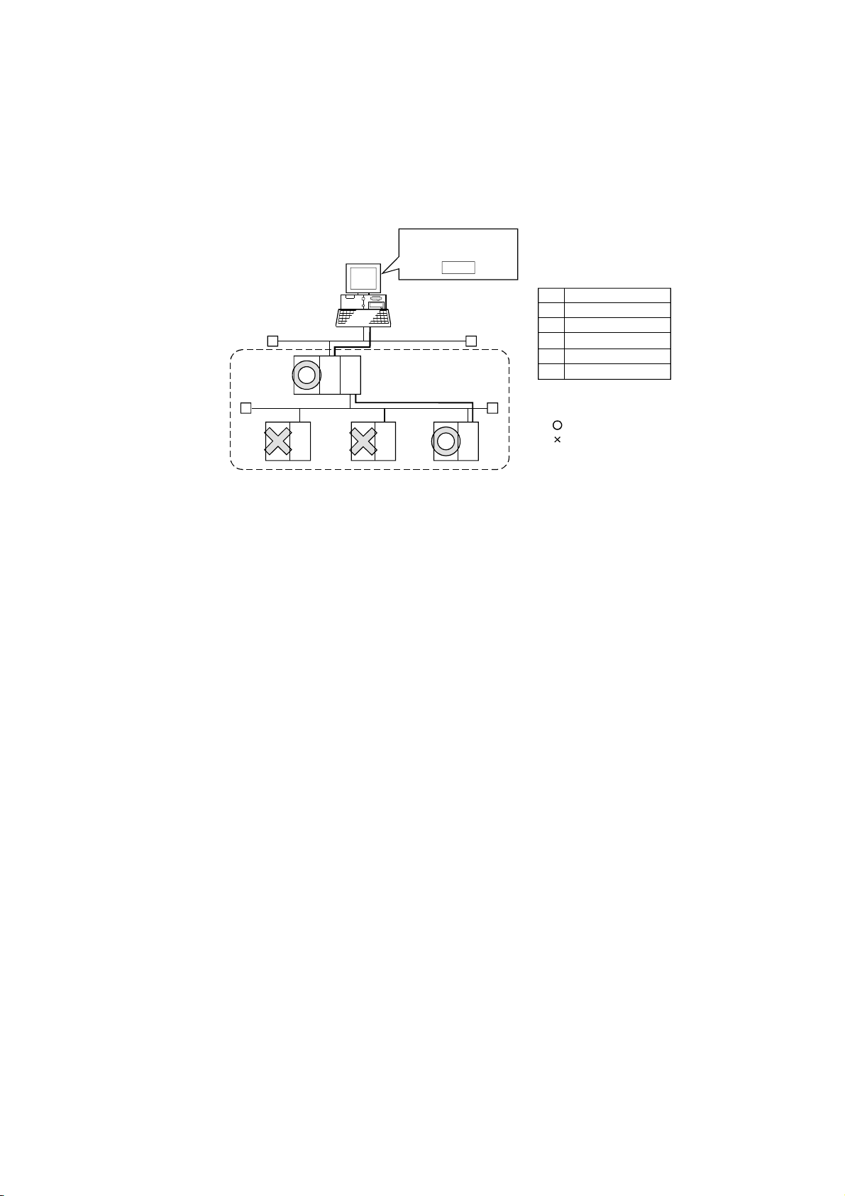
(5) Unlocking password when using QJ71E71
The range where the password can be unlocked by remote operation is up to the
connection target station.
If the password is set also on the lower layer, communication cannot be made
with the programmable controller CPU on the lower layer.
Enter password to
unlock.
AAAA
Ethernet
Remote Password
No.
1)
With setting (AAAA)
2)
Without setting
3)
With setting (AAAA)
4)
With setting (BBBB)
5)
Without setting
QCPU
(Q
mode)
1)
QJ71
E71
Starting
source
2)
QJ71
E71
QCPU
(Q
mode)
Ethernet
4)
3)
QJ71
E71
QCPU
QJ71
(Q
E71
mode)
1) Unlocking QJ71E71 password enables
access to Programmable controller CPUs in this range.
QCPU
(Q
mode)
5)
QJ71
E71
: Accessible
: Inaccessible
(6) About use of the Q4ARCPU
When using the UDP/IP protocol of Ethernet communication, use the Q4ARCPU
whose year and month of manufacture is "0012" or later and whose function
version is B or later.
(7) About Ethernet communication
(a) When access is made to the QnACPU, AnUCPU, QCPU (A mode) or motion
controller CPU via the E71, the device range is equivalent to that of the
AnACPU.
(b) When making access to the programmable controller CPU through Ethernet
communication, the functions may not be executed depending on the
programmable controller CPU status.
1) When the protocol is TCP/IP (target module: E71, QE71)
The functions can be executed only when the communication target
programmable controller CPU is in the RUN mode.
An error is returned if the programmable controller CPU is in other than
the RUN mode.
2) When the protocol is UDP/IP (target module: E71, QE71)
The functions cannot be executed until the communication target
programmable controller CPU is RUN once.
An error is returned if the programmable controller CPU has not been
RUN once.
(c) The communication line is broken if the CPU becomes faulty or the Ethernet
module is reset during Ethernet communication (when the protocol is TCP/IP).
In that case, perform line close processing (Close) and then execute reopen
processing (Open).
A - 12 A - 12
Page 15
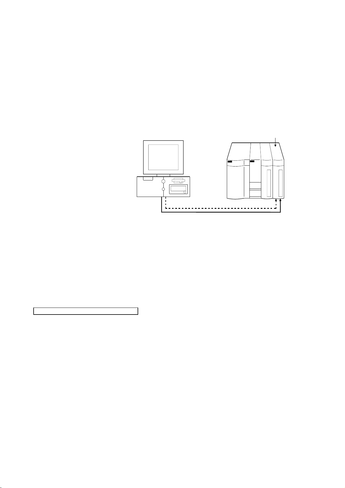
(d) When two different communication systems (protocols) are used to make
access from one IBM-PC/AT compatible to one Q series-compatible E71, two
station numbers, i.e. for TCP/IP and for UDP/IP, must be set. However, it is
not required to set different station numbers for TCP/IP and UDP/IP when
using MX Component Version 3 or later and Q series-compatible E71 with
serial No. 05051 or later.
(Example) When MX Component uses TCP/IP and GX Developer uses
UDP/IP
IBM-PC/AT compatible
(TCP/IP) station number for MX Component: 2
(UDP/IP) station number for GX Developer : 3
GX Developer(UDP/IP)
MX Component(TCP/IP)
Set different station numbers as the (TCP/IP) station number for MX Component
and (UDP/IP) station number for GX Developer. If they are set to the same station
number, an error will occur on the Ethernet module side.
Q series-compatible E71
(Station number: 1)
(8) About switch settings of E71 and QE71
If the four lower digits of the error code that occurred during Ethernet
communication using the E71 or QE71 is not indicated in the E71 or QE71 manual,
check the DIP switch (SW2) setting of the E71 or QE71.
If the DIP switch is not set correctly, a difference has occurred in the packet format
(ASCII/binary) and therefore the error code returned from the module cannot be
recognized correctly.
Instructions for use of CC-Link modules
(1) Software version of CC-Link master/local module
As the CC-Link master/local module used in CC-Link communication or CC-Link
G4 communication (only when the AJ65BT-G4 is used), use the module of
software version "N" or later.
The module of software version "M" or earlier will not operate properly.
(2) Software version of CC-Link G4 module
As the CC-Link G4 module used in CC-Link G4 communication (only when the
AJ65BT-G4 is used), use the module of software version "D" or later.
The module of software version "C" or earlier will not operate properly.
A - 13 A - 13
Page 16

Instructions for the use of MELSECNET(II), MELSECNET/10 and MELSECNET/H
(1) About relaying from the MELSECNET/10 loaded station
When the module is loaded to the AnNCPU or AnACPU, it is recognized as a
MELSECNET(II) module.
When the connected station is the AnNCPU or AnACPU, set the relayed network
as MELSECNET(II).
In addition, set the station number to "0" when making access to the control
station.
(2) Instructions for relaying the MELSECNET(II)
When access is made to the QnACPU, AnUCPU, QCPU (A mode) or motion
controller CPU via the MELSECNET(II), the device range is equivalent to that of
the AnACPU.
Instructions for use of computer link and serial communication modules
(1) About computer link communication
(a) If the connected station CPU is the AnUCPU and the computer link module is
the UC24 for computer link connection, remote operation will result in an error
when access is made to the AnNCPU, AnACPU or QnACPU via the
MELSECNET/10.
(b) On any computer link modules other than the UC24 and C24, remote
"PAUSE" operation will result in an error for all connections.
(c) For the QC24, note that the illegal case of specifying the first I/O number of a
non-existing module and reading/writing U
software version of the module is "k" or earlier.
(d) In any connection form (direct coupling, relaying) where the target station of
the UC24 or C24 is the QnACPU, an error is returned if clock data read/write
is executed.
(e) The FX extended port is required when performing the computer link
communication using FX
0N, FX1S, FX1N(C), FX3G, FX3U(C)CPU.
(2) Precautions for connecting personal computer and serial communication module
(a) When QJ71C24-R2 of function version A is used
An MX Component application can use only either of CH1 and CH2.
When the MELSOFT product, such as GX Developer or GOT, is using one
channel, the application cannot use the other channel.
When the QJ71C24-R2 of function version B is used, the application can use
both channels.
(b) When AJ71QC24-R2 or A1SJ71QC4-R2 or AJ71QC24N-R2 or
A1SJ71QC24N-R2 is used
The MX Component application can use only CH1.
It cannot use CH2.
\G will not return an error if the
A - 14 A - 14
Page 17

Instructions for modem communication
(1) Simultaneous modem communications
It is not allowed to simultaneously perform modem communications using MX
Component and other application such as GX Developer.
Do not perform a modem communication using other applications during a modem
communication using MX Component.
If modem communications are simultaneously performed using MX Component
and other application, this will result in a communication error, disconnection of
telephone line or similar problem.
(2) Instructions for the use of telephone line
(a) Do not use the call-waiting phone line.
On the call-waiting phone line, data corruption, telephone line disconnection
or similar may occur due to interrupt reading sounds.
(b) Do not connect the line to master/slave phones.
If the handset of the slave phone is lifted while the telephone line is
connecting to the master/slave phones, the telephone line may be
disconnected.
(c) Use an analog 2 wire type telephone line.
When using a digital line, use a terminal adaptor.
When the telephone line is of 4 wire type, the line may not be connected
depending on the wiring type of the modular jack.
For the 4 wire type, conduct connection tests in advance to check for
connection.
(3) Instructions for the use of cellular phone
(a) Modem for radio communication using a cellular phone
Although the modem name is different depending on the maker, the modem
is generically referred to as the cellular phone communication unit in this
manual.
Select the model of the cellular phone communication unit according to the
cellular phone used.
For details, contact the company of your cellular phone.
(b) Cellular phone without auto answer function
For the cellular phone without auto answer function, use a cellular phone
communication unit that has the ANS/ORG/TEL select switch.
If the cellular phone communication unit does not have the ANS/ORG/TEL
select switch, it is impossible to connect the line.
The line connection procedure is different depending on the cellular phone
company and cellular phone model.
For details, contact the maker of your cellular phone.
A - 15 A - 15
Page 18

Instructions for programming
(1) About sample programs, test programs and sample sequence programs
(2) About forced termination of processes during communication
(3) About error at communication start
(4) CheckDeviceString
(5) About ActUMsg control, ActUWzd control, ActMnet2BD control and ActAFBD
(6) Precautions for the use of Act(ML)QJ71E71TCP, Act(ML)AJ71QE71TCP and
(7) Instructions for execution of Disconnect
(a) Sample programs, test programs
The sample programs are attached for your reference to create user
programs.
The test programs are attached to conduct communication tests.
Use these programs on your own responsibility.
(b) Sample sequence programs
The sample sequence programs attached to MX Component must be
modified depending on the system configuration and parameter settings.
Modify them to be best for the system.
Please note that it is user’s responsibility to use the same sequence
programs.
If communication is being made with the same type of control open for multiple
processes, forcing one process to be terminated by Task Manager or the like may
stop the other processes at the communication function execution area.
A communication error may occur within the preset time-out period at a
communication start, e.g. when the communication diagnostic button is pressed,
at a monitor start, or at the execution of any function.
These errors are assumed to be detected before a time-out error.
(Example: Connection cable not connected, at programmable controller power-off)
Do not use the CheckDeviceString method of each ACT control.
control
Installing MX Component registers the ActUMsg control, ActUWzd control,
ActMnet2BD control and ActAFBD control, but do not use them.
Act(ML)AJ71E71TCP controls
(a) Provide an interval longer than the sequence scan time of the Ethernet
module loaded station from when the Open method is executed until the
Close method is executed.
(b) Provide an interval of at least 500ms from when the Close method is
executed until the Open method is executed again.
If execution of Disconnect cannot disconnect the telephone line for some reason,
power off the modem used to make a call to forcibly disconnect the telephone line.
A - 16 A - 16
Page 19

Instructions for use of Microsoft
(1) Precautions for starting multiple Excel files on Windows
Note that Windows
which use many control objects.
* This phenomenon is not attributable to this product.
(a) Conditions on which this phenomenon has been confirmed to occur
(b) Cause
(c) How to judge whether the phenomenon is the same or not
(d) Corrective action
(2) Precautions for the use of EXCEL VBA
Do not set the page feed preview function in the application that uses EXCEL VBA.
Doing so can cause a memory leak or OS basic operation (file operation, printing
or other) fault.
(3) Precautions for the use of Microsoft
(a) If you paste the control to Excel, it may sometimes not be pasted.
(b) Excel allows ACT control resizing, which does not affect the operation of MX
R
Excel
R
R
Me has been confirmed to stop if you run multiple Excel files
Graphic driver : Matrox make MGA Mystique display driver
OS : Windows
R
Me (English version)
Me
Number of controls pasted to Excel files
: A total of 150 or more controls used in the whole BOOK
<Other devices checked by Mitsubishi (reference)>
CPU : Pentium
R
166MHz
Memory : 64MB
Hard disk : 8GB (free space 6GB)
The phenomenon has been confirmed to occur when the Matrox make MGA
Mystique graphic card display driver is used.
This is because Version 4.12 of the MGA Mystique graphic card display driver
is not compatible with Windows
R
Me.
After changing the used graphic driver for the standard VGA driver, delete the
temporary data (*.emf) left in the temporary folder.
After that, try starting multiple Excel files.
The phenomenon seems to be the same if it does not occur by changing the
driver for the standard VGA driver.
If this phenomenon occurs, the temporary data (*.emf) will be left in the
temporary folder of the system.
You have to delete the remaining temporary data (*.emf) manually.
The temporary folder of the system is normally in "C:\Temp".
After that, take either of the following actions.
1) Use the graphic card and display driver which support Windows
R
Me.
2) Reduce the number of control objects pasted to the Excel files.
R
Excel
This phenomenon occurs if the cache file (temporary file) of Excel remains.
In such a case, perform operation in the following procedure.
1) Close Excel.
2) Delete "*.exd" in the Excel 8.0 folder of the temp folders. *1, *2
3) Restart Excel.
*1: The temp folder is located depending on the OS.
*2: When the corresponding folder and file are not displayed, Make the
settings in folder option setting. So that all files and folders will be
displayed.
Component.
To restore the size, set the Height and Width properties of ACT control to "24"
again.
A - 17 A - 17
Page 20
Instructions for use of Microsoft
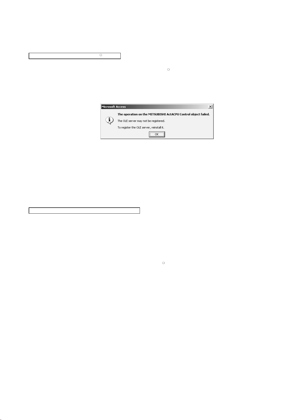
(1) Precautions for the use of Microsoft
(a) When you paste the ACT control to an Access form and double-click the ACT
(b) When you paste the ACT control and display the properties, the property
(c) Access allows ACT control resizing, which does not affect the operation of
R
Access
R
Access
control or select the custom control in the property, the following error
message will appear but this does not affect the operation of ACT control.
(Other error message may appear.)
names displayed may be broken.
As this phenomenon occurs for only the property indication, there will be no
problem in the property functions.
MX Component.
To restore the size, set the Height and Width properties of ACT control to "24"
again.
Instructions for use of VBScript and ASP function
(1) Security of the Internet/intranet when using VBScript
MX Component does not have the Internet/intranet security function.
When you need the security function, make setting on the user side.
(2) Precautions for making CPU COM communication, computer link communication,
CC-Link G4 communication or Ethernet (TCP/IP) communication on ASP page
and application*1 when Windows
If the ASP page opens CPU COM, computer link, CC-Link G4 or Ethernet
(TCP/IP) communication earlier than the application, communication in the same
path cannot be made on the application until the ASP page is closed. Therefore,
note the following points.
(a) CPU COM, computer link, CC-Link G4 or Ethernet (TCP/IP) communication
should be opened on the application earlier.
After it has been opened on the application, communication can be made on
both the application and ASP page until it is closed.
(b) When CPU COM, computer link, CC-Link G4 or Ethernet (TCP/IP)
communication has been opened on the ASP page, always close the
communication.
*1: The application indicates any of the user applications created using the MX
series and MELSOFT products.
R
2000 Professional is used.
A - 18 A - 18
Page 21

INTRODUCTION
Thank you for choosing the Mitsubishi MELSOFT series Integrated FA software.
Read this manual and make sure you understand the functions and performance of MELSOFT series
thoroughly in advance to ensure correct use.
CONTENTS
SAFETY PRECAUTIONS................................................................................................................................A- 1
CONDITIONS OF USE FOR THE PRODUCT ...............................................................................................A- 2
REVISIONS ......................................................................................................................................................A- 3
OPERATING INSTRUCTIONS .......................................................................................................................A- 7
INTRODUCTION..............................................................................................................................................A-19
CONTENTS......................................................................................................................................................A-19
MANUALS ........................................................................................................................................................A-24
HOW TO USE THIS MANUAL ........................................................................................................................A-25
GENERIC TERMS AND ABBREVIATIONS ...................................................................................................A-26
MEANINGS AND DEFINITIONS OF TERMS.................................................................................................A-30
1 OVERVIEW 1- 1 to 1- 6
1.1 Features ..................................................................................................................................................... 1- 1
2 SYSTEM CONFIGURATIONS 2- 1 to 2-32
2.1 System Configuration List.......................................................................................................................... 2- 1
R
2.1.1 When using W indows NT
2.1.2 When using W indows
2.1.3 When using W indows
2.1.4 When using W indows
2.1.5 When using W indows
2.1.6 When using W indows
2.1.7 When using W indows
2.1.8 When using W indows Vista
2.1.9 When using W indows Windows
Workstation Operating System Version 4.0........................................... 2- 1
R
95 Operating System.................................................................................... 2- 2
R
98 Operating System.................................................................................... 2- 3
R
2000 Professional Operating System .......................................................... 2- 4
R
Millennium Edition Operating System .......................................................... 2- 5
R
XP Professional Operating System.............................................................. 2- 6
R
XP Home Edition Operating System............................................................ 2- 7
R
Operating System................................................................................ 2- 8
R
7 Operating System...................................................................... 2- 9
2.2 System Configuration for the Use of Each Connection Form ................................................................2- 10
2.2.1 System configurations .......................................................................................................................2- 10
2.2.2 Details of the communication forms ................................................................................................... 2-12
2.3 Operating Environment .............................................................................................................................. 2-29
2.4 Usable Programmable Controller CPUs ...................................................................................................2-32
3 OPERATION PROCEDURES 3- 1 to 3- 6
3.1 Selecting the Development Type .............................................................................................................. 3- 1
3.2 User Application Creating Procedures ...................................................................................................... 3- 2
R
3.2.1 When using Visual Basic
3.2.2 When using Visual C++
6.0/Visual BasicR.NET............................................................................ 3- 2
R
6.0/Visual C++R.NET ................................................................................ 3- 3
3.2.3 When using VBA ................................................................................................................................. 3- 4
3.2.4 When using VBScript ..........................................................................................................................3- 5
A - 19 A - 19
Page 22

3.3 PLC Monitor Utility Operating Procedure .................................................................................................. 3- 6
4 OPERATIONS COMMON TO UTILITIES 4- 1 to 4- 3
4.1 Starting the Utility .......................................................................................................................................4- 1
4.2 Exiting the Utility ......................................................................................................................................... 4- 3
4.3 Confirming the Version .............................................................................................................................. 4- 3
5 UTILITY OPERATIONS 5- 1 to 5-32
5.1 Communication Setup Utility...................................................................................................................... 5- 1
5.1.1 Operations on target setting screen ...................................................................................................5- 2
5.1.2 Operations on list view screen ............................................................................................................5- 3
5.1.3 Operations on connection test screen ................................................................................................ 5- 4
5.1.4 Operations on com setup import screen ............................................................................................5- 5
5.1.5 Operations on com setup export screen ............................................................................................5- 6
5.1.6 Operations on communication setting wizard screens ......................................................................5- 7
5.1.7 Operations on line setting screen ....................................................................................................... 5-12
5.2 PLC Monitor Utility .....................................................................................................................................5-20
5.2.1 Operations on transfer setting screen ................................................................................................5-20
5.2.2 Operations on device batch screen .................................................................................................... 5-23
5.2.3 Operations on buffer memory screen................................................................................................. 5-25
5.2.4 Operation on entry device screen....................................................................................................... 5-27
5.2.5 Operations on device write screen ..................................................................................................... 5-29
5.2.6 Operations on clock setting screen .................................................................................................... 5-30
5.2.7 Operations on telephone line connection, disconnection screens ....................................................5-31
6 COMMUNICATION SETTING EXAMPLES OF THE UTILITY SETTING TYPE 6- 1 to 6-128
6.1 Computer Link Communication ................................................................................................................. 6- 1
6.1.1 Settings of computer link modules...................................................................................................... 6- 1
6.1.2 Accessing procedure........................................................................................................................... 6- 9
6.2 Ethernet Communication (In case of using Ethernet interface modules)................................................. 6-15
6.2.1 Switch settings of Ethernet modules .................................................................................................. 6-15
6.2.2 Accessing procedure........................................................................................................................... 6-16
6.3 Ethernet Communication (In case of using Built-in Ethernet port CPUs) ................................................6-30
6.3.1 Accessing procedure........................................................................................................................... 6-30
6.4 Ethernet Communication (In case of using CC-Link IE Field Network Ethernet adapter module) ......... 6-35
6.4.1 Accessing procedure........................................................................................................................... 6-35
6.5 CPU COM Communication........................................................................................................................6-39
6.5.1 Accessing procedure........................................................................................................................... 6-39
6.6 CPU USB Communication......................................................................................................................... 6-43
6.6.1 Accessing procedure........................................................................................................................... 6-43
6.7 MELSECNET/10 Communication .............................................................................................................6-47
6.7.1 Accessing procedure........................................................................................................................... 6-47
6.8 CC-Link Communication ............................................................................................................................ 6-52
6.8.1 Accessing procedure........................................................................................................................... 6-52
A - 20 A - 20
Page 23

6.9 CC-Link G4 Communication ...................................................................................................................... 6-57
6.9.1 Switch settings of CC-Link G4 module ............................................................................................... 6-57
6.9.2 Accessing procedure........................................................................................................................... 6-59
6.10 CPU Board Communication ....................................................................................................................6-66
6.10.1 Accessing procedure......................................................................................................................... 6-66
6.11 GX Simulator Communication ................................................................................................................. 6-72
6.11.1 Accessing procedure......................................................................................................................... 6-72
6.12 GX Simulator2 Communication ............................................................................................................... 6-75
6.12.1 Accessing procedure......................................................................................................................... 6-75
6.13 MELSECNET/H Communication............................................................................................................. 6-78
6.13.1 Accessing procedure......................................................................................................................... 6-78
6.14 CC-Link IE Controller Network Communication...................................................................................... 6-83
6.14.1 Accessing procedure......................................................................................................................... 6-83
6.15 CC-Link IE Field Network Communication.............................................................................................. 6-88
6.15.1 Accessing procedure......................................................................................................................... 6-88
6.16 Q Series Bus Communication .................................................................................................................6-94
6.16.1 Accessing procedure......................................................................................................................... 6-94
6.17 Modem Communication........................................................................................................................... 6-98
6.17.1 Switch settings of A6TEL, Q6TEL, QC24N, Q Series Corresponding C24,
L Series Corresponding C24............................................................................................................ 6-98
6.17.2 Access procedure ...........................................................................................................................6-100
6.18 Gateway Function Communication .......................................................................................................6-120
6.18.1 Access procedure ...........................................................................................................................6-120
6.19 GOT Transparent Communication ........................................................................................................ 6-125
6.19.1 Access procedure ...........................................................................................................................6-125
7 COMMUNICATION SETTING EXAMPLES OF THE PROGRAM SETTING TYPE 7- 1 to 7- 2
8 ACCESSIBLE DEVICES AND RANGES 8- 1 to 8-77
8.1 Precautions for Device Access.................................................................................................................. 8- 1
8.2 For Computer Link Communication........................................................................................................... 8- 2
8.2.1 Accessible devices .............................................................................................................................. 8- 2
8.2.2 Accessible ranges ...............................................................................................................................8- 4
8.3 For Ethernet Communication..................................................................................................................... 8- 6
8.3.1 Accessible devices .............................................................................................................................. 8- 6
8.3.2 Accessible ranges (For the use of Ethernet interface modules)........................................................ 8- 8
8.3.3 Accessible ranges (For the use of Built-in Ethernet port CPUs) ....................................................... 8-10
8.3.4 Accessible ranges (For the use of CC-Link IE Field Network Ethernet adapter module) ................ 8-12
8.4 For CPU COM Communication ................................................................................................................. 8-14
8.4.1 Accessible devices .............................................................................................................................. 8-14
8.4.2 Accessible ranges ...............................................................................................................................8-16
8.5 For CPU USB Communication ..................................................................................................................8-18
8.5.1 Accessible devices .............................................................................................................................. 8-18
8.5.2 Accessible ranges ...............................................................................................................................8-20
A - 21 A - 21
Page 24

8.6 For MELSECNET/10 Communication....................................................................................................... 8-22
8.6.1 Accessible devices .............................................................................................................................. 8-22
8.6.2 Accessible ranges ...............................................................................................................................8-24
8.7 For CC-Link Communication .....................................................................................................................8-26
8.7.1 Accessible devices .............................................................................................................................. 8-26
8.7.2 Accessible ranges ...............................................................................................................................8-29
8.8 For CC-Link G4 Communication ...............................................................................................................8-30
8.8.1 Accessible devices .............................................................................................................................. 8-30
8.8.2 Accessible ranges ...............................................................................................................................8-32
8.9 For CPU Board Communication................................................................................................................ 8-34
8.9.1 Accessible devices .............................................................................................................................. 8-34
8.9.2 Accessible ranges ...............................................................................................................................8-36
8.10 For MELSECNET/H Communication ...................................................................................................... 8-37
8.10.1 Accessible devices............................................................................................................................ 8-37
8.10.2 Accessible ranges ............................................................................................................................. 8-39
8.11 For CC-Link IE Controller Network Communication ............................................................................... 8-41
8.11.1 Accessible devices............................................................................................................................ 8-41
8.11.2 Accessible ranges ............................................................................................................................. 8-43
8.12 For CC-Link IE Field Network Communication .......................................................................................8-44
8.12.1 Accessible devices............................................................................................................................ 8-44
8.12.2 Accessible ranges ............................................................................................................................. 8-46
8.13 For Q Series Bus Communication........................................................................................................... 8-47
8.13.1 Accessible devices............................................................................................................................ 8-47
8.13.2 Accessible ranges ............................................................................................................................. 8-48
8.14 For Modem Communication .................................................................................................................... 8-49
8.14.1 Accessible devices............................................................................................................................ 8-49
8.14.2 Accessible ranges ............................................................................................................................. 8-51
8.15 For Gateway Function Communication................................................................................................... 8-54
8.15.1 Accessible devices............................................................................................................................ 8-54
8.15.2 Accessible ranges ............................................................................................................................. 8-54
8.16 For GX Simulator Communication........................................................................................................... 8-55
8.16.1 Accessible devices............................................................................................................................ 8-55
8.16.2 Accessible ranges ............................................................................................................................. 8-55
8.17 For GX Simulator2 Communication ........................................................................................................ 8-56
8.17.1 Accessible devices............................................................................................................................ 8-56
8.17.2 Accessible ranges ............................................................................................................................. 8-56
8.18 For GOT Transparent Communication ................................................................................................... 8-57
8.18.1 Accessible devices............................................................................................................................ 8-57
8.18.2 Accessible ranges ............................................................................................................................. 8-59
A - 22 A - 22
Page 25

APPENDICES APP- 1 to APP-62
Appendix 1 Concept of the Routing Parameters........................................................................................APP- 1
Appendix 2 How to Start the Internet/Intranet Environment ......................................................................APP- 4
Appendix 2.1 Operating procedure.........................................................................................................APP- 4
Appendix 2.2 Conditions of usable personal computers........................................................................APP- 5
Appendix 2.3 How to install Web server .................................................................................................APP- 6
Appendix 2.4 Setting the Internet access account .................................................................................APP- 7
Appendix 2.5 Making Web pages public ................................................................................................APP-15
Appendix 2.6 Checking whether access can be made to Web server properly or not .........................APP-19
Appendix 3 RS-232 Cable wiring example when performing computer link communication ...................APP-20
Appendix 3.1 A Series.............................................................................................................................APP-20
Appendix 3.2 QnA Series........................................................................................................................APP-22
Appendix 3.3 Q Series ............................................................................................................................APP-24
Appendix 3.4 FX Series...........................................................................................................................APP-25
Appendix 4 Multi-CPU System ...................................................................................................................APP-26
Appendix 5 Number of Loadable Network Modules When Q00JCPU, Q00UJCPU,Q00CPU, Q00UCPU,
Q01CPU or Q01UCPU Is Used ..............................................................................................APP-27
Appendix 6 Flowchart for the case where access cannot be performed during modem communication
.................................................................................................................................................APP-28
Appendix 7 Compatibility with Redundant CPU.........................................................................................APP-29
R
Appendix 8 Warning Message Appears on Windows Vista
and WindowsR7 ........................................APP-36
Appendix 8.1 Overview of the warning message ...................................................................................APP-36
Appendix 8.2 Methods for preventing the warning message.................................................................APP-37
Appendix 9 Restrictions by DEP function...................................................................................................APP-43
Appendix 9.1 Data Execution Prevention (DEP)....................................................................................APP-43
Appendix 9.2 Symptoms .........................................................................................................................APP-43
Appendix 9.3 DEP Configurations that May Cause Problems ..............................................................APP-44
Appendix 9.4 Configurations for Avoiding Problems due to the Effect of DEP.....................................APP-45
Appendix 9.5 Workarounds for Problems...............................................................................................APP-53
Appendix 9.6 Distinguishing Types of Projects ......................................................................................APP-62
A - 23 A - 23
Page 26

MANUALS
The following lists the manuals for this software package.
Refer to the following table when ordering manuals.
Related Manuals
Manual Name
MX Component Version 3 Operating Manual (Startup)
Explains procedures for installing and uninstalling MX Component and for browsing the operating manual.
(Sold separately)
MX Component Version 3 Programming Manual
Explains the programming procedures, detailed explanations and error codes of the ACT controls.
(Sold separately)
Manual Number
(Model Code)
SH-080270
(13JU31)
SH-080272
(13JF66)
Type A70BDE-J71QLP23/A70BDE-J71QLP23GE/A70BDE-J71QBR13/A70BDE-J71QLR23
MELSECNET/10 Interface Board User's Manual (For SW3DNF-MNET10)
Explains the features, specifications, part names and setting of the MELSECNET/10 board, and the
installation, uninstallation and others of the driver. (Sold separately)
IB-0800035
(13JL93)
Type A80BDE-J61BT11 Control & Communication Link System Master/Local Interface Board
User's Manual (For SW4DNF-CCLINK-B)
Explains the features, specifications, part names and setting of the CC-Link master board, and the installation,
uninstallation and others of the driver. (Sold separately)
IB-0800175
(13JR28)
Type A80BDE-J61BT13 Control & Communication Link System Local Interface Board
User's Manual (For SW4DNF-CCLINK-B)
Explains the features, specifications, part names and setting of the CC-Link local board, and the installation,
uninstallation and others of the driver. (Sold separately)
IB-0800176
(13JR29)
Type Q80BD-J61BT11N/Q81BD-J61BT11 CC-Link System Master/ Local Interface Board User's
Manual (For SW1DNC-CCBD2-B)
Explains the system configuration, software package installation, uninstallation and each utility's operation
method, accessible range, devices and troubleshooting. (Sold separately)
SH-080527ENG
(13JR77)
Type A80BDE-A2USH-S1 programmable controller CPU Board User's Manual
(For SW1DNF-ANU-B)
Explains the features, specifications, part names and setting of the CPU board, and the installation,
uninstallation and others of the driver. (Sold separately)
MELSECNET/H Interface Board User's Manual (For SW0DNC-MNETH-B)
Explains the features, specifications, part names and setting of the MELSECNET/H board, and the installation,
uninstallation and others of the driver. (Sold separately)
IB-0800174
(13JR27)
SH-080128
(13JR24)
CC-Link IE Controller Network Interface Board User’s Manual (For SW1DNC-MNETG-B)
Explains system configuration, installation/uninstallation of the software package, operating methods of each
utility, accessible range, devices, and troubleshooting of the CC-Link IE Controller Network board.
(Sold separately)
GX Simulator Version 7 Operating Manual
Explains the setting and operating method for monitoring the device memory and simulating the machine side
operations using GX Simulator. (Sold separately)
GX Works2 Version 1 Operating Manual (Common)
Explains the system configuration of GX Works2 and the functions common to a Simple project and Structured
project such as parameter setting, operation method for the online function. (Sold separately)
SH-080691ENG
SH-080468ENG
SH-080779ENG
(13JZ02)
(13JU51)
(13JU63)
Note: The MX Component Version 3 Operating Manual (Startup) and MX Component Version 3 Programming
Manual are stored on the CD-ROM of the corresponding software package in PDF format.
When you want to purchase the manual alone, it is optionally available as the printed matter of the
manual number (Model code) in the above table.
A - 24 A - 24
Page 27

HOW TO USE THIS MANUAL
"HOW TO USE THIS MANUAL" is given purpose-by-purpose for the use of MX
Component.
Refer to the following outlines and use this manual.
(1) To know the features (Section 1.1)
Section 1.1 gives the features.
(2) To know the system configurations (Sections 2.1, 2.2)
The system configurations using MX Component are provided.
(3) To know the MX Component operating environment and usable programmable
controller CPUs (Sections 2.3, 2.4)
Section 2.3 gives the operating environment of MX Component and Section 2.4
indicates usable programmable controller CPUs.
(4) To know the MX Component operating procedures (Chapter 3)
Chapter 3 provides the operation procedures of MX Component.
(5) To know how to operate the utilities (Chapters 4, 5)
Chapter 4 describes operations common to the utilities, and Chapter 5 explains
how to operate the utilities.
Read these chapters when using the utilities.
(6) To know the communication setting examples of the utility setting type
(Chapter 6)
Chapter 6 gives the setting example of each communication path using the utility
setting type.
(7) To know the communication setting examples of the program setting type
(Chapter 7)
Chapter 7 provides the setting example of each communication path using the
program setting type.
(8) To know the accessible devices and ranges (Chapter 8)
Chapter 8 contains the accessible devices and accessible ranges.
A - 25 A - 25
Page 28

GENERIC TERMS AND ABBREVIATIONS
Unless otherwise started, this manual uses the following abbreviations and terms for
the explanation of MX Component.
Generic Term/Abbreviation Description
MX Component
IBM-PC/AT compatible Abbreviation for IBM PC/AT or its compatible personal computer
PC CPU module
GX Developer
GX Works2 Generic product name for SWnDNC-GXW2 (n: version)
GX Simulator
MELSECNET/10 board
MELSECNET/H board
CC-Link IE Controller Network
board
CC-Link IE Field Network
board
CC-Link board
CPU board Abbreviation for Type A80BDE-A2USH-S1 programmable controller CPU board
AnNCPU
AnACPU
AnUCPU
QnACPU
ACPU Generic term for AnNCPU, AnACPU and AnUCPU
QCPU (A mode) Generic term for Q02CPU-A, Q02HCPU-A and Q06HCPU-A
QCPU (Q mode)
Built-in Ethernet port QCPU
LCPU Generic term for L02CPU, L26CPU-BT
Built-in Ethernet port CPU Generic term for built-in Ethernet port QCPU and LCPU
Generic product name for SWnD5C-ACT-E and SWnD5C-ACT-EA (n: version)
-EA means a volume-license product.
Abbreviation for MELSEC-Q series compatible PC CPU module
(CONTEC CO., LTD. make)
Generic product name for SWnD5C-GPPW-E, SWnD5C-GPPW-EA,
SWnD5C-GPPW-EV, and SWnD5C-GPPW-EVA (n: version)
-EA means a volume-license product, and -EV an updated product.
Generic product name for SWnD5C-LLT-E, SWnD5C-LLT-EA, SWnD5C-LLT-EV, and
SWnD5C-LLT-EVA (n: version)
-EA means a volume-license product, and -EV an updated product.
Abbreviation for Type A70BDE-J71QLP23/A70BDE-J71QLP23GE/A70BDE-J71QBR13/
A70BDE-J71QLR23 MELSECNET/10 interface board
Abbreviation for Type Q80BD-J71LP21-25/Q81BD-J71LP21-25/
Q80BD-J71LP21S-25/Q80BD-J71LP21G/Q80BD-J71BR11 MELSECNET/H board
Abbreviation for Type Q80BD-J71GP21-SX/Q80BD-J71GP21S-SX CC-Link IE
Controller Network interface board
Abbreviation for Type Q81BD-J71GF11-T2 CC-Link IE Field Network interface board
Generic term for Type A80BDE-J61BT11 CC-Link system master/local interface board,
Type A80BDE-J61BT13 CC-Link interface board, and Type Q80BD-J61BT11N/
Q81BD-J61BT11 CC-Link system master/local interface board
Generic term for A0J2HCPU, A1SCPU, A1SCPU-S1, A1SCPUC24-R2, A1SHCPU,
A1SJCPU, A1SJHCPU, A1NCPU, A2CCPU, A2CCPUC24, A2CCPUC24-PRF,
A2CJCPU, A2NCPU, A2NCPU-S1, A2SCPU, A2SCPU-S1, A2SHCPU, A2SHCPU-S1,
A3NCPU and A1FXCPU
Generic term for A2ACPU, A2ACPU-S1, A2ACPUP21/R21, A2ACPUP21-S1, A3ACPU
and A3ACPUP21/R21
Generic term for A2UCPU, A2UCPU-S1, A2USCPU, A2USCPU-S1, A2ASCPU,
A2ASCPU-S1, A2ASCPU-S30, A2USHCPU-S1, A3UCPU and A4UCPU
Generic term for Q2ACPU, Q2ACPU-S1, Q2ASCPU, Q2ASCPU-S1, Q2ASHCPU,
Q2ASHCPU-S1, Q3ACPU, Q4ACPU and Q4ARCPU
Generic term for Q00JCPU, Q00UJCPU, Q00CPU, Q00UCPU, Q01CPU, Q01UCPU,
Q02CPU, Q02HCPU, Q02PHCPU, Q02UCPU, Q03UDCPU, Q03UDECPU,
Q04UDHCPU, Q04UDEHCPU, Q06HCPU, Q06PHCPU, Q06UDHCPU,
Q06UDEHCPU, Q10UDHCPU, Q10UDEHCPU, Q12HCPU, Q12PHCPU,
Q12PRHCPU, Q13UDHCPU, Q13UDEHCPU, Q20UDHCPU, Q20UDEHCPU,
Q25HCPU, Q25PHCPU, Q25PRHCPU, Q26UDHCPU, Q26UDEHCPU,
Q50UDEHCPU and Q100UDEHCPU
Generic term for Q03UDECPU, Q04UDEHCPU, Q06UDEHCPU, Q10UDHCPU,
Q10UDEHCPU, Q13UDEHCPU, Q26UDEHCPU, Q50UDEHCPU and Q100UDEHCPU
A - 26 A - 26
Page 29

Generic Term/Abbreviation Description
QSCPU Abbreviation for a safety CPU module (QS001CPU)
Generic term for FX
FXCPU
Motion controller CPU
FX
1SCPU, FXUCPU, FX2CCPU, FX2NCPU, FX2NCCPU, FX3GCPU, FX3UCPU and
FX
3UCCPU
Generic term for A171SHCPU, A172SHCPU, A173UHCPU, A173UHCPU-S1,
A273UHCPU and A273UHCPU-S3
C Controller CPU Abbreviation for Q12DCCPU-V
Programmable controller CPU
C24
UC24
QC24
QC24N
Generic term for QCPU(Q mode), LCPU, QSCPU, QCPU(A mode), QnACPU, ACPU,
FXCPU, motion controller CPU and C Controller CPU
Generic term for A1SCPUC24-R2, A1SJ71C24-PRF, A1SJ71C24-R2,
A1SJ71C24-R4, A2CCPUC24, A2CCPUC24-PRF, AJ71C24-S6 and AJ71C24-S8
Generic term for AJ71UC24, A1SJ71UC24-R2, A1SJ71UC24-R4 and
A1SJ71UC24-PRF
Generic term for AJ71QC24, AJ71QC24-R2, AJ71QC24-R4, A1SJ71QC24-R2 and
A1SJ71QC24-R2
Generic term for AJ71QC24N, AJ71QC24N-R2, AJ71QC24N-R4, A1SJ71QC24N
and A1SJ71QC24N-R2
QC24(N) Generic term for QC24 and QC24N
Q series-compatible C24
Generic term for QJ71C24, QJ71C24-R2, QJ71C24N, QJ71C24N-R2 and
QJ71C24N-R4
L series-compatible C24 Generic term for LJ71C24, LJ71C24-R2
FX extended port
Generic term for FX
FX3G-485-BD, FX3U-485-BD and FX3U-485ADP
Generic term for C24, UC24, QC24(N), Q series-compatible C24,
Computer link module
(Serial communication module)
L series-compatible C24 and FX extended port
Described as the serial communication module especially to indicate QC24(N) or
Q series-compatible C24, L series-compatible C24.
Generic term for AJ71E71, AJ71E71-S3, A1SJ71E71-B2, A1SJ71E71-B5,
E71
A1SJ71E71-B2-S3, A1SJ71E71-B5-S3, AJ71E71N-T, AJ71E71N-B5, AJ71E71NB2, AJ71E71N-B5T, AJ71E71N3-T, A1SJ71E71N-T, A1SJ71E71N-B5,
A1SJ71E71N-B2, A1SJ71E71N-B5T and A1SJ71E71N3-T
Generic term for AJ71QE71, AJ71QE71-B5, A1SJ71QE71-B2, A1SJ71QE71-B5,
QE71
AJ71QE71N-T, AJ71QE71N-B5, AJ71QE71N-B2, AJ71QE71N-B5T, AJ71QE71N3T, A1SJ71QE71N-T, A1SJ71QE71N-B5, A1SJ71QE71N-B2, A1SJ71QE71N-B5T
and A1SJ71QE71N3-T
Q series-compatible E71 Generic term for QJ71E71, QJ71E71-B2, QJ71E71-B5 and QJ71E71-100
Ethernet module Generic term for E71, QE71 and Q series-compatible E71
CC-Link G4 module
CC-Link IE Field Network
Ethernet adapter module
Generic term for AJ65BT-G4 GPP function peripheral connection module and
AJ65BT-G4-S3 GPP function peripheral connection module
Abbreviation for NZ2GF-ETB CC-Link IE Field Network Ethernet adapter module
A6TEL Abbreviation for A6TEL modem interface module
Q6TEL Abbreviation for Q6TEL modem interface module
GOT Abbreviation for Graphic Operation Terminal
GOT1000 Abbreviation for Graphic Operation Terminal GOT1000 series
0CPU, FX0SCPU, FX0NCPU, FX1CPU, FX1NCPU, FX1NCCPU,
0N-485ADP, FX2NC-485ADP, FX1N-485-BD, FX2N-485-BD,
A - 27 A - 27
Page 30

Generic Term/Abbreviation Description
Abbreviation for communication with programmable controller CPU using the
Computer link communication
(Serial communication)
Ethernet communication
CPU COM communication
CPU USB communication
MELSECNET/10 communication
MELSECNET/H communication
CC-Link IE Controller Network
communication
CC-Link IE Field Network
communication
CC-Link communication
CC-Link G4 communication
CPU board communication
Q series bus communication
GX Simulator communication Abbreviation for communication with GX Simulator
GX Simulator2 communication Abbreviation for communication using the simulation functions of GX Works2
Modem communication
Gateway function communication
GOT transparent communication
Utility setting type Abbreviation for user program creation using the communication settings utility
Program setting type
ACT controls Generic term for ActiveX controls offered by MX Component
Redundant CPU Generic term for Q12PRHCPU and Q25PRHCPU
Redundant type extension base
unit
computer link module
Described as serial communication especially in communication that uses QC24(N)
or Q series-compatible C24, L series-compatible C24.
Abbreviation for communication by connecting the IBM-PC/AT compatible to
Ethernet module or the built-in Ethernet port CPU
Abbreviation of communication made by connecting the IBM-PC/AT compatible to
the RS-232 or RS-422 connector of programmable controller CPU
Abbreviation for communication by connecting IBM-PC/AT compatible to the USB
connector of QCPU (Q mode), LCPU
Abbreviation for communication with programmable controller CPU using
MELSECNET/10 board
Abbreviation for communication with programmable controller CPU using
MELSECNET/H board
Abbreviation for communication with programmable controller CPU using CC-Link
IE Controller Network board
Abbreviation for communication with programmable controller CPU using CC-Link
IE Field Network board
Abbreviation for communication with programmable controller CPU using CC-Link
board
Abbreviation for communication with programmable controller CPU using CC-Link
G4 module
Abbreviation for communication with programmable controller CPU using CPU
board
Abbreviation for communication with programmable controller CPU on the same
base using PC CPU module
Abbreviation for communication with programmable controller CPU via modems
using QC24N (except AJ71QC24N-R4), Q series-compatible C24, L seriescompatible C24, A6TEL, Q6TEL or FXCPU
Abbreviation for communication with programmable controller CPU and third-party
programmable controllers using the gateway functions of GOT
Abbreviation for communication with programmable controller CPU using the GOT
transparent functions of GOT
Abbreviation for user program creation without using the communication settings
utility
Abbreviation for Q65WRB extension base unit for redundant system
A - 28 A - 28
Page 31

Generic Term/Abbreviation Description
Generic term for Microsoft
MicrosoftRWindowsR7 Home Premium Operating System,
MicrosoftRWindowsR7 Professional Operating System,
WindowsR7
Microsoft
R
WindowsR7 Ultimate Operating System and
MicrosoftRWindowsR7 Enterprise Operating System
Note that the 32-bit version is designated as "32-bit Windows
version is designated as "64-bit Windows
Generic term for Microsoft
MicrosoftRWindows VistaRHome Premium Operating System,
Windows VistaR
MicrosoftRWindows VistaRBusiness Operating System,
Microsoft
R
Windows VistaRUltimate Operating System and
MicrosoftRWindows VistaREnterprise Operating System
WindowsRXP
Visual BasicR.NET
Generic term for Microsoft
Microsoft
Generic term for Visual Basic version Visual Studio
Visual Studio
R
WindowsRXP Home Edition Operating System
R
2005, Visual StudioR2008, and Visual StudioR2010
Visual C++R.NET Abbreviation for creation of an application using .NET Framework
R
WindowsR7 Starter Operating System,
R
R
R
Windows VistaRHome Basic Operating System,
R
WindowsRXP Professional Operating System and
7".
R
.NET 2003,
7", and the 64-bit
A - 29 A - 29
Page 32

MEANINGS AND DEFINITIONS OF TERMS
The terms used in this manual have the following meanings and definitions.
(1) Logical station number
The connection target information necessary to open the communication line is
combined into one data using the communication setup utility, and that data is
provided with a logical number.
This number may be used with the utility setting type only.
(Example) For CPU COM communication
IBM-PC/AT compatible
CPU COM
communication (COM 1)
Time-out period
(2) Utility setting type
The communication setup utility (logical station number) is used to create a user
program.
In the user program, the communication line can be connected easily by simply
specifying the logical station number set on the communication setting wizard.
Use ActEasyIF and ActMLEasyIF.
(3) Program setting type
A user program is created without using the communication setup utility.
Make ACT control settings for the corresponding communication in the user
program or on the property page or like of Visual Basic
The properties necessary to be set depend on the ACT control.
Use the control other than ActEasyIF and ActMLEasyIF.
(CPU to communicate with)
Q25HCPU
MELSECNET/H
(Network No. 1)
Transmission speed
Transmission control
Target information up to CPU to communicate with is combined
into one data, to which logical station number is assigned.
QJ71LP21
(Station number: 1)
R
or Visual C++R.
Q25HCPU
QJ71LP21
(Station number: 3)
A - 30 A - 30
Page 33

1 OVERVIEW
MELSOFT
1 OVERVIEW
1.1 Features
MX Component is a tool designed to implement communication from an IBM-PC/AT
compatible personal computer to the programmable controller without any knowledge
of communication protocols and modules.
Use of common functions has made it extremely easy to develop serial communication
and Ethernet communication programs which had been troublesome and complex.
When applying any of the following program examples to the actual system, make sure
to examine the applicability and confirm that no problem will occur in the system
control.
MX Component has the following features.
(1) Support of a wide range of communication paths for programmable
controller
A wide range of communication paths to the programmable controller are
supported to enable the user to configure up a system as desired.
(2) Substantial improvement in user's development efficiency
MX Component comes with the wizard type communication setup utility.
By simply making interactive settings on the screen, the user can achieve
communication settings to access the programmable controller CPU to
communicate with.
Once the communication settings have been made, access can be made by
merely specifying the logical station number of the programmable controller
stored on the communication setup utility.
(3) Save and read of communication settings
MX Component has the functions to save and read the communication settings
made on the communication setup utility.
You can move the set data easily from the IBM-PC/AT compatible used for
development to the actually used IBM-PC/AT compatible.
Note: MX Component must have been installed in both the IBM-PC/AT
compatible used for development and the actually used IBM-PC/AT
compatible.
IBM-PC/AT compatible
used for development
MX
Component
Communication
setup data are
moved.
Actually used
IBM-PC/AT compatible
MX
Component
1
Enter and save communication
setup data.
Read communication setup data and
establish communication path.
Reduction of on-site working time
1 - 1 1 - 1
Page 34

1 OVERVIEW
1
MELSOFT
(4) Device monitor function
Utilizing the PLC monitor utility enables you to monitor the status of the specified
device and change its data. *1
X39 is ON.
X39 is ON!
MX
Component
*1: Device data of the QSCPU cannot be changed.
Device status is checked.
Set and connect communication
path on MX Component.
(5) Access to buffer memory of special function module
Access can be made to not only the devices of the programmable controller CPU
but also the buffer memory of an intelligent function or special function module.
Buffer memory data of connected intelligent
or special function module can be read/written!*2
MX
Component
Access to buffer memory
*2: Buffer memory data of the QSCPU cannot be written.
(6) Read/write of programmable controller CPU clock data
You can read and write the clock data of the programmable controller CPU
connected to the IBM-PC/AT compatible. *3
Clock data of connected programmable
controller CPU can be read/written!
MX
Component
Access to clock data
*3: Clock data of the QSCPU cannot be written.
1 - 2 1 - 2
Page 35

r
1 OVERVIEW
(7) Multithread communication
Access to the same communication path can be made from multiple threads at
the same time.
User program
MELSOFT
Thread 1
Act control 1
Thread 2
Act control 2
(8) GX Simulator or the simulator function of GX Works2 (GX
Simulator2) for offline debugging *4
By using GX Developer and GX Simulator or the simulation function of GX
Works2, you can perform debugging on a single IBM-PC/AT compatible without
connecting the programmable controller.
You can debug by accessing
GX Simulator or GX Simulator2 on
the same IBM-PC/AT compatible!
MX
Component
IBM-PC/AT compatible Programmable controlle
Programmable controller
CPU need not be connected.
*4: This function is not available with the QSCPU.
POINT
• GX Developer and GX Simulator are separately required to use the GX Simulator.
• GX Works2 is separately required to use GX Simulator2.
• The maximum of 4 projects can be simulated simultaneously.
1 - 3 1 - 3
Page 36
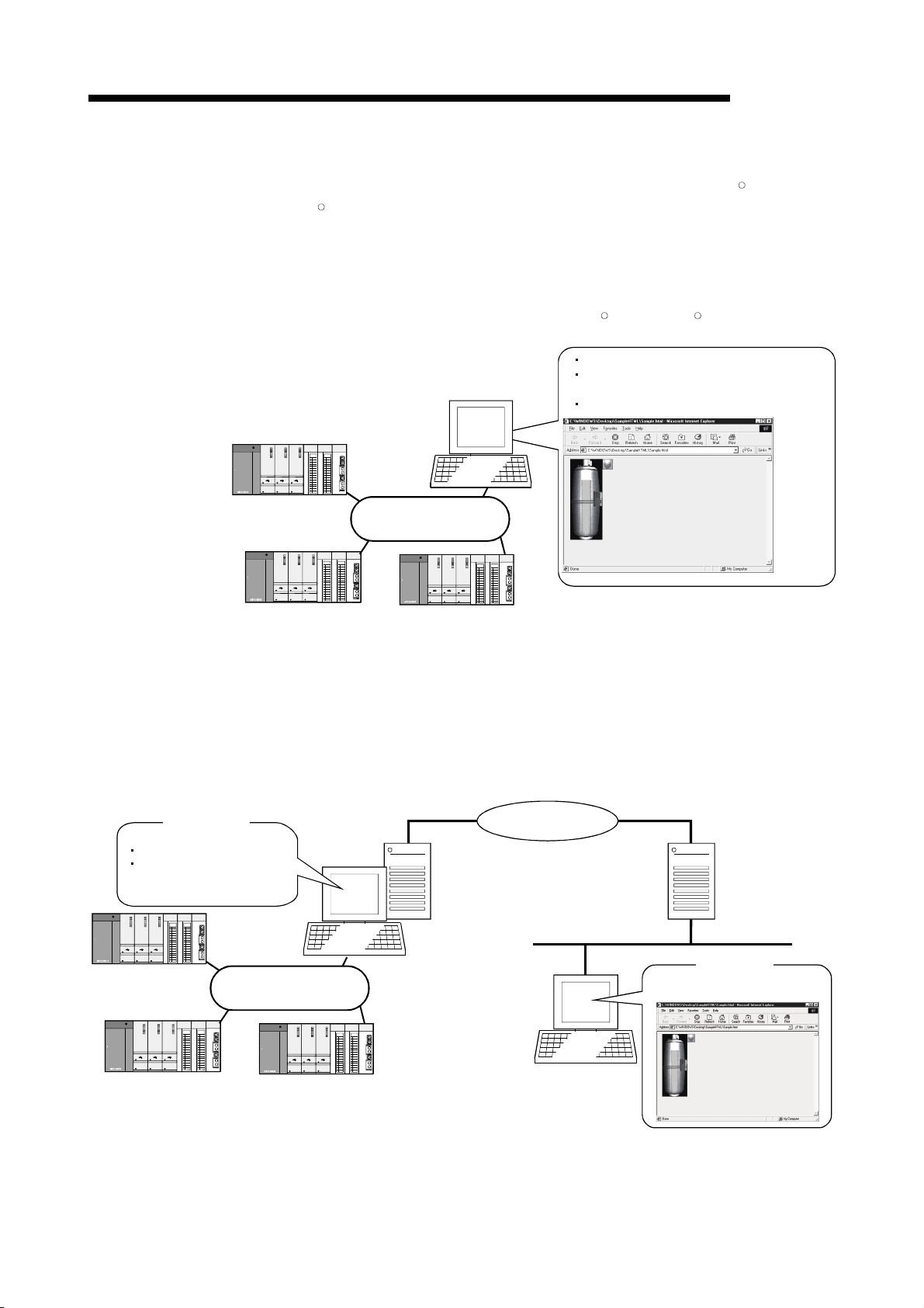
1 OVERVIEW
MELSOFT
(9) A wide variety of programming languages supported
MX Component supports VBScript and VBA as well as Visual BasicRand Visual
R
.
C++
(a) Creation of monitoring page using VBScript
1) Monitoring page can be created in HTML format
Using the text editor, you can create a graphical monitoring home
page (HTML format).
You need not purchase Visual Basic
R
, Visual C++Ror like.
Monitoring using Internet Explorer
MX Component
Web browser
Internet Explorer 5.0 or later
HTML for programmable controller monitoring
<Factory side>
MX Component
programmable controller
accessing ASP
MELSECNET/H or like
MELSECNET/H or like
2) Using ASP function for monitoring via Internet/intranet
Using the ASP function of VBScript to make public the Web pages on
the factory side (side which monitors data using MX Component)
enables the programmable controller device status or fault occurrence
time remote operation to be performed from a remote location or
business destination via the Internet/intranet by merely specifying the
factory side URL on Internet Explorer.
Internet
Intranet
Web server *1
*1: Web server supported by OS
(Internet Information Server,
Personal Web Server, etc.)
<Office side>
Web browser
Internet Explorer 5.0 or later
1 - 4 1 - 4
Page 37

1 OVERVIEW
MELSOFT
(b) VBA-driven data collection and monitoring function
Programming using VBA allows Excel or Access functions to be utilized to
create an application for providing a real-time graph display.
You can log the device data of the programmable controller and
collect/save the device data in real time.
<Excel>
<Access>
(10) Compatibility with multi-CPU system of QCPU (Q mode)
Setting the communication setting utility or ACT control properties enables
access to the multi-CPU system.
(11) Operability on PC CPU module
Q series bus communication from the PC CPU module enables access to the
QCPU (Q mode) on the same base.
Using the MELSECNET/H communication control and CC-Link communication
control enables access to other stations via the MELSECNET/H module and CCLink module controlled by the PC CPU module.
QCPU (Q mode)
PC CPU
module
MELSECNET/H
QCPU (Q mode) or like
CC-Link
QCPU (Q mode) or like
1 - 5 1 - 5
Page 38

1 OVERVIEW
MELSOFT
(12) Accessibility to gateway devices of GOT
Using the gateway function communication of MX Component can read/write the
gateway device data of the GOT.
Reading/writing the gateway device data of the GOT can read/write the device
data of the programmable controller CPU that is being monitored by the GOT.
MX
Component
Gateway device data of GOT can be
read/written using MX Component
Ethernet
(gateway functions).
GOT
GOT GOT
Programmable controller
CPU data are
read/written with GOT.
Mitsubishi
Programmable
controller
Company A
Programmable
controller
Company B
Programmable
controller
(13) Compatibility with GOT transparent function
Using the GOT transparent function, you can access the programmable
controller CPU via GOT
MX
Component
GOT
(14) Reduction of error definition search time
The ActSupport control for troubleshooting function is supported.
The error definition and corrective action appear within the user application by
only specifying the error code.
This eliminates the need to find the error definition or corrective action by
referring to the programming manual, if an error occurs in ACT control.
<Example of displaying error definition in message box>
Error definition and corrective action are displayed.
1 - 6 1 - 6
Page 39

2 SYSTEM CONFIGURATIONS
MELSOFT
2 SYSTEM CONFIGURATIONS
This chapter explains the system configurations, operating environment and usable
CPUs of MX Component.
2.1 System Configuration List
This section lists the systems that may be configured for each operating system.
2.1.1 When using Windows NTRWorkstation Operating System Version 4.0
The following table lists the systems that may be configured for the use of Windows
R
Workstation 4.0.
NT
Item Description
Computer link communication
Ethernet communication
CPU COM communication
CPU USB communication
MELSECNET/10 communication
MELSECNET/H communication
CC-Link IE Controller Network communication
CC-Link IE Field Network communication
CC-Link communication
CC-Link G4 communication
CPU board communication
Q series bus communication
(only when PC CPU module is used)
GX Simulator communication
GX Simulator2 communication
Modem communication
Gateway function communication
GOT transparent communication
*1: Does not support the used OS.
POINT
Use GX Developer and GX Simulator of the following version or later when making
GX Simulator communication.
• GX Developer Version 5 (SW5D5C-GPPW-E)
• GX Simulator (SW5D5C-LLT-E 10B)
Usable board
Usable driver
Usable board
Usable driver
Usable board
Usable driver
Usable board
Usable driver
Serial
USB
MELSECNET/10 board
SW2DNF-MNET10 or later
MELSECNET/H board
SW0DNC-MNETH-B or later
CC-Link board
SW2DNF-CCLINK or later
CPU board
SW0DNF-ANU-B or later
: Configurable : Not configurable
*1
2
2 - 1 2 - 1
Page 40

2 SYSTEM CONFIGURATIONS
2.1.2 When using WindowsR95 Operating System
MELSOFT
2
The following table lists the systems that may be configured for the use of
R
Windows
Computer link communication
Ethernet communication
CPU COM communication
CPU USB communication
MELSECNET/10 communication
MELSECNET/H communication
CC-Link IE Controller Network communication
CC-Link IE Field Network communication
CC-Link communication
CC-Link G4 communication
CPU board communication
Q series bus communication
(only when PC CPU module is used)
GX Simulator communication
GX Simulator2 communication
Modem communication
Gateway function communication
GOT transparent communication
95.
Item Description
*1
Usable board MELSECNET/10 board
Usable driver SW2DNF-MNET10 or later
Usable board MELSECNET/H board
Usable driver SW0DNC-MNETH-B or later
Usable board CC-Link board
Usable driver SW2DNF-CCLINK or later
Serial
USB
: Configurable : Not configurable
*1: Does not support the used OS.
POINT
(1) On WindowsR95, a memory leak will occur if any of the following
communications is made using the COM port. Therefore, do not perform
continuous operation.
• Computer link communication
• CPU COM communication
• CC-Link G4 communication
• Modem communication
(2) Use GX Developer and GX Simulator of the following version or later when
making GX Simulator communication.
• GX Developer Version 5 (SW5D5C-GPPW-E)
• GX Simulator (SW5D5C-LLT-E 10B)
2 - 2 2 - 2
Page 41

2 SYSTEM CONFIGURATIONS
2.1.3 When using WindowsR98 Operating System
MELSOFT
The following table lists the systems that may be configured for the use of
R
Windows
98.
Item Description
Computer link communication
Ethernet communication
CPU COM communication
CPU USB communication
MELSECNET/10 communication
MELSECNET/H communication
CC-Link IE Controller Network communication
CC-Link IE Field Network communication
CC-Link communication
CC-Link G4 communication
CPU board communication
Q series bus communication
(only when PC CPU module is used)
GX Simulator communication
GX Simulator2 communication
Modem communication
Gateway function communication
GOT transparent communication
Usable board MELSECNET/10 board
Usable driver SW2DNF-MNET10 or later
Usable board MELSECNET/H board
Usable driver SW0DNC-MNETH-B or later
Usable board CC-Link board
Usable driver SW2DNF-CCLINK or later
: Configurable : Not configurable
POINT
Use GX Developer and GX Simulator of the following version or later when making
GX Simulator communication.
• GX Developer Version 5 (SW5D5C-GPPW-E)
• GX Simulator (SW5D5C-LLT-E 10B)
2 - 3 2 - 3
Page 42
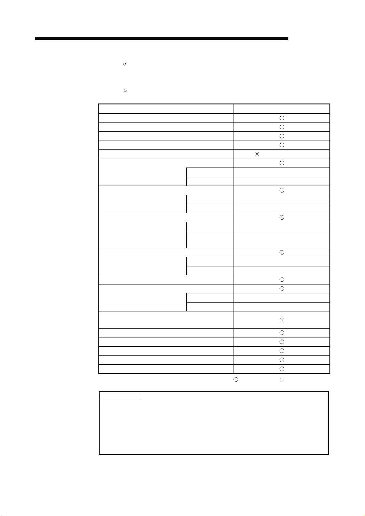
2 SYSTEM CONFIGURATIONS
2.1.4 When using WindowsR2000 Professional Operating System
MELSOFT
The following table lists the systems that may be configured for the use of
R
Windows
2000 Professional.
Item Description
Computer link communication
Ethernet communication
CPU COM communication
CPU USB communication
MELSECNET/10 communication
MELSECNET/H communication
CC-Link IE Controller Network
communication
CC-Link IE Field Network
communication
CC-Link communication
CC-Link G4 communication
CPU board communication
Q series bus communication
(only when PC CPU module is used)
GX Simulator communication
GX Simulator2 communication
Modem communication
Gateway function communication
GOT transparent communication
(Refer to POINT 2).)
Usable board MELSECNET/H board
Usable driver SW0DNC-MNETH-B or later
Usable board CC-Link IE Controller Network board
Usable driver SW1DNC-MNETG-B or later
Usable board CC-Link IE Field Network board
Usable driver
Usable board CC-Link board
Usable driver SW4DNF-CCLINK or later
Usable board CPU board
Usable driver SW1DNF-ANU-B or later
SW1DNC-CCIEF-J,
SW1DNC-CCIEF-B or later
: Configurable : Not configurable
POINT
(1) Use GX Developer and GX Simulator of the following version or later when
making GX Simulator communication.
• GX Developer Version 7 (SW7D5C-GPPW-E)
• GX Simulator Version 6 (SW6D5C-LLT-E)
(2) Use the MELSECNET/H board (NET/10 mode), as the MELSECNET/10 board
is incompatible.
2 - 4 2 - 4
Page 43

2 SYSTEM CONFIGURATIONS
2.1.5 When using WindowsRMillennium Edition Operating System
MELSOFT
The following table lists the systems that may be configured for the use of
R
Windows
Me.
Item Description
Computer link communication
Ethernet communication
CPU COM communication
CPU USB communication
MELSECNET/10 communication
MELSECNET/H communication
CC-Link IE Controller Network communication
CC-Link IE Field Network communication
CC-Link communication
CC-Link G4 communication
CPU board communication
Q series bus communication
(only when PC CPU module is used)
GX Simulator communication
GX Simulator2 communication
Modem communication
Gateway function communication
GOT transparent communication
: Configurable : Not configurable
POINT
(1) Use GX Developer and GX Simulator of the following version or later when
making GX Simulator communication.
• GX Developer Version 7 (SW7D5C-GPPW-E)
• GX Simulator Version 6 (SW6D5C-LLT-E)
(2) The ASP function of VBScript cannot be used.
2 - 5 2 - 5
Page 44

2 SYSTEM CONFIGURATIONS
2.1.6 When using WindowsRXP Professional Operating System
MELSOFT
The following table lists the systems that may be configured for the use of
R
Windows
XP Professional.
Item Description
Computer link communication
Ethernet communication
CPU COM communication
CPU USB communication
MELSECNET/10 communication
MELSECNET/H communication
CC-Link IE Controller Network
communication
CC-Link IE Field Network
communication
CC-Link communication
CC-Link G4 communication
CPU board communication
Q series bus communication
(only when PC CPU module is used)
GX Simulator communication
GX Simulator2 communication
Modem communication
Gateway function communication
GOT transparent communication
Usable board CC-Link IE Controller Network board
Usable driver SW1DNC-MNETG-B or later
Usable board CC-Link IE Field Network board
Usable driver
: Configurable : Not configurable
(Refer to POINT.)
SW1DNC-CCIEF-J,
SW1DNC-CCIEF-B or later
*1
*2
*1: Usable only when communication driver SW0DNC-MNETH-B Version 70H or later
is used.
*2: Usable only when communication driver SW4DNF-CCLINK-B Version 40E or later
is used.
POINT
Use the MELSECNET/H board (NET/10 mode), as the MELSECNET/10 board is
incompatible.
2 - 6 2 - 6
Page 45

2 SYSTEM CONFIGURATIONS
2.1.7 When using WindowsRXP Home Edition Operating System
MELSOFT
The following table lists the systems that may be configured for the use of
R
Windows
XP Home Edition.
Item Description
Computer link communication
Ethernet communication
CPU COM communication
CPU USB communication
MELSECNET/10 communication
MELSECNET/H communication
CC-Link IE Controller Network
communication
CC-Link IE Field Network
communication
CC-Link communication
CC-Link G4 communication
CPU board communication
Q series bus communication
(only when PC CPU module is used)
GX Simulator communication
GX Simulator2 communication
Modem communication
Gateway function communication
GOT transparent communication
Usable board CC-Link IE Controller Network board
Usable driver SW1DNC-MNETG-B or later
Usable board CC-Link IE Field Network board
Usable driver
SW1DNC-CCIEF-J,
SW1DNC-CCIEF-B or later
: Configurable : Not configurable
POINT
The ASP function of VBScript cannot be used.
2 - 7 2 - 7
Page 46

2 SYSTEM CONFIGURATIONS
2.1.8 When using Windows VistaROperating System
The following table lists the systems that may be configured for the use of Windows
R
.
Vista
Item Description
Computer link communication
Ethernet communication
CPU COM communication
CPU USB communication
MELSECNET/10 communication
MELSECNET/H communication
CC-Link IE Controller Network communication
CC-Link IE Field Network communication
CC-Link communication
CC-Link G4 communication
CPU board communication
Q series bus communication
(only when PC CPU module is used)
GX Simulator communication
GX Simulator2 communication
Modem communication
Gateway function communication
GOT transparent communication
MELSOFT
: Configurable : Not configurable
2 - 8 2 - 8
Page 47

2 SYSTEM CONFIGURATIONS
2.1.9 When using WindowsR7 Operating System
The following table lists the systems that may be configured for the use of WindowsR7.
Item
Computer link communication
Ethernet communication
CPU COM communication
CPU USB communication
MELSECNET/10 communication
MELSECNET/H communication
CC-Link IE Controller Network communication
CC-Link IE Field Network communication
CC-Link communication
CC-Link G4 communication
CPU board communication
Q series bus communication
(only when PC CPU module is used)
GX Simulator communication
GX Simulator2 communication
Modem communication
Gateway function communication
GOT transparent communication
MELSOFT
Description
32-bit version 64-bit version
: Configurable : Not configurable
2 - 9 2 - 9
Page 48

2 SYSTEM CONFIGURATIONS
2.2 System Configuration for the Use of Each Connection Form
This section provides the system configurations for the use of MX Component on a
communication form basis.
For details and precautions on each communication form, refer to Section 2.2.2.
2.2.1 System configurations
IBM-PC/AT compatible
MELSOFT
Computer link
communication
(Serial communication)
Ethernet
communication
CPU COM
communication
CPU USB
communication
MELSECNET/10
communication
RS-232
RS-232/RS-485 conversion
Ethernet
Ethernet
board
CC-Link IE Field Network
Ethernet adapter module
CC-Link IE Field
RS-232, RS-232/RS-422 conversion
Converter/cable
USB
MELSECNET/10
board
MELSECNET/10
(MELSECNET/H board (MELSECNET/10 mode))
Network
Computer link module
(Serial communication module)
FX extended port
(FX***-485-BD,FX***-485ADP)
Ethernet module
Built-in Ethernet port CPU, Q12DCCPU-V
CC-Link IE Field
Network module
ACPU, QnACPU, QCPU(Q mode),
QCPU(A mode), LCPU, FXCPU,
motion controller CPU
FXCPU
0/FX0S/FX0N/FX1S/FX1N/FX2N/
(FX
1NC
FX
/FX
2NC
/FX3G/FX3U/FX
3UC
)
QCPU (Q mode), Q12DCCPU-V,
LCPU, FXCPU(FX
MELSECNET/10 module
MELSECNET/H module
3G)
(MELSECNET/10 mode)
MELSECNET/H
communication
CC-Link IE Controller
Network
communication
CC-Link IE Field
Network
communication
CC-Link
communication
CC-Link G4
communication
CPU board
communication
MELSECNET/H
board
CC-Link IE Controller
Network bo ard
CC-Link I E Field
Network board
CC-Link
board
RS-232/RS-422
conversion
(Software version "D" or later)
CC-Link G4
module
MELSECNET/H
CC-Link IE Controller
Network
CC-Link IE Field
Network
CC-Link
CC-Link
MELSECNET/H module
CC-Link IE controller
Network module
CC-Link IE Field
Network module
CC-Link module
(Software version "N" or later)
CC-Link module
(Software version "N" or later)
CPU board equivalent
to A2USHCPU-S1
2 - 10 2 - 10
Page 49
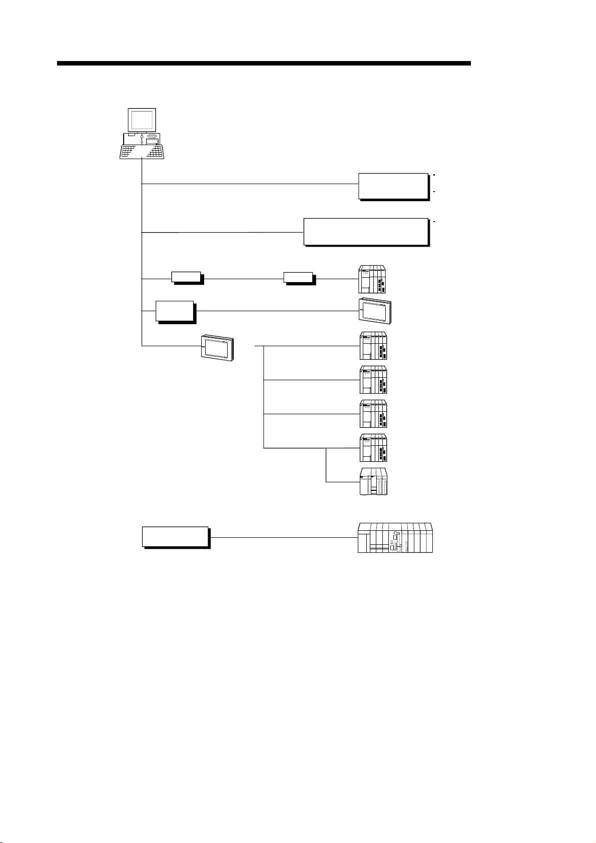
2 SYSTEM CONFIGURATIONS
MELSOFT
GX Simulator
communication
GX Simulator2
communication
Modem
communication
Gateway function
communication
GOT transparent
communication
IBM-PC/AT compatible
Ethernet
board
USB, RS-232
Ethernet
Modem
Telephone line
GOT
GX Developer
+ GX Simulator
(offline debugging)
Simulation function of GX Works2
Modem
Ethernet
RS-232
RS-232 Q series-compatible C24,
(GX Simulator2)
A6TEL,Q6TEL,FXCPU,QC24N,
Q series-compatible C24,
L series-compatible C24
GOT
ACPU,QnACPU,QCPU (Q mode),
QCPU (A mode),Q12DCCPU-V,LCPU,
FXCPU, motion controller CPU
L series-compatible C24
GX Developer Version 5
(SW5D5C-GPPW-E) or later
GX Simulator
(SW5D5C-LLT-E 10B) or later
Must be purchased separately.
GX Works2 Version 1
(SW1DNC-GXW2-E) or later
Must be purchased separately
Q series bus
communication
PC CPU module
Bus connection
On the same base
Ethernet
ACPU,QnACPU,QCPU (Q mode),
Q12DCCPU-V,
motion controller CPU
Ethernet module
Built-in Ethernet port CPU,Q12DCCPU-V
QCPU (Q mode)
2 - 11 2 - 11
Page 50

2 SYSTEM CONFIGURATIONS
2.2.2 Details of the communication forms
The table at top right of each communication format explanation indicates whether the
communication format can be made up when the OSes are used.
(Example) Windows NT
not supported.
R
Windows
Windows Vista
NT 95 98 2000 Me XP Vista 7(32) 7(64)
98, WindowsR2000 Professional, WindowsRMe, WindowsRXP,
NT: Windows NT
2000: Windows
Vista: Windows Vista
7(32): 32-bit Windows
: Configurable : Not configurable
(1) Computer link communication
NT 95 98 2000 Me XP Vista 7(32) 7(64)
For the way to make connection to the computer link module, refer to the manual
of your computer link module.
(a) Precaution
Computer link communication made on WindowsR95 will cause a memory
leak. Therefore do not perform continuous operation.
(b) Usable modules
1) Any of the following computer link modules may be used
to access the programmable controller CPU.
Usable Modules
C24
UC24
QC24(N)
Q series-compatible C24
L series-compatible C24
FX extended port
*1: Handled as equivalent to the UC24.
*2: Modules of software version "M" or later are handled as equivalent
to the UC24.
*3: Modules of software version "K" or later are handled as equivalent
to the UC24.
MELSOFT
R
Workstation 4.0, WindowsR95, and 64-bit WindowsR7 are
R
, and 32-bit WindowsR7 are supported.
R
Workstation 4.0, 95: WindowsR95, 98: WindowsR98,
R
2000 Professional, Me: WindowsRMe, XP: WindowsRXP,
R
,
R
7, 7(64): 64-bit WindowsR7
A1SCPUC24-R2*1, A1SJ71C24-PRF*2,
A1SJ71C24-R2*2, A1SJ71C24-R4*2, A2CCPUC24*3,
A2CCPUC24-PRF*3, AJ71C24-S6, AJ71C24-S8
AJ71UC24, A1SJ71UC24-R2, A1SJ71UC24-R4,
A1SJ71UC24-PRF
AJ71QC24, AJ71QC24-R2, AJ71QC24-R4,
A1SJ71QC24, A1SJ71QC24-R2, AJ71QC24N,
AJ71QC24N-R2, AJ71QC24N-R4, A1SJ71QC24N,
A1SJ71QC24N-R2
QJ71C24, QJ71C24-R2, QJ71C24N, QJ71C24N-R2,
QJ71C24N-R4
LJ71C24, LJ71C24-R2
FX0N-485ADP, FX2NC-485ADP, FX3U-485ADP,
FX
1N-485-BD, FX2N-485-BD, FX3G-485-BD,
FX
3U-485-BD
2 - 12 2 - 12
Page 51

2 SYSTEM CONFIGURATIONS
2) About connection of usable modules
Type Interface
A2CCPUC24
A2CCPUC24-PRF
AJ71C24-S6
AJ71C24-S8
A1SCPUC24-R2
A1SJ71C24-PRF
A1SJ71C24-R2
A1SJ71C24-R4 RS-422/485
AJ71UC24
A1SJ71UC24-R2
A1SJ71UC24-PRF
A1SJ71UC24-R4 RS-422/485
AJ71QC24/AJ71QC24N
A1SJ71QC24/A1SJ71QC24N
MELSOFT
When a computer link module is used to make access from the IBMPC/AT compatible to the programmable controller CPU, note that three
are restrictions on the modules connectable directly to the IBM-PC/AT
compatible.
If the module cannot be connected directly to the IBM-PC/AT
compatible, it may be used as the "n"th module of multidrop.
Multidrop
RS-232
RS-422
RS-422/485
RS-232
RS-422
RS-232
RS-232
RS-422/485
RS-232
RS-232
RS-422/485
1:1
Connection
First module "n"th module
AJ71QC24-R2
A1SJ71QC24-R2
AJ71QC24N-R2
A1SJ71QC24N-R2
AJ71QC24-R4
AJ71QC24N-R4
QJ71C24/QJ71C24N
QJ71C24-R2/QJ71C24N-R2
QJ71C24N-R4
LJ71C24
LJ71C24-R2
FX0N-485ADP
FX
2NC-485ADP
FX
3U-485ADP
FX
1N-485-BD
FX
2N-485-BD
FX3G-485-BD
FX
3U-485-BD
RS-232(CH.1)
RS-232(CH.2)
RS-422
RS-422/485
RS-232
RS-422/485
RS-232(CH.1)
RS-232(CH.2)
RS-422/485(CH.1)
RS-422/485(CH.2)
RS-232
RS-422/485
RS-232(CH.1)
RS-232(CH.2)
RS-422/485
*1
*1: Function Version B or later is compatible.
2 - 13 2 - 13
Page 52

2 SYSTEM CONFIGURATIONS
(c) Switch settings of the computer link module
For the switch settings for the use of MX Component, refer to "Section 6.1.1
Switch settings of computer link modules".
(d) Cable for connection
For the connection cable, refer to the manual of your computer link module.
Refer to Appendix 3 for cable pin assignment.
POINT
Only the RS-232 connector may be used for connection of the IBM-PC/AT
compatible and computer link (serial communication) module.
The RS-422 connector or RS-422/485 terminal block cannot be used.
(2) Ethernet communication
1) In case of using Ethernet interface modules
For the way to make connection to the Ethernet module, refer to the manual of
your Ethernet module.
(a) Precaution
The accessible range for Ethernet communication is the same segment only.
Access cannot be made beyond the router and gateway.
(b) Usable modules
Any of the following Ethernet modules may be used to access the
programmable controller CPU.
For the FX series Ethernet module, refer to the user’s manuals for the FX
E71 *1
QE71 *2
Q series-compatible E71 QJ71E71, QJ71E71-B2, QJ71E71-B5, QJ71E71-100
series.
Usable Modules
*1: Accessible as equivalent to the AnACPU when fitted to the AnUCPU.
*2: An error will occur if monitoring via QnA Ethernet and monitoring via
MELSOFT
NT 95 98 2000 Me XP Vista 7(32) 7(64)
AJ71E71, AJ71E71-S3, A1SJ71E71-B2, A1SJ71E71-B5,
A1SJ71E71B2-S3, A1SJ71E71B5-S3, AJ71E71N-T,
AJ71E71N-B5, AJ71E71N-B2, AJ71E71N-B5T, AJ71E71N3-T,
A1SJ71E71N-T, A1SJ71E71N3-T, A1SJ71E71N-B5,
A1SJ71E71N-B2, A1SJ71E71N-B5T
AJ71QE71, AJ71QE71-B5, A1SJ71QE71-B2, A1SJ71QE71-B5,
AJ71QE71N-T, AJ71QE71N-B5, AJ71QE71N-B2,
AJ71QE71N3-T, AJ71QE71N-B5T, A1SJ71QE71N-T,
A1SJ71QE71N3-T, A1SJ71QE71N-B5, A1SJ71QE71N-B2,
A1SJ71QE71N-B5T
other communication path are executed for the same CPU
simultaneously.
2 - 14 2 - 14
Page 53

2 SYSTEM CONFIGURATIONS
(c) Switch settings of the Ethernet module
For the switch settings for the use of MX Component, refer to "Section 6.2.1
Switch settings of Ethernet modules".
2) In case of using Built-in Ethernet port QCPUs
For the way to make connection to the Built-in Ethernet port QCPU, refer to the
manual of your Built-in Ethernet port QCPU.
(a) Precaution
The accessible range for the direct connection without specifying the IP
address is the same segment only.
Access cannot be made beyond the router and gateway.
(3) CPU COM communication
(a) Precaution
CPU COM communication made on WindowsR95 will cause a memory
leak. Therefore do not perform continuous operation.
(b) Cables for connection
1) Cable for connection of QCPU(Q mode) , LCPU, and
MELSOFT
NT 95 98 2000 Me XP Vista 7(32) 7(64)
NT 95 98 2000 Me XP Vista 7(32) 7(64)
QCPU(A mode)
The following cable is needed to make communications between the
IBM-PC/AT compatible and of QCPU(Q mode) and QCPU(A mode).
RS232 adaptor (L6ADP-R2) is needed for the connection of LCPU.
When communication is to be made at 115200bps or 57600bps, fast
communication cannot be performed if the used IBM-PC/AT
compatible does not support 115200bps or 57600bps communication
speed.
If a communication error occurs, reduce the transmission speed
setting and restart communication.
Cable
QC30R2 (Connector of IBM-PC/AT compatible is D-sub 9-pin)
2 - 15 2 - 15
Page 54

)
2 SYSTEM CONFIGURATIONS
2) Cables for connection of ACPU, QnACPU or FXCPU
IBM-PC/AT Compatible Side
(RS-232C Cable)
F2-232CAB-1*1
(When connector of IBM-PC/AT compatible
is D-sub 9-pin)
MELSOFT
The following cables are needed to make communications between
the IBM-PC/AT compatible and ACPU, QnACPU or FXCPU.
RS-232C/RS422
Converter
FX-232AW
FX-232AWC
For ACPU, QnACPU or FX1/FXU/FX2CCPU
FX-422CAB (0.3m/0.98feet)
FX-422CAB-150 (1.5m/4.92feet)
For FX
FX
3G/FX3U/FX3UCCPU
Programmable controller Side
(RS-422 Cable)
0/FX0S/FX0N/FX1N//FX1NC/FX1S/FX2N/FX2NC/
FX-232AWC-H
FX-422CAB0 (1.5m/4.92feet)
(FX series only)
*1: How to identify compatible product of F2-232CAB-1 cable
Check the indication on the type label attached to the cable.
Incompatible product Indicates as a compatible product (with indication of F/FX/A
F2-232CAB-1
Y990C
F2-232CAB-1(F/FX/A)
Y990C
• When connecting to the FX
the FX-232AWC-H, select any of 9600bps, 19200bps, 38400bps,
57600bps or 115200bps for the transmission speed.
When connecting using the FX-232AWC or FX-232AW, select either
9600bps or 19200bps for the transmission speed.
3) Cables for connection of motion controller CPU
For communications between the IBM-PC/AT compatible and motion
controller CPU, use the cables as indicated in 2).
4) Converter/Cable (FX CPU compatible) for connecting to
the USB on personal computer
• Applicable devices
FX-USB-AW USB cable (Included with the product)
FX
PWSDRD
(RS-422)
MITSUBISHI
FX-USB-AW
• Above devices can be used when the driver included in the product
(CD-ROM) has been installed into either of the following operating
R
systems; Windows
R
Windows
XP, Windows VistaR, and 32-bit WindowsR7.
98, WindowsRMe, WindowsR2000 Professional,
3GCPU, FX3UCPU or FX3UCCPU using
B
2 - 16 2 - 16
Page 55

2 SYSTEM CONFIGURATIONS
5) USB cable and function expansion board (FX3U, FX3UC
compatible)
a) System configuration
FX-USB-BD USB cable (packed)
MELSOFT
b) If "Operate communication setting" is checked on the <<PLC
System (2)>> tab in the [FX Parameter] dialog box of GX
Developer, the corresponding port cannot be used for
communication with the programmable controller.
In this case, write the setting, where the above setting has been
removed, from the built-in programming port of the programmable
controller.
When the CPU type of the project is the FX
3UC, the channel
specification (CH1/CH2) combo box is displayed. Set to CH1 and
check the settings.
R
c) When Windows
Windows
R
98, WindowsRMe, WindowsR2000 Professional,
XP, Windows VistaR, or 32-bit WindowsR7 is used, the
USB cable and function expansion board are available if the driver
on the CD-ROM packed with the FX-USB-AW or FX
3U -USB-BD
has been installed.
d) The USB cable and function expansion board are unavailable for
R
Windows
e) For the precautions and restrictions on use of the FX
refer to the manual packed with the FX
95 or Windows NTRWorkstation 4.0.
3U-USB-BD,
3U-USB-BD.
2 - 17 2 - 17
Page 56

2 SYSTEM CONFIGURATIONS
6) Function expansion board for FXCPU
MELSOFT
Series Function expansion board
FX3U, FX3UC FX3U-422-BD
FX3G FX3G-422-BD
FX2N FX2N-422-BD
FX1S, FX1N FX1N-422-BD
If "Operate communication setting" is checked on the <<PLC system
(2)>> tab in the "FX Parameter" dialog box of GX Developer, the
corresponding port cannot be used for communication with the
programmable controller. In this case, write the setting, where the
above setting has been removed, from the built-in programming port of
the programmable controller.
When the CPU type of the project is the FX
specification (CH1/CH2) combo box is displayed.
Set to CH1 and check the settings.
2 - 18 2 - 18
3G or FX3U(C), the channel
Page 57

2 SYSTEM CONFIGURATIONS
7) RS-232 cable and function expansion board (special
Serial port shape of
personal computer
D sub 9 pin
D sub 25 pin
Series Required function expansion board and special adaptor RS-232 cable
FX3U, FX3UC
FX3G
FX3U-232-BD
Function expansion board (FX
FX3G-232-BD
3G-CNV-ADP + FX3U-232ADP
FX
FX0N-232ADP + FX2N-CNV-BD F2-232CAB-1
FX2N
FX1NC, FX2NC
FX2N-232-BD
FX
2NC-232ADP + FX2N-CNV-BD
FX0N-232ADP F2-232CAB-1
2NC-232ADP FX-232CAB-1
FX
FX0N-232ADP + FX1N-CNV-BD F2-232CAB-1
FX
1S,
FX1N
FX3U, FX3UC
FX3G
FX1N-232-BD
FX
2NC-232ADP + FX1N-CNV-BD
FX3U-232-BD
Function expansion board (FX
FX3G-232-BD
3G-CNV-ADP + FX3U-232ADP
FX
FX0N-232ADP + FX2N-CNV-BD F2-232CAB
FX2N
FX1NC, FX2NC
FX2N-232-BD
FX
2NC-232ADP + FX2N-CNV-BD
FX0N-232ADP F2-232CAB
2NC-232ADP FX-232CAB-1
FX
FX0N-232ADP + FX1N-CNV-BD F2-232CAB
1S,
FX1N
FX
FX1N-232-BD
FX
2NC-232ADP + FX1N-CNV-BD
MELSOFT
adaptor) for FXCPU
FX-232CAB-1
FX-232CAB-1
FX-232CAB-1
FX-232CAB-1
FX-232CAB-1
F2-232CAB-1
FX-232CAB-1
FX-232CAB-1
3U-485-BD.
3U-***-BD) + FX3U-232ADP*
3U-***-BD) + FX3U-232ADP*
1
1
*1: *** of the function expansion board (FX3U-***-BD) indicates 232, 485, 422,
USB or CNV.
Regarding FX
3UC series, only FX3UC-32MT-LTCPU and FX3UC-32MT-LT-2
CPU are connectable.
The computer link communication is also available for the FX
For setting for the computer link communication, refer to Section 6.1.1 (4).
If "Operate communication setting" is checked on the <<PLC System
(2)>> tab in the "FX Parameter" dialog box of GX Developer, the
corresponding port cannot be used for communication with the
programmable controller.
In this case, write the setting, where the above setting has been
removed, from the built-in programming port of the programmable
controller.
2 - 19 2 - 19
Page 58

2 SYSTEM CONFIGURATIONS
POINT
• Before handling the RS-422 interface conversion cable/converter, please read its
specifications, precautions, etc. carefully in the manual of the corresponding
product and handle it correctly.
• When disconnecting or reconnecting the conversion cable/converter that receives
5VDC power from the RS-422 interface, power off the programmable controller
CPU before starting work.
• When disconnecting or reconnecting the peripheral device or conversion cable
that does not receive 5VDC power from the RS-422 interface (whose power is
supplied from an external power supply), be sure to use an earth band or touch a
grounded metal object, etc. before starting work to discharge static electricity from
the cable, human body, etc. After that, handle it in the following procedure.
1) Power off the personal computer.
2) Power off the conversion cable/converter.
When it has an FG terminal, ground it.
3) Connect/disconnect the conversion cable/converter between the personal
computer and programmable controller CPU.
4) Power on the conversion cable/converter.
5) Power on the personal computer.
6) Start up the software package.
MELSOFT
When the CPU type of the project is
the FX
3G or FX3U(C), the channel
specification (CH1/CH2) combo box is
displayed.
When using the FX
first FX
FX
3U-232ADP connected to the
3U-CNV-BD, set CH1 and check the
3U-232-BD or the
settings.
When using the FX
connected to other than the FX
CNV-BD or the second FX
connected to the FX
3U-232ADP
3U-
3U-232ADP
3U-CNV-BD, set
CH2 and check the settings.
2 - 20 2 - 20
Page 59

2 SYSTEM CONFIGURATIONS
(4) CPU USB communication
(a) Precautions
1) WindowsR98, WindowsR2000 Professional, WindowsRMe,
2) When using WindowsR2000 Professional, WindowsRXP,
(b) About the USB cable (QCPU (Q mode) compatible)
1) When the USB cable is used, only one programmable
2) Refer to "Operating Instructions" for the precautions for
(c) Usable modules
Refer to "Access Target" of the accessible device table in
Section 8.5.1.
MELSOFT
NT 95 98 2000 Me XP Vista 7(32) 7(64)
WindowsRXP, Windows VistaR, WindowsR7 may be used
when the USB driver has been installed.
Windows VistaR, WindowsR7, the user must install the
USB driver.
controller CPU may be connected.
and restrictions on use of the USB cable to make
communications.
2 - 21 2 - 21
Page 60

2 SYSTEM CONFIGURATIONS
(5) MELSECNET/10 communication
(a) Precautions
1) Always use any of the following communication drivers.
Windows NTRWorkstation 4.0
WindowsR95
WindowsR98
WindowsR2000 Professional
WindowsRMe
WindowsRXP Professional
WindowsRXP Home Edition
Windows VistaR
WindowsR7
(6) MELSECNET/H communication
(a) Precautions
MELSOFT
NT 95 98 2000 Me XP Vista 7(32) 7(64)
Other communication drivers cannot be used.
Used OS SW2DNF-MNET10 SW3DNF-MNET10
: Usable, : Unusable
NT 95 98 2000 Me XP Vista 7(32) 7(64)
1) As the communication driver, always use SW0DNCMNETH or later.
Any other communication driver is unusable.
2) For details of the supported operating system of the
network board to be used for communication, refer to the
manual of each network board.
(7) CC-Link IE Controller Network communication
NT 95 98 2000 Me XP Vista 7(32) 7(64)
(a) Precautions
1) As the communication driver, always use SW1DNCMNETG-B or later.
Any other communication driver is unusable.
2) For details of the supported operating system of the
network board to be used for communication, refer to the
manual of each network board.
2 - 22 2 - 22
Page 61

2 SYSTEM CONFIGURATIONS
(8) CC-Link IE Field Network communication
(a) Precautions
1) As the communication driver, always use SW1DNC-
2) For details of the supported operating system of the
(9) CC-Link communication
(a) Precautions
MELSOFT
NT 95 98 2000 Me XP Vista 7(32) 7(64)
CCIEF-J, SW1DNC-CCIEF-B or later.
Any other communication driver is unusable.
network board to be used for communication, refer to the
manual of each network board.
NT 95 98 2000 Me XP Vista 7(32) 7(64)
A80BDE-J61BT11/A80BDE-J61BT13
Used OS SW2DNF-CCLINK SW3DNF-CCLINK SW4DNF-CCLINK-B SW1DNC-CCBD2-B
Windows NTRWorkstation 4.0
WindowsR95
WindowsR98
WindowsR2000 Professional
WindowsRMe
WindowsRXP Professional
WindowsRXP Home Edition
Windows VistaR
32-bit WindowsR7
1) Always use any of the following communication drivers.
Other communication drivers cannot be used.
2) For details of the supported operating system of the
network board to be used for communication, refer to the
manual of each network board.
Q80BD-
J61BT11N
*1
*2
*3
: Usable, : Unusable
*1: Apply communication driver SW4DNF-CCLINK-B Version 40E or
R
later to Windows
XP Professional.
*2: Apply communication driver SW1DNC-CCBD2-B Version 1.04E or
R
later to Windows Vista
.
*3: Apply communication driver SW1DNC-CCBD2-B Version 1.08J or
R
later to 32-bit Windows
7.
Q81BD-
J61BT11
*2
*3
2 - 23 2 - 23
Page 62

2 SYSTEM CONFIGURATIONS
3) The following are the CPUs that can be accessed by the
CPU Type
A to V *1 W to *2 A to V *1 W to *2 A to V *1 W to *2 -
ACPU (including motion controller CPU)
QCPU(A mode)
QnACPU
QCPU(Q mode)
LCPU
4) The CC-Link master station module used should be of
(10) CC-Link G4 communication
(a) Precautions
1) Computer link communication made on WindowsR95 will
2) The CC-Link G4 module used should be of software
MELSOFT
communication drivers.
SW2DNF-CCLINK SW3DNF- CCLINK SW4DNF-CCLINK-B
: Accessible, : Inaccessible
*1: For ROM versions "A" to "V" of CC-Link board
*2: For ROM versions "W" and later of CC-Link board
*3: For Version 1.07H or later
SW1DNC-
CCBD2-B
*3
software version "N" or later.
NT 95 98 2000 Me XP Vista 7(32) 7(64)
cause a memory leak. Therefore do not perform
continuous operation.
version "D" or later.
3) The CC-Link master station module used should be of
software version "N" or later.
(b) Switch settings of the CC-Link G4 module
For the switch settings for the use of MX Component, refer to "Section 6.7.1
Switch settings of CC-Link G4 module".
(c) About cables
Communications between the IBM-PC/AT compatible and CC-Link G4
module require the RS-232/RS-422 conversion cables as used in CPU
COM communication.
For more information, refer to "(3) (b) 2) Cables for connection of ACPU,
QnACPU or FXCPU".
2 - 24 2 - 24
Page 63

2 SYSTEM CONFIGURATIONS
(11) CPU board communication
(a) Precautions
1) Always use any of the following communication drivers.
Windows NTRWorkstation 4.0
WindowsR95
WindowsR98
WindowsR2000 Professional
WindowsRMe
WindowsRXP Professional
WindowsRXP Home Edition
Windows VistaR
WindowsR7
2) Access to the QCPU (Q mode), LCPU and FXCPU cannot
(12) Q series bus communication (only when PC CPU module is used)
(a) Precautions
1)
MELSOFT
NT 95 98 2000 Me XP Vista 7(32) 7(64)
Other communication drivers cannot be used.
Used OS SW0DNF-ANU-B SW1DNF-ANU-B
: Usable, : Unusable
be made.
NT 95 98 2000 Me XP Vista 7(32) 7(64)
Use the MELSECNET/H communication and CC-Link
communication controls to make access to other stations
via the MELSECNET/H module and CC-Link module
controlled by the PC CPU module.
2 - 25 2 - 25
Page 64

2 SYSTEM CONFIGURATIONS
(13) GX Simulator communication
When making GX Simulator communication, use GX Developer and GX
Simulator of the following versions or later.
Used OS GX Developer GX Simulator
Windows NTRWorkstation 4.0
WindowsR95
WindowsR98
WindowsR2000 Professional
WindowsRMe
WindowsRXP Professional
WindowsRXP Home Edition
Windows VistaR
WindowsR7
POINT
GX Developer and GX Simulator must be purchased separately.
MELSOFT
NT 95 98 2000 Me XP Vista 7(32) 7(64)
Version 5 (SW5D5C-GPPW -E)
or later
Version 7 (SW7D5C-GPPW -E)
or later
Version 8 (SW8D5C-GPPW -E)
or later
Version 5 (SW5D5C-LLT-E 10B)
or later
Version 6 (SW6D5C-LLT-E)
or later
Version 7 (SW7D5C-LLT-E)
or later
(14) GX Simulator2 communication
NT 95 98 2000 Me XP Vista 7(32) 7(64)
When making GX Simulator2 communication, use GX Works2 Version1
(SW1DNC-GXW2) or later.
POINT
GX Works2 must be purchased separately.
2 - 26 2 - 26
Page 65

2 SYSTEM CONFIGURATIONS
MELSOFT
(15) Modem communication
NT 95 98 2000 Me XP Vista 7(32) 7(64)
(a) Precautions
1) When performing modem communication, make the
setting in the parameters and sequence program for the
connected module.
Use any of the following GX Developers to set the corresponding
Module GX Developer
A6TEL, Q6TEL, FXCPU, QC24N Version 3 (SW3D5C-GPPW-E/SW3D5F-GPPW-E) or later
Q series-compatible C24 Version 4 (SW4D5C-GPPW-E) or later
module.
2) For modem communication using the FXCPU, only the
FX1S, FX1N, FX1NC, FX2N, FX2NC, FX3G, FX3U, and FX3UC
are applicable.
3) Use the RS-232 cable supplied with the modem for
connection between the personal computer and modem.
(b) Modem specifications
When performing modem communication, select the modem that satisfies
the following specifications.
1) AT command compatibility (initialization command)
2) Only the DR terminal can be turned ON (High)
independently.
(Example: The modem where the CD terminal turns ON when only the
DR terminal is turned ON is not applicable.)
3) Communication Standards:
ITU-T V.90/V.34/V.32bis/V.32/V.22BIS/V.22/V.21/V.FC
POINT
(1) MX Component is not compatible with manual line connection (connection via
an operator).
Use a subscriber telephone line or private telephone line to perform modem
communication.
(2) It is required to set the COM port when performing modem communication by
using modem built in the personal computer or the PC card (PCMCIA).
For the COM port of the modem built in the personal computer or the PC card
(PCMCIA), refer to the manual of the corresponding product.
(3) For modem communication, the AT command, that is standard for some
modems, is not executable.
If the line cannot be connected by selecting "Modem standard" for "AT
command" within the communication settings utility, specify the AT command
on the user side.
Refer to Section 5.1.7 for the setting of "AT command" within the
communication settings utility.
(4) When using the callback function, use the Q Series Corresponding C24.
2 - 27 2 - 27
Bell 212A/103
Page 66

2 SYSTEM CONFIGURATIONS
(16) Gateway function communication
(a) Gateway function-compatible GOT
For the gateway function-compatible GOT, refer to the Operating Manual
(Gateway Functions) of the GOT.
(b) About GOT setting and setting between GOT and
programmable controller
For the GOT setting and the setting between the GOT and programmable
controller, refer to the Operating Manual (Gateway Functions) of the GOT.
(17) GOT transparent communication
Communicable via GOT1000 series only.
For GOT setting and the setting between GOT and programmable controller,
refer to the manual of GOT.
• GOT1000 Series Connection Manual
MELSOFT
NT 95 98 2000 Me XP Vista 7(32) 7(64)
NT 95 98 2000 Me XP Vista 7(32) 7(64)
*1 *1
*1: Cannot be communicated via USB connection.
2 - 28 2 - 28
Page 67
2 SYSTEM CONFIGURATIONS
2.3 Operating Environment
MELSOFT
The following table summarizes the operating environment for MX Component.
Item Description
IBM PC/AT
133MHz or more PentiumR*1 IBM PC/AT compatible personal computer where the OS
operates.
Computer
compatible
personal
computer
PC CPU module MELSEC-Q series compatible PC CPU module (CONTEC CO., LTD. make)
Required memory 32MB or more *2
Hard disk free space 100MB or more
Disk drive CD-ROM disk drive
Display Resolution 800 × 600 pixels or higher (1024 × 768 pixels or higher for Windows VistaR)
R
Microsoft
WindowsR2000 Professional Operating System (English version),
MicrosoftRWindowsRMillennium Edition Operating System (English version),
Microsoft
R
WindowsR95 Operating System (English version),
MicrosoftRWindowsR98 Operating System (English version),
MicrosoftRWindows NTRWorkstation Operating System Version 4.0 (English version) *3,
Microsoft
R
WindowsRXP Professional Operating System (English version) *4,
MicrosoftRWindowsRXP Home Edition (English version) *4,
MicrosoftRWindows VistaRHome Basic Operating System (English version),
System Software
Microsoft
R
Windows VistaRHome Premium Operating System (English version),
MicrosoftRWindows VistaRBusiness Operating System (English version),
MicrosoftRWindows VistaRUltimate Operating System (English version),
Microsoft
Microsoft
Microsoft
R
Windows VistaREnterprise Operating System (English version),
R
WindowsR7 Starter Operating System (English version),
R
WindowsR7 Home Premium Operating System (English version),
MicrosoftRWindowsR7 Professional Operating System (English version),
R
Microsoft
Microsoft
WindowsR7 Ultimate Operating System (English version) or
R
WindowsR7 Enterprise Operating System (English version)
(To the next page)
R
*1: Pentium
the use of Windows
Windows
*2: 64MB or more is recommended for Windows
Windows
more is recommended for 64-bit Windows
*3: Service Pack 3 or more is needed for the use of Windows NT
150MHz or more is recommended for the use of WindowsRMe, PentiumR300MHz or more for
R
R
7.
R
XP, 1GB or more is recommended for Windows VistaRand 32-bit WindowsR7, and 2GB or
XP, and 1GHz or more is recommended for the use of Windows VistaRand
R
2000 Professional, 128MB or more is recommended for
R
7.
R
Workstation 4.0.
*4: MX Component cannot be used in the XP compatibility mode.
2 - 29 2 - 29
Page 68

2 SYSTEM CONFIGURATIONS
Item Description
MELSOFT
Programming
language
Development software
MicrosoftRVisual BasicR6.0 (English version),
R
Visual BasicR.NET 2003 (English version),
R
Visual StudioR2005 Visual BasicR(English version) *8,
R
Visual StudioR2008 Visual BasicR(English version) *9 or
R
Visual StudioR2010 Visual BasicR(English version) *10
Visual BasicR
Microsoft
Microsoft
Microsoft
Microsoft
MicrosoftRVisual C++R6.0 (English version),
R
Visual C++R.NET 2003 (English version),
R
Visual StudioR2008 Visual C++R(English version) *9 or
R
Visual StudioR2010 Visual C++R(English version) *10
Programming language *5
Visual C++R
Microsoft
MicrosoftRVisual StudioR2005 Visual C++R(English version) *8,
Microsoft
Microsoft
VBScript *6, *7 Text editor and commercially available HTML tool
MicrosoftRExcel 2000 (English version),
R
Microsoft
Microsoft
Excel 2002 (English version) *11,
R
Excel 2003 (English version) *12,
MicrosoftRExcel 2007 (English version) *13 or
R
VBA
32-bit Microsoft
Microsoft
Microsoft
Microsoft
Microsoft
32-bit MicrosoftRAccess 2010 (English version) *14
Excel 2010 (English version) *14
R
Access 2000 (English version),
R
Access 2002 (English version) *11,
R
Access 2003 (English version) *12,
R
Access 2007 (English version) *13 or
*5: User programs created in the English environment may be used in the English environment only. They
cannot be used in the Japanese environment.
*6: To operate VBScript, use Internet Explorer (version 5.00.2919.6307 or later).
R
*7: When Windows
*8: Windows
Studio
R
2005.
R
When using Visual Studio
R
Studio
*9: Windows
2005 Service Pack 1 Update for W indows VistaRis required.
R
When using Visual Studio
*10: For Visual Studio
Windows
R
*11 When using Excel 2002 or Access 2002 on Windows
*12: When using Excel 2003 or Access 2003 on Windows
Me or WindowsRXP Home Edition is used, the ASP function is unusable.
2000 Service Pack 4 or later, or W indowsRXP Service Pack 2 or later is required for Visual
R
2005 on Windows VistaR, Visual StudioR2005 Service Pack 1 or Visual
XP Service Pack 2, Windows VistaRor later is required for Visual StudioR2008.
R
R
2010, WindowsRXP Service Pack 3, Windows VistaRService Pack 2 or higher, or
2008 on WindowsR7, Visual StudioR2008 Service Pack 1 is required.
7 or later is required.
R
7, WindowsRXP Service Pack 3 or later is required.
R
7, WindowsR2003 Service Pack 3 or later is
required.
R
*13: Windows
*14: For 32-bit Excel 2010 and 32-bit Access 2010, Windows
Pack 1 or higher, or Windows
XP Service Pack 2 or later is required for Excel 2007 or Access 2007.
R
R
7 or later is required.
XP Service Pack 3, Windows VistaRService
64-bit Excel 2010 and 64-bit Access 2010 are not supported.
2 - 30 2 - 30
Page 69

2 SYSTEM CONFIGURATIONS
POINT
(1) When WindowsRXP, Windows VistaRor WindowsR7 is used, the following
new functions cannot be used.
If any of the following new functions is used, this product may not operate
normally.
Start of application in Windows
Fast user switching
Remote desktop
Big fonts (Details setting of Screen properties)
64-bit Windows
(2) When Windows
Windows XP Mode
Windows Touch
(3) When creating a user program, select "x86" (32 bits) "Target CPU".
MELSOFT
R
compatible mode
R
XP and 64-bit Windows VistaRare not supported.
R
7 is used, the following new functions cannot be used.
2 - 31 2 - 31
Page 70

2 SYSTEM CONFIGURATIONS
2.4 Usable Programmable Controller CPUs
MELSOFT
Programmable controller CPU Types
ACPU
QnACPU
QCPU (A mode) Q02CPU-A, Q02HCPU-A and Q06HCPU-A.
QCPU (Q mode)
LCPU L02CPU, L26CPU-BT
FXCPU
Motion controller CPU A171SHCPU, A172SHCPU, A173UHCPU, A173UHCPU-S1, A273UHCPU, and A273UHCPU-S3.
QSCPU QS001CPU.
C controller CPU Q12DCCPU-V
The usable programmable controller CPUs are given below.
A0J2HCPU, A1SCPU, A1SCPU-S1, A1SCPUC24-R2, A1SHCPU, A1SJCPU, A1SJHCPU,
A1NCPU, A2CCPU, A2CCPUC24, A2CCPUC24-PRF, A2CJCPU, A2NCPU, A2NCPU-S1,
A2SCPU, A2SCPU-S1, A2SHCPU, A2SHCPU-S1, A3NCPU, A1FXCPU, A2ACPU, A2ACPU-S1,
A2ACPUP21/R21, A2ACPUP21/R21-S1, A3ACPU, A3ACPUP21/R21, A2UCPU, A2UCPU-S1,
A2USCPU, A2USCPU-S1, A2ASCPU, A2ASCPU-S1, A2ASCPU-S30, A2USHCPU-S1, A3UCPU,
and A4UCPU.
Q2ACPU, Q2ACPU-S1, Q2ASCPU, Q2ASCPU-S1, Q2ASHCPU, Q2ASHCPU-S1, Q3ACPU,
Q4ACPU, and Q4ARCPU.
Q00JCPU, Q00UJCPU, Q00CPU, Q00UCPU, Q01CPU, Q01UCPU, Q02CPU, Q02HCPU,
Q02PHCPU, Q02UCPU, Q03UDCPU, Q03UDECPU, Q04UDHCPU, Q04UDEHCPU, Q06HCPU,
Q06PHCPU, Q06UDHCPU, Q06UDEHCPU, Q10UDHCPU, Q10UDEHCPU, Q12HCPU,
Q12PHCPU, Q13UDHCPU, Q13UDEHCPU, Q20UDHCPU, Q20UDEHCPU, Q25HCPU,
Q25PHCPU, Q26UDHCPU, Q26UDEHCPU, Q50UDEHCPU, and Q100UDEHCPU.
FX
0CPU, FX0SCPU, FX0NCPU, FX1CPU, FX1NCPU, FX1NCCPU, FX1SCPU, FXUCPU, FX2CCPU,
FX
2NCPU, FX2NCCPU, FX3GCPU, FX3UCPU, and FX3UCCPU.
*1: Cannot be used when the first five digits of the serial number is 12042 or later.
2 - 32 2 - 32
Page 71

2 SYSTEM CONFIGURATIONS
MEMO
MELSOFT
2 - 33 2 - 33
Page 72

3 OPERATION PROCEDURES
3 OPERATION PROCEDURES
MELSOFT
This chapter explains the selection of the MX Component development type and the
procedures for creating user applications.
3.1 Selecting the Development Type
When using MX Component to create user applications, choose the utility setting type
3
or program setting type before creating a user application.
The utility setting type and program setting type will be described.
(1) Utility setting type
Setting Type
Item
Feature
Used ACT control ActEasyIF, ActMLEasyIF
Whether communication
setup utility is used or not
How to connect PLC
monitor utility
Make communication settings using the communication setting wizard.
Using the communication setup utility enables you to create a user program
without being aware of the complicated parameters of any communication.
In the user program, the communication line can be connected by simply setting
the logical station number set on the communication setting wizard to the ACT
control property or into a user program.
(2) Program setting type
A user program is created without using the communication setup utility.
Make ACT control settings for the corresponding communication in the property
window directly or within the user program.
The properties necessary to be set depend on the ACT control.
(3) Comparison
The following table compares the utility setting type and program setting type.
Communication settings can be made easily using
the communication setting wizard.
In program creation, communication can be made
by merely making the setting (logical station
number) on the communication setting wizard. (The
number of development processes can be reduced.)
Used. Not used.
Choose the logical station number.
Utility Setting Type Program Setting Type
All communication settings can be
made in the user program.
Communication settings can be
changed flexibly in the user program.
ACT control for corresponding
communication
Change the settings every time you
make connection. (Use the wizard)
3 - 1 3 - 1
Page 73

3 OPERATION PROCEDURES
MELSOFT
3.2 User Application Creating Procedures
3.2.1 When using Visual BasicR6.0/Visual BasicR.NET
The following creation procedures assumes use of Visual BasicR6.0/
Visual Basic
Power on the IBM-PC/AT compatible and start
Windows.
Install MX Component.
Make settings using the
utility setting type?
Yes
<Utility setting type>
Start the communication setup utility
and make communication settings
in accordance with the wizard.
Start Visual Basic 6.0/
Visual Basic .NET.
Register the ACT control to Visual
Basic 6.0/Visual Basic .NET.
Create a form and paste the control.
(ActEasyIF control)
Set the property of the pasted
control. (Set only the logical station
number)
R
R
RR
R
.NET.
No
Refer to the operating manual (startup).
Refer to
Section 5.1,
Chapter 6.
Refer to the
programming
manual.
Refer to
Chapter 6.
<Program setting type>
Start Visual Basic 6.0/
Visual Basic .NET.
Add the ACT controls to Visual
R
Basic 6.0/Visual Basic .NET.
Create a form and paste the ACT
controls for corresponding
communication.
Set the properties of the pasted
ACT controls.
R
R
R
Refer to the
programming
manual.
Refer to the
programming
manual and
Chapter 7.
3
Perform programming using the functions offered by
the corresponding ACT control.
Perform debugging
using the PLC monitor
utility?
No
Completion of user application
Yes
Refer to the programming manual.
Refer to "Section 3.3 PLC Monitor Utility Operating
Procedure".
3 - 2 3 - 2
Page 74

3 OPERATION PROCEDURES
3.2.2 When using Visual C++R6.0/Visual C++R.NET
MELSOFT
The following creation procedures assumes use of Visual C++R6.0/Visual C++R.NET.
Power on the IBM-PC/AT compatible and start
Windows .
Install MX Component.
Make settings using
the utility setting type?
Yes
<Utility setting type>
Start the communication setup utility
and make communication settings
in accordance with the wizard.
Start Visual C++ 6.0/
Visual C++ .NET.
Register the ACT control to Visual
C++ 6.0/Visual C++ .NET.
Create a form and paste the control.
(ActEasyIF control)
R
R
RR
No
Refer to
Section 5.1,
Chapter 6.
Refer to the
programming
manual.
Refer to the operating manual (startup).
<Program setting type>
Start Visual C++ 6.0/
Visual C++ .NET.
Add the ACT controls to Visual
R
C++ 6.0/Visual C++ .NET.
R
Create a form and paste the ACT
control for corresponding
communication.
Using Class Wizard, define the
pasted ACT control as a dialog
member.
R
R
Refer to the
programming
manual.
Using ClassWizard, define the
pasted ACT control as a dialog
member.
Set the property of the pasted
control. (Set only the logical station
number)
Perform programming using the functions offered by
the corresponding ACT control.
debugging using the PLC monitor
Perform
Yes
utility?
No
Completion of user application
Set the properties of the pasted
ACT control.
Refer to
Chapter 6.
Refer to the programming manual.
Refer to "Section 3.3 PLC Monitor Utility Operating
Procedure".
3 - 3 3 - 3
Page 75

3 OPERATION PROCEDURES
3.2.3 When using VBA
MELSOFT
The following creation procedures assumes use of VBA.
Power on the IBM-PC/AT compatible and start
Windows .
Install MX Component.
Make settings using
the utility setting type?
Yes
<Utility setting type>
Start the communication setup utility
and make communication settings
in accordance with the wizard.
Start Microsoft Excel or Microsoft
Access.
Start Visual Basic Editor and
create applications.
Generate the ActEasyIF control
so that MX Component may be
utilized on VBA.
No
Refer to
Section 5.1,
Chapter 6.
Refer to the
programming
manual.
Refer to the operating manual (startup).
<Program setting type>
Start Microsoft Excel or Microsoft
Access.
Start Visual Basic Editor and
create applications.
Generate the corresponding
communication control so that MX
Component may be utilized on VBA.
Set the property of the pasted
control.
Refer to the
programming
manual.
Refer to
Chapter 6.
Set the property of the pasted
control. (Set only the logical station
number)
Perform programming using the functions offered by
the corresponding ACT control.
debugging using the PLC monitor
Perform
utility?
No
Completion of user application
Yes
Refer to
Chapter 6.
Refer to the programming manual.
Refer to "Section 3.3 PLC Monitor Utility Operating
Procedure".
3 - 4 3 - 4
Page 76

3 OPERATION PROCEDURES
3.2.4 When using VBScript
MELSOFT
The following creation procedures assumes use of VBScript.
Power on the IBM-PC/AT compatible and start
Windows .
Install MX Component.
Make settings using
the utility setting type?
Yes
<Utility setting type>
Start the communication setup utility
and make communication settings
in accordance with the wizard.
Create a home page using the text
editor and HTML editor.
On the home page, generate the
ActMLEasyIF control so that
MX Component may be utilized
using VBScript.
No
Refer to
Section 5.1,
Chapter 6.
Refer to the
programming
manual.
Refer to the operating manual (startup).
<Program setting type>
Create a home page using the text
editor and HTML editor.
On the home page, generate the
ActMLEasyIF control so that
MX Component may be utilized
using VBScript.
Set the property of the pasted
control.
Refer to the
programming
manual.
Refer to
Chapter 6.
Set the property of the pasted
control. (Set only the logical station
number)
Perform programming using the functions offered by
the corresponding ACT control.
Perform
debugging using the PLC monitor
utility?
No
Completion of user application
POINT
Refer to Appendix 2 for the way to start the Internet/intranet environment.
Refer to
Chapter 6.
Refer to the programming manual.
Yes
Refer to "Section 3.3 PLC Monitor Utility Operating
Procedure".
3 - 5 3 - 5
Page 77

3 OPERATION PROCEDURES
3.3 PLC Monitor Utility Operating Procedure
The following is the PLC monitor utility operating procedure.
Start
MELSOFT
Use utility setting type?
Yes
Start the communication setup utility and
make communication settings in accordance
with the wizard.
<Utility setting type>
Start PLC monitor utility.
After the transfer setting screen has
appeared, choose the utility setting type.
Choose the logical station number set on
the communication setup utility.
Select the monitor you want to execute
from among three tabs according to
your application.
Press the monitor start button.
Monitor execution
No
Refer to
Section 5.1,
Chapter 6.
Refer to
Section 4.1,
Section 5.2.
Refer to Section 5.2
<Program setting type>
Start the PLC monitor utility.
After the transfer setting screen has
appeared, choose the program setting type.
Press the wizard button on the transfer
setting screen and make target setting.
Is connection
destination correct?(Look at the
connecti on image diagram
to check)
Yes
Refer to Section 4.1, Section 5.2.
No
Click the image diagram of the
location you want to correct, and
make setting again.
Refer to
Section 5.2,
Chapter 7.
3 - 6 3 - 6
Page 78

4 OPERATIONS COMMON TO UTILITIES
4 OPERATIONS COMMON TO UTILITIES
MELSOFT
4.1 Starting the Utility
4
This chapter explains the operations common to the utilities.
Each utility can be started by clicking the corresponding icon in the [Start]-[Programs *1]
-[MELSOFT Application]-[MX Component] menu.
For the registered icons, refer to the operating manual (startup).
R
*1: [All programs] appears when using Windows
Starts Communication Setup Utility.
Starts PLC Monitor Utility.
XP, Windows VistaRor WindowsR7.
<Administrator authority when executing each utility on Windows VistaR>
(1) Administrator authority
1) When user account control (UAC) is enabled
All users including administrator are fixed at and operate as "standard user".
To execute programs in administrator authority, specify "Run as
administrator".
2) When user account control (UAC) is disabled
Programs can be executed by login user.
(2) Operating procedure for administrator authority
The following shows a procedure to execute Communication Setup Utility in
administrator authority when UAC is enabled (The procedure also applies to PLC
Monitor Utility).
1) Select "Communication Setup Utility", right-click, and
select "Run as administrator" for execution.
4 - 1 4 - 1
(To the next page)
Page 79

4 OPERATIONS COMMON TO UTILITIES
MELSOFT
(From the previous page)
< Windows VistaR>
< WindowsR7 >
2) The left screen appears for administrator
users.
Selecting "Allow" or Yes
execute a program in administrator
authority.
Selecting "Cancel" or No
execution.
enables to
disables the
(3) Setting to always execute programs as an administrator
To always "execute programs as an administrator", set as follows. (The
procedure also applies to PLC Monitor Utility).
1) Select "Communication Setup Utility", right-click, and
select "Properties".
4
2) Select the <<Compatibility>> tab and check "Run this
program as an administrator".
4 - 2 4 - 2
Page 80

4 OPERATIONS COMMON TO UTILITIES
4.2 Exiting the Utility
To exit each utility, click Exit at bottom right of the screen.
As the dialog box appears, click Yes to exit the utility.
MELSOFT
4.3 Confirming the Version
To confirm the version of each utility, click the [Help]-[About] menu.
Click!
Click!
4 - 3 4 - 3
Page 81

5 UTILITY OPERATIONS
MELSOFT
5 UTILITY OPERATIONS
This chapter provides how to operate the communication setup utility and PLC monitor
utility.
POINT
Refer to "CHAPTER 6 COMMUNICATION SETTING EXAMPLES OF THE
UTILITY SETTING TYPE" for communication setting examples using the
communication setup utility.
5.1 Communication Setup Utility
This section describes how to operate and set the communication setup utility used to
make communication with the utility setting type.
5
5 - 1 5 - 1
Page 82

5 UTILITY OPERATIONS
5.1.1 Operations on target setting screen
MELSOFT
5
Logical station number
Wizard
This screen is used to display the setting details of the logical station number set on
the communication setting wizard and to edit.
1)
Item Description
Select to display the setting details and the logical station number to be edited set on the
communication setting wizard.
Used to start the communication setting wizard and set the logical station number.
Delete
1) (Connection image
diagram)
Used to delete the preset logical station number.
Shows the connection image diagram of the selected logical station number.
Clicking any sketch (personal computer, programmable controller CPU) in the connection
image diagram starts the communication setting wizard, enabling you to change the settings.
REMARK
For details of the communication setting wizard, refer to "Section 5.1.6 Operations
on the communication setting wizard screen".
5 - 2 5 - 2
Page 83

5 UTILITY OPERATIONS
5.1.2 Operations on list view screen
This screen is used to list the logical station numbers registered, edit the logical station
number, and list the properties necessary for the program setting type.
1)
MELSOFT
Item Description
1) (Property list)
Wizard
Delete
Display
Save text
Shows the settings of the registered logical station numbers.
Double-clicking the logical station number starts the communication setting wizard.
Used to start the communication setting wizard and set the logical station number.
Used to delete the preset logical station number.
Utility ..............Shows the settings made for the logical station numbers in 1) (Property list).
Program.........Shows the property list necessary for setting with the program setting type in 1)
(Property list).
1) Used to save the settings of 1) (Property file) into a file in the txt format.
REMARK
For details of the communication setting wizard, refer to "Section 5.1.6 Operations
on the communication setting wizard screen".
5 - 3 5 - 3
Page 84

5 UTILITY OPERATIONS
5.1.3 Operations on connection test screen
This screen is used to conduct a communication test on the logical station number
registered.
MELSOFT
Item Description
Logical station number Select the logical station number on which a communication test will be made.
Communication diagnosis
count
Test ( Cancel )
Result
Set how many times the communication test will be repeated for the specified logical station
number. (Default: 5)
Setting range: 1 to 32767
Used to start (stop) the communication test.
When the logical station number where the modem communication data have been set is
selected, the following screen appears after Test
When you have set the password, enter the password and click OK
Shows the result of the communication test.
Item Description
Diagnosis count
Result
CPU name Shows the connected CPU type.
Mean time of
communication
Shows the number of connections made during the communication
test.
Shows the test result.
An error code appears at error occurrence.
0 appears at normal termination, or any value other than 0 appears
at abnormal termination.
Shows the average time taken until one communication test is
established. (Unit: ms)
is clicked.
.
5 - 4 5 - 4
Page 85

5 UTILITY OPERATIONS
5.1.4 Operations on com setup import screen
The communication settings saved in the file by the operations in Section 5.1.5 are
reflected on the utility.
This screen is used when the communication settings made on the other IBM-PC/AT
compatible are to be reflected on the IBM-PC/AT compatible being used.
(1) Selected menu item
Select the [Menu]-[COM setup import] on the menu bar.
Click!
MELSOFT
(2) Dialog box
Item Description
Look in Specify the place where the file to be imported exists.
File name Enter the file name to be imported.
Files of type Set the type of the file to be imported.
Open
Used to execute import.
Cancel
5 - 5 5 - 5
Used to cancel importing the communication settings.
POINT
To import the communication settings, use MX Component of a version later than
the one used for export.
Using a MX Component version earlier than that may cause incorrect import.
Page 86

5 UTILITY OPERATIONS
5.1.5 Operations on com setup export screen
The communication settings being made on the IBM-PC/AT compatible are saved in a
file. (The file where data are saved is called the ACT registered file.)
This screen is used to reflect the communication settings on the other IBM-PC/AT
compatible.
POINT
Uninstalling deletes all the settings within "Communication Setup Utility".
To avoid this, export the file storing the settings.
(1) Selected menu item
Select the [Menu]-[COM setup export] on the menu bar.
MELSOFT
Click!
(2) Dialog box
Item Description
Save in Specify the place where the file will be exported.
File name Enter the file name to be saved.
Save as type Set the type of the file to be saved.
Save
Cancel
5 - 6 5 - 6
Used to export the communication settings.
Used to cancel exporting the communication settings.
Page 87

5 UTILITY OPERATIONS
5.1.6 Operations on communication setting wizard screens
These screens are used to set the logical station number necessary to make
communication with the utility setting type.
(1) Outline of the communication setting wizard
The logical station number necessary to make communication with the utility
setting type is set in the wizard format.
The places and descriptions of the settings made on the communication setting
wizard screens will be given below.
For the wizard screen settings, refer to "(3) Explanation of the communication
setting wizard screens".
Wizard 1), 6) Wizard 3) Wizard 5)
MELSOFT
IBM-PC/AT
compatible
MX
Component
Connected
station
Connected network Relayed network
Wizard 2)
Wizard 4)
Relayed station
Screen Name Description
Wizard 1) Used to set the logical station number.
Wizard 2)
Wizard 3) Used to set the connected station (programmable controller CPU and module).
Wizard 4)
Wizard 5) Used to set the relayed station programmable controller CPU.
Wizard 6) Used to comment the logical station number.
Used to set the connected network between the IBM-PC/AT compatible and
connected station (programmable controller CPU and module).
Used to set the relayed network between the connected station (programmable
controller CPU and module) and relayed station (programmable controller CPU
and module).
(2) Starting procedure
Select the [Menu]-[Wizard] on the menu bar.
(You can also start by clicking Wizard
displayed on the utility screen.)
Click!
5 - 7 5 - 7
Page 88

5 UTILITY OPERATIONS
(3) Explanation of the communication setting wizard screens
Communication setting wizard screens are shown from wizard 1) to wizard 6) in
the order.
The following explains the communication setting wizard screens in the displayed
order.
POINT
(1) The displays or available setting items of the communication setting wizard
screens change with the communication settings.
Set all available setting items being displayed.
(2) Some of the communication setting wizard screens may not appear depending
on the settings.
(3) If the communication setting wizard is repeatedly started, a memory shortage
error may occur.
This problem occurs due to MS-IME95 or MS-IME97 of Microsoft Corporation. If
the memory shortage error has occurred, change MS-IME95 or MS-IME97 for
MS-IME2000.
MELSOFT
Start the communication setting wizard.
Wizard 1)
(To the next page)
1) Type or select the logical station number and click Next>
The logical station number can be registered between 0
and 1023.
.
5 - 8 5 - 8
Page 89

5 UTILITY OPERATIONS
(From the previous page)
Wizard 2)
Wizard 3)
MELSOFT
2) Select the "PC side I/F" to communicate with.
The items shown in "Communication setting" change with
the setting made in "PC side I/F".
Set all available setting items and click Next>
.
The choices corresponding to the communications in "PC
side I/F" are indicated below.
Setting Item Communication Name
USB USB communication
USB(via GOT) GOT transparent communication
Serial
Serial(via GOT) GOT transparent communication
Ethernet board
Ethernet(via GOT) GOT transparent communication
Modem Modem communication
CC IE Control board
MELSECNET/H board MELSECNET/H communication
MELSECNET/10 board MELSECNET/10 communication
CC IE Field board CC-Link IE Field Network communication
CC-Link board CC-Link communication
Q Series Bus Q Series bus communication
GX Simulator2 GX Simulator2 communication
GX Simulator GX Simulator communication
CPU board CPU board communication
Computer link communication,
CPU COM communication,
CC-Link G4 communication
Ethernet communication,
Gateway function communication
CC-Link IE Controller Network
communication
3) Wizard 3) differs in available setting items depending on
the settings on Wizard 2).
Set all available setting items and click Next>
.
REMARK
When via GOT is selected on Wizard 2, the following
screen appears.
(Wizard 3) differs in available setting items depending on
the settings on Wizard 2))
Set all available setting items and click Next>
.
(To the next page)
5 - 9 5 - 9
Page 90

5 UTILITY OPERATIONS
(From the previous page)
Wizard 4)
Wizard 5)
MELSOFT
4) Wizard 4) differs in available setting items depending on
the settings on Wizard 2) and Wizard 3).
Set all available setting items and click Next>
.
REMARK
When the modem is selected on W izard 2), the line setting
screen appears on Wizard 3) and Wizard 4).
For details of the line setting screen, refer to "Section 5.1.7
Operations on line setting screen".
5) Wizard 5) differs in available setting items depending on
the settings on Wizard 2), Wizard 3) and Wizard 4).
Set all available setting items and click Next>
.
Wizard 6)
(Registration complete)
6) Comment the logical station number that was set.
A comment may be entered using up to 32 characters.
Enter a comment and click Finish
When you do not need a comment, click Finish
entering it.
.
without
5 - 10 5 - 10
Page 91

5 UTILITY OPERATIONS
When the registration of the logical station number is completed on the communication
setting wizard, the settings are displayed on the target setting screen.
<Before registration>
MELSOFT
<After registration>
5 - 11 5 - 11
Page 92

5 UTILITY OPERATIONS
5.1.7 Operations on line setting screen
This screen is used to make the telephone line settings necessary to set modem
communication in the communication settings utility.
(1) Connect Line screen
Set the line connection system, telephone line, AT command, etc.
MELSOFT
Item Description
Connect way
Callback number
Set the line connection system.
When the Q Series Corresponding C24 is used, any of the following items can be selected.
(Fixed to "Auto line connect" when the A6TEL, Q6TEL, FXCPU or QC24N is used.)
Item Description
Auto line connect
Auto line connect (Callback
fixation)
Auto line connect (Callback
number specification)
Callback connect (Fixation)
Callback connect (Number
specification)
Callback request (Fixation)
Callback request (Number
specification)
Callback reception waiting
Set the telephone number used with the callback function of the Q Series Corresponding C24.
This item can be set only when "Auto line connect (Callback number specification)", "Callback
connect (Number specification)" or "Callback connect (Number specification)" is selected in the
line connection system.
Setting range: 62 characters
Setting characters: 0, 1, 2, 3, 4, 5, 6, 7, 8, 9, -,
Select this item when the callback function has not
been set.
For details on the connection format of each callback
function, refer to the Programming Manual.
, #
5 - 12 5 - 12
Page 93

5 UTILITY OPERATIONS
Item Description
Line type
Line
Outside line number
Port Set the COM port for modem communication. (Default: COM1)
Call number
Connection
target
Name
Browse
Modem standard Select this item when using the modem-standard AT command to connect the line.
AT command setting
AT
command
Title
Browse
Help of AT command
Details setting
MELSOFT
Set the line type. (Default: Tone)
Item Description
Pulse Select this item when using dial line.
Set the outside line access number.
Setting range: 10 characters
Setting characters: 0, 1, 2, 3, 4, 5, 6, 7, 8, 9, -,
Enter the telephone number of the connection target.
When the connection target has been selected on the phone book screen, the
telephone number of the connection target appears.
Setting range: 50 characters
Setting characters: 0, 1, 2, 3, 4, 5, 6, 7, 8, 9, -,
The other end name of the connection target selected on the phone book screen
appears.
Used to display the phone book screen.
For details of the phone book screen, refer to "(2) Call book screen".
Enter the AT command.
If the modem standard cannot be selected to connect the line, select this item and
enter the AT command.
If the AT command has been selected on the AT command registration screen, the
data of the AT command is displayed.
Setting range: 70 characters
Setting characters: ASCII code
The title of the AT command selected on the AT command registration screen
appears.
Used to display the AT command registration screen.
For details of the AT command registration screen, refer to "(4)" AT command
registration screen".
Used to display the AT command help.
Used to display the detail setting screen.
For details of the detail setting screen, refer to "(6) Detail setting screen".
Tone Select this item when using push button dial line.
ISDN Select this item when using ISDN line.
, #
, #
5 - 13 5 - 13
Page 94

5 UTILITY OPERATIONS
(2) Call book screen
Set the telephone numbers used on the line setting screen.
1)
MELSOFT
Item Description
1) (Registered phone number
display list)
Choice display Displays the settings of the other end selected in the registered phone number display list.
Close
Cancel
New call number
New group
Edit
Copy
Move group
Delete
Find
Select
Read file
Write file
Displays the group names and other end names.
Used to update the edited data and close the call book screen.
Used to discard the edited data and close the call book screen.
Used to display the new phone number setting screen of the other end selected in the registered phone
number display list.
For details of the new phone number setting screen, refer to "(3) New phone number setting, phone
number editing screens".
Used to create a new group.
Setting range: 50 characters
Used to display the editing screen.
For details of the phone number editing screen, refer to "(3) Call number setting, call number editing
screens".
Used to copy the other end selected in the registered phone number display list to another group.
Used to move the other end selected in the registered phone number display list to another group.
Used to delete the other end in the group selected in the registered phone number display list.
You cannot batch-delete a group.
Delete a group after deleting all other ends in the group.
Used to search the registered other end names or telephone numbers for data.
Used to display on the line setting screen the other end selected in the registered phone number display
list.
Used to read the settings of the phone book screen saved by file write.
Used to save the settings made on the phone book screen into a file.
POINT
MX Component enables read of the phone book created using GX Developer.
The phone book of GX Developer is stored in the following folders.
[User-specified folder] - [Gppw]
5 - 14 5 - 14
Page 95

5 UTILITY OPERATIONS
(3) Call number setting, call number editing screens
Set the telephone number to be registered to the phone book.
MELSOFT
Item Description
Group name Displays the group name of the registration destination.
Destination name
Call number
Outside line number
For only line connection
Memo
Enter the other end of the telephone number to be registered.
Setting range: 50 characters
Set the telephone number.
Setting range: 50 characters
Setting characters: 0, 1, 2, 3, 4, 5, 6, 7, 8, 9, -,
Set the outside line access number.
Setting range: 10 characters
Setting characters: 0, 1, 2, 3, 4, 5, 6, 7, 8, 9, -,
When the password has been set to the A6TEL, Q6TEL, Q Series Corresponding C24, making
this setting automatically starts password setting and connects the line.
If the password has not been set, this setting is ignored.
Setting range: 4 characters
Setting characters: ASCII code
Enter the memo for the registered data.
Setting range: 60 characters
, #
, #
5 - 15 5 - 15
Page 96

5 UTILITY OPERATIONS
(4) AT command registration screen
Set the AT commands used on the line setting screen.
1)
MELSOFT
Item Description
1) (Registered AT command
display list)
Choice display Used to display the registered data selected in the registered AT command display list.
Close
Cancel
New AT command
Edit
Copy
Move group
Delete
Displays a list of titles of the registered AT commands.
Used to update the edited data and close the AT command registration screen.
Used to discard the edited data and close the AT command registration screen.
Used to display the new AT command registration screen.
For details of the new AT command registration screen, refer to "(5) New AT command registration, AT
command editing screens".
Used to display the editing screen for the AT command selected in the registered AT command display list.
For details of the AT command editing screen, refer to "(5) New AT command registration, AT command
editing screens".
Used to copy the registered AT command.
Selecting the registered data to be copied in the registered AT command display list and clicking
Copy
displays the group designation dialog box.
Select the copy destination group and click OK
Used to move the registered AT command to any other end.
Selecting the registered data to be moved in the registered AT command display list and clicking
Move group
Select the move destination group and click OK
Used to delete the AT command selected in the AT command display list.
displays the group designation dialog box.
.
.
Select
Read file
Write file
Used to display the AT command selected in the AT command display list on the line setting screen.
Used to read the settings of the AT command registration screen saved by file write.
Used to save the settings made on the AT command registration screen into a file.
POINT
MX Component can the AT commands created using GX Developer.
The AT commands of GX Developer are stored in the following folders.
[User-specified folder] - [Gppw]
5 - 16 5 - 16
Page 97

5 UTILITY OPERATIONS
(5) New AT command registration, AT command editing screens
Register a new AT command and edit the AT command.
Item Description
Group name Displays the group name where the AT command to be registered.
Title
AT command
Help of AT command
Enter the title of the AT command to be registered.
Setting range: 60 characters
Enter the AT command for modem initialization.
Setting range: 70 characters
Setting characters: ASCII code
Used to display the AT command help.
MELSOFT
5 - 17 5 - 17
Page 98

5 UTILITY OPERATIONS
(6) Detail setting screen
Set details for telephone line connection.
Make settings according to the modem used.
MELSOFT
Item Description
Line connection CD signal
wait time
Line connection modem
report waiting time
Line disconnection CD
signal wait time
Line disconnection delay
time
Data transmission delay
time
AT command response
wait time
Password cancellation
response wait time
Set the line connection CD signal confirmation time. (Default: 90)
Increase the set time if the CD signal does not turn ON within the set time depending on the
line-connected region (example: overseas).
Setting range: 1 to 999
Set the line connection modem report wait time. (Default: 5)
Increase the set time if the response speed of the modem is low.
Setting range: 1 to 999
Set the line disconnection CD signal confirmation time. (Default: 5)
Increase the set time if the CD signal does not turn OFF within the preset time depending on
the line-connected region (example: overseas).
Setting range: 1 to 999
Set the line disconnection delay time. (Default: 3)
Increase the set time if the response speed of the modem is low.
Setting range: 1 to 999
Set the data transmission delay time. (Default: 0)
Increase the set time if the response speed of the modem is low.
Setting range: 1 to 999
Set the AT command response wait time. (Default: 1)
Increase the set time if the response speed of the modem is low.
Setting range: 1 to 999
Set the password cancellation response wait time. (Default: 5)
Increase the set time if the quality of the line with the other end is low.
Setting range: 1 to 999
5 - 18 5 - 18
Page 99

5 UTILITY OPERATIONS
Item Description
Set the AT command/password cancellation retry count. (Default: 3)
AT command/password
cancellation retry count
Line callback cancel wait
time
Call back delay time
Call back reception waiting
time-out
Increase the set count if the AT command cannot be sent or the password cannot be
cancelled.
Setting range: 1 to 999
Set the Line callback cancel wait time. (Default: 90)
Increase the set time if the line at the other end (Q series corresponding C24 side) is not
disconnected within the set time depending on the line-connected region (example: overseas).
Setting range: 1 to 180
Set the callback delay time. (Default: 20)
Increase the set time if the device for relaying connection to the line (example: modem, etc.)
requires the set time for reconnection after line disconnection.
Setting range: 1 to 999
Set the callback reception waiting time-out. (Default: 120)
Increase the set time if a time-out occurs in a callback receive waiting status.
Setting range: 1 to 3600
MELSOFT
5 - 19 5 - 19
Page 100

5 UTILITY OPERATIONS
5.2 PLC Monitor Utility
This section explains how to operate and set the PLC monitor utility.
5.2.1 Operations on transfer setting screen
This screen is used to set connection from the IBM-PC/AT compatible to the
programmable controller CPU.
(1) Selected menu item
Select [Online]-[Transfer setup] on the menu bar.
(This screen also appears when the PLC monitor utility is started.)
(2) Dialog box
(a) When choosing the utility setting type
MELSOFT
Item Description
Utility setting type
Logical station number
Connect Retry Times
Select when using the logical station number set on the communication setup utility to make
transfer setting.
Select the logical station number set on the communication setup utility.
When the logical station number where the modem communication data have been set is
selected, the following screen appears after OK
When you have set the password, enter the password and click OK
Set the number of retries to be made when an error occurs during monitoring with the PLC
monitor utility. (default: 0)
Setting range: 0 to 9
POINT
Before specifying the logical station number, confirm that the settings of the logical
station number, such as the CPU type and station number, are correct on the
communication setup utility.
is clicked.
.
5 - 20 5 - 20
 Loading...