

Page 1

GT SoftGOT1000
Version 2
Operating Manual
SW2D5C-GTWK2-E
SW2D5C-GTD2-E
Page 2

Page 3
SAFETY PRECAUTIONS
WARNING
Indicates that incorrect handling may cause hazardous conditions,
resulting in death or severe injury.
CAUTION
Indicates that incorrect handling may cause hazardous conditions,
resulting in medium or slight personal injury or physical damage.
(Always read these precautions before using this equipment.)
Before using this product, please read this manual and the relevant manuals introduced in this manual
carefully and pay full attention to safety to handle the product correctly.
The precautions given in this manual are concerned with this product.
In this manual, the safety precautions are ranked as "WARNING" and "CAUTION".
Note that the caution level may lead to a serious accident according to the circumstances.
Always follow the instructions of both levels because they are important to personal safety.
Please save this manual to make it accessible when required and always forward it to the end user.
[Test Operation Precautions]
WARNING
Before performing test operation (bit device on/off, word device's present value changing, timer/
counter's set value and present value changing, buffer memory's present value changing) for a
user-created monitor screen, system monitoring, special module monitoring or ladder monitoring,
read the manual carefully to fully understand how to operate the equipment.
During test operation, never change the data of the devices which are used to perform significant
operation for the system.
False output or malfunction can cause an accident.
A - 1
Page 4

CAUTIONS FOR USING THIS SOFTWARE
1. Required PC memory
The processing may be terminated by Microsoft Windows on a personal computer of which main memory
capacity is less than 128M bytes. Make sure to secure the capacity of 128M bytes or more.
2. Free capacity of hard disk
At least 100M bytes of free capacity of virtual memory should be secured within hard disk to run this software.
The processing may be terminated by Windows , if free space of 100M bytes or more cannot be secured
within hard disk while running GTSoftGOT1000.
Secure enough free capacity of virtual memory within hard disk space in order to run the software.
3. Display of GT SoftGOT1000 and GOT
Display of GT SoftGOT1000 may be different from display of GOT.
Confirm for actual display of GOT on the GOT.
A - 2
Page 5

REVISIONS
Partial corrections
* The manual number is given on the bottom left of the back cover
Print Date * Manual Number Revision
Jan., 2006 SH(NA)-080602 ENG-A First edition
Jun., 2006 SH(NA)-080602 ENG-B Compatible with the GT Designer2 Version2.32J.
Compatible with the GT SoftGOT1000 Version2.32J.
ABOUT MANUALS, ABBREVIATIONS AND GENERIC TERMS IN THIS
MANUAL, HOW TO READ THIS MANUAL, Section 1.1, 2.2, 2.3.1, 2.4.5, 3.2,
3.3.1, 4.1, 4.2, 4.3, 5.1, 5.7, 5.8, 5.9, 6.2.3, 6.4, 6.5.5, 6.7, 7.1, 7.2, 7.5, INDEX
Additions
Section 6.13, 6.14, 7.4, Appendix 3
Nov., 2006 SH(NA)-080602ENG-C Compatible with the GT Designer2 Version2.43V.
Compatible with the GT SoftGOT1000 Version2.43V.
Partial corrections
Section 1.1, 2.2, 2.3.4, 2.4, 2.4.2, 3.2, 3.3.1, 3.3.2, 4.1.2, 4.2, 5.2.1 to 5.2.4,
5.5.1, 5.6.1, 6.5.3, 6.5.5, 6.6.1, 6.7.2, 6.13.2, 7.1, 7.4, 7.5, Appendix 2,
Appendix 3
Additions
Section 6.9, Chapter 7, Section 8.6.2
Section 6.9 to 6.14 Section 6.10 to 6.15, Chapter 7 Chapter 8
Feb., 2007 SH(NA)-080602ENG-D Compatible with the GT Designer2 Version2.47Z.
Compatible with the GT SoftGOT1000 Version2.47Z.
Partial corrections
Section 1.1, 2.2, 2.3.2, 2.3.4, 2.5.1, 3.1.1, 4.1.1, 4.1.2, 4.2, 4.3, 5.8.1, 6.3, 6.9.2,
8.6.1, Appendix 3
Additions
Section 2.4, 2.4.8, 2.4.9, 5.5 to 5.7, 6.16, 6.17, 2.4 to 2.5 2.5 to 2.6, 5.5 to
5.12 5.8 to 5.15
A - 3
Page 6
Print Date * Manual Number Revision
Partial corrections
Additions
Partial corrections
Partial additions
May, 2007 SH(NA)-080602ENG-E Compatible with the GT Designer2 Version2.58L.
Compatible with the GT SoftGOT1000 Version2.58L.
Section 2.1, 2.2, 2.4, 3.1, 3.2, 5.5.2, 5.7.1, 5.8.1, 6.6, Appendix 3
Section 6.6.3
Section 6.6.3 Section 6.6.4
Aug., 2007 SH(NA)-080602ENG-F Compatible with the GT Designer2 Version2.63R.
Compatible with the GT SoftGOT1000 Version2.63R.
Partial corrections
Section 2.5.1, 4.2, 5.8.1, Appendix 3
Partial additions
Section 2.5.2, 3.2
Additions
Section 5.2.4, 6.18, 6.19
Section 5.2.4 Section 5.2.5
Dec., 2007 SH(NA)-080602ENG-G Compatible with the GT Designer2 Version2.73B.
Compatible with the GT SoftGOT1000 Version2.73B.
Partial corrections
Section 1.1, 2.2, 2.4, 3.1.1, 3.2, 5.8.1, 6.9.1, 6.18
Partial additions
Section 2.2, 2.5.1, 2.5.2, 5.8.1, 6.7.2, Appendix 3
Additions
Section 5.2.5
Section 5.2.5 Section 5.2.6
Feb., 2008 SH(NA)-080602ENG-H Compatible with the GT Designer2 Version2.77F.
Compatible with the GT SoftGOT1000 Version2.77F.
Section 1.1, 2.3.3, 2.4, 2.5.6, 3.1.1, 3.2, 5.7.1, 5.8.1, 6.2.3
Section 2.1, Appendix 3
A - 4
Page 7
Print Date * Manual Number Revision
Partial corrections
Additions
Partial additions
Jun., 2008 SH(NA)-080602ENG-I Compatible with the GT Designer2 Version2.82L.
Compatible with the GT SoftGOT1000 Version2.82L.
Section 2.3, 2.5, 8.1
Section 2.4.1 to 2.4.9
Section 2.3 Section 2.4
Section 2.4 Section 2.3
Section 5.2.6 Section 5.2.4
Section 5.4 to 5.6 Section 5.2.5 to 5.2.7
Section 5.7 to 5.14 Section 5.2 to 5.9
Oct., 2008 SH(NA)-080602ENG-J Compatible with the GT Designer2 Version2.90U.
Compatible with the GT SoftGOT1000 Version2.90U.
Partial corrections
Section 2.1, 2.2, 2.5.1, 2.5.7, 3.3.1, 4.1.2, 5.2.3, 5.3.1, 6.7.1, 6.7.2, 6.9.1,
Appendix 3
Dec., 2008 SH(NA)-080602ENG-K Compatible with the GT Designer2 Version2.91V.
Compatible with the GT SoftGOT1000 Version2.91V.
Partial corrections
Section 1.1, 2.5.1, 4.2, 5.3.1
Partial additions
Section 3.2, 3.3.1, Appendix 3
Additions
Section 6.5
Mar., 2009 SH(NA)-080602ENG-L Compatible with the GT Designer2 Version2.96A.
Compatible with the GT SoftGOT1000 Version2.96A.
Partial corrections
Section 3.2, 5.3.1, 6.5, 7.4
Partial additions
Section 3.3.1, 4.1.2, Appendix 3
Sep., 2012 SH(NA)-080602ENG-M
SAFETY PRECAUTIONS changed, Section 5.2.3
This manual confers no industrial property rights or any rights of any other kind, nor does it confer any patent licenses.
Mitsubishi Electric Corporation cannot be held responsible for any problems involving industrial property rights which may
occur as a result of using the contents noted in this manual.
Japanese Manual Version SH-080598-R
© 2006 MITSUBISHI ELECTRIC CORPORATION
A - 5
Page 8

INTRODUCTION
Thank you for choosing Mitsubishi Graphic Operation Terminal (Mitsubishi GOT).
Read this manual and make sure you understand the functions and performance of the GOT thoroughly in
advance to ensure correct use.
CONTENTS
SAFETY PRECAUTIONS .................................................................................................................................A - 1
CAUTIONS FOR USING THIS SOFTWARE ....................................................................................................A - 2
REVISIONS....................................................................................................................................................... A - 3
INTRODUCTION...............................................................................................................................................A - 6
CONTENTS ......................................................................................................................................................A - 6
ABOUT MANUALS ......................................................................................................................................... A - 10
ABBREVIATIONS AND GENERIC TERMS....................................................................................................A - 11
HOW TO READ THIS MANUAL .....................................................................................................................A - 15
1. OVERVIEW 1 - 1 to 1 - 3
1.1 Features 1 - 2
2. SYSTEM CONFIGURATION 2 - 1 to 2 - 35
2.1 System Configuration 2 - 1
2.2 Operating Environment 2 - 4
2.3 Connection conditions 2 - 6
2.4 Connectable Modules 2 - 8
2.4.1 MITSUBISHI PLC ................................................................................................................. 2 - 8
2.4.2 Serial communication module, computer link module .......................................................... 2 - 8
2.4.3 Interface board, network module .......................................................................................... 2 - 9
2.4.4 Ethernet module, Ethernet board/card................................................................................ 2 - 10
2.4.5 CNC .................................................................................................................................... 2 - 11
2.4.6 Robot controller .................................................................................................................. 2 - 11
2.4.7 OMRON PLC ...................................................................................................................... 2 - 12
2.4.8 YASKAWA PLC .................................................................................................................. 2 - 12
2.4.9 YOKOGAWA PLC .............................................................................................................. 2 - 13
2.5 Connection Cable 2 - 14
2.5.1 Connecting to MITSUBISHI PLC ........................................................................................ 2 - 14
2.5.2 Connecting to serial communication module or computer link module............................... 2 - 21
2.5.3 Connecting to interface board or network module .............................................................. 2 - 27
2.5.4 Connecting to Ethernet module or Ethernet board/card ..................................................... 2 - 27
2.5.5 Connecting to CNC............................................................................................................. 2 - 28
2.5.6 Connecting to robot controller.............................................................................................2 - 29
2.5.7 Connecting to Omron PLC CPU ......................................................................................... 2 - 30
2.5.8 Connecting to YASKAWA PLC CPU .................................................................................. 2 - 31
2.5.9 Connecting to YOKOGAWA PLC ....................................................................................... 2 - 34
2.6 Access Range for Monitoring 2 - 35
A - 6
Page 9

3. SPECIFICATIONS 3 - 1 to 3 - 10
3.1 Specifications 3 - 1
3.1.1 Specifications of the GT SoftGOT1000 ................................................................................ 3 - 1
3.1.2 License key specifications .................................................................................................... 3 - 2
3.2 Functions that Cannot Be Used 3 - 3
3.3 Precautions 3 - 5
3.3.1 Precautions for using the GT Soft GOT1000........................................................................ 3 - 5
3.3.2 Precautions on license key.................................................................................................3 - 10
4. SCREEN CONFIGURATION 4 - 1 to 4 - 7
4.1 Screen Configuration and Basic Operation 4 - 1
4.1.1 Screen configuration............................................................................................................. 4 - 1
4.1.2 Basic operation..................................................................................................................... 4 - 2
4.2 Menu Bar 4 - 3
4.3 Tool bar 4 - 5
4.4 Help 4 - 6
5. OPERATING METHOD 5 - 1 to 5 - 65
5.1 Operating Procedure 5 - 1
5.2 Communication Setup 5 - 2
5.2.1 Communication setup dialog box ......................................................................................... 5 - 2
5.2.2 How to Set Up the Computer Link Connection ..................................................................... 5 - 5
5.2.3 How to Set Up the Ethernet Connection............................................................................... 5 - 9
5.2.4 Setting on GT Designer2 ....................................................................................................5 - 46
5.2.5 How to Set Up the OMRON PLC Connection .................................................................... 5 - 48
5.2.6 How to Set Up the YASKAWA PLC Connection ................................................................ 5 - 49
5.2.7 How to Set Up the YOKOGAWA PLC Connection ............................................................. 5 - 52
5.3 Environment Setup 5 - 54
5.3.1 Environment setup dialog box ............................................................................................ 5 - 54
5.4 Starting Monitoring 5 - 60
5.5 Opening the Project 5 - 61
5.6 Monitoring Operation 5 - 63
5.7 Monitor Stop 5 - 63
5.8 Exiting from GT SoftGOT1000 5 - 64
5.9 Automatic Startup 5 - 65
6. FUNCTIONS 6 - 1 to 6 - 53
6.1 Snap Shot 6 - 1
6.2 Print 6 - 2
6.2.1 Printing ................................................................................................................................. 6 - 2
6.2.2 Performing print preview....................................................................................................... 6 - 3
6.2.3 Performing page setup ......................................................................................................... 6 - 4
6.2.4 Performing print setup .......................................................................................................... 6 - 4
6.3 Property 6 - 5
A - 7
Page 10

6.4 Resource Data 6 - 6
6.5 Displaying File Information in PLC (QCPU, QSCPU Only) 6 - 8
6.5.1 Setting method...................................................................................................................... 6 - 8
6.5.2 Precautions for use............................................................................................................... 6 - 9
6.6 Mail Function 6 - 10
6.6.1 Mail function overview ........................................................................................................ 6 - 10
6.6.2 Operation flow when using the mail function ...................................................................... 6 - 12
6.6.3 How to set up the mail function........................................................................................... 6 - 13
6.6.4 Sending e-mail.................................................................................................................... 6 - 17
6.6.5 Mail history.......................................................................................................................... 6 - 19
6.7 Keyboard Input 6 - 20
6.7.1 Keyboard input enabling/disabling procedure..................................................................... 6 - 20
6.7.2 When operating the numerical input function or the ASCII input function from the
keyboard of a PC ................................................................................................................6 - 20
6.7.3 How to use function keys.................................................................................................... 6 - 21
6.7.4 Precautions......................................................................................................................... 6 - 22
6.8 Full Screen Mode 6 - 23
6.8.1 Full screen mode types....................................................................................................... 6 - 23
6.8.2 Setting method.................................................................................................................... 6 - 25
6.8.3 Precautions......................................................................................................................... 6 - 27
6.9 Popup Menu 6 - 28
6.9.1 Popup menu ineffective/effective........................................................................................ 6 - 28
6.9.2 Precautions......................................................................................................................... 6 - 28
6.10 Starting Up Multiple GT SoftGOT1000 Modules 6 - 29
6.10.1 Startup procedure ............................................................................................................... 6 - 29
6.10.2 Precautions for use............................................................................................................. 6 - 31
6.11 Moving the Window 6 - 32
6.11.1 Window movement types.................................................................................................... 6 - 32
6.11.2 Setting method.................................................................................................................... 6 - 33
6.12 System Alarm 6 - 34
6.13 Script Error 6 - 35
6.14 Object Script Error 6 - 36
6.15 Application Start-up 6 - 37
6.15.1 Setting method.................................................................................................................... 6 - 38
6.15.2 Application start-up history ................................................................................................. 6 - 42
6.15.3 Precautions......................................................................................................................... 6 - 43
6.16 Close Menu 6 - 44
6.16.1 Disabling/enabling the close menu ..................................................................................... 6 - 44
6.17 Interaction with PX Developer 6 - 45
6.17.1 Setting method.................................................................................................................... 6 - 46
6.17.2 PX Developer function call history ...................................................................................... 6 - 51
6.18 Back screen mode 6 - 52
6.18.1 Setting method.................................................................................................................... 6 - 52
6.19 Scroll Function 6 - 52
6.19.1 Setting method.................................................................................................................... 6 - 52
6.20 Exit Key 6 - 53
6.20.1 Disabling/enabling exit key ................................................................................................. 6 - 53
A - 8
Page 11

7. INTERNAL DEVICE INTERFACE FUNCTION 7 - 1 to 7 - 13
7.1 Development Environment 7 - 1
7.2 Accessible Devices 7 - 1
7.3 Internal Device Interface Function 7 - 2
7.3.1 GDev_OpenMapping (Opening and mapping the internal device shared memory)............. 7 - 4
7.3.2 GDev_Read (Reading from the internal device)................................................................... 7 - 5
7.3.3 GDev_Write (Writing to the internal device) ......................................................................... 7 - 7
7.3.4 GDev_CloseUnMapping (Unmapping and closing the internal device shared memory)...... 7 - 9
7.3.5 Precautions for the internal device interface function......................................................... 7 - 10
7.4 Sample Program 7 - 11
8. TROUBLESHOOTING 8 - 1 to 8 - 22
8.1 Error Message 8 - 1
8.2 Troubleshooting for License Key 8 - 5
8.3 Troubleshooting Related to Mail Transmission 8 - 7
8.4 Troubleshooting for Print 8 - 8
8.5 Troubleshooting for File Save Problems 8 - 8
8.6 Error Code and Error Message List 8 - 9
8.6.1 GOT error code list ............................................................................................................... 8 - 9
8.6.2 Error code list when using the internal device interface function........................................ 8 - 22
APPENDICES App - 1 to App - 3
Appendix 1 Applicable Project Data App - 1
Appendix 2 Unsupported Functions (Function Difference When Comparing GT SoftGOT1000 and GT
SoftGOT2) App - 2
Appendix 3 List of Functions Added by GT SoftGOT1000 Version Update App - 3
INDEX index - 1 to index - 3
A - 9
Page 12

ABOUT MANUALS
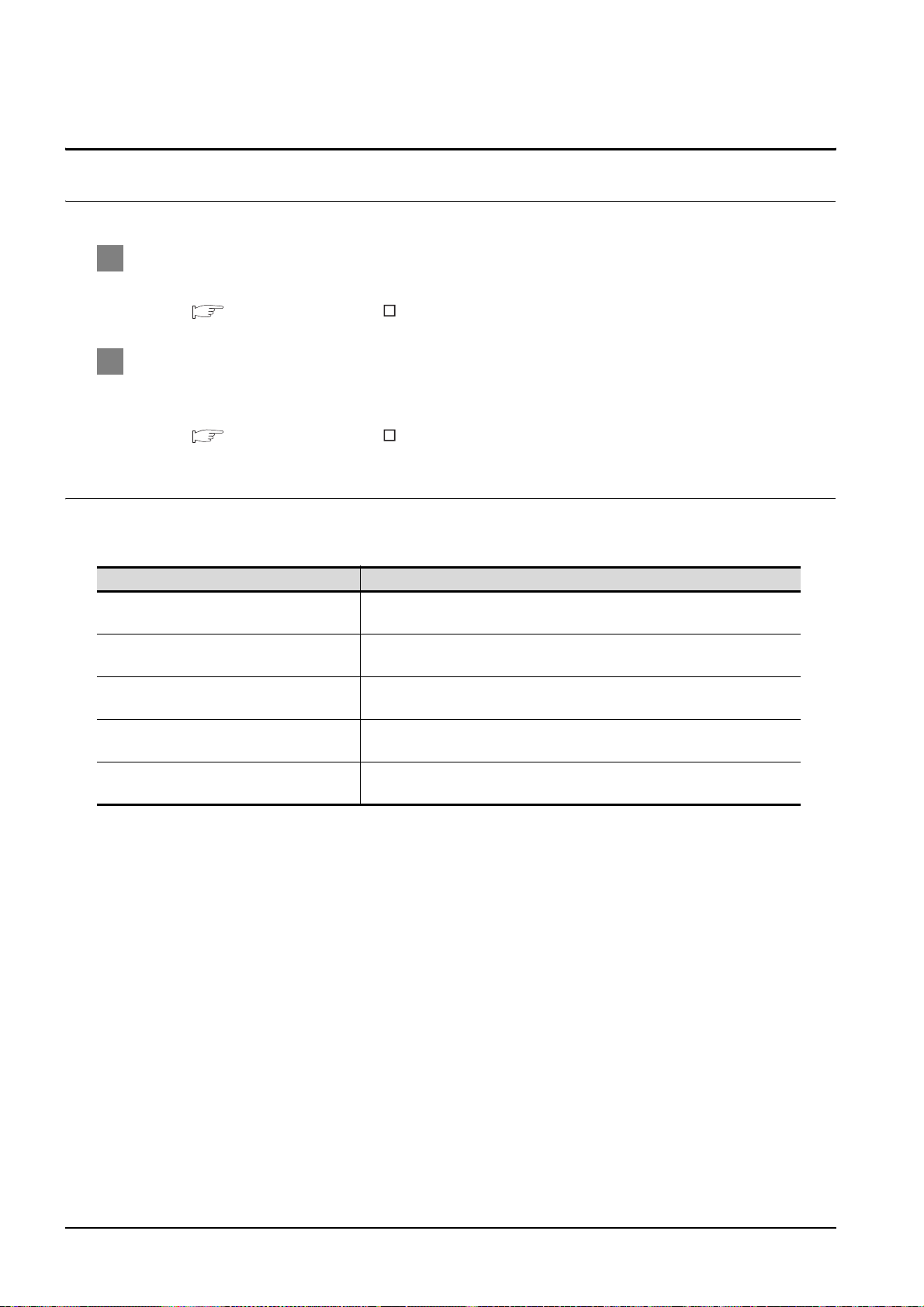
The following manuals are also related to this product.
In necessary, order them by quoting the details in the tables below.
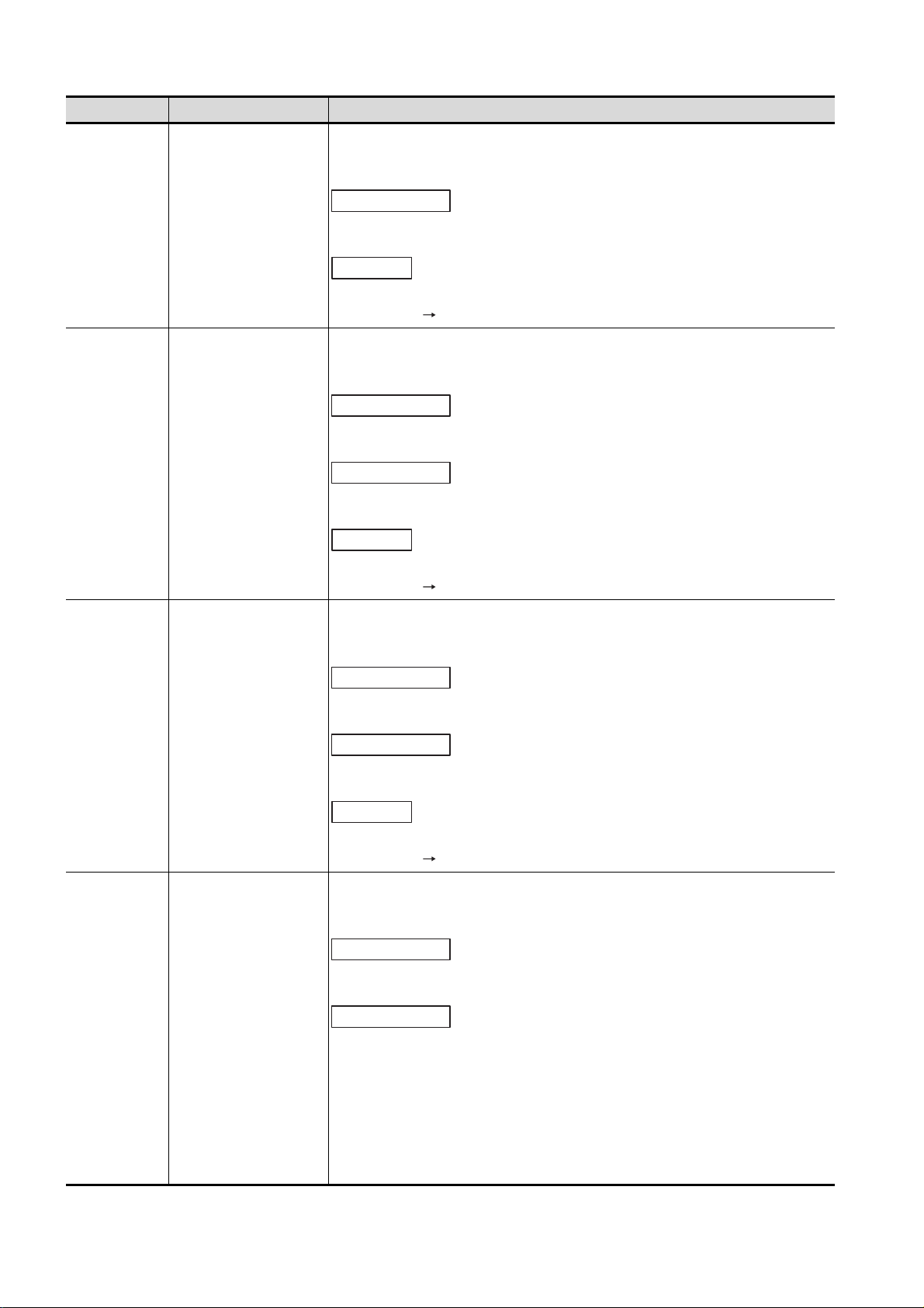
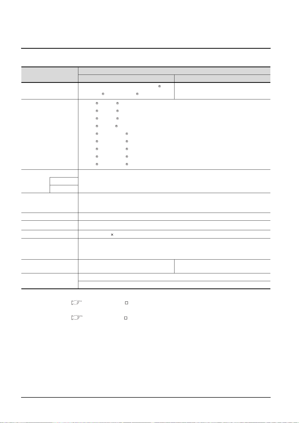
Related Manuals
Manual Name
GT16 User's Manual
- Describes the GT16 hardware-relevant contents, including the specifications, part names, mounting, power
supply wiring, external dimensions, and option devices.
- Describes the GT16 functions, including the utility.
(Sold separately)
GT Designer2 Version2 Basic Operation/Data Transfer Manual (For GOT1000 Series)
Describes methods of the GT Designer2 installation operation, basic operation for drawing and transmitting data
to GOT1000 series.
(Sold separately)*
GT Designer2 Version2 Screen Design Manual (For GOT1000 Series) 1/3
GT Designer2 Version2 Screen Design Manual (For GOT1000 Series) 2/3
GT Designer2 Version2 Screen Design Manual (For GOT1000 Series) 3/3
Describes specifications and settings of each object function applicable to GOT1000 series.
(Sold separately)*
GOT1000 Series Connection Manual 1/3
GOT1000 Series Connection Manual 2/3
GOT1000 Series Connection Manual 3/3
Describes system configurations of the connection method applicable to GOT1000 series and cable creation
method.
(Sold separately)*
GOT1000 Series Extended/Option Functions Manual
Describes extended functions and option functions applicable to GOT series.
(Sold separately)*
1
1
1
1
Manual Number
(Model Code)
SH-080778ENG
(1D7M88)
SH-080529ENG
(1D7M24)
SH-080530ENG
(1D7M25)
SH-080532ENG
(1D7M26)
SH-080544ENG
(1D7M32)
A - 10
*1 The manual in PDF-format is included in the GT Works2 and GT Designer2 products.
Page 13
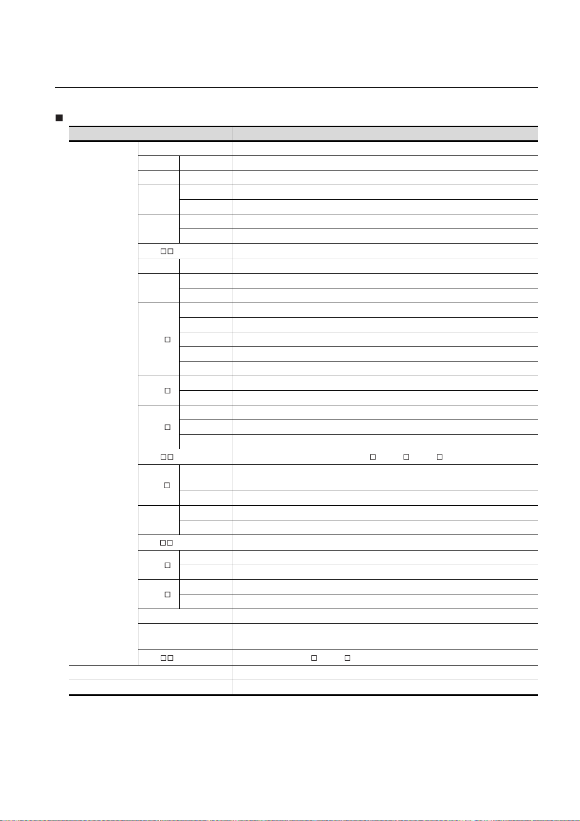
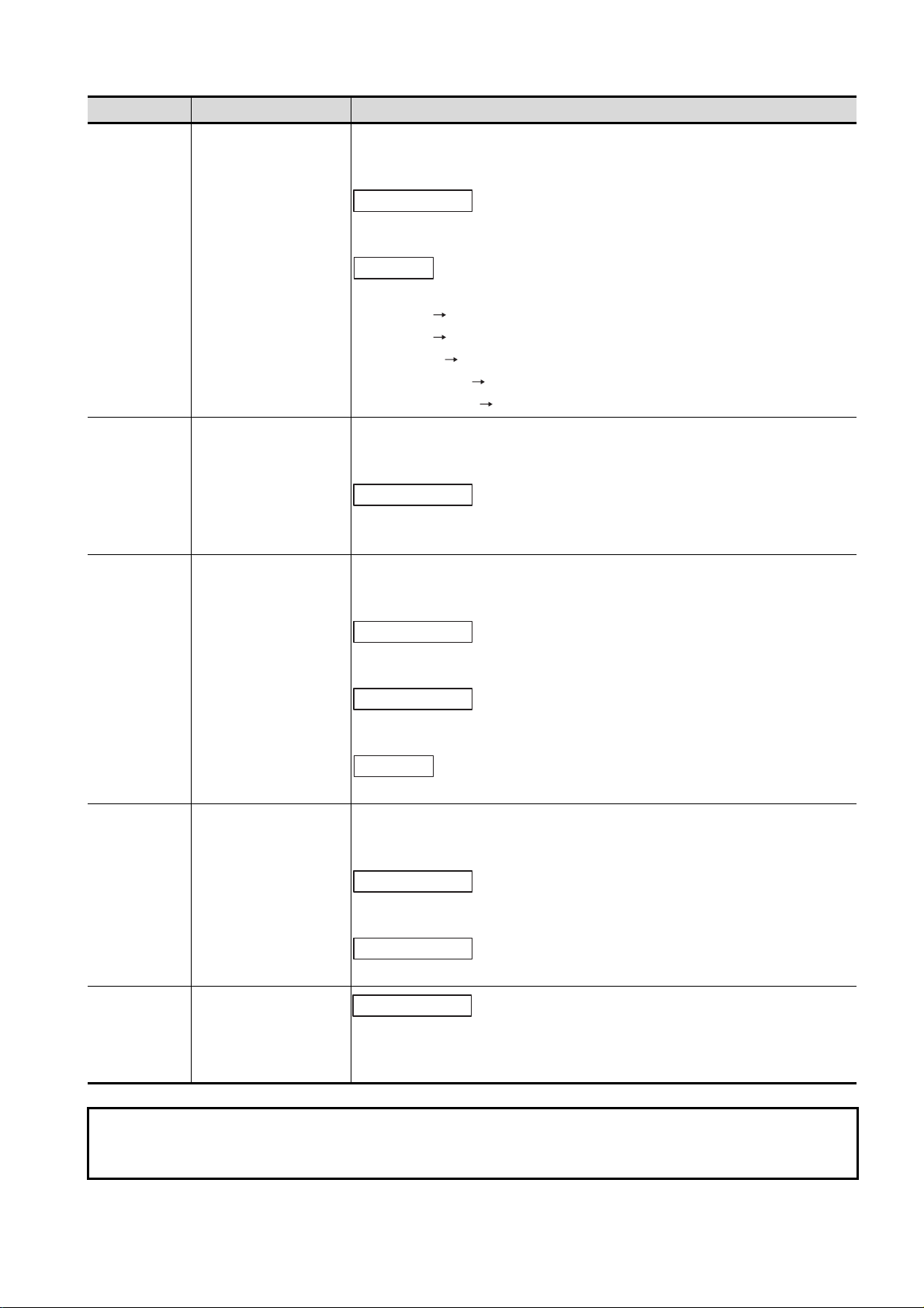
ABBREVIATIONS AND GENERIC TERMS
Abbreviations and generic terms used in this manual are as follows:
GOT
Abbreviations and generic terms Description
GT SoftGOT1000 Abbreviation of GT SoftGOT1000
GT1695 GT1695M-X Abbreviation of GT1695M-XTBA, GT1695M-XTBD
GT1685 GT1685M-S Abbreviation of GT1685M-STBA, GT1685M-STBD
GT1675
GT1665
GT16 , GT16
GT1595 GT1595-X Abbreviation of GT1595-XTBA, GT1595-XTBD
GT1585
GT157
GT156
GOT1000 Series
GT155
GT15 , GT15 Abbreviation of GT1595, GT1585, GT157 , GT156 , GT155
GT115
Handy
GOT
GT11 , GT11
GT105
GT104
GT1030 Abbreviation of GT1030-LBD, GT1030-LBD2, GT1030-LBDW, GT1030-LBDW2
GT1020
GT10 , GT10 Abbreviation of GT105 , GT104 , GT1030, GT1020
GOT900 Series Abbreviation of GOT-A900 series, GOT-F900 series
GOT800 Series Abbreviation of GOT-800 series
GT1675M-S Abbreviation of GT1675M-STBA, GT1675M-STBD
GT1675M-V Abbreviation of GT1675M-VTBA, GT1675M-VTBD
GT1665M-S Abbreviation of GT1665M-STBA, GT1665M-STBD
GT1665M-V Abbreviation of GT1665M-VTBA, GT1665M-VTBD
Abbreviation of GT1695,GT1685, GT1675, GT1665
GT1585V-S Abbreviation of GT1585V-STBA, GT1585V-STBD
GT1585-S Abbreviation of GT1585-STBA, GT1585-STBD
GT1575V-S Abbreviation of GT1575V-STBA, GT1575V-STBD
GT1575-S Abbreviation of GT1575-STBA, GT1575-STBD
GT1575-V Abbreviation of GT1575-VTBA, GT1575-VTBD
GT1575-VN Abbreviation of GT1575-VNBA, GT1575-VNBD
GT1572-VN Abbreviation of GT1572-VNBA, GT1572-VNBD
GT1565-V Abbreviation of GT1565-VTBA, GT1565-VTBD
GT1562-VN Abbreviation of GT1562-VNBA, GT1562-VNBD
GT1555-V Abbreviation of GT1555-VTBD
GT1555-Q Abbreviation of GT1555-QTBD, GT1555-QSBD
GT1550-Q Abbreviation of GT1550-QLBD
GT1155-Q
GT1150-Q Abbreviation of GT1150-QLBDQ, GT1150-QLBDA, GT1150-QLBD
GT1155HS-Q Abbreviation of GT1155HS-QSBD
GT1150HS-Q Abbreviation of GT1150HS-QLBD
GT1055-Q Abbreviation of GT1055-QSBD
GT1050-Q Abbreviation of GT1050-QBBD
GT1045-Q Abbreviation of GT1045-QSBD
GT1040-Q Abbreviation of GT1040-QBBD
Abbreviation of GT1155-QTBDQ, GT1155-QSBDQ, GT1155-QTBDA, GT1155-QSBDA,
GT1155-QTBD, GT1155-QSBD
Abbreviation of GT1155-Q, GT1150-Q, GT11 Handy GOT
Abbreviation of GT1020-LBD, GT1020-LBD2, GT1020-LBL, GT1020-LBDW,
GT1020-LBDW2, GT1020-LBLW
A - 11
Page 14

Communication unit
Abbreviations and generic terms Description
Bus connection unit
Serial communication unit GT15-RS2-9P, GT15-RS4-9S, GT15-RS4-TE
RS-422 conversion unit GT15-RS2T4-9P, GT15-RS2T4-25P
Ethernet communication unit GT15-J71E71-100
MELSECNET/H communication unit GT15-J71LP23-25, GT15-J71BR13
MELSECNET/10 communication unit
CC-Link IE controller network communication
unit
CC-Link communication unit
Interface converter unit GT15-75IF900
Serial multi-drop connection unit GT01-RS4-M
Connection Conversion Adapter GT10-9PT5S
GT15-QBUS, GT15-QBUS2, GT15-ABUS, GT15-ABUS2,
GT15-75QBUSL, GT15-75QBUS2L, GT15-75ABUSL, GT15-75ABUS2L
GT15-75J71LP23-Z*1, GT15-75J71BR13-Z
GT15-J71GP23-SX
GT15-J61BT13, GT15-75J61BT13-Z
*2
*3
*1 A9GT-QJ71LP23 + GT15-75IF900 set
*2 A9GT-QJ71BR13 + GT15-75IF900 set
*3 A8GT-J61BT13 + GT15-75IF900 set
Option unit
Abbreviations and generic terms Description
Printer unit GT15-PRN
Video input unit GT16M-V4, GT15V-75V4
Video/RGB unit
Multimedia unit GT16M-MMR
CF card unit GT15-CFCD
CF card extension unit
External I/O unit GT15-DIO, GT15-DIOR
Sound output unit GT15-SOUT
Fingerprint unit GT15-80FPA
RGB input unit GT16M-R2, GT15V-75R1
Video/RGB input unit GT16M-V4R1, GT15V-75V4R1
RGB output unit GT16M-ROUT, GT15V-75ROUT
*1
GT15-CFEX-C08SET
*1 GT15-CFEX + GT15-CFEXIF + GT15-C08CF set.
A - 12
Page 15

Option
Abbreviations and generic terms Description
Memory card CF card
Memory card adaptor GT05-MEM-ADPC
Option function board
Battery GT15-BAT, GT11-50BAT
Protective Sheet
Protective cover for oil
USB environmental protection cover GT16-UCOV, GT15-UCOV, GT11-50UCOV
Stan d
Attachment
Backlight
Multi-color display board GT15-XHNB, GT15-VHNB
Connector conversion box GT11H-CNB-37S
Emergency stop sw guard cover GT11H-50ESCOV
Memory loader GT10-LDR
Memory board GT10-50FMB
GT05-MEM-16MC, GT05-MEM-32MC, GT05-MEM-64MC, GT05-MEM-128MC,
GT05-MEM-256MC GT05-MEM-512MC, GT05-MEM-1GC, GT05-MEM-2GC
GT16-MESB, GT15-FNB, GT15-QFNB, GT15-QFNB16M,
GT15-QFNB32M, GT15-QFNB48M, GT15-MESB48M, GT11-50FNB
GT16-90PSCB, GT16-90PSGB, GT16-90PSCW, GT16-90PSGW,
For GT16
For GT15
For GT11
For GT10
GT05-90PCO, GT05-80PCO, GT05-70PCO, GT05-60PCO,
GT05-50PCO
GT15-90STAND, GT15-80STAND, GT15-70STAND, A9GT-50STAND,
GT05-50STAND
GT15-70ATT-98, GT15-70ATT-87, GT15-60ATT-97, GT15-60ATT-96,
GT15-60ATT-87, GT15-60ATT-77, GT15-50ATT-95W, GT15-50ATT-85
GT16-90XLTT, GT16-80SLTT, GT15-90XLTT, GT15-80SLTT,
GT16-70SLTT, GT16-70VLTT, GT16-60SLTT, GT16-60VLTT,
GT15-70SLTT, GT15-70VLTT, GT15-70VLTN, GT15-60VLTT,
GT15-60VLTN
GT16-80PSCB, GT16-80PSGB, GT16-80PSCW, GT16-80PSGW,
GT16-70PSCB, GT16-70PSGB, GT16-70PSCW, GT16-70PSGW,
GT16-60PSCB, GT16-60PSGB, GT16-60PSCW, GT16-60PSGW
GT15-90PSCB, GT15-90PSGB, GT15-90PSCW, GT15-90PSGW,
GT15-80PSCB, GT15-80PSGB, GT15-80PSCW, GT15-80PSGW,
GT15-70PSCB, GT15-70PSGB, GT15-70PSCW, GT15-70PSGW,
GT15-60PSCB, GT15-60PSGB, GT15-60PSCW, GT15-60PSGW,
GT15-50PSCB, GT15-50PSGB, GT15-50PSCW, GT15-50PSGW
GT11-50PSCB, GT11-50PSGB, GT11-50PSCW, GT11-50PSGW,
GT11H-50PSC
GT10-50PSCB, GT10-50PSGB, GT10-50PSCW, GT10-50PSGW,
GT10-40PSCB, GT10-40PSGB, GT10-40PSCW, GT10-40PSGW,
GT10-30PSCB, GT10-30PSGB, GT10-30PSCW, GT10-30PSGW,
GT10-20PSCB, GT10-20PSGB, GT10-20PSCW, GT10-20PSGW
Software
Abbreviations and generic terms Description
GT Works2 Version SW D5C-GTWK2-E, SW D5C-GTWK2-EV
GT Designer2 Version SW D5C-GTD2-E, SW D5C-GTD2-EV
GT Designer2 Abbreviation of screen drawing software GT Designer2 for GOT1000/GOT900 series
GT Converter2 Abbreviation of data conversion software GT Converter2 for GOT1000/GOT900 series
GT Simulator2 Abbreviation of screen simulator GT Simulator 2 for GOT1000 / GOT900 series
GT SoftGOT1000 Abbreviation of monitoring software GT SoftGOT1000
GT SoftGOT2 Abbreviation of monitoring software GT SoftGOT2
GX Developer
GX Simulator
Document Converter Abbreviation of document data conversion software Document Converter for GOT1000 series
PX Developer
Abbreviation of SW D5C-GPPW-E(-EV)/SW D5F-GPPW-E type software package
Abbreviation of SW D5C-LLT-E(-EV) type ladder logic test tool function software packages
(SW5D5C-LLT (-EV) or later versions)
Abbreviation of SW D5C-FBDQ-E type FBD software package for process control
A - 13
Page 16

License key (for GT SoftGOT1000)
Abbreviations and generic terms Description
License GT15-SGTKEY-U, GT15-SGTKEY-P
License key (for GT SoftGOT2)
Abbreviations and generic terms Description
License key A9GTSOFT-LKEY-P (For DOS/V PC)
License key FD SW5D5F-SGLKEY-J (For PC CPU module)
Others
Abbreviations and generic terms Description
OMRON PLC Abbreviation of PLC manufactured by OMRON Corporation
KEYENCE PLC Abbreviation of PLC manufactured by KEYENCE CORPORATION
KOYO EI PLC Abbreviation of PLC manufactured by KOYO ELECTRONICS INDUSTRIES CO., LTD.
SHARP PLC Abbreviation of PLC manufactured by Sharp Manufacturing Systems Corporation
JTEKT PLC Abbreviation of PLC manufactured by JTEKT Corporation
TOSHIBA PLC Abbreviation of PLC manufactured by TOSHIBA CORPORATION
TOSHIBA MACHINE PLC Abbreviation of PLC manufactured by TOSHIBA MACHINE CO., LTD.
HITACHI IES PLC Abbreviation of PLC manufactured by Hitachi Industrial Equipment Systems Co., Ltd.
HITACHI PLC Abbreviation of PLC manufactured by Hitachi, Ltd.
FUJI FA PLC Abbreviation of PLC manufactured by Fuji Electric FA Components & Systems Co., Ltd.
PANASONIC PLC Abbreviation of PLC manufactured by Panasonic Electric Works Co., Ltd.
YASKAWA PLC Abbreviation of PLC manufactured by YASKAWA Electric Corporation
YOKOGAWA PLC Abbreviation of PLC manufactured by Yokogawa Electric Corporation
ALLEN-BRADLEY PLC Abbreviation of Allen-Bradley PLC manufactured by Rockwell Automation, Inc.
GE FANUC PLC Abbreviation of PLC manufactured by GE Fanuc Automation Corporation
LS IS PLC Abbreviation of PLC manufactured by LS Industrial Systems Co., Ltd.
SCHNEIDER PLC Abbreviation of PLC manufactured by Schneider Electric SA
SIEMENS PLC Abbreviation of PLC manufactured by Siemens AG
OMRON temperature
controller
SHINKO indicating
controller
CHINO controller Abbreviation of temperature controller manufactured by CHINO CORPORATION
Temperature
controller
PC CPU module Abbreviation of PC CPU Unit manufactured by CONTEC CO., LTD
GOT (server) Abbreviation of GOTs that use the server function
GOT (client) Abbreviation of GOTs that use the client function
FUJI SYS temperature
controller
YAMATAKE temperature
controller
YOKOGAWA temperature
controller
RKC temperature
controller
Abbreviation of temperature controller manufactured by OMRON Corporation
Abbreviation of temperature controller manufactured by Shinko Technos Co., Ltd.
Abbreviation of temperature controller manufactured by Fuji Electric Systems Co., Ltd.
Abbreviation of temperature controller manufactured by Yamatake Corporation
Abbreviation of temperature controller manufactured by Yokogawa Electric Corporation
Abbreviation of temperature controller manufactured by RKC INSTRUMENT INC.
Windows font
Intelligent function module
MODBUS /TCP
A - 14
Abbreviation of TrueType font and OpenType font available for Windows
(Differs from the True Type fonts settable with GT Designer2)
Indicates the modules other than the PLC CPU, power supply module and I/O module that are
mounted to the base unit.
Generic term for the protocol designed to use MODBUS protocol messages on a TCP/IP
network.
Page 17
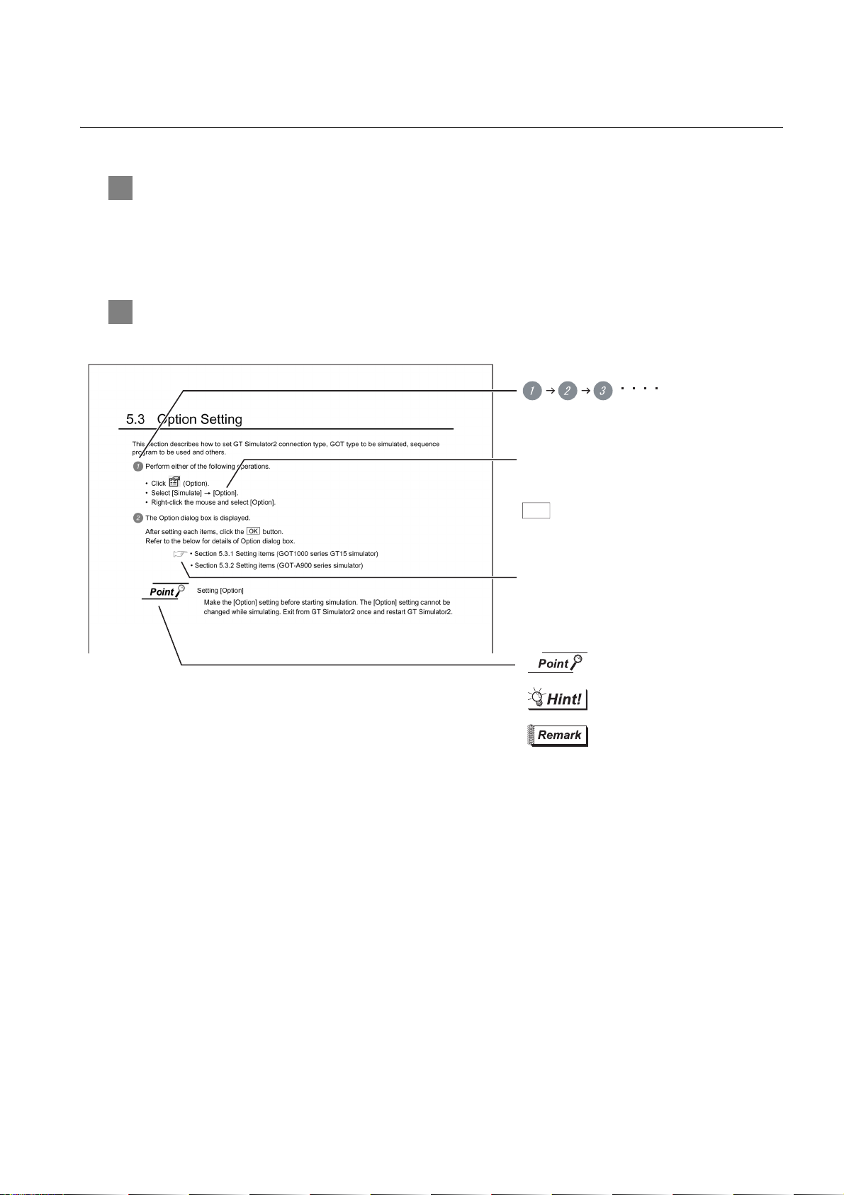
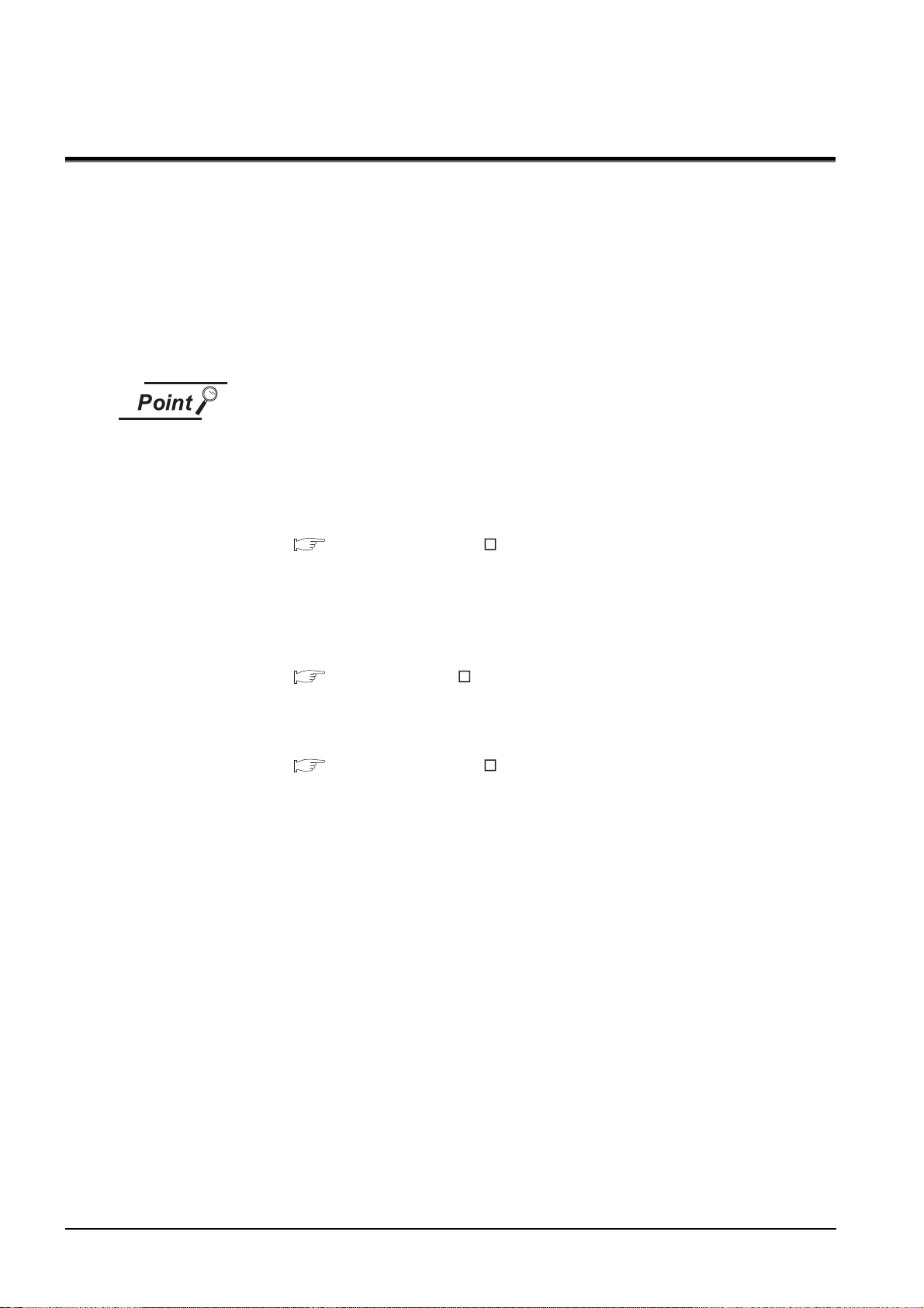
HOW TO READ THIS MANUAL
indicates the operation steps.
Refers to information required
for operation.
Refers to information useful
for operation.
Refers to supplementary
explanations for reference.
Indicates the location in which the detailed
explanation is given (manual, chapter section,
item of the manual).
Menu and items are differentiated with
parentheses.
[ ] refers to the menu of GOT utility.
: refers to dialog box buttons or keys
of PC keyboard.
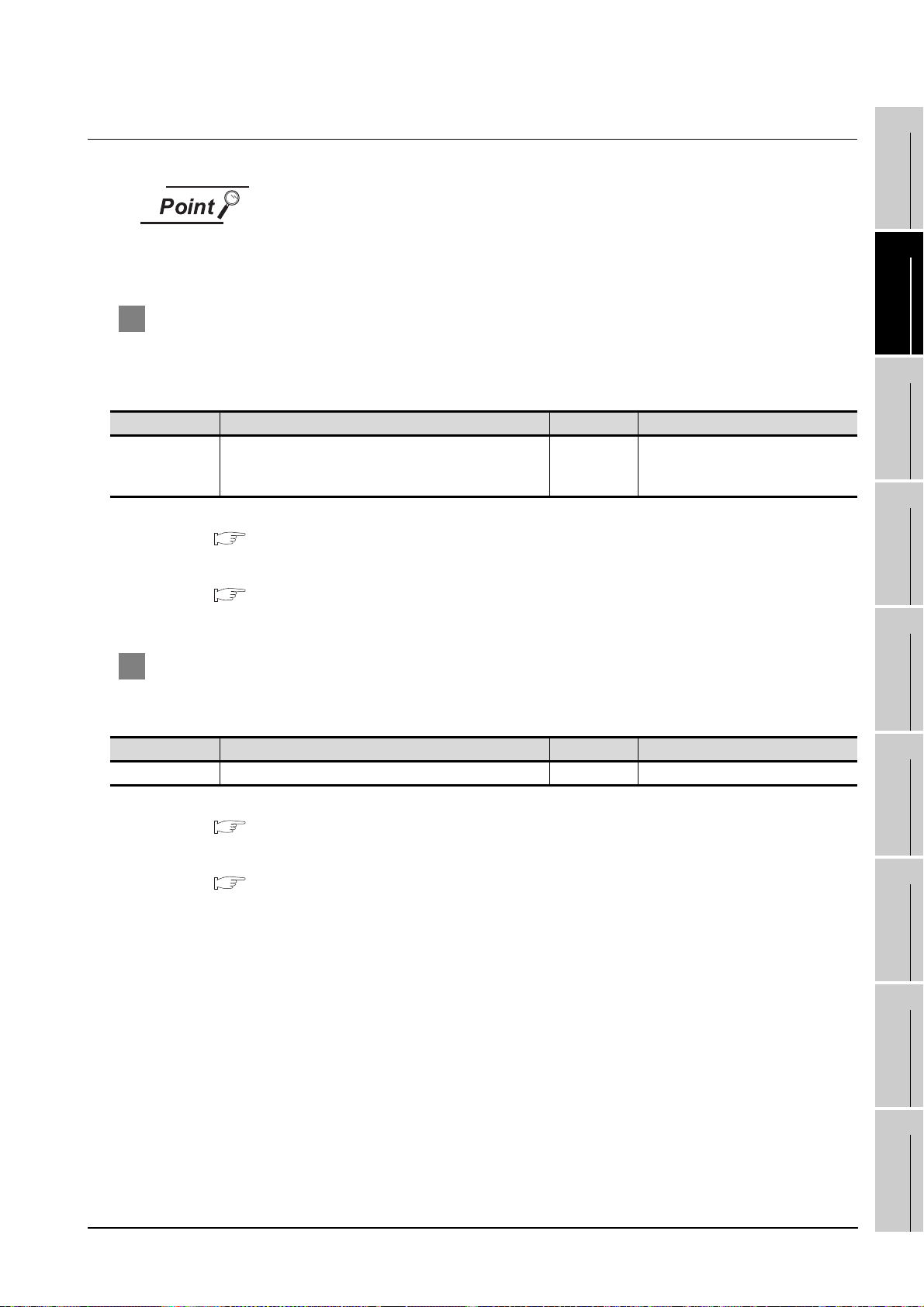
1 Functions
This manual describes functions available for the GT SoftGOT1000 Version2.96A.
For the added functions by the product version upgrade, refer to the list of functions added by GT
SoftGOT1000 version upgrade in Appendices.
2 Symbols
Following symbols are used in this manual.
*Since the above page was created for explanation purpose, it differs from the actual page.L
A - 15
Page 18
1. OVERVIEW
This manual explains the system configuration, specifications, screen structure, and operating method of
monitoring software GT SoftGOT1000 (hereinafter abbreviated as GT SoftGOT1000).
GT SoftGOT1000 is the software that has the same functions as the GOT1000 series and is used to display
lamps, data, and messages on personal computers and panel controllers.
When applying the following program examples to the actual system, make sure to examine the applicability
and confirm that it will not cause system control problems.
Described contents in this manual
This manual describes the operation method for GT SoftGOT1000.
For other than operation method, refer to the following manuals.
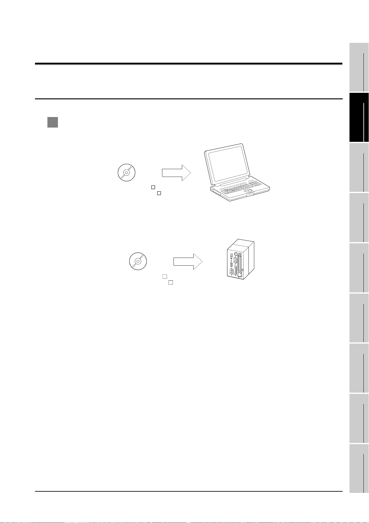
(1) Installation method of GT SoftGOT1000
For the installation method of GT SoftGOT1000, refer to the following manuals.
GT Designer2 Version Basic Operation/Data Transfer Manual
(2.2 Installing the Software Programs)
(2) Project data creating method of GT Designer2
For the project data creating method of GT Designer2, refer to the following
manuals.
Designer2 Version Screen Design Manual
(3) Starting method of GT SoftGOT1000
For the starting method of GT SoftGOT1000, refer to the following manual.
GT Designer2 Version Basic Operation/Data Transfer Manual
(2.4 Starting the Software)
1 - 1
Page 19
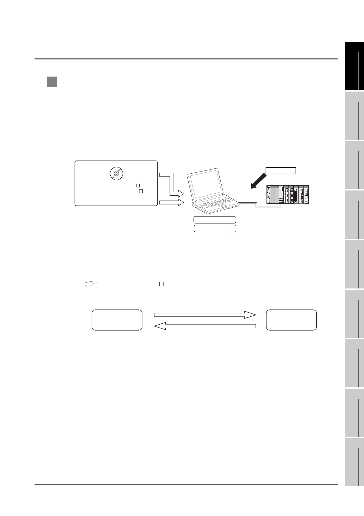
1.1 Features
Install
GT SoftGOT1000
GX Developer
GT Works2 Version
GT Designer2 Version
(GT Designer2, GT SoftGOT1000)
License key
CPU direct
connection
Attach
PX Developer
GT SoftGOT1000
Call a monitor tool function for in PX Developer
on GT SoftGOT1000.
Register GT SoftGOT1000 as a user graphic
screen of PX Developer, and start the registered
GT SoftGOT1000.
1
1 The features of the GOT series and advantages of personal computer and panel
computer are available
(1) Interactive use with applications (including MELSOFT)
(a) Interactive use with GT Designer2.
Installation of GT SoftGOT1000 and GT Designer2 on the same personal computer allows
operations from screen creation to monitoring to be supported by a single personal computer.
Immediately after creating or modifying a screen on GT Designer2, the screen can be
monitored on GT SoftGOT1000. Therefore, design efficiency is improved greatly.
(b) Interaction with PX Developer
With interaction between GT SoftGOT1000 and PX Developer, monitor tool functions for PX
Developer can be called on GT SoftGOT1000.
GT SoftGOT1000 can also be started on PX Developer, and the functions can be shared.
For the monitor tool of PX Developer, refer to the following manual.
PX Developer Version Operating Manual (Monitor Tool)
OVERVIEW
2
SYSTEM
CONFIGURATION
3
SPECIFICATIONS
4
SCREEN
CONFIGURATION
5
OPERATING
METHOD
1.1 Features
6
FUNCTIONS
7
INTERNAL DEVICE
INTERFACE
FUNCTION
8
TROUBLESHOOTING
APPENDICES
1 - 2
Page 20
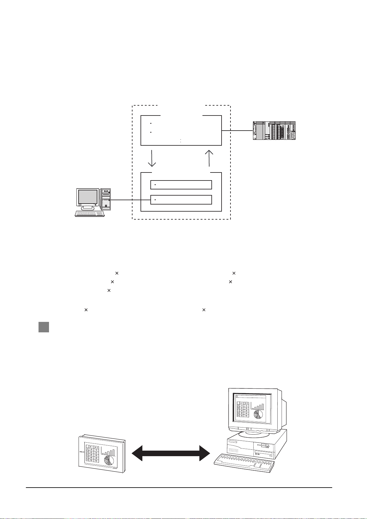
(c) Interactive use with Windows applications
Personal computer
GT SoftGOT1000
User-created application
PLC
Communication with PLC
Screen display (alarm etc.)
User's own data control
Server
Reading/writing
internal device value
User's own control
GOT GT SoftGOT1000
The monitor screen data is compatible.
A Windows application can be started up from GT SoftGOT1000.
Also, the data of GT SoftGOT1000 internal devices can be read/written from a user-created
application.
With interaction between GT SoftGOT1000 and a user-created application, the user can
control or manage data by own method.
(2) Flexible response to high-resolution
The user can select resolutions from UXGA to VGA and can set a resolution specification, which
sets a resolution dot by dot depending on applications.
GT SoftGOT1000 supports the following resolutions.
(a) Selectable resolutions
•UXGA (1600 1200 dots) • SXGA (1280 1024 dots)
•XGA (1024 768 dots) • SVGA (800 600 dots)
•VGA (640 480 dots)
(b) User setting
•X Y (Resolution specification) (1920 to 640 1200 to 480 dots)
2 The monitor screen data created for the GOT1000 series is applicable to GT
SoftGOT1000.
The GT SoftGOT1000 uses monitor screen data created with GT Designer2.
By converting the GOT type for GT SoftGOT1000, the monitor screen data used for the GOT1000
series can be used without modification.
GT SoftGOT1000 uses the same screens and operations as GOT.
Therefore, there will be no discomfort or confusion for the operators and maintenance personnel.
1 - 3
1.1 Features
Page 21
2. SYSTEM CONFIGURATION
DOS/V personal computer
GT Works2 Version
GT Designer2 Version
PC CPU module
GT Works2 Version
GT Designer2 Version
1
2.1 System Configuration
1 When installing GT SoftGOT1000
(1) When installing GT SoftGOT1000 on DOS/V personal computer
(2) When installing GT SoftGOT1000 on PC CPU module
OVERVIEW
2
SYSTEM
CONFIGURATION
3
SPECIFICATIONS
4
SCREEN
CONFIGURATION
5
INTERNAL DEVICE
OPERATING
6
7
INTERFACE
8
METHOD
FUNCTIONS
FUNCTION
TROUBLESHOOTING
2.1 System Configuration
APPENDICES
2 - 1
Page 22
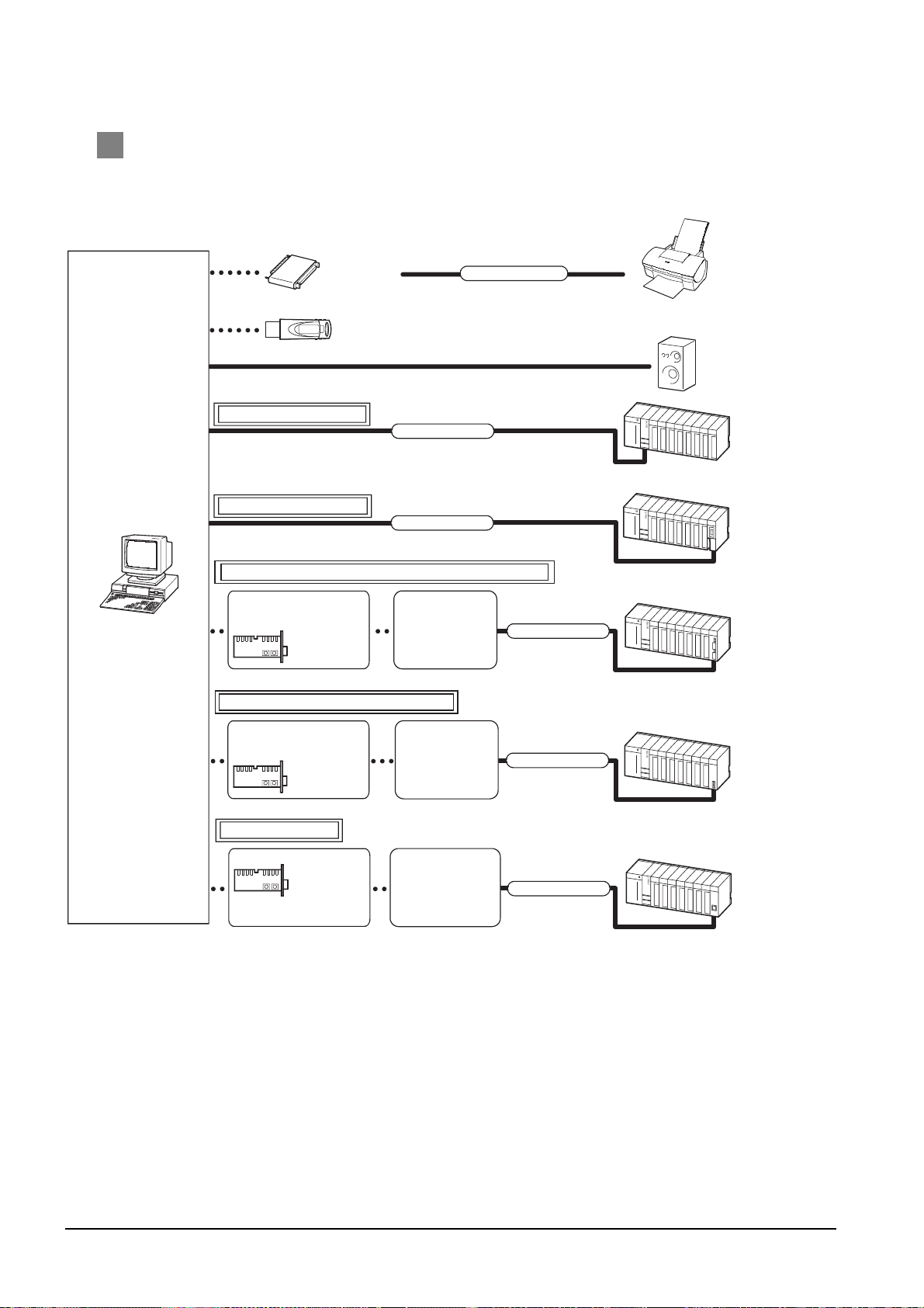
2 When executing GT SoftGOT1000
Direct connection to CPU
Printer cable
License key
(GT15-SGTKEY-P)
Printer
Sound output
device
Connection cable
PLC CPU
Ethernet connection
DOS/V personal computer
Ethernet
module
Computer link connection
Computer link
module, Serial
communication
module
Driver
MELSECNET/H connection, MELSECNET/10 connection
MELSECNET/H
network module,
MELSECNET/10
network module
MELSECNET/H board
Driver
Ethernet board
Driver supplied with
MELSECNET/H
board
Commercially available
Ethernet board
Driver supplied with
commercially available
Ethernet board
License key (GT15-SGTKEY-U)
Connection cable
Connection cable
Connection cable
CC-Link IE controller network connection
CC-Link IE
controller
network module
CC-Link IE controller
network interface board
Driver supplied with
CC-Link IE
controller network
interface board
Driver
Connection cable
(1) When using GT SoftGOT1000 on DOS/V personal computer
2 - 2
2.1 System Configuration
Page 23
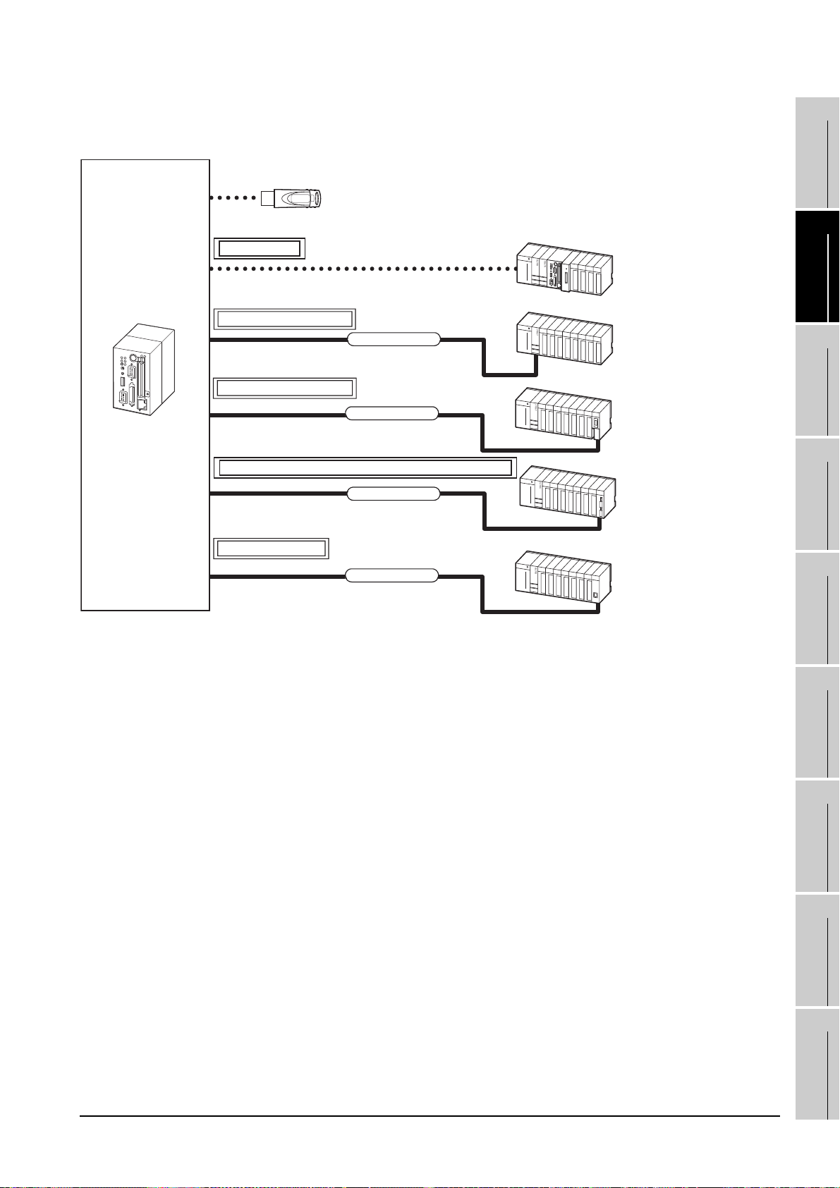
(2) When using GT SoftGOT1000 with PC CPU module
1
GT SoftGOT1000
PC CPU module
License key (GT15-SGTKEY-U)
Bus connection
Direct connection to CPU
Connection cable
Computer link connection
Connection cable
MELSECNET/H connection, MELSECNET/10 connection
Connection cable
Ethernet connection
Connection cable
PLC CPU on the main
base unit that the PC CPU
module exists
PLC CPU on the main
base unit that the PC CPU
module does not exist
Computer link module, serial
communication module on
the main base unit that
the PC CPU module
does not exist
MELSECNET/H network
module, MELSECNET/10
network module on the main
base unit that the PC CPU
module does not exist
Ethernet module on the
main base unit that the PC CPU
module does not exist
OVERVIEW
2
SYSTEM
CONFIGURATION
3
SPECIFICATIONS
4
SCREEN
CONFIGURATION
5
INTERNAL DEVICE
OPERATING
6
7
INTERFACE
8
METHOD
FUNCTIONS
FUNCTION
TROUBLESHOOTING
2.1 System Configuration
APPENDICES
2 - 3
Page 24
2.2 Operating Environment
The following shows the GT SoftGOT1000 operating environment.
Item
Personal computer
Operating system
Computer
Memory
Hard disk space*1
Disk drive CD-ROM drive
PC/AT compatible PC on which Windows 2000 ,
Windows XP or Windows Vista operates.
Microsoft Windows 2000 Professional Operating System Service Pack 4 or later [English version]
Microsoft Windows XP Professional Operating System Service Pack 2 or later [English version]
Microsoft Windows XP Home Edition Operating System Service Pack 2 or later [English version]
Microsoft Windows XP Embedded [English version]
Microsoft Windows Vista Ultimate Operating System [English version]
Microsoft Windows Vista Enterprise Operating System [English version]
Microsoft Windows Vista Business Operating System [English version]
Microsoft Windows Vista Home Premium Operating System [English version]
Microsoft Windows Vista Home Basic Operating System [English version]
Refer to "Applicable operating system and performance required for personal computer" on the next page.CPU
For installation (This product only) :600MB or more
For installation (This product and manuals) :850MB or more
For execution :100MB or more
With DOS/V personal computer With PC CPU module
Description
PPC-852-21B, PPC-852-21G, and PPC-852-22F
manufactured by CONTEC CO., LTD
*3*4*8
*3*4*9
*3*4*9
*3*4*9
*3*4*9
*3*4*9
*7
*2
*3*4*9
*3*4*9
Display color
Display
Software
Hardware*6
Others
65536 colors or more
Resolution of 640 480 dots or more
When creating or editing project data: GT Designer2
When using with PX Developer : PX Developer Version 1.14Q or later
GT Designer2 Version 2.47Z or later
GT15-SGTKEY-U (License key (for USB port) )
GT15-SGTKEY-P (License key (for parallel port) )
Installation of Internet Explorer 5.0 or later
The mouse, keyboard, printer, CD-ROM drive, sound card, and speakers must be compatible with the above OS.
*5
GT15-SGTKEY-U (License key (for USB port) )
*1 When using GT Designer2 or PX Developer, free space is required separately.
For the free space required when using GT Designer2, refer to the following manual.
GT Designer2 Version Basic Operation/Data Transfer Manual
For the available space required when using monitor tool functions of PX Developer, refer to the following
manual.
PX Developer Version Operating Manual (Monitor Tool)
When using a user-created application, free space is required separately.
*2 Administrator authority is required for installing GT SoftGOT1000.
*3 Administrator authority is required for installing and using GT SoftGOT1000.
*4 The following functions are not supported.
• "Compatibility mode" • "Fast user switching"
• "Change your desktop themes (fonts)" • "Remote desktop"
*5 Use GT Designer2 included in GT Works2/GT Designer2 that contains GT SoftGOT1000.
*6 When using GT15-SGTKEY-U, a USB port is required in the personal computer.
When using GT15-SGTKEY-P, a parallel port (Centronics/printer connecter) is required in the personal computer.
*7 Refer to the manual of the PC CPU module.
*8 For using the PPC-852-22F, GT SoftGOT1000 can be used on the PPC-852-22F with the OS preinstalled only.
*9 Only the 32-bit OS is available.
2 - 4
2.2 Operating Environment
Page 25

Applicable operating system and performance required for personal computer
1
Operating system
Microsoft Windows 2000 Professional Operating System [English version]
Microsoft Windows XP Professional Operating System [English version]
Microsoft Windows XP Home Edition Operating System [English version]
Microsoft Windows Vista Ultimate Operating System [English version]
Microsoft Windows Vista Enterprise Operating System [English version]
Microsoft Windows Vista Business Operating System [English version]
Microsoft Windows Vista Home Premium Operating System [English version]
Microsoft Windows Vista Home Basic Operating System [English version]
Operating environment when using a user-created application
A user-created application is used with GT SoftGOT1000.
When using a user-created application, therefore, prepare an operating environment
where both the user-created application and GT SoftGOT1000 can operate.
Performance required for personal computer
CPU Memory
Pentium 300MHz or
more
Pentium 300MHz or
more
800MHz or more
(Recommended: 1GHz or
more)
128MB or more
128MB or more
512MB or more
(Recommended: 1GB or
more)
OVERVIEW
2
SYSTEM
CONFIGURATION
3
SPECIFICATIONS
4
SCREEN
CONFIGURATION
INTERNAL DEVICE
5
OPERATING
6
7
INTERFACE
8
METHOD
FUNCTIONS
FUNCTION
2.2 Operating Environment
TROUBLESHOOTING
APPENDICES
2 - 5
Page 26
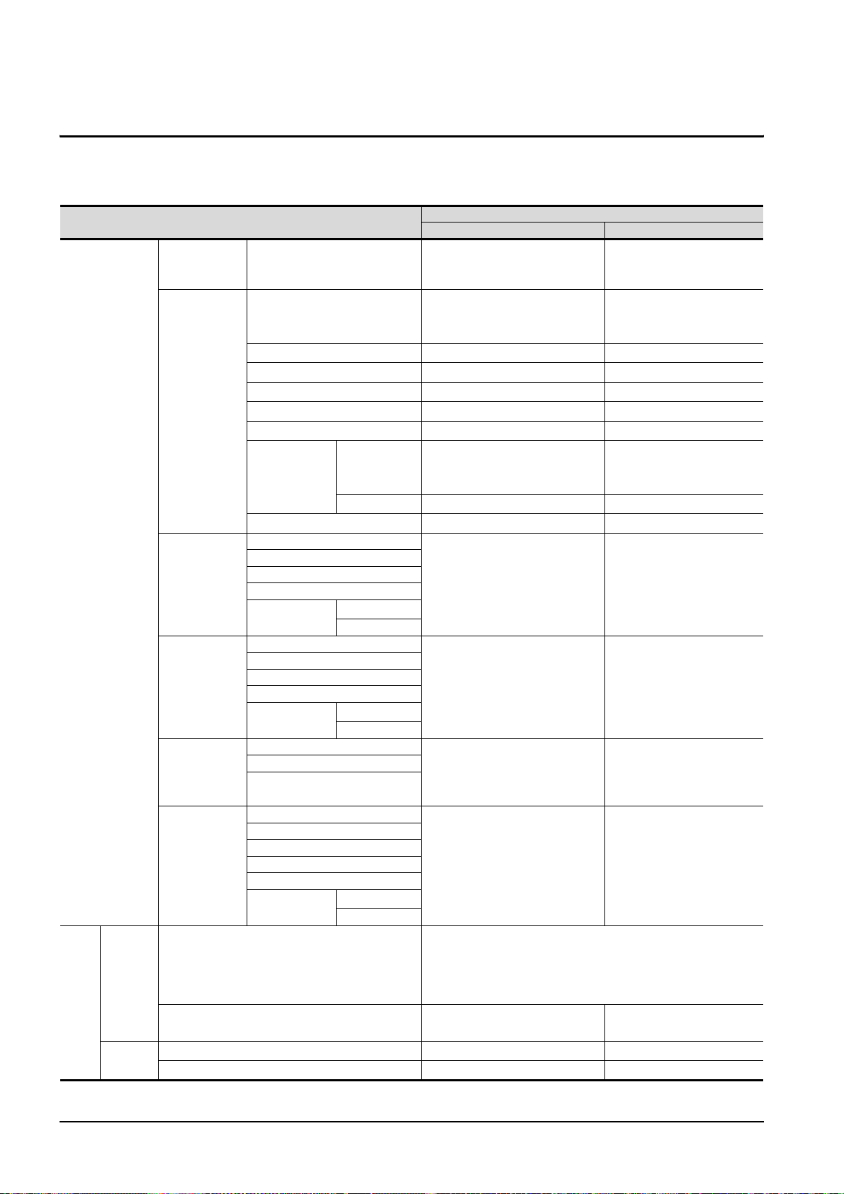
2.3 Connection conditions
The following table shows the connection distance between a controller and a personal computer and the
number of connectable personal computers when connecting GT SoftGOT1000 and a controller.
MITSUBISHI PLC
CNC C70
CNC
MELDAS
C6/C64
Connection type
Bus
connection
*8
QCPU (Q mode)
QCPU (Q mode)
Distance between controller and PC Number of connectable PCs
Connecting to the PLC CPU on the
main base unit that the PC CPU
module exists
RS-232 connection: 3m
USB connection: 3m
Connection conditions
QCPU (A mode) 15m
QSCPU 3m
Direct CPU
connection
QnACPU 15m
ACPU 15m
FXCPU 4.5m
Motion
controller CPU
Q series
*9
RS-232 connection: 3m
USB connection: 3m
A series 15m
MELSECNET/H remote I/O station 3m
QCPU (Q mode)
QCPU (A mode)
Computer link
connection
QnACPU
ACPU
Motion
controller CPU
Q series
A series
15m
*9
QCPU
MELSECNET/H
connection,
MELSECNET/
10 connection
CC-Link IE
controller
network
connection
QSCPU
QnACPU
ACPU
Motion
controller CPU
Q series
A series
*9
QCPU (Q mode)
QSCPU
Motion controller CPU (Q series)
Optical fiber cable: 1km
Coaxial cable: 500m
*7
550m
*9
*5
*5
QCPU (Q mode)
QCPU (A mode)
Ethernet
connection
QSCPU
QnACPU
ACPU
Motion
controller CPU
Q series
A series
100m (max. segment length)
*9
Direct CPU connection*2, Computer link connection*2,
MELSECNET/H connection*2, MELSECNET/10
Same as QCPU(Q mode)
connection*2, CC-Link IE controller network
connection
*2
Display I/F connection 100m (max. segment length)
Direct CPU connection 15m
Ethernet connection 100m (max. segment length)
*1
1
1 (2 units are connectable
when using both RS-232 and
USB connections.)
*1
1
*1
1
*1
1
*1
1
*1
1
*1
1 (2 units are connectable
when using both RS-232 and
USB connections.)
*1
1
*1
1
*1
1
Optical fiber cable: 64
Coaxial cable: 32
*1
120
*1
*1*6
*1*6
128 (recommended to 16 units
*1
or less)
128 (recommended to 16 units
*1
or less)
*1
1
*1
128
(Continued to next page)
2 - 6
2.3 Connection conditions
Page 27
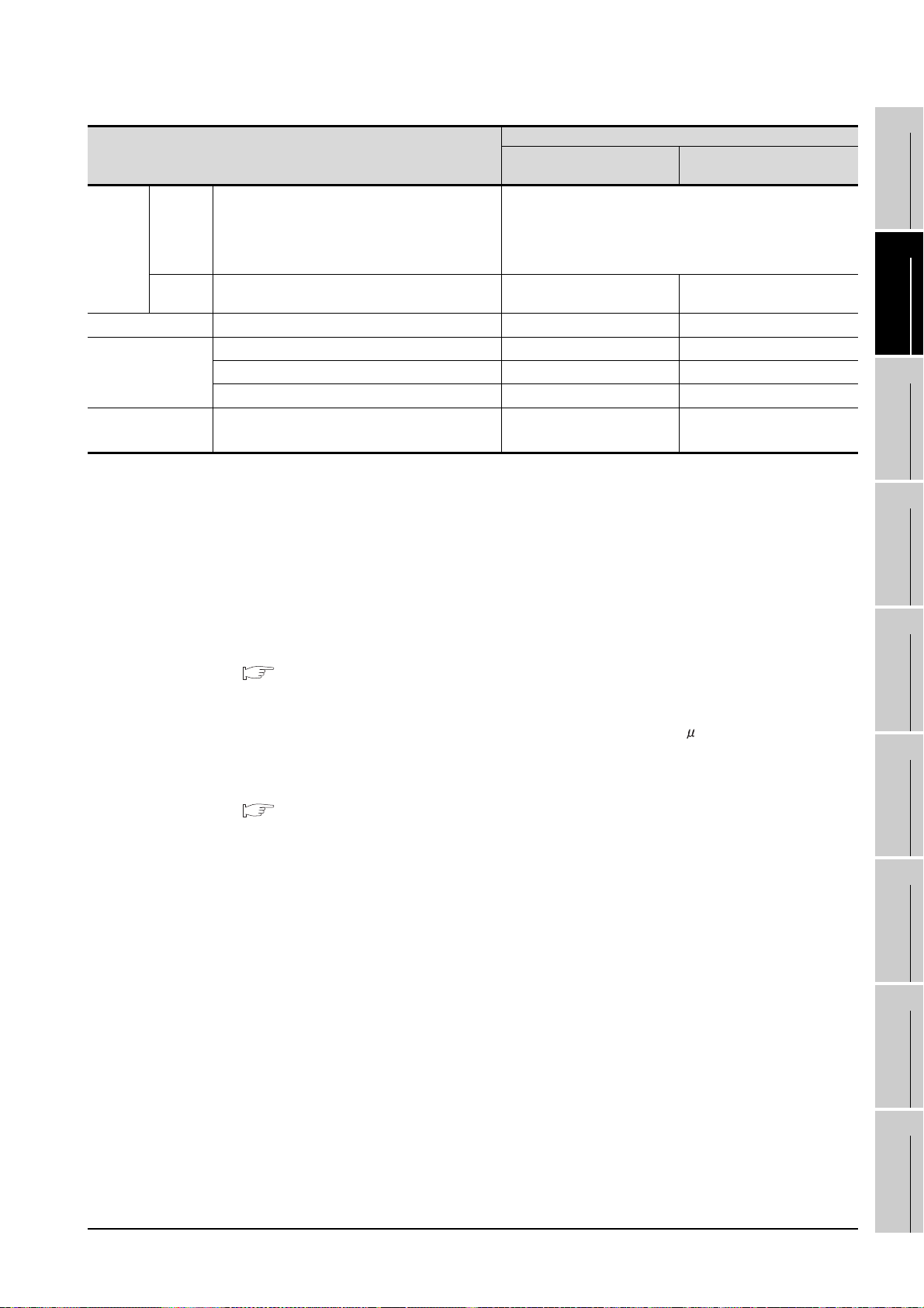
Connection conditions
Connection type
Direct CPU connection*2, Computer link connection*2,
CRnQ-
Robot
controller
OMRON PLC Direct CPU connection 15m
YASKAWA PLC
YOKOGAWA PLC Ethernet connection 100m (max. segment length)
700
CRnD-
700
MELSECNET/H connection*2, MELSECNET/10
connection*2, CC-Link IE controller network
connection*2, Ethernet connection
Ethernet connection 100m (max. segment length) 1
Direct CPU connection 15m
Computer link connection 15m
Ethernet connection 100m (max. segment length)
*1 When starting up multiple GT SoftGOT1000 modules, monitoring is enabled on the multiple screens.
*2 The multiple CPU system with the QCPU (Q mode) is mounted on.
*3 To use GT SoftGOT1000 module together with another GT SoftGOT1000 module or a different application, set
the different number for each port No.
If the port No. is the same, monitoring may not be available due to a communication timeout, or other causes.
*4 The number of connectable personal computers includes the number of total GT SoftGOT 1000 modules started
in a personal computer.
*5 Distance between stations for using QSI optical cable and 5C-2V coaxial cable.
The overall distance and distance between stations differs according to the type and the number of total stations
for the cable to be used.
For details on the cable, refer to the following manual.
Q Corresponding MELSECNET/H Network System Reference Manual (PLC to PLC network)
*6 Applicable when using one MELSECNET/H board per personal computer.
Up to four MELSECNET/H boards can be mounted per personal computer.
*7 Distance between stations for using the fiber-optic cable (core/cladding = 50/125( m)
The overall distance and distance between stations differs according to the type and the number of total stations
for the cable to be used.
For details on the cable, refer to the following manual.
CC-Link IE Controller Network Reference Manual
*8 The connection type can be used only with the PC CPU module.
*9 For the motion controller CPU (Q series), only the PLC CPU area (CPU No.1) in the Q170MCPU can be
monitored. The PERIPHERAL I/F is unavailable for connecting the GOT.
*2
Distance between controller and
PC
Same as QCPU(Q mode)
Number of connectable PCs
*1
1
*1
1
*1
1
*3*4
10
UDP: 128
TCP: 8
*3
*3*4
1
OVERVIEW
2
SYSTEM
CONFIGURATION
3
SPECIFICATIONS
4
SCREEN
CONFIGURATION
5
OPERATING
METHOD
6
FUNCTIONS
7
2.3 Connection conditions
INTERNAL DEVICE
INTERFACE
FUNCTION
8
TROUBLESHOOTING
APPENDICES
2 - 7
Page 28
2.4 Connectable Modules
2.4.1 MITSUBISHI PLC
1 Applicable CPU
Refer to the following manual for PLC CPUs that can be monitored from GT SoftGOT1000.
GT Designer2 Version Screen Design Manual
2 Controllers that can be monitored in each connection type
Refer to the following manual for GT SoftGOT1000 connection types and PLC CPUs that can be
monitored in each connection type.
GT Designer2 Version Screen Design Manual
2.4.2 Serial communication module, computer link module
The following table shows connectable serial communication modules and computer link modules.
Connection via RS-422 communication cannot be used.
Item Model name
For QCPU (Q mode)
For QCPU (A mode)
For QnACPU
For ACPU or motion controller CPU (A series)
For motion controller CPU (Q series)
*1 For the motion controller CPU (Q series), only the PLC CPU area (CPU No.1) in the Q170MCPU can be
monitored.
*1
QJ71C24(-R2), QJ71C24N(-R2), QJ71CMO,
QJ71CMON
A1SJ71UC24-R2, A1SJ71UC24-PRF, A1SJ71C24-R2,
A1SJ71C24-PRF
AJ71QC24(-R2), AJ71QC24N(-R2), A1SJ71QC24(-R2),
A1SJ71QC24N(-R2)
AJ71C24-S8, AJ71UC24, A1SJ71C24-R2,
A1SJ71C24-PRF, A1SJ71UC24-R2, A1SJ71UC24-PRF
QJ71C24(-R2), QJ71C24N(-R2), QJ71CMO,
QJ71CMON
2 - 8
2.4 Connectable Modules
2.4.1 MITSUBISHI PLC
Page 29
2.4.3 Interface board, network module
When using PC CPU module
A interface board is not required.
For the system configuration of the PC CPU module, refer to the manual of the PC
CPU module .
1 MELSECNET/H interface board/network module, MELSECNET/10 interface board/
network module
The following shows the required interface boards for GT SoftGOT1000 to configure a MELSECNET/H
network system and MELSECNET/10 network system.
Type Model name Bus format Driver
Q80BD-J71BR11 (Coaxial loop)
MELSECNET/H
Refer to the following manual for the settings of the interface board.
Refer to the following manual for the available network modules for each destination.
Q80BD-J71LP21-25 (Optical loop)
Q80BD-J71LP21G (Optical loop)
PCI SWODNC-MNETH-B
MELSECNET/H Interface Board User's Manual (For SW0DNC-MNETH-B)
1
OVERVIEW
2
SYSTEM
CONFIGURATION
3
SPECIFICATIONS
4
Q Corresponding MELSECNET/H Network System Reference Manual (PLC to PLC
network)
2 CC-Link IE controller network interface board/network module
The following shows the required interface boards for GT SoftGOT1000 to configure a CC-Link IE
controller network.
Type Model name Bus format Driver
CC-Link IE Q80BD-J71GP21-SX, Q80BD-J71GP21S-SX PCI SW1DNC-MNETG-B
Refer to the following manual for the settings of the interface board.
CC-Link IE Controller Network Interface Board User's Manual (For SW1DNC-MNETG-B)
Refer to the following manual for the available network modules for each destination.
CC-Link IE Controller Network Reference Manual
INTERNAL DEVICE
SCREEN
5
OPERATING
6
7
INTERFACE
8
CONFIGURATION
METHOD
FUNCTIONS
FUNCTION
2.4 Connectable Modules
2.4.3 Interface board, network module
TROUBLESHOOTING
APPENDICES
2 - 9
Page 30
2.4.4 Ethernet module, Ethernet board/card
1 Ethernet module
Connectable Ethernet modules are shown in the following.
Item Model name
For QCPU
For QnACPU
For ACPU or motion controller CPU (A mode)
For motion controller CPU (Q series)
For MELDAS C6/C64 FCU6-EX875
*1 For the motion controller CPU (Q series), only the PLC CPU area (CPU No.1) in the Q170MCPU can be
*1
monitored. The PERIPHERAL I/F is unavailable for connecting the GOT.
QJ71E71, QJ71E71-B2, QJ71E71-B5,
QJ71E71-100
AJ71QE71, AJ71QE71-B5, AJ71QE71N-T,
AJ71QE71N-B2, AJ71QE71N-B5, AJ71QE71N-B5T,
AJ71QE71N3-T, A1SJ71QE71-B2, A1SJ71QE71-B5,
A1SJ71QE71N-T, A1SJ71QE71N-B2, A1SJ71QE71N-B5,
A1SJ71QE71N-B5T A1SJ71QE71N3-T
AJ71E71-S3, A1SJ71E71-B2-S3, A1SJ71E71-B5-S3,
AJ71E71N-T, AJ71E71N-B2, AJ71E71N-B5,
AJ71E71N3-T, AJ71E71N-B5T, A1SJ71E71N-T,
A1SJ71E71N-B2, A1SJ71E71N-B5, A1SJ71E71N-B5T,
A1SJ71E71N3-T
QJ71E71, QJ71E71-B2, QJ71E71-B5,
QJ71E71-100
2 Ethernet board/card
Applicable Ethernet bords/cards are shown in the following.
Manufacturer Model name Remarks
3COM
EthernetLink LAN PC Card
- Ethernet board built in the personal computer as standard Ethernet board
Ethernet board/card
2 - 10
2.4 Connectable Modules
2.4.4 Ethernet module, Ethernet board/card
Page 31

2.4.5 CNC
For CNCs that GT SoftGOT1000 can monitor and the applicable connection types, refer to the following
manual.
GT Designer2 Version Screen Design Manual
2.4.6 Robot controller
For robot controllers that GT SoftGOT1000 can monitor and the applicable connection types, refer to the following manual.
GT Designer2 Version Screen Design Manual
1
OVERVIEW
2
SYSTEM
CONFIGURATION
3
SPECIFICATIONS
4
INTERNAL DEVICE
SCREEN
5
OPERATING
6
7
INTERFACE
8
CONFIGURATION
METHOD
FUNCTIONS
FUNCTION
2.4 Connectable Modules
2.4.5 CNC
TROUBLESHOOTING
APPENDICES
2 - 11
Page 32

2.4.7 OMRON PLC
For OMRON PLCs that GT SoftGOT1000 can monitor and the applicable connection types, refer to the following manual.
GT Designer2 Version Screen Design Manual
2.4.8 YASKAWA PLC
For YASKAWA PLCs that GT SoftGOT1000 can monitor and the applicable connection types, refer to the following manual.
GT Designer2 Version Screen Design Manual
1 Serial connection
The following table shows connectable MEMOBUS Modules and Communications Modules.
Connection via RS-422 communication cannot be used.
Item Model name
GL-60S, GL-60H, GL-70H JAMSC-IF60 JAMSC-IF61
MP920/NSC40 217IF
CP-9200SH CP-2171E
MP2200
JEPMC-MP2300 217IF-01
JEPMC-MP2200 218IF-01
2 Ethernet connection
(1) Communications Module
Item Model name
MP920 218IF
MP2200, MP2300 218IF-01
(2) Ethernet board/card
Use the same Ethernet board and card as those for connecting to MITSUBISHI PLC.
2 - 12
2.4 Connectable Modules
2.4.7 OMRON PLC
Page 33

2.4.9 YOKOGAWA PLC
For YOKOFGAWA PLCs that GT SoftGOT1000 can monitor and the applicable connection types, refer to
the following manual.
GT Designer2 Version Screen Design Manual
1 Ethernet connection
(1) Ethernet Interface Module
1
OVERVIEW
2
Item Model name
FA-M3 F3LE01-5T, F3LE11-0T, F3LE12-0T
(2) Ethernet board/card
Use the same Ethernet board and card as those for connecting to MITSUBISHI PLC.
SYSTEM
CONFIGURATION
3
SPECIFICATIONS
4
SCREEN
CONFIGURATION
5
OPERATING
METHOD
6
2.4 Connectable Modules
2.4.9 YOKOGAWA PLC
2 - 13
FUNCTIONS
7
INTERNAL DEVICE
INTERFACE
FUNCTION
8
TROUBLESHOOTING
APPENDICES
Page 34

2.5 Connection Cable
Remark
GT01-C30R2-6P (3m)
Personal computer: D-sub 9-pin Controller: MINI-DIN 6-pin
Personal computer: USB A type Controller: USB miniB type
MR-J3USBCBL3M (3m)
Personal computer: USB A type Controller: USB miniB type
GT09-C30USB-5P (3m)
USB-M53 (3m)
Personal computer: USB A type Controller: USB miniB type
USB2-30 (3m)
Personal computer: USB A type Controller: USB miniB type
AD-USBBFTM5M
+
This section provides the converter/cable whose operations has been checked by our company.
Converter/Cable used in GT SoftGOT1000
The converter/cable used for the GX Developer can be applied to the GT
SoftGOT1000.
2.5.1 Connecting to MITSUBISHI PLC
1 Connecting to QCPU or motion controller CPU (Q series)
(1) Connection via RS-232 cable
(a) When using MITSUBISHI SYSTEM & SERVICE product
*1 For the motion controller CPU (Q series), only the PLC CPU area (CPU No.1) in the Q170MCPU can be
monitored.
(2) Connection via USB cable
(a) With Universal model QCPU
• When using MITSUBISHI product
• When using product manufactured by Mitsubishi Electric System & Service Co., Ltd.
RS-232 cable
USB cable
USB cable
*1
• When using product manufactured by ELECOM CO.,LTD. (Recommended Product)
USB cable/USB conversion adapter
2 - 14
2.5 Connection Cable
2.5.1 Connecting to MITSUBISHI PLC
Page 35

• When using product manufactured by ARVEL CORP (Recommended Product)
AU2-30 (3m)
AUXUBM5
Personal computer: USB A type Controller: USB miniB type
+
Personal computer: USB A type Controller: USB miniB type
ZUM-430 (3m)
Personal computer: USB A type Controller: USB miniB type
USB2-30 (3m)
Personal computer: USB A type Controller: USB miniB type
AU2-30 (3m)
Personal computer: USB A type Controller: USB miniB type
USB2-30 (3m)
Personal computer: USB A type Controller: USB miniB type
AU2-30 (3m)
USB cable/USB conversion adapter
1
OVERVIEW
• When using product manufactured by LOAS CO., LTD. (Recommended Product)
USB cable
(b) With Basic model QCPU, High Performance model QCPU, Process CPU, Redundant CPU
• When using product manufactured by ELECOM CO.,LTD. (Recommended Product)
USB cable
• When using product manufactured by ARVEL CORP (Recommended Product)
USB cable
2
SYSTEM
CONFIGURATION
3
SPECIFICATIONS
4
SCREEN
CONFIGURATION
5
2 Connecting to QSCPU
(1) Connection with USB cable
(a) When using product manufactured by ELECOM CO.,LTD. (Recommended Product)
(b) When using product manufactured by ARVEL CORP (Recommended Product)
USB cable
USB cable
INTERNAL DEVICE
OPERATING
6
7
INTERFACE
8
METHOD
FUNCTIONS
FUNCTION
TROUBLESHOOTING
2.5.1 Connecting to MITSUBISHI PLC
2.5 Connection Cable
APPENDICES
2 - 15
Page 36

Precautions for using USB cable
QCPU (Q mode)
USB cable
QCPU (Q mode)
USB cable
Connecting from a personal computer with multiple USB ports to
multiple QCPUs (Qmode)
QCPU (Q mode)
USB cable
USB cable
QCPU (Q mode)
USB cable
Connecting from a personal computer to multiple QCPUs (Q mode)
through USB hub
USB hub
(1) Before using USB cable
The USB cable can be used with the USB driver already installed.
(2) Number of connectable programmable controllers when using USB cable
A single programmable controller can be connected when using the USB cable.
The following shows the system configurations, which do not meet the above
conditions.
(3) Precautions for connecting programmable controller
Connect or remove the USB cable, reset a programmable controller or turn the
power on/off after stop the monitor.
( 5.7 Monitor Stop)
If operated without stop, a communication timeout occurs, which cannot be fixed.
If not fixed, remove the USB cable completely. After 5 seconds or more, reconnect
the cable. (The error may occur at first communication after the above operation.
From the next time, the programmable controller functions normally.)
2 - 16
2.5 Connection Cable
2.5.1 Connecting to MITSUBISHI PLC
Page 37

3 Connecting to QnACPU, ACPU, motion controller CPU (A series), or FXCPU
F2-232CAB(3m)
*1*2
(For the 25-pin D-sub connector of the PC side)
FX-232AW
FX-232AWC
FX-232AWC-H
(FX series only)
FX-422CAB (0.3m), FX-422CAB-150 (1.5m)
(For connecting to QnACPU, ACPU, motion controller
CPU (A series), FX1CPU, FX2CPU, or FX2cCPU)
F2-232CAB-1(3m)
*2
(For the 9-pin D-sub connector of the PC side)
FX-422CAB0 (1.5m)
(For connecting to FX0/FX0S/FX0N/FX1S /FX1N/
FX2N/FX1NC/FX2NC/FX3UC/FX3U/FX3GCPU)
AC30N2A(3m)
*1
(For the 25-pin D-sub connector of the PC side)
FX-USB-AW
*4
(FX series only)
FX3U-USB-BD
*4
(FX3UC only)
(1) Using the product of Mitsubishi Electric make
1
PC side (RS-232 cable)
RS-232/RS-422
Converter
*3
PLC CPU Side(RS-422 cable)
OVERVIEW
2
SYSTEM
CONFIGURATION
3
SPECIFICATIONS
4
SCREEN
CONFIGURATION
5
(Use the cable included in the FX-USB-AW.)
(Use the cable included in the FX3U-USB-BD.)
*1 A straight cable for conversion between 9-pin D-sub and 25-pin D-sub is required separately.
*2 How to distinguish products compatible with QnACPU, ACPU.
Check the model name label of the cable.
Icompatible products Compatible products (with indication of F/FX/A)
F2-232CAB
Y990C*****
F2-232CAB-1
Y990C*****
*3 When connecting the FX-232AWC-H to the FX
bps is available.
When connecting the FX-232AWC or FX-232AW, either of transmission speed of 9600/19200bps is available.
*4 Drivers respectively stored in the CD-ROMs included in the FX-USB-AW and FX
the personal computer for using the converters. (The converters can be used by assigning the USB-serial
conversion driver to the COM number.)
F2-232CAB(F/FX/A)
Y990C*****
F2-232CAB-1(F/FX/A)
Y990C*****
3UCCPU, transmission speed of 9600/19200/38400/57600/115200
3U-USB-BD must be installed on
INTERNAL DEVICE
OPERATING
6
7
INTERFACE
8
METHOD
FUNCTIONS
FUNCTION
TROUBLESHOOTING
2.5 Connection Cable
2.5.1 Connecting to MITSUBISHI PLC
APPENDICES
2 - 17
Page 38

When connection to the function expansion board or function adaptor of FX1S/FX1N/FX2N/FX1NC/
GT01-C30R2-9S(3m)side)
GT01-C30R2-25P(3m)
FX
2NC/FX3UC/FX3U/FX3GCPU, the following cables are available.
RS-232 cable
*1*2
*1 The following system configurations are available in the GT01-C30R2-9S.
Model name
FX3U series,
FX3UC series
(FX3UC--LT)
FX3UC series
(FX3UC-/D,
FX3UC-/DSS)
FX3G series
FX2N series
FX1NC,
FX2NC series
FX1S, FX1N series
FX3U-232-BD -
FX3U-232-BD, FX3U-485-BD,
FX3U-422-BD, FX3U-USB-BD,
FX3U-CNV-BD
FX3G-232BD -
FX3G-CNV-ADP FX3U-232ADP
FX2N-232-BD -
FX2N-CNV-BD FX2NC-232ADP
FX1N-232-BD -
FX1N-CNV-BD FX2NC-232ADP
Function expansion
board
FX3U-232ADP
-
-FX2NC-232ADP 9-pin D-sub
Function adapter PC side connector
9-pin D-sub
9-pin D-sub
9-pin D-sub
9-pin D-sub
2 - 18
2.5 Connection Cable
2.5.1 Connecting to MITSUBISHI PLC
Page 39
*2 The following system configurations are available in the GT01-C30R2-25P.
Model name
FX3U series,
FX3UC series
(FX3UC--LT)
FX3UC series
(FX3UC-/D,
FX3UC-/DSS)
FX3G series
FX2N series
FX1NC,
FX2NC series
FX1S, FX1N series
FX3U-232-BD -
FX3U-232-BD, FX3U-485-BD,
FX3U-422-BD, FX3U-USB-BD,
FX3U-CNV-BD
FX3G-232BD -
FX3G-CNV-ADP FX3U-232ADP
FX2N-CNV-BD FX0N-232ADP 9-pin D-sub
FX2N-232-BD -
FX2N-CNV-BD FX2NC-232ADP
FX1N-CNV-BD FX0N-232ADP 9-pin D-sub
FX1N-232-BD -
FX1N-CNV-BD FX2NC-232ADP
Function expansion
board
-
-FX0N-232ADP 9-pin D-sub
-FX2NC-232ADP 25-pin D-sub
Function adapter PC side connector
FX3U-232ADP
25-pin D-sub
25-pin D-sub
25-pin D-sub
25-pin D-sub
1
OVERVIEW
2
SYSTEM
CONFIGURATION
3
SPECIFICATIONS
4
INTERNAL DEVICE
SCREEN
5
OPERATING
6
7
INTERFACE
8
CONFIGURATION
METHOD
FUNCTIONS
FUNCTION
2.5 Connection Cable
2.5.1 Connecting to MITSUBISHI PLC
TROUBLESHOOTING
APPENDICES
2 - 19
Page 40

(1) Specifications and precautions for converters/cables
Refer to the following manual for the specifications and precautions for
converters/cables.
The manual for each product
(2) Inserting and removing a converter/cable that receives electricity from the 5VDC
power
Turn the PLC CPU side power OFF before inserting and removing the converter/
cable that receives electricity from the PLC CPU side 5VDC power.
(3) Inserting and removing a converter/cable that does not receive electricity from the
5VDC power
Refer to the following procedures when inserting and removing the peripheral
device or cable that does not receive electricity from the PLC CPU side 5VDC
power (receives from an external power supply).
1 Make sure to touch the static discharge wrist strap or grounded metal before
operation and discharge electrostatic from cables, human body or others.
2 Turn off the PC.
3 Turn off the converter.
Ground the FG terminal if provided.
4 Insert and remove the converter/cable connected to the PC and PLC.
5 Turn on the converter.
6 Turn on the PC.
7 Start the software package.
2 - 20
2.5 Connection Cable
2.5.1 Connecting to MITSUBISHI PLC
Page 41

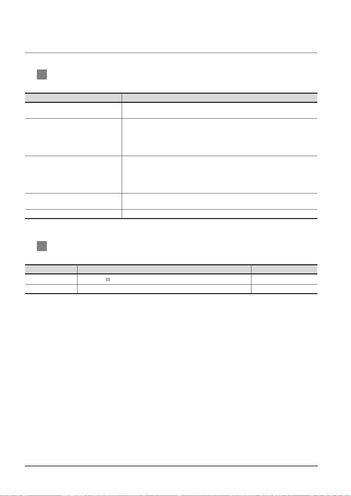
2.5.2 Connecting to serial communication module or computer link module
1 Connecting to serial communication module communicating with QCPU
(1) When using an RS-232 cable
The user is required to make a RS-232 cable for connecting GT SoftGOT1000 to a module.
The cables connection diagram indicated below.
(a) Connector specifications
Pin No. Signal code Signal name
Q computible C24 GT SoftGOT1000
Signal direction
1
OVERVIEW
2
SYSTEM
CONFIGURATION
1 CD Receive carrier detection
2 RD(RXD) Receive data
3 SD(TXD) Send data
4 DTR(ER) Data terminal ready
5 SG Send ground
6 DSR(DR) Data set ready
7 RS(RTS) Request to send
8 CS(CTS) Clear to send
9 RI(CI) Call indication
(b) Connection diagram
1) Connection example which can turn ON/OFF CD signal (No. 1 pin)
Serial communication module
side
Signal code Pin No. Signal code
CD 1 CD
RD(RXD) 2 RD(RXD)
SD(TXD) 3 SD(TXD)
DTR(ER) 4 DTR(ER)
SG 5 SG
DSR(DR) 6 DSR(DR)
RS(RTS) 7 RS(RTS)
CS(CTS) 8 CS(CTS)
R1(CI) 9
(Connection example for full duplex/half duplex communication)
Cable Connection and Signal Direction
GT SoftGOT1000
(Personal computer) side
INTERNAL DEVICE
3
4
SCREEN
5
OPERATING
6
7
INTERFACE
SPECIFICATIONS
CONFIGURATION
METHOD
FUNCTIONS
FUNCTION
2.5 Connection Cable
2.5.2 Connecting to serial communication module or computer link module
8
TROUBLESHOOTING
APPENDICES
2 - 21
Page 42

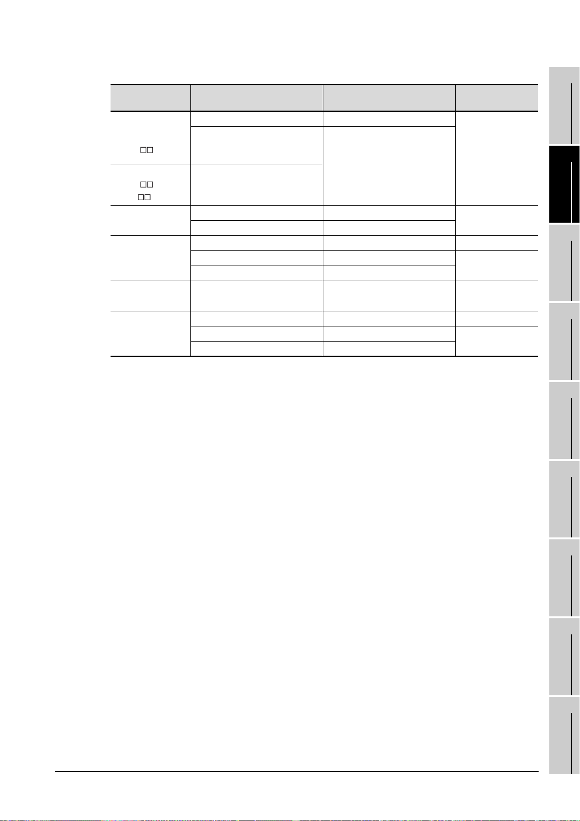
2) Connection example which cannot turn ON/OFF CD signal (No. 1 pin)
Connection example for exercising DC code control or DTR/DSR control
Serial communication module
side
Signal code Pin No. Signal code
CD 1 CD
RD(RXD) 2 RD(RXD)
SD(TXD) 3 SD(TXD)
DTR(ER) 4 DTR(ER)
SG 5 SG
DSR(DR) 6 DSR(DR)
RS(RTS) 7 RS(RTS)
CS(CTS) 8 CS(CTS)
R1(CI) 9
Cable Connection and Signal Direction
(Connection example for full duplex communication)
GT SoftGOT1000 (Personal
computer) side
2 - 22
2.5 Connection Cable
2.5.2 Connecting to serial communication module or computer link module
Page 43

2 Connecting to serial communication module or computer link module communicating
AC30N2A
(For personal computer side 25 pin D-sub connector
with QnACPU, ACPU, or motion controller CPU (A series)
(1) When using an RS-232 cable
(a) Using the product of Mitsubishi Erectric make.
RS-232 cable
1
OVERVIEW
2
SYSTEM
CONFIGURATION
(b) When using an RS-232 cable prerared by user
The cable connection diagrams are indicated below.
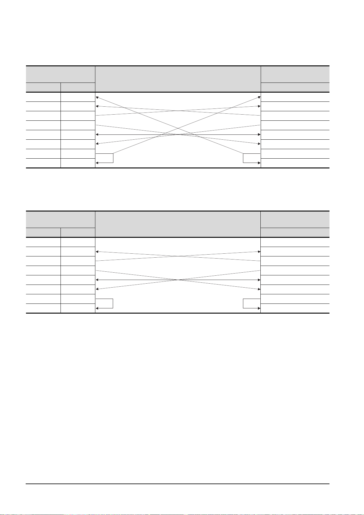
For QnA Series (large-scale QC24(N))
1) Example of connection to an external device that allows the CD signal (No.8 pin) to be turned ON/OFF
Serial communication
module side
Signal code Pin No. Signal code
FG 1 FG
SD (TXD) 2 SD (TXD)
RD (RXD) 3 RD (RXD)
RS 4 RS
CS (CTS) 5 CS (CTS)
DSR (DR) 6 DSR (DR)
SG 7 SG
CD 8 CD
DTR (ER) 20 DTR (ER)
* DC code control or DTR/DSR control is enabled by connecting the QC24 (N) to an external device as shown
above.
(Connection example for full duplex/half duplex communication)
Cable Connection and Signal Direction
2) Example of connection to an external device that does not allow the CD signal (No. 8 pin) to be turned
ON/OFF
Serial communication
module side
Signal code Pin No. Signal code
FG 1 FG
SD (TXD) 2 SD (TXD)
RD (RXD) 3 RD (RXD)
RS 4 RS
CS (CTS) 5 CS (CTS)
DSR (DR) 6 DSR (DR)
SG 7 SG
CD 8 CD
DTR (ER) 20 DTR (ER)
* DC code control or DTR/DSR control is enabled by connecting the QC24 (N) to an external device as shown
above.
Cable Connection and Signal Direction
(Connection example for full duplex communication)
GT SoftGOT1000 (Personal
computer) side
GT SoftGOT1000 (Personal
computer) side
INTERNAL DEVICE
3
4
SCREEN
5
OPERATING
6
7
INTERFACE
8
SPECIFICATIONS
CONFIGURATION
METHOD
FUNCTIONS
FUNCTION
TROUBLESHOOTING
2.5.2 Connecting to serial communication module or computer link module
2.5 Connection Cable
APPENDICES
2 - 23
Page 44
1) Example of connection to an external device that allows the CD signal (No.1 pin) to be turned ON/OFF
For QnA Series (compact-scale QC24(N))1)
Serial communication
module side
Signal code Pin No. Signal code
CD 1 CD
RD (RXD) 2 RD (RXD)
SD (TXD) 3 SD (TXD)
DTR (ER) 4 DTR (ER)
SG 5 SG
DSR (DR) 6 DSR (DR)
RS (RTS) 7 RS (RTS)
CS (CTS) 8 CS (CTS)
(Connection example for full duplex/half duplex communication)
Cable Connection and Signal Direction
GT SoftGOT1000 (Personal
computer) side
* DC code control or DTR/DSR control is enabled by connecting the QC24 (N) to an external device as shown
above.
2) Example of connection to an external device that does not allow the CD signal (No. 1 pin) to be turned
ON/OFF
Serial communication
module side
Signal code Pin No. Signal code
CD 1 CD
RD (RXD) 2 RD (RXD)
SD (TXD) 3 SD (TXD)
DTR (ER) 4 DTR (ER)
SG 5 SG
DSR (DR) 6 DSR (DR)
RS (RTS) 7 RS (RTS)
CS (CTS) 8 CS (CTS)
Cable Connection and Signal Direction
(Connection example for full duplex communication)
GT SoftGOT1000 (Personal
computer) side
2 - 24
* DC code control or DTR/DSR control is enabled by connecting the QC24 (N) to an external device as shown
above.
2.5 Connection Cable
2.5.2 Connecting to serial communication module or computer link module
Page 45
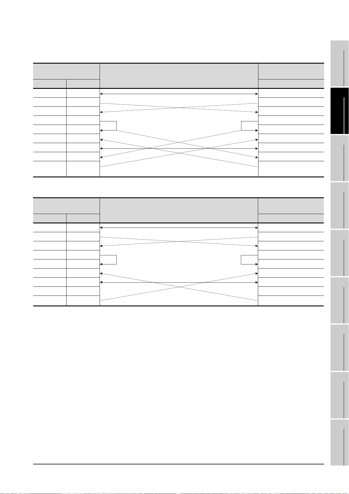
1) Connection example 1 when the C24 (computer link module) has a 25-pin connector
For A Series
1
Computer link module side
Signal code Pin No. Signal code
FG 1 FG
SD (TXD) 2 SD (TXD)
RD (RXD) 3 RD (RXD)
RS 4 RS
CS (CTS) 5 CS (CTS)
DSR (DR) 6 DSR (DR)
SG 7 SG
CD 8 CD
DTR (ER) 20 DTR (ER)
Cable Connection and Signal Direction
GT SoftGOT1000 (Personal
computer) side
2) Connection example 2 when the C24 (computer link module) has a 25-pin connector
Computer link module side
Signal code Pin No. Signal code
FG 1 FG
SD (TXD) 2 SD (TXD)
RD (RXD) 3 RD (RXD)
RS 4 RS
CS (CTS) 5 CS (CTS)
DSR (DR) 6 DSR (DR)
SG 7 SG
CD 8 CD
DTR (ER) 20 DTR (ER)
* When performing a communication in the connection shown above, the CD signal is not required to be
connected.
For the RS-232C CD terminal check setting (set by the buffer memory address "10BH"), specify "without CD
terminal check (writing "1")".
Cable Connection and Signal Direction
GT SoftGOT1000 (Personal
computer) side
OVERVIEW
2
SYSTEM
CONFIGURATION
3
SPECIFICATIONS
4
SCREEN
CONFIGURATION
5
OPERATING
METHOD
6
FUNCTIONS
7
2.5 Connection Cable
2.5.2 Connecting to serial communication module or computer link module
2 - 25
INTERNAL DEVICE
INTERFACE
FUNCTION
8
TROUBLESHOOTING
APPENDICES
Page 46

3) Connection example 1 when the C24 (computer link module) has a 9-pin connector
Computer link module side
Signal code Pin No. Signal code
CD 1 CD
RD (RXD) 2 RD (RXD)
SD (TXD) 3 SD (TXD)
DTR (ER) 4 DTR (ER)
SG 5 SG
DSR (DR) 6 DSR (DR)
RS (RTS) 7 RS (RTS)
CS (CTS) 8 CS (CTS)
Cable Connection and Signal Direction
GT SoftGOT1000 (Personal
computer) side
4) Connection example 2 when the C24 (computer link module) has a 9-pin connector
Computer link module side
Signal code Pin No. Signal code
CD 1 CD
RD (RXD) 2 RD (RXD)
SD (TXD) 3 SD (TXD)
DTR (ER) 4 DTR (ER)
SG 5 SG
DSR (DR) 6 DSR (DR)
RS (RTS) 7 RS (RTS)
CS (CTS) 8 CS (CTS)
Cable Connection and Signal Direction
*1 DC code control or DTR/DSR control is enabled by connecting the DTR and DSR signals of the computer link
module to an external device as shown above.
*2 When performing a communication in the connection shown above, the CD signal is not required to be
connected.
For the RS-232C CD terminal check setting (set by the buffer memory address "10BH"), specify "without CD
terminal check (writing "1")".
GT SoftGOT1000 (Personal
computer) side
2 - 26
2.5 Connection Cable
2.5.2 Connecting to serial communication module or computer link module
Page 47

2.5.3 Connecting to interface board or network module
1 MELSECNET/H connection, MELSECNET/10 connection
The cables are the same as the fiber-optic cables and coaxial cables used in the MELSECNET/H or
MELSECNET/10 network system.
Refer to the following for details of cables.
Q corresponding MELSECNET/H Network System Reference Manual (PLC to PLC
network)
2 CC-Link IE controller network connection
The cables are the same as the fiber-optic cables used in the CC-Link IE controller network.
Refer to the following for details of cables.
CC-Link IE Controller Network Reference Manual
1
OVERVIEW
2
SYSTEM
CONFIGURATION
3
SPECIFICATIONS
2.5.4 Connecting to Ethernet module or Ethernet board/card
Use a cable applicable to the Ethernet module or the Ethernet board/card to be used.
4
SCREEN
5
OPERATING
6
7
CONFIGURATION
METHOD
FUNCTIONS
2.5 Connection Cable
2.5.3 Connecting to interface board or network module
2 - 27
INTERNAL DEVICE
INTERFACE
FUNCTION
8
TROUBLESHOOTING
APPENDICES
Page 48

2.5.5 Connecting to CNC
1 Connecting to CNC C70
(1) Direct CPU connection, computer link connection, MELSECNET/H connection, MELSECNET/10
connection
Connect GT SoftGOT1000 to the QCPU (Q mode) in the multiple CPU system.
The cable for connecting to the CNC C70 is the same as that for connecting to the QCPU.
(2) Display I/F connection
The cable for connecting to the CNC C70 is the same as that for connecting to the QCPU via the
Ethernet connection.
Use a cable applicable to the CNC C70 to be used.
2 Connecting to MELDAS C6/C64
(1) Direct CPU connection
The user is required to make a conversion cable for connecting to the MELDAS C6/C64.
The following describes the connection diagram, connector and others for each cable.
(a) Connection diagram
PC (GT SoftGOT1000) side
Signal name Pin No. Pin No. Signal name
GND 1 1GND
RD(RXD) 2 -
SD(TXD) 3 -
GND 5 -
DR(DSR) 6 6SD(TXD)
CS(CTS) 8 -
Cable connection and signal direction
MELDAS C6/C64
(TERMINAL) siide
11 GN D
16 RD(RXD)
18 ER(DTR)
(b) Connector specifications
• PC side connector
Use the connector compatible with the PC side.
• MELDAS C6/C64 side connector
Use the connector compatible with MELDAS C6/C64 side.
For details, refer to the following manual.
User's Manual for the MELDAS C6/C64
2 - 28
(c) Precautions for creating cables
The length of the conversion cable must be 15m or shorter.
(2) Ethernet connection
Use a cable applicable to the Ethernet module to be used.
2.5 Connection Cable
2.5.5 Connecting to CNC
Page 49

2.5.6 Connecting to robot controller
1 Connecting to CRnQ-700
Connect GT SoftGOT1000 to the QCPU (Q mode) in the multiple CPU system.
The cable for connecting to the CRnQ-700 is the same as that for connecting to the QCPU.
2 Connecting to CRnD-700
The cable for connecting to the CRnD-700 is the same as that for connecting to the QCPU via the
Ethernet connection.
Use a cable applicable to the CRnD-700 to be used.
1
OVERVIEW
2
SYSTEM
CONFIGURATION
3
SPECIFICATIONS
4
INTERNAL DEVICE
SCREEN
5
OPERATING
6
7
INTERFACE
8
CONFIGURATION
METHOD
FUNCTIONS
FUNCTION
2.5 Connection Cable
2.5.6 Connecting to robot controller
TROUBLESHOOTING
APPENDICES
2 - 29
Page 50

2.5.7 Connecting to Omron PLC CPU
GT09-C30R20101-9P(3m) (For the 9-pin D-sub connector of the PC
1 When using a product made in Mitsubishi Electric System Service Co., Ltd.
RS-232 cable
2 When using an RS-232 cable prepared by user
The following describes the connection diagram, connector and others for each cable.
(1) Connection diagram
PC (GT SoftGOT1000) side
Signal name Pin No. Pin No. Signal name
CD 1 1FG
RD (RXD) 2 2SD
SD (TXD) 3 3RD
ER (DTR) 4 4RS
SG 5 5CS
DR (DSR) 6 6-
RS (RTS) 7 7FR
CS (CTS) 8 8ER
-9 9SG
Cable connection and signal direction
Omron products side
(2) Connector specifications
(a) PC side connector
Use the connector compatible with the PC side.
(b) Omron PLC CPU side connector
Use the connector compatible with Omron PLC CPU side.
For details, refer to the following manual.
User's Manual for Omron PLC CPU
2 - 30
(3) Precautions for creating cables
The length of the cable must be 15m or less.
2.5 Connection Cable
2.5.7 Connecting to Omron PLC CPU
Page 51

2.5.8 Connecting to YASKAWA PLC CPU
GT09-C30R20201-9P (3m) (For the 9-pin D-sub connector of the personal computer side)
GT09-C30R20203-9P (3m) (For the 9-pin D-sub connector of the personal computer side)
1 Serial connection
For serial connection, the used cable differs according to the connection destination.
The following lists the available cables for each destination.
Model name Connection cable
GL120
GL130
CP-9300MS
(CP-9300MC compatible/no
compatible)
CP-9200(H)
PLC CPU
MEMOBUS module
Communication module
PROGIC-8
MP-920
MP-930
MP-940 • User-created cable (RS-232 cable 4))
JAMSC-IF60
JAMSC-IF61
217IF
CP-217IF
217IF-01
218IF-01
For connecting to
port 1
For connecting to
port 2
For connecting to
CN1
For connecting to
CN2
• GT09-C30R20201-9P
• User-created cable (RS-232 cable 1))
• GT09-C30R20203-9P
• User-created cable (RS-232 cable 3))
• GT09-C30R20201-9P
• User-created cable (RS-232 cable 1))
• GT09-C30R20201-9P
• User-created cable (RS-232 cable 1))
• User-created cable (RS-232 cable 2))
• GT09-C30R20201-9P
• User-created cable (RS-232 cable 1))
• GT09-C30R20201-9P
• User-created cable (RS-232 cable 1))
• GT09-C30R20201-9P
• User-created cable (RS-232 cable 1))
• User-created cable (RS-232 cable 5))
• GT09-C30R20201-9P
• User-created cable (RS-232 cable 1))
1
OVERVIEW
2
SYSTEM
CONFIGURATION
3
SPECIFICATIONS
4
SCREEN
CONFIGURATION
5
OPERATING
METHOD
6
(1) When using MITSUBISHI SYSTEM & SERVICE product
RS-232 cable
(2) When using an RS-232 cable prepared by user
The following describes the connection diagram, connector and others for each cable.
2.5.8 Connecting to YASKAWA PLC CPU
2.5 Connection Cable
2 - 31
FUNCTIONS
7
INTERNAL DEVICE
INTERFACE
FUNCTION
8
TROUBLESHOOTING
APPENDICES
Page 52

(a) Connection diagram
• RS-232 cable 1)
Personal computer
(GT SoftGOT1000) side
Signal name Pin No. Pin No. Signal name
CD 1 1FG
RD(RXD) 2 2TXD
SD(TXD) 3 3RXD
ER(DTR) 4 4RTS
SG 5 5CTS
DR(DSR) 6 6DSR
RS(RTS) 7 7GND
CS(CTS) 8 8EST
-9 9DTR
Cable connection and signal direction
YASKAWA products side
• RS-232 cable 2)
Personal computer
(GT SoftGOT1000) side
Signal name Pin No. Pin No. Signal name
CD 1 1FG
RD(RXD) 2 2TXD
SD(TXD) 3 3RXD
ER(DTR) 4 4RTS
SG 5 5CTS
DR(DSR) 6 6DSR
RS(RTS) 7 7GND
CS(CTS) 8 8NC
-9 9DTR
Cable connection and signal direction
YASKAWA products side
• RS-232 cable 3)
Personal computer
(GT SoftGOT1000) side
Signal name Pin No. Pin No. Signal name
CD 1 1FG
RD(RXD) 2 2TXD
SD(TXD) 3 3RXD
ER(DTR) 4 4RTS
SG 5 5OP/CTS
DR(DSR) 6 6DSR
RS(RTS) 7 7GND
CS(CTS) 8 8PWR
-9 9DTR
2 - 32
2.5 Connection Cable
Cable connection and signal direction
2.5.8 Connecting to YASKAWA PLC CPU
YASKAWA products side
Page 53

• RS-232 cable 4)
1
Personal computer
(GT SoftGOT1000) side
Signal name Pin No. Pin No. Signal name
CD 1 Clamped on hood
RD(RXD) 2 1TXD
SD(TXD) 3 3RXD
ER(DTR) 4 12 RTS
SG 5 6CTS
DR(DSR) 6 2-
RS(RTS) 7 14 GND
CS(CTS) 8
-9
Cable connection and signal direction
YASKAWA products side
• RS-232 cable 5)
Personal computer
(GT SoftGOT1000) side
Signal name Pin No. Pin No. Signal name
CD 1 1FG
RD(RXD) 2 2TXD
SD(TXD) 3 3RXD
ER(DTR) 4 4RS
SG 5 5CS
DR(DSR) 6 6DSR
RS(RTS) 7 7SG
CS(CTS) 8 8CD
-9 20 DTR
Cable connection and signal direction
YASKAWA products side
OVERVIEW
2
SYSTEM
CONFIGURATION
3
SPECIFICATIONS
4
SCREEN
CONFIGURATION
5
OPERATING
METHOD
6
(b) Connector specification
• Personal computer side connecter
Use the connector compatible with the personal computer side.
• YASKAWA PLC CPU side connector
Use the connector compatible with YASKAWA PLC CPU side.
For details, refer to the following manual.
User's manual for YASKAWA PLC CPU
(c) Precautions for creating cables
The length of the cable must be 15m or less.
2 Ethernet connection
Be sure to use cables compatible with the communication module to be used if the connection is made
via Ethernet.
2.5 Connection Cable
2.5.8 Connecting to YASKAWA PLC CPU
2 - 33
FUNCTIONS
7
INTERNAL DEVICE
INTERFACE
FUNCTION
8
TROUBLESHOOTING
APPENDICES
Page 54

2.5.9 Connecting to YOKOGAWA PLC
1 Ethernet connection
Be sure to use cables compatible with the Ethernet interface module to be used if the connection is
made via Ethernet.
2 - 34
2.5 Connection Cable
2.5.9 Connecting to YOKOGAWA PLC
Page 55

2.6 Access Range for Monitoring
For the access range for monitoring of GT SoftGOT1000, refer to the following manual.
GT Designer2 Version Screen Design Manual
1
OVERVIEW
2
SYSTEM
CONFIGURATION
3
SPECIFICATIONS
4
INTERNAL DEVICE
SCREEN
5
OPERATING
6
7
INTERFACE
8
CONFIGURATION
METHOD
FUNCTIONS
FUNCTION
2.6 Access Range for Monitoring
TROUBLESHOOTING
APPENDICES
2 - 35
Page 56

3. SPECIFICATIONS
3.1 Specifications
3.1.1 Specifications of the GT SoftGOT1000
The specifications of the GT SoftGOT1000 is shown below.
Item Specifications
Resolution (dots)
Display color (color) 65536
Memory capacity 57MB
Connection type
*1 X and Y are resolution values set by the user.
640 480, 800 600, 1024 768, 1280 1024, 1600 1200, X Y (Resolution specification)
For using MITSUBISHI PLC: Bus connection, Direct connection to CPU,
Computer link connection, MELSECNET/H connection,
MELSECNET/10 connection, CC-Link IE controller network
connection, Ethernet connection
For using CNC:
CNC C70
MELDAS C6/C64
For using a robot controller:
CRnQ-700
CRnD-700
For using OMRON PLC: Direct connection to CPU
For using YASKAWA PLC: Direct connection to CPU, Computer link connection, Ethernet
For using YOKOGAWA PLC: Ethernet connection
5.3.1 Environment setup dialog box
Direct connection to CPU, Computer link connection,
MELSECNET/H connection, MELSECNET/10 connection,
CC-Link IE controller network connection, Display I/F connection
Direct connection to CPU, Ethernet connection
Direct connection to CPU, Computer link connection,
MELSECNET/H connection, MELSECNET/10 connection,
CC-Link IE controller network connection, Ethernet connection
Ethernet connection
connection
*1
3 - 1
Project data display
(1) Full screen mode
If the resolution of the personal computer used is the same as that of GT
SoftGOT1000, it is recommended to hide the frame and menu part using the full
screen mode function.
When not using the full screen mode function, the top/bottom and left/right parts of
the display are hidden by the frame and menu part.
(2) GOT type and resolution
For the GT SoftGOT1000, set the same resolution as the GOT type of the project
data created with GT Designer2.
If the resolution settings are different, the project data cannot be read into the GOT.
3.1 Specifications
3.1.1 Specifications of the GT SoftGOT1000
Page 57

3.1.2 License key specifications
To use GT SoftGOT1000, license key is required.
License key has the following two types.
1
Model name Attachment type
GT15-SGTKEY-U Attached to USB port
GT15-SGTKEY-P Attached to parallel port
Be sure to attach the license key before starting monitoring on GT SoftGOT1000.
When starting monitoring without a license key, GT SoftGOT1000 automatically ends in about two hours.
Also, from starting monitoring to exiting it, use GT SoftGOT1000 with the license key attached.
If the license key is disconnected during monitoring, the GT SoftGOT1000 will exit automatically.
License key
(1) Before using license key
The license key is authentificated by OS as a connected device.
Thus, the System Driver (device driver) needs to be installed as other connected
devices.
As the license key can be accessed via the System Driver, the access to the
license key is not allowed when the System Driver is not installed.
(2) License key use target
The GT15-SGTKEY-U and GT15-SGTKEY-P are dedicated for GT SoftGOT1000.
They cannot be used for GT SoftGOT2.
OVERVIEW
2
SYSTEM
CONFIGURATION
3
SPECIFICATIONS
4
SCREEN
CONFIGURATION
5
INTERNAL DEVICE
OPERATING
6
7
INTERFACE
8
METHOD
FUNCTIONS
FUNCTION
TROUBLESHOOTING
3.1 Specifications
3.1.2 License key specifications
APPENDICES
3 - 2
Page 58

3.2 Functions that Cannot Be Used
In GT SoftGOT1000, some functions available in GT16 cannot be used.
The following table shows unusable functions.
Function category Function name
Time setting, Transparent mode,
Clean, Video/RGB setting ,
Multimedia setting
Screen save time, Screen save backlight,
Battery alarm display, Brightness,contrast
Key sensitivity, Key reaction speed,
Touch panel calibration, Touch detection mode
Maintenance timing setting, Addtion times reset,
GOT start time
OS/project information
System monitor function, Barcode function,
Video display, RGB display,
Multimedia function, External I/O function,
Operation panel function*3, Backup/restore function,
CNC data I/O function, RFID function
Operator authentication (External authentication/fingerprint authentication)
Ladder monitor function, List editor for MELSEC-A,
List editor for MELSEC-FX, Intelligent module monitor function,
Network monitor function, Q motion monitor function,
Servo amplifier monitor function, CNC monitor function,
Gateway function, MES interface function,
SFC monitor function, Ladder editor function
FA transparent functions, Human sensor function,
RGB output
Utility functions
Extension function
Option functions
Others
*1
*1 Refer to the following manual for details of Utility function.
*2 Refer to the following manual for details of Extension and Option functions.
*3 With the keyboard input function, operations equivalent to the operation panel function can be available.
GOT main
unit setup
Display
GOT setup
Operation
GOT
maintenance
function
Communication setting Communication setting
Debug Debug
Self check Self check
Data control Data control
Data control
*2
*2
OS/project
information
GT16 User's Manual
GOT1000 Series Extended/Option Functions Manual
3 - 3
3.2 Functions that Cannot Be Used
Page 59
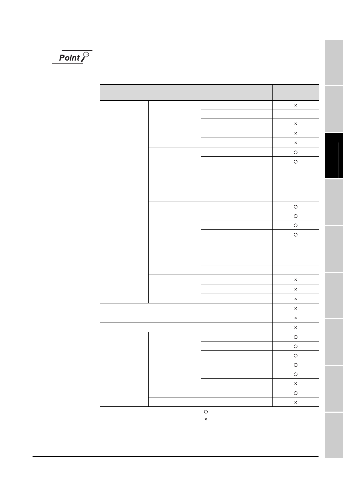
Utility operability
In GT SoftGOT1000, some functions do not operate even though they can be set.
The operability on GT SoftGOT1000 is shown below.
Operability on GT
SoftGOT1000
GOT setup
Communication setting
Debug
Self check
Data control
Item
GOT main unit setup
Display
Operation
GOT maintenance
function
Data control
OS/project information
Time setting
Transparent mode -
Clean
Video/RGB setting
Multimedia setting
Language
Opening screen time
Screen save time -
Screen save backlight -
Battery alarm display -
Brightness, contrast -
Buzzer volume
Window move buzzer
Security setting
Utility call key
Key sensitivity -
Key reaction speed -
Touch panel calibration -
Touch Detection Mode -
Maintenance timing setting
Addition times reset
GOT start time
Alarm information
Advanced Recipe information
Logging information
Operation log information
Hard copy information
Special data information
Operator information
: Operable
: Inoperable
- : Setting is not required on GT SoftGOT1000 (Some
items can be set but do not operate.)
INTERNAL DEVICE
1
OVERVIEW
2
SYSTEM
CONFIGURATION
3
SPECIFICATIONS
4
SCREEN
CONFIGURATION
5
OPERATING
METHOD
6
FUNCTIONS
7
INTERFACE
8
TROUBLESHOOTING
FUNCTION
3.2 Functions that Cannot Be Used
APPENDICES
3 - 4
Page 60

3.3 Precautions
MELSOFT(installation folder)
SGT1000
Multi_SGT
No01 Folder for module No.1
Drive Stores a virtual drive
A
E
B
No02 Folder for module No.2
Drive Stores a virtual drive
A
E
B
3.3.1 Precautions for using the GT Soft GOT1000
1 Numerical Display
When the [View Format] of [Numerical Display] is set to [Real] and if illegal value is stored, illegal value
will be displayed on GT Soft GOT1000. (GOT displays [non].)
2 Time display
The clock data of the personal computer is used for clock display when monitoring GT SoftGOT1000.
(GOT reads and shows the clock data of the PLC CPU.)
When controling a system using clock data, set the same clock data for the PLC CPU and personal
computer.
GT SoftGOT1000 does not support the daylight saving function. Do not check [Automatically adjust
clock for daylight saving changes] on the personal computer.
3 GT Soft GOT1000 Versions
Be sure to use the GT Soft GOT1000 of the same version as the GT Designer2 that the project data is
created.
When using different versions of GT SoftGOT1000 and GT Designer2, the file may not be opened,
functions/settings may be invalid, or the GT Soft GOT1000 may not work correctly.
Refer to the following for the project data compatibility.
4 Virtual drive
The GT SoftGOT1000 uses the following folder located on the hard disk of a personal computer as a
virtual drive.
A virtual drive is created for each module.
Any other folders can be set as the virtual A drive, the virtual B drive, and the virtual E drive.
For changing folders for the virtual drives, refer to the following.
3 - 5
Appendix 1 Applicable Project Data
5.3 Environment Setup
3.3 Precautions
3.3.1 Precautions for using the GT Soft GOT1000
Page 61

5 Logging, advanced recipe, operation log, operator authentication
The logging information, advanced recipe information, operation log information, and operator info.
management cannot be displayed with the utility.
For using the logging information, advanced recipe information, operation log information, and operator
info. management, set special function switches.
For special function switches, refer to the following manual.
GT Designer2 Version2 Screen Design Manual
1
OVERVIEW
2
6 Printer to output function
(1) Hard copy output destination
Hard copy output destination can be specified on GT Designer2 or GT SoftGOT1000.
Settings that are required for each hard copy output destination are shown below.
(a) In the case [Printer] is selected as the output destination on the Hard copy setting screen of GT
Designer2.
Hard copy output Setting at GT SoftGOT1000
File save destination (Hard
copy (File Save))
Virtual A Drive
(GT1sgHardcopy)
Virtual A Drive
(GT1sgHardcopy)
(b) In the case [File] is selected as the output destination on the Hard copy setting screen of GT
Designer2
.
Hard copy output Setting at GT SoftGOT1000
File save destination (Hard
copy (File Save))
Virtual A Drive
(GT1sgHardcopy)
The save file destination that
was specified on the Hard
copy setting screen of GT
Designer2
Refer to the following for hard copy functions.
GT Designer2 Version Screen Design Manual
Refer to the following for Page Setup.
6.2.3 Performing page setup
Refer to the following for Environment Setup.
5.3 Environment Setup
[Print to printer (Hard Copy
Printing
Yes C he ck -
No Uncheck -
Printing
No - Select [Default].
No - Select [Project Data Setting].
Function)] on the Page
Setup screen
[Print to printer (Hard Copy
Function)] on the Page
Setup screen
[File Output (Hard Copy
Function)] on the
Environment Setup screen
-: Setting ineffective
[File Output (Hard Copy
Function)] on the
Environment Setup screen
-: Setting ineffective
INTERNAL DEVICE
SYSTEM
CONFIGURATION
3
SPECIFICATIONS
4
SCREEN
CONFIGURATION
5
OPERATING
METHOD
6
FUNCTIONS
7
INTERFACE
8
TROUBLESHOOTING
FUNCTION
3.3 Precautions
3.3.1 Precautions for using the GT Soft GOT1000
APPENDICES
3 - 6
Page 62

(2) System alarm during hard copying
The system alarm will not be displayed during hard copying.
Refer to the following for troubleshooting for the hard copy function.
8.4 Troubleshooting for Print
8.5 Troubleshooting for File Save Problems
(3) Report function
Data cannot be output to a printer directly.
Print images (in CSV format) are stored to the virtual A drive of a personal computer once. Output
these images in each file to a printer.
7 Resource data storage destination
Resource data is stored to the virtual A drive or a user-specified folder with the configuration shown
below.
Storage destination Function
Advanced alarm, Alarm history, Logging,
Recipe, Advanced recipe, Report (Print),
Hard copy (File save)*1, Hard copy (Print), Operation log
Hard copy (File save)*
Hard copy (Print)
1
Virtual A drive or
user-specified
folder
*1 File save destination for each file can be specified in the [File Output (Hard Copy Function)] menu in the
Folder name specified
in project data
G1SgtReport Report (Print)
G1SgtHardcopy
Environment Setup dialog box.
Refer to the following for Environment Setup dialog box.
5.3.1 Environment setup dialog box
3 - 7
3.3 Precautions
3.3.1 Precautions for using the GT Soft GOT1000
Page 63

The file formats of resource data are described below.
Function Folder name File format and file name
File name set in project data
*****.G1A
Advanced alarm Folder name set in project data
Alarm function Folder name set in project data
Logging Folder name set in project data
Recipe Folder name set in project data
Advanced recipe Folder name set in project data
Report (Print)
Hard copy (File save)
Hard copy (Print) G1SgtHardcopy (Fixed) HARDCOPY.BMP (Fixed)
Operation log function Folder name set in project data
*1
*2
*1 When using any language other than Japanese and English for the report screen and outputting the data in CSV
file, characters may not be displayed correctly.
Do not use any language other than Japanese and English.
*2 File save destination for each file can be specified in the [File Output (Hard Copy Function)] menu in the
Environment Setup dialog box.
Refer to the following for Environment Setup.
5.3.1 Environment setup dialog box
G1SgtReport (Fixed) REP00001.CSV - REP00008.CSV
G1SgtHardcopy (Fixed)
File name set in project data
File name set in project data
*****.CSV
File name set in project data
*****.TXT
File name set in project data
*****.G1H
File name set in project dataa
*****.CSV
File name set in project data
*****.G1L
File name set in project data
*****.CSV
File name set in project data
*****.TXT
File name set in project data
*****.CSV
File name set in project data
*****.G1P
File name set in project data
*****.CSV
File name set in project data
*****.TXT
SNAP0001.BMP - SNAP9999.BMP
SNAP0001.JPG - SNAP9999.JPG
File name set in project data
*****.BMP
File name set in project data
*****.JPG
File name set in project data
*****.G1O
File name set in project data
*****.CSV
File name set in project data
*****.TXT
INTERNAL DEVICE
1
OVERVIEW
2
SYSTEM
CONFIGURATION
3
SPECIFICATIONS
4
SCREEN
CONFIGURATION
5
OPERATING
METHOD
6
FUNCTIONS
7
INTERFACE
8
TROUBLESHOOTING
FUNCTION
3.3 Precautions
3.3.1 Precautions for using the GT Soft GOT1000
APPENDICES
3 - 8
Page 64

Precautions on file names for the virtual drive
As a folder name for the virtual drive, only ASCII characters (excluding “|”, “,” and “;”)
can be used with up to 78 characters.
Set the file name with up to 256 characters including the path name for file storage
destination and file name to be stored (including extension).
Two-byte and one-byte Japanese kana are considered as 2 characters.
8 Functions in which data are stored in the memory card in advance by the user
When registering parts of BMP/JPEG files and document display data, store the data to the virtual A
drive, the virtual B drive, or the virtual E drive.
(The drive to be used depends on the specifications and setting of the object.)
For details of each function, refer to the following manual.
GT Designer2 Version Screen Design Manual
Except for the virtual drive, GT SoftGOT1000 does not recognize BPM/JPEG files and other files.
Example) Storage destination for document display data
\MELSOFT\SGT1000\Multi_SGT\No01\Drive\A\DOCIMG
3 - 9
3.3 Precautions
3.3.1 Precautions for using the GT Soft GOT1000
Page 65

3.3.2 Precautions on license key
1 When attaching GT15-SGTKEY-U
(1) Installation/uninstallation of the System Driver
Before installing or uninstalling the System Driver, disconnect the GT15-SGTKEY-U.
When installing the System Driver with the GT15-SGTKEY-U attached, the installation of USB may
be failed.
When the installation is failed, uninstall the System Driver after disconnecting the GT15-SGTKEYU, and install it again.
1
OVERVIEW
2
SYSTEM
CONFIGURATION
2 When attaching GT15-SGTKEY-P
(1) Using GT15-SGTKEY-P
The GT15-SGTKEY-P can be used only with the parallel port built in a personal computer as
standard.
It cannot be used with the parallel port added by extension or a converter.
(2) Using GT15-SGTKEY-P with other devices simultaneously
The following devices cannot be used at the same port as the GT15-SGTKEY-P.
• SCSI interface for parallel port
• Floppy disc drive, hard disc drive, CD-ROM or ZIP drive connected to parallel port
• Devices that use a data communication method other than the standard network specification,
including parallel port communication type Interlink and Centronics printer interface
(3) Attaching GT15-SGTKEY-P
Connect the GT15-SGTKEY-P between the printer switching device and personal computer.
3 When using the System Driver
(1) Installing the System Driver
Use the System Driver included in the GT Works2 Version2/GT Designer2 Version2 of Ver. 2.25B.
When using a System Driver earlier than Ver. 2.25B or later, GT15-SGTKEY-U cannot be used.
(GT15-SGTKEY-P can be used.)
3
4
SCREEN
5
OPERATING
6
SPECIFICATIONS
CONFIGURATION
METHOD
3.3 Precautions
3.3.2 Precautions on license key
3 - 10
FUNCTIONS
7
INTERNAL DEVICE
INTERFACE
FUNCTION
8
TROUBLESHOOTING
APPENDICES
Page 66
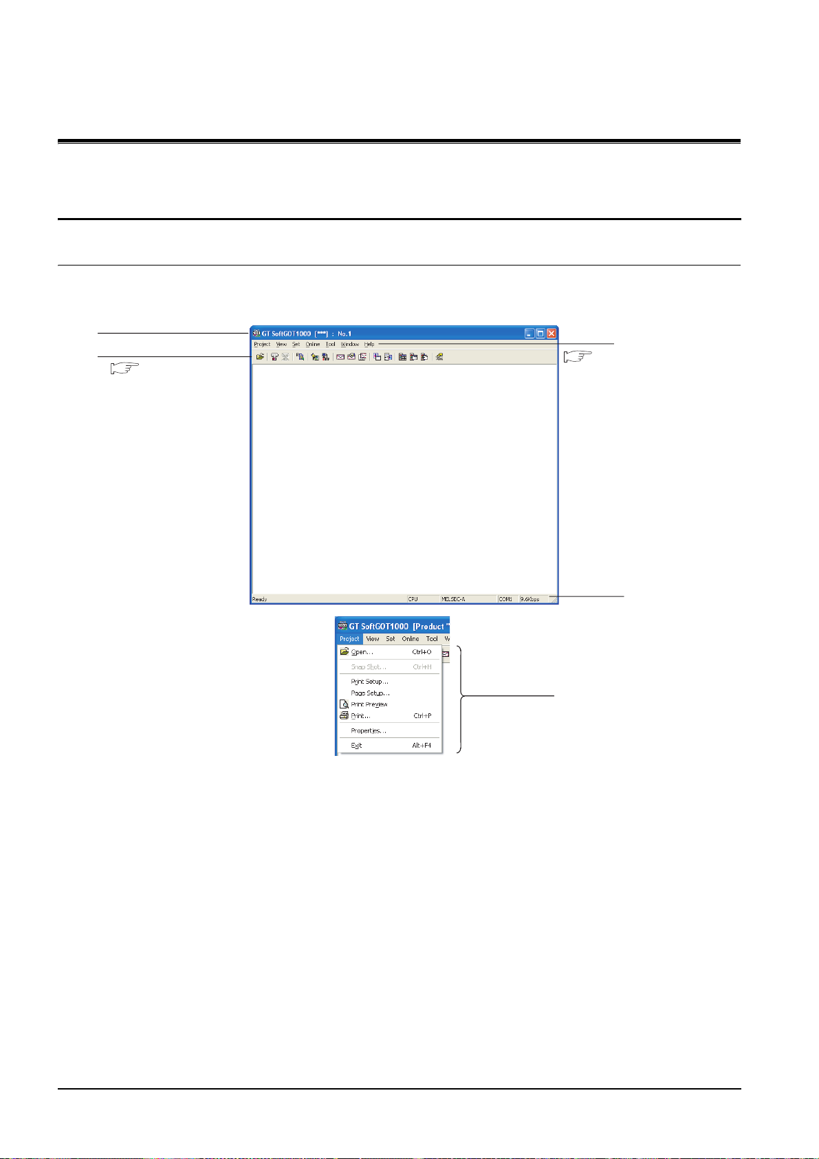
4. SCREEN CONFIGURATION
Title Bar
Tool Bar
Menu Bar
Status Bar
Dropdown menu
Section 4.3 Tool bar
Section 4.2 Menu Bar
4.1 Screen Configuration and Basic Operation
4.1.1 Screen configuration
This section describes screen configuration.
4 - 1
4.1 Screen Configuration and Basic Operation
4.1.1 Screen configuration
Page 67

4.1.2 Basic operation
(1) List box
(2) Radio button
(3) Check box
(5) Text box
(4) Command button
(6) Up one level
(7) Display menu
(8) Creation of
new folder
OK
Cancel
This section describes basic operation.
1
(1) List box
Click to display the selection list, then click
and select an item.
(2) Radio button
Select an item by clicking the corresponding .
(3) Check box
When executing the item, click to put a
check mark .
(4) Command button
The command buttons such as and
are provided. Click the command button
indicating desired operation.
(5) Text box
Enter a text from the keyboard.
OVERVIEW
2
SYSTEM
CONFIGURATION
3
SPECIFICATIONS
4
SCREEN
CONFIGURATION
5
(6) Up one level
Displays the level one up from the current
folder.
(7) Display menu
Provides the viewing mode of the folders and
files in the current folder; select from detailed
display, list display and another modes.
(8) Creation of new folder
Creates a new folder.
INTERNAL DEVICE
OPERATING
6
7
INTERFACE
8
METHOD
FUNCTIONS
FUNCTION
TROUBLESHOOTING
4.1 Screen Configuration and Basic Operation
4.1.2 Basic operation
APPENDICES
4 - 2
Page 68

4.2 Menu Bar
This section describes commands assigned to the menu bar.
Project
The Project menu includes options for project data reading,
Snap Shot and printing.
View
The View menu includes the functions for switching the
toolbar, menu bar, and scroll bar between display and
nondisplay states. The menu includes the functions for
switching the full screen mode and back screen mode between
enabled and disabled states.
5. OPERATING METHOD 6. FUNCTIONS
Set
Online
5. OPERATING METHOD
The Set menu includes the functions for setting the
environment, mail, application start-up, and PX Developer. The
menu includes the functions for switching the keyboard input,
popup menu, close menu, and exit key between enabled and
disabled states.
6. FUNCTIONS
The Online menu includes functions for setting monitor start/
stop, starting in online mode enable/disable switching,
communication error dialog display/non-display and
communications.
5. OPERATING METHOD
4 - 3
4.2 Menu Bar
Page 69

To ol
Window
The Tool menu includes the function of displaying resource
data, file information in the PLC, and error information.
6. FUNCTIONS
The Window menu includes the function of window move.
1
OVERVIEW
2
SYSTEM
CONFIGURATION
Help
6. FUNCTIONS
The Help menu includes functions of viewing the PDF manual
related to the GT SoftGOT1000 and checking the software
version.
4.4 Help
3
4
SCREEN
5
OPERATING
6
SPECIFICATIONS
CONFIGURATION
METHOD
4.2 Menu Bar
FUNCTIONS
7
INTERNAL DEVICE
INTERFACE
FUNCTION
8
TROUBLESHOOTING
APPENDICES
4 - 4
Page 70

4.3 Tool bar
This section describes the tool bar.
Name Description
Open a GT Designer2
file.
Monitor Start Starts monitoring.
Monit or Sto p Stops mo nitoring.
Resource Data Displays resource data.
Environment Setup Performs environment settings for GT SoftGOT1000.
Communication Setup Performs communication settings for GT SoftGOT1000.
Mail setup Performs mail settings such as dial-up, send address.
Opens the project data created with GT Designer2.
Mail Condition Disables the mail send setting of the project data.
Mail History Displays the operation history of mail sendings.
Application Start-up
Setting
Application Start-up
History
PX Developer Function
Call Setting
PX Developer Function
Call Sub-Setting
PX Developer Function
Call Sub-Setting
Keyboard Switches keyboard input enable/disable.
Allows settings for starting up applications from GT SoftGOT1000.
Shows operation histories of application start-up.
Performs the PX Developer call settings.
Performs the PX Developer call sub-settings.
Shows operation histories at calling monitor tool functions for in PX Developer.
4 - 5
4.3 Tool bar
Page 71

4.4 Help
Click.
Switches the current display
to the page of the selected
section.
Returns to INDEX MENU.
Using Help allows viewing of the GT SoftGOT1000 related PDF manuals and the software version check.
1
Before viewing the PDF manual
To view the PDF manual, GT Manual and Adobe Reader must be installed.
1 Operating method
1 Click an item within [Help].
Item Description
[Index] Displays the PDF manual list.
[About GT SoftGOT1000...] Used to check the GT SoftGOT1000 version.
[Connect to MEL FANweb...]
Connects to the Information site for Mitsubishi Electric Industrial Automation
Products, MELFANSweb.
2 Viewing a PDF manual (When [Index] is selected)
1 After operation in , the following screen appears. Click the manual to be viewed.
OVERVIEW
2
SYSTEM
CONFIGURATION
3
SPECIFICATIONS
4
SCREEN
CONFIGURATION
5
*The illustration above is given as an example and different from the actual page.
2 The selected manual is displayed. (For details of the Adobe Reader operating method, refer to Help
of Adobe Reader .)
*The illustration above is given as an example and different from the actual page.
INTERNAL DEVICE
OPERATING
6
7
INTERFACE
8
METHOD
FUNCTIONS
FUNCTION
TROUBLESHOOTING
4.4 Help
APPENDICES
4 - 6
Page 72

3 Clicking the icon in the lower right of INDEX MENU switches the screens between GOT1000 and
Click here when viewing
from the CD-ROM.
Click here when viewing
the installed manual.
(Example: Screen for changing to GOT900 Series screen)
OK
GOT900 series.
*The illustration above is given as an example and different from the actual page.
3 Confirming GT SoftGOT1000 version (When [About GT SoftGOT1000...] is selected)
1 After operation in , the screen about GT SoftGOT1000 is displayed.
(Example: For Version 2.27D)
Item Description
GT SoftGOT1000 Displays GT SoftGOT1000 version.
Name Displays the name entered during GT SoftGOT1000 installation.
Company Displays the company name entered during GT SoftGOT1000 installation.
Closes the About GT SoftGOT1000 screen.
4 - 7
4.4 Help
Page 73

5. OPERATING METHOD
Start
Attach the license key.
Start the GT SoftGOT1000.
Make settings for Communication Setup.
Make settings for Environment Setup.
Start monitoring.
Open a project data.
Stop monitoring.
Exit the GT SoftGOT1000.
Exit
3.1.2 License key specifications
3.3.2 Precautions on license key
GT Designer2 Version Basic Operation/Data Transfer
Manual
5.2 Communication Setup
5.3 Environment Setup
5.4 Starting Monitoring
5.5 Opening the Project
5.7 Monitor Stop
5.8 Exiting from GT SoftGOT1000
1
5.1 Operating Procedure
The following describes the operating procedure of GT SoftGOT1000.
OVERVIEW
2
SYSTEM
CONFIGURATION
3
SPECIFICATIONS
4
SCREEN
CONFIGURATION
5
INTERNAL DEVICE
OPERATING
6
7
INTERFACE
8
METHOD
FUNCTIONS
FUNCTION
TROUBLESHOOTING
5.1 Operating Procedure
APPENDICES
5 - 1
Page 74

5.2 Communication Setup
OK
In Communication Setup, set the type of the PLC CPU to be connected, the communication time-out period,
etc.
1 Perform either of the following operations.
• Clicking (Communication Setup)
• Select [Online] [Communication Setup] from the menu.
• Right-click the mouse to select [Communication Setup] from the menu.
2 The Communication Setup dialog box is displayed.
3 Set each item and click the button.
Communication Setup
Make Communication Setup before starting monitoring.
After start of monitoring on GT SoftGOT1000, Communication Setup cannot be
changed.
(The "Communication Error Dialog" setting can be changed during monitoring.)
5.2.1 Communication setup dialog box
5 - 2
5.2 Communication Setup
5.2.1 Communication setup dialog box
Page 75

Item Description
Select the connection method of GT SoftGOT1000.
CPU : Select this option for direct connection to CPU via the RS-232 cable.
USB : Select this option for direct connection to CPU via the USB cable.
C24 : Select this option when computer link connection is used.
Connection
*1
-
CPU/C24 When selecting CPU/C24 in the connection method, set the following items.
Comm. port
Baud rate
Timeout
Host
Other
Retry
CC IE Control When selecting [CC IE Control] in the connection method, set the following item.
Monitor Speed
Ethernet When selecting "Ethernet" in the connection method, set the following items.
NET No.
PC No.
Port No.
Wait Time
Option Set the options when selecting [YASKAWA] from [CPU] on the selecting method.
Host Add.
Wait Time
NET/H : Select this option when using the MELSECNET/H interface board.
Select "NET/H" when using the GT SoftGOT1000 in MELSECNET/10 mode.
CC IE Control : Select this option when using the CC-Link IE controller network interface board.
Ethernet : Select this option when Ethernet connection is used.
BUS : Select [BUS] when the bus connection is used.
If CPU/USB/C24/NET/H/CC IE Control/Ethernet is selected as the connection method, specify the connection
destination.
When CPU/USB is selected : Selects the type of CPU to be connected.
When C24 is selected : Selects the type of computer link module or serial communication module to be
connected.
When NET/H/CC IE Control is selected
: Select the interface board mounted on the personal computer to be used.
When Ethernet is selected : Select the model of a programmable controller to be connected.
Choose the communication port on the personal computer side.
COM1 to COM6
Set the transmission speed to/from the CPU.
Set the baud rate to be used.
When connecting a QnA/A series computer link, set the same baud rate as the one set in the computer link/serial
communication module to be used.
For connection with the FXCPU, select the baud rate supported by the connected FXCPU.
When the set baud rate is not supported, communication is made at 9.6kbps.
When selecting a transmission speed that is not supported by OMRON SYSMAC, a communication error occurs.
Set the timeout period and retry count.
Depending on the settings on the [Connection] menu, some items cannot be set.
Set the timeout period for host monitor.
"3" to "90" (seconds)
Set the timeout period for other station monitor.
"3" to "90" (seconds)
Set the number of retries.
"0" to "10" (times)
Set the monitor speed for CC-Link IE controller network.
[High], [Normal], [Low]
Set the network number of GT SoftGOT1000.
"1" to "239"
Set the station number of GT SoftGOT1000.
The station number must be different f rom the PLC No. of the Ethernet module to b e monitored. "1" to "64"
Set the port number of GT SoftGOT1000.
*2
"1024" to "65535"
Set the transmission wait time to reduce the load on the network and target PLC.
"0" to "10000" (x 10 ms)
Specify the host address (the station number of a programmable controller to which connects GT SoftGOT1000)
within the connection network.
[1] to [31]
Set the transmission time to reduce the loads of a network and a target programmable controller.
[0] to [30] (x 10ms)
5.2 Communication Setup
5.2.1 Communication setup dialog box
(Continued to next page)
5 - 3
1
OVERVIEW
2
SYSTEM
CONFIGURATION
3
SPECIFICATIONS
4
SCREEN
CONFIGURATION
5
OPERATING
METHOD
6
FUNCTIONS
7
INTERNAL DEVICE
INTERFACE
FUNCTION
8
TROUBLESHOOTING
APPENDICES
Page 76
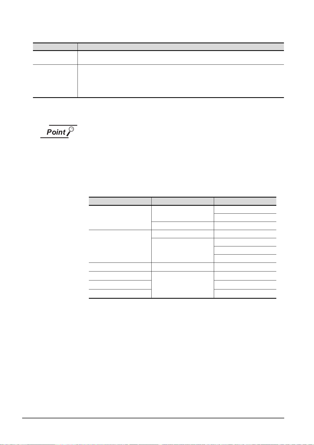
Item Description
Communication Error
Dialog
Device Entry Mode
*1 For using the CNC C70, select [MELSEC-Q].
*2 For communication via the Ethernet port of the QnUDE(H)CPU, the port No. is automatically specified, regadless
Enable this check box to display the error dialogue box in GT SoftGOT1000 when a communication error occurred.
Check the item to enable high-speed monitoring on GT SoftGOT1000.
When using the Device Entry Mode during FXCPU connection, the range of devices to be monitored may be
restricted, and monitoring may not be performed properly.
This setting is enabled only when selecting [MELSEC-Q] or [MELSEC-FX] from [CPU] or when [MELSEC-Q] from
[USB].
of the setting.
Precautions for using device entry mode (When the MELSEC-FX connection)
The precautions for applying the device entry mode are described below.
Apply the device entry mode after the adequate debugging.
(1) Devices that can be set
An error (Communication time out) may occur if the following device (Bit device) is
set.
For the device as objects, set other than the devices shown below when applying
the device entry mode.
Type of connected CPU Device name (Bit device) Device range
FX
series
0(S)
FX0N series
FX1 series
FX
series
1S
series
FX
1N
FX
series
2(C)
FX
2N(C)
Counter contact (C)
Special auxiliary relay (M) M8240 to M8255
Timer contact (T) T240 to T255
Counter contact (C)
Counter contact (C) C224 to 239
Counter contact (C)
series
C224 to C239
C240 to C255
C128 to C143
C224 to 239
C240 to 255
C192 to 207
C192 to 207
C192 to 207
(2) When using the offset function
When offset function is applied, the device range above may be monitored during
an unintended moment and an error (Communication time out) may occur.
Create the project data so that any offset will not operate for the devices above.
(3) Measures for errors
The error mentioned by (1) and (2) is displayed in the system alarm.
When applying the device entry mode, it is recommended to set system alarm to
the project data.
5 - 4
5.2 Communication Setup
5.2.1 Communication setup dialog box
Page 77

5.2.2 How to Set Up the Computer Link Connection
When communicating GT SoftGOT1000 to a serial communication module or a computer link module, set
the switches of the module as shown in the next page.
For setting details of serial communication module and computer link module, refer to the manual of the
module to be used.
The following table shows the transmission specifications for communicating GT SoftGOT1000 to a serial
communication module or a computer link module.
Refer to the following for Communication Setup.
5.2 Communication Setup
1
OVERVIEW
2
SYSTEM
CONFIGURATION
3
SPECIFICATIONS
4
Serial communication
module
(Q series)
Serial communication
module
(QnA series)
Computer link module
Model name
QJ71C24(-R2),
QJ71C24N(-R2),
QJ71CMO, QJ71CMON
AJ71QC24N(-R2),
A1SJ71QC24N(-R2)
AJ71QC24(-R2),
A1SJ71QC24(-R2)
AJ71C24-S8, AJ71UC24
A1SJ71C24-R2/-PRF,
A1SJ71UC24-R2/-PRF
Transmission
speed
9600bps/
19200bps/
38400bps/
57600bps/
115200bps
9600bps/
19200bps
Settings
Data length Stop bit Parity bit Sum check
8 bits 1 bit Yes (odd) Yes
INTERNAL DEVICE
SCREEN
5
OPERATING
6
7
INTERFACE
8
CONFIGURATION
METHOD
FUNCTIONS
FUNCTION
5.2 Communication Setup
5.2.2 How to Set Up the Computer Link Connection
TROUBLESHOOTING
APPENDICES
5 - 5
Page 78

1 When connecting to serial communication module (Q series)
No switch setting is required for the serial communication module (Q series). GX Developer(GOT
monitors via it without making switch setting in the I/O assignment setting of GX Developer.)
The following settings are also available for monitoring, according to the CH (interface) of the module to
be connected with GT SoftGOT1000.
For the GX Developer operating method, refer to the GX Developer Operating Manual.
Channel where GT
SoftGOT1000 is connected
CH1 0000 0000 0000
CH2 0000 0000 0000
Switch 1 Switch 2 Switch 3 Switch 4 Switch 5
Settings
2 When connecting to serial communication module (QnA series)
Switch
9600bps 19200bps 38400bps 57600bps 115200bps
Station number switch 0
Mode switch 5
sw01 OFF
sw02 ON
sw03 ON
sw04 OFF
sw05 OFF
sw06 ON
sw07 ON
sw08 OFF
sw09 ON OFF ON OFF ON
sw10 OFFONONONON
sw11 ON ON ON OFF OFF
sw12 OFF OFF OFF ON ON
*1 38400 bps, 57600 bps and 115200 bps can be set only for the following modules.
• AJ71QC24N(-R2) • A1SJ71QC24N(-R2)
Baud rate (Transmission speed)
*1
5 - 6
5.2 Communication Setup
5.2.2 How to Set Up the Computer Link Connection
Page 79

3 When connecting to computer link module
(1) When connecting to an AJ71C24-S8
The following shows the settings when connecting to an AJ71C24-S8.
RS-232 communication
Switch
9600bps 19200bps
Station number switch 0
Mode switch 1
sw11 OFF
sw12 ON
sw13 ON OFF
sw14 OFF ON
sw15 ON ON
sw16 ON
sw17 OFF
sw18 OFF
sw21 ON
sw22 ON
sw23 OFF
sw24 OFF
(2) When connecting to an AJ71UC24
The following shows the settings when connecting to an AJ71UC24.
Baud rate (Transmission speed)
1
OVERVIEW
2
SYSTEM
CONFIGURATION
3
SPECIFICATIONS
4
SCREEN
CONFIGURATION
5
RS-232 communication
Switch
9600bps 19200bps
Station number switch 0
Mode switch 1
sw11 OFF
sw12 ON
sw13 ON OFF
sw14 OFF ON
sw15 ON ON
sw16 ON
sw17 OFF
sw18 OFF
sw21 ON
sw22 ON
sw23 ON
sw24 OFF
Baud rate (Transmission speed)
INTERNAL DEVICE
OPERATING
6
7
INTERFACE
8
METHOD
FUNCTIONS
FUNCTION
TROUBLESHOOTING
5.2 Communication Setup
5.2.2 How to Set Up the Computer Link Connection
APPENDICES
5 - 7
Page 80

(3) When connecting to an A1SJ71UC24-R2, A1SJ71C24-R2, A1SJ71UC24-PRF and A1SJ71C24-
PRF.
The following shows the settings when connecting to an A1SJ71UC24-R2, A1SJ71C24-R2,
A1SJ71UC24-PRF and A1SJ71C24-PRF.
RS-232 communication
Switch
9600bps 19200bps
Station number switch No applicable switch
Mode switch 1
SW01 No applicable switch
SW02 No applicable switch
sw03 OFF
sw04 ON
sw05 ON OFF
sw06 OFF ON
sw07 ON ON
sw08 ON
sw09 ON
sw10 OFF
sw11 OFF
sw12 ON
Baud rate (Transmission speed)
5 - 8
5.2 Communication Setup
5.2.2 How to Set Up the Computer Link Connection
Page 81

5.2.3 How to Set Up the Ethernet Connection
Ethernet connection
(1) Before Ethernet connection
Read the manual for the Ethernet module to be used thoroughly and understand it
fully before setting up the Ethernet connection.
(2) Time-out error
If many devices (including GT SoftGOT1000) are connected, line traffic may
become dense, causing a time-out error. If a time-out error occurs, reduce the
number of connected devices or increase the time-out value in the
Communication Setup of GT SoftGOT1000.
1
OVERVIEW
2
SYSTEM
CONFIGURATION
3
SPECIFICATIONS
4
INTERNAL DEVICE
SCREEN
5
OPERATING
6
7
INTERFACE
8
CONFIGURATION
METHOD
FUNCTIONS
FUNCTION
5.2 Communication Setup
5.2.3 How to Set Up the Ethernet Connection
TROUBLESHOOTING
APPENDICES
5 - 9
Page 82

1 When using Built-in Ethernet port QCPU (one-to-one connection, multiple connection)
:5001
<GT SoftGOT1000>
:1
:3
:192.168.0.18
N/W No.
PC No.
IP address
Port No. :5006
:1
:1
:192.168.0.1
:5006
:1
:2
:192.168.0.2
<Built-in Ethernet port QCPU>
Other station
N/W No.
PC No.
IP address
Port No.
<Built-in Ethernet port QCPU>
Host
N/W No.
PC No.
IP address
Port No.
The setting items and precautions are shown below for communicating GT SoftGOT1000 to Built-in
Ethernet port QCPU.
This section describes the system configuration to monitor the host as shown below.
When monitoring other stations, follow the same procedure as the host.
Setting items
The port No. for Built-in Ethernet port QCPU is fixed to "5006".
Refer to the following for how to set the N/W No., PLC No./PC No., IP address and
port No. of the Ethernet module and GT SoftGOT1000.
This section (7)
The following shows the procedure for communicating GT SoftGOT1000 to Built-in Ethernet port
QCPU.
(1) Before setting
(a) Monitoring the CPUs on other networks
Monitoring the CPUs on other networks requires the routing parameter to be set.
Refer to the following for how to set the routing parameters.
This section (4) Routing Parameter Setting
This section (7)(b) Routing Parameter Setting
(b) Precautions for communication
When multiple network devices (including GT SoftGOT1000) are connected to the same
segment, the network load may increase, and the communication speed may slow down
between GT SoftGOT1000 and the PLC.
The following actions may improve the communication performance.
• Use a switching hub.
(2) Compatible models
Q03UDECPU, Q04UDEHCPU, Q06UDEHCPU, Q13UDEHCPU,
Q26UDEHCPU
• Use the high-speed 100BASE-TX (100Mbps).
• Reduce the monitoring points of GT SoftGOT1000.
Compatible models
5 - 10
5.2 Communication Setup
5.2.3 How to Set Up the Ethernet Connection
Page 83
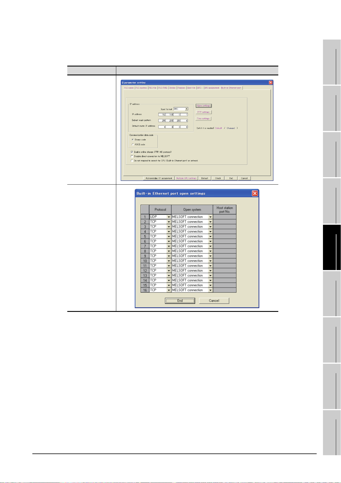
(3) Q parameter setting (Setting on GX Developer)
Set the Built-in Ethernet port for the Q parameter setting. (multiple connection only)
Item Setting Screen Examples
Built-in Ethernet port
1
OVERVIEW
2
SYSTEM
CONFIGURATION
3
SPECIFICATIONS
4
Open settings
Operation settings
To make communications with GX Developer, ask the person in charge of the network about the IP
address setting to confirm, and set the IP address.
Since "any" values may be set to the other items, set them according to the specifications of the
other node and application connected to the Ethernet module.
The following are the operation setting items that may be set to "any" values on GX Developer.
(a) Communication data code
Either "Binary code" or "ASCII code" may be specified.
(b) Initial Timing
Independently of this setting, communications can be made from GX Developer if the PLC
CPU is at a STOP.
(c) Enable Write at RUN time
Independently of this setting, online program correction or device test can be performed from
GX Developer.
INTERNAL DEVICE
SCREEN
5
OPERATING
6
7
INTERFACE
8
CONFIGURATION
METHOD
FUNCTIONS
FUNCTION
TROUBLESHOOTING
5.2 Communication Setup
5.2.3 How to Set Up the Ethernet Connection
APPENDICES
5 - 11
Page 84

(4) Routing Parameter Setting
Up to 64 [Transfer Network No.]s can be set.
The same [Transfer Network No.] cannot be set twice or more.
The host (GOT) can access up to 64 [Transfer Network No.]s as a request source.
Item Range
Transfer Network No. 1 to 239
Relay Network No. 1 to 239
Relay Station No. 1 to 64
Routing parameter setting for the request source
The GOT at the request source also requires the routing parameter setting.
Refer to the following for routing parameter setting.
This section (7)(b) Routing Parameter Setting
(5) Setting on the personal computer
Set the IP address.
5 - 12
5.2 Communication Setup
5.2.3 How to Set Up the Ethernet Connection
Page 85

(6) Communications check
(a) Ping test
When ready to communicate, execute the Ping command at the command prompt on the
Windows .
1
OVERVIEW
When connections are OK
C:\>ping 192. 168. 0. 2
Reply from 192. 168. 0. 2:bytes=32 time<10ms TTL=32
When connections are not good
C:\>ping 192. 168. 0. 2
Request timed out.
When the Ping test is not verified, check the connections of the cable and module, and settings,
including the IP address, for Windows .
Ping test
The Ping test can be performed using GX Developer (SW6D5C-GPPW 6.01B or
later).
Refer to the GX Developer Operating Manual for more details on the Ping test.
Refer to the following for details of the Ping test.
GX Developer Version Operating Manual
(b) Station monitoring function
For details on the station monitoring function, refer to the following manual.
GOT1000 Series Connection Manual
(7) Settings with GT Designer2 and GT SoftGOT1000
(a) Ethernet setting
Make the following settings on the Ethernet setting dialog box of GT Designer2.
Refer to the following for details of the Ethernet settings.
2
SYSTEM
CONFIGURATION
3
SPECIFICATIONS
4
SCREEN
CONFIGURATION
5
OPERATING
METHOD
6
5.2.4 Setting on GT Designer2
5.2 Communication Setup
5.2.3 How to Set Up the Ethernet Connection
5 - 13
FUNCTIONS
7
INTERNAL DEVICE
INTERFACE
FUNCTION
8
TROUBLESHOOTING
APPENDICES
Page 86

(b) Routing Parameter Setting
Set the routing parameter in the Routing Information Setting dialog box of GT Designer2.
Up to 64 [Transfer Network No.]s can be set.
The same [Transfer Network No.] cannot be set twice or more.
The host (GOT) can access up to 64 [Transfer Network No.]s as a request source.
Routing parameter setting
Communication within the host network does not require routing parameter setting.
Refer to the following for details of routing parameter setting.
Q Corresponding MELSECNET/H Network System Reference Manual (PLC to PLC
network)
5 - 14
Item Range
Transfer Network No. 1 to 239
Relay Network No. 1 to 239
Relay Station No. 1 to 64
Routing parameter setting for the relay station
The PLC at the relay station also requires the routing parameter setting.
Refer to the following for routing parameter setting.
This section (4) Routing Parameter Setting
5.2 Communication Setup
5.2.3 How to Set Up the Ethernet Connection
Page 87

(c) Communication setup
Make the settings in the Communication Setup dialog box of GT SoftGOT1000.
Refer to the following for details of Communication Setup.
5.2.1 Communication setup dialog box
1
OVERVIEW
2
SYSTEM
CONFIGURATION
3
SPECIFICATIONS
4
INTERNAL DEVICE
SCREEN
5
OPERATING
6
7
INTERFACE
8
CONFIGURATION
METHOD
FUNCTIONS
FUNCTION
5.2 Communication Setup
5.2.3 How to Set Up the Ethernet Connection
TROUBLESHOOTING
APPENDICES
5 - 15
Page 88

2 When using Ethernet module (Q series)
The setting items and precautions are shown below for communicating GT SoftGOT1000 to the PLC
CPU via the Ethernet module (Q series).
This section describes the system configuration to monitor the host as shown below.
When monitoring other stations, follow the same procedure as the host.
Ethernet module (Q series)
<Q series E71> Other station
N/W No.
PLC No.
IP address
Port No. : 5001
Ethernet module (Q series)
<Q series E71> Host
N/W No.
PLC No.
IP address
Port No.
: 1
: 2
: 192.168.0.2
: 5001
: 1
: 1
: 192.168.0.1
<GT SoftGOT1000>
N/W No.
PC No.
IP address
Port No.
: 1
: 3
: 192.168.0.3
: 5001
Setting items
The port No. for the Ethernet module (Q series) is fixed to "5001".
Refer to the following for how to set the N/W No., PLC No./PC No., IP address and
port No. of the Ethernet module and GT SoftGOT1000.
This section (7)
The following shows the procedure for communicating GT SoftGOT1000 to the PLC CPU via the
Ethernet module (Q series).
(1) Before setting
(a) Monitoring the CPUs on other networks
Monitoring the CPUs on other networks requires the routing parameter to be set.
Refer to the following for how to set the routing parameters.
This section (4) Routing Parameter Setting
This section (7)(b) Routing Parameter Setting
(b) Precautions for communication
When multiple network devices (including GT SoftGOT1000) are connected to the same
segment, the network load may increase, and the communication speed may slow down
between GT SoftGOT1000 and the PLC.
The following actions may improve the communication performance.
• Use a switching hub.
• Use the high-speed 100BASE-TX (100Mbps).
• Reduce the monitoring points of GT SoftGOT1000.
(2) Compatible models
Compatible models
QJ71E71-100, QJ71E71-B5, QJ71E71-B2, QJ71E71
5 - 16
5.2 Communication Setup
5.2.3 How to Set Up the Ethernet Connection
Page 89

(3) Network parameter setting (Setting on GX Developer)
Parameter setting can be made from the MELSECNET/ETHERNET network parameter setting
screen.
Set the network type, first I/O No., network No., group No., station number, mode and operation
setting.
1
OVERVIEW
Item Setting Screen Examples
Ethernet Parameters
Operation Setting
2
SYSTEM
CONFIGURATION
3
SPECIFICATIONS
4
SCREEN
CONFIGURATION
5
OPERATING
METHOD
Operation settings
To make communications with GX Developer, ask the person in charge of the network about the IP
address setting to confirm, and set the IP address.
Since "any" values may be set to the other items, set them according to the specifications of the
other node and application connected to the Ethernet module.
The following are the operation setting items that may be set to "any" values on GX Developer.
(a) Communication data code
Either "Binary code" or "ASCII code" may be specified.
(b) Initial Timing
Independently of this setting, communications can be made from GX Developer if the PLC
CPU is at a STOP.
(c) Enable Write at RUN time
Independently of this setting, online program correction or device test can be performed from
GX Developer.
INTERNAL DEVICE
6
7
INTERFACE
8
FUNCTIONS
FUNCTION
TROUBLESHOOTING
5.2 Communication Setup
5.2.3 How to Set Up the Ethernet Connection
APPENDICES
5 - 17
Page 90

(4) Routing Parameter Setting
Up to 64 [Transfer Network No.]s can be set.
The same [Transfer Network No.] cannot be set twice or more.
The host (GOT) can access up to 64 [Transfer Network No.]s as a request source.
Item Range
Transfer Network No. 1 to 239
Relay Network No. 1 to 239
Relay Station No. 1 to 64
Routing parameter setting for the request source
The GOT at the request source also requires the routing parameter setting.
Refer to the following for routing parameter setting.
This section (7)(b) Routing Parameter Setting
(5) Setting on the personal computer
Set the IP address.
5 - 18
5.2 Communication Setup
5.2.3 How to Set Up the Ethernet Connection
Page 91

(6) Communications check
(a) Ping test
When ready to communicate, execute the Ping command at the command prompt on the
Windows .
1
OVERVIEW
When connections are OK
C:\>ping 192. 168. 0. 2
Reply from 192. 168. 0. 2:bytes=32 time<10ms TTL=32
When connections are not good
C:\>ping 192. 168. 0. 2
Request timed out.
When the Ping test is not verified, check the connections of the cable and module, and settings,
including the IP address, for Windows .
Ping test
The Ping test can be performed using GX Developer (SW6D5C-GPPW 6.01B or
later).
Refer to the GX Developer Operating Manual for more details on the Ping test.
Refer to the following for details of the Ping test.
GX Developer Version Operating Manual
(b) Station monitoring function
For details on the station monitoring function, refer to the following manual.
GOT1000 Series Connection Manual
(7) Settings with GT Designer2 and GT SoftGOT1000
(a) Ethernet setting
Make the following settings on the Ethernet setting dialog box of GT Designer2.
Refer to the following for details of the Ethernet settings.
2
SYSTEM
CONFIGURATION
3
SPECIFICATIONS
4
SCREEN
CONFIGURATION
5
OPERATING
METHOD
6
5.2.4 Setting on GT Designer2
5.2 Communication Setup
5.2.3 How to Set Up the Ethernet Connection
5 - 19
FUNCTIONS
7
INTERNAL DEVICE
INTERFACE
FUNCTION
8
TROUBLESHOOTING
APPENDICES
Page 92

(b) Routing Parameter Setting
Set the routing parameter in the Routing Information Setting dialog box of GT Designer2.
Up to 64 [Transfer Network No.]s can be set.
The same [Transfer Network No.] cannot be set twice or more.
The host (GOT) can access up to 64 [Transfer Network No.]s as a request source.
Routing parameter setting
Communication within the host network does not require routing parameter setting.
Refer to the following for details of routing parameter setting.
Q Corresponding MELSECNET/H Network System Reference Manual (PLC to PLC
network)
Item Range
Transfer Network No. 1 to 239
Relay Network No. 1 to 239
Relay Station No. 1 to 64
Routing parameter setting for the relay station
The PLC at the relay station also requires the routing parameter setting.
Refer to the following for routing parameter setting.
This section (4) Routing Parameter Setting
5 - 20
5.2 Communication Setup
5.2.3 How to Set Up the Ethernet Connection
Page 93

(c) Communication setup
Make the settings in the Communication Setup dialog box of GT SoftGOT1000.
Refer to the following for details of Communication Setup.
5.2.1 Communication setup dialog box
1
OVERVIEW
2
SYSTEM
CONFIGURATION
3
SPECIFICATIONS
4
INTERNAL DEVICE
SCREEN
5
OPERATING
6
7
INTERFACE
8
CONFIGURATION
METHOD
FUNCTIONS
FUNCTION
5.2 Communication Setup
5.2.3 How to Set Up the Ethernet Connection
TROUBLESHOOTING
APPENDICES
5 - 21
Page 94

3 When using Ethernet module (QnA series)
The setting items and precautions are shown below for communicating GT SoftGOT1000 to the PLC
CPU via the Ethernet module (QnA series).
This section describes the system configuration to monitor the host as shown below.
When monitoring other stations, follow the same procedure as the host.
Ethernet module (QnA series)
<QE71> Other station
N/W No.
PLC No.
IP address
Port No.
Ethernet module (QnA series)
<QE71> Host
N/W No.
PLC No.
IP address
Port No.
: 1
: 2
: 192.168.0.2
: 5001
: 1
: 1
: 192.168.0.1
: 5001
Setting items
The port No. for the Ethernet module (QnA series) is fixed to "5001".
Refer to the following for how to set the N/W No., PLC No./PC No., IP address and
port No. of the Ethernet module and GT SoftGOT1000.
<GT SoftGOT1000>
N/W No.
PC No.
IP address
Port No.
: 1
: 3
: 192.168.0.3
: 5001
This section (8)
The following shows the procedure for communicating GT SoftGOT1000 to the PLC CPU via the
Ethernet module (QnA series).
(1) Before setting
(a) Monitoring the CPUs on other networks
Monitoring the CPUs on other networks requires the routing parameter to be set.
Refer to the following for how to set the routing parameters.
This section (5) Routing Parameter Setting
This section (8)(b) Routing Parameter Setting
(b) Precautions for communication
• Only communications within the same segment are applicable.
No communications via a router or gateway can be monitored.
• When multiple network devices (including GT SoftGOT1000) are connected to the same
segment, the network load may increase, and the communication speed may slow down
between GT SoftGOT1000 and the PLC.
The following actions may improve the communication performance.
• Use a switching hub.
• Use the high-speed 100BASE-TX (100Mbps).
• Reduce the monitoring points of GT SoftGOT1000.
5 - 22
5.2 Communication Setup
5.2.3 How to Set Up the Ethernet Connection
Page 95

(2) Compatible models
AJ71QE71N3-T, AJ71QE71N-B5, AJ71QE71N-B2, AJ71QE71N-T, AJ71QE71N-B5T,
AJ71QE71, AJ71QE71-B5, A1SJ71QE71N3-T, A1SJ71QE71N-B5, A1SJ71QE71N-B2,
A1SJ71QE71N-T, A1SJ71QE71N-B5T, A1SJ71QE71-B5, A1SJ71QE71-B2
*1 When using AJ71QE71, AJ71QE71-B5, A1SJ71QE71-B2 or A1SJ71QE71-B5, use a module or PLC CPU of
function version B or later.
*1
Compatible models
(3) Ethernet module (QnA series) switch settings
Operation mode setting switch : 0 (online)
Automatic start mode : SW3 ON
When SW3 is ON, initial processing is performed independently of Y19 (initial processing request).
Communications are also enabled if the CPU module is stopped.
For the initial processing using Y19 (initial processing request), create the program for initial
processing while referring to the "For QnA Ethernet Interface Module User's Manual".
(4) Network parameter setting (Setting on GX Developer)
On the MELSECNET/Ethernet setting screen of network parameter, set the network type, starting
I/O No., network No., group No., station number and IP address.
Item Setting screen example
1
OVERVIEW
2
SYSTEM
CONFIGURATION
3
SPECIFICATIONS
4
Ethernet Parameters
IP Address Setting
INTERNAL DEVICE
SCREEN
5
OPERATING
6
7
INTERFACE
8
CONFIGURATION
METHOD
FUNCTIONS
FUNCTION
5.2 Communication Setup
5.2.3 How to Set Up the Ethernet Connection
TROUBLESHOOTING
APPENDICES
5 - 23
Page 96
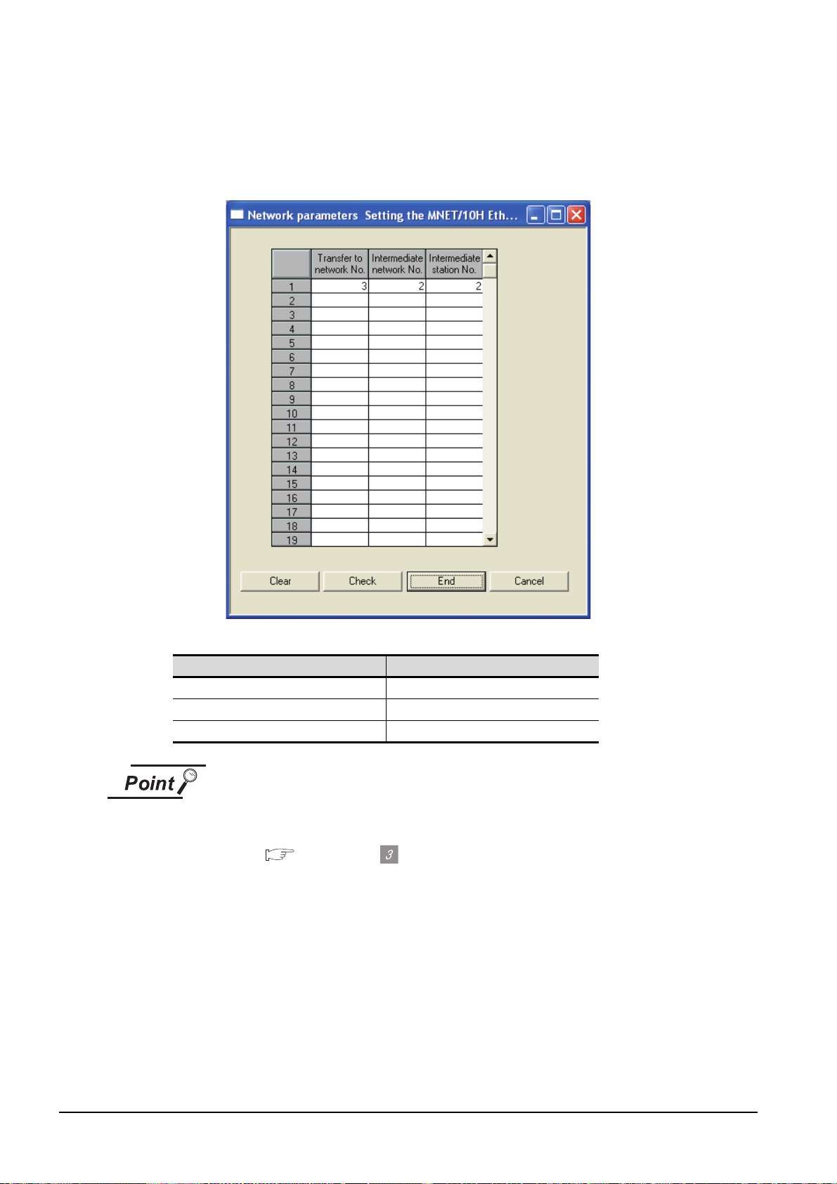
(5) Routing Parameter Setting
Up to 64 [Transfer Network No.]s can be set.
The same [Transfer Network No.] cannot be set twice or more.
The host (GOT) can access up to 64 [Transfer Network No.]s as a request source.
Item Range
Transfer Network No. 1 to 239
Relay Network No. 1 to 239
Relay Station No. 1 to 64
Routing parameter setting for the request source
The GOT at the request source also requires the routing parameter setting.
Refer to the following for routing parameter setting.
This section (8)(b) Routing Parameter Setting
(6) Setting on the personal computer
Set the IP address.
5 - 24
5.2 Communication Setup
5.2.3 How to Set Up the Ethernet Connection
Page 97

(7) Communications check
(a) Ping test
When ready to communicate, execute the Ping command at the command prompt on the
Windows .
1
OVERVIEW
When connections are OK
C:\>ping 192. 168. 0. 2
Reply from 192. 168. 0. 2:bytes=32 time<10ms TTL=32
When connections are not good
C:\>ping 192. 168. 0. 2
Request timed out.
When the Ping test is not verified, check the connections of the cable and module, and settings,
including the IP address, for Windows .
Ping test
The Ping test can be performed using GX Developer (SW6D5C-GPPW 6.01B or
later).
Refer to the GX Developer Operating Manual for more details on the Ping test.
Refer to the following for details of the Ping test.
GX Developer Version Operating Manual
(b) Station monitoring function
For details on the station monitoring function, refer to the following manual.
GOT1000 Series Connection Manual
(8) Settings with GT Designer2 and GT SoftGOT1000
(a) Ethernet setting
Make the following settings on the Ethernet setting dialog box of GT Designer2.
Refer to the following for details of the Ethernet settings.
5.2.4 Setting on GT Designer2
2
SYSTEM
CONFIGURATION
3
SPECIFICATIONS
4
SCREEN
CONFIGURATION
5
OPERATING
METHOD
6
FUNCTIONS
5.2 Communication Setup
5.2.3 How to Set Up the Ethernet Connection
5 - 25
7
INTERNAL DEVICE
INTERFACE
FUNCTION
8
TROUBLESHOOTING
APPENDICES
Page 98
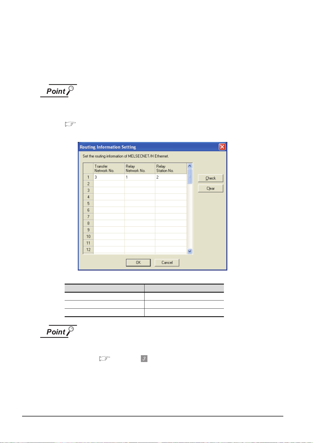
(b) Routing Parameter Setting
Set the routing parameter in the Routing Information Setting dialog box of GT Designer2.
Up to 64 [Transfer Network No.]s can be set.
The same [Transfer Network No.] cannot be set twice or more.
The host (GOT) can access up to 64 [Transfer Network No.]s as a request source.
Routing parameter setting
Communication within the host network does not require routing parameter setting.
Refer to the following for details of routing parameter setting.
Q Corresponding MELSECNET/H Network System Reference Manual (PLC to PLC
network)
5 - 26
Item Range
Transfer Network No. 1 to 239
Relay Network No. 1 to 239
Relay Station No. 1 to 64
Routing parameter setting for the relay station
The PLC at the relay station also requires the routing parameter setting.
Refer to the following for routing parameter setting.
This section (5) Routing Parameter Setting
5.2 Communication Setup
5.2.3 How to Set Up the Ethernet Connection
Page 99

(c) Communication setup
Make the settings in the Communication Setup dialog box of GT SoftGOT1000.
Refer to the following for details of Communication Setup.
5.2.1 Communication setup dialog box
1
OVERVIEW
2
SYSTEM
CONFIGURATION
3
SPECIFICATIONS
4
INTERNAL DEVICE
SCREEN
5
OPERATING
6
7
INTERFACE
8
CONFIGURATION
METHOD
FUNCTIONS
FUNCTION
5.2 Communication Setup
5.2.3 How to Set Up the Ethernet Connection
TROUBLESHOOTING
APPENDICES
5 - 27
Page 100

4 When using Ethernet module (A series)
<GT SoftGOT1000>
<E71> Host
N/W No. : 1
Port No. : 5001
IP address : 192.168.0.2
PLC No. : 2
<E71> Other station
N/W No. : 1
Port No. : 5001
IP address : 192.168.0.1
PLC No. : 1
N/W No. : 1
Port No. : 5001
IP address : 192.168.0.3
PC No. : 3
Ethernet module (A series)
Ethernet module (A series)
The setting items and precautions are shown below for communicating GT SoftGOT1000 to the PLC
CPU via the Ethernet module (A series).
This section describes the system configuration to monitor the host as shown below.
When monitoring other stations, follow the same procedure as the host.
Precautions for setting items
The N/W No. and PLC No. to be specified for Ethernet connection to the E71 should
be those set as desired on GT Designer2.
Refer to the following for how to set the N/W No., PLC No./PC No., IP address and
port No. of the Ethernet module and GT SoftGOT1000.
This section (7)
The following shows the procedure for performing communications via E71.
(1) Before setting
(a) Monitoring precautions
The connection target cannot be monitored via MELSECTNET/10 or MELSECNET/H.
(b) Communication precautions
• Only communications within the same segment can be monitored.
No communications via a router or gateway can be monitored.
• A connection of multiple pieces of network equipment (including GT SoftGOT1000) to a
segment may increase the network load and slow down the communication between the GT
SoftGOT1000 and the PLC.
Communication efficiency may be improved by using one or more of the following methods:
• Use a switching hub
• Use a high-speed 100BASE-TX (100Mbps)
• Reduce the number of monitoring points of the GT SoftGOT1000
5 - 28
(2) Compatible models
AJ71E71N3-T, AJ71E71N-B5, AJ71E71N-B2, AJ71E71N-T, AJ71E71N-B5T,
AJ71E71-S3, A1SJ71E71N3-T, A1SJ71E71N-B5, A1SJ71E71N-B2, A1SJ71E71N-T,
A1SJ71E71N-B5T, A1SJ71E71-B5-S3, A1SJ71E71-B2-S,
5.2 Communication Setup
5.2.3 How to Set Up the Ethernet Connection
Compatible models
 Loading...