

Page 1
Operating ManualOperating Manual
SW1D5C-GTD2-E
Page 2

Page 3
SAFETY PRECAUTIONS
(Please read it carefully before using this product)
Before using this product, please read carefully the manual and its related manuals introduced thereinafter,
and pay full attention to the safety to handle t he product correctly .
The instructions given in this manual are concerned with this product.
In this manual, the safety instructions are ranked as “DANGER” and “CAUTION”.
DANGER
!
CAUTION
!
Note that the !CAUTION level may lead to serious consequences according to the circumstances.
Always follow instructions of both levels because they are important t o personal safety.
Indicates that incorrect handling may cause hazardous conditions,
resulting in death or severe injury.
Indicates that incorrect handling may cause hazardous conditions,
resulting in medium or slight personal injury or physical damage.
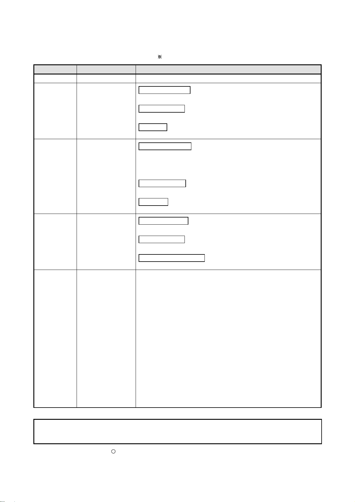
[Test operation precautions]
DANGER
Please read this manual carefully and understand it thoroughly before executing system
monitor, special module mon itor, and cir cuit mo nitor (bit device o n/off, curre nt value ch ange of
word device, setting value of timer/counter and current value change, and current value
change of buffer memory) During test operation, DO NOT change the devices data that are
used to execute important system operations.
Mis-output or mis-operation may cause accidents.
A - 1 A - 1
Page 4
Cautions for using this software
1. Required PC memory
The processing may be terminated by Windows
less than 64M bytes. Make sure to secure the capacity of 64 M bytes or more.
2. Free capacity of hard disk (virtual memory)
At least 50M bytes of free capacity of virtual memory should be secured within hard disk to run this software.
The processing may be terminated by Windows
within hard disk while running GT Designer.
Secure enough free capacity of virtual memory within hard disk space in order to run the software.
When enough free capacity cannot be secured, make sure to save projects frequently.
3. Error messages displayed while starting and editing
“Operation will be terminated because of insufficient memory . Would you like to stop?”
If the above message appears, close other running application software or reboot Windows in order to
secure at least 50M bytes of free hard disk space.
4. GT Designer2 and GOT display
(a) Cautions for displaying straight line other than full line (dotted line, for example) in Bold
When straight line other than full line is drawn in bold, the line may not be displayed with its actual line
width on a personal computer. However, it will be displayed correctly on GOT. This phenomenon
does not mean data problem.
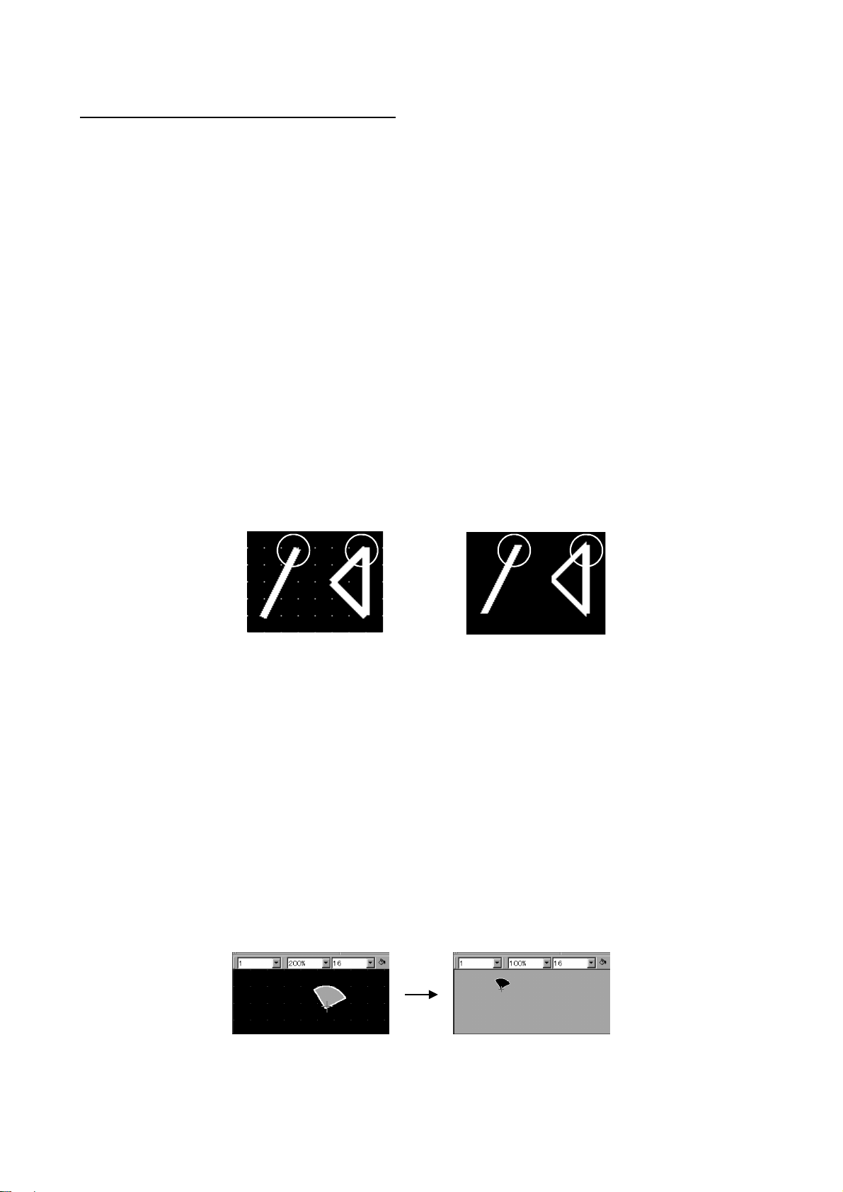
(b) Display of end points of straight line/line freeform/polygon
As shown below, the end points of straight line/line freeform/polygon are displayed differently
between GT Designer2 and GOT.
On GT Designer 2 On GOT
on a personal computer of which main memory capacity is
,
if 50M bytes or more of free space cannot be secured
(c) Start position for filling patterns
Some filling patterns may be differently displayed. For example, the start position may be different
between GT Desginer2 and GOT.
(d) Drawing of different type lines
The length of the dots varies in different dotted lines (for example: the chain lines).
(e) Display of object
The display position of the memory data display in graph function is different between GT Designer2
and GOT.
Even if the display-start-line of a comment has been set, the comment will be displayed from the first
line on GT Designer2.
(f) Display magnification
When display magnification is changed, the connected lines or figures may be separated or the
filled-paint may be out of outline of the figure.
However, if they are displayed correctly on the preview screen, they will appear correctly on GOT as
well.
(Example): When filled-paint is out of the outline.
Display magnification: 200% Display magnification: 100%
Position of Paint mark may be
shifted and the filled-paint may
be out of the figure outline.
A - 2 A - 2
Page 5
5. Restrictions when the color setting is changed to the setting of less colors in the system environment (256
colors
2 colors)
• The color palette for setting color will be changed according to the updated settings.
• The color on the drawing screen will be kept the same as prior to the change.
If the color setting for a [red] rectangle-figure is changed to the 2 colors (B/W), the [red] color will remain.
• The colors of the image data (BMP format file) will be reduced when the project is stored, the screen is
closed and that image data is double-clicked.
6. Object function and device type
he object (bit lamp or word lamp),for which bit device setting and word device setting are separated, cannot
be converted between bit device and word device.
7. When device type is changed
Confirm the device type when the set bit device is changed from bit device into word device.
The device flag may be represented as “??” ,depending on the settings .
(Example) D0. b0
D0 D0.b5 ??
8. OS setting
Set the font size as “Small Font” when setting OS (Windows
) screen.
The GT designer2 dialog box cannot be displayed correctly if the font size is set as “Large font”.
9. When the toolbar icon appears in smaller size after startup of GT Desinger2
The toolbar icon may appear in smaller size right after GT Deseiger2 is started up.
To correctly display the icon, initialize it as instructed below.
(Click on [Project]
[References] from the menu, and select the toolbar tab. Click on Reset All
button in that tab.)
10. When using GT Designer2 in the PC in which the OS other than Japanese version
The text may not be displayed correctly depending on the OS versions; some version include the fonts
incompatible with GT Designer2 or GOT.
A - 3 A - 3
Page 6
REVISIONS
The manual number is given on the left bottom of the back cover.
Print Date Manual Number Revision
Apr., 2003 SH (NA)-080278E-A First edition
Aug., 2003 SH (NA)-080278E-B
Partial corrections
Section 3.2, Section 3.5, Section 4.2, Section 5.4, Chapter 6
Partial additions
Section 5.1.1, Section 6.1.2, Section 6.2.1, Section 6.2.2
Additions
Section 9.5
Jan., 2004 SH (NA)-080278E-C
Partial corrections
Section 1.2, Section 3.1.1, Section 3.4, Section 3.2, Section 3.3.1,
Section 3.4.1, Section 4.3.1, Section 4.7.1, Section 4.8, Section 4.10.1,
Section 4.10.2, Section 5.4, Section 7.1.1, Section 7.3.6, Section 8.1.1,
Section 8.2.6, Section 9.1.1, Section 9.1.2, Appendix 2, Appendix 3.1
Partial additions
Section 2.1.2, Section 5.1.1, Section 8.1.4, Section 9.4
Additions
Section 7.3.7, Section 9.4.2, Section 9.6, Appendix 4
Sep., 2004 SH (NA)-080278E-D
Partial correction
Manuals, Section 5.3, Section 8.1.2
Partial additions
Section 3.1.2, Section 5.3
MODEL CODE change
Changed from 13JU33 to 1DM205
Japanese Manual Version SH-080279-F
This manual confers no industrial property rights or any other kind, nor does it confer any patent licenses. Mitsubishi
Electric Corporation cannot be held responsible for any problems involving industrial property rights which may occur as a
result of using the contents noted in this manual.
c
2003 MITSUBISHI ELECTRIC CORPORATION
A - 4 A - 4
Page 7
Manual Configuration
The following explains the manual configuration
Chapter 1
OVERVIEW
The overview of this manual and features of the GT Designer2
are described.
1
Chapter 2
Chapter 3
Chapter 4
Chapter 5
Chapter 6
Chapter 7
Chapter 8
SYSTEM CONFIGURATION
SCREEN CONFIGURATION
OF GT DESIGNER2
CREATING AND EDITING
SCREEN
DA TA TRANSFER
OPERATION
PRINTING PROJECT/FILE
OUTPUT
USING LIBRARY
DRAW AND EDIT
The system configuration for using the GT Designer2 is
described.
The screen configuration for the GT Designer2 and the screen
customizing m et hod are described.
The operations from the start-up of the GT Designer2 to savi ng
screens are explained.
The explanation on data transfer to the GOT and the transfer
method are described.
The project printing method i s described.
The library utilization method is described.
The drawing of figures and the editing method for objects and
figures are described.
2
3
4
5
6
7
8
Chapter 9
USEFUL FUNCTIONS
The functions useful for drawing are described.
9
A - 5 A - 5
Page 8

INTRODUCTION
Thank you for choosing Mitsubishi Graphic Operation Terminal (Mitsubishi GOT).
Read this m anual and mak e sure you und erstand the f unctions and per formance of the GOT thorou ghly in
advance to ensure correct use.
CONTENTS
SAFETY PR ECAUTIONS A- 1
Cautions for using this software A- 2
REVISIONS A- 4
Manual Configuration A- 5
INTRODUCTION A- 6
CONTENTS A- 6
Function Quick Reference A-11
Manuals A-18
Abbreviation s a n d Ge n e ric Terms in This Ma n u a l A- 19
How to Use T h is Ma n u a l A- 23
1 OVERVIEW 1- 1 to 1- 5
1.1 Overview 1- 1
1.2 Feature 1- 2
2 SYSTEM CONFIGURATION 2- 1 to 2- 6
2.1 System Configuration in Creating Monitor Screen 2- 1
2.1.1 System configuration.....................................................................................................2- 1
2.1.2 Operating environment..................................................................................................2- 1
2.2 System Configuration of Data Transfer and Document Creation 2- 3
2.2.1 System configuration.....................................................................................................2- 3
2.2.2 RS-232C cable to be used............................................................................................2- 5
3 SCREEN CONFIGURATION OF GT DESIGNER2 3- 1 to 3-31
3.1 Screen Configuration and Basic Operation 3- 1
3.1.1 Screen configuration and various tools ........................................................................3- 1
3.1.2 Basic operation of dialog box........................................................................................3- 2
3.1.3 Operation of workspace ................................................................................................3- 4
3.2 Menu Configuration 3- 7
A - 6 A - 6
Page 9

3.3 Toolbars 3- 10
3.3.1 Types of toolbars..........................................................................................................3-10
3.4 Customizing Screen Configuration and Toolbars 3-17
3.4.1 Customizing screen configuration................................................................................3-18
3.4.2 Customizing toolbars....................................................................................................3-20
3.4.3 Customizing GT Designer2 operating environment....................................................3-24
3.4.4 Display with frame ........................................................................................................3-28
3.4.5 Redisplaying drawing screen.......................................................................................3-29
3.5 How to Use Help 3-30
4 CREATING AND EDITING SCREEN 4- 1 to 4-28
4.1 Selecting Project at the Start of GT Designer2 4- 1
4.2 Creating a New Project 4- 2
4.3 Opening/Closing Project 4- 3
4.3.1 Opening project .......................................................................................................... ...4- 3
4.3.2 Closing project...............................................................................................................4- 4
4.4 Providing Title on Project 4- 5
4.5 Creating a New Screen 4- 6
4.6 Opening/Closing Screen 4- 9
4.6.1 Opening screen .............................................................................................................4- 9
4.6.2 Closing screen..............................................................................................................4-12
4.7 Operating Multiple Screens 4-13
4.7.1 Cascading/tiling screens .............................................................................................4- 13
4.7.2 Making editing screen active........................................................................................4-14
4.8 Changing Screen Property 4-15
4.9 Viewing Created Screen Image 4-17
4.10 Copying/Deleting Screen 4-19
4.10.1 Copying screen data .................................................................................................4- 19
4.10.2 Deleting screen data .................................................................................................4- 21
4.11 Setting Screen Switching Device 4-23
4.12 Data Check 4-25
4.13 Saving Project 4-27
4.13.1 Overwriting and saving project..................................................................................4- 27
4.13.2 Saving as project name.............................................................................................4- 27
4.14 Ending GT Designer2 4-28
A - 7 A - 7
Page 10

5 DATA TRANSFER OPERATION 5- 1 to 5-36
5.1 Type and Size of Transfer Data to GOT 5- 1
5.1.1 Data type to be installed on GOT .................................................................................5- 1
5.1.2 Memory space required for data transfer .....................................................................5- 8
5.2 Transferring data with RS-232C cable 5-12
5.2.1 Setting communication.................................................................................................5-15
5.2.2 Getting built-in memory information.............................................................................5-16
5.2.3 Uploading......................................................................................................................5-17
5.2.4 Installing ROM_BIOS ...................................................................................................5-18
5.2.5 Installing OS .................................................................................................................5-21
5.2.6 Downloading monitor data ...........................................................................................5-23
5.2.7 Downloading special data............................................................................................5-25
5.3 Transferring Data Using PC Card 5-26
5.3.1 Installing ROM_BIOS ...................................................................................................5-28
5.3.2 Transferring OS, monitor data and special data .........................................................5-31
5.4 Error Message for Data Transfer 5-34
6. PRINTING PROJECT/FILE OUTPUT 6- 1 to 6-12
6.1 Printing method 6- 1
6.1.1 Setting method...............................................................................................................6- 1
6.1.2 Setting items..................................................................................................................6- 2
6.2 Printing example 6- 7
6.2.1 Printer output .................................................................................................................6- 7
6.2.2 File output .....................................................................................................................6-11
7. USING LIBRARY 7- 1 to 7-16
7.1 What is Library? 7- 1
7.1.1 What you need to know before using library................................................................7- 1
7.1.2 Basic operation of library...............................................................................................7- 3
7.2 Pasting Objects or Figures from Library 7- 5
7.3 Creating Original Library 7- 6
7.3.1 Registering objects or figures on library .......................................................................7- 6
7.3.2 Copying registered library/template..............................................................................7- 7
7.3.3 Deleting registered library/template ..............................................................................7- 8
7.3.4 Editing registered objects and figures...........................................................................7- 9
7.3.5 Changing library property.............................................................................................7-10
7.3.6 Saving library to file ......................................................................................................7-11
7.3.7 Loading library from file................................................................................................7-14
7.4 Utilizing P a n e lk it o f GT Desig n e r 7-16
A - 8 A - 8
Page 11

8. DRAW AND EDIT 8- 1 to 8-26
8.1 Drawing Figures 8- 1
8.1.1 Drawing figures..............................................................................................................8- 1
8.1.2 Entering text...................................................................................................................8- 6
8.1.3 Painting figures..............................................................................................................8- 8
8.1.4 Pasting figure data of BMP/DXF file ............................................................................8-10
8.2 Editing figure and object 8-14
8.2.1 Selecting figure and object...........................................................................................8-14
8.2.2 Editing figures and objects...........................................................................................8-16
8.2.3 Grouping/Ungrouping multiple figures and objects.....................................................8-17
8.2.4 Undo and redo..............................................................................................................8-17
8.2.5 Aligning figures and objects.........................................................................................8-18
8.2.6 Changing attributes of figures and objects..................................................................8-21
8.2.7 Changing size of figures/objects..................................................................................8-23
8.2.8 Copying figures and objects consecutively .................................................................8-25
9. USEFUL FUNCTIONS 9- 1 to 9-31
9.1 Edit Function 9- 1
9.1.1 Batch setting of multiple objects/figures on the same screen(Property sheet) ...........9- 1
9.1.2 Batch setting and managing objects/figures fo r each purpo se(Category workspace).....9- 3
9.1.3 Batch edit ing att rib ut es of ob jec ts /fi gu re s sca tte re d on mul tip le scr ee ns (B at ch e dit ).....9-10
9.1.4 Simple selection of overlapped figure (Data view)......................................................9-14
9.1.5 Checking devices in use (Device list) ..........................................................................9-15
9.2 Referring to Device Comment When Setting Devices 9-16
9.2.1 Importing device comment...........................................................................................9-16
9.2.2 Check method of device comment ..............................................................................9-18
9.3 Checking Monitor Data for Errors 9-20
9.4 Inputting multiple language 9-21
9.4.1 Input method.................................................................................................................9-22
9.4.2 Precautions...................................................................................................................9-25
9.5 Confirming the created data size 9-27
9.5.1 Confirmation method....................................................................................................9-27
9.5.2 Confirmation items........................................................................................................9-27
9.6 Utilizing othe r p r o j e c t d a ta 9-28
9.6.1 Importing data...............................................................................................................9-28
9.6.2 Cautions........................................................................................................................9-29
APPENDIX App- 1 to App-13
Appendix 1 List of Shortcut Keys App- 1
Appendix 2 Q&A of GT Designer2 Operation App- 2
A - 9 A - 9
Page 12

Appendix 3 Using Existing Data App- 5
Appendix 3.1 Outline procedures.......................................................................................App- 5
Appendix 3.2 Precautions ..................................................................................................App- 6
Appendix 4 Applicable Monitor Data App-10
Appendix 4.1 Opening monitor data .................................................................................App-11
Appendix 4.2 Uploading monitor data...............................................................................App-12
Appendix 4.3 Downloading monitor data..........................................................................App-13
Appendix 4.4 Copying monitor data from one GOT unit to other unit with a PC card ....App-13
INDEX Index- 1 to Index- 2
A - 10 A - 10
Page 13
Function Quick Reference
Edit Operation (GT Designer2 Version1 Operating Manual)
Image Function Page
Align
Aligns objects or images Page 8-18
Property sheet
Sets same attributes to objects or images in the same
screen
Page 9-1
Replace c olors
Base 2
Replace shapes
Base 2
Replace devices
M10
Data View
Device list
Base 2
Multiple language input
Base 3
Base 1
Base 3
Base 1
M11 M12
Base 3
Base 1
Base 2
Base 2
M100
D100 Numerical display
D200 ASCII display
D300 Panel meter display
Base 3
Base 1
Base 3
Base 1
M101 M102
Select
Changes the color(s) of the objects and figures
arranged on plural screens at the same time
Changes the switch/lamp figures at the same time Page9-10
Changes the preset devices at the same time Page9-10
Overlapping images or objects Page 9-14
Display the set device in list Page 9-15
Page9-10
Man. Auto
English
Import BMP/DXF file
BMP
file
file
DXF
Import Project
Chinese
Import
Import
Input characters or comments in other language. Page9-21
Imports BMP/DXF files Page8-10
Utilizes other project data Page9-28
A - 11 A - 11
Page 14
A
A
Object Functions (GT Designer2 Version1 Reference Manual)
Digit/font display
Image Function Page
Numerical disp lay
334
D100
D100 : 45
Displays device value in numerical value Page 5-61
Write value on device Page 5-61
Numerical input
D100
D100 : 334
45
Data list
ASCII display
ASCII input
Clock display
D100 : 55
D101 : 122
D102 : 34
D10 : 4241H
D11 : 4443H
A B C D
(BA)
(DC)
02/03/18
15:27
Comment display
RUN STOP
Alarm
larm list
Image Function Page
D100 55
D101 122
D102 34
ABCD
D10 : 4241H
D11 : 4443H
Display multipledevice value in list Page 5-85
Displays device value in text Page 5-100
(BA)
(DC)
Inputs text code device Page 5-100
Displays hour/minutes, year/month/date Page 5-112
Displays command Page 5-118
larm history display
Alarm flow
Alarm
02/04/18 13:25:40
RUN STOP
Time message
13:25 RUN A STOP
13:05 Hight limit over
13:03 Motor trip
Alarm occur
Displays message at alarm occurence Page 5-137
Displays alarm history Page 5-160
Displays alarm in floating Page 5-186
A - 12 A - 12
Page 15
Animation
Parts display
Image Function Page
Display entered device Page 5-191
Part1
Parts movement display
Lamp display
Red
RUN
Panel meter display
Level display
Trend graph display
Line graph display
Blue
STOP
Part2
Displays moving parts Page 5-209
Displays device value via lamp color changing Page 5-238
Displays device data on panel meter Page 5-252
Displays device data in proportional level Page 5-264
Displays device data in trend graph Page 5-276
Bar graph display
Statistics graph display
Scatter graph display
Sampling
Circle graph Bar graph
Displays device data in line graph Page 5-289
Displays device data in bar graph Page 5-301
Displays device data in statistics graph Page 5-313
Displays device data in scatter grap Page 5-323
Collect the device value and edit collected data on PC Page 5-341
A - 13 A - 13
Page 16
Touch switch
Bit switch
Image Function Page
MO : ON OFF
Touch it to switch device ON/OFF Page 5-348
Data write switch
Extended function switch
Screen switching switch
Base 1
Station No.switching switch
Key code switch
Change monitor
destination
A
A B C D
E F G H
D100 :
200 350
Operation
Stop
Base 2
MOV 1 D1
MOV 2 D2
MOV 90 D162
MOV 110 D167
MOV 100 D172
Touch it to change bit device value Page 5-364
K
K
RST V
K
K
K
Touch it to switch to the extended function screen Page 5-369
Touchitto switch between the base and window screen Page 5-377
Touch it to switch the monitored PLC station No. Page 5-387
Used as the key for inputting numerical value/ASCII Page 5-393
Trigger action
Status observation function
Recipe functioin
Time action function
Image Function Page
Write
Write
/Read
D100 : 0 150
D100 : 150
D101 : 300
D102 : 208
Monitors status of device and write value to device or
operates GOT when condition meets
Monitors status of device and write/read device data
when condition meets
Outputs the device writing and sound at specified time. Page 5-430
Page 5-412
Page 5-421
A - 14 A - 14
Page 17
Auxiliary
Test
Image Function Page
Changes device value via test window in monitor
screen
Page 5-437
Script
Set overlay screen
Menu
Security
Offset
Data operation
D100 : 45
Base 3
*****
Numerical value input: D100
200
Write to D110
10
Offset device: D200
180
if(([b:X1]==OFF)&&([b:X2]==OFF)&&([b:X3]==OFF))
{[w:D10]=1;}
if(([b:X1]==ON)&&([b:X2]==OFF)&&([b:X3]==OFF))
{[w:D10]=2;}
if(([b:X1]==OFF)&&([b:X2]==ON)&&([b:X3]==OFF))
{[w:D10]=3;}
if(([b:X1]==OFF)&&([b:X2]==OFF) &&([b:X3]==ON))
{[w:D10]=4;}
Menu
Menu
D100
Base 1
Base 2
180
Controls GOT display by scripts Page 5-440
Set overlay screen from other screens Page 5-451
Restricts the password users Page 5-52
Accumulates the offset device value in monitor device
address and monitor.
Operates device values by expression and enables
objects using the operated value
Page 5-48
Page 5-41
A - 15 A - 15
Page 18
External input/output
Report
Hardcopy
Operation panel
X0
Bar code
Image Function Page
Collects numerical data when condition meets and
prints the numerical data and corresponding code.
Outputs the GOT monitor screen to printer or PC card Page 5-482
Uses operation panel to execute device writing Page 5-488
Page 5-459
1350
Sound
Video
RGB display
Writes data read by barcode reader to device Page 5-496
Outputs sounds Page 5-501
Displays video Page 5-505
Displays PC screens Page 5-523
Data Transmission (GT Designer2 Version1 Operating Manual)
Image Function Page
Download
Transimits monitor screen data from PC to GOT Page 5-1
Upload
Transmits monitor screen data from GOT to PC Page 5-17
A - 16 A - 16
Page 19
Print (GT Designer2 Version1 Operating Manual)
Image Function Page
Print screen
Print base/window/report screen 6-1
Print screen list
Print base/window/report screen 6-1
Print device list
[Bit device]
[X list]
Network device
0-FF X0000 X0001 X0002 ......
X0013 X0016 X0017 ......
1-5 X0050 X0051 X0052 ......
[D list]
O-FF D0.b0
Prints list of the device used 6-1
A - 17 A - 17
Page 20

Manuals
Relevant Manuals
For relevant manuals, refer to the PDF manual stored within the drawing software.
A - 18 A - 18
Page 21
Abbreviations and Generic Terms i n Thi s Manual
Abbreviations and generic terms used in this manual are as follows:
GOT
Abbreviations and generic terms Description
A985GOT-V A985GOT-TBA-V, A985GOT-TBD-V
A985GOT A985GOT-TBA, A985GOT-TBD, A985GOT-TBA-EU
A975GOT-TBA-B, A975GOT-TBD-B, A975GOT-TBA, A975GOT-TBD,
A975GOT-TBA-EU
A970GOT-TBA-B, A970GOT-TBD-B, A970GOT-TBA, A970GOT-TBD,
A970GOT-SBA, A970GOT-SBD, A970GOT-LBA, A970GOT-LBD,
A970GOT-TBA-EU, A970GOT-SBA-EU, A970GOT-LBA-EU
A956GOT-TBD, A956GOT-SBD, A956GOT-LBD,
A956GOT-TBD-M3, A956GOT-SBD-M3, A956GOT-LBD-M3,
A956GOT-SBD-B, A956GOT-SBD-M3-B
A953GOT-TBD, A953GOT-SBD, A953GOT-LBD,
A953GOT-TBD-M3, A953GOT-SBD-M3, A953GOT-LBD-M3,
A953GOT-SBD-B, A953GOT-SBD-M3-B
A951GOT-TBD, A951GOT-SBD, A951GOT-LBD,
A951GOT-TBD-M3, A951GOT-SBD-M3, A951GOT-LBD-M3,
A951GOT-SBD-B, A951GOT-SBD-M3-B
A951GOT-QTBD, A951GOT-QSBD, A951GOT-QLBD,
A951GOT-QTBD-M3, A951GOT-QSBD-M3, A951GOT-QLBD-M3,
A951GOT-QSBD-B, A951GOT-QSBD-M3-B
A950GOT-TBD, A950GOT-SBD, A950GOT-LBD,
A950GOT-TBD-M3, A950GOT-SBD-M3, A950GOT-LBD-M3,
A950GOT-SBD-B, A950GOT-SBD-M3-B
A956GOT, A953GOT, A951GOT, A951GOT-Q,
A950GOT
F940GOT-SBD-H-E, F940GOT-LBD-H-E, F940GOT-SBD-RH-E, F940GOT-LBD-RH-E,
F943GOT-SBD-H-E, F943GOT-LBD-H-E, F943GOT-SBD-RH-E, F943GOT-LBD-RH-E
GOT-A900
series
GOT-F900
series
A975GOT
A970GOT
A97 GOT A975GOT, A970GOT
A960GOT A960GOT-EBA, A960GOT-EBD, A960GOT-EBA-EU
A956WGOT A956WGOT-TBD
A956GOT
A953GOT
A951GOT
A951GOT-Q
A950GOT
A95 handy GOT A950GOT-SBD-M3-H, A950GOT-LBD-M3-H, A953GOT-SBD-M3-H, A953GOT-LBD-M3-H
A95
GOT
F940GOT F940GOT-SWD-E, F940GOT-LWD-E, F943GOT-SWD-E, F943GOT-LWD-E
F930GOT-K F930GOT-BBD-K-E
F930GOT F930GOT-BWD-E, F933GOT-BWD-E
F920GOT-K F920GOT-BBD5-K-E, F920GOT-BBK-E
F940 handy GOT
F940WGOT F940WGOT-TWD-E
Communication board/communication module
Abbreviations and generic terms Description
Communication
board
Communication
module
Bus connection
board
Serial
communication
board
Bus connection
module
Data link module
Network module A7GT-J71LP23, A7GT-J71BR13
CC-Link
communication
module
Ethernet
communication
module
A9GT-QBUSS, A9GT-QBUS2S, A9GT-BUSS, A9GT-BUS2S,
A9GT-50WQBUSS, A9GT-50WBUSS
A9GT-RS4, A9GT-RS2, A9GT-RS2T, A9GT-50WRS2,
A9GT-50WRS4
A9GT-QBUS2SU, A9GT-BUSSU, A9GT-BUS2SU, A7GT-BUSS,
A7GT-BUS2S
A9GT-QJ71LP23, A9GT-QJ71BR13, A7GT-J71AP23, A7GT-J71AR23,
A7GT-J71AT23B
A8GT-J61BT13, A8GT-J61BT15
A9GT-J71E71-T
A - 19 A - 19
Page 22

Option Module
Abbreviations and generic
terms
Option
Module
External I/O
module
Printer interface
module
Memory card
interface module
Video/RGB mixed
input interface
module
Video input
interface module
RGB input
interface module
A9GT-70KBF, A8GT-50KBF
A9GT-50PRF type
A1SD59J-MIF
A9GT-80V4R1
A9GT-80V4
A9GT-80R1
Option
Abbreviations and generic terms Description
A9GT-80LTT, A9GT-70LTTB, A9GT-70LTT, A9GT-70LTS,
A9GT-70LTTBW, A9GT-50LT, F9GT-40LTS, F9GT-30LTB
A9GT-FNB, A9GT-FNB1M, A9GT-FNB2M, A9GT-FNB4M,
A9GT-FNB8M, A9GT-QFNB, A9GT-QFNB4M, A9GT-QFNB8M,
F9GT-40FMB, F9GT-40UMB
A7GT-CNB
A9GT-QCNB
A9GT-80PSC, A9GT-70PSC, A9GT-60PSC, A9GT-50WPSC,
A9GT-50PSC, F9WGT-40PSC, F9GT-40PSC, F9GT-30PSC
Abbreviations o f PC ca r d with JEIDA Ver4.2 ( PC MCIA Ver2.1)
Abbreviation of Compact FlashTM (Compact FlashTM produced by Sun Disk.)
F9GT-HCNB
Option
Backlight
Debug stand A9GT-80STAND, A9GT-70STAND, A9GT-50WSTAND, A9GT-50STAND
Memory board
Ten-key panel A8GT-TK
Bus connector
conversion box
Bus distance
connector box
Protective sheet
Attachment A77GT-96ATT, A85GT-95ATT, A87GT-96ATT, A87GT-97ATT
PC card (memory
card)
Flash PC card A9GTMEM-10M F, A9GTMEM-20MF, A9GTMEM-40MF
Compact Flash
PC card
Connector
conversion box
Software
Abbreviations and generic terms Description
Software
GT Works2
Version1
GT Designer2
Version1
GT Designer2 Abbreviation of GOT900 series graphic software-GT Designer2
GT Simulator2 Abbreviation of GOT900 series screen simulator-GT Simulator2
GT SoftGOT2 Abbreviation of monitoring software-GT SoftGOT2
GT Converter Abbreviation of GOT900 series data conversion software-GT Converter
GX Developer Abbreviation of SW D5C-GPPW(-V)/SW D5F-GPPW(-V) type software package
GX Simulator
DU/WIN Abbreviation of FX-PCS-DU/WIN
SW1D5C-GTWK2-E, SW1D5C-GTWK2-EV
SW1D5C-GTD2-E, SW1D5C-GTD2-EV
Abbreviation of SW
(SW5D5C-LLT(-V) or later)
D5C-LLT(-V) type download test tool function software package
Description
A - 20 A - 20
Page 23
License (for GT SoftGOT, GT SoftGOT2)
Abbreviations and generic
terms
License A9GTSOFT-LKEY-P (for D OS/VPC )
License FD SW5D5F-SGLKEY-J (for PC CPU module)
Description
CPU
Abbreviations and generic
terms
Q00JCPU, Q00CPU, Q01CPU, Q02CPU,
QCPU
QnACPU
ACPU
FXCPU
Motion
controller
CPU
FA controller LM610, LM7600, LM8000
MELDAS C6/C64 FCA C6, FCA C64
QCPU (Q Mode)
QCPU (A Mode) Q02CPU-A, Q02HCPU-A, Q06HCPU-A
QnACPU type
QnASCPU type Q2ASCPU, Q2ASCPU-S1, Q2ASHCPU, Q2ASHCPU-S1
AnUCPU A2UCPU, A2UCPU-S1, A3UCPU, A4UCPU
AnACPU A2ACPU, A2ACPU-S1, A3ACPU
AnNCPU A1NCPU, A2NCPU, A2NCPU-S1, A3NCPU
AnCPU type AnUCPU, AnACPU, AnNCPU
AnUS(H)CPU A2USCPU, A2USCPU-S1, A2USHCPU-S1
AnS(H)CPU
A1SJ(H)CPU A1SJCPU, A1SJCPU-S3, A1SJHCPU
AnSCPU type AnUS(H)CPU, AnS(H)CPU, A1SJ(H)CPU
A1FXCPU A1FXCPU
A0J2HCPU, A2CCPU, A2CCPUC24, A2CJCPU
Motion controller
CPU (A series)
Motion controller
CPU (Q series)
Q02HCPU, Q06HCPU, Q12HCPU, Q25HCPU,
Q12PHCPU, Q25PHCPU
Q2ACPU, Q2ACPU-S1, Q2AHCPU, Q2AHCPU-S1,
Q3ACPU, Q4ACPU, Q4ARCPU
A1SCPU, A1SCPUC24-R2, A2SCPU, A2SCPU-S1,
A1SHCPU, A2SHCPU, A2SHCPU-S1
FX0 series, FXON series, FXOS series, FX 1 series,
FX1N series, FX1NC series, FX1S series, FX2 series,
FX2C series, FX2N series, FX2NC series,
FX(2N)-10GM/20GM series
A273UCPU, A273UHCPU, A273UHCPU-S3,
A373CPU, A373UCPU, A373UCPU-S3,
A171SCPU, A171SCPU-S3, A171SCPU-S3N,
A171SHCPU, A171SHCPUN, A172SHCPU,
A172SHCPUN, A173UHCPU, A173UHCPU-S1
Q172CPU, Q173CPU
Description
A - 21 A - 21
Page 24
Other PLC
Abbreviations and generic terms Description
C200HS, C200H, C200H
C200HE), CQM1, C1000H, C2000H,
Omron PLC
Yaskawa PLC
SLC500 series
AllenBradley
PLC
Sharp PLC
Toshiba
PLC
SIEMENS PLC
HITACHI
PLC
(HIDEC H
series)
Matsushita Electric Works PLC
MicroLogix1000
series
MicroLogix1500
series
PROSEC T
series
PROSEC V
series
Large-sized H
series
H-200 to 252
series
H series board
type
EH-150 series EH-CPU104, EH-CPU208, EH-CPU308, EH-CPU316
CV500, CV1000, CV2000, CVM1-CPU01,
CVM1-CPU11, CVM1-CPU21, CS1, CS1D,
CJ1M, CPM1, CPM1A, CPM2A,
CPM2C, CPM1H
GL60S, GL60H, GL70H, GL120,
GL130, CP-9200SH, CP-9300MS, MP-920,
MP-930, MP-940, MP-9200(H), PROGIC-8
SLC500-20, SLC500-30, SLC500-40, SLC5/01,
SLC5/02, SLC5/03, SLC5/04, SLC5/05
1761-L10BWA, 1761-L10BWB, 1761-L16AWA, 1761-L16BWA,
1761-L16BWB, 1761-L16BBB, 1761-L32AWA, 1761-L32BWA,
1761-L32BWB, 1761-L32BBB, 1761-L32AAA, 1761-L20AWA-5A,
1761-L20BWA-5A, 1761-L20BWB-5A
1764-LSP
JW-21CU, JW-22CU, JW-31CUH, JW-32CUH,
JW-33CUH, JW-50CUH, JW-70CUH, JW-100CUH,
JM-100CU, Z-512J
T3, T3H, T2E, T2N
Model3000, S2T
SIMATIC S7-200 series, SIMATIC S7-300series,
SIMATIC S7-400 series
H-302(CPU2-03H), H-702(CPU2-07H), H-1002(CPU2-10H), H-2002(CPU2-20H),
H-4010(CPU3-40H), H-300(CPU-03Ha), H-700(CPU-07Ha), H-2000(CPU-20Ha)
H-200(CPU-02H,CPE-02H), H-250(CPU21-02H),
H-252(CPU22-02H), H-252B(CPU22-02HB),
H-252C(CPU22-02HC, CPE22-02HC)
H-20DR, H-28DR, H-40DR, H-64DR,
H-20DT, H-28DT, H-40DT, H-64DT,
HL-40DR, HL-64DR
FP0-C16CT, FP0-C32CT, FP1-C24C, FP1-C40C,
FP2, FP2SH, FP2-CCU, FP3,
FP5, FP10(S), FP10SH, FP-M(C20TC),
FP-M(C32TC)
series (C200HX, C200HG,
A - 22 A - 22
Page 25
How to Use This M a nual
Specification of symbols used in this manual
Indicates the operation steps.
Brackets used for the menu and items differ.
[ ] : Refers to menu in menu bar.
Refers to dialog box item or GOT utility
menu.
: Refers to dialog box buttons or PC
keyboard.
Shows functions applicable to GOT-A900 series
(GOT-A900) GOT-F900 series (GOT-F900).
" " , Applicable
" " , N / A
Point
Remark
Shows the items including detailed explanation
(manual and the chapter, section, item).
Refers to information required for
operation.
Refers to information useful for
operation.
Refers to supplementary
explanations.
A - 23 A - 23
Page 26
1. OVERVIEW
1
1.1 Overview
This manual explains the GT Designer2 system configuration, GT Designer2 screen configuration, basic
dialog box operation, creation of new project, data transfer to GOT and convenient operation for screen
editing.
Manuals
Three types of manuals are available for GT Designer2.
Refer to the appropriate manual depenfding on the purpose.
The manuals below are stored in PDF files and included with the product.
Purpose
Install the product into the personal computer
Create a project
Startup • Introductory
Manual
Details
Overview
Reference Manual
Operating Manual
Details
Details
Create screens
Overview
Details
Draw figures
Overview
Details
Make common settings
Overview
Arrange/set objects
Overview
Transfer data to the GOT
Startup & Introductory manual
The product installation method is described.
Examples of simple screen creation and operation on the GOT are described.
Reference Manual
Object/figure/screen specifications and object setting methods are described.
Operating Manual
Screen configuration, screen customizing, and procedures from project creation to data transfer on the
GT Designer2 are described.
1 - 1 1 - 1
Overview
Details
Details
Page 27
1.2 Feature
The GT Designer2 has various functions to improve the drawing efficiency.
Main functions of the GT Designer2 are described below:
1
Easy to know the overall project........................
Settings of the overall project such as created screens or common settings are displayed on the tree.
It is convenient to know the current settings, to check progress of work and to copy the screen.
Section 3.1.3 Operation of
workspace
A screen can be newly
created, copied or deleted.
1 - 2 1 - 2
Page 28
Easy to manage objects for each application ....
The overall project settings are displayed on the tree by category (type).
Classification for each application allows simple management of objects.
Easy to select parts frequently used..................
Objects or figures can be registered and pasted on the screen.
Objects or figures frequently used may be registered as buttons on the toolbar.
Pasting
Item 9.1.2 Managing object/ figure
for each application
Managed for each application.
Chapter 7 Using library
Pasting from toolbar
Simple edit of parts
Part objects or figures once registered can be re-edited with the dedicated editor (library
editor).
Double click
Edit with dedicated editor
1 - 3 1 - 3
Page 29
Shortest setting without opening dialog box......
All setting items and setting details being currently selected are displayed in a list.
Objects and figures can be set without opening the dialog box and the setting details can be checked.
Classifying objects for each application
Since the touch switches are classified for each application, the desired touch switch for setting can
be simply selected. The lamp display function and the part display function are classified into the bit
device and the word device. In this way, the number of setting items is reduced.
Item 9.1.1 Batch setting of multiple
objects/figures on the
same screen
Setting without opening
dialog box
Customizing screen ...........................................
The screen can be customized for the workspace, movement of property sheet or toolbars
display/non-display. You may create figures in the preferred environment.
The dialog box for setting objects may also be customized.
GT Designer2
Movement and display/non-display
of toolbar is available.
Display/non-display for each icon
is also allowed.
Item 3.4.1 Customizing screen
configuration
Dialog box for object setting
Only checked items
are set.
Workspace or property
sheet can be moved.
1 - 4 1 - 4
Page 30
Quick selection of desired screen for editing.....
Double click the screen in the project workspace to display the desired screen for editing.
The screen can be displayed
by double clicking the screen
in the workspace.
Quick selection of desired part for editing..........
Objects or figures set on the screen can be displayed in a list.
If multiple objects or figures are overlapped, it can be simply selected from the data list.
Currently selected objects or figures can also be checked.
Item 4.6.1 Opening screen
Item 9.1.5 Simple selection of
overlapped figure
Real time check of settings in graphic display (view direct)
Setting on the property sheet or the dialog box is quickly displayed on the screen.
Since the screen display can be checked, a screen as you wish can be smoothly created.
Quickly displayed
Quickly displayed
1 - 5 1 - 5
Page 31

2. SYSTEM CONFIGURATION
2.1 System Configuration in Creating Monitor Screen
2.1.1 System configuration
The system configuration of GT Designer2 is shown below:
GT Works2 Version1 or
GT Designer2 Version1
PC
2.1.2 Operating environment
The operating environment of GT Designer2 is shown below:
Item Details
PC PC with PentiumR 200 MHz or more that allows operation of t he OS below.
R
WindowsR 98 operating system
R
WindowsR Millennium Edition operating system
R
WindowsNTR Workstation4.0 operating system 2
R
WindowsR 2000 Professional operating system 2
®
Windows® XP Professional operating system 1 2
®
Windows® XP Home Edition operating syst em 1 2
OS
Microsoft
Microsoft
Microsoft
Microsoft
Microsoft
Microsoft
2
Computer main unit
Hard disk space
Disk drive CD-ROM disk drive
Display color 256 colors
Display Resolution of 800 600 dot s or more
Others Installation of Int ernet Explorer Ver. 5.0 or later is required.
1 "Compatibility mode", "user's easy switching" and "desktop theme (font) change" are not supported.
2 The authority of the administrator is required when installing GT Designer2 into WindowsNTR Workstation4.0,
WindowsR 2000 Professional, WindowsR XP Professional or WindowsR XP Home Edition; when using GT
Designer2 on Windows
CPU
Required memory
R
XP Professional or WindowsR XP Home Edition.
Refer to "Used Operating System and performance required for personal computer main
unit" on the next page.
Installation : 250 MB or more
Operation : 50 MB or more
2 - 1 2 - 1
Page 32

Point
Used Operating System and performance required for personal computer main unit
2
Microsoft® Windows® 98 operating system Pentium® 200MHz or more
Microsoft® Windows® Me operating system Pentium® 200MHz or more
Microsoft® WindowsNT® Workstation 4.0 operating system Pentium® 200MHz or more
Microsoft® Windows® 2000 Professional operating system Pentium® 200MHz or more
Microsoft® Windows® XP Professional operating system
Microsoft
®
Windows® XP Home Edition operating system
Regional Settings of Windows
Depending on the language of your Operating System, this software may not start.
In such a case, start this software after setting the Regional Settings within Control
Panel of Windows
Operating System
R
R
to "English".
Pentium II
control panel
Performance required for personal computer main unit
CPU Required memory
®
300MHz or more
64MB or more
64MB or more
64MB or more
64MB or more
128MB or more
2 - 2 2 - 2
Page 33

2.2 System Configuration of Data Transfer and
Document Creation
2.2.1 System configuration
Using GOT-A900 series
The system configuration using the GOT-A900 series is shown below.
Refer to Section 2.2.2 for the RS-232C cable.
Refer to the GOT user's manual (Details) for the PC card.
POWER
GOT-A900 series
PC
RS-232C cable
The OS program and monitor screen data
can be transferred (written) to the PC card.
PC card in compliance with JEIDA V e r. 4.2
(in compliance with PCMCIA 2.1)
GT Designer2
Printer cable
Printer compatible
with Windows
R
2 - 3 2 - 3
Page 34

Using GOT-F900 series
The system configuration using the GOT-F900 series is shown below.
Refer to Section 2.2.2 for the RS-232C cable.
RS-232C cable
PC
Printer cable
GT Designer2
GOT-F900 s eries
Printe r c omp atible
with Windows
R
2 - 4 2 - 4
Page 35

R
2.2.2 RS-232C cable to be used
The cable type for connection between the PC and the GOT and the connection diagram are shown below.
Using GOT-A900 series
The cable shown below or in the connection diagram is required.
(1) System configuration
PC
1 9-25 pin converter (Diatrend Corp. D232J31) is requi red.
(2) Cable for use
Cable Manufacturer
AC30R2-9SS (9 pin - 9 pin)
FX-232CAB-1 (9 pin - 9 pin)
AC30R2-9P (9 pin - 25 pin)
F2-232CAB-1 (9 pin - 25 pin)
AC30R2-9SS
FX-232CAB-1
AC30R2-9P
F2-232CAB-1
1
1
GOT
Mitsubishi Electri c Corporation
(3) Connection diagram
Use the screw-in type (inch screw) connector for the GOT.
(a) Connection diagram for cables equivalent to AC30R2-9SS and FX-232CAB-1
RXD
TXD
RTS
CTS
DSR
SG
DTR
PC
2
3
7
8
6
5
4
Shield
GOT
2
3
7
8
6
5
4
RXD
TXD
RTS
CTS
DS
SG
DTR
(b) Connection diagram for cables equivalent to AC30R2-9P and F2-232CAB-1
TXD
RXD
RTS
CTS
DSR
SG
DTR
PC
2
3
4
5
6
7
20
Shield
GOT
2
3
7
8
6
5
4
RXD
TXD
RTS
CTS
DSR
SG
DTR
2 - 5 2 - 5
Page 36

Using GOT-F900 series
The cable shown below or in the connection diagram is required.
(1) System configuration
FX-232CAB-1
F2-232CAB-1
PC
GOT
(2) Cable for use
AC30R2-9SS (9 pin - 9 pin)
FX-232CAB-1 (9 pin - 9 pin)
Cable Manufacturer
Mitsubishi Electri c Corporation
(3) Connection diagram
Use the screw-in type (inch screw) connector for the GOT.
(a) Connection diagram for cables equivalent to FX-232CAB-1.
GOT
2
3
7
8
6
5
4
RXD
TXD
RTS
CTS
DSR
SG
DTR
RXD
TXD
RTS
CTS
DSR
SG
DTR
PC
2
3
7
8
6
5
4
Shield
(b) Connection diagram for cables equivalent to F2-232CAB-1.
GOT
2
3
7
8
6
5
4
RXD
TXD
RTS
CTS
DSR
SG
DTR
TXD
RXD
RTS
CTS
DSR
SG
DTR
PC
2
3
4
5
6
7
20
Shield
Point
(1) Cable to be used
The cable for the Version A or later cannot be used.
The RS-232C cable for the Version A or later has the version name at the upper
right of the model on the connector. Check the version.
AC30R2-9SS
A
(2) Cable to be created
Use the F2-232CAB-1 connection cable when the PLC CPU and the GOT are
used at the same time with FX-2PIF by connecting the F940GOT or the
F930GOT to the A series CPU or the FX series CPU through the RS-422 cable.
2 - 6 2 - 6
Page 37

3. SCREEN CONFIGURATION OF
GT DESIGNER2
3.1 Screen Configuration and Basic Operation
3.1.1 Screen configuration and various tools
The screen configuration and various tools are described.
Title bar
Toolbars
All object functions
and figures on the
screen are displayed
in a list.
Created screen
Menu bar
Title bar
Data view
Section 9.1.5
3
Settings on the overall
project such as created
scree n and common
settings are displayed
in tree.
Section 3.1.3
Property sheet Workspace
Attributes of selected
screen, objects and figures
are displayed.
Settings can be made here.
Section 9.1.1
Library image list
Library is displayed.
Objects/figures in library can be
pasted.
Chapter 7
Dropdown menu
Status bar
Part image list
Parts used in the part display
function are displayed.
GT Designer2 Version1
Reference Manual
3 - 1 3 - 1
Page 38

3.1.2 Basic operation of dialog box
3
1) Tab
(3) List box
(5) Text box
(6) Spin box
(7) Radio button
(8) Function list
check box
(4) Check box
(2) Command button
(10) Creation of new folder
(12) Detail
(11) List
(9) To upper level folder
Extension tab
(1) Tab
To switch the tab, click
When the function list check box is
checked, the extension tab is
additionally displayed.
The extension tab allows more
detailed settings than the basic tab.
(2) Command button
Command buttons such as [OK] and
[Cancel] are provided. Click each
button to perform the item.
(3) List box
Click
Click the item for selection.
(4) Check box
To execute an item, click
The settings made on the extension
tab will be ensured even if the
corresponding item is unchecked and
the tab is hidden.
(5) Text box
Input text from the keyboard.
(6) Spin box
Input the value directly or click
to change the value.
(7) Radio button
Click
(8) Function list check box
To display the extension tab, click
to put the
(9) Up One Level
One upper level than the current
folder is displayed.
(10) Create New Folder
A new folder is created.
(11) List
The folders and files which are open
currently are displayed in a list.
(12) Details
Details of the folders and files which
are open currently are displayed.
to display the selection list.
mark.
for the item to be selected.
mark.
.
to put the
(8) Function list check box
When this is checked, the extension tab is additionally displayed.
3 - 2 3 - 2
Page 39

(13) View of table
To select each item, click the left end
of the table.
(13) View of table
3 - 3 3 - 3
Page 40

3.1.3 Operation of workspace
Workspace
The overall project settings are displayed in a tree by data type.
It is easy to manage and edit the overall project data.
Ex. 1) Screen copy
The existing screen is copied using the workspace.
Select the copy source screen and right
click on the mouse to select the [Copy]
menu.
Ex. 2) Part registration
A figure is registered as a part using the workspace.
Drag
Right click the mouse again to select
the [Paste] menu.
When the screen property is set, the
screen is copied.
Select the figure for registration and
drag it to the Parts folder in the
workspace.
When the part number and name are
set, the figure is registered as a part.
3 - 4 3 - 4
Page 41

Workspace type
Types of the workspace are described here.
Project workspace
Overall project settings such as created screens and common settings are displayed in a tree.
It is convenient to see the project details, to check the work progress and to copy a screen.
Set overlay screen
When this is checked,
the set overlay screen
status is displayed in
a tree.
Screen
The created screen is displayed in a tree by type
(base screen, window screen and report screen).
Common settings
The object function settings used in common for the project
are displayed in a tree.
When an item is double clicked, the setting dialog box for
each function is displayed.
Common file
Files of multiple object functions (part, comment and voice)
which are used in common are displayed in a tree.
Set overlay screen
status is displayed
in a tree.
Available functions
• Right click the mouse to select basic commands
such as New Screen, Open or Copy.
Ex.) Right click the window screen.
• Dragging a figure to the project workspace allows
registration of a part.
Ex.) Drag a figure.
Drag
3 - 5 3 - 5
Page 42

Category workspace
The overall project setting is displayed in a tree by category (type).
Classification for each application simplifies management and editing of objects.
Section 9.1.2 Managing and batch changing objects/figures for each application
Library workspace
Objects or figures can be registered and pasted to the screen.
Chapter 7 Using Library
3 - 6 3 - 6
Page 43

3.2 Menu Configuration
Commands assigned to the menu bar are described.
Project
The project menu contains functions of file management, preference
settings and printing.
New creation of project, reading existing files, preference settings and
printing of data being edited are available.
The recent file record can also be displayed.
Edit
View
The edit menu contains edit functions for created figures/objects.
If incorrect operation is done during edit, the screen can be returned
to the previous status. Copy, paste and grouping of objects and
figures are also allowed.
The view menu contains functions of display on the GT Designer2.
Toolbars, status bar, workspace or property sheet can be displayed or
not displayed.
Chapter 8 Draw and edit
Section 3.4.1 Customizing screen configuration
3 - 7 3 - 7
Page 44

Screen
Common
The screen menu contains functions of screen management and
settings in a project.
New screen creation, opening/closing screen and change of window
size are available.
The common settings menu contains functions of common settings.
The object functions used for the overall project can be set.
Comment, part and voice, etc. can also be registered.
Refer to the manual below for details of common settings.
Chapter 4 Creating and editing screen
GT Designer2 Version1 Reference Manual
Figure
The figure menu contains functions of drawing figures.
Various figures can be drawn or figures can be filled. Image data can
also be imported.
Chapter 8 Draw and edit
3 - 8 3 - 8
Page 45

Object
Tools
The object menu contains functions of objects such as lamps or
switches witch are arranged on the screen.
Refer to the manual below for details of each object functions.
The tool menu contains functions of list display of set devices and
error check of setting items.
The data view can be displayed or not displayed.
GT Designer2 Version1 Reference Manual
Chapter 9 Convenient function
Communication
Window
Help
The commands in this chapter is shown for the case of the largest display of the GOT-A900 series. For the
GOT-F900 series, there are some differences for each model, and some models do not display all
commands.
The communication menu contains functions of download, upload,
display of GOT memory information and communication settings.
The window menu contains functions of tiling multiple screens.
The help menu contains functions of viewing the PDF manual related
to the GT Designer2 and checking the software version.
Chapter 5 Data transfer operation
Clause 4.7 Operating multiple screens
Clause 3.6 How to use help
3 - 9 3 - 9
Page 46

3.3 Toolbars
3.3.1 Types of toolbars
The following types of toolbars are available.
When desired toolbars are checked for display/non-display, the toolbars can be displayed/non-displayed
accordingly .
Standard items are displayed as icons.
Display items are displayed as icons.
Figure items are displayed as icons.
Object setting items are displayed as icons.
Figure edit items are displayed as icons.
Align items are displayed as icons.
Draw setting items are displayed as icons.
Communication setting items are displayed as icons.
Report function setting items are displayed as icons.
Favorite toolbars are displayed.
If you drag a displayed toolbar, it may be arranged as a window on the screen.
The following pages also describe details of each toolbar.
3 - 10 3 - 10
Page 47

Main
Name Description
New New project file is created.
Open Existing project file is opened.
Save project E di ting project is overwritten and saved on t he existing file.
New Screen New screen is created.
Open Screen Specified screen is opened.
Cut Figures and obj ects are cut.
Copy Figures and obj ects are copied.
Paste Figures and objects are pasted.
Undo The last operation is cancelled to recover the stat us before change.
Redo The last operation is repeated.
Screen Preview Settings are displayed with the displ ay i mage on the GOT.
Previous Screen Screen with the number before the current screen number is opened.
Next Screen Screen with the number next to the current screen number i s opened.
Unopened Screens
Screen Device List List of devices used is displayed.
Data View All figures and objects arranged on the sc reen are displayed in a list.
Comment Comment to be displayed with the obj ect function is regis tered.
Figure and Object Objection of select i on i s switched to "Figure and Object. "
Unopened screen is opened with "Previous/ Next Screen" in the
ascending/descending order.
3 - 11 3 - 11
Page 48

View
Name Description
Snap Snap movement of the cursor is set .
Zoom Screen display magnifi cation rate/shrinkage rat e i s set.
Grid Interval Grid interval is set.
Grid Color Grid color is set.
ON, OFF Screen is switched to the dis pl ay of device ON/device OFF.
Device, Object ID Device (Dev.) and object ID (ID) are displayed for eac h object.
Screen Color Screen background color is set.
Screen Pattern Screen background pattern i s set.
Screen Background Color Screen background color is set.
Workspace Workspace is displayed.
Property sheet Property sheet is displayed.
3 - 12 3 - 12
Page 49

Figure
Name Description
Line Line is drawn.
Line FreeForm Continuous line is drawn.
Rectangle Rectangle is drawn.
Rectangle (Filled) Filled rectangle is drawn.
Polygon Polygon is drawn.
Circle Circle is drawn.
Circle (Filled) Filled circle is drawn.
Arc Arc is drawn.
Sector Sector i s drawn.
Scale Scale is drawn.
Text Text is input.
Paint Polygon and closed area are painted with the selected pattern.
Import Image BMP format fil e i s imported on the editing s creen.
Import DXF DXF format file is imported on the editi ng screen
3 - 13 3 - 13
Page 50

Object
Switch Touch switch function is set.
Bit Lamp Bit lamp function is set.
Word Lamp Word lamp function is set.
Numerical Display Numerical display function is set.
ASCII Display ASCII display function is set.
Numerical Input Numerical input functi on i s set.
ASCII Input AS CI I input function is set.
Time Display Time display function is set .
Bit Comment Bit comment funct i on i s set.
Name Description
Word Comment Word com ment function is set.
Alarm History Alarm history function is set.
User Alarm Alarm list functi on (User Alarm) is set .
System Alarm Alarm list funct i on (System Alarm ) is set.
Bit Parts Displ a y Bit part s display function is set.
Word Parts Di splay Word parts display function is s et.
Fixed Parts Display Fixed parts display functi on i s set.
Panel meter Panel meter function is set.
Level Level function is set.
Trend Graph Trend graph func tion is set.
Line Graph Line graph function is s et.
Bar graph Bar graph functi on i s set.
3 - 14 3 - 14
Page 51

Edit
Name Description
Bring to Front Selected fi gures and objects are arranged to front.
Bring to Back Select ed f i gures and objects are arranged to back.
Group Selected figures and object s are grouped.
Ungroup Grouping is canceled.
Flip Horizontal Selected figure is flipped horizont al l y.
Flip Vertical Selected figure is flipped vert i cally.
Rotate Left Selected figure is rotat ed 90 degrees to the left.
Rotate Right Selected figure is rotated 90 degrees to the right.
Edit Vortex Length of freeform line or polygon l i ne i s changed.
Align
Align Selected figures and objects are ali gned.
Figure Only figures are selected.
Object Only objects are selected.
Figure and Object Figures and objects are selected.
Name Description
Align Left Aligned with the selected leftmost figure or object.
Align Center (Horizontally) Aligned at the center horizontally.
Align Right Aligned with t he selected rightmos t figure or object.
Align Top Aligned with the selected uppermost figure or object.
Align Center (Vertically) Aligned at the cent er vert ically.
Align Bottom Aligned with the selected lowermost figure or object.
Align Across (Horizontal l y) Selected figures and objects are evenly aligned in the horizontal directi on.
Align Vertical (Vert i cally) Selected figures and objects are evenly aligned i n the vertical direction.
3 - 15 3 - 15
Page 52

Draw
Communication
Name Description
Line Style Li ne style is set or changed.
Line Width Line width is set or changed.
Line/Border Color Line color is set or changed.
Fill Pattern Fill pattern is set or changed.
Pattern Color Fill color is set or changed.
Pattern Background Fill background color is set or c hanged.
Text Color Text color is set or changed.
Text Style Text style is set or changed.
Solid Text Text solid color is set or changed.
Report
Name Description
Communication with GOT Data is transferred to GOT.
Communication with Card Data is t ransferred to PC Card.
Communication Conf i guration Communication setti ng i s made
Name Description
Report Line Report line (Rectangl e) i s drawn.
Report Text Report text is input.
Numerical Print Numerical value for report printing is set.
Bit Comment P ri nt Comment (Bit) for report printing is set.
Word Comment Print Comment (Word) for report printi ng i s set.
Report Repeat Header Header line is set.
Report Repeat Line Repeat line is set.
Selection Report Line Only report lines are selected.
3 - 16 3 - 16
Page 53

3.4 Customizing Screen Configuration and Toolbars
Screen configuration and toolbars can be customized on the GT Designer2 to facilitate operation by
users.
Screen configuration and toolbars customizing methods are described in this section.
Unused toolbars are not displayed.
Size change
Toolbars are displayed
as a wind ow.
Workspace or property sheet is
moved to desired position.
Only toolbar icons necessary
for operation are displayed.
(Unnecessary icons are
not displ ayed.)
3 - 17 3 - 17
Page 54

3.4.1 Customizing screen configuration
Display/non-display of tools, size change and display position change are available.
The areas shown below can be customized.
Toolbars
Data view
Status bar
Workspace
Display/non-display
Click the options in the menu below to display/non-display various tools.
Property sheet
Toolbars
Status bar
Workspace
Property sheet
Library list
Library image list
Part image list
Part image list
Data view
3 - 18 3 - 18
Page 55

Size change
Click the buttons below to change the screen size:
: The selected screen is minimized. : The selected screen is returned to the original size.
(Ex.) Moving or changing size of workspace
: The selected screen is maximized. : The selected screen is closed.
Click
Click .
to pop up the workspace, property sheet and data view.
The workspace pops up as a window.
Change the window size of the workspace.
(Toolbars size cannot be changed.)
When it is dragged to the original position, full
display can be recovered.
A display frame appears
by dragging.
Remark
3 - 19 3 - 19
Customized screen
The GT Designer2 memorizes the customized settings of the screen configuration.
At the next start-up, the previously customized status screen is displayed.
Page 56

3.4.2 Customizing toolbars
Display image of icons can be changed and icons/toolbars can be added or deleted.
(Ex. 1) Deletion of toolbars
(Ex. 2) Addition/deletion of icon
Deletion
(Ex. 3) Movement of icon
(Ex. 4) Icon grouping with partition
Addition
3 - 20 3 - 20
Page 57

Adding or deleting toolbars/icons
Methods of adding or deleting toolbars/icons are shown below:
Select [Project] [Preferences].
The preferences dialog box appears.
Add or delete toolbars/icons with the toolbar tab or the command tab.
Toolbars tab
Toolbars are added or deleted.
Item Description A F
Toolbars Check the desired toolbars for addition. To delete it , remove the check.
Show Tool Tips When the cursor is pl aced on the icon, check t hi s to display the icon nam e.
With Short cut Keys
Reset Only the s el ected toolbars are set to def aul t status.
Reset All All toolbars are set to default status.
When the cursor i s placed on the icon, check this to display the shortcut key. (I t is effective only
when the "Show Tool Tips" is displayed.)
3 - 21 3 - 21
Page 58

Command tab
Icons are added, deleted or moved with the procedures below:
(Ex. 1) Adding icon
Click the desired function for
addition and drag it to the
desired toolbar.
3 - 22 3 - 22
(Ex. 2) Deleting icon
Click the desired icon for
deletion and drag it outside
the toolbar.
Page 59

(Ex. 3) Moving icon
Select the desired icon for
movement and drag it to the
desired position.
When the toolbars are changed, click the Close button.
Deleting icon and inserting partition
While the preferences dialog box is open, select the icon and right click the mouse
to delete icon or to insert partition.
Delete : Delete the selected icon.
Start Group : Insert a partition at the left of the icon.
It is convenient to group with icons.
When all icons at the right of the partition are deleted, the
partition is deleted as well.
3 - 23 3 - 23
Page 60

3.4.3 Customizing GT Designer2 operating environment
Environment for the drawing screen is set.
Select [Project] - [Preferences] menu.
The preferences dialog box appears.
The drawing screen environment is set with operation tab/display tab items.
Operation tab
Operation setting for drawing screen is made.
Item Description A F
Figure/object
deselect-after create
Tool de-select after
use
System setti ng on
new
Change object after
create
Auto File Save
Checked : After arranging object s, the selected st atus (status with handle) is reset.
Not checked : W i t h the selected status (status with handle), figures/objects are arranged on the
drawing screen.
Checked : After setti ng figures/objects, the tool selected status is reset. It i s convenient to
arrange different figures/objects.
Not checked : After setting figures/object s, the selected status remains active. It is convenient to
arrange the same figures/obj ects continuously.
Checked : The system settings dialog box (GOT type, PC type, etc.) appears in creation of a
new project.
Not checked : The system settings dialog box (GOT type, PC type, etc.) does not appear in
creation of a new project.
Checked : After arranging object s on the drawing screen, the settings dialog box automatically
appears.
Not checked : After arranging objects on the drawing screen, the settings dialog box does not
automatically appear.
Checked : File is automatically saved.
Saving interval (5 to 720) is s et.
Not checked : File is not aut omatically saved.
Show "Select
Project" dialog when
you start GT
Designer2
Checked : When the GT Des i gner2 i s started, the project selection dialog box (New, Open,
etc.) appears.
Not checked : W hen t he GT Designer2 is started, the proj ect selection dialog box (New, Open,
etc.) does not appear.
3 - 24 3 - 24
Page 61

Point
(1) Operation in automatic save setting
If the GT Designer2 stops or a power failure occurs in automatic save setting,
the GT Desinger2 shows the dialog box below at the next start-up.
• If a project file is available (a project is saved in the past), this dialog box
When Yes is selected on the dialog box above, the automatically saved file is
recovered.
When either Yes or No is selected, the automatically saved recovery file is
erased.
It is recommended to select Yes and to check that the saved recovery file is
necessary.
(2) Precautions for multiple start of GT Designer2 with automatic save setting
appears when the project file is opened.
• If a project file is not available (no saving after new creation), this dialog
box appears when the GT Designer2 is started.
When automatic save is set, do not perform the following operations.
The message in (1) above appears at the start-up of the 2nd or subsequent GT
Desinger2 and the automatically saved file is then erased.
Reset the automatic save for the following operations:
(a) After new creation, start the 2nd or subsequent GT Designer2 while editing
a project which has not been saved at all.
(b) Open the project which has been opened on the GT Designer2 with the 2nd
or subsequent GT Designer2.
3 - 25 3 - 25
Page 62

View tab
Display for the drawing screen is set.
Item Description A F
Snap 1 Dot value (1, 2, 4, 8 or 16) is selected f or automatic arrangement of figures or objects on the screen.
Position of grid displ ay i s selected.
Position
Grid
Spacing Grid spacing (2 to 64 dots) i s set.
Color Grid display color is selected.
Display items Items displayed on the GT Designer2 are checked.
Paint
Device Thi s item is sele cted to display the device name set in the object .
Object ID
Front : Grid is displayed at the front of the screen.
Back : Grid is displayed at the back of the screen.
None : Grid is not displayed.
When a closed figure is f illed with "Paint ," this item is select ed t o
display the filled st atus.
This item is s el ected to display the object ID of each object.
The object ID is automatically put on each object.
It is convenient to display the object ID in setting the system
information.
Refer to the manual below for details of system inf ormation.
GT Designer2 Version 1 Reference Manual
(Ex.)
Front
(Ex.) Filling in white
(Ex.) x 1000
(Ex.) 10000
Back
(Ex.) Display of level
Object This item is selected to display the s et object.
Refer to the next page for details of
1.
3 - 26 3 - 26
Page 63

1 Snap
Figures and objects are arranged with the dot value set in "Snap."
(Ex.)
Drawing a rectangle ([Snap] is set to 16 dots.)
Determine the start point by clicking. Actual start position
Cursor position
(X=10, Y=12)
It is arranged at the closest position to the
coordinates of multiples of 16. (X=16,
Y=16)
(a) When the end point is determined, the cursor can only moved to the coordinates of
multiples of 16.
(b) When an object display position is determined or a figure is moved, the cursor moves
based on the dot value set in [Snap] as shown above.
(c) One stroke of the
key, key, key and key on the keyboard
moves the cursor in the units of the set dot value.
Set the [Snap] to one dot each and hit
key, key, key and key
each time on the keyboard to move the cursor 1 dot each. This facilitates drawing a fine
figure or position setting.
Display change from toolbars and menu
Items set on the display tab can be changed from toolbars and menu.
(1) Changing drawing screen display from toolbars (display setting)
Change of
ON/OFF status
Display/non-display of
device number
Snap value
Grid spacing
Display magnification
Object ID display/non-display
Grid color
(2) Changing drawing screen display from menu
Display magnification
Display/non-display of device,
object ID, paint and object
Grid display position
Screen background color
3 - 27 3 - 27
Page 64

3.4.4 Display with frame
It is the function to display the outer frame on the drawing screen as if the GOT body frame is imaged.
With this function, a screen can be created with the image of the GOT body.
Standard
Handy
ET
Standard ...... Selectable on all GOT (except F920GOT (128
64)).
(This is not displayed on the GT SoftGOT.)
Handy........... Selectable when the GOT type is set to A95
GOT (320 240) or F94 GOT (320
240).
ET ................ Selectable when the GOT type is set to A94
Keypad......... Selectable when the GOT type is set to A920
GOT (320 240).
GOT (128 64) or A930 GOT (240
80).
Select [View] [Display with Frame] [Standard]/[Handy]/[ET]/[Keypad] menu.
The frame is displayed according to the selected option.
Standard
This function allows an image of the GOT body on the drawing screen.
It is easy to edit a figure at an screen end.
No frame
With frame
Keypad
Handy, ET and Keypad
This function allows an image of the GOT body on the drawing screen.
When a switch or an LED on the body image is clicked, device assignment for the operation switch
LED or the function switch and switch function for the function switch can be set.
It is easy to edit a figure at an screen end.
3 - 28 3 - 28
Page 65

[
.
3.4.5 Redisplaying drawing screen
If paint is used, unpainted areas may occur.
Redisplay provides correct display.
Ex.) Moving an object on paint
Paint
Move an object on pain. The figure shows unpainted areas. Refresh the display with
Select the [View] -> [Redisplay] menu.
Display the drawing screen correctly.
View] [Redisplay] menu
3 - 29 3 - 29
Page 66

3.5 How to use Help
Help is used for referring to the GT Designer2-relevant manual (PDF format) and confirming the
software version.
Point
Operation method
Click on each menu item under [Help].
[Operating Manual] This item is used for referring to GT Desginer2 Version1 operating manual.
[Reference Manual] This item i s used for referring to GT Designer2 Version1 reference manual.
[Index] This item is used for viewing a PDF manual.
[About GTD2…] This item is us ed for confirming the GT Desi gner2 version.
Before viewing PDF format manual
Acrobat Reader must be installed to view PDF format manual
Item Description
[Connect to MELFANSweb…]
PDF manual viewing procedure
(When [Operating Manual]/ [Reference Manual] is selected.)
The selected manual is displayed.
(Refer to the HELP of Acrobat Reader for details of Acrobat Reader operation.)
Manual list is displayed by clicking on INDEX MENU. (
Switches the display to the
first page of the selected item
Returns to INDEX MENU.
This item is used f or connecting to the MITSUBISHI ELECTRIC FA NETW ORK
SERVICE ON WORLD WIDE, ME LFA NS web hom epage
in this section)
3 - 30 3 - 30
Page 67

PDF manual viewing procedure (When [Index] is selected.)
After operating , following screen is displayed. Click on the desired manual.
Click
The selected manual is displayed.
(Refer to the HELP of Acrobat Reader for details of Acrobat Reader operation.)
Switches the display to the
first page of the selected item
Returns to INDEX MENU.
3 - 31 3 - 31
Page 68

4. CREATING AND EDITING SCREEN
4.1 Selecting Project at the Start of GT Designer2
4
At the start of GT Designer2, the project selection dialog box is displayed.
Select whether a project is newly created or existing project data is edited.
From the PC start menu, select [Start] [Program] [MELSOFT Application] [GT Designer2]
to start the GT Designer2.
The project selection dialog box is displayed.
Select
project
Item Description A F
New Click t hi s to create a new project.
Open Click this to edit an exist i ng proj ect data.
Show this dialog
next time you start
GT Designer2
The operation proceeds to the following depending on the items selected.
New : Set [System environment] of a new project.
Open : Specifying a project save source for editing
When you do not want to display this dialog box at the next start of the GT Designer2,
uncheck this.
Section 4.3 Creating a new project
Section 4.4 Opening a project
4 - 1 4 - 1
Page 69

4.2 Creating a New Project
A new project is created.
Perform either of the following operations.
• Click
• Select [Project]
The system environment dialog box appears. Perform the system settings.
For items other than [System settings], refer to the manual below:
(New).
[New] menu.
GT Designer2 Version1 Reference Manual
4
Item Description A F
GOT type The GOT type to be used is set.
The PLC type to be connected is s et .
System
settings
PLC type
Color settings
Point
After system settings, click the OK button to go to operation of New Screen.
Section 4.5 Creating a new screen
Refer to the manual below for details of the PC type.
Screen color displayed on the GOT is set.
Select the color acc ordi ng to the GOT display color.
Change of GOT type
Refer to the manual below for cautions when changing GOT type.
GT Designer2 Version1 Reference Manual
GT Designer2 Version1 Reference Manual
4 - 2 4 - 2
Page 70

4.3 Opening/Closing Project
4.3.1 Opening project
A saved project data is read from the project save source.
Perform either of the following operations.
• Click
(Open).
• Select [Project]
[Open] menu.
The open dialog box is displayed.
Item Description A F
Look in Selec t the location where the project is saved.
File name Set the project name for opening.
Select the type of project for opening.
Files of type
GTD file (
DU-Win file (
GOT file (
.GTD) : Project data of GT Designer2 is opened.
.DUP) : Project data of DU-Win is opened.
.GOT) : Project data of GT Designer is opened.
Remark
(1) Using existing GOT data
• GOT800 series : The data are converted to the monitor screen data for
the GOT-A900 series with the GT converter.
• A77GOT and 64GOT : The data are converted to the monitor data for the
GOT-A800 series and then converted to the monitor
screen data for the GOT-A900 series with the GT
converter.
Refer to the following for conversion to the monitor screen data for the
GOT-A900 series.
GT Converter Help function
4 - 3 4 - 3
Page 71

Click the Open button to open the specified project.
(2) Using existing DU (data access unit) data
• DU series: Select the DU-WIN file and open the project data.
The DU-WIN file is the project data prepared with the FX-PCS-DU/WIN
drawing software.
Up to Ver. 1.01B, a temporary file is created in the some folder of DU-WIN file in
reading.
Accordingly, a write-enabled memory device (such as folppy disk and hard disk)
should be set to the write-enabled status.
The read screen data is compatible because the menu name and data handling
of the software DU-WIN are same.
• The base screen No. starts from No.0.
• The system information consists of control devices.
For the details, refer to the GOT-F900 SERIES OPERATION MANUAL (GT
Designer2 Version1).
Remark
Opening project directly
Double click the project data (
data open.
4.3.2 Closing project
Close the open project.
Select [Project] [Close] menu.
The open project data is closed.
.GTD). The GT Designer2 starts with the project
4 - 4 4 - 4
Page 72

4.4 Providing Title on Project
Detailed information (project ID, detailed explanation, author, etc.) for the project is set.
Select [Common settings] [System environment] from the menu.
Double click [Project title] of the system environment.
The project title dialog box appears.
Set the following items and click the OK button.
Item Description A F
Project title
Project ID 1 Set the ID in the range of 1 to 4294967295.
Detailed Explanation
Author
Project title is set as required.
Set the text within 32 characters.
Project is explained as required.
Set the text within 512 characters.
(If a line feed is used, i t is considered as 2 charac ters.)
Author name is set as required.
Set the text within 8 characters.
Refer to the following for details of
1.
1 Project ID
The project ID number is registered to prevent the downloaded project data from being mixed with other
project data.
When a part of the other project data screen is downloaded, the project ID number is checked to call
your attention.
(If the project ID number is different, the data can be downloaded.)
4 - 5 4 - 5
Page 73

4.5 Creating a New Screen
Base screen, window screen and report screen are newly created.
Refer to the manual below for the preparation method of the report screen.
Perform either of the following operations.
GT Designer2 Version1 Reference Manual
• Click
(New Screen).
• Select [Screen]
[New Screen] [Base Screen]/[Window Screen] menu.
The screen property dialog box is displayed.
After setting the items below, click the OK button. The screen is created.
Basic tab
Screen number, name and type of the new screen are set.
Item Description A F
Screen Number Screen number is s el ected.
Screen Name
Screen Type
Security
(GOT-A900 series) (GOT-F900 series)
Screen name is input.
Set the text within 32 characters.
(If a line feed is used, i t is considered as 2 charac ters.)
Screen type is selected.
Base screen : Base screen is creat ed.
Window screen: Wi ndow sc reen i s created.
Security level (1 to 15) of each screen is set.
When the securi t y f unction is not used, s et to "0."
Refer to the manual below for details of the security func t i on.
GT Designer2 Version1 Reference Manual
4 - 6 4 - 6
Page 74

Item Description A F
Detailed Explanation
Use screen color
Pattern
Foreground
Background
Background Color of the overall screen is set.
Screen Size 1
Explanation of the new screen to be created is i nput as required.
512 characters can be input.
Color of the overall screen is set.
Pattern type is displayed with f i l l ed color on the background.
(Ex.) Background :
Pattern :
Foreground :
Size is displayed only for c reation of the window screen.
Size of the window screen is set.
Pattern type + Filled color
Background
Refer to the following for details of
1.
1 Screen size
Set the following items to determine the window screen size.
Item Description A F
X Horizontal window screen size is set.
Y Vertical window screen size i s set.
A handle for size change is displayed on the screen. Move the cursor to the handle position
and drag it to change the size.
Edit
When the screen becomes the desired si ze, click it to determine the window screen size.
This cannot be set when the screen is newly creat ed.
(This can be selected for editing after creation of the screen.)
4 - 7 4 - 7
Page 75

Auxiliary setting tab
Settings of the cursor, key window or data input for the screen which is newly created, and
use/non-use of some object functions are specified.
Settings here can be changed after creation of the screen.
Refer to the manual below for details of the settings.
GT Designer2 Version1 Reference Manual
Key window tab
The key window which is used on the new screen is set.
Settings here can be changed after creation of the screen.
Refer to the manual below for details of the settings.
GT Designer2 Version1 Reference Manual
4 - 8 4 - 8
Page 76

4.6 Opening/Closing Screen
4.6.1 Opening screen
Point
Screen data are imported on the currently editing project.
The procedures are as follows:
(1) Open the screen from the workspace.
(Operation details are described on the
following pages.)
Number of screens that can be opened at a time
Maximum 25 screens can be opened.
(2) Open the screen from the menu.
(Operation details are described in Hint on
the following pages.)
(3) Open the screen continuously.
(Operation details are described in Hint on the
following pages.)
4 - 9 4 - 9
Page 77

In this section, the method of opening the screen from the workspace in (1) is described.
Double click the desired screen for opening in the project workspace.
Double click
The screen opens.
Method of opening other than workspace
(1) Opening screen from menu
Perform either of the following operations.
• Click
(Open) of toolbars (Standard).
• Select [Screen]
[Open] from the menu.
The dialog box to open the screen is displayed.
Click the Image button.
(Double click the desired screen directly for opening.)
4 - 10 4 - 10
Page 78

The screen image view dialog box is displayed.
Double click the desired screen.
Item Description A F
Screen type for opening is selec ted.
Screen Type
Screen display list
Jump The screen number is selected to open the screen.
Base screen : Base sc reen i s displayed.
Window screen: Window screen is displayed.
Report screen : Report screen is displayed.
Screen image is dis pl ayed i n a l i st.
Double click each sc reen to open the screen.
(2) Opening screen continuously
Select the drawing screen of the desired type (base screen/window screen)
for continuous opening and make the screen active.
Click of the toolbars and keep the button depressed (
Click the button to open the same type screen of the active
screen.
).
4 - 11 4 - 11
Page 79

4.6.2 Closing screen
The open screen is closed.
Perform either of the following operations.
• Select [Screen]
• Click
The open screen is closed.
on the title bar of each screen.
[Close] from the menu.
Closing all screens.
Select [Screen]
[Close All] from the menu to close all open screens.
4 - 12 4 - 12
Page 80

4.7 Operating Multiple Screens
4.7.1 Cascading/tiling screens
Multiple screens in the project are reordered.
Select [Window] [Cascade]/[Tile Vertical]/[Tile Horiz ontal].
Multiple open screens are reordered as follows:
(Ex.)
• Cascade
Overlapped screens are displayed toward the lower right like a staircase.
• Tile vertical
Screens are displayed as follows without overlapping.
• Tile horizontal
Screens are displayed as follows without overlapping.
4 - 13 4 - 13
Page 81

4.7.2 Making editing screen active
To edit a screen while multiple screens are displayed, make the edit screen active with either of the
methods below:
Select the screen name from the [Window] menu.
(Ex.)
Click on a part of the screen.
Click on a part of the screen to make it active.
(Ex.)
W-1: Key window switch
Screen name
Screen type and number
(B: Base screen, W: Window screen,
R: Report screen)
Click
Click on a part of the left window.
Remark
Activating method with
of toolbar
The left window is displayed at the front.
Click
of the toolbar to switch the active screen within a range of the
same screen type (base/window screen/report screen).
4 - 14 4 - 14
Page 82

4.8 Changing Screen Property
Screen settings such as screen number or home are changed.
Select the desired screen to change the property in the project workspace and select [Property] by
right clicking on the mouse.
The screen property dialog box appears.
Refer to the following for details of settings.
Section 4.5 Creating a new screen
Basic tab
The screen number or name is changed.
4 - 15 4 - 15
Page 83

Auxiliary setting tab
Settings for data input operation and use/non-use of the object function are changed on the
setting screen.
Key window tab
Settings for key window used on the setting screen are changed.
After changing settings of each tab, click the OK button.
4 - 16 4 - 16
Page 84

4.9 Viewing Created Screen Image
Image displayed on the GOT is checked.
Perform either of the following operations.
• Click
• Select [View]
The image displayed on the GOT is displayed on the preview screen.
The preview display can be changed/output from each menu.
.
[Preview] menu.
File
View
Item Description A F
Save Preview display is saved in a file (BMP format file).
Print Preview display is printed.
Printer Settings Printer settings, paper and paper orientation are set.
Output in
reverse
Fill Black at
Text BG
Dithering
Close Preview screen is cl osed.
Menu and Title Display/non-display of the title bar is selec ted.
Toolbar Display/non-di splay of the toolbars is selected.
Status Bar Display/non-display of the status bar is selected.
Black and white is reversed when printing based on the printer/file sett i ng.
Letters are filled in white and letter background is filled in black to make clearly visible
reversed when printing based on the printer/fil e setting.
Intermediate color t one i s provided on the two tone monochrome screen when printing
based on the printer/file setting.
4 - 17 4 - 17
Page 85

Item Description A F
Display
ON Image
Next State Screen display status set with t he "State" in the object i s switched in the ascending order.
Previous State Screen dis pl ay status set with the "S tate" in the object is switched in the descending order.
2 Colors (EL)
2 Colors (Blue
Back)
2 Colors
(Monochrome)
8 Colors
16 Colors
256 Colors
Every time the menu is selected, the preview screen display is switched to ON/OFF status.
The display is the same as the ON/OFF display on the drawing screen.
Screen colors to be displ ayed are set.
Select the colors avail abl e f or the GOT to be used.
Remark
(1) Items displayed on preview
Items displayed on the preview (display/non-display of object, object ID, device
name, etc.) can be changed with the settings of the GT Designer2.
Section 3.4.3 Customizing GT Designer2 operating environment
(2) Display of object ID and device name
Object ID and device name are displayed on the preview screen. It is not
displayed on the GOT.
Object ID
Device name
4 - 18 4 - 18
Page 86

4.10 Copying/Deleting Screen
4.10.1 Copying screen data
Select the desired screen for copying in the project workspace and right click the mouse to select the
[Copy] menu. Up to 25 screens can be copied at a time.
Right click
Right click the mouse again and select the [Paste].
The screen property dialog box appears. Set the screen number of the copying screen.
After setting, click the OK button to display the copied screen.
Section 4.5 Creating a new screen
4 - 19 4 - 19
Page 87

Remark
To copy screens continuously
One screen can be copied to multiple screens.
Select [Screen] [Utilize].
The utilize dialog box appears.
Set the following items and click the Copy button.
Item Description A F
Project display list The screen to be copied is selected (up to 25 screens ).
Destination Set the copy destination screen number (1 to 32767).
The number of copies is s et.
Up to 100 screens can be copied at a time.
Ex.: Copying with destination number " 6" and number of
copy "3"
The screen is copied to base s creens 6, 7 and 8.
Copy Number
Before copy After copy
The screen is copied.
Property (name, attribute, etc.) of the copied screen is checked or edited.
Section 4.5 Creating a new screen
4 - 20 4 - 20
Page 88

4.10.2 Deleting screen data
Select the desired screen for deletion in the workspace (project tab) and right click the mouse to
select the [Delete] menu.
Right click
The confirmation screen for deletion of the screen appears. Click the Yes button.
The selected screen is deleted.
4 - 21 4 - 21
Page 89

Remark
Deleting screen data from menu bar
Select [Screen] [Delete] menu.
The screen deletion dialog box appears.
Select the screen to be deleted and click the Delete button.
The selected screen is deleted.
4 - 22 4 - 22
Page 90

4.11 Setting Screen Switching Device
To switch the screen on the GOT or to display the window screen, use the dedicated device for screen
switching.
Refer to the manual below for details of the screen switching device.
Select [Common] [System Environment] menu of the menu bar.
Double click [Screen Switching] of the system environment.
The screen switching setting dialog box appears.
After setting, click the OK button.
GT Designer2 Version1 Reference Manual
(Setting of GOT-A900 series)
4 - 23 4 - 23
(Setting of GOT-F900 series)
Page 91

Base Screen
Item Description A F
The base screen switching device is set.
Refer to the manual below for the devic e setting method.
GT Designer2 Version1 Reference Manual
Overlap Window 1
Overlap Window 2
Display Position
Superimpose Window
Uninitialize switching sc reen
device
is specified with
the device
Window bar
None
Remark
This is checked to di splay overlap window 1 and overlap window 2.
After checking, the screen switching device of each window is set.
(When the screen switching device is not set, the window for that type is not displ ayed. )
This is checked to specify the window display position with the device value.
This is checked not to display the movem ent key and the close key.
This is checked to di splay the superimpose window.
After checking, t he screen switching device of t he super impose window is set.
(When the screen switching device is not set, the superimpose window is not displayed.)
When "1" is t o be i nput to the device set in Base screen at power ON, this is unc hecked.
The device value is reset when the PLC is powered ON and it prevents the screen data
error from being displayed on the GOT screen.
(1) Setting in project workspace
Double click the system environment. The system environment setting dialog
box appears. Double click [Screen Switching].
Double click
(2) What is the screen switching device?
To switch a screen on the GOT or to display the window screen, use the screen
switching device.
The GOT displays the screen for the value stored in the screen switching
device.
Use the device set for the screen switching only for screen switching on the
GOT.
When the screen switching device value is "1,"
the GOT displays base screen 1.
D100 1
When the screen switching device value is "1 --> 3,"
the GOT displays base screen 3.
D100 3
Base screen1 Base screen3 Base screen2Base screen1 Base screen3
Base screen2
4 - 24 4 - 24
Page 92

4.12 Data Check
Whether the monitor screen data created with the GT Designer2 has an error or not is checked.
Open all screens for data check. Unopened screens are not data checked.
Select [Tools] [Data Check] menu.
The data check dialog box is displayed.
Set the check items for data check and click the Check button.
Check Item Items for data check are checked.
Touch Area
Key Count Whether the num ber of touch switch functions exceeds 256 on one screen is check ed.
Scroll Object
Report Data
(Setting of GOT-A900 series) (Setting of GOT-F900 series)
Item Description
Whether overlap of touch switch functions occurs is check ed.
• Touch switches are overlapped.
• Numerical input/ASCII input is overlapped with touc h switches.
Memory Store
Object
Window Screen
Data
Number of
object entries
Nest level of set
overlay screens
Whether the num ber of objects (alarm li st, trend graph and scatter graph) which set the
memory storage is 17 or more for each object is checked.
Whether the data li st or the alarm history i s set on the window screen is check ed. (The
data list and the alarm hi story cannot be displayed on the window screen.)
Whether mul t iple objects with scroll di splay (data list, alarm history and alarm list) are set
on one screen is checked.
When the report sc reen i s created, whether the numerical pri nt or the comment pri nt is set
on the header is checked.
Whether the num ber of objects that can be registered on one screen exceeds the limit is
checked.
Whether the nest l evel of set overlay screens is withi n 5 t hat can be set on one screen is
checked.
A F
Data Area Whether any obj ect is set outsi de t he screen range is checked.
Carry out Checking during
save or transfer
Key window
screen data
Whether there is any obj ect that cannot be set on the window screen is checked.
Data check is automatically performed when a project i s saved or a monitor sc reen dat a i s
transferred to the GOT.
4 - 25 4 - 25
Page 93

Remark
When the data check is performed with the settings, click the Check button.
(To close the dialog box after updating the settings, click the OK button.)
If an error is detected after checking, the following screen is displayed.
(Ex.)
When OK is clicked, data check is continued for any other error.
When Abort is clicked, data check is cancelled.
Applicable item for data check
Data check are applicable only for open screens.
Closed screens are not checked.
4 - 26 4 - 26
Page 94

4.13 Saving Project
4.13.1 Overwriting and saving project
When an existing data has been edited, the project is overwritten and saved.
Perform either of the following operations.
• Click
• Select [Project]
Point
4.13.2 Saving as project name
When a newly created project is saved or an existing project is saved with a different project name, set
as follows:
Select [Project] [Save as].
The save as dialog box appears.
Set the following items and click the Save button.
(Overwrite).
[Save] menu.
When using FD (floppy disk).
When a project is overwritten and saved, the same size of free disk space as the
project data size is required. If an FD is used, overwriting and saving may not be
carried out due to insufficient disk space.
If overwriting and saving is not allowed, save the project in the PC hard disk. Then,
copy it to the FD.
Item Description A F
Save in The location to save the project is selected.
File name The project name to be saved is set.
Save as type
GT Designer2 Files (
It is saved as the GT Desi gner2 format project data.
Intel Hex Files (
It is the data transf er data file between the ROM writer and the PC and is
saved as the Intel Hex code.
Data cannot be saved in other formats (GT Designer, DU-WIN).
.GTD)
.ITH) (only for GOT-F900 series)
4 - 27 4 - 27
Page 95

Point
When an existing project is saved as a different project
The library data (GTD2.ldb) with registration of user-created objects and figures are
not saved as a different project file.
The project saved as a different project refers to the same library data (GTD2.ldb)
as the existing project.
If you want to separate a library from the existing project data, save the existing
project library as a different file.
Item 7.3.6 Saving library into file
4.14 Ending GT Designer2
Select [Project] [Exit].
The GT Designer2 is ended.
Remark
Ending GT Designer2 from title bar
Click
on the title bar to end the GT Designer2.
4 - 28 4 - 28
Page 96

5. DATA TRANSFER OPERATION
5.1 Type and Size of Transfer Data to GOT
5.1.1 Data type to be installed on GOT
5
To operate the GOT, it is necessary to transfer the following data to the GOT.
(In the GOT-F900 Series, as the data including the OS has been written prior to shipment, the data
transfer is not necessary.)
Item
ROM_BIOS Dedicated memory
Standard monitor OS Dedicated memory
OS
Monitor data (Provided by user) Built-in memory
Special data
(special module/motion/
servo amplifier m oni tor data)
: Data must be transferred.
: Data needs to be transferred depending on the function.
1 Transfer destination
Dedicated memory: Area to store the ROM_BIOS, standard monitor OS and communication driver.
Built-in memory: Area to store the extended function OS, monitor data and special data.
Communication dri ver Dedicated memory
Extended function OS Built-in m emory
Calculation or addition of the memory space is not required.
Calculation of the memory space and addition of the memory is required as
necessary.
Point
(1) Downloading monitor data
When the version of the ROM_BIOS and the OS (standard monitor OS,
communication driver and extended function OS) of the GT Designer2 is later than
that of the system program installed on the GOT, the new functions may not be
compatible.
It is recommended to reinstall the ROM_BIOS and the OS when downloading the
monitor data to the GOT.
(2) Installing OS
Make sure that the version numbers (leftmost version) of the OS (standard monitor
OS, communication driver and extended function OS) are the same.
If the version numbers are different, the GOT is not operated.
(Ex. 1) (Ex. 2)
Transfer destination 1
(Area in GOT)
Built-in memory
Standard monitor OS : Ver. 9. .
Communication driver : Ver. 9. .
Extended function OS : Ver. 9. .
The GOT is operated.
Necessity Reference A F
Standard monitor OS : Ver. 9. .
Communication driver : Ver. 8. .
Extended function OS : Ver. 8. .
The GOT is not operated.
in this section
in this section
in this section
in this section
in this section
in this section
5 - 1 5 - 1
Page 97

n
ROM_BIOS
It is the data required for control of the GOT hardware and communication between the PC and the
GOT.
The ROM_BIOS is installed prior to shipment of the GOT.
To use the following types/functions, the ROM_BIOS of the applicable version needs to be installed to
the GOT.
Use of flash PC card Version F or later
Type/function name Applicable ROM_BIOS version
MELSEC-Q/QnA ladder monitor function Version H or later
A9GT-QFNB8M
A9GT-FNB8M
A9GT-FNB1M (Hardware version B or later)
A9GT-FNB2M (Hardware version B or later)
A9GT-FNB4M (Hardware version B or later)
A9GT-QFNB (Hardware version B or later)
Use of base screen numbers from 1024 to 4096 Version P or later
Ethernet connection Version Q or later
Gateway function Version S or later
CNC monitor function
KANA KANJI func tion
Font change function V ersion X or later
Version H or later
Version M or later
Version W or later
5
(1) Check method of ROM_BIOS
The ROM_BIOS version installed to the GOT can be checked with the GOT memory
information or the rating nameplate.
If a user has upgraded the ROM_BIOS, the ROM_BIOS version installed on the GOT is
different from the version on the rating nameplate. Check the version from the memory
information.
Immediately after purchase of the product, the version may be checked with the rating
nameplate.
(a) Memory information (b) Rating nameplate
MEMORY INFORMATION
[ S/W Version ]
ROM BIOS Ver.8.0.1 [M]
SYSTEM Ver.8.0.1
COMM. DRIVER Ver.8.0.1
PLC MONITOR Ver.8.0.1
ESC PRINT.B-CODE Not Installed
LADDER (A) Ver.8.0.1
SP. UNIT MON Ver.8.0.1
(SP,RECIPE,WAVE)
SP. UNIT DATA Not Installed
NET WORK MON Ver.8.0.1
(M)
ROM_BIOS Version
GRAPHIC OPERATION TERMINAL
MODEL A970GOT-TBA
IN 100-240VAC 50/60Hz
POWER MAX 115VA
LISTED 80M1
MITSUBISHI ELECTRIC CORPORATION
MADE IN JAPAN
IND. CONT . EQ.
DATE 0010 A M
A
BD992C091H01
A M
ROM_BIOS Versio
5 - 2 5 - 2
Page 98

Remark
Display method of memory information
Display the GOT memory information on the utility.
<Display example of memory information>
Touch the upper right
and the upper left of the
screen at the same time.
Select the utility memory
information.
Refer to the manual below for the start-up method and the operation method of the
utility.
GOT-A900 Series Operating Manual (GT Works2 Version1/GT Designer2
Version1 compatible Extended • Option Functions Manual)
(2) Upgrading method
The ROM_BIOS can be upgraded with the method below:
(a) Upgrading with RS-232C communication
Section 5.2 Transferring data with RS-232C communication
(b) Upgrading with PC card
Section 5.3 Transferring data with PC card
Standard monitor OS
It is the program to control the monitor function.
5 - 3 5 - 3
Page 99

Communication driver
It is the driver to make communication between the GOT and the PLC CPU.
Select the communication driver suitable for the connection type.
Connection type Communication driver name
Bus connection
CPU direct connection
Computer link
connection
MELSECNET
connection
CC-Link connection
Ethernet connection QJ71E71/AJ71(Q)E71
QCPU (Q mode) Bus (Q)
A/QnACPU Bus (A/QnA)
A/QnA/QCPU, MELDAS C6/C64 A/QnA/ QCPU, QJ71C24, MELDAS C6*
FXCPU MELSEC-FX
QCPU A/QnA/QCPU, QJ71C24, MELDAS C6*
QnACPU AJ71QC24
QCPU (A mode), ACPU AJ71C24/UC24
Data link system MNET2/B
MNET/10 (A/QnA/Q)
Network system
MNET/10 (A)
Remote device stat i on CC-LINK(RD)
Intelligent device station CC-LINK (ID)
Through G4 CC-LINK(G4)
OMRON PLC connection OMRON SYSMAC
YASKAWA PLC Connection YASKAWA GL/CP9200 (SH/H)/CP9300MS S eri es
Microcomputer connect i on Microcomputer connect i on
Allen-Bradley PLC connecti on
SHARP PLC connection SHARP JW
TOSHIBA PLC connection TOSHIBA PROSEC T/V
SIEMENS PLC connecti on SIEMENS S7-300/400
HITACHI PLC connection
MATSUSHITA Electric Works PLC connec tion MATSUSHITA MEWNE T-FP
AB SLC500, AB1: N connec tion
AB Micrologix
HITACHI HIDIC H
HITACHI H (Protocol 2)
Refer to the manual below for details of the connection type.
GOT-A900 Series Users Manual (GT Works2 Version1/GT Designer2 Version1
compatible Connection System Manual)
5 - 4 5 - 4
Page 100

Extended function OS
It is the program to use the following functions on the GOT.
• Ladder monitor function • System monitor function • Special function module function
• Network monitor function • List editor function • Gateway function
• Motion monitor function • Servo amplifier monitor function • CNC monitor function
• KANA KANJI function
1 • Recipe function • Sound function
• Bar code function • Report function • Operation panel function
• Hard copy function • Printer output
• Creating CSV format file with alarm history function or/and recipe function
1 This function is dedicated to Japanese version.
(1) Combination of extended function OS that can be installed
The extended function OS is installed in the built-in memory of the GOT.
The extended function OS can be installed up to 6 in total equivalent to the number of required
memories.
Either one of "ladder monitor", "motion monitor/CNC monitor" and "other" extended function
OS can be installed.
Extended function OS name
System monit or 1
Ladder monitor for MESELC-A 1
Ladder
monitor
Motion monitor 1 2
CNC monitor 1 2
Special unit, recipe, sound 1
Network monitor 1
List editor function for MESELC-A 1 2
Gateway (Server, client, mail , FTP) 1 2
Servo amplifier monitor 1 2
KANA KANJI (JPN) 1 2
Others 2
1: When the num ber of required memories installed on the GOT is 4 or less, the OS may not be inst al led.
If the OS cannot be inst all ed, delete all extended function OS ins t al l ed on the GOT and then reinstall the extended
function OS again.
2: Select "Other" extended func t i on OS referring to Point on the next page.
Ladder monitor for MESELC-QnA 1 2
Ladder monitor for MESELC-Q 1 2
Ladder monitor for MESELC-FX 1
ESC printer, bar code, report, CSV, keyboard 1
PCL printer, bar code, report, CS V, keyboard 1
ESC printer, bar code, report, CSV, I/O 1
PCL printer, bar code, report, CS V, I/O 1
ESC printer, bar code, report, CSV, video/RGB 1
PCL printer, bar code, report, CS V, video/RGB 1
Chinese (Big 5) printer, bar code, report, CSV, keyboard 1
Chinese (Big 5) printer, bar code, report, CSV, I/O 1
Chinese (Big 5) printer, bar code, report , CSV, video/RGB 1
Chinese (GB) printer, bar code, report , CSV, keyboard 1
Chinese (GB) printer, bar code, report , CSV, I/O 1
Chinese (GB) printer, bar code, report , CSV, video/RGB 1
Number of required
memories at installation
Remark
Only one
can be
installed.
Only one
can be
installed.
Only one
can be
installed.
5 - 5 5 - 5
 Loading...