

Page 1

MELSEC iQ-R High Speed Data Logger Module
User's Manual (Startup)
-RD81DL96
-SW1DNN-RDLUTL (High Speed Data Logger Module Tool)
Page 2

Page 3
SAFETY PRECAUTIONS
WARNING
Indicates that incorrect handling may cause hazardous conditions, resulting in
death or severe injury.
CAUTION
Indicates that incorrect handling may cause hazardous conditions, resulting in
minor or moderate injury or property damage.
(Read these precautions before using this product.)
Before using this product, please read this manual and the relevant manuals carefully and pay full attention to safety to handle
the product correctly.
The precautions given in this manual are concerned with this product only. For the safety precautions for the programmable
controller system, refer to the user's manual for the module used and the MELSEC iQ-R Module Configuration Manual.
In this manual, the safety precautions are classified into two levels: " WARNING" and " CAUTION".
Under some circumstances, failure to observe the precautions given under " CAUTION" may lead to serious
consequences.
Observe the precautions of both levels because they are important for personal and system safety.
Make sure that the end users read this manual and then keep the manual in a safe place for future reference.
1
Page 4

[Design Precautions]
WARNING
● Configure safety circuits external to the programmable controller to ensure that the entire system
operates safely even when a fault occurs in the external power supply or the programmable controller.
Failure to do so may result in an accident due to an incorrect output or malfunction.
(1) Emergency stop circuits, protection circuits, and protective interlock circuits for conflicting
operations (such as forward/reverse rotations or upper/lower limit positioning) must be configured
external to the programmable controller.
(2) When the programmable controller detects an abnormal condition, it stops the operation and all
outputs are:
• Turned off if the overcurrent or overvoltage protection of the power supply module is activated.
• Held or turned off according to the parameter setting if the self-diagnostic function of the CPU
module detects an error such as a watchdog timer error.
(3) All outputs may be turned on if an error occurs in a part, such as an I/O control part, where the
CPU module cannot detect any error. To ensure safety operation in such a case, provide a safety
mechanism or a fail-safe circuit external to the programmable controller. For a fail-safe circuit
example, refer to "General Safety Requirements" in the MELSEC iQ-R Module Configuration
Manual.
(4) Outputs may remain on or off due to a failure of a component such as a relay and transistor in an
output circuit. Configure an external circuit for monitoring output signals that could cause a
serious accident.
● In an output circuit, when a load current exceeding the rated current or an overcurrent caused by a
load short-circuit flows for a long time, it may cause smoke and fire. To prevent this, configure an
external safety circuit, such as a fuse.
● Configure a circuit so that the programmable controller is turned on first and then the external power
supply. If the external power supply is turned on first, an accident may occur due to an incorrect output
or malfunction.
● For the operating status of each station after a communication failure, refer to manuals relevant to the
network. Incorrect output or malfunction due to a communication failure may result in an accident.
● When connecting an external device with a CPU module or intelligent function module to modify data
of a running programmable controller, configure an interlock circuit in the program to ensure that the
entire system will always operate safely. For other forms of control (such as program modification,
parameter change, forced output, or operating status change) of a running programmable controller,
read the relevant manuals carefully and ensure that the operation is safe before proceeding. Improper
operation may damage machines or cause accidents.
● Especially, when a remote programmable controller is controlled by an external device, immediate
action cannot be taken if a problem occurs in the programmable controller due to a communication
failure. To prevent this, configure an interlock circuit in the program, and determine corrective actions
to be taken between the external device and CPU module in case of a communication failure.
2
Page 5
[Design Precautions]
WARNING
● Do not write any data to the "system area" and "write-protect area" of the buffer memory in the
module. Also, do not use any "use prohibited" signals as an output signal from the CPU module to
each module. Doing so may cause malfunction of the programmable controller system. For the
"system area", "write-protect area", and the "use prohibited" signals, refer to the user's manual for the
module used.
● If a communication cable is disconnected, the network may be unstable, resulting in a communication
failure of multiple stations. Configure an interlock circuit in the program to ensure that the entire
system will always operate safely even if communications fail. Incorrect output or malfunction due to a
communication failure may result in an accident.
● To maintain the safety of the programmable controller system against unauthorized access from
external devices via the network, take appropriate measures. To maintain the safety against
unauthorized access via the Internet, take measures such as installing a firewall.
[Design Precautions]
CAUTION
● Do not install the control lines or communication cables together with the main circuit lines or power
cables. Keep a distance of 100mm or more between them. Failure to do so may result in malfunction
due to noise.
● During control of an inductive load such as a lamp, heater, or solenoid valve, a large current
(approximately ten times greater than normal) may flow when the output is turned from off to on.
Therefore, use a module that has a sufficient current rating.
● After the CPU module is powered on or is reset, the time taken to enter the RUN status varies
depending on the system configuration, parameter settings, and/or program size. Design circuits so
that the entire system will always operate safely, regardless of the time.
● Do not power off the programmable controller or do not reset the CPU module while the settings are
being written. Doing so will make the data in the flash ROM or SD memory card undefined. The values
need to be set in the buffer memory and written to the flash ROM or the SD memory card again. Doing
so may cause malfunction or failure of the module.
● When changing the operating status of the CPU module from external devices (such as remote RUN/
STOP functions), select "Do Not Open in Program" for "Open Method Setting" in the module
parameters. If "Open in Program" is selected, an execution of remote STOP causes the
communication line to close. Consequently, the CPU module cannot reopen the communication line,
and the external device cannot execute the remote RUN.
3
Page 6
[Installation Precautions]
WARNING
● Shut off the external power supply (all phases) used in the system before mounting or removing the
module. Failure to do so may result in electric shock or cause the module to fail or malfunction.
[Installation Precautions]
CAUTION
● Use the programmable controller in an environment that meets general specifications written in Safety
Guidelines included in the base unit. Failure to do so may result in electric shock, fire, malfunction, or
damage to or deterioration of the product.
● To mount a module, place the concave part(s) located at the bottom onto the guide(s) of the base unit,
and push in the module, and make sure to fix the module with screws since this module has no
module fixing hook. Incorrect interconnection may cause malfunction, failure, or drop of the module.
● Tighten the screws within the specified torque range. Undertightening can cause drop of the screw,
short circuit, or malfunction. Overtightening can damage the screw and/or module, resulting in drop,
short circuit, or malfunction.
● When using an extension cable, connect it to the extension cable connector of the base unit securely.
Check the connection for looseness. Poor contact may cause malfunction.
● When using an SD memory card, fully insert it into the memory card slot. Check that it is inserted
completely. Poor contact may cause malfunction.
● Securely insert an extended SRAM cassette into the cassette connector of a CPU module. After
insertion, close the cassette cover and check that the cassette is inserted completely. Poor contact
may cause malfunction.
● Do not directly touch any conductive parts and electronic components of the module, SD memory
card, extended SRAM cassette, or connector. Doing so may cause malfunction or failure of the
module.
[Wiring Precautions]
WARNING
● Shut off the external power supply (all phases) used in the system before installation and wiring.
Failure to do so may result in electric shock or cause the module to fail or malfunction.
● After installation and wiring, attach the included terminal cover to the module before turning it on for
operation. Failure to do so may result in electric shock.
4
Page 7

[Wiring Precautions]
CAUTION
● Individually ground the FG and LG terminals of the programmable controller with a ground resistance
of 100 ohms or less. Failure to do so may result in electric shock or malfunction.
● Use applicable solderless terminals and tighten them within the specified torque range. If any spade
solderless terminal is used, it may be disconnected when the terminal screw comes loose, resulting in
failure.
● Check the rated voltage and signal layout before wiring to the module, and connect the cables
correctly. Connecting a power supply with a different voltage rating or incorrect wiring may cause fire
or failure.
● Connectors for external devices must be crimped or pressed with the tool specified by the
manufacturer, or must be correctly soldered. Incomplete connections may cause short circuit, fire, or
malfunction.
● Securely connect the connector to the module. Poor contact may cause malfunction.
● Do not install the control lines or communication cables together with the main circuit lines or power
cables. Keep a distance of 100mm or more between them. Failure to do so may result in malfunction
due to noise.
● Place the cables in a duct or clamp them. If not, dangling cable may swing or inadvertently be pulled,
resulting in damage to the module or cables or malfunction due to poor contact. Do not clamp the
extension cables with the jacket stripped. Doing so may change the characteristics of the cables,
resulting in malfunction.
● Check the interface type and correctly connect the cable. Incorrect wiring (connecting the cable to an
incorrect interface) may cause failure of the module and external device.
● Tighten the terminal screws or connector screws within the specified torque range. Undertightening
can cause drop of the screw, short circuit, fire, or malfunction. Overtightening can damage the screw
and/or module, resulting in drop, short circuit, fire, or malfunction.
● When disconnecting the cable from the module, do not pull the cable by the cable part. For the cable
with connector, hold the connector part of the cable. For the cable connected to the terminal block,
loosen the terminal screw. Pulling the cable connected to the module may result in malfunction or
damage to the module or cable.
● Prevent foreign matter such as dust or wire chips from entering the module. Such foreign matter can
cause a fire, failure, or malfunction.
● A protective film is attached to the top of the module to prevent foreign matter, such as wire chips,
from entering the module during wiring. Do not remove the film during wiring. Remove it for heat
dissipation before system operation.
5
Page 8
[Wiring Precautions]
CAUTION
● Programmable controllers must be installed in control panels. Connect the main power supply to the
power supply module in the control panel through a relay terminal block. Wiring and replacement of a
power supply module must be performed by qualified maintenance personnel with knowledge of
protection against electric shock. For wiring, refer to the MELSEC iQ-R Module Configuration Manual.
● For Ethernet cables to be used in the system, select the ones that meet the specifications in the user's
manual for the module used. If not, normal data transmission is not guaranteed.
[Startup and Maintenance Precautions]
WARNING
● Do not touch any terminal while power is on. Doing so will cause electric shock or malfunction.
● Correctly connect the battery connector. Do not charge, disassemble, heat, short-circuit, solder, or
throw the battery into the fire. Also, do not expose it to liquid or strong shock. Doing so will cause the
battery to produce heat, explode, ignite, or leak, resulting in injury or fire.
● Shut off the external power supply (all phases) used in the system before cleaning the module or
retightening the terminal screws, connector screws, or module fixing screws. Failure to do so may
result in electric shock.
6
Page 9

[Startup and Maintenance Precautions]
CAUTION
● When connecting an external device with a CPU module or intelligent function module to modify data
of a running programmable controller, configure an interlock circuit in the program to ensure that the
entire system will always operate safely. For other forms of control (such as program modification,
parameter change, forced output, or operating status change) of a running programmable controller,
read the relevant manuals carefully and ensure that the operation is safe before proceeding. Improper
operation may damage machines or cause accidents.
● Especially, when a remote programmable controller is controlled by an external device, immediate
action cannot be taken if a problem occurs in the programmable controller due to a communication
failure. To prevent this, configure an interlock circuit in the program, and determine corrective actions
to be taken between the external device and CPU module in case of a communication failure.
● Do not disassemble or modify the modules. Doing so may cause failure, malfunction, injury, or a fire.
● Use any radio communication device such as a cellular phone or PHS (Personal Handy-phone
System) more than 25cm away in all directions from the programmable controller. Failure to do so
may cause malfunction.
● Shut off the external power supply (all phases) used in the system before mounting or removing the
module. Failure to do so may cause the module to fail or malfunction.
● Tighten the screws within the specified torque range. Undertightening can cause drop of the
component or wire, short circuit, or malfunction. Overtightening can damage the screw and/or module,
resulting in drop, short circuit, or malfunction.
● After the first use of the product, do not mount/remove the module to/from the base unit, and the
terminal block to/from the module, and do not insert/remove the extended SRAM cassette to/from the
CPU module more than 50 times (IEC 61131-2 compliant) respectively. Exceeding the limit may cause
malfunction.
● After the first use of the product, do not insert/remove the SD memory card to/from the CPU module
more than 500 times. Exceeding the limit may cause malfunction.
● Do not touch the metal terminals on the back side of the SD memory card. Doing so may cause
malfunction or failure of the module.
● Do not touch the integrated circuits on the circuit board of an extended SRAM cassette. Doing so may
cause malfunction or failure of the module.
● Do not drop or apply shock to the battery to be installed in the module. Doing so may damage the
battery, causing the battery fluid to leak inside the battery. If the battery is dropped or any shock is
applied to it, dispose of it without using.
● Startup and maintenance of a control panel must be performed by qualified maintenance personnel
with knowledge of protection against electric shock. Lock the control panel so that only qualified
maintenance personnel can operate it.
7
Page 10
[Startup and Maintenance Precautions]
CAUTION
● Before handling the module, touch a conducting object such as a grounded metal to discharge the
static electricity from the human body. Failure to do so may cause the module to fail or malfunction.
[Operating Precautions]
CAUTION
● When changing data and operating status, and modifying program of the running programmable
controller from an external device such as a personal computer connected to an intelligent function
module, read relevant manuals carefully and ensure the safety before operation. Incorrect change or
modification may cause system malfunction, damage to the machines, or accidents.
● Do not power off the programmable controller or reset the CPU module while the setting values in the
buffer memory are being written to the flash ROM in the module. Doing so will make the data in the
flash ROM or SD memory card undefined. The values need to be set in the buffer memory and written
to the flash ROM or SD memory card again. Doing so can cause malfunction or failure of the module.
[Disposal Precautions]
CAUTION
● When disposing of this product, treat it as industrial waste.
● When disposing of batteries, separate them from other wastes according to the local regulations. For
details on battery regulations in EU member states, refer to the MELSEC iQ-R Module Configuration
Manual.
[Transportation Precautions]
CAUTION
● When transporting lithium batteries, follow the transportation regulations. For details on the regulated
models, refer to the MELSEC iQ-R Module Configuration Manual.
● The halogens (such as fluorine, chlorine, bromine, and iodine), which are contained in a fumigant
used for disinfection and pest control of wood packaging materials, may cause failure of the product.
Prevent the entry of fumigant residues into the product or consider other methods (such as heat
treatment) instead of fumigation. The disinfection and pest control measures must be applied to
unprocessed raw wood.
8
Page 11

CONDITIONS OF USE FOR THE PRODUCT
(1) Mitsubishi programmable controller ("the PRODUCT") shall be used in conditions;
i) where any problem, fault or failure occurring in the PRODUCT, if any, shall not lead to any major or serious accident;
and
ii) where the backup and fail-safe function are systematically or automatically provided outside of the PRODUCT for the
case of any problem, fault or failure occurring in the PRODUCT.
(2) The PRODUCT has been designed and manufactured for the purpose of being used in general industries.
MITSUBISHI SHALL HAVE NO RESPONSIBILITY OR LIABILITY (INCLUDING, BUT NOT LIMITED TO ANY AND ALL
RESPONSIBILITY OR LIABILITY BASED ON CONTRACT, WARRANTY, TORT, PRODUCT LIABILITY) FOR ANY
INJURY OR DEATH TO PERSONS OR LOSS OR DAMAGE TO PROPERTY CAUSED BY the PRODUCT THAT ARE
OPERATED OR USED IN APPLICATION NOT INTENDED OR EXCLUDED BY INSTRUCTIONS, PRECAUTIONS, OR
WARNING CONTAINED IN MITSUBISHI'S USER, INSTRUCTION AND/OR SAFETY MANUALS, TECHNICAL
BULLETINS AND GUIDELINES FOR the PRODUCT.
("Prohibited Application")
Prohibited Applications include, but not limited to, the use of the PRODUCT in;
• Nuclear Power Plants and any other power plants operated by Power companies, and/or any other cases in which the
public could be affected if any problem or fault occurs in the PRODUCT.
• Railway companies or Public service purposes, and/or any other cases in which establishment of a special quality
assurance system is required by the Purchaser or End User.
• Aircraft or Aerospace, Medical applications, Train equipment, transport equipment such as Elevator and Escalator,
Incineration and Fuel devices, Vehicles, Manned transportation, Equipment for Recreation and Amusement, and
Safety devices, handling of Nuclear or Hazardous Materials or Chemicals, Mining and Drilling, and/or other
applications where there is a significant risk of injury to the public or property.
Notwithstanding the above, restrictions Mitsubishi may in its sole discretion, authorize use of the PRODUCT in one or
more of the Prohibited Applications, provided that the usage of the PRODUCT is limited only for the specific
applications agreed to by Mitsubishi and provided further that no special quality assurance or fail-safe, redundant or
other safety features which exceed the general specifications of the PRODUCTs are required. For details, please
contact the Mitsubishi representative in your region.
9
Page 12

CONSIDERATIONS FOR USE
This section explains the following considerations.
Page 10 Considerations for network connection
Page 10 Considerations for performance/specifications
Page 11 Considerations for data logging, event logging, and report functions
Page 12 Considerations for other functions
Page 12 Considerations for accessing a high speed data logger module
Page 13 Considerations for security
Page 13 Considerations for using SD memory cards
Page 15 Considerations for the recipe function
Considerations for network connection
■Mail server and FTP server connections
When immediately powering ON after powering OFF, connection to mail servers or FTP servers may fail.
Power the programmable controller OFF, wait several minutes then power it ON.
Considerations for performance/specifications
■Sequence scan time of CPU module
When using the high speed data logger module, the CPU module sequence scan time may increase.
Design your system and programs keeping in mind this increase in sequence scan time of the CPU module.
■Network connection using Ethernet
• When connecting to Ethernet network, basically configure the communication route to the access target via Ethernet
(twisted pair) cables and hubs. Note that when accessing via wireless LAN (Wi-Fi) or router, an error such as timeout or
missing data occurs, and cannot be communicated properly depending on the status of the equipment (wireless LAN or
router) on the network or the access route.
• When the access to the high speed data logger module is overloaded, errors and missing data may occur. Creating logging
files, report files might take time, and communication with the module might not be possible. Reduce the load on the
Ethernet network which is connected to the high speed data logger module.
■Time handled on the high speed data logger module
Time handled on the high speed data logger module is the time on the CPU module.
For errors and the optimum timing for setting the time, refer to the following section.
Page 23 Performance Specifications
MELSEC iQ-R High Speed Data Logger Module User's Manual(Application)
■High speed sampling
The high speed sampling function is not supported by CPU modules on other stations via a network.
10
Page 13

Considerations for data logging, event logging, and report functions
■Data logging, event logging, and report functions
• The data logging, event logging, and report functions are best effort functions. Since the processing time of a module varies
depending on the setting and the status of other devices, these functions may not perform at the set sampling interval. Run
the system by fully verifying the processing time of each function when constructing it. For processing time, refer to the
following manual.
(MELSEC iQ-R High Speed Data Logger Module User's Manual(Application))
• If data logging function, event logging function, or report function are used, they affect the sequence scan time of the
access target CPU module. Run the system by verifying how the sequence scan time is affected when configuring the
system.
(MELSEC iQ-R High Speed Data Logger Module User's Manual(Application))
• If exponential format is selected for the data output format with the data logging, event logging, or report setting, rounding
errors will occur in the range of the number of digits that exceed the number of digits set for the decimal part.
• If the result of the linear function transformation with the scaling function exceeds the maximum or minimum range of the
specified output format, the maximum or minimum value will be output in binary format. Therefore, when outputting in the
binary format, errors may occur in the output values.
• The file transfer/e-mail transmission via the file transfer function/e-mail function may take from a few seconds to tens of
seconds depending on the network line or transmission size. Target files may be deleted before file transfer/e-mail
transmission completes depending on the settings. Review the file switching timing and the number of files saved setting
and lengthen the time until the file is deleted.
(MELSEC iQ-R High Speed Data Logger Module User's Manual(Application))
• When a CSV file is opened with Excel, the date column format is displayed in the default setting of Excel. Set the cell format
as necessary.
• Since general sampling specified data and report current value data are sampled asynchronously with the sequence scan,
data separation may occur. If data separation must be prevented, set the number of device points sampled at one time to
less than the access units, or set the module to use high speed sampling.
■Data logging function
• Immediately after switching the programmable controller system ON, if a trigger occurs before sampling the number of lines
of data before the trigger, the data before the trigger may be a few lines less than the specified amount.
• When triggers continuously occur with the trigger logging function, triggers may not be detected or the number of lines of
data specified before the trigger may not be output. For operation when triggers continuously occur, refer to the following
manual.
(MELSEC iQ-R High Speed Data Logger Module User's Manual(Application))
■Report function
• Immediately after switching the programmable controller system ON, if a creation trigger occurs when data does not exist in
the data logging file, an error occurs in the high speed data logger module. Configure and construct the system so that the
creation trigger occurs after data is saved in the data logging file.
• Report output takes time. Therefore, according to the data logging save setting, the data logging file including the data
when the creation trigger occurs, may be deleted before the report output is completed. In this situation, the data for the
specified number of records are not output, and an error occurs in the high speed data logger module. Check the Point in
the following manual when configuring and constructing the system.
(MELSEC iQ-R High Speed Data Logger Module User's Manual(Application))
• When the creation triggers continuously occurred, they may not be detected. For operation when the creation trigger
continuously occurred, refer to the following manual.
(MELSEC iQ-R High Speed Data Logger Module User's Manual(Application))
11
Page 14

• When using Microsoft Excel 2010 (32-bit version), Microsoft Excel 2013 (32-bit version), or Microsoft Excel 2016 (32-bit
version), install Visual Basic
is displayed when the "Layout setting" screen is started, and layout settings cannot be configured.
"This workbook has lost its VBA Project, ActiveX Controls and any other programmability-related features."
• The saving format of a report file output by the report function is the xls format. Some of the functions added to Microsoft
Excel 2007 and later cannot be used.
• Microsoft Excel 2010 (64-bit version) is not supported.
• Microsoft Excel 2013 (64-bit version) is not supported.
• Microsoft Excel 2016 (64-bit version) is not supported.
for Applications (abbreviated as VBA below). If VBA is not installed, the error message below
Considerations for other functions
■Access target CPU setting
• When rewriting the configuration tool settings, turning the power OFF to ON, or resetting the CPU module, the high speed
data logger module is prepared to communicate with the access target CPU module. Therefore, if a large number of access
target CPU modules are set, several minutes are required for this preparation.
• The following conditions may affect the general sampling, file transfer function, and e-mail function: when the CPU module
which does not exist in the access target CPU module is set, or the high speed data logger module cannot communicate
with the access target CPU module temporary because of the power interruption of access target CPU module or network
failure. Use the high speed data logger modules with the status that can communicate with the CPU module set as access
target CPU module.
■Time synchronization function
• If implementing the time synchronization with the CPU module, it will change the time of the high speed data logger
module. When the CPU module's time is changed, the high speed data logger module's time may be greatly changed.
• Since there is inaccuracy in the clock element of the CPU module and the high speed data logger module, the time may be
moved slightly forward or backward when the time is synchronized. Since changing the time of the high speed data logger
module affects the time stamp, as well as the following determination of the cycles and of the time: data logging, event
logging, and reports, configure the module to synchronize its time at the required minimum range.
Considerations for accessing a high speed data logger module
■Web browser operations and settings
• In the local area network (LAN) setting of the Web browser, do not set a proxy server for the local address.
(Page 53 Online startup)
■FTP server function
• Because of FTP client side application restrictions, if the user name or password is input incorrectly, end the FTP operation
and redo the FTP connection from the beginning. FTP may not operate correctly by reentering the correct user name or
password with the 'user' FTP command.
• The maximum number of simultaneous connections to the FTP server is 10. However, depending on the FTP client, it may
make multiple simultaneous connections, so an FTP client may not be able to login even if 10 clients are not connected. In
this situation, shutdown all the FTP clients, then restart and connect them.
• When transferring many files at once with FTP, a 426 error (data connection error) may occur. In this situation, split the files
into multiple parts then transfer them separately.
• When Internet Explorer is used for FTP access, the user authentication screen may not be displayed due to the Internet
Explorer specification. In such a case, enter the high speed data logger module's address in the following format.
ftp://<user name>:<password>@<high speed data logger module's address or hostname>/
12
Page 15

• When Internet Explorer is used for FTP access, data logging files, event logging files, report files, and recipe files may not
open directly due to the Internet Explorer specification. Make sure to open the files after saving them to a personal
computer.
• When Internet Explorer is used for FTP access, due to the Internet Explorer specification, errors may not be displayed even
if the transfer failed when files are transferred to the SD memory card which does not have enough free space. Update the
display and check if the files are transferred normally.
• When Internet Explorer is used for FTP access, a retry is performed at user authentication failure due to the Internet
Explorer specification. Note that unintentional repeated entry of wrong passwords may lock the module.
■Connecting GX LogViewer
• The maximum number of connections for GX LogViewer to access the high speed data logger modules simultaneously is 2.
■Connecting configuration tools
• Note that the module may be in an unintended status when operating it from multiple configuration tools at the same time.
Considerations for security
• Although the high speed data logger module supports basic authentication (account setting) using user names and
passwords, it does not completely protect the system from illegal access. Avoid accounts (user name, password) consisting
of simple alphanumeric characters only, and include some non-alphanumeric characters ($, &, ?) to create a complicated
user name and password.
Considerations for using SD memory cards
■SD memory card file/directory
• Do not create files (excluding module operating files and recipe files) or folders on the SD memory card with a personal
computer. If files or folders are created on the SD memory card with a personal computer, they may be deleted.
■SD memory card to be used
• Use SD memory cards manufactured by Mitsubishi Electric Corporation. If any other SD memory cards are used, a failure
such as data corruption on the SD memory card or a system shutdown (module major error (error code: 2450H) occurs in
the CPU module) may occur during an operation. (Page 71 Connection System Equipment)
■When turning OFF or resetting the CPU module
• When a CPU module is powered OFF or reset while writing data to an SD memory card, the processing to write data to the
SD memory card may not be completed. It may cause a loss of logging data during the processing, corruption of data in the
SD memory card that is being accessed, or occurrence of a file system error. The file is automatically recovered when the
high speed data logger module is powered ON again, but it will not succeed in some cases.
The operation, powering OFF or resetting the CPU module after stopping file access, should be considered. For the
important data, a periodic backup is recommended.
(Page 65 File access stop processing method)
13
Page 16

■When removing or replacing the SD memory card
• Make sure to stop file access before removing or replacing the SD memory card.
(Page 65 File access stop processing method)
• Not following the procedure may cause a loss of logging data during processing, corruption of data in the SD memory card
that is being accessed, a file system error, or false recognition of the mounting status of the SD memory card.
(Page 63 Operations for removing and reinserting SD memory card)
• If an error occurs on the SD memory card, refer to the following manual.
(MELSEC iQ-R High Speed Data Logger Module User's Manual(Application))
• High speed data logger module settings are saved to the SD memory card. Therefore, the high speed data logger module's
IP address returns to the initial status (192.168.3.3) when the SD memory card is not inserted in the module or when the
power is turned OFF to ON or the CPU module is reset, without the settings written to the SD memory card. When
necessary, read the current settings before removing the SD memory card and after replacing the card, promptly write
those settings to the new card.
■SD memory card capacity
• Access speed to the SD memory card is affected by the amount of saved files. In particular, access speed becomes
extremely slow when files are saved up to the capacity limit of the SD memory card. Use the SD memory card maintaining
10% or more free space on the card.
• A minimum size occupied by the files on the hard disk varies depending on the SD memory card capacity. Therefore, the
actual file size and the occupied file size on the hard disk may differ.
■SD memory card diagnostic time
• The high speed data logger module performs diagnostics (file recovery, etc.) of the inserted SD memory card contents at
the times listed below.
When powering OFF to ON or resetting the CPU module
When inserting an SD memory card while the power is ON
• The SD memory card diagnostic time takes longer when there are more files on the card. 100 files takes approximately 5
seconds, and 1000 files takes approximately 10 seconds.
• When many files are saved on the SD memory card, the following operations require longer time. Delete unnecessary files.
'SD memory card status' (X1) startup time
Time before the high speed data logger module can start processing ('Module READY' (X0) or 'Module operating status'
(X5) startup time)
■Formatting SD memory card
• Use the format function of the configuration tool to format an SD memory card.
• Do not format an SD memory card using the format function of Windows.
• Do not reset the control CPU or turn the power OFF when formatting an SD memory card.
• High speed data logger module settings are saved to an SD memory card. Therefore, all settings are lost when formatting
the SD memory card. When necessary, read the current settings before formatting, and promptly write those settings after
formatting. The IP address of the high speed data logger module returns to the initial status (192.168.3.3) when turning the
power OFF to ON or when resetting the module without writing the settings to the SD memory card.
14
Page 17

■SD memory card life span (Limit on writing)
• An SD memory card has a limited life span (limit on writing). For details, refer to the following manual.
(MELSEC iQ-R High Speed Data Logger Module User's Manual(Application))
■RECIPE folder
• The maximum number of recipe files that can be stored in the RECIPE folder is 256. Storing large numbers of files in the
RECIPE folder causes a longer processing time for the following operations. Delete unnecessary files.
Displaying or operating the file browser
Displaying a file list of recipe execution operation
Recipe execution operation
• Do not store any files other than recipe files in the RECIPE folder.
■Write protect switch
• Make sure that the write protect switch of the memory card is in the unlocked position. When the write protect switch is in
the locked position, no file can not be written on the SD memory card.
Considerations for the recipe function
■Recipe files
• For recipe file names, use the characters usable in file names and folder (directory) names only.
■Recipe execution operation
• Before performing the recipe execution operation, write the high speed data logger module settings using the configuration
tool, then set the module operating status to "In operation". The module operating status can be checked on the "Module
Diagnostic" screen.
(MELSEC iQ-R High Speed Data Logger Module User's Manual(Application))
• The recipe execution operation can be performed to the control CPU only. It cannot be performed to a CPU module on
another station.
• Do not power OFF or reset the CPU module during the recipe execution operation. The recipe file being edited may be
damaged. Power OFF or reset the CPU module after confirming the completion of the recipe execution operation.
15
Page 18

INTRODUCTION
Thank you for purchasing the Mitsubishi MELSEC iQ-R series programmable controllers.
This manual describes the performance specifications, procedures up to operation, wiring, and operation examples to use the
module listed below.
Before using the product, please read this manual and relevant manuals carefully and develop familiarity with the
performance of MELSEC iQ-R series programmable controller to handle the product correctly.
When applying the example programs provided in this manual to an actual system, ensure the applicability and confirm that it
will not cause system control problems.
Please make sure that the end users read this manual.
The program examples shown in this manual are the examples in which the high speed data logger module
(RD81DL96) is assigned to the input/output No. X/Y0 to X/Y1F unless otherwise specified. To use the
program examples shown in this manual, the input/output number assignment is required. For details on the
assignment of input/output number, refer to the following manual.
MELSEC iQ-R Module Configuration Manual
Relevant product
RD81DL96
COMPLIANCE WITH EMC AND LOW VOLTAGE DIRECTIVES
Method of ensuring compliance
To ensure that Mitsubishi programmable controllers maintain EMC and Low Voltage Directives when incorporated into other
machinery or equipment, certain measures may be necessary. Please refer to one of the following manuals.
• MELSEC iQ-R Module Configuration Manual
• Safety Guideline (included in Base unit)
The CE mark on the side of the programmable controller indicates compliance with EMC and Low Voltage Directives.
Additional measures
To ensure that this product maintains EMC and Low Voltage Directives, please refer to one of the following manuals.
• MELSEC iQ-R Module Configuration Manual
• Safety Guideline (included in Base unit)
16
Page 19

CONTENTS
SAFETY PRECAUTIONS . . . . . . . . . . . . . . . . . . . . . . . . . . . . . . . . . . . . . . . . . . . . . . . . . . . . . . . . . . . . . . . . . . . .1
CONDITIONS OF USE FOR THE PRODUCT . . . . . . . . . . . . . . . . . . . . . . . . . . . . . . . . . . . . . . . . . . . . . . . . . . . .9
CONSIDERATIONS FOR USE . . . . . . . . . . . . . . . . . . . . . . . . . . . . . . . . . . . . . . . . . . . . . . . . . . . . . . . . . . . . . . .10
INTRODUCTION. . . . . . . . . . . . . . . . . . . . . . . . . . . . . . . . . . . . . . . . . . . . . . . . . . . . . . . . . . . . . . . . . . . . . . . . . .16
COMPLIANCE WITH EMC AND LOW VOLTAGE DIRECTIVES . . . . . . . . . . . . . . . . . . . . . . . . . . . . . . . . . . . . .16
RELEVANT MANUALS . . . . . . . . . . . . . . . . . . . . . . . . . . . . . . . . . . . . . . . . . . . . . . . . . . . . . . . . . . . . . . . . . . . . .19
TERMS . . . . . . . . . . . . . . . . . . . . . . . . . . . . . . . . . . . . . . . . . . . . . . . . . . . . . . . . . . . . . . . . . . . . . . . . . . . . . . . . .20
CHAPTER 1 PART NAMES 21
CHAPTER 2 SPECIFICATIONS 23
2.1 Performance Specifications . . . . . . . . . . . . . . . . . . . . . . . . . . . . . . . . . . . . . . . . . . . . . . . . . . . . . . . . . . . . . . . 23
Transmission and interface specifications . . . . . . . . . . . . . . . . . . . . . . . . . . . . . . . . . . . . . . . . . . . . . . . . . . . . . . 23
Functional specifications . . . . . . . . . . . . . . . . . . . . . . . . . . . . . . . . . . . . . . . . . . . . . . . . . . . . . . . . . . . . . . . . . . . 24
2.2 Accessible Routes and Devices. . . . . . . . . . . . . . . . . . . . . . . . . . . . . . . . . . . . . . . . . . . . . . . . . . . . . . . . . . . . 33
Accessible CPU modules . . . . . . . . . . . . . . . . . . . . . . . . . . . . . . . . . . . . . . . . . . . . . . . . . . . . . . . . . . . . . . . . . . 33
Accessible routes . . . . . . . . . . . . . . . . . . . . . . . . . . . . . . . . . . . . . . . . . . . . . . . . . . . . . . . . . . . . . . . . . . . . . . . . 34
Accessible devices . . . . . . . . . . . . . . . . . . . . . . . . . . . . . . . . . . . . . . . . . . . . . . . . . . . . . . . . . . . . . . . . . . . . . . . 38
Bit specification/digit specification of devices . . . . . . . . . . . . . . . . . . . . . . . . . . . . . . . . . . . . . . . . . . . . . . . . . . . 40
Device specification with labels/comments . . . . . . . . . . . . . . . . . . . . . . . . . . . . . . . . . . . . . . . . . . . . . . . . . . . . . 41
Access units . . . . . . . . . . . . . . . . . . . . . . . . . . . . . . . . . . . . . . . . . . . . . . . . . . . . . . . . . . . . . . . . . . . . . . . . . . . . 41
2.3 File Structure . . . . . . . . . . . . . . . . . . . . . . . . . . . . . . . . . . . . . . . . . . . . . . . . . . . . . . . . . . . . . . . . . . . . . . . . . . . 42
Folder structure of the SD memory card . . . . . . . . . . . . . . . . . . . . . . . . . . . . . . . . . . . . . . . . . . . . . . . . . . . . . . . 42
Folder structure at the time of file transfer . . . . . . . . . . . . . . . . . . . . . . . . . . . . . . . . . . . . . . . . . . . . . . . . . . . . . . 43
2.4 Range of Values per Output Format . . . . . . . . . . . . . . . . . . . . . . . . . . . . . . . . . . . . . . . . . . . . . . . . . . . . . . . . 45
CONTENTS
CHAPTER 3 FUNCTION LIST 46
3.1 Function List of a High Speed Data Logger Module . . . . . . . . . . . . . . . . . . . . . . . . . . . . . . . . . . . . . . . . . . . 46
3.2 Function List of Configuration Tool. . . . . . . . . . . . . . . . . . . . . . . . . . . . . . . . . . . . . . . . . . . . . . . . . . . . . . . . . 47
CHAPTER 4 PROCEDURES PRIOR TO OPERATION 49
4.1 Start up of High Speed Data Logger Module . . . . . . . . . . . . . . . . . . . . . . . . . . . . . . . . . . . . . . . . . . . . . . . . . 49
Procedure to operate by installing the configuration tool. . . . . . . . . . . . . . . . . . . . . . . . . . . . . . . . . . . . . . . . . . . 49
Procedure to operate without installing the configuration tool . . . . . . . . . . . . . . . . . . . . . . . . . . . . . . . . . . . . . . . 50
Configuration tool . . . . . . . . . . . . . . . . . . . . . . . . . . . . . . . . . . . . . . . . . . . . . . . . . . . . . . . . . . . . . . . . . . . . . . . . 52
Parameter settings . . . . . . . . . . . . . . . . . . . . . . . . . . . . . . . . . . . . . . . . . . . . . . . . . . . . . . . . . . . . . . . . . . . . . . . 60
4.2 SD Memory Card . . . . . . . . . . . . . . . . . . . . . . . . . . . . . . . . . . . . . . . . . . . . . . . . . . . . . . . . . . . . . . . . . . . . . . . . 62
Operations for inserting SD memory card . . . . . . . . . . . . . . . . . . . . . . . . . . . . . . . . . . . . . . . . . . . . . . . . . . . . . . 62
Operations for removing and reinserting SD memory card . . . . . . . . . . . . . . . . . . . . . . . . . . . . . . . . . . . . . . . . . 63
Operations for replacing new SD memory card. . . . . . . . . . . . . . . . . . . . . . . . . . . . . . . . . . . . . . . . . . . . . . . . . . 64
File access stop processing method . . . . . . . . . . . . . . . . . . . . . . . . . . . . . . . . . . . . . . . . . . . . . . . . . . . . . . . . . . 65
SD memory card insertion/removal method . . . . . . . . . . . . . . . . . . . . . . . . . . . . . . . . . . . . . . . . . . . . . . . . . . . . 66
CHAPTER 5 SYSTEM CONFIGURATION 67
5.1 System Configuration . . . . . . . . . . . . . . . . . . . . . . . . . . . . . . . . . . . . . . . . . . . . . . . . . . . . . . . . . . . . . . . . . . . . 67
Overall system configuration . . . . . . . . . . . . . . . . . . . . . . . . . . . . . . . . . . . . . . . . . . . . . . . . . . . . . . . . . . . . . . . . 67
Software configuration of the high speed data logger module tool . . . . . . . . . . . . . . . . . . . . . . . . . . . . . . . . . . . 68
System configuration when installing . . . . . . . . . . . . . . . . . . . . . . . . . . . . . . . . . . . . . . . . . . . . . . . . . . . . . . . . . 68
17
Page 20

System configuration for the initial setup, maintenance, and inspection. . . . . . . . . . . . . . . . . . . . . . . . . . . . . . .68
System configuration during operation . . . . . . . . . . . . . . . . . . . . . . . . . . . . . . . . . . . . . . . . . . . . . . . . . . . . . . . . 69
5.2 Connection System Equipment . . . . . . . . . . . . . . . . . . . . . . . . . . . . . . . . . . . . . . . . . . . . . . . . . . . . . . . . . . . . 71
5.3 Operating Environment. . . . . . . . . . . . . . . . . . . . . . . . . . . . . . . . . . . . . . . . . . . . . . . . . . . . . . . . . . . . . . . . . . . 72
5.4 Considerations for System Configuration . . . . . . . . . . . . . . . . . . . . . . . . . . . . . . . . . . . . . . . . . . . . . . . . . . . 73
Considerations for using C Controller module. . . . . . . . . . . . . . . . . . . . . . . . . . . . . . . . . . . . . . . . . . . . . . . . . . . 73
5.5 Supported Software Packages. . . . . . . . . . . . . . . . . . . . . . . . . . . . . . . . . . . . . . . . . . . . . . . . . . . . . . . . . . . . . 74
CHAPTER 6 WIRING 75
6.1 Wiring of an Ethernet cable . . . . . . . . . . . . . . . . . . . . . . . . . . . . . . . . . . . . . . . . . . . . . . . . . . . . . . . . . . . . . . . 75
6.2 Wiring considerations. . . . . . . . . . . . . . . . . . . . . . . . . . . . . . . . . . . . . . . . . . . . . . . . . . . . . . . . . . . . . . . . . . . . 76
CHAPTER 7 INSTALLATION AND UNINSTALLATION 77
7.1 Installation Procedure. . . . . . . . . . . . . . . . . . . . . . . . . . . . . . . . . . . . . . . . . . . . . . . . . . . . . . . . . . . . . . . . . . . . 77
Environment after installation . . . . . . . . . . . . . . . . . . . . . . . . . . . . . . . . . . . . . . . . . . . . . . . . . . . . . . . . . . . . . . . 77
7.2 Uninstallation Procedure . . . . . . . . . . . . . . . . . . . . . . . . . . . . . . . . . . . . . . . . . . . . . . . . . . . . . . . . . . . . . . . . . 77
Environment after uninstallation . . . . . . . . . . . . . . . . . . . . . . . . . . . . . . . . . . . . . . . . . . . . . . . . . . . . . . . . . . . . . 77
CHAPTER 8 OPERATION EXAMPLE 79
8.1 Preparing for Operation . . . . . . . . . . . . . . . . . . . . . . . . . . . . . . . . . . . . . . . . . . . . . . . . . . . . . . . . . . . . . . . . . . 79
Preparing equipment . . . . . . . . . . . . . . . . . . . . . . . . . . . . . . . . . . . . . . . . . . . . . . . . . . . . . . . . . . . . . . . . . . . . . . 79
System construction . . . . . . . . . . . . . . . . . . . . . . . . . . . . . . . . . . . . . . . . . . . . . . . . . . . . . . . . . . . . . . . . . . . . . . 80
8.2 Logging Data before and after Trigger Occurrence . . . . . . . . . . . . . . . . . . . . . . . . . . . . . . . . . . . . . . . . . . . . 81
Equipment figure . . . . . . . . . . . . . . . . . . . . . . . . . . . . . . . . . . . . . . . . . . . . . . . . . . . . . . . . . . . . . . . . . . . . . . . . . 81
Operation flow . . . . . . . . . . . . . . . . . . . . . . . . . . . . . . . . . . . . . . . . . . . . . . . . . . . . . . . . . . . . . . . . . . . . . . . . . . . 81
Data logging settings (trigger logging). . . . . . . . . . . . . . . . . . . . . . . . . . . . . . . . . . . . . . . . . . . . . . . . . . . . . . . . . 82
Write settings. . . . . . . . . . . . . . . . . . . . . . . . . . . . . . . . . . . . . . . . . . . . . . . . . . . . . . . . . . . . . . . . . . . . . . . . . . . . 88
Graphical display of data . . . . . . . . . . . . . . . . . . . . . . . . . . . . . . . . . . . . . . . . . . . . . . . . . . . . . . . . . . . . . . . . . . . 90
8.3 Creating Reports from Continuously Logged Data . . . . . . . . . . . . . . . . . . . . . . . . . . . . . . . . . . . . . . . . . . . . 93
Equipment figure . . . . . . . . . . . . . . . . . . . . . . . . . . . . . . . . . . . . . . . . . . . . . . . . . . . . . . . . . . . . . . . . . . . . . . . . . 93
Operation flow . . . . . . . . . . . . . . . . . . . . . . . . . . . . . . . . . . . . . . . . . . . . . . . . . . . . . . . . . . . . . . . . . . . . . . . . . . . 93
Data logging settings (continuous logging) . . . . . . . . . . . . . . . . . . . . . . . . . . . . . . . . . . . . . . . . . . . . . . . . . . . . . 94
Report settings . . . . . . . . . . . . . . . . . . . . . . . . . . . . . . . . . . . . . . . . . . . . . . . . . . . . . . . . . . . . . . . . . . . . . . . . . 100
Write settings. . . . . . . . . . . . . . . . . . . . . . . . . . . . . . . . . . . . . . . . . . . . . . . . . . . . . . . . . . . . . . . . . . . . . . . . . . . 109
Checking created report . . . . . . . . . . . . . . . . . . . . . . . . . . . . . . . . . . . . . . . . . . . . . . . . . . . . . . . . . . . . . . . . . . 111
18
APPENDIX 114
Appendix 1 External Dimensions . . . . . . . . . . . . . . . . . . . . . . . . . . . . . . . . . . . . . . . . . . . . . . . . . . . . . . . . . . . . . . . 114
INDEX 116
REVISIONS. . . . . . . . . . . . . . . . . . . . . . . . . . . . . . . . . . . . . . . . . . . . . . . . . . . . . . . . . . . . . . . . . . . . . . . . . . . . .118
WARRANTY . . . . . . . . . . . . . . . . . . . . . . . . . . . . . . . . . . . . . . . . . . . . . . . . . . . . . . . . . . . . . . . . . . . . . . . . . . . .119
TRADEMARKS . . . . . . . . . . . . . . . . . . . . . . . . . . . . . . . . . . . . . . . . . . . . . . . . . . . . . . . . . . . . . . . . . . . . . . . . . .120
Page 21
RELEVANT MANUALS
Manual name [manual number] Description Available form
MELSEC iQ-R High Speed Data Logger Module
User's Manual(Startup)
[SH-081561ENG] (this manual)
MELSEC iQ-R High Speed Data Logger Module
User's Manual(Application)
[SH-081562ENG]
This manual does not include detailed information on the following:
• General specifications
• Applicable CPU modules and the number of mountable modules
• Applicable remote head modules and the number of mountable modules
• Installation
For details, refer to the following manual.
MELSEC iQ-R Module Configuration Manual
e-Manual refers to the Mitsubishi FA electronic book manuals that can be browsed using a dedicated tool.
e-Manual has the following features:
• Required information can be cross-searched in multiple manuals.
• Other manuals can be accessed from the links in the manual.
• Hardware specifications of each part can be found from the product figures.
• Pages that users often browse can be bookmarked.
• Sample programs can be copied to an engineering tool.
Explains the specifications, procedures before operation, wiring, and operation
examples of high speed data logger modules.
Explains the functions, configuration tool, parameter setting, troubleshooting, I/
O signal, and buffer memory of high speed data logger modules.
Print book
e-Manual
PDF
Print book
e-Manual
PDF
19
Page 22

TERMS
Unless otherwise specified, this manual uses the following terms.
Ter m Description
Account A right to use a high speed data logger module or an ID necessary when using the module.
Auto logging A function to automatically start logging when a SD memory card with the auto logging settings written to it in advance is
inserted in a running high speed data logger module.
Configuration tool An abbreviation for MELSEC iQ-R High Speed Data Logger Module Configuration Tool.
This tool configures and maintains the high speed data logger module.
Data logging A function to log CPU module device values at the specified data sampling interval.
Data logging file A file where the data sampled by the high speed data logger module is saved in the format specified with the
Engineering tool A tool for setting, programming, debugging, and maintaining programmable controllers.
Event logging A function to monitor device values sampled by a CPU module and to log occurred events.
Event logging file A file where the events sampled by a high speed data logger module are saved in the format specified with the
GX LogViewer An abbreviation for GX LogViewer Version 1.
High speed data logger module An abbreviation for MELSEC iQ-R series-compatible RD81DL96 high speed data logger module.
High speed data logger module tool An abbreviation for the high speed data logger module tool (SW1DNN-RDLUTL).
LCPU A generic term for MELSEC-L series CPU module.
Logging file A generic term for the data logging file and event logging file.
POP before SMTP One type of authorization method specified when sending e-mail. By accessing the specified POP3 server in advance
QCPU (Q mode) A generic term for the MELSEC-Q series CPU modules and MELSEC-Q series C Controller modules.
RCPU A generic term for the MELSEC iQ-R series CPU modules and MELSEC iQ-R series C Controller modules.
RnENCPU A generic term for R04ENCPU, R08ENCPU, R16ENCPU, R32ENCPU, and R120ENCPU.
RnPCPU A generic term for R08PCPU, R16PCPU, R32PCPU, and R120PCPU.
SMTP-Auth One type of authorization method specified when sending e-mail. The user's account and password are authenticated
Windows 8 or later A generic term for Windows 8, Windows 8.1, and Windows 10.
configuration tool.
For the supported tools, refer to the following manual.
MELSEC iQ-R Module Configuration Manual
configuration tool.
before sending an e-mail, this method grants permission to use the SMTP server.
between the SMTP server and user, and this method sends e-mail only if they are authenticated.
20
Page 23
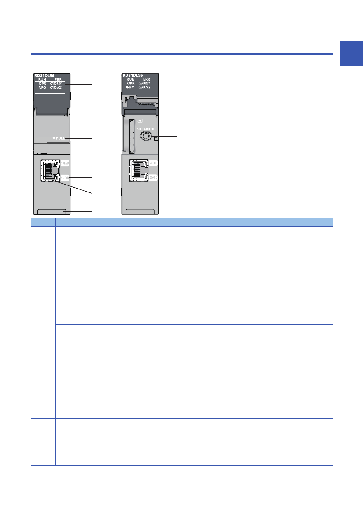
1 PART NAMES
(2)
(3)
(4)
(8)
(5)
(1)
(6)
(7)
This chapter shows the part names of a high speed data logger module.
1
No. Name Description
(1) RUN LED Indicates the operating status.
ERR LED Indicates the error status.
OPR LED Indicates the module status.
INFO LED Indicates every information.
CARD RDY LED Indicates the availability of the SD memory card.
CARD ACS LED Indicates the access status of the SD memory card.
(2) Slot cover A cover of the SD memory card slot and the SD memory card lock switch.
(3) SPEED LED Indicates the communication speed and the link status for Ethernet.
(4) SD/RD LED Indicates the data sending/receiving status for Ethernet.
• ON: In operation
• Flashing: Checking module, selecting the module for online module change
(Flashes for 10 seconds in "Checking module" when the [Checking module] button is pressed on the
"Find High Speed Data Logger Module" screen of the configuration tool.)
• OFF: Watchdog timer error (hardware failure), module replacement allowed in the process of the online
module change
• ON: Minor error occurring/WDT error occurring (hardware error)
• Flashing: Moderate error or major error
• OFF: In normal status
• ON: Module operating status is in operation
• Flashing: Module operating status is initializing (update settings, etc.) and stopping
• OFF: Module operating status is stopped
• ON: Warning
• OFF: In normal status
• ON: SD memory card accessible status (mounted status)
• Flashing: SD memory card mounting/unmounting
• OFF: SD memory card inaccessible status (not installed/Unmounted)
• ON: Accessing SD memory card
• OFF: SD memory card not accessed
Open this cover to insert/remove an SD memory card or to operate the switch.
Close the cover unless inserting/removing an SD memory card or operating the switch to prevent foreign
material intrusion such as dust.
• ON (orange): Linking-up (1000 Mbps)
• Flashing (green): Linking-up (100 Mbps)
• OFF: Linking-down or linking-up (10 Mbps)
• ON: Sending/receiving data
• OFF: No data sending/reception
1 PART NAMES
21
Page 24

No. Name Description
(5) Ethernet port A port for connecting a high speed data logger module to 10BASE-T/100BASE-TX/1000BASE-T
(High speed data logger modules distinguish among 10BASE-T, 100BASE-TX, and 1000BASE-T
according to an external device.)
(6) SD memory card lock switch
(SD CARD OFF button)
(7) SD memory card slot A slot to insert an SD memory card.
(8) Product information marking Displays the product information (16 digits) of the module.
A switch for disabling access to an SD memory card to remove it.
Removing an SD memory card is prohibited while the CARD RDY LED is ON or flashing.
For inserting and removing an SD memory card, refer to the following section.
Page 62 SD Memory Card
• When checking the module at online module change, the RUN LED of the high speed data logger module
and the READY LED of the CPU module flash for more than 10 seconds at the same time.
Make sure to check not only the RUN LED also the READY LED of the CPU module.
• The cause of the INFO LED lightning can be checked with the INFO LED information on the "Module
Diagnostics" screen or buffer memory. Check the cause of LED lightning and take corrective actions.
(MELSEC iQ-R High Speed Data Logger Module User's Manual(Application))
22
1 PART NAMES
Page 25

2 SPECIFICATIONS
This chapter explains the performance specifications and accessible devices/device range of a high speed data logger
module.
2.1 Performance Specifications
The following table shows the performance specifications of a high speed data logger module.
Transmission and interface specifications
Item Specification
Ethernet Interface 1000BASE-T 100BASE-TX 10BASE-T
Data transmission rate 1 Gbps 100 Mbps 10 Mbps
Transmission method Base band
Number of cascade connections
(When using a repeater hub)
Maximum segment length 100 m (length between a hub and a node)
Supported function Auto-negotiation (automatic recognition of the communication speed/communication
IP version IPv4 supported
SD memory card slot Supply power voltage 3.3 VDC
Supply power capacity Up to 200 mA
Interface SD memory card/SDHC memory card
Number of insertable cards 1 card
Number of occupied I/O points 32 points (I/O assignment: Intelligent 32 points)
Clock Acquired from a CPU module (CPU No.1 in a multiple CPU system).
5 VDC internal current consumption 1.1 A
External dimensions Height 106 mm
Width 27.8 mm
Depth 110 mm
Weight 0.24 kg
Maximum 2 levels Maximum 4 levels
method)
Auto-MDI/MDI-X (automatic recognition of a straight/crossing cable)
Time accuracy after obtaining the time, daily error of ±9.504 seconds
2
2 SPECIFICATIONS
2.1 Performance Specifications
23
Page 26

Functional specifications
Data sampling performance specifications
The following table lists the specifications for the data sampling used for the data logging function, the event logging function,
and the report function.
Item Specifications
Data sampling Number of access target CPUs Maximum 64 CPUs
Sampling interval High speed sampling • Sequence scan time synchronization
• 0.5 to 0.9 milliseconds, 1 to 32767 milliseconds (for trigger logging)
• 2 to 32767 milliseconds (for continuous logging)
Number of units of
sampled data
Data type
Data output format
(Unicode text file, CSV file)
Scaling
*1,*2,*3
*6
*8
*9
General sampling • 0.1 to 0.9 seconds, 1 to 32767 seconds
High speed sampling Total number of units of data: 32768 (per setting: 1024)
General sampling Total number of units of data: 65536 (per setting: 1024)
• Time interval specification (specify hour/minute/second)
*4,*5
Total number of device points: 32768
Total number of device points: 262144 (per setting: 4096)
•Bit
• Word [Signed]
• Double Word [Signed]
• Word [Unsigned]/Bit String [16-bit]
• Double Word [Unsigned]/Bit String [32-bit]
• FLOAT [Single Precision]
• FLOAT [Double Precision]
• 16bit BCD
• 32bit BCD
• String: 1 to 8192 characters
• Raw: 1 to 8192 bytes
•Bit
• Decimal format: 0 to 14 digits after the decimal point
• Exponential format: 0 to 14 digits after the decimal point
• Hexadecimal format
•String
•Raw
■For trigger logging (output only one line after triggering), following conditions
can be specified.
• Time/Total time
Decimal format: 0 to 4 digits after the decimal point
• Count/Total count
Decimal format: 0 digit after the decimal point
Basic arithmetic operations: calculations combining (×, ÷) and (+, -)
*7
(per setting: 4096)
24
2 SPECIFICATIONS
2.1 Performance Specifications
Page 27
*1 The number of device points available for a piece of data differs depending on the data type.
*2 The total number of sampling data of data logging, event logging, and report data.
*3 The total number of units of sampled data per setting is as follows only when the creation trigger and current value data are not
synchronized in the report setting.
Total number of units of data (per setting): 65535, device points (per setting): 65535
However, note that the number of device points per setting of data excluding the current value data is up to 4096.
*4 In high-speed sampling, target data is sampled by synchronizing with a sequence scan from a control CPU module by using the
sequence scan synchronization sampling function of a control CPU module.
When multiple intelligent function modules use the sequence scan synchronization sampling function, note the total number of points for
target data. If it exceeds the number of points that can be sampled, an error may occur in registration processing of an intelligent
function module registered later.
*5 If the number of device points for high speed sampling is increased, an error may occur when updating the settings. If an error occurred,
take the following corrective action.
⋅ Check the settings of other intelligent function modules controlled by the control CPU module, and adjust it so that the total number of
device points for the sequence scan synchronization sampling function does not exceed the number of points that can be sampled.
⋅ Power OFF to ON, or reset the control CPU.
⋅ Return the number of device points to the original settings.
*6 The data type when reading data from the device memory in the CPU module.
*7 The number of characters is determined by the specified size.
For Unicode text file and binary file format, the maximum number of characters is 4096 characters because one character contains two
bytes.
*8 The format when data is output to Unicode text file or CSV file with data logging or event logging.
Binary files are output in the binary format.
Reports are output in Excel cell format.
*9 A function to perform data scaling and offset calculations.
■Target sampling data
Type Data type
Data logging Logging target data, trigger condition data, period condition data, file switching condition data, saved file name data,
saved folder name data, e-mail transmission data
Event logging Monitoring data, period condition data, file switching condition data, saved file name data, saved folder name data, e-
mail transmission data
Report Current value data, creation trigger condition data, period condition data, saved file name data, saved folder name
data, e-mail transmission data
2
The data logging, event logging, and report functions are best effort functions.
Since module processing time changes according to the settings and status of other devices, it may not
operate with the set data sampling interval.
Run the system by fully verifying the processing time of each function when constructing it.
For processing time, refer to the following manual.
MELSEC iQ-R High Speed Data Logger Module User's Manual(Application)
2 SPECIFICATIONS
2.1 Performance Specifications
25
Page 28

Data logging performance specifications
Item Specifications
Data logging Number of settings Up to 64
Logging type • Continuous logging
File format
Period Specify the applicable period or exclusion period.
Trigger logging Trigger condition
File switching timing Number of lines (number
*2
(Single condition)
Trigger condition
(Compound condition OR combine)
Trigger condition
(Compound condition AND combine)
Trigger condition
(Compound condition Number of times)
Trigger condition
(Compound condition Order)
Number of logging lines
of records) specification
File size specification 10 to 16384 KB
Condition specification • Data conditions (comparison): Bit ON/OFF, compare data to constant value,
Trigger logging unit At the time of trigger logging file output completion
*4
*1
• Trigger logging (output only one line after triggering)
• Trigger logging (output the lines before and after triggering)
• Unicode text file (extension: .TXT)
• CSV file (extension: .CSV)
• Binary file (extension: .BIN)
• Data condition: Bit ON/OFF, compare data to constant value, compare data to
data
• Date range: Specify the start and end in month and day
• Time range: Specify the start and end in hour, minute, and second
• Day of the week/Week of the month conditions: Specify the day of the week
and week
• Data conditions (comparison): Bit ON/OFF, compare data to constant value,
compare data to data
• Data conditions (value change)
• Fixed cycle: 1 to 86400 seconds
• Time interval specification: Specify hour/minute/second
• Time specification: Specify month, day, hour, minute, second
• At module startup
• Data conditions (comparison): Bit ON/OFF, compare data to constant value,
compare data to data
Specify the start condition, terminal condition, and count condition. (Up to 3
conditions)
• Data conditions (comparison): Bit ON/OFF, compare data to constant value,
compare data to data
• Data conditions (value change)
Specify the start condition and order (1st condition, 2nd condition, or 3rd
condition). (Up to 4 conditions)
• Data conditions (comparison): Bit ON/OFF, compare data to constant value,
compare data to data
• Data conditions (value change)
• Before trigger occurs: 0 to 65534 lines
• After trigger occurs: 1 to 65535 lines
The sum of lines of before and after trigger occurrence is up to 65535 lines.
100 to 100000 lines
compare data to data
• Data conditions (value change)
• Fixed cycle: 1 to 86400 seconds
• Time interval specification: Specify hour/minute/second
• Time specification: Specify month, day, hour, minute, second
• At module startup
*3
26
2 SPECIFICATIONS
2.1 Performance Specifications
Page 29

Item Specifications
Data logging Number of saved files
Saved file name ■Simple setting
Folder switching timing Condition specification • Data conditions (comparison): Bit ON/OFF, compare data to constant value,
Saved folder name ■Simple setting
*5
1 to 65535
• Add the name
• Add the date (4-digit year, month, day)
• Add the time (hour, minute, second)
• Add the sequential number
■Detailed setting
• 4-digit year/2-digit year, month, day, day of the week, hour, minute, second
• Device value (two types)
• Sequential number
compare data to data
• Data conditions (value change)
• Fixed cycle: 1 to 86400 seconds
• Time interval specification: Specify hour/minute/second
• Time specification: Specify month, day, hour, minute, second
• At module startup
• Add the name
• Add the date (4-digit year, month, day)
• Add the time (hour, minute, second)
• Add the sequential number
■Detailed setting
• 4-digit year/2-digit year, month, day, day of the week, hour, minute, second
• Device value (two types)
• Sequential number
*1 Up to 64 settings can be configured by combining data logging, event logging, and report function.
Of these, up to 32 settings can be configured for data logging, event logging, and report function when high speed sampling is specified.
*2 For the output file format, refer to the following manual.
MELSEC iQ-R High Speed Data Logger Module User's Manual(Application)
*3 By using the report function, data can be output again in Excel file format.
*4 The number of logging lines setting is affected by the amount of memory (trigger buffer) where sampled data is temporarily saved.
Since the amount of trigger buffer has an upper limit, there may be situations where the listed number of logging lines cannot be set.
Confirm the trigger buffer usage amount as given below. Do not exceed the upper limit.
MELSEC iQ-R High Speed Data Logger Module User's Manual(Application)
*5 When a subfolder is not created in the save folder, the number of saved files is in the range of 1 to 256.
2
■Restrictions on data logging
The restrictions on performance specifications of data logging are as follows.
Item High speed sampling General sampling
Total trigger buffer size Up to 20 MB in total using 32 settings*1Up to 20 MB in total using 64 settings
Total number of period condition, trigger condition, file switching
condition, and folder switching condition
Period condition Up to 4 conditions Up to 8 conditions
Trigger condition Up to 4 conditions Up to 8 conditions
File switching condition Up to 4 conditions Up to 8 conditions
Folder switching condition Up to 4 conditions Up to 8 conditions
*1 Size of the combined high speed sampling and general sampling.
When 20 MB is used for high speed sampling, trigger logging of general sampling cannot be added.
Up to combination of 5 conditions Up to combination of 10 conditions
*1
2 SPECIFICATIONS
2.1 Performance Specifications
27
Page 30

Event logging performance specifications
Item Specifications
Event logging Number of settings Up to 64
Number of events Up to 256 per event logging setting
File format
Event condition Event condition
Period Specify the applicable period or exclusion period.
File switching timing Number of lines (number
Number of saved files
Saved file name ■Simple setting
Folder switching timing Condition specification • Data conditions (comparison): Bit ON/OFF, compare data to constant value,
*2
(Single condition)
Event condition
(Compound condition Comparison - AND
combine)
Event condition
(Compound condition Comparison - OR
combine)
Event condition
(Compound condition Number of times)
Event condition
(Compound condition Order)
of records) specification
File size specification 10 to 16384 KB
Condition specification • Data conditions (comparison): Bit ON/OFF, compare data to constant value,
*3
*1
• Unicode text file (extension: .TXT)
• CSV file (extension: .CSV)
• Binary file (extension: .BIN)
• Data conditions (comparison): Bit ON/OFF, compare data to constant value,
compare data to data
• Data conditions (value change)
• Data conditions (comparison): Bit ON/OFF, compare data to constant value,
compare data to data
• Data conditions (comparison): Bit ON/OFF, compare data to constant value,
compare data to data
Specify the start condition, terminal condition, and count condition. (Up to 3
conditions)
• Data conditions (comparison): Bit ON/OFF, compare data to constant value,
compare data to data
• Data conditions (value change)
Specify the start condition and order (1st condition, 2nd condition, or 3rd
condition). (Up to 4 conditions)
• Data conditions (comparison): Bit ON/OFF, compare data to constant value,
compare data to data
• Data conditions (value change)
• Data condition: Bit ON/OFF, compare data to constant value, compare data to
data
• Date range: Specify the start and end in month and day
• Time range: Specify the start and end in hour, minute, and second
• Day of the week/Week of the month conditions: Specify the day of the week
and week
100 to 100000 lines
compare data to data
• Data conditions (value change)
• Fixed cycle: 1 to 86400 seconds
• Time interval specification: Specify hour/minute/second
• Time specification: Specify month, day, hour, minute, second
• At module startup
1 to 65535
• Add the name
• Add the date (4-digit year, month, day)
• Add the time (hour, minute, second)
• Add the sequential number
■Detailed setting
• 4-digit year/2-digit year, month, day, day of the week, hour, minute, second
• Device value (two types)
• Sequential number
compare data to data
• Data conditions (value change)
• Fixed cycle: 1 to 86400 seconds
• Time interval specification: Specify hour/minute/second
• Time specification: Specify month, day, hour, minute, second
• At module startup
28
2 SPECIFICATIONS
2.1 Performance Specifications
Page 31

Item Specifications
Event logging Saved folder name ■Simple setting
• Add the name
• Add the date (4-digit year, month, day)
• Add the time (hour, minute, second)
• Add the sequential number
■Detailed setting
• 4-digit year/2-digit year, month, day, day of the week, hour, minute, second
• Device value (two types)
• Sequential number
*1 Up to 64 settings can be configured by combining data logging, event logging, and report function.
Of these, up to 32 settings can be configured for data logging, event logging, and report function when high speed sampling is specified.
*2 For the output file format, refer to the following manual.
MELSEC iQ-R High Speed Data Logger Module User's Manual(Application)
*3 When a subfolder is not created in the save folder, the number of saved files is in the range of 1 to 256.
■Restrictions on event logging
The restrictions on performance specifications of event logging are as follows.
Item High speed sampling General sampling
Total number of event condition, period condition, file switching
condition, and folder switching condition
Event condition Up to 4 conditions
Period condition Up to 4 conditions Up to 8 conditions
File switching condition Up to 4 conditions Up to 8 conditions
Folder switching condition Up to 4 conditions Up to 8 conditions
Up to combination of 5 conditions Up to combination of 10 conditions
2
2 SPECIFICATIONS
2.1 Performance Specifications
29
Page 32

Report function performance specifications
Item Specifications
Report Number of settings Up to 64
File format Excel file (extension: .xls)
Output data type • Data inside data logging file
Number of units of output data 64 layouts per report setting, 65535 cells in total
Creation trigger Trigger condition
(Single condition)
Trigger condition
(Compound condition OR combine)
Trigger condition
(Compound condition AND combine)
Trigger condition
(Compound condition Number of times)
Trigger condition
(Compound condition Order)
Period Specify the applicable period or exclusion period.
Layout file size Maximum 10 MB
Number of saved files 1 to 65535
Saved file name ■Simple setting
Folder switching timing Condition specification • Data conditions (comparison): Bit ON/OFF, compare data to constant value,
*1
• Current value data
• Creation time
• Data conditions (comparison): Bit ON/OFF, compare data to constant value,
compare data to data
• Data conditions (value change)
• Fixed cycle: 1 to 86400 seconds
• Time interval specification: Specify hour/minute/second
• Time specification: Specify month, day, hour, minute, second
• At module startup
• At the data logging file switching
• Data conditions (comparison): Bit ON/OFF, compare data to constant value,
compare data to data
Specify the start condition, terminal condition, and count condition. (Up to 3
conditions)
• Data conditions (comparison): Bit ON/OFF, compare data to constant value,
compare data to data
• Data conditions (value change)
Specify the start condition and order (1st condition, 2nd condition, or 3rd
condition). (Up to 4 conditions)
• Data conditions (comparison): Bit ON/OFF, compare data to constant value,
compare data to data
• Data conditions (value change)
• Data condition: Bit ON/OFF, compare data to constant value, compare data to
data
• Date range: Specify the start and end in month and day
• Time range: Specify the start and end in hour, minute, and second
• Day of the week/Week of the month conditions: Specify the day of the week
and week
• Add the name
• Add the date (4-digit year, month, day)
• Add the time (hour, minute, second)
• Add the sequential number
■Detailed setting
• 4-digit year/2-digit year, month, day, day of the week, hour, minute, second
• Device value (two types)
• Sequential number
compare data to data
• Data conditions (value change)
• Fixed cycle: 1 to 86400 seconds
• Time interval specification: Specify hour/minute/second
• Time specification: Specify month, day, hour, minute, second
• At module startup
*2
30
2 SPECIFICATIONS
2.1 Performance Specifications
Page 33

Item Specifications
Report Saved folder name ■Simple setting
• Add the name
• Add the date (4-digit year, month, day)
• Add the time (hour, minute, second)
• Add the sequential number
■Detailed setting
• 4-digit year/2-digit year, month, day, day of the week, hour, minute, second
• Device value (two types)
• Sequential number
*1 Up to 64 settings can be configured by combining data logging, event logging, and report function.
Of these, up to 32 settings can be configured for data logging, event logging, and report function when high speed sampling is specified.
*2 Only binary format data logging can be output in a report.
■Restrictions on report function
The restrictions on performance specifications of report are as follows.
Item High speed sampling General sampling
Total of layout file sizes Up to 10 MB in total using 32 settings Up to 10 MB in total using 64 settings
Total number of period condition, creation trigger condition, and folder
switching condition
Period condition Up to 4 conditions Up to 8 conditions
Creation trigger condition Up to 4 conditions Up to 8 conditions
Folder switching condition Up to 4 conditions Up to 8 conditions
Up to combination of 5 conditions Up to combination of 10 conditions
Other functions performance specifications
2
Item Specifications
E-mail Application • Notification when event occurs
• Transmit saved file
Subject • Event notification e-mail: User specified
• Saved file transmission e-mail: Automatically created/user specified
FTP server
FTP transfer
(client)
Shared folder
transfer
*1
Body • Event notification e-mail: User specified
Attachment • Event notification e-mail: None
Attachment format MIME format
MIME version 1.0
Communications with mail
server
Target address Up to 16 groups
Operability verified e-mail client software Microsoft Outlook 2013
Application • Read and delete saved files
Operability verified FTP client software Windows Internet Explorer 8.0
Session count
*3
Application Transfer saved files
Operability verified FTP server software Microsoft Internet Information Services
Number of transfer destination settings Up to 16 settings
Application Transfer saved files
Operability verified operating system Windows 10 (Home, Pro, Enterprise, Education)
Number of transfer destination settings Up to 16 settings
*2
Port number 25, 587, other (1 to 65535)
Authentication method • No authentication
• Saved file transmission e-mail: Automatically created/user specified
• Saved file transmission e-mail: Saved file (Unicode text file, binary file, CSV
file, or Excel file), up to 512 KB
• SMTP-AUTH (PLAIN, LOGIN, CRAM-MD5)
• POP before SMTP
• Write, read, and delete recipe files
Windows Internet Explorer 9.0
Windows Internet Explorer 10.0
Windows Internet Explorer 11.0
10
*4
Windows 8.1, Windows 8.1 (Pro, Enterprise)
Windows 8, Windows 8 (Pro, Enterprise)
Windows 7 (Starter, Home Premium, Professional , Ultimate, Enterprise)
*4
2 SPECIFICATIONS
2.1 Performance Specifications
31
Page 34

Item Specifications
Recipe Number of units of data Up to 256 data
Number of records Up to 256 records
Data type • Bit
• Word [Signed]
• Double Word [Signed]
• Word [Unsigned]/Bit String [16-bit]
• Double Word [Unsigned]/Bit String [32-bit]
• FLOAT [Single Precision]
• FLOAT [Double Precision]
• 16bit BCD
• 32bit BCD
Recipe file
Execution type Dedicated instructions (ladder program), configuration tool
*5
CSV file (extension: .CSV), maximum 256 files
*1 A function to access the high speed data logger module (FTP server) from a personal computer's FTP client software.
For the corresponding FTP command, refer to the following manual.
MELSEC iQ-R High Speed Data Logger Module User's Manual(Application)
*2 The upper limit of the number of simultaneous connections to the high speed data logger module from FTP client software.
FTP client software may use multiple connections per single access session.
*3 A function to access the personal computer's FTP server software from the high speed data logger module (FTP client).
*4 The sum of transfer destination settings in the FTP client and shared folder is up to 16 settings.
*5 For the output file format, refer to the following manual.
MELSEC iQ-R High Speed Data Logger Module User's Manual(Application)
32
2 SPECIFICATIONS
2.1 Performance Specifications
Page 35

2.2 Accessible Routes and Devices
This section shows the accessible routes and devices.
Accessible CPU modules
Series Model Data sampling
method
*1
RCPU
QCPU (Q mode) Programmable controller
LCPU Programmable controller
*1 When using high speed sampling, use a CPU module supporting the sequence scan synchronization sampling function.
For a CPU module supporting the sequence scan synchronization sampling function, refer to the manual for the CPU module.
*2 Use a high speed data logger module with the firmware version '05' or later.
*3 It cannot be used as a relay station.
*4 Only a module with a serial number of which the first five digits are 12042 or higher can be accessed.
Programmable controller
CPU
Process CPU R08PCPU, R16PCPU, R32PCPU, and R120PCPU • General sampling
C Controller module
CPU
Process CPU Q02PHCPU, Q06PHCPU, Q12PHCPU, and Q25PHCPU
C Controller module
CPU
R00CPU*2, R01CPU*2, R02CPU*2, R04CPU, R04ENCPU, R08CPU,
R08ENCPU, R16CPU, R16ENCPU, R32CPU, R32ENCPU, R120CPU,
and R120ENCPU
*3
R12CCPU-V
Q00JCPU, Q00UJCPU, Q00CPU, Q00UCPU, Q01CPU, Q01UCPU,
Q02CPU, Q02HCPU, Q02UCPU, Q03UDCPU, Q03UDECPU,
Q03UDVCPU, Q04UDHCPU, Q04UDEHCPU, Q04UDVCPU,
Q06HCPU, Q06UDHCPU, Q06UDEHCPU, Q06UDVCPU,
Q10UDHCPU, Q10UDEHCPU, Q12HCPU, Q13UDHCPU,
Q13UDEHCPU, Q13UDVCPU, Q20UDHCPU, Q20UDEHCPU,
Q25HCPU, Q26UDHCPU, Q26UDEHCPU, Q26UDVCPU,
Q50UDEHCPU, and Q100UDEHCPU
*3
Q12DCCPU-V*4, Q24DHCCPU-V, Q24DHCCPU-LS, and
Q24DHCCPU-VG
L02CPU, L02CPU-P, L02SCPU, L06CPU, L26CPU, L26CPU-BT, and
L26CPU-PBT
• High speed sampling
• General sampling
2
2 SPECIFICATIONS
2.2 Accessible Routes and Devices
33
Page 36

Accessible routes
ÒÓ Ô Õ
Ö×
(1)
(2)
(3)
1
2・・ ・ 8
1
2・・ ・ 8
The following figure shows accessible routes from a high speed data logger module.
: Access routes from a high
speed data logger module
: Connection with an Ethernet
port of the high speed data logger
module
: Connection by specifying a
network number and a station number
of the target station in each module.
: Connection by
specifying a start I/O number
and a station number of the
target station in each module.
Accessible routes Reference
(1) Own station (Control CPU, other
CPUs in multiple CPUs)
(2) Another station via single network Access from the Ethernet port of a high speed data logger module Page 35 Access from the Ethernet
(3) Another station via co-existence
network
Own station (Control CPU, other CPUs in multiple CPUs) Page 35 Own station (Control CPU,
other CPUs in multiple CPUs)
port of a high speed data logger
module
Access by specifying the network number and station number of the
target station.
Access by specifying the start I/O number of the module for accessing
the target station and station number of the other station
Access by specifying the network number and station number of the
target station from the station, on which the start I/O number and the
station number of the module for accessing the target station are specified
and accessed.
Access by specifying the start I/O number of the module for accessing
the target station and station number of the target station from the station,
on which the network number and the station number of the target station
are specified and accessed.
Page 36 Access by specifying the
network number and station number
of the target station
Page 36 Access by specifying the
start I/O number of the module for
accessing the target station and
station number of the target station
Page 37 Access by specifying the
network number and station number,
via another station on CC-Link or C24
Page 37 Access to another station on
CC-Link or C24 from another station
on which the network number and the
station number are specified
If network load is high, data will not be processed on the device on the access route (including access target
CPU) and a timeout error may occur and data sampling may fail. If a timeout error occurs, adjust the network
load.
34
2 SPECIFICATIONS
2.2 Accessible Routes and Devices
Page 37

Own station (Control CPU, other CPUs in multiple CPUs)
The following table shows the accessible route to a CPU module of the high speed data logger module-mounted station.
: Accessible, : No combination
Access route Access destination CPU module (series)
RCPU QCPU (Q mode) LCPU
Programm
able
controller
CPU/
Process
CPU
Control CPU
Other CPUs in multiple CPUs
*1 RnENCPU is not applicable.
*1
(PLC No.1 to
No.4)
C
Controller
module
Programm
able
controller
CPU/
Process
CPU
C
Controller
module
Programm
able
controller
CPU
Another station via single network
■Access from the Ethernet port of a high speed data logger module
The following table shows the accessible route when accessing from an Ethernet port of a high speed data logger module in
the status where an access target CPU is connected to a network.
The communication target from an Ethernet port of the high speed data logger module, Ethernet module or CPU module
(Ethernet port) can be specified.
: Accessible, : No combination
Access route Access destination CPU module (series)
RCPU QCPU (Q mode) LCPU
Ethernet
• High speed data logger module Ethernet port → CPU module (Ethernet
port)
• High speed data logger module Ethernet port → Ethernet module
Programm
able
controller
CPU/
Process
CPU
(PLC No.1 to
No.4)
C
Controller
module
(PLC No.1 to
No.4)
Programm
able
controller
CPU/
Process
CPU
*1,*2
(PLC No.1 to
No.4)
C
Controller
module
*3
(Host CPU)
Programm
able
controller
CPU
2
*1 An Ethernet module-mounted station or built-in Ethernet CPU can be accessed. Access via relay station is not possible.
*2 UDP (MELSOFT Connection) needs to be added to the open setting for a built-in Ethernet port of an access target CPU.
*3 When accessing an Ethernet port of Q12DCCPU-V (Basic mode) directly, MELSOFT connection needs to be permitted in the
Q12DCCPU-V (Basic mode) setting.
For details on the setting, refer to the following manual.
C Controller Module User's Manual (Utility Operation, Programming)
2 SPECIFICATIONS
2.2 Accessible Routes and Devices
35
Page 38

■Access by specifying the network number and station number of the target station
The following table shows the accessible route when an access target CPU module can be specified by a network number
and a station number (or CPU number) from the high speed data logger module-mounted station, in the status where the
target device is connected to a network.
The access to the CPU module that is mounted on the eighth network is available via a relay station of RCPU or QCPU (Q
mode).
: Accessible, : No combination
Access route Access destination CPU module (series)
RCPU QCPU (Q mode) LCPU
Programm
able
controller
CPU/
Process
CPU
CC-Link IE Controller Network
CC-Link IE Field Network
MELSECNET/H
Ethernet
*1
Via own Ethernet module
(PLC No.1 to
No.4)
*1 Only Ethernet modules can be accessed from the own station.
C
Controller
module
(PLC No.1 to
No.4)
Programm
able
controller
CPU/
Process
CPU
(PLC No.1 to
No.4)
C
Controller
module
(Host CPU)
Programm
able
controller
CPU
■Access by specifying the start I/O number of the module for accessing the target station and
station number of the target station
The following table shows the accessible route when connecting an access target CPU module and the side on which high
speed data logger module is mounted directly.
: Accessible, : Not accessible
Access route Access destination CPU module (series)
RCPU QCPU (Q mode) LCPU
Programm
able
controller
CPU/
Process
CPU
CC-Link
(PLC No.1 to
No.4)
C24
C
Controller
module
(PLC No.1 to
No.4)
Programm
able
controller
CPU/
Process
CPU
(PLC No.1 to
No.4)
C
Controller
module
(Host CPU)
Programm
able
controller
CPU
36
2 SPECIFICATIONS
2.2 Accessible Routes and Devices
Page 39

Another station via co-existence network
■Access by specifying the network number and station number, via another station on CC-Link
or C24
The following table shows the accessible route when accessing by specifying a network number and a station number via
other stations (the first route) on CC-Link or C24 from the side on which a high speed data logger module is mounted.
: Accessible, : No combination
First access route Second access route
(Co-existence network)
CC-Link
C24
CC-Link IE Controller Network
CC-Link IE Field Network
MELSECNET/H
Ethernet (via Ethernet module)
■Access to another station on CC-Link or C24 from another station on which the network
number and the station number are specified
The following table shows the accessible route when accessing other stations on CC-Link or C24 via a station (the first route)
specified by a network number and a station number from the side on which a high speed data logger module is mounted.
: Accessible, : Not accessible
First access route Second access route
(Co-existence network)
CC-Link IE Controller Network CC-Link
MELSECNET/H
CC-Link IE Field Network
Ethernet (via Ethernet module)
CC-Link IE Controller Network C24
MELSECNET/H
CC-Link IE Field Network
Ethernet (via Ethernet module)
Access destination CPU module (series)
RCPU QCPU (Q mode) LCPU
Programm
able
controller
CPU/
Process
CPU
(PLC No.1 to
No.4)
Access destination CPU module (series)
RCPU QCPU (Q mode) LCPU
Programm
able
controller
CPU/
Process
CPU
(PLC No.1 to
No.4)
C
Controller
module
(PLC No.1 to
No.4)
C
Controller
module
(PLC No.1 to
No.4)
Programm
able
controller
CPU/
Process
CPU
(PLC No.1 to
No.4)
Programm
able
controller
CPU/
Process
CPU
(PLC No.1 to
No.4)
C
Controller
module
(Host CPU)
C
Controller
module
(Host CPU)
Programm
able
controller
CPU
Programm
able
controller
CPU
2
2 SPECIFICATIONS
2.2 Accessible Routes and Devices
37
Page 40

Accessible devices
The following tables lists the accessible devices.
High speed sampling is possible only for the RCPU that controls the high speed data logger module.
: Accessible, : Not accessible
Device *1 (Device name) Access destination CPU module (series)
RCPU QCPU (Q mode) LCPU
Programmable controller
CPU/Process CPU
General
sampling
Function input (FX)
Function output (FY)
Function register (FD)
Special relay (SM)
Special register (SD)
Input relay (X)
Output relay (Y)
Internal relay (M)
Latch relay (L)
Annunciator (F)
Edge relay (V)
Link relay (B)
Data register (D)
Link register (W)
Extended data register (D)
Extended link register (W)
Timer Contact (TS)
Long timer Contact (LTS)
Counter Contact (CS)
Long counter Contact (LCS)
Retentive timer Contact (STS, SS
Long retentive
timer
Link special relay (SB)
Link special register (SW)
Step relay (S)
Direct input (DX)
Direct output (DY)
Index register (Z)
*5
*5
Coil (TC)
Current value (T/TN)
Coil (LTC)
Current value (LT/LTN)
Coil (CC)
Current value (C/CN)
Coil (LCC)
Current value (LC/LCN)
*7
*7
Coil (STC, SC
Current value (ST/STN,
ST/SN
Contact (LSTS)
Coil (LSTC)
Current value (LST/
LSTN)
)
*7)*6
*6
*3
*3
*6
*6
*6
*6
)
*2
High speed
sampling
C Controller
module
Programma
ble
controller
CPU/
Process
CPU
C Controller
module
*3
*3
*3
*3
*3
*4
*3
*4
Programma
ble
controller
CPU
38
2 SPECIFICATIONS
2.2 Accessible Routes and Devices
Page 41

Device *1 (Device name) Access destination CPU module (series)
RCPU QCPU (Q mode) LCPU
Programmable controller
CPU/Process CPU
General
sampling
*2
High speed
sampling
C Controller
module
Programma
ble
controller
CPU/
Process
C Controller
module
Programma
ble
controller
CPU
CPU
Long index register (LZ)
File register (R)
(ZR)
(ERn\R)
Link direct device Link input (Jn\X)
Link output (Jn\Y)
Link relay (Jn\B)
Link special relay (Jn\SB)
Link register (Jn\W)
Link special register
(Jn\SW)
Refresh data register (RD)
Module access
device
CPU buffer
memory access
device
Module access device/
Intelligent function module
device (Un\G)
Multiple CPU shared
device (U3En\G)
CPU buffer memory
access device (U3En\G)
CPU buffer memory
access device (fixed cycle
communication area)
(U3En\HG)
*8
*8
*9
*9
*1 The local devices and file registers for individual programs cannot be accessed by specifying the program name.
Do not use local devices and file registers for individual programs since they may not be read/written correctly.
*2 Process CPU does not support high speed sampling.
*3 For Q12DCCPU-V (Basic mode), select "Use device function" on a C Controller module.
*4 For Q12DCCPU-V, only Q12DCCPU-V (Extended mode) can be accessed.
*5 The extended data register (D) and extended link register (W) can be accessed by the following two methods.
⋅ Directly specify in the device name of extended data register (D) and extended link register (W)
⋅ Access to the file register (ZR) area assigned to the extended data register (D) and extended link register (W)
*6 Either of the device names can be specified.
*7 Device names for QCPU (Q mode), LCPU, and MELSEC-Q series C Controller module.
*8 When accessing out of the range of the file register (ZR) area, the value of -1(FFFFH) is sampled.
*9 It is not accessible when using Q00JCPU and Q00UJCPU.
2
2 SPECIFICATIONS
2.2 Accessible Routes and Devices
39
Page 42

Bit specification/digit specification of devices
The following table shows the availability of the digit-specified and bit-specified devices.
When using the high speed sampling function and recipe function, bit specified/digit specified devices cannot be used.
Bit specified/digit specified devices cannot be used for the current value data in the reports.
: Possible, : Not possible
Device (device name) Bit specification Digit specification
Special relay (SM)
Special register (SD)
Input relay (X)
Output relay (Y)
Internal relay (M)
Latch relay (L)
Annunciator (F)
Edge relay (V)
Link relay (B)
Data register (D)
Link register (W)
Timer Contact (TS)
Coil (TC)
Current value (T/TN)
Long timer Contact (LTS)
Coil (LTC)
Current value (LT/LTN)
Counter Contact (CS)
Coil (CC)
Current value (C/CN)
Long counter Contact (LCS)
Coil (LCC)
Current value (LC/LCN)
*2
Retentive timer Contact (STS, SS
Coil (STC, SC
Current value (ST/STN, ST/SN
Long retentive timer Contact (LSTS)
Coil (LSTC)
Current value (LST/LSTN)
Link special relay (SB)
Link special register (SW)
Index register (Z)
File register (R)
(ZR)
Link direct device Link input (Jn\X)
Link output (Jn\Y)
Link relay (Jn\B)
Link special relay (Jn\SB)
Link register (Jn\W)
Link special register (Jn\SW)
Module access device Module access device/Intelligent function
module device (Un\G)
Multiple CPU shared device (U3En\G)
)
*2
)
*2
)
*1
*1 Specified by QCPU (Q mode) or LCPU only.
*2 Device names for QCPU (Q mode), LCPU, and MELSEC-Q series C Controller module.
2 SPECIFICATIONS
40
2.2 Accessible Routes and Devices
Page 43

Device specification with labels/comments
A device can be specified with a label or a comment by importing global labels (including module labels) set with an
engineering tool to a project of the configuration tool.
For details on importing labels, refer to the following manual.
MELSEC iQ-R High Speed Data Logger Module User's Manual(Application)
Access units
The following table shows the number of device points (access units) that can be accessed in a single process when sampling
the device values in the CPU module.
When the number of sampling device points are lower than the access units, the device values of the same sequence scan
are sampled.
Since device values are sampled over multiple sequence scans when the number of sampling device points exceed the
access units, data inconsistency (old data and new data overlap) may occur.
To prevent data inconsistency, set the number of devices sampled at one time to less than the access units, or use high speed
sampling.
Series High speed
sampling
RCPU Programmable
controller CPU
Process CPU Not supported.
C Controller module
QCPU (Q mode) Excluding basic model
QCPU
Basic model QCPU
C Controller module
LCPU Programmable
controller CPU
Samples all device
values in the same
sequence scan.
*8
*7
*8
General
sampling
118 points
58 points
96 points
48 points
64 points 240 points
96 points
48 points
96 points
48 points
*1
*2
*1
*2
*1
*2
*1
*2
Report current
value data
960 points
*5
, 240
points
*6
)
points
480 points (240
*5
,
points
120points
949 points
480 points
960 points
480 points
960 points
480 points
960 points
480 points
*3,*4
*6
*3,*4
*4
*4
*4
)
Recipe read Recipe write
118 points 78 points
(480
2
*1 When accessing from other than the Ethernet port of a high speed data logger module
*2 When accessing from the Ethernet port of a high speed data logger module
*3 When "Own station" is selected in the [Station specification] tab of the access target CPU setting.
*4 When "CC-Link Module" or "Serial Communication Module" is selected for the module type of the access source system under the
[Network route] tab of the access target CPU setting, and "Use the co-existence network route" is unselected.
*5 When accessing long counter
*6 When accessing long timer and long retentive timer
*7 Indicates Q00JCPU, Q00CPU, and Q01CPU
*8 To prevent data inconsistency, use the MELSEC data link functions such as mdSendEx to write devices of the C Controller.
2 SPECIFICATIONS
2.2 Accessible Routes and Devices
41
Page 44

2.3 File Structure
/
LOGGING
(1)
(2)
(3)
(4)
(5)
EVENT
REPORT
RECIPE
SYSTEM
It shows the file and folder structure to be created by the high speed data logger module.
Folder structure of the SD memory card
The following figure shows the directory structure of the SD memory card inserted in the high speed data logger module.
When accessed with the FTP function, below '/' is the SD memory card root directory.
(1) Data logging file storage directory
(2) Event logging file storage directory
(3) Report file storage directory
(4) Recipe file storage directory
(5) Directory used by the system
Refer to the following manual for accesses authority of each directory.
MELSEC iQ-R High Speed Data Logger Module User's Manual(Application)
42
2 SPECIFICATIONS
2.3 File Structure
Page 45

Folder structure at the time of file transfer
LOGGING
EVENT
REPORT
LOG01
LOG02
RECIPE
SYSTEM
00000001
00000101
00000001
00000101
00000001.
CSV
00000101.
CSV
00000001.
CSV
00000101.
CSV
Work LOG01
LOG02
00000001
00000101
00000001
00000101
00000001.
CSV
00000101.
CSV
00000001.
CSV
00000101.
CSV
(3)
(1)
(2)
(4)
(5)
(5)
When using file transfer function, the folder saved on the SD memory card in the high speed data logger module will be saved
in the directory of file server.
The following figure shows the directory structure.
When creating subfolder
Create a setting type folder and subfolder specified by the user on the file server, and transfer logging files at the time of the
file switching.
2
(1) SD memory card
(2) File server (FTP server, shared folder)
(3) Setting type folder
(4) Subfolder
(5) Latest saved file
2 SPECIFICATIONS
2.3 File Structure
43
Page 46

When not creating subfolder
LOGGING LOG01
20160103_
NUM.CSV
Work LOG01
20160102_
NUM.CSV
20160101_
NUM.CSV
20160102_
NUM.CSV
20160101_
NUM.CSV
(3)
(4)
(1)
(2)
Create only a setting type folder specified by the user on the file server, and transfer logging files at the time of the file
switching.
(1) SD memory card
(2) File server (FTP server, shared folder)
(3) Setting type folder
(4) Accumulating file
44
2 SPECIFICATIONS
2.3 File Structure
Page 47

2.4 Range of Values per Output Format
This section shows the range of values that can be output for each output format.
Integer type
The ranges of the values that can be represented in each integer type are as follows.
Output format Lower limit Upper limit
Word [Signed] -32768 32767
Double Word [Signed] -2147483648 2147483647
Word [Unsigned]/Bit String [16-bit] 0 65535
Double Word [Unsigned]/Bit String [32-bit] 0 4294967295
16bit BCD 0000 9999
32bit BCD 00000000 99999999
If device values or values after scaling exceed the range, they are rounded within the range.
• If the value exceeds the upper limit value, the upper limit value is output.
• If the value is lower than the lower limit value, the lower limit value is output.
Float type
The ranges of the values that can be represented in each float type are as follows.
Output
format
FLOAT [Single
Precision]
FLOAT [Double
Precision]
Negative values Positive values
Lower limit Upper limit Lower limit Upper limit
-3.4028235E+38 -1.401298E-45 1.401298E-45 3.4028235E+38
-1.79769313486231570E+308 -4.94065645841246544E-324
*1
4.94065645841246544E-324*21.79769313486231570E+308
2
*1 -1.79769313486231570E-308 with the report function.
*2 1.79769313486231570E-308 with the report function.
If device values or values after scaling exceed the range, the data is output as follows:
• If the value exceeds the upper limit value of positive value, '+Inf' is output.
• If the value is lower than the lower limit value of negative value, '-Inf' is output.
• For values in a range between the upper limit value of negative value and the lower limit value of positive
value, '0' is output.
Output format -Inf 0 +Inf
FLOAT [Single Precision] 0xff800000 0x00000000 0x7f800000
FLOAT [Double Precision] 0xfff0000000000000 0x0000000000000000 0x7ff0000000000000
Count/Time
The value ranges that can be represented when the output value other than "value" is specified with trigger logging of data
logging are as follows.
Output value Lower limit Upper limit
Val ue Page 45 Integer type
Page 45 Float type
Count 0 4294967295
Total count 0 4294967295
*1
Time
Tota l t i m e
*1
0 4294967295
0 4294967295
*1 A unit specified in the configuration tool is applied (in seconds or milliseconds).
2 SPECIFICATIONS
2.4 Range of Values per Output Format
45
Page 48

3 FUNCTION LIST
This chapter shows the function list of a high speed data logger module and a configuration tool.
For details on the functions, refer to the following manual.
MELSEC iQ-R High Speed Data Logger Module User's Manual(Application)
3.1 Function List of a High Speed Data Logger Module
This section shows the function list of a high speed data logger module.
Function Description
Data logging function A function to log CPU module device values at the specified data sampling interval.
Data sampling function A function to sample the device values from the target CPU module. The sampling interval
that can be specified differs depending on the data sampling method.
Continuous logging function A function to continuously log CPU module device values at the specified data sampling
interval.
Trigger logging function A function to only log the specified number of lines worth of CPU module device values
Scaling function A function to use linear function transformation for sampled device values.
Save function A function to save data logging target data to the SD memory card in the Unicode text file
Event logging function A function to monitor device values sampled by a CPU module and to log occurred events.
Data sampling function A function to sample the device values from the target CPU module. The sampling interval
Scaling function A function to use linear function transformation for sampled device values.
E-mail notification function A function to notify events to the specified e-mail address by e-mail each time an event
Save function A function to save event logging target data to the SD memory card in the Unicode text file
Report function A function to output data sampled by a high speed data logger module in Excel file format.
Data sampling function A function to sample the device values from the target CPU module. The sampling interval
Current value sampling function A function to sample the data to be output to a report when trigger is generated.
Creation trigger function A function to start the report creation at the specified timing.
Scaling function A function to use linear function transformation for sampled device values.
Save function A function to save report files to the SD memory card.
Recipe function A function to execute the following operations using recipe files stored in the SD memory
Security function A function to protect a high speed data logger module against threats such as theft,
Access authentication function A function to authenticate user name and password to restrict the access to the high speed
IP filter function A function to identify the IP address of the access source and restrict the access to the high
before and after a trigger occurs (specified condition is established).
format, CSV file format, or binary file format.
that can be specified differs depending on the data sampling method.
occurs.
format, CSV file format, or binary file format.
By using Excel graphs and calculation formulas, easy-to-read reports can be created.
that can be specified differs depending on the data sampling method.
card.
• Reads device values written on the recipe files to devices in the CPU module.
• Writes device values in the CPU module to the recipe files.
tampering, faulty operation, and unauthorized execution due to the unauthorized access by
the third party.
data logger module.
speed data logger module.
46
3 FUNCTION LIST
3.1 Function List of a High Speed Data Logger Module
Page 49

Function Description
Other functions Time synchronization function A function to synchronize the time of the high speed data logger module with a CPU
module.
Auto logging function A function to automatically start the data logging function, event logging function, and report
function when a SD memory card with the auto logging settings written to it in advance is
inserted in a running high speed data logger module.
File access function A function to download data logging files, event logging files, report files and recipe files
from the SD memory card inserted in the high speed data logger module to a personal
computer or delete them.
File transfer function A function to automatically transfer saved logging files and report files to the FTP server or
shared folder.
E-mail function A function to automatically send saved logging files and report file, or notify event
occurrences.
Event history function A function to record event generated by the high speed data logger module in event history
file.
Free space adjustment function A function to delete old logging files and report files when the free space of an SD memory
card reaches the specified free space.
FTP server function A function to access FTP client from personal computer with respect to the file in the SD
memory card mounted on the high speed data logger module.
Self-diagnostics function A function to perform self-diagnostics test to check the hardware of the high speed data
logger module.
Online module change A function to change modules without stopping the running system. For the procedure, refer
to the following manual.
MELSEC iQ-R Online Module Change Manual
3
3.2 Function List of Configuration Tool
This section shows the function list of the configuration tool.
Function Description
Project management
function
Data logging setting function A function to configure the settings to use the data logging function of the high speed data
Event logging setting function A function to configure the settings to use the event logging function of the high speed data
Report setting function A function to configure the settings to use the report function of the high speed data logger
Common setting
function
A function to create or edit setting file (project file) of the high speed data logger module.
Import function A function to import any setting from project file saved in the personal computer.
Export function A function to output the project which is being edited on the configuration tool as a setting
information CSV file. It can also be output to the SD memory card inserted in the personal
computer in a module-operable format.
Project file conversion function A function to convert the project file created using a Q series high speed data logger
module to that of the high speed data logger module.
logger module.
logger module.
module.
Excel layout setting function A function to set the layout of a report file to be created using the report function on Excel.
A function to configure the settings to use the security function and other functions of the
high speed data logger module.
Network setting function A function to set the IP address and network connection related settings of the high speed
data logger module.
Time synchronization setting function A function to configure the settings to use the time synchronization function of the high
speed data logger module.
Access target CPU setting function A function to set the target CPU module for sampling data of the high speed data logger
module.
File transfer setting function A function to set the information of the file server that transfers the created file.
E-mail setting function A function to set SMTP server and destination addresses for sending created file or
notifying event.
Security setting function A function to configure the settings to use the access authentication function and IP filter
function of the high speed data logger module.
Logging operation setting function A function to configure the settings to use the auto logging function of the high speed data
logger module. Operation start wait time of the high speed data logger module can be
specified.
SD memory card setting function A function to configure the settings to use the free space adjustment function.
3 FUNCTION LIST
3.2 Function List of Configuration Tool
47
Page 50

Function Description
Online startup function A function to start the configuration tool online from the high speed data logger module by
connecting the personal computer to the high speed data logger module. It is not necessary
to install the configuration tool on a personal computer.
Online function A function to read and write a parameter, and check the operation by connecting the high
speed data logger module from the configuration tool.
Module search function A function to search for and connect to the high speed data logger modules on the network.
Direct connection function A function to connect a personal computer to the high speed data logger module on a 1:1
basis using an Ethernet cable. They can be easily connected without concerning the IP
address.
Module diagnostics function A function to check the operating status of the high speed data logger module and operate
it. The error status of the high speed data logger module can be checked, and access to the
SD memory card can be stopped or restarted.
File browser function A function to access the file in the SD memory card inserted in the high speed data logger
Recipe execution function A function to manipulate recipe files saved in the SD memory card mounted on the high
Recipe file edit function A function to create or edit recipe files used in the recipe function of the high speed data
Global label/Device comment import function A function to import global labels and device comments created in the engineering tool to
module from a personal computer with the exclusive browser.
speed data logger module.
logger module.
the setting of the high speed data logger module.
48
3 FUNCTION LIST
3.2 Function List of Configuration Tool
Page 51

4 PROCEDURES PRIOR TO OPERATION
High speed data logger module
*1
Configuration personal computer
Mount to base
*2
Install the Configuration Tool
*3
Connect the high speed data logger module and configuration personal computer on a 1:1 basis.
*4
Turn ON the system
(RUN LED turns ON)
Insert the SD memory card.
*5
Start the Configuration Tool
*6
Select "Direct connection"
from the "Transfer setup" screen
Format the SD Memory card.
Configure common settings.
Set the Data logging setting, Event logging setting,
and Report setting
Write the settings to the high speed data logger module.
Connect the configuration personal computer and the high speed data logger module
according to the "Network Setting"
Start operation
This chapter shows the procedure prior to the operation of the high speed data logger module.
4.1 Start up of High Speed Data Logger Module
Procedure to operate by installing the configuration tool
This section shows the procedure for using the high speed data logger module by installing the configuration tool.
For the setting method using the configuration tool, refer to the following manual.
MELSEC iQ-R High Speed Data Logger Module User's Manual(Application)
4
*1 Perform a self-diagnostics test as necessary. (MELSEC iQ-R High Speed Data Logger Module User's Manual(Application))
*2 Do not use an electric screwdriver to attach and remove module fixing screws.
*3 Page 77 INSTALLATION AND UNINSTALLATION
*4 Page 68 System configuration for the initial setup, maintenance, and inspection
*5 Page 62 SD Memory Card
*6 Page 52 Offline startup
4 PROCEDURES PRIOR TO OPERATION
4.1 Start up of High Speed Data Logger Module
49
Page 52

Procedure to operate without installing the configuration tool
High speed data logger module
*1
Configuration personal computer
Mount to base
*2
Connect the high speed data logger module and configuration personal computer on a 1:1 basis.
*3
Turn ON the system
(RUN LED turns ON)
Insert the SD memory card.
*4
Configure the web browser
*5
Connect to the high speed data logger module
with the web browser.
Start the Configuration Tool online
*6
Select "Connection via hub"
from the "Transfer setup" screen
Format the SD Memory card.
Configure common settings.
Set the Data logging setting, Event logging setting,
and Report setting
Write the settings to the high speed data logger module.
Connect the configuration personal computer and the high speed data logger module
according to the "Network Setting"
Start operation
This section shows the procedure for using the high speed data logger module without installing the configuration tool.
For the setting method using the configuration tool, refer to the following manual.
MELSEC iQ-R High Speed Data Logger Module User's Manual(Application)
*1 Perform a self-diagnostics test as necessary. (MELSEC iQ-R High Speed Data Logger Module User's Manual(Application))
*2 Do not use an electric screwdriver to attach and remove module fixing screws.
*3 Page 68 System configuration for the initial setup, maintenance, and inspection
Page 51 Network settings for connection
*4 Page 62 SD Memory Card
*5 Page 53 Configure the web browser
*6 Page 53 Online startup
50
4 PROCEDURES PRIOR TO OPERATION
4.1 Start up of High Speed Data Logger Module
Page 53

Network settings for connection
Operating procedure
0
192.168. 3.
3
255.255.255.
0
192.168. 3.
10
255.255.255.
Set the same value.
Set different values.
Network portion Network portion
Host portion Host portion
Default value of the high speed data logger module Configuration personal computer
1. Set such that the network portion of the configuration personal computer and the configuration tool is the same.
2. Configure the network settings on the "Internet Protocol Version 4 (TCP/IPv4) Properties" screen on the configuration
personal computer.
(Example) Microsoft Windows 7 Ultimate
Select [Control Panel] [Network and Internet] [Network and Sharing Center] [Change adapter settings].
Select "Local Area Connection" and click [Properties] on the right click menu.
On the "Local Area Connection Properties" screen, select "Internet Protocol Version 4 (TCP/IPv4)", then click the
[Properties] button.
The "Internet Protocol Version 4 (TCP/IPv4) Properties" screen is displayed.
3. Restart the personal computer to enable the network settings.
4
4 PROCEDURES PRIOR TO OPERATION
4.1 Start up of High Speed Data Logger Module
51
Page 54

Configuration tool
Operating procedure
A tool that performs the following operations.
• Edit the settings of the module.
• Write the settings to the module.
• Read the settings from the module.
• Display the operating status of the running module.
• Operate the running module.
For details of the configuration tool, refer to the following manual.
MELSEC iQ-R High Speed Data Logger Module User's Manual(Application)
Startup method
The following methods show the startup method of the configuration tool.
Startup method Features Reference
Offline startup • Start the configuration tool installed on the configuration personal computer from
Windows Start.
• Can be started without the high speed data logger module.
• Can connect to the high speed data logger module without setting the IP address.
• Can connect to a high speed data logger module even if the configuration personal
computer and the high speed data logger module have different subnet masks.
Online startup • A method to start the configuration tool directly from the high speed data logger module.
• Not necessary to install the configuration tool on the configuration personal computer.
Page 52 Offline startup
Page 53 Online startup
Offline startup
1. Select [MELSOFT] [Logging Function]
Windows Start
*1 Select [All apps] on the Start screen or [Start] [All Programs]/[All apps].
*2 Does not appear in Windows 8 or later.
*1
.
*2
[MELSEC iQ-R High Speed Data Logger Module Configuration Tool] from
52
4 PROCEDURES PRIOR TO OPERATION
4.1 Start up of High Speed Data Logger Module
Page 55

Online startup
Ex.
Ex.
■Operating procedure prior to online startup
1. Connect the personal computer to the high speed data logger module.
Page 68 System configuration for the initial setup, maintenance, and inspection
2. Configure the web browser.
Page 53 Configure the web browser
3. Connect with the web browser.
Page 56 Connect with the web browser
4. Start the configuration tool.
Page 56 Start the configuration tool
■Configure the web browser
Configure the following settings with Internet Explorer.
• Local area network (LAN) setting
Unselect the "Automatically detect settings", "Use automatic configuration script", and "Use a proxy server for your LAN" on
the "Local Area Network (LAN) Settings" screen.
Microsoft Windows 7, Internet Explorer 10.0
Select [Tool] [Internet Options] [Connections] tab, click the [LAN Settings] button to display the "Local Area Network
(LAN) Settings".
4
• "Check for newer versions of stored pages" setting
Select the "Every time I visit the webpage" on the "Website Data Settings" screen.
Microsoft Windows 7, Internet Explorer 10.0
Select [Tool] [Internet Options] [General] tab, click the [Settings] button under "Browsing history".
4 PROCEDURES PRIOR TO OPERATION
4.1 Start up of High Speed Data Logger Module
53
Page 56

• Delete temporary internet files
Ex.
Ex.
Select "Temporary Internet files and website files" on the "Delete Browsing History" screen.
Internet Explorer 10.0
Select [Tool] [Internet Options] [General] tab, click the [Delete] button under "Browsing history".
• Security setting
In the [Security] tab on the "Internet Options" screen, set the "Security level for this zone" to "Medium" or lower.
Internet Explorer 10.0
Select [Tool] [Internet Options] [Security] tab.
54
4 PROCEDURES PRIOR TO OPERATION
4.1 Start up of High Speed Data Logger Module
Page 57

• Disable SmartScreen
For Windows 8, Windows 8.1, and Windows 10, disable SmartScreen according to the following procedures.
Windows 8, Windows 8.1
1. Select [Control Panel] [System and Security].
2. Select "Action Center" on the "System and Security" screen.
3. Select "Change Windows SmartScreen settings" on the "Action Center" screen.
4. Select "Don't do anything (turn off Windows SmartScreen)".
Windows 10
1. Select [Control Panel] [System and Security].
2. Select "Security and Maintenance" on the "System and Security" screen.
3. Select "Change Windows SmartScreen settings" on the "Security and Maintenance" screen.
4. Select "Don't do anything (turn off Windows SmartScreen)".
4
4 PROCEDURES PRIOR TO OPERATION
4.1 Start up of High Speed Data Logger Module
55
Page 58

■Connect with the web browser
Operating procedure
Start Internet Explorer, and enter the address of a high speed data logger module ("http://192.168.3.3").
If the IP address is changed, specify the IP address set in the network settings. (MELSEC iQ-R High Speed Data Logger
Module User's Manual(Application))
• If the high speed data logger module cannot be connected normally, issue the PING command from the
personal computer to the high speed data logger module to verify the connection.
■Start the configuration tool
The following shows the procedure to start the configuration tool.
1. Click the "Start the Configuration Tool" on the screen of a web browser.
2. Click the [Run] button on the "Application Run - Security Warning" screen.
The configuration tool is downloaded from the high speed data logger module and started.
56
4 PROCEDURES PRIOR TO OPERATION
4.1 Start up of High Speed Data Logger Module
Page 59

Screen configuration
(1)
(2)
(3)
(4)
(1) Menu
(2) Toolbar
(3) Edit items tree
(4) Comment
4
■Menu configuration
The following table shows the menu configuration of the configuration tool.
Item Description
Project New Discards the project being edited and creates a new project.
Open Opens a project file saved in the personal computer.
Save Overwrites and saves the project being edited in a file.
Save as Saves the project which is being edited under a new file name.
Open Q-Series High Speed Data Logger Module
(QD81DL96) project
Import Project file Imports the specified settings from the project files saved in the personal
Export Module operating file Exports the project which is being edited to the SD memory card inserted in the
Text file Unicode text file Exports the settings of the project being edited in the Unicode text file format.
CSV file Exports the settings of the project being edited in the CSV file format.
Recent files Opens files which were recently used by the configuration tool. (Maximum 5
Exit Exits the configuration tool.
Edit Add item Adds the item selected in the edit items tree to the setting. The index of the
Delete item Deletes the item selected in the edit items tree.
Replicate item Adds an item selected in the edit items tree by copying it. The index of the
Copy settings Copies table format settings.
Paste settings Pastes the copied table format settings.
Move settings up to top Moves the selected table format settings upward.
Device batch replacement Replaces all the setting devices.
Import global label Imports global labels as data from the project file of an engineering tool.
Release relation to global label Disables relations between the data and import source global labels.
Update data related to global label Updates the values of data when the values of import source global labels are
Import common device comment Imports common device comments as data from the project file of an
Opens the project file created using the Q series high speed data logger module
configuration tool.
computer.
personal computer in a module-operable format.
files)
items to be added is the smallest number of the setting.
copied item is the smallest number of the setting.
changed.
engineering tool.
4 PROCEDURES PRIOR TO OPERATION
4.1 Start up of High Speed Data Logger Module
57
Page 60

Item Description
Online Transfer setup Configures the communications settings when connecting to the high speed
data logger module.
Read Reads the settings from the high speed data logger module.
Write Writes the settings to the high speed data logger module.
Verify Verifies the configuration tool setting data with the high speed data logger
Diagnostics Connects to a high speed data logger module, and performs diagnostics of the
File browser Connects to a high speed data logger module, and uploads or downloads files
Recipe execution operation Connects to a high speed data logger module, and reads/writes recipe files on
Tool Start GX LogViewer Starts GX LogViewer.
Display recipe editor Displays the "Recipe Editor" screen.
Help About configuration tool Displays configuration tool version information.
Connection to MITSUBISHI ELECTRIC FA Global
Website
MELSEC iQ-R High Speed Data Logger Module Help Displays the user's manual of the high speed data logger module.
module.
module .
on the inserted SD memory card inserted in the high speed data logger module.
the SD memory card inserted in the high speed data logger module.
Open the MITSUBISHI ELECTRIC FA Global Website in a Web browser.
■Toolbar configuration
The toolbar configuration of the configuration tool is as shown below.
Icon Corresponding menu
[Project] [New]
[Project] [Open]
[Project] [Save]
[Edit] [Add item]
[Edit] [Delete item]
[Edit] [Copy settings]
[Edit] [Paste settings]
[Online] [Write]
[Online] [Read]
[Online] [Diagnostics]
[Online] [File browser]
■Comment
Write comments (up to 2048 characters) related to the project.
The first line (up to 160 characters) up to the comment linefeed is displayed in "Comment" on the "Find High Speed Data
Logger Module" screen.
58
4 PROCEDURES PRIOR TO OPERATION
4.1 Start up of High Speed Data Logger Module
Page 61

Operations using the edit items tree
(1)
(2)
(3)
The edit items tree shows the overall project settings in a tree display.
The operations using the edit items tree is as shown below.
(1) Project root
(2) Setting type
(3) Item
■Item selection
Items are displayed by double clicking each setting type.
Select the displayed item to display the editing screen for the selected item on the detailed setting editing screen.
4
■Add item
Select the setting type, and select [Edit] [Add item] to add the item.
When the item is added normally, it is automatically selected and the editing screen switches to the one for the added item.
■Delete item
Select the item to be deleted, and select [Edit] [Delete item] to delete the item.
■Replicating item
Select the item to copy, and select [Edit] [Replicate item] to add a copy of the item.
When the item is added normally, it is automatically selected and the editing screen switches to the one for the added item.
4 PROCEDURES PRIOR TO OPERATION
4.1 Start up of High Speed Data Logger Module
59
Page 62

Parameter settings
Operating procedure
Operating procedure
Configure the mode setting of the high speed data logger module and default operation setting in the parameter setting of an
engineering tool .
For details on parameter settings, refer to the following manual.
MELSEC iQ-R High Speed Data Logger Module User's Manual(Application)
Startup method
1. Select [MELSOFT] [GX Works3]
*1 Select [All apps] on the Start screen or [Start] [All Programs]/[All apps].
*2 Does not appear in Windows 8 or later.
*2
[GX Works3] from Windows Start*1.
Parameter settings
1. Create a new project.
Select [Project] [New].
2. Select "Series", "Type", and "Program Language", and click the [OK] button.
3. Set whether to use module labels, click the [OK] button.
4. Displays the "Add New Module" screen.
Select [Parameter] on the Navigation window, right-click the "Module Information" and select [Add New Module].
60
4 PROCEDURES PRIOR TO OPERATION
4.1 Start up of High Speed Data Logger Module
Page 63

5. Add the high speed data logger module.
Item Description
Module Type Select "Information Module".
Module Name Select "RD81DL96".
Mounting Slot No. Select the slot No. where the high speed data logger module is mounted.
Start I/O No. Specification Select "Not Set" when not specifying the start I/O number of the high speed data logger module, otherwise, select
"Set".
Start I/O No. When "Set" is selected in "Start I/O No. Specification", enter the start I/O number of the high speed data logger module.
6. Set whether to use module labels, click the [OK] button.
4
7. Set the module parameter of the high speed data logger module.
[Navigation window] [Parameter] [Module Information] [RD81DL96]
8. After completing the parameter settings, write the settings to the CPU module from the engineering tool.
9. Reflect the settings by resetting or powering OFF to ON the CPU module.
4 PROCEDURES PRIOR TO OPERATION
4.1 Start up of High Speed Data Logger Module
61
Page 64

4.2 SD Memory Card
NO
YES
Start
Insert the SD memory card.
*1
Is the power ON?
Turn the programmable controller power ON.
"Check if the SD memory card is correctly inserted
into the high speed data logger module.
(If the CARD RDY LED is flashing,
it has been correctly inserted)
Finish
This section shows the SD memory cards inserted and used in the high speed data logger module.
For available SD memory cards and precautions, refer to the following sections.
Page 71 SD memory card (sold separately, required)
Page 13 Considerations for using SD memory cards
Operations for inserting SD memory card
This section shows the method for inserting the SD memory card.
*1 Page 66 Insertion procedure
The SD memory card insertion status can be checked with the input signal.
If 'SD memory card status' (X1) is ON, the SD memory card has been correctly inserted.
4 PROCEDURES PRIOR TO OPERATION
62
4.2 SD Memory Card
Page 65

Operations for removing and reinserting SD memory card
NO
NO
YES
YES
YES
NO
YES
*4
NO
Start
Is the power ON?
Turn the programmable controller power ON.
Perform file access stop processing
to disable reading/writing to the SD Memory card.
*1
Eject the SD Memory card.
*2
Do you want to reinsert
the SD Memory card?
Reinsert the SD memory card.
*3
Is the CARD RDY LED ON?
Check if the SD memory card is correctly
inserted into the high speed data logger module.
Is the auto logging function
set on the inserted
SD Memory card?
Update the settings.
*5
Finish
When removing an SD memory card, always stop file access following the procedure below.
4
*1 Page 65 File access stop processing method
*2 Page 66 Removal procedure
*3 Page 66 Insertion procedure
*4 When inserting the SD memory card on which the auto logging function has been set, the logging starts as the card is inserted.
*5 Update the settings in "Module diagnostics" of the configuration tool. (MELSEC iQ-R High Speed Data Logger Module User's
Manual(Application))
• Not following the procedure shown above may cause a loss of logging data during processing, corruption of
data, or occurrence of a file system error on the SD memory card while accessing.
• If an error occurs on the SD memory card, refer to the following manual.
(MELSEC iQ-R High Speed Data Logger Module User's Manual(Application))
• High speed data logger module settings are saved on the SD memory card. Therefore, the IP address of the
high speed data logger module returns to the initial status (192.168.3.3) when turning the power OFF to ON
or resetting the CPU module without a SD memory card inserted in the module or without the settings
written to the SD memory card.
As necessary, read the current settings before removing the SD memory card and after replacing the card,
promptly write those settings to the new card.
4 PROCEDURES PRIOR TO OPERATION
4.2 SD Memory Card
63
Page 66

Operations for replacing new SD memory card
NO
YES
YES
NO
YES
*5
NO
Start
Is the power ON?
Turn the programmable controller power ON.
Start the Configuration Tool
and read the settings.
*1
Perform file access stop processing
to disable reading/writing to the SD Memory card.
*2
Eject the SD Memory card.
*3
Insert a new SD memory card.
*4
Is the CARD RDY LED ON?
Check if the SD memory card is correctly inserted
into the high speed data logger module.
Is the auto logging function
set on the inserted
SD Memory card?
Write the settings, and update the settings.
*6
Finish
When replacing the new SD memory card, always stop file access following the procedure below.
*1 Can be omitted if auto logging function is set on a newly inserted SD memory card.
*2 Page 65 File access stop processing method
*3 Page 66 Removal procedure
*4 Page 66 Insertion procedure
*5 When inserting the SD memory card on which the auto logging function has been set, the logging starts as the card is inserted.
*6 Update the settings in "Module diagnostics" of the configuration tool. (MELSEC iQ-R High Speed Data Logger Module User's
Manual(Application))
• Not following the procedure shown above may cause a loss of logging data during processing, corruption of
data, or occurrence of a file system error on the SD memory card while accessing.
• If an error occurs on the SD memory card, refer to the following manual.
(MELSEC iQ-R High Speed Data Logger Module User's Manual(Application))
• High speed data logger module settings are saved on the SD memory card. Therefore, the IP address of the
high speed data logger module returns to the initial status (192.168.3.3) when turning the power OFF to ON
64
or resetting the CPU module without a SD memory card inserted in the module or without the settings
4 PROCEDURES PRIOR TO OPERATION
4.2 SD Memory Card
written to the SD memory card.
As necessary, read the current settings before removing the SD memory card and after replacing the card,
promptly write those settings to the new card.
Page 67

File access stop processing method
Y2
X2
X1
(1) (2)
The following are the methods to stop file access.
• Switch operation on the front of the module
• I/O (X/Y) operation
• Online operation of the configuration tool
Method using the switch operation in the front of the module
1. Press the SD memory card lock switch for one second or more.
2. Check if the CARD RDY LED is turned OFF.
Method using I/O (X/Y) operation
1. Turn OFF to ON the 'File access stop request' (Y2).
2. Check if the 'File access status' (X2) is turned ON from OFF, or check if the CARD RDY LED is turned OFF.
To turn ON the 'file access status' (X2), the 'SD memory card status' (X1) is OFF.
Turn ON to OFF the 'File access stop request' (Y2) if required.
(1) In operation
(2) Stopped
Y2: File access stop request
X2: File access status
X1: SD memory card status
If the file access stop request is executed by mistake, execute the clear file access stop request and the setting renew
request.
Method using online operation of the configuration tool
1. Execute diagnostics.
Select [Online] [Diagnostics].
4
2. Stopping file access.
Select the "Access stop" from "SD memory card operation" on the "SD memory card diagnostics", and click the
"Execute" button.
4 PROCEDURES PRIOR TO OPERATION
4.2 SD Memory Card
65
Page 68

SD memory card insertion/removal method
(2)
(1)
(2)
(1)
(3)
Make sure to stop the file access when removing or replacing the SD memory card.
Insertion procedure
1. Set the cutout part of the SD memory card (1) to the lower side and insert
it straight into the SD memory card slot. Make sure it is not uplifted after
insertion. Poor contact may cause malfunction.
2. The CARD RDY LED (2) keeps flashing until the SD memory card is
ready to be used. Once the CARD READY LED (2) turns ON, the SD
memory card can be used.
Removal procedure
1. Press the SD memory card lock switch (1) for one second or longer to
stop the SD memory card access. (Page 65 File access stop
processing method)
2. The CARD RDY LED (2) flashes during the file access stop processing,
and it turns OFF after completing the process.
3. Push the SD memory card (3) in once, and pull it out straight.
66
4 PROCEDURES PRIOR TO OPERATION
4.2 SD Memory Card
Page 69

5 SYSTEM CONFIGURATION
(1) (2) (3)
Ethernet
(4)
(5)
CC-Link IE Control,CC-Link IE Field,CC-Link,Ethernet...
This chapter shows the system configuration of the high speed data logger module.
5.1 System Configuration
Overall system configuration
The following figure shows the overall system configuration when using a high speed data logger module.
5
(1) Mail server
(2) File server (FTP server, shared folder)
(3) DHCP server
(4) SD memory card (sold separately, required)
(5) Configuration personal computer (configuration tool, GX LogViewer)
*1 Required when sending e-mail.
*2 Required when externally saving logged files.
*3 Required when the IP address of the high speed data logger module is automatically acquired.
*1
*2
*3
5 SYSTEM CONFIGURATION
5.1 System Configuration
67
Page 70

Software configuration of the high speed data logger module tool
(1) (2)
(1)
(2)
(3)
The following shows the software configuration of the high speed data logger module tool.
Item Description
High speed data logger
module tool
This installer is for installing the following software.
• High speed data logger module configuration tool
High speed data logger
module configuration tool
This software configures the high speed data logger module.
Install on a configuration personal computer.
This software can perform online startup by the high speed data logger module without installing
it on a configuration personal computer.
System configuration when installing
The following shows the system configuration when installing the high speed data logger module tool.
(1) High speed data logger module tool
(2) Configuration personal computer
System configuration for the initial setup, maintenance, and inspection
Connect a high speed data logger module and a configuration personal computer directly to perform an initial setup,
maintenance, and inspection. (Page 69 Direct connection, Page 70 Considerations for direct connection)
(1) High speed data logger module
(2) Ethernet (twisted pair cable)
(3) Configuration personal computer
68
5 SYSTEM CONFIGURATION
5.1 System Configuration
Page 71

System configuration during operation
(1)
(2) (2)
(5)
(4)
(3)
(1)
(2)
(3)
This section shows the system configuration when operating the high speed data logger module.
Connection via a hub
Connect a high speed data logger module to a personal computer via a hub in a local area network.
When connecting to server personal computers such as FTP server or mail server, it must be connected via a hub.
The IP address of a high speed data logger module needs to be specified.
(1) High speed data logger module
(2) Ethernet (twisted pair cable)
(3) Hub
(4) Server personal computer
(5) Configuration personal computer
5
The operation of a high speed data logger module with the following connection methods is not guaranteed.
• Connection using Internet (general public line) (Internet-access service offered by an Internet service
provider or a telecommunications carrier)
• Connection using a firewall device
• Connection using a broadband router
• Connection using a wireless LAN
Direct connection
A high speed data logger module can directly be connected to a configuration personal computer on a 1:1 basis with an
Ethernet cable (crossover cable) without a hub.
When maintaining the equipment or monitoring by GX LogViewer in the environments that are not connected with server
personal computers, configure the direct connection.
The IP address of a high speed data logger module does not need to be specified for communication. (Broadcast is used.)
(1) High speed data logger module
(2) Ethernet (twisted pair cable)
(3) Configuration personal computer
5 SYSTEM CONFIGURATION
5.1 System Configuration
69
Page 72

Considerations for direct connection
Ex.
Ex.
(1) (4)
(2) (2)
(3)
■Connecting to a LAN line
Do not perform communication with direct connection by connecting to LAN line.
This may increase the line load and affect any communication of other devices.
■Connections which are not direct connections
Do not configure the direct connection in the configuration where a single high speed data logger module and a single
configuration personal computer are connected to a hub.
(1) High speed data logger module
(2) Ethernet (twisted pair cable)
(3) Hub
(4) Configuration personal computer
■Conditions where communication cannot be established by direct connection
If the following condition is satisfied, the communication by direct connection may not be established. In that case, review the
settings of the high speed data logger module and configuration personal computer.
• When all the bits of the high speed data logger module IP address corresponding to the '0' parts of the configuration
personal computer subnet mask are ON or OFF
High speed data logger module IP address: 64.64.255.255
Configuration personal computer IP address: 64.64.1.1
Configuration personal computer subnet mask: 255.255.0.0
• When all the bits of the high speed data logger module IP address corresponding to the host address of each class for the
configuration personal computer IP address are ON or OFF
High speed data logger module IP address: 64.64.255.255
Configuration personal computer IP address: 192.168.0.1
Configuration personal computer subnet mask: 255.0.0.0
• When the high speed data logger module IP address is automatically acquired by DHCP
• The IP address of each class are as follow.
Class A: 0.x.x.x to 127.x.x.x, Class B: 128.x.x.x to 191.x.x.x, Class C: 192.x.x.x to 223.x.x.x
• The host address of each class is the 0 portion below.
Class A: 255.0.0.0, Class B: 255.255.0.0, Class C: 255.255.255.0
■Other considerations
● When the Windows firewall setting of the configuration personal computer is enabled
Disable the Windows firewall setting.
● When multiple IP addresses are enabled in configuration personal computer
In the configuration where multiple IP addresses are enabled at the same time as shown below, do not configure the settings
for direct connection.
• When IP address is assigned to the respective configuration personal computer with multiple Ethernet ports
• When a wireless LAN setting is enabled in addition to Ethernet port of the configuration personal computer
• When multiple IP addresses are assigned to one network device (Ethernet port) of a configuration personal computer
● When selecting "Acquire automatically" for the IP address setting in the network setting in the high speed data logger
module
Change the IP address settings to "Specify". Or prepare a DHCP server and connect via a hub.
70
5 SYSTEM CONFIGURATION
5.1 System Configuration
Page 73

5.2 Connection System Equipment
This section shows the equipment that can be connected to the high speed data logger module.
SD memory card (sold separately, required)
The high speed data logger module requires one SD memory card.
Use one of the following SD memory cards manufactured by Mitsubishi.
Model Description
NZ1MEM-2GBSD SD memory card 2 GB
NZ1MEM-4GBSD SD memory card 4 GB
NZ1MEM-8GBSD SD memory card 8 GB
NZ1MEM-16GBSD SD memory card 16 GB
When using an SD memory card, make sure to refer to the considerations. (Page 13 Considerations for using SD
memory cards)
Ethernet (twisted pair) cable (sold separately)
The Ethernet cables compliant with IEEE802.3 1000BASE-T/100BASE-TX/10BASE-T standards can be used.
Transmission speed Unshielded twisted pair cable (UTP cable)
Shielded twisted pair cable (STP cable)
Straight cable Crossing cable
1000 Mbps Category 5e or higher Category 5e
100 Mbps Category 5 or higher Category 5 or 5e
10 Mbps Category 3 or higher Category 3 to 5e
5
When using an Ethernet cable, make sure to refer to the considerations. (Page 76 Wiring considerations)
5 SYSTEM CONFIGURATION
5.2 Connection System Equipment
71
Page 74

5.3 Operating Environment
This section shows the operating environment for configuration tool.
Item Description
Personal computer A personal computer on which Microsoft Windows operates
CPU Intel
Required
memory
Display Resolution 1024 × 768 pixels or higher
Free hard disk space 512 MB or more
*1,*2
OS
(32-bit version and 64-bit version are
supported.)
Interface Ethernet port
Web browser
Excel
(32-bit version is supported.)
*6
*7,*8
*1 When the following functions are used, this product may not run properly.
Application start-up in Windows compatibility mode
Fast user switching
Remote desktop
Windows XP Mode
Windows Touch or Touch
Modern UI
Client Hyper-V
Virtual desktop
Tablet mode
Windows hibernate or standby
*2 In the following case, the screen of this product may not work properly.
The size of the text and/or other items on the screen are changed to values other than default values (such as 96 DPI, 100%, and 9 pt).
*3 Disable SmartScreen.
*4 At the time of online startup of configuration tool, .Net Framework4.5 must be installed.
*5 Cannot be used if the user is logged on with parental control enabled.
*6 Required for the configuration tool online startup.
*7 Required for report setting.
*8 Install the VBA function.
Core 2 Duo Processor 2GHz or more recommended
64-bit OS: Recommended 2GB or more
32-bit OS: Recommended 1GB or more
Windows 10 (Home, Pro, Enterprise, Education)
Windows 8.1*3, Windows 8.1 (Pro, Enterprise)
Windows 8*3, Windows 8 (Pro, Enterprise)
Windows 7 (Starter, Home Premium, Professional , Ultimate, Enterprise)
Windows Internet Explorer 8.0
Windows Internet Explorer 9.0
Windows Internet Explorer 10.0
Windows Internet Explorer 11.0
Microsoft Excel 2010
Microsoft Excel 2013
Microsoft Excel 2016
*3
*3
*3
*4,*5
72
5 SYSTEM CONFIGURATION
5.3 Operating Environment
Page 75

5.4 Considerations for System Configuration
This section shows the considerations for system configuration.
Considerations for using C Controller module
The following shows the considerations for using C Controller module.
Access target CPU setting
• When the control CPU of the access target network module is a C Controller module, only the control CPU of the network
module can be accessed.
Network communication route
• When the network module is mounted on the C Controller module, the network module cannot be used as a relay station.
5
5 SYSTEM CONFIGURATION
5.4 Considerations for System Configuration
73
Page 76

5.5 Supported Software Packages
The following table shows the software packages that can be used for the high speed data logger module.
Software packages Software version
GX Works3 1.020W or later
GX LogViewer 1.54G or later
74
5 SYSTEM CONFIGURATION
5.5 Supported Software Packages
Page 77

6 WIRING
This section shows the method for connecting an Ethernet cable to the high speed data logger module.
For connectable Ethernet cables, refer to the following section.
Page 71 Ethernet (twisted pair) cable (sold separately)
6.1 Wiring of an Ethernet cable
The following shows connection and disconnection of the Ethernet cable.
Connecting procedure
1. Check the insertion direction, and insert an Ethernet cable into the Ethernet port on the high speed data logger module
until it clicks.
2. Check if the cable securely is connected by pulling it slightly.
3. Check if the SPEED LED lighting status of the Ethernet port connected with the Ethernet cable. (Page 21 PART
NAMES)
• The time required from when an Ethernet cable is connected to when the SPEED LED turns ON may vary.
Normally, the LED turns ON in a few seconds. However, it may take longer because the linking-up
processing is repeated due to the device condition on the line.
• When the SPEED LED does not turn ON, check if the connected Ethernet cable has any failure.
• The SPEED LED is turned OFF when connecting with an Ethernet device on the network of which the
transmission rate is 10 Mbps. Check the communication state by executing the PING test etc.
6
Disconnecting procedure
1. Pull out the Ethernet cable while pinching a clip on the connector.
Considerations for 1000BASE-T/100BASE-TX connection
A communication error may occur due to high-frequency noise generated from devices other than the programmable
controller depending on the installation environment.
The following shows the measures to be taken on the high speed data logger module side to prevent the influence of high
frequency noise.
• Do not bundle a cable with the main circuit or power cable, or do not place it near those lines.
• Place a cable in a duct.
• In the environment where a cable is susceptible to noise, use the STP cable.
• Change the target device connected with the high speed data logger module to one which communicates at 10 Mbps, and
decrease the data transmission rate.
6 WIRING
6.1 Wiring of an Ethernet cable
75
Page 78

6.2 Wiring considerations
• To establish a reliable system and fully use the functions of the module, a wiring that does not easily receive the effects of
noise is required.
• Sufficient safety measures must be taken when constructing the IEEE802.3 1000BASE-T/100BASE-TX/10BASE-T
networks.
Consult a specialist when handling the terminal processing of connection cable, installing trunk cables, etc.
• Use the cables compliant with IEEE802.3 1000BASE-T/100BASE-TX/10BASE-T standards. (Page 71 Ethernet
(twisted pair) cable (sold separately))
• For the connection on the target device side, check the specifications of the target device in advance.
• Place an Ethernet cable in a duct or clamp it.
Otherwise, the dangling cable may swing or inadvertently be pulled. It may cause a module or an Ethernet cable to damage
or malfunction due to the poor contact.
• Protect the core wire in the connector of Ethernet cable or the port of the module to prevent touching by hand and sticking
dirt or dust.
If any oil from your hand, dirt or dust sticks the core wire, it may increase the transmission loss and fail a data link.
• Check if the Ethernet cable used is disconnected, a short-circuit is generated, and the connector is properly connected.
• Do not use an Ethernet cable with broken clips.
Doing so may cause the cable to unplug or malfunction.
• Hold the connector on the Ethernet cable when connecting or disconnecting it.
If the cable is pulled while being connected to the module, it may cause the module or Ethernet cable to damage or
malfunction due to the poor contact.
• Attach the provided connector cover to protect the unused Ethernet port from dirt and dust.
• The maximum segment length of Ethernet cable is 100 m. However, the length may be shorter depending on the use
environment of the cable. For details, contact the manufacturer of the cable used.
• The bending radius of the Ethernet cable is limited. For details, check the specifications of the Ethernet cable used.
76
6 WIRING
6.2 Wiring considerations
Page 79

7 INSTALLATION AND UNINSTALLATION
Operating procedure
This chapter explains the procedures for installing and uninstalling the high speed data logger module tool.
Considerations for installation/uninstallation
• Log on to a personal computer as a user with the administrator authority.
• Before the installation, end all running applications on the operating system.
If software is installed while other applications are running, the product may not run normally.
• Install the software after changing the settings to prevent starting an update program automatically.
The installer may not run normally because the update program of an operating system or other software, such as Windows
Update or Java
• For Windows 8, Windows 8.1, and Windows 10, disable SmartScreen.
7.1 Installation Procedure
This section shows the installation procedure of the high speed data logger module tool.
1. Decompress the acquired compressed file.
2. Start the installer.
Double-click the "setup.exe" in the decompressed folder.
update, may start automatically.
7
3. Enter or select the necessary information according to the instructions shown on the screen.
Environment after installation
High speed data logger module configuration tool is installed to a specified folder and registered in the start menu.
The following table shows the startup method and the maximum number of software, which can start at the same time, after
installation.
Software Startup method Maximum No.
High speed data logger module configuration tool Select [MELSOFT] [Logging Function]*2
[MELSEC iQ-R High Speed Data Logger Module
Configuration Tool] from Windows Start
*1 Select [All apps] on the Start screen or [Start] [All Programs]/[All apps].
*2 Does not appear in Windows 8 or later.
*1
.
5
7.2 Uninstallation Procedure
Uninstall the high speed data logger module configuration tool from the control panel of Windows.
Environment after uninstallation
The installed folders and the start menu are deleted after the uninstallation.
7 INSTALLATION AND UNINSTALLATION
7.1 Installation Procedure
77
Page 80

MEMO
78
7 INSTALLATION AND UNINSTALLATION
7.2 Uninstallation Procedure
Page 81

8 OPERATION EXAMPLE
This chapter shows the operation example of simple logging operation in the system configuration including a high speed data
logger module.
8.1 Preparing for Operation
Preparing equipment
The following equipment and software is used in the operation examples.
Device/Software Production name/Description Reference
Main base unit R35B MELSEC iQ-R Module
Power supply module R61P
CPU module R08CPU Page 33 Accessible CPU modules
High speed data logger module RD81DL96
SD memory card NZ1MEM-nGBSD ('n' indicates a number of bytes.) Page 71 SD memory card (sold
USB cable For connecting personal computer and CPU module GX Works3 Operating Manual
Ethernet cable For connecting personal computer and the high speed
data logger module
Personal computer Microsoft Windows 7 Professional Operating System (32-
bit version)
Excel Microsoft Excel 2010 (32-bit version)
GX Works3 SWnDND-GXW3 ('n' indicates its version.) GX Works3 Operating Manual
GX LogViewer
High speed data logger module tool
Sample data for operation
examples
*1
*1
Sequence program
(sh081561engprogram_a.gx3)
Layout file
(sh081561englayout_a.xls)
*1
SWnDNN-VIEWER ('n' indicates its version.) GX LogViewer Version 1
SW1DNN-RDLUTL
GX Works3 project file
Excel format file for report
Configuration Manual
separately, required)
Page 71 Ethernet (twisted pair) cable
(sold separately)
Page 72 Operating Environment
Operating Manual
8
*1 To acquire the software and sample data, please consult your local Mitsubishi representative.
8 OPERATION EXAMPLE
8.1 Preparing for Operation
79
Page 82

System construction
Operating procedure
Operating procedure
(1)
(3)
(5)
(2)
(4)
Configure the programmable controller system used in operation examples.
System configuration
(1) Programmable controller system
(2) SD memory card
(3) Ethernet cable
(4) USB cable
(5) Personal computer
Mounting and wiring modules
1. Insert an SD memory card into the high speed data logger module.
Page 66 SD memory card insertion/removal method
2. Mount all the modules to the main base unit, and wire the power supply.
MELSEC iQ-R Module Configuration Manual
3. Connect the CPU module and the personal computer with the USB cable.
MELSEC iQ-R CPU Module User's Manual (Startup)
4. Connect the high speed data logger module and the personal computer with the Ethernet cable.
Page 75 Wiring of an Ethernet cable
Activating the system
1. Power ON the power supply module.
2. Write the sequence program (sh081561eng-program_a.gx3) to the CPU module using GX Works3.
3. Switch the mode of the CPU module to 'RUN'.
80
8 OPERATION EXAMPLE
8.1 Preparing for Operation
Page 83

8.2 Logging Data before and after Trigger Occurrence
(1)
(2)
(3)
This section explains how to perform the trigger logging using the equipment shown in the figure below as an example.
Equipment figure
The following equipment is a winder for packaging film.
The sensor position moves up and down according to variation in the feeding reel speed, and a trigger (error) occurs when the
allowable range is exceeded.
Each 100 line (record) of data before and after the trigger occurrence is saved in one file.
(1) Feeding reel
(2) Sensor (The sensor position moves up and down by the film slack.)
(3) Winding reel
Operation flow
Perform the operations in the order below.
1. Data logging settings (trigger logging)
Configure the data logging settings with the configuration tool.
2. Write settings
Write the data logging settings to the high speed data logger module.
3. Graphical display of data
Display logged data in a graph using GX LogViewer, and check the values.
8
8 OPERATION EXAMPLE
8.2 Logging Data before and after Trigger Occurrence
81
Page 84

Data logging settings (trigger logging)
Configure the data logging settings with the configuration tool.
Start the configuration tool
1. Start the configuration tool.
Select [All Programs] [MELSOFT] [Logging Function] [MELSEC iQ-R High Speed Data Logger Module
Configuration Tool] from Windows Start.
Configure the data logging settings
1. Click the [Data logging setting] button.
2. Click the [Edit] button.
3. Select "Trigger logging" for the logging type, "CSV file"
for the file format, and "Output lines before and after the
trigger", then click the [Next] button.
82
8 OPERATION EXAMPLE
8.2 Logging Data before and after Trigger Occurrence
Page 85

4. Enter '0.1' for the time specification of "General
sampling", and click the [Next] button.
5. Set each setting item according to the following table,
and click the [Next] button.
Data name Device (Head) Scaling
Feeding speed D2003 /100
Winding speed D2007 /100
Sensor position D2005 /100
6. Select "Compound condition".
8
8 OPERATION EXAMPLE
8.2 Logging Data before and after Trigger Occurrence
83
Page 86

7. Click the [Edit] button.
8. Set each setting item according to the following table,
and click the [OK] button.
Data name Conditions Data/Constant Data name/Constant value
0003:Sensor position < Constant -5
9. Select the second line in the condition list, and click the
[Edit] button.
84
8 OPERATION EXAMPLE
8.2 Logging Data before and after Trigger Occurrence
Page 87

10. Set each setting item according to the following table,
and click the [OK] button.
Data name Conditions Data/Constant Data name/Constant value
0003:Sensor position > Constant 5
11. Click the [Next] button.
12. Enter '100' for "Before trigger" and "After trigger", and
click the [Next] button.
8
8 OPERATION EXAMPLE
8.2 Logging Data before and after Trigger Occurrence
85
Page 88

13. Click the [Next] button.
14. Enter 'Trigger_LOG' for the setting type folder name,
and click the [Next] button.
15. Select "Trigger logging unit" and enter '5' for the number
of saved files, then click the [Edit] button.
16. Select "Add the name", and click the [OK] button.
86
8 OPERATION EXAMPLE
8.2 Logging Data before and after Trigger Occurrence
Page 89

17. Click the [Next] button.
18. Enter 'Winder (Control data)' for the data logging name,
and click the [Finish] button.
8
8 OPERATION EXAMPLE
8.2 Logging Data before and after Trigger Occurrence
87
Page 90

Write settings
Write the data logging settings to the high speed data logger module.
Specify the target module
1. Select [Online] [Transfer setup].
2. Select "Direct connection", and click the
[Communication test] button.
3. Click the [OK] button.
4. Click the [OK] button.
88
8 OPERATION EXAMPLE
8.2 Logging Data before and after Trigger Occurrence
Page 91

Write the settings
1. Select [Online] [Write].
2. Click the [OK] button.
3. Click the [OK] button.
4. Click the [OK] button.
8
8 OPERATION EXAMPLE
8.2 Logging Data before and after Trigger Occurrence
89
Page 92

Graphical display of data
Display logged data in a graph using GX LogViewer, and check the values.
Start GX LogViewer
1. Select [Tool] [Start GX LogViewer].
GX LogViewer is started.
Specify the data to be displayed
1. Select "High Speed Data Logger Module" of "MELSEC
iQ-R Series", and click the icon of "Show Logged Device
Status"
2. Select "Direct Connection", and click the [OK] button.
3. Double-click each folder in the following order:
"Trigger_LOG" → "00000001"
Click the [Refresh] button when the folder is
not displayed in the list.
90
8 OPERATION EXAMPLE
8.2 Logging Data before and after Trigger Occurrence
Page 93

4. Select the displayed CSV file, and click the [Open File]
button, then click the [Close] button.
5. Click the [Close] button.
Display multiple cursors
8
The data specified as target data in the data logging settings
are displayed in the graph legend area and the graph area.
Note that, in this operation examples, the
background color was changed to white by
the graph properties ([Graph View] [Graph
Properties]).
Colors of graph lines can be also changed in
graph properties.
1. Select [Graph View] [Multiple Cursor].
The difference information area is displayed.
8 OPERATION EXAMPLE
8.2 Logging Data before and after Trigger Occurrence
91
Page 94

Check data using the cursors
1. Select a graph. Move the red and blue cursors, located
at the left edge of the graph, to the desired positions and
check their respective values.
For an easier operation, select [Move Red
Cursor Here] or [Move Blue Cursor Here]
from the menu displayed by right-clicking on
a graph area.
2. Check the differences of respective values and times in
the difference information area at the lower area of the
screen.
The elapsed time and the value difference between the two
cursors (blue to red) are displayed.
In addition, the value and time of each cursor's position are
also displayed.
3. Analyze the cause of error from the graphs
• The sensor position rose rapidly, and a trigger occurred.
• The feeding speed drastically decreased immediately
before the rise in sensor position, and thus, this could have
caused the trigger.
92
8 OPERATION EXAMPLE
8.2 Logging Data before and after Trigger Occurrence
Page 95

8.3 Creating Reports from Continuously Logged Data
(1)
(3)
(4)
(5)
(2)
This section explains continuous logging function and report creation using Xbar-R management chart as an example.
Equipment figure
The film thickness (measured data) is measured at four points, and output it to the report (Excel format) named Xbar-R
management chart.
(1) Winder
(2) Position (length from the core of the feeder)
(3) Logging data
(4) Direction
(5) Feeder
Operation flow
Perform the operations in the order below.
1. Data logging settings (continuous logging)
Configure the data logging settings with the configuration tool.
2. Report settings
Configure the report settings with the configuration tool.
3. Write settings
Write the data logging settings and the report settings to the high speed data logger module.
4. Check created report
Check the report created in an SD memory card which is inserted in the high speed data logger module on Excel.
8
8 OPERATION EXAMPLE
8.3 Creating Reports from Continuously Logged Data
93
Page 96

Data logging settings (continuous logging)
Configure the data logging settings with the configuration tool.
Start the configuration tool
1. Start the configuration tool.
Select [All Programs] [MELSOFT] [Logging Function] [MELSEC iQ-R High Speed Data Logger Module
Configuration Tool] from Windows Start.
Configure the data logging settings
1. Click the [Data logging setting] button.
2. Click the [Edit] button.
3. Select "Continuous logging" for logging type, and
"Binary file" for file format, then click the [Next] button.
94
8 OPERATION EXAMPLE
8.3 Creating Reports from Continuously Logged Data
Page 97

4. Enter '2' for the time specification of "General sampling",
and click the [Next] button.
5. Set each setting item according to the following table.
Data name Device (Head) Data type
Position D100 Double Word [Signed]
8
8 OPERATION EXAMPLE
8.3 Creating Reports from Continuously Logged Data
95
Page 98

6. Select the second line in the data list, and click the
[Batch insert] button.
7. Set each setting item according to the following table,
and click the [OK] button.
Setting item Setting content
Data name Measured data
Change Select
Add subscripts Select
Device (Head) D510
Scaling /100
Continuous setting Total number 4
8. Click the [OK] button.
9. Click the [Next] button.
96
8 OPERATION EXAMPLE
8.3 Creating Reports from Continuously Logged Data
Page 99

10. Click the [Next] button.
11. Click the [Next] button.
12. Enter 'Xbar-R' for the setting type folder name, and click
the [Next] button.
13. Select "Condition specification", and click the [Edit]
button.
8
8 OPERATION EXAMPLE
8.3 Creating Reports from Continuously Logged Data
97
Page 100

14. Select "Fixed cycle", enter '50', and click the [OK]
button.
15. Enter '5' for the number of saved files, and click the
[Edit] button.
16. Select "Add the name", and click the [OK] button.
17. Click the [Next] button.
98
8 OPERATION EXAMPLE
8.3 Creating Reports from Continuously Logged Data
 Loading...