

Page 1

FR Configurator2 INSTRUCTION MANUAL
INVERTER SETUP SOFTWARE
SW1DND-FRC2-E
Page 2

INTRODUCTION . . . . . . . . . . . . . . . . . . . . . . . . . . . . . . . . . . . . . . . . . . . . . . . . . . . . . . . . . . . . . . . . . 4
Chapter 1 OUTLINE. . . . . . . . . . . . . . . . . . . . . . . . . . . . . . . . . . . . . 6
1.1 Before using this software . . . . . . . . . . . . . . . . . . . . . . . . . . . . . . . . . . . . . . . . . . . . . . . . . . . . . 7
1.1.1 Product confirmation . . . . . . . . . . . . . . . . . . . . . . . . . . . . . . . . . . . . . . . . . . . . . . . . . . . . . . . . . . . . . . . . . . . . . . . . . . . . . . 10
1.2 System configuration . . . . . . . . . . . . . . . . . . . . . . . . . . . . . . . . . . . . . . . . . . . . . . . . . . . . . . . . 11
1.2.1 System requirement for FR Configurator2 . . . . . . . . . . . . . . . . . . . . . . . . . . . . . . . . . . . . . . . . . . . . . . . . . . . . . . . . . . . . . 11
1.2.2 Compatible inverters . . . . . . . . . . . . . . . . . . . . . . . . . . . . . . . . . . . . . . . . . . . . . . . . . . . . . . . . . . . . . . . . . . . . . . . . . . . . . . 12
1.2.3 System configuration. . . . . . . . . . . . . . . . . . . . . . . . . . . . . . . . . . . . . . . . . . . . . . . . . . . . . . . . . . . . . . . . . . . . . . . . . . . . . . 14
1.3 Installation and uninstallation. . . . . . . . . . . . . . . . . . . . . . . . . . . . . . . . . . . . . . . . . . . . . . . . . . 19
1.3.1 Installation of FR Configurator2 . . . . . . . . . . . . . . . . . . . . . . . . . . . . . . . . . . . . . . . . . . . . . . . . . . . . . . . . . . . . . . . . . . . . . 19
1.3.2 Uninstallation of FR Configurator2 . . . . . . . . . . . . . . . . . . . . . . . . . . . . . . . . . . . . . . . . . . . . . . . . . . . . . . . . . . . . . . . . . . . 21
1.4 Connection and parameter setting. . . . . . . . . . . . . . . . . . . . . . . . . . . . . . . . . . . . . . . . . . . . . . 23
1.4.1 Connection method . . . . . . . . . . . . . . . . . . . . . . . . . . . . . . . . . . . . . . . . . . . . . . . . . . . . . . . . . . . . . . . . . . . . . . . . . . . . . . . 23
1.4.2 Connection using USB connector . . . . . . . . . . . . . . . . . . . . . . . . . . . . . . . . . . . . . . . . . . . . . . . . . . . . . . . . . . . . . . . . . . . . 26
1.4.3 Connection using PU connector . . . . . . . . . . . . . . . . . . . . . . . . . . . . . . . . . . . . . . . . . . . . . . . . . . . . . . . . . . . . . . . . . . . . . 30
1.4.4 Connection of inverter via Ethernet . . . . . . . . . . . . . . . . . . . . . . . . . . . . . . . . . . . . . . . . . . . . . . . . . . . . . . . . . . . . . . . . . . . 35
1.4.5 Connection of multiple inverters using RS-485 terminal . . . . . . . . . . . . . . . . . . . . . . . . . . . . . . . . . . . . . . . . . . . . . . . . . . . 41
1.4.6 Connection through GOT (FA transparent function) . . . . . . . . . . . . . . . . . . . . . . . . . . . . . . . . . . . . . . . . . . . . . . . . . . . . . . 43
1.4.7 Connection with programmable controller. . . . . . . . . . . . . . . . . . . . . . . . . . . . . . . . . . . . . . . . . . . . . . . . . . . . . . . . . . . . . . 50
1.4.8 Connection via a GOT2000 model and a programmable controller . . . . . . . . . . . . . . . . . . . . . . . . . . . . . . . . . . . . . . . . . . 50
1.4.9 Connection using CC-Link IE TSN . . . . . . . . . . . . . . . . . . . . . . . . . . . . . . . . . . . . . . . . . . . . . . . . . . . . . . . . . . . . . . . . . . . 51
1.5 Setting of operation mode of the inverter. . . . . . . . . . . . . . . . . . . . . . . . . . . . . . . . . . . . . . . . . 53
1.6 Start and close of FR Configurator2 . . . . . . . . . . . . . . . . . . . . . . . . . . . . . . . . . . . . . . . . . . . . 57
1.6.1 Starting FR Configurator2 . . . . . . . . . . . . . . . . . . . . . . . . . . . . . . . . . . . . . . . . . . . . . . . . . . . . . . . . . . . . . . . . . . . . . . . . . . 57
1.6.2 Closing FR Configurator2 . . . . . . . . . . . . . . . . . . . . . . . . . . . . . . . . . . . . . . . . . . . . . . . . . . . . . . . . . . . . . . . . . . . . . . . . . . 57
Chapter 2 PROJECT CREATION . . . . . . . . . . . . . . . . . . . . . . . . . 60
2.1 Project file operation . . . . . . . . . . . . . . . . . . . . . . . . . . . . . . . . . . . . . . . . . . . . . . . . . . . . . . . . 60
CONTENTS
2.1.1 Procedure to create a project . . . . . . . . . . . . . . . . . . . . . . . . . . . . . . . . . . . . . . . . . . . . . . . . . . . . . . . . . . . . . . . . . . . . . . . 60
2.1.2 Creating a new project file. . . . . . . . . . . . . . . . . . . . . . . . . . . . . . . . . . . . . . . . . . . . . . . . . . . . . . . . . . . . . . . . . . . . . . . . . . 60
2.1.3 Connection setting . . . . . . . . . . . . . . . . . . . . . . . . . . . . . . . . . . . . . . . . . . . . . . . . . . . . . . . . . . . . . . . . . . . . . . . . . . . . . . . 63
2.2 Explanation of the operating window of FR Configurator2 . . . . . . . . . . . . . . . . . . . . . . . . . . . 69
2.2.1 Main frame . . . . . . . . . . . . . . . . . . . . . . . . . . . . . . . . . . . . . . . . . . . . . . . . . . . . . . . . . . . . . . . . . . . . . . . . . . . . . . . . . . . . . 69
2.2.2 Project tree area . . . . . . . . . . . . . . . . . . . . . . . . . . . . . . . . . . . . . . . . . . . . . . . . . . . . . . . . . . . . . . . . . . . . . . . . . . . . . . . . . 69
2.2.3 Pop-up menu. . . . . . . . . . . . . . . . . . . . . . . . . . . . . . . . . . . . . . . . . . . . . . . . . . . . . . . . . . . . . . . . . . . . . . . . . . . . . . . . . . . . 71
2.2.4 Sub-window area . . . . . . . . . . . . . . . . . . . . . . . . . . . . . . . . . . . . . . . . . . . . . . . . . . . . . . . . . . . . . . . . . . . . . . . . . . . . . . . . 71
2.2.5 Menu bar and toolbar . . . . . . . . . . . . . . . . . . . . . . . . . . . . . . . . . . . . . . . . . . . . . . . . . . . . . . . . . . . . . . . . . . . . . . . . . . . . . 72
2.2.6 Status bar . . . . . . . . . . . . . . . . . . . . . . . . . . . . . . . . . . . . . . . . . . . . . . . . . . . . . . . . . . . . . . . . . . . . . . . . . . . . . . . . . . . . . . 78
2.3 File operation and print . . . . . . . . . . . . . . . . . . . . . . . . . . . . . . . . . . . . . . . . . . . . . . . . . . . . . . 79
2.3.1 List of file types . . . . . . . . . . . . . . . . . . . . . . . . . . . . . . . . . . . . . . . . . . . . . . . . . . . . . . . . . . . . . . . . . . . . . . . . . . . . . . . . . . 79
2.3.2 Open the file . . . . . . . . . . . . . . . . . . . . . . . . . . . . . . . . . . . . . . . . . . . . . . . . . . . . . . . . . . . . . . . . . . . . . . . . . . . . . . . . . . . . 79
2.3.3 Save the file . . . . . . . . . . . . . . . . . . . . . . . . . . . . . . . . . . . . . . . . . . . . . . . . . . . . . . . . . . . . . . . . . . . . . . . . . . . . . . . . . . . . 80
2.3.4 Import the data . . . . . . . . . . . . . . . . . . . . . . . . . . . . . . . . . . . . . . . . . . . . . . . . . . . . . . . . . . . . . . . . . . . . . . . . . . . . . . . . . . 80
2.3.5 Print. . . . . . . . . . . . . . . . . . . . . . . . . . . . . . . . . . . . . . . . . . . . . . . . . . . . . . . . . . . . . . . . . . . . . . . . . . . . . . . . . . . . . . . . . . . 80
1
Page 3

2.3.6 Print preview . . . . . . . . . . . . . . . . . . . . . . . . . . . . . . . . . . . . . . . . . . . . . . . . . . . . . . . . . . . . . . . . . . . . . . . . . . . . . . . . . . . . 81
2.4 Display setting . . . . . . . . . . . . . . . . . . . . . . . . . . . . . . . . . . . . . . . . . . . . . . . . . . . . . . . . . . . . .82
2.4.1 Switch the display language . . . . . . . . . . . . . . . . . . . . . . . . . . . . . . . . . . . . . . . . . . . . . . . . . . . . . . . . . . . . . . . . . . . . . . . . 82
Chapter 3 FUNCTION . . . . . . . . . . . . . . . . . . . . . . . . . . . . . . . . . . 84
3.1 Parameter list . . . . . . . . . . . . . . . . . . . . . . . . . . . . . . . . . . . . . . . . . . . . . . . . . . . . . . . . . . . . . . 84
3.1.1 Parameter list . . . . . . . . . . . . . . . . . . . . . . . . . . . . . . . . . . . . . . . . . . . . . . . . . . . . . . . . . . . . . . . . . . . . . . . . . . . . . . . . . . . 85
3.1.2 Parameter clear / all parameter clear . . . . . . . . . . . . . . . . . . . . . . . . . . . . . . . . . . . . . . . . . . . . . . . . . . . . . . . . . . . . . . . . . 86
3.1.3 Parameter read (batch read) and write (batch write) . . . . . . . . . . . . . . . . . . . . . . . . . . . . . . . . . . . . . . . . . . . . . . . . . . . . . 86
3.1.4 Parameter verification . . . . . . . . . . . . . . . . . . . . . . . . . . . . . . . . . . . . . . . . . . . . . . . . . . . . . . . . . . . . . . . . . . . . . . . . . . . . . 87
3.1.5 Editing the individual list . . . . . . . . . . . . . . . . . . . . . . . . . . . . . . . . . . . . . . . . . . . . . . . . . . . . . . . . . . . . . . . . . . . . . . . . . . . 88
3.1.6 Settings by function. . . . . . . . . . . . . . . . . . . . . . . . . . . . . . . . . . . . . . . . . . . . . . . . . . . . . . . . . . . . . . . . . . . . . . . . . . . . . . . 88
3.2 Convert. . . . . . . . . . . . . . . . . . . . . . . . . . . . . . . . . . . . . . . . . . . . . . . . . . . . . . . . . . . . . . . . . . .97
3.2.1 Schematic illustration of the convert function . . . . . . . . . . . . . . . . . . . . . . . . . . . . . . . . . . . . . . . . . . . . . . . . . . . . . . . . . . . 97
3.2.2 Convert window. . . . . . . . . . . . . . . . . . . . . . . . . . . . . . . . . . . . . . . . . . . . . . . . . . . . . . . . . . . . . . . . . . . . . . . . . . . . . . . . . . 98
3.2.3 Connection setting for the convert function. . . . . . . . . . . . . . . . . . . . . . . . . . . . . . . . . . . . . . . . . . . . . . . . . . . . . . . . . . . . . 99
3.2.4 Convert procedures. . . . . . . . . . . . . . . . . . . . . . . . . . . . . . . . . . . . . . . . . . . . . . . . . . . . . . . . . . . . . . . . . . . . . . . . . . . . . . . 99
3.2.5 Precautions for the convert function . . . . . . . . . . . . . . . . . . . . . . . . . . . . . . . . . . . . . . . . . . . . . . . . . . . . . . . . . . . . . . . . . 102
3.3 Graph . . . . . . . . . . . . . . . . . . . . . . . . . . . . . . . . . . . . . . . . . . . . . . . . . . . . . . . . . . . . . . . . . . .110
3.3.1 Graph window . . . . . . . . . . . . . . . . . . . . . . . . . . . . . . . . . . . . . . . . . . . . . . . . . . . . . . . . . . . . . . . . . . . . . . . . . . . . . . . . . . 111
3.3.2 Graph window toolbar . . . . . . . . . . . . . . . . . . . . . . . . . . . . . . . . . . . . . . . . . . . . . . . . . . . . . . . . . . . . . . . . . . . . . . . . . . . . 111
3.3.3 Sampling settings . . . . . . . . . . . . . . . . . . . . . . . . . . . . . . . . . . . . . . . . . . . . . . . . . . . . . . . . . . . . . . . . . . . . . . . . . . . . . . . 112
3.3.4 Trigger settings . . . . . . . . . . . . . . . . . . . . . . . . . . . . . . . . . . . . . . . . . . . . . . . . . . . . . . . . . . . . . . . . . . . . . . . . . . . . . . . . . 116
3.3.5 Changing scale and the graph display . . . . . . . . . . . . . . . . . . . . . . . . . . . . . . . . . . . . . . . . . . . . . . . . . . . . . . . . . . . . . . . 118
3.3.6 Cursor function . . . . . . . . . . . . . . . . . . . . . . . . . . . . . . . . . . . . . . . . . . . . . . . . . . . . . . . . . . . . . . . . . . . . . . . . . . . . . . . . . 120
3.3.7 Displaying history . . . . . . . . . . . . . . . . . . . . . . . . . . . . . . . . . . . . . . . . . . . . . . . . . . . . . . . . . . . . . . . . . . . . . . . . . . . . . . . 120
3.3.8 Graph measurement procedure example (monitoring output frequency, terminal RUN, and terminal FU) . . . . . . . . . . . 121
3.4 Batch monitor . . . . . . . . . . . . . . . . . . . . . . . . . . . . . . . . . . . . . . . . . . . . . . . . . . . . . . . . . . . . . 126
3.5 I/O terminal monitor . . . . . . . . . . . . . . . . . . . . . . . . . . . . . . . . . . . . . . . . . . . . . . . . . . . . . . . .129
3.6 Diagnostics. . . . . . . . . . . . . . . . . . . . . . . . . . . . . . . . . . . . . . . . . . . . . . . . . . . . . . . . . . . . . . .130
3.6.1 Faults history function . . . . . . . . . . . . . . . . . . . . . . . . . . . . . . . . . . . . . . . . . . . . . . . . . . . . . . . . . . . . . . . . . . . . . . . . . . . . 130
3.6.2 Serial number function . . . . . . . . . . . . . . . . . . . . . . . . . . . . . . . . . . . . . . . . . . . . . . . . . . . . . . . . . . . . . . . . . . . . . . . . . . . 130
3.6.3 Life check . . . . . . . . . . . . . . . . . . . . . . . . . . . . . . . . . . . . . . . . . . . . . . . . . . . . . . . . . . . . . . . . . . . . . . . . . . . . . . . . . . . . . 131
3.6.4 Diagnosis result output . . . . . . . . . . . . . . . . . . . . . . . . . . . . . . . . . . . . . . . . . . . . . . . . . . . . . . . . . . . . . . . . . . . . . . . . . . . 132
3.6.5 Ethernet status . . . . . . . . . . . . . . . . . . . . . . . . . . . . . . . . . . . . . . . . . . . . . . . . . . . . . . . . . . . . . . . . . . . . . . . . . . . . . . . . . 132
3.6.6 Online status . . . . . . . . . . . . . . . . . . . . . . . . . . . . . . . . . . . . . . . . . . . . . . . . . . . . . . . . . . . . . . . . . . . . . . . . . . . . . . . . . . . 133
3.7 Test Operation . . . . . . . . . . . . . . . . . . . . . . . . . . . . . . . . . . . . . . . . . . . . . . . . . . . . . . . . . . . .134
3.7.1 Test operation window . . . . . . . . . . . . . . . . . . . . . . . . . . . . . . . . . . . . . . . . . . . . . . . . . . . . . . . . . . . . . . . . . . . . . . . . . . . 134
3.7.2 Displaying and switching the operation mode. . . . . . . . . . . . . . . . . . . . . . . . . . . . . . . . . . . . . . . . . . . . . . . . . . . . . . . . . . 134
3.7.3 Specifying the running frequency (rotation speed, machine speed). . . . . . . . . . . . . . . . . . . . . . . . . . . . . . . . . . . . . . . . . 135
3.7.4 Running the inverter in test operation (forward rotation, reverse rotation, and stop commands) . . . . . . . . . . . . . . . . . . . 136
3.8 Using the PLC function. . . . . . . . . . . . . . . . . . . . . . . . . . . . . . . . . . . . . . . . . . . . . . . . . . . . . .137
3.8.1 Before using Developer. . . . . . . . . . . . . . . . . . . . . . . . . . . . . . . . . . . . . . . . . . . . . . . . . . . . . . . . . . . . . . . . . . . . . . . . . . . 137
3.8.2 Starting the Developer function. . . . . . . . . . . . . . . . . . . . . . . . . . . . . . . . . . . . . . . . . . . . . . . . . . . . . . . . . . . . . . . . . . . . . 138
3.8.3 Basic menu . . . . . . . . . . . . . . . . . . . . . . . . . . . . . . . . . . . . . . . . . . . . . . . . . . . . . . . . . . . . . . . . . . . . . . . . . . . . . . . . . . . . 139
3.8.4 Ladder edit menu . . . . . . . . . . . . . . . . . . . . . . . . . . . . . . . . . . . . . . . . . . . . . . . . . . . . . . . . . . . . . . . . . . . . . . . . . . . . . . . 142
3.8.5 Structured ladder edit menu . . . . . . . . . . . . . . . . . . . . . . . . . . . . . . . . . . . . . . . . . . . . . . . . . . . . . . . . . . . . . . . . . . . . . . . 145
3.8.6 Label edit menu. . . . . . . . . . . . . . . . . . . . . . . . . . . . . . . . . . . . . . . . . . . . . . . . . . . . . . . . . . . . . . . . . . . . . . . . . . . . . . . . . 147
2
Page 4

3.8.7 Device comment edit menu. . . . . . . . . . . . . . . . . . . . . . . . . . . . . . . . . . . . . . . . . . . . . . . . . . . . . . . . . . . . . . . . . . . . . . . . 147
3.8.8 Verification result menu. . . . . . . . . . . . . . . . . . . . . . . . . . . . . . . . . . . . . . . . . . . . . . . . . . . . . . . . . . . . . . . . . . . . . . . . . . . 147
3.9 USB memory parameter copy file edit function . . . . . . . . . . . . . . . . . . . . . . . . . . . . . . . . . . . 149
3.9.1 USB parameter copy file editor menu and toolbar . . . . . . . . . . . . . . . . . . . . . . . . . . . . . . . . . . . . . . . . . . . . . . . . . . . . . . 149
3.9.2 Editing parameter setting values. . . . . . . . . . . . . . . . . . . . . . . . . . . . . . . . . . . . . . . . . . . . . . . . . . . . . . . . . . . . . . . . . . . . 150
3.9.3 Verifying parameters . . . . . . . . . . . . . . . . . . . . . . . . . . . . . . . . . . . . . . . . . . . . . . . . . . . . . . . . . . . . . . . . . . . . . . . . . . . . . 150
3.10 Ethernet parameter setting function. . . . . . . . . . . . . . . . . . . . . . . . . . . . . . . . . . . . . . . . . . . . 152
3.10.1 Ethernet parameter setting . . . . . . . . . . . . . . . . . . . . . . . . . . . . . . . . . . . . . . . . . . . . . . . . . . . . . . . . . . . . . . . . . . . . . . . . 152
3.10.2 Batch assignment dialog . . . . . . . . . . . . . . . . . . . . . . . . . . . . . . . . . . . . . . . . . . . . . . . . . . . . . . . . . . . . . . . . . . . . . . . . . . 153
3.10.3 Writing result . . . . . . . . . . . . . . . . . . . . . . . . . . . . . . . . . . . . . . . . . . . . . . . . . . . . . . . . . . . . . . . . . . . . . . . . . . . . . . . . . . . 154
3.10.4 Procedure for connecting inverters via Ethernet . . . . . . . . . . . . . . . . . . . . . . . . . . . . . . . . . . . . . . . . . . . . . . . . . . . . . . . . 155
3.11 iQSS backup file conversion function . . . . . . . . . . . . . . . . . . . . . . . . . . . . . . . . . . . . . . . . . . 157
3.11.1 iQSS backup file conversion . . . . . . . . . . . . . . . . . . . . . . . . . . . . . . . . . . . . . . . . . . . . . . . . . . . . . . . . . . . . . . . . . . . . . . . 157
3.12 Help . . . . . . . . . . . . . . . . . . . . . . . . . . . . . . . . . . . . . . . . . . . . . . . . . . . . . . . . . . . . . . . . . . . . 158
3.12.1 [FR Configurator2 help] menu. . . . . . . . . . . . . . . . . . . . . . . . . . . . . . . . . . . . . . . . . . . . . . . . . . . . . . . . . . . . . . . . . . . . . . 158
3.12.2 [Instruction Manual of the inverter] menu . . . . . . . . . . . . . . . . . . . . . . . . . . . . . . . . . . . . . . . . . . . . . . . . . . . . . . . . . . . . . 158
3.12.3 Connection to Mitsubishi Electric FA Global Website . . . . . . . . . . . . . . . . . . . . . . . . . . . . . . . . . . . . . . . . . . . . . . . . . . . . 160
3.12.4 Version information . . . . . . . . . . . . . . . . . . . . . . . . . . . . . . . . . . . . . . . . . . . . . . . . . . . . . . . . . . . . . . . . . . . . . . . . . . . . . . 160
CONTENTS
Chapter 4 TROUBLE INDICATION . . . . . . . . . . . . . . . . . . . . . . . 164
4.1 Error code . . . . . . . . . . . . . . . . . . . . . . . . . . . . . . . . . . . . . . . . . . . . . . . . . . . . . . . . . . . . . . . 164
4.1.1 Communication error with the inverter . . . . . . . . . . . . . . . . . . . . . . . . . . . . . . . . . . . . . . . . . . . . . . . . . . . . . . . . . . . . . . . 164
4.1.2 Communication error with the GOT . . . . . . . . . . . . . . . . . . . . . . . . . . . . . . . . . . . . . . . . . . . . . . . . . . . . . . . . . . . . . . . . . 171
3
Page 5

INTRODUCTION
Thank you for choosing this Mitsubishi Electric Inverter Setup Software.
This Instruction Manual provides handling information and precautions for use of this product. Incorrect handling might cause
an unexpected fault. Before using the software, please read this Instruction Manual carefully to use the software to its optimum
performance.
Please forward this Instruction Manual to the end user.
When reading this Instruction Manual, note the following.
• This Instruction Manual is written on the basis that Windows® 7 Professional (32-bit) (English version) is the operating
system.
To use this software on the 64-bit system, read "\Program Files" used in this Instruction Manual as "\Program Files (x86)".
• Drive D is described as the DVD drive and Drive C as the hard disk drive.
Trademarks
• Microsoft, Windows, Windows Vista, Internet Explorer, and Excel are registered trademarks or trademarks of Microsoft
Corporation in the United States and other countries.
The formal name of Windows® XP is Microsoft® Windows® XP operating system.
The formal name of Windows Vista® is Microsoft® Windows Vista® operating system.
The formal name of Windows® 7 is Microsoft® Windows® 7 operating system.
The formal name of Windows® 8 is Microsoft® Windows® 8 operating system.
The formal name of Windows® 10 is Microsoft® Windows® 10 operating system.
• Intel, Celeron, and Pentium are registered trademarks or trademark of Intel Corporation in the United States and/or other
countries.
• Ethernet is a registered trademark of Fuji Xerox Corporation.
• MODBUS is a registered trademark of SCHNEIDER ELECTRIC USA, INC.
• FR Configurator2 is a registered trademark of Mitsubishi Electric Corporation.
The copyright and other rights of this software all belong to Mitsubishi Electric Corporation.
• No part of this Instruction Manual may be copied or reproduced without the permission of Mitsubishi Electric Corporation.
• Other company and product names herein are the trademarks and registered trademarks of their respective owners.
• SPREAD
Copyright (C) 2003-2004, FarPoint Technologies, Inc. All rights reserved.
•TeeChart
Copyright (C) 1997-2005 by David Berneda, Steema Software
• Xtreme Toolkit
Copyright (C) 1998-2009 Codejock Software, a division of Codejock Technologies, LLC
• CodeProject
A slider with 2 buttons by includeh10, an Australia member of www.codeproject.com, licensed under CPOL
For Maximum Safety
This product has not been designed or manufactured for the use with any equipment or system operated under life-
threatening conditions.
Please contact our sales office when you are considering using this product in special applications such as passenger
mobile, medical, aerospace, nuclear, power or undersea relay equipment or system.
Although this product was manufactured under conditions of strict quality control, you are strongly advised to install
safety devices to prevent serious accidents when it is used in facilities where breakdowns of the product are likely to
cause a serious accident.
4
Page 6

CHAPTER 1
CHAPTER 1
1.1 Before using this software ........................................................................................................................................7
1.2 System configuration ..............................................................................................................................................11
1.3 Installation and uninstallation..................................................................................................................................19
1.4 Connection and parameter setting..........................................................................................................................23
1.5 Setting of operation mode of the inverter................................................................................................................53
1.6 Start and close of FR Configurator2 .......................................................................................................................57
OUTLINE
4
5
6
7
8
9
10
5
Page 7

1 OUTLINE
This chapter explains the outline for use of this product.
Always read the instructions before using the software.
The available connection methods and usable parameters differ depending on the inverter. For the details, refer to the
Instruction Manual of the inverter.
Abbreviation / generic name
Item Description
Operation panel Operation panel (FR-DU08) and LCD operation panel (FR-LU08)
Parameter unit Parameter unit (FR-PU07)
PU Operation panel and parameter unit
Inverter Mitsubishi Electric inverter / sensorless servo
FR-A800 Mitsubishi Electric FR-A800 series / FR-A800 Plus series inverter
FR-B Mitsubishi Electric FR-B inverter (A800 specifications)
FR-B3 Mitsubishi Electric FR-B3 inverter (A800 specifications)
FR-F800 Mitsubishi Electric FR-F800 series inverter
FR-CS80 Mitsubishi Electric FREQROL-CS80 inverter
FR-A700 Mitsubishi Electric FR-A700 series inverter
FR-B (700) Mitsubishi Electric FR-B inverter (A700 specifications)
FR-B3 (700) Mitsubishi Electric FR-B3 inverter (A700 specifications)
FR-D700 Mitsubishi Electric FR-D700 series inverter
FR-F700 Mitsubishi Electric FR-F700 series inverter
FR-F700P Mitsubishi Electric FR-F700P series inverter
FR-E700 Mitsubishi Electric FR-E700 series inverter
FR-E700EX Mitsubishi Electric FR-E700EX series sensorless servo drive unit
FR-E700-NE Mitsubishi Electric FR-E700 inverter Ethernet model
FR-E560 Mitsubishi Electric FR-E500 series inverter
Pr. Parameter number (Number assigned to function)
PU operation
NET operation
External operation
Combined operation Combined operation using the PU (operation panel / parameter unit) and External operation
Mitsubishi Electric standard
motor
Mitsubishi Electric constanttorque motor
Vector control dedicated motor SF-V5RU
The start and frequency commands are given by the operation panel, parameter unit, or RS-485
communication, via the PU connector.
The start and frequency commands are given via the RS-485 terminals, a communication option, or the
Ethernet connector.
The start and frequency commands are given by an external potentiometer and switches, via control circuit
terminals.
SF-JR
SF-HRCA
Mark
• [ ]: Indicates a menu selected from menu bar, or button used on windows.
• " ": Indicates a title name of a window.
1. OUTLINE
6
Page 8

1.1 Before using this software
This software is an effective support tool for startup and maintenance of the Mitsubishi Electric general-purpose inverter. The
following functions can be performed efficiently on a personal computer.
1
2
Function Description Release
version
Displays the parameter list and the initial value change list, and allows editing
Parameter List
Convert
Diagnosis
Graph
Batch Monitor Displays the monitored items of the inverter in a batch. ○ ×
I/O terminal monitor Displays the I/O terminal status in a batch. ○ ×
Test operation
Developer
USB memory parameter copy file
edit
Ethernet parameter setting Used for setting parameters of the inverter for Ethernet communication. ○○
iQSS backup file conversion
Help Displays contents of the inverter and software instruction manuals. ○○
and setting of the parameters. Parameters can also be set by function in the
"Settings by function" window.
Parameter settings of the conventional models can be copied to the 800
series parameter settings.
Shows the fault history, serial number, life check, diagnosis result output,
Ethernet status, and online status.
Displays the values monitored by the high speed or monitor sampling and the
USB trace file in a graph format.
"Test operation" allows the selected inverter's frequency to be displayed,
operation mode to be switched and displayed, forward and reverse operation
commands to be sent, setting frequency to be written, and other functions to
be done.
Used for creating sequence programs and writing them to the inverter to
enable the use of the PLC function of the inverter.
Used for editing the parameter setting values (USB memory parameter copy
file) read from the inverter to the USB memory.
Used for converting a file in the backup/restore format generated by the
Mitsubishi Electric GOT (Human Machine Interface). The file is converted into
the format that can be used for editing the USB memory parameter copy file
or in Developer.
○○
○○
○○
○ ×
○○
○ ×
○ ×
○○
Free trial
version
3
4
5
6
7
8
9
(○: Available, ×: Unavailable)
NOTE
• If a file name or folder name is using Unicode, file writing or reading may not be performed correctly. Please use a file name
and folder name without Unicode.
• The following functions are not compatible with this software.
• Application starting with Windows® compatibility mode
• Starting using "Run As..."
• Fast User Switching
• Remote Desktop
• Large font size (Advanced setting of screen property)
• DPI setting other than the normal size (Advanced setting of screen property)
• Windows XP Mode
• Windows Touch
• Language setting other than Japanese in the [Format:] field of the "Region and Language" setting of the
Control Panel
• A part of this software is using a function of Internet Explorer. This software may not operate properly depending on Internet
Explorer setting.
• FR Configurator2 is not available when inverter is activated with FR-PU07BB Battery mode.
FR Configurator2 may not operate properly.
10
1. OUTLINE
1.1 Before using this software
7
Page 9

Related manuals
The manuals related to this product are shown below. The download of the latest manuals is free at the Mitsubishi Electric FA
Global Website. FR Configurator2 offers a link to the Mitsubishi Electric FA Global Website. For details, refer to page 160.
Manual name Manual number
FR-A800 Instruction Manual (Startup) IB-0600493
FR-A800 Instruction Manual (Detailed) IB-0600503ENG
FR-A802 (Separated Converter Type) Instruction Manual (Hardware) IB-0600534ENG
FR-A806 (IP55/UL Type 12 Specifications) Instruction Manual (Hardware) IB-0600531ENG
FR-A800-E Instruction Manual (Startup) IB-0600626
FR-A802-E (Separated Converter Type) Instruction Manual (Hardware) IB-0600631ENG
FR-A806-E (IP55/UL Type 12 Specifications) Instruction Manual (Hardware) IB-0600634ENG
FR-A870 (690 V Class Specification Inverter) Instruction Manual (Function) IB-0600616ENG
FR-A870-E Instruction Manual (Hardware) IB-0600803ENG
Ethernet Function Manual IB-0600628ENG
CC-Link IE TSN Function Manual IB-0600843ENG
FR-B, B3 Instruction Manual (Startup) (A800 Specifications) IB-0600663
FR-A800 Crane Function Manual IB-0600581ENG
FR-A800-R2R Instruction Manual (Startup) IB-0600605
FR-A802-R2R (Separated Converter Type) Instruction Manual (Hardware) IB-0600607ENG
FR-A800-R2R Roll to Roll Function Manual IB-0600622ENG
FR-A800-E-R2R Ethernet Function Manual IB-0600813ENG
FR-A840-LC (Liquid Cooled Type) Instruction Manual (Hardware) IB-0600683ENG
FR-A870-LC (Liquid Cooled Type) Instruction Manual (Hardware) IB-0600613ENG
FR-F800 Instruction Manual (Startup) IB-0600545
FR-F800 Instruction Manual (Detailed) IB-0600547ENG
FR-F802 (Separated Converter Type) Instruction Manual (Hardware) IB-0600550ENG
FR-F806 (IP55/UL Type 12 Specifications) Instruction Manual (Hardware) IB-0600676ENG
FR-F800-E Instruction Manual (Startup) IB-0600643
FR-F802-E (Separated Converter Type) Instruction Manual (Hardware) IB-0600648ENG
FR-F806-E (IP55/UL Type 12 Specifications) Instruction Manual (Hardware) IB-0600765ENG
FR-A800/F800 PLC Function Programing Manual IB-0600492ENG
FR-A700 Instruction Manual (Basic) IB-0600225ENG
FR-A700 Instruction Manual (Applied) IB-0600226ENG
FR-B, B3 Instruction Manual (Basic) (A700 Specifications) IB-0600271ENG
FR-B, B3 Instruction Manual (Applied) (A700 Specifications) IB-0600272ENG
FR-D700 Instruction Manual (Basic) IB-0600438ENG
FR-D700 Instruction Manual (Applied) IB-0600366ENG
FR-D700-NA Instruction Manual (Applied) IB-0600368ENG
FR-D700-EC Instruction Manual (Applied) IB-0600352ENG
FR-F700 Instruction Manual (Basic) IB-0600176ENG
FR-F700 Instruction Manual (Applied) IB-0600177ENG
FR-F700P Instruction Manual (Basic) IB-0600411ENG
FR-F700P Instruction Manual (Applied) IB-0600412ENG
FR-E700 Instruction Manual (Basic) IB-0600441ENG
FR-E700 Instruction Manual (Applied) IB-0600277ENG
FR-E700-NA Instruction Manual (Applied) IB-0600334ENG
FR-E700-EC Instruction Manual (Applied) IB-0600336ENG
FR-E700-NE Instruction Manual (Basic) IB-0600712ENG
FR-E700-NE Ethernet Function Manual IB-0600724ENG
FR-E700-NNE Installation Guideline IB-0600716ENG
FR-E700-ENE Installation Guideline IB-0600718ENG
FR-E700EX Instruction Manual (Basic) IB-0600506ENG
FR-E700EX Instruction Manual (Applied) IB-0600507ENG
GX Works2 Version 1 Operating Manual (Common) SH-080779ENG
1. OUTLINE
8
1.1 Before using this software
Page 10
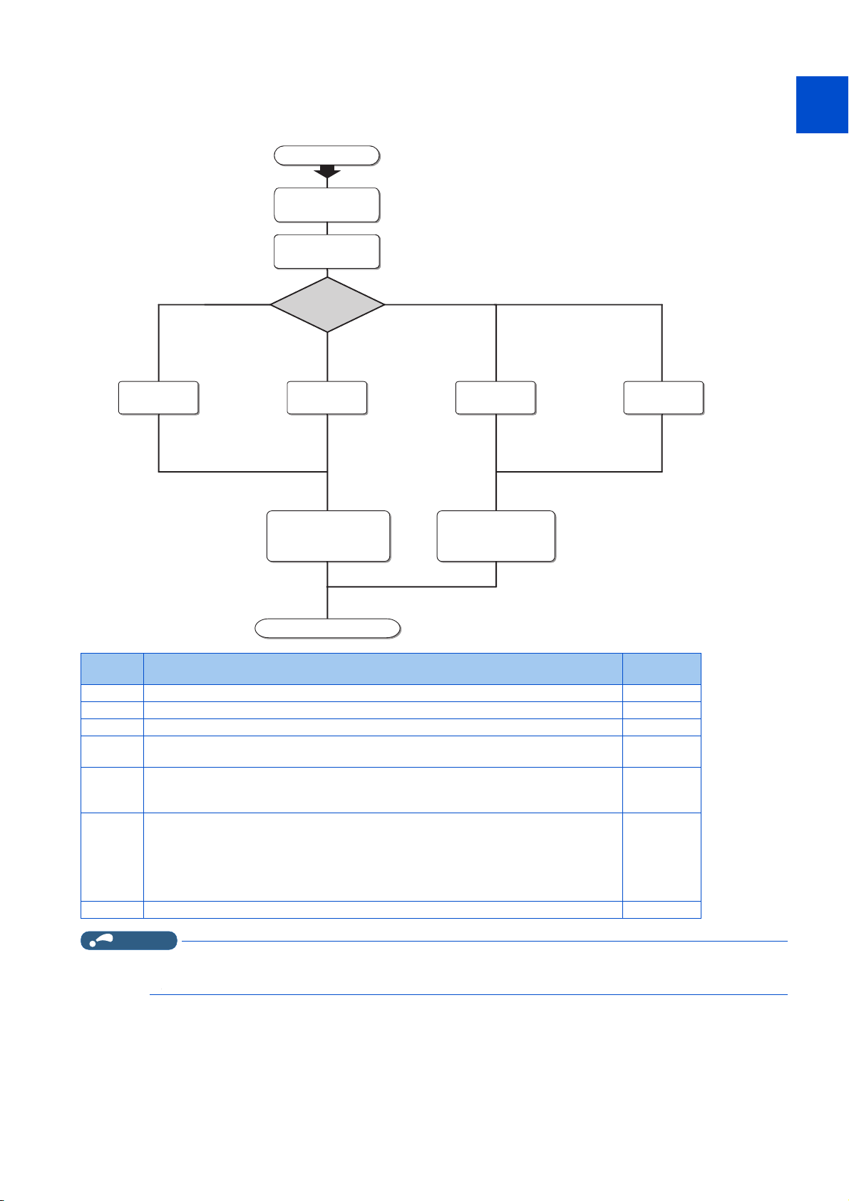
Setting check
USB connection
(c) (d) (d)
Set the operation
mode to PU operation
mode.
Type of
connection with
inverters
Connection using
PU connector
Operation steps
(a) Check the system
configuration
(b) Install
FR Configurator2
(g) Start FR Configurator2
Connection using
RS-485 terminal
Set the operation
mode to NET operation
mode.
Connection using
Ethernet
(e)
Check the following settings before configuring the inverter with this software. For the details of communication parameters,
refer to page 23.
1
2
3
4
5
6
7
Symbol Overview
(a) Check the system configuration 11
(b) Install FR Configurator2 19
(c) Set Pr.548 USB communication check time interval = "9999". 26
(d)
(e)
(f)
(g) Start FR Configurator2 57
NOTE
Initial parameter settings can be used. (Set Pr.122 PU communication check time interval
≠ "0" and Pr.123 PU communication waiting time setting = "9999".)
Set the station number in Pr.331 RS-485 communication station number (for multiple
connection). Set Pr.336 RS-485 communication check time interval ≠ "0" and Pr.337 RS-
485 communication waiting time setting = "9999".
• FR-A800-E/F800-E
Set the station number in Pr.1425 Ethernet communication station number (for multiple
connection). Set Pr.1432 Ethernet communication check time interval = "9999".
• FR-E700-NE
• The available connection methods differ depending on the inverter. For the details, refer to the Instruction Manual of the
Set the station number in Pr.831 Ethernet communication station number (for multiple
connection). Set Pr.852 Ethernet communication check time interval = "9999".
inverter.
Refer to
30
41
35
8
9
10
page
1. OUTLINE
1.1 Before using this software
9
Page 11

1.1.1 Product confirmation
After unpacking, check that the following items are contained in the package:
Item Quantity
DVD 1
Installation Manual 1
License certificate 1
1. OUTLINE
10
1.1 Before using this software
Page 12

1.2 System configuration
1
1.2.1 System requirement for FR Configurator2
Component
Personal
computer
Software Internet Explorer® 5.0 or later
Display
Keyboard Compatible with the above personal computer.
Mouse Compatible with the above personal computer.
Printer Compatible with the above personal computer.
*1
IBM PC/AT compatible machine with DVD drive (for installation), USB port or serial port
• Windows® 10 (Home, Pro, Enterprise, IoT Enterprise*3)
• Windows® 8.1, Windows® 8.1 (Pro, Enterprise)
*2
OS
Processor
Memory
Hard disk Free area of 1.5 GB or more
Applicable to display at resolution of 1024 × 768 or more, and 256 colors or more. Compatible with the above personal
computer.
*1 FR Configurator2 may not operate properly depending on the type of personal computer, peripheral devices, or software used.
*2 Operation on an operating system not listed here is not guaranteed.
*3 32-bit Edition is not supported.
*4 64-bit Edition is not supported.
• Windows® 8, Windows® 8 (Pro, Enterprise)
• Windows® 7 (Professional, Enterprise)
• Windows Vista®
• Windows® XP (Professional SP3 or later, Home Edition SP3 or later)
• Desktop PC: Intel® Celeron® Processor 2.8 GHz or higher
• Laptop PC: Intel® Pentium® M Processor 1.7 GHz or higher
• 2 GB or more: Windows® 10, Windows® 8.1, Windows® 8, Windows® 7 (64-bit Edition)
• 1 GB or more: Windows® 10, Windows® 8.1, Windows® 8, Windows® 7 (32-bit Edition)
• 512 MB or more (Windows Vista®)
• 128 MB or more (Windows® XP Professional, Windows® XP Home Edition)
*4
Description
*4
2
3
4
5
6
7
8
9
10
1. OUTLINE
1.2 System configuration
11
Page 13

1.2.2 Compatible inverters
FR Configurator2 is compatible with the following inverters.
800 series
Series Model Capacity Structure Function
FR-A820 00046(0.4K) to 04750(90K)
FR-A840 00023(0.4K) to 06830(280K)
FR-A842 07700(315K) to 12120(500K) Separated converter type
FR-A846 00023(0.4K) to 03610(132K) IP55 compatible model
FR-A860 00027(0.75K) to 04420(220K) Standard model
FR-A862 05450(280K) to 08500(450K) Separated converter type
FR-A800 series
FR-B series (A800
specification)
FR-B3 series (A800
specification)
FR-A800 Plus series
FR-F800 series
FREQROL-CS80 series
FR-A820-E 00046(0.4K) to 04750(90K)
FR-A840-E 00023(0.4K) to 06830(280K)
FR-A842-E 07700(315K) to 12120(500K) Separated converter type
FR-A846-E 00023(0.4K) to 03610(132K) IP55 compatible model
FR-A860-E 00027(0.75K) to 04420(220K) Standard model
FR-A862-E 05450(280K) to 08500(450K) Separated converter type
FR-A870-E 02300 to 02860 Standard model
FR-B (200V) 750 to 3700, 5.5K to 75K
FR-B (400V) 750 to 3700, 7.5K to 110K
FR-B3-(N)
FR-B3-(N)H
FR-A820-CRN 00046(0.4K) to 04750(90K)
FR-A842-CRN 07700(315K) to 12120(500K) Separated converter type
FR-A820-E-CRN 00046(0.4K) to 04750(90K)
FR-A840-E-CRN 00023(0.4K) to 06830(280K)
FR-A842-E-CRN 07700(315K) to 12120(500K) Separated converter type
FR-A820-R2R 00046(0.4K) to 04750(90K)
FR-A842-R2R 07700(315K) to 12120(500K) Separated converter type
FR-A820-E-R2R 00046(0.4K) to 04750(90K)
FR-A840-E-R2R 00023(0.4K) to 06830(280K)
FR-A842-E-R2R 07700(315K) to 12120(500K) Separated converter type
FR-A840-LC 03250(110K) to 06830(280K)
FR-A870-LC 03590(280K) to 04560(355K)
FR-A840-ELV 00126(3.7K) to 00770(30K) Elevator function
FR-F820 00046(0.75K) to 04750(110K)
FR-F840 00023(0.75K) to 06830(315K)
FR-F842 07700(355K) to 12120(560K) Separated converter type
FR-F846 00023(0.75K) to 03610(160K) IP55 compatible model
FR-F860 00680(45K) to 04420(250K) Standard model
FR-F862 05450(315K) to 08500(500K) Separated converter type
FR-F820-E 00046(0.75K) to 04750(110K)
FR-F840-E 00023(0.75K) to 06830(315K)
FR-F842-E 07700(355K) to 12120(560K) Separated converter type
FR-F846-E 00023(0.75K) to 03610(160K) IP55 compatible model
FR-F860-E 00027(1.5K) to 04420(250K) Standard model
FR-F862-E 05450(315K) to 08500(500K) Separated converter type
FR-CS84 012 to 295
FR-CS82S 025 to 100
400 to 3700, 5.5K to 37K
Standard model
Standard
Standard model
Standard (Ethernet
communication type)
Pressure-Resistant,
Explosion-Proof Motor
Standard model
Standard model
Standard model
Standard model
Standard model
Standard model
Standard model
Standard model Standard
Driving Inverter
Crane functionFR-A840-CRN 00023(0.4K) to 06830(280K)
Crane function (Ethernet
communication type)
Roll to Roll functionFR-A840-R2R 00023(0.4K) to 06830(280K)
Roll to Roll function
(Ethernet communication
type)
Liquid Cooled Type
Standard
Standard (Ethernet
communication type)
1. OUTLINE
12
1.2 System configuration
Page 14

700 series / 500 series
Series Model
FR-A720 0.4K to 90K 00030 to 03460 — —
A700 series
FR-B (A700) series
FR-B3 (A700) series
FR-F700 series
FR-F700P series
FR-E700 series
FR-D700 series
FR-E700EX series FR-E720EX 0.1K to 3.7K — — —
FR-E500 series FR-E560 — 0.75K to 7.5K — —
FR-A740 0.4K to 500K 00015 to 09620 00023 to 12120 0.4K to 500K
FR-A760 — 00017 to 06630 — —
FR-B (200V)
FR-B (400V)
FR-B3-(N)
FR-B3-(N)H — — —
FR-F720 0.75K to 110K 00046 to 04750 — —
FR-F740 0.75K to 560K 00023 to 12120 00023 to 12120
FR-F720P 0.75K to 110K — — —
FR-F740P 0.75K to 560K — — —
FR-E710W 0.1K to 0.75K 008 to 050 — —
FR-E720 0.1K(SC) to 15K(SC) 008(SC) to 600(SC) — —
FR-E720S 0.1K(SC) to 2.2K(SC) 008 to 110 008(SC) to 110(SC) 0.1K to 2.2K
FR-E740 0.4K(SC) to 15K(SC) 016(SC) to 300(SC) 016(SC) to 300(SC) 0.4K to 15K
FR-E720-NE 0.1K to 15K 008-SC to 600-SC — —
FR-E720S-NE 0.1K to 2.2K — 008-SC to 110-SC 0.1K to 2.2K
FR-E740-NE 0.4K to 15K 016-SC to 300-SC 016-SC to 300-SC 0.4K to 15K
FR-D710W 0.1K to 0.75K 008 to 042 — —
FR-D720 0.1K to 15K 008 to 318 — —
FR-D720S 0.1K to 2.2K 008 to 100 008(SC) to 100(SC) 0.1K to 2.2K
FR-D740 0.4K to 15K 012 to 160 012(SC) to 160(SC) 0.4K to 7.5K
Japan North America Europe China
750 to 3700, 5.5K to
75K
750 to 3700, 7.5K to
110K
400 to 3700, 5.5K to
37K
———
———
———
Capacity
1
2
3
4
S75K to S630K CHT, 0.75K to 55K CHT1
5
6
7
8
9
10
1. OUTLINE
1.2 System configuration
13
Page 15

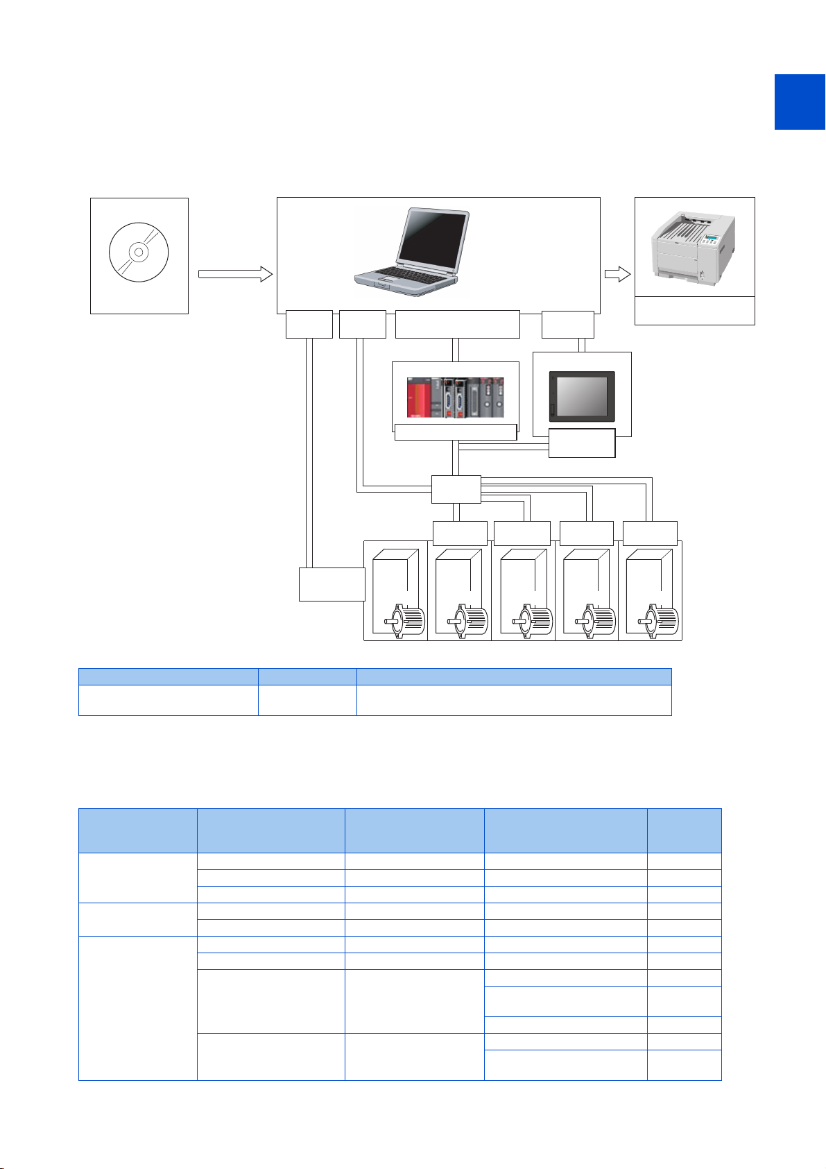
1.2.3 System configuration
Inverter
∗1
Converter
RS-485 cable
∗5
Serial
port
USB
connector
USB
connector
USB connector
PU
connector
FR Configurator2
Commercially available
printer
Connection cable
RS-485/RS-422
Multidrop link system
Inverter
Inverter
Inverter Inverter Inverter
RS-485
terminal
∗6
∗2
Converter
∗4
RS-485
terminal
RS-485
terminal
RS-485
terminal
RS-485
terminal
GOT1000/GOT2000
USB connector or
serial port
∗7
∗8
RS-422
communication unit
The following devices are required to use FR Configurator2. Set up the system in accordance with the Instruction Manual of
each device.
Example (USB communication / serial communication)
Refer to connection options on page 15 to configure the system.
1. OUTLINE
14
1.2 System configuration
*1 When using a serial port of a personal computer, a commercially available converter is required.
Examples of product available on the market (as of November 2013)
Model: DINV-CABV (with connectors and cable)
Diatrend Corp.
The converter cable cannot connect two or more inverters (the computer and inverter are connected on a 1:1 basis). This is an RS232C-to-RS485
converter-embedded conversion cable. No additional cable or connector is required. Contact a manufacturer for details of the product.
*2 Connection cable
Examples of product available on the market (as of February 2015)
Connector: RJ-45 connector
Example: Tyco Electronics
5-554720-3
Cable: Cable in compliance with EIA568 (such as 10BASE-T cable)
Example: Mitsubishi Cable Industries, Ltd.
SGLPEV-T (Cat5e/300m) 24AWG × 4P
*3 USB/RS-485 convert cable
Examples of product available on the market (as of February 2015)
Model: DINV-U4
Diatrend Corp.
Refer to page 63 for the communication setting with DINV-U4.
When using USB/RS-485 convert cable, use the newest driver software.
For a product details or the newest driver software, contact the cable manufacturer.
*4 Recommended USB cable for computer-inverter connection
MR-J3USBCBL3M (cable length: 3 m)
*5 Communication is available via the PU connector, RS-485 terminals, or USB connector.
*6 Maximum overall length of connection cable: 500 m
Page 16
*7 Select a USB connector or a serial port (one of the ports 1 to 63) on the communication setting window of FR Configurator2. (Multiple ports cannot
Inverter
Hub
USB connector, Serial port
or Ethernet connector
Ethernet
connector
FR Configurator2
Commercially available
printer
Inverter Inverter Inverter Inverter
Ethernet
connector
Ethernet
connector
Ethernet
connector
Ethernet
connector
Ethernet
connector
Ethernet
connector
QCPU/LCPU/RCPU
Programmable controller
∗2
Ethernet
connector
∗1
GOT2000
Ethernet
connector
Ethernet
connector
be used at the same time.) One personal computer is connected to one GOT. When using the USB for connecting a GOT, use a dedicated cable,
GT09-C30USB-5P or GT09-C20USB-5P. The GOT2000 series and a personal computer can be connected only via USB or Ethernet.
*8 For the GOT1000 series, an RS-422 communication unit (GT15-RS4-9S) is required. For the compatible version of GOT or details of the RS-422/
485 connection, refer to the GOT1000/GOT2000 Series Connection Manual.
1
Example (Ethernet communication)
Refer to connection options on page 15 to configure the system.
2
3
4
5
6
7
8
*1 When an Ethernet port is used on the computer, use a 1000BASE-T compliant Ethernet cable.
Ethernet cable Connector Standard
Category 5e or higher straight
cable (double shielded/STP)
*2 For the connection with the inverter using a programmable controller, refer to the Operating Manual of GX Works with the version applicable to
the programmable controller CPU.
RJ-45 connector
Use cables compliant with the following standards. IEEE 802.3
(1000BASE-T), ANSI/TIA/EIA-568-B (Category 5e)
Connection options
The following table shows connection options. Refer to the following schematic diagrams for connection examples.
Number of
connectable
inverters
One
Two or more
One, or two more
more
PC-side port Intermediate device Communication
USB Not connected USB 16, 26
Serial Not connected Serial 16, 30
Ethernet Not connected Ethernet 16, 35
Serial Not connected Serial 16, 41
Ethernet Not connected Ethernet 17, 35
USB or serial GOT1000 Serial 17, 43
USB or Ethernet GOT2000 Serial or Ethernet 17, 43
USB, serial, or Ethernet Programmable controller
USB
GOT2000 to
programmable controller
Ethernet 17, 50
CC-Link IE Field Network
communication
CC-Link IE TSN communication 18, 51
Ethernet 18, 50
CC-Link IE Field Network
communication
Refer to
page
18, 50
19, 50
9
10
1. OUTLINE
1.2 System configuration
15
Page 17
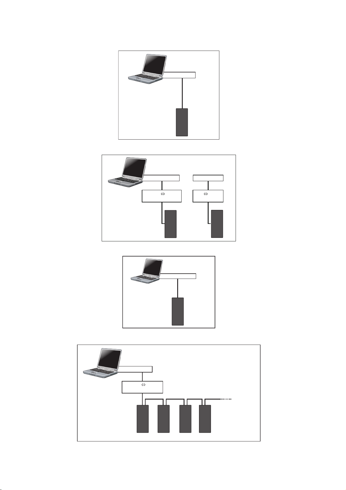
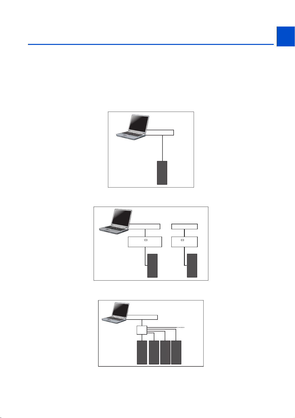
Refer to page 23 for details of connection between a personal computer (FR Configurator2) and inverters.
USB cable
Personal computer
(FR Configurator2)
Inverter
USB mini B
connector
USB connector
converter
Serial cable
Personal computer
(FR Configurator2)
Inverter
PU connector
RS-232C RS-485
Serial port or
USB connector
converter
USB cable
Inverter
PU connector
USB RS-485
Ethernet
cable
Personal computer
(FR Configurator2)
Inverter
Ethernet
connector
Ethernet connector
--
RS-232C RS-485
converter
Serial cable
RS-422 / 485
Up to
32 inverters
Personal computer
(FR Configurator2)
Inverter
RS-485 terminal block
Serial port
Direct connection of FR Configurator2 and an inverter (USB communication)
Direct connection of FR Configurator2 and an inverter (serial communication)
Direct connection of FR Configurator2 and an inverter (Ethernet communication)
Connection of FR Configurator2 and inverters (serial communication)
1. OUTLINE
16
1.2 System configuration
Page 18
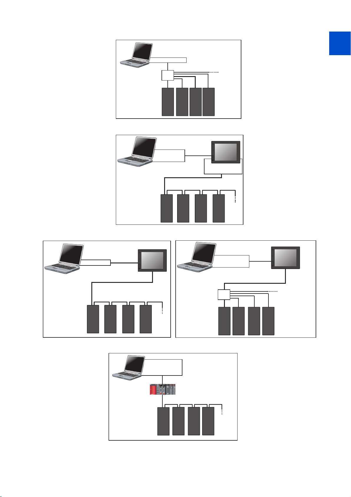
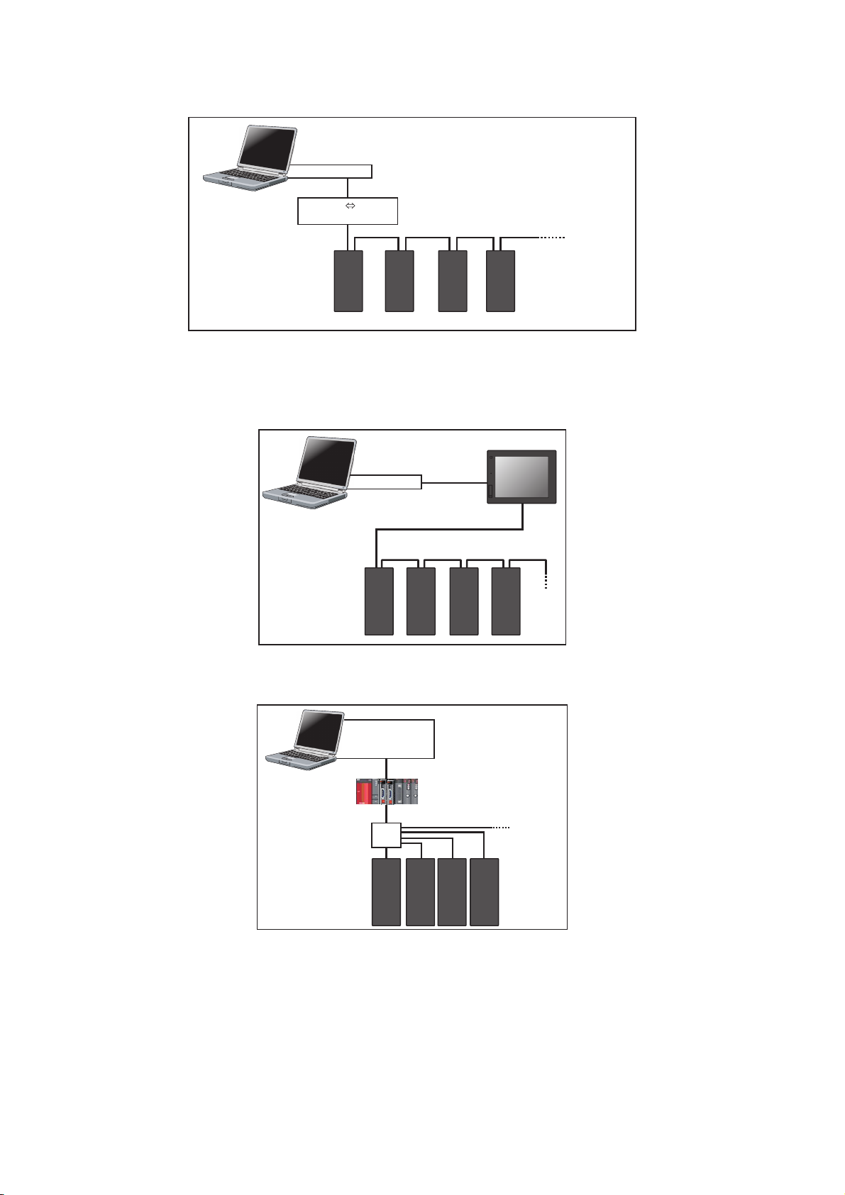
Connection of FR Configurator2 and inverters (Ethernet communication)
Ethernet
cable
Up to
120 inverters
Personal computer
(FR Configurator2)
Inverter
Ethernet
connector
Ethernet connector
Hub
GOT RS-422
GOT1000
communication unit
USB connector/
Serial port
USB/serial cable
RS-422
Up to 32 inverters can be connected.
RS-485 terminal block
Personal computer
(FR Configurator2)
GOT2000
USB connector/
Ethernet
connector
USB/
Ethernet
cable
Up to 120 inverters
can be connected.
Personal computer
(FR Configurator2)
GOT2000
RS-422/485
Up to 32 inverters can be connected.
Personal computer
(FR Configurator2)
USB cable
RS-485 terminal block
USB connector
Hub
Ethernet
connector
Inverter
Inverter
Ethernet
cable
Connection of FR Configurator2 and inverters via a GOT1000 model
1
2
3
4
5
6
7
Connection of FR Configurator2 and inverters via a GOT2000 model
Connection of FR Configurator2 and inverters via a programmable controller
USB connector,
Personal computer
(FR Configurator2)
Serial port
Ethernet connector
,
Programmable controller
(CPU unit,
Ethernet
unit)
8
9
10
CC-Link IE Field Network communication
Ethernet
connector
Inverter
Up to
120 inverters
1. OUTLINE
1.2 System configuration
17
Page 19
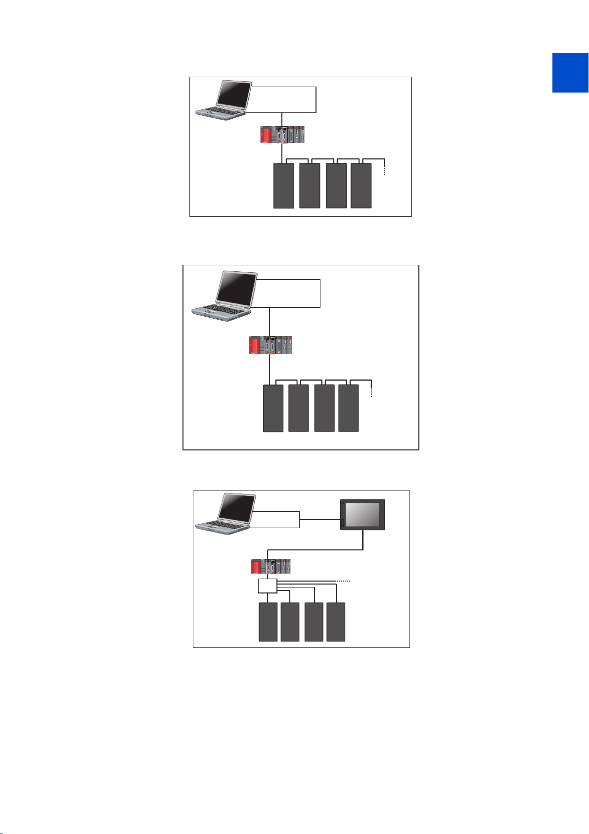
Connection of FR Configurator2 and inverters via a programmable controller (CC-Link IE Field
Personal computer
(FR Configurator2)
USB connector,
Serial port,
Ethernet connector
Programmable controller
(CPU unit, Ethernet unit)
Inverter
Ethernet
connector
CC-Link IE TSN communication
Up to 120
inverters
GOT2000
USB connector/
Serial port
USB/serial cable
Personal computer
(FR Configurator2)
Ethernet
connector
Inverter
Ethernet
cable
Hub
Programmable controller
(CPU unit,
Ethernet
unit)
Up to 64 or 120
inverters
Network communication)
USB connector,
Personal computer
(FR Configurator2)
Ethernet
connector
Inverter
Serial port
Ethernet connector
Hub
,
Programmable controller
(CPU unit,
Ethernet
cable
Ethernet
unit)
Up to 64 or
120 inverters
Connection of FR Configurator2 and inverters via a programmable controller (CC-Link IE TSN
communication)
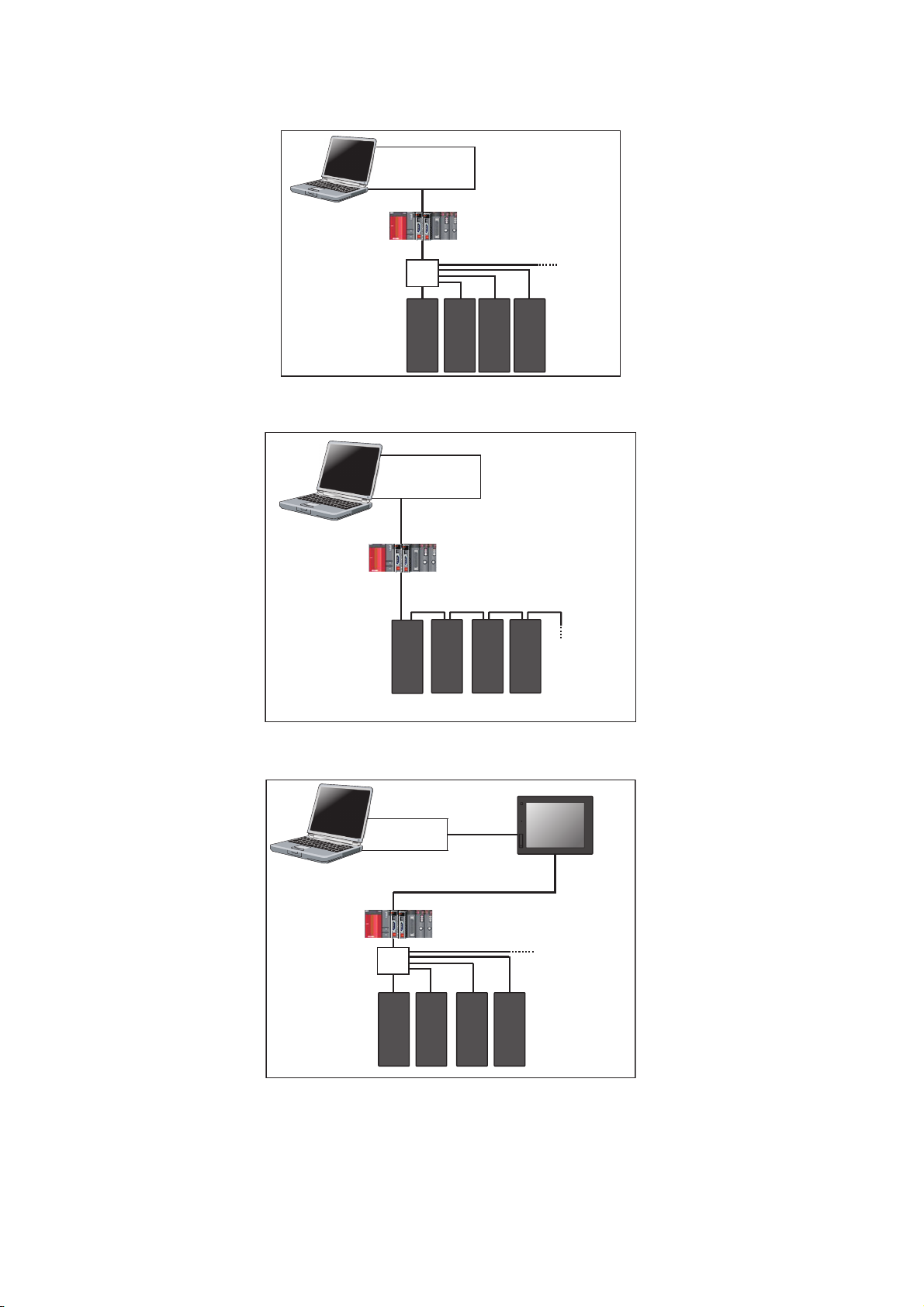
Connection of FR Configurator2 and inverters via a GOT2000 model and a programmable
controller
1. OUTLINE
18
1.2 System configuration
Page 20
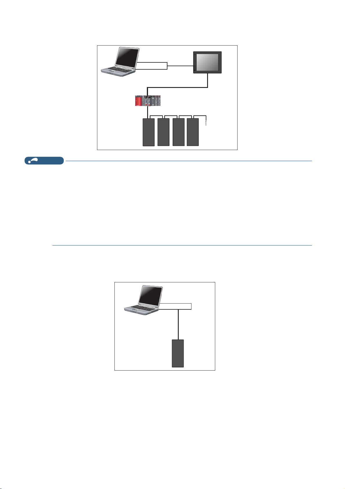
Connection of FR Configurator2 and inverters via a GOT2000 model and a programmable
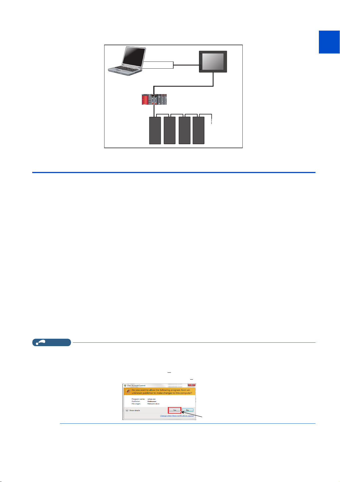
NOTE
Click "Yes"
controller (CC-Link IE Field Network communication)
GOT2000
USB cable
1
USB connector
Personal computer
(FR Configurator2)
Communication
connector
Inverter
Ethernet
cable
CC-Link IE Field Network communication
Up to
120 inverters
1.3 Installation and uninstallation
1.3.1 Installation of FR Configurator2
To use FR Configurator2, the files included on the setup disk (DVD) or the downloaded file must be installed onto the personal
computer.
Check the following points before the installation.
2
3
4
5
6
7
8
• Close any other applications that have already been running.
• For the installation, log on as an administrator (Administrator account) and start installation.
• If an inverter is connected by the USB cable, disconnect the USB cable.
• Installation files are compressed. Copying the files does not start FR Configurator2 yet. Install the software using the setup
program.
• To install the software, follow the installation procedure in Windows screen.
• In an operation system with antivirus/security software, a warning may appear when installing FR Configurator2. If a
warning appears, permit the installation of FR Configurator2 according to the setting procedure of your antivirus/security
software.
Installation procedure
The following section describes the procedures of installing FR Configurator2.
1. Insert the DVD to an available DVD drive. Installation starts automatically.
• Installation can be started by double-clicking the icon of DVD drive or the following procedure.
1) Choose the [Run...] command from [Start] menu.
2) "Run" window appears.
3) Type "D:\SETUP" (with one-byte characters) in "O
• The following dialog may appear during the installation. Click “Y
pen" field and click [OK]. (When DVD drive is D drive.)
es".
9
10
1. OUTLINE
1.3 Installation and uninstallation
19
Page 21
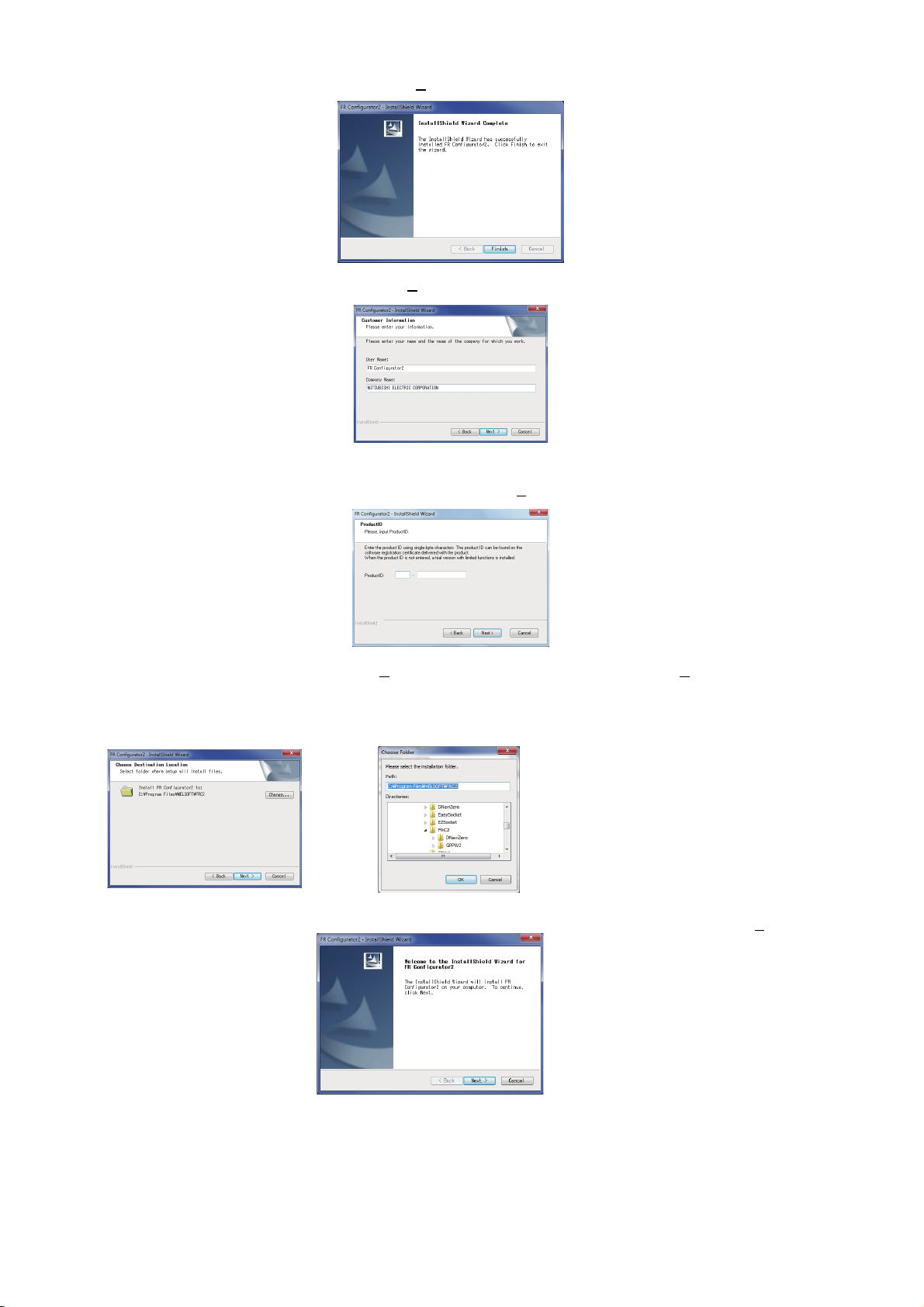
2. The following window will be displayed. Click [Next>].
3. Enter user name and company name. Click [Next>] after entering.
4. Enter the product ID using single-byte numeric characters. The product ID can be found on the license certificate
delivered with the product. After entering the product ID, click [Next>].
5. Check the installation folder and click [Next>]. To change the installation folder, click [Change...] and select an
installation folder. A new folder "FRC2" is created at the selected installation folder. This software is installed there.
(If the installation folder is not changed, the software is installed at "C:\Program Files\MELSOFT\FRC2")
6. Check that the setting is correct and click [Install]. Installation will start. To change the setting, click [<Back].
1. OUTLINE
20
1.3 Installation and uninstallation
Page 22
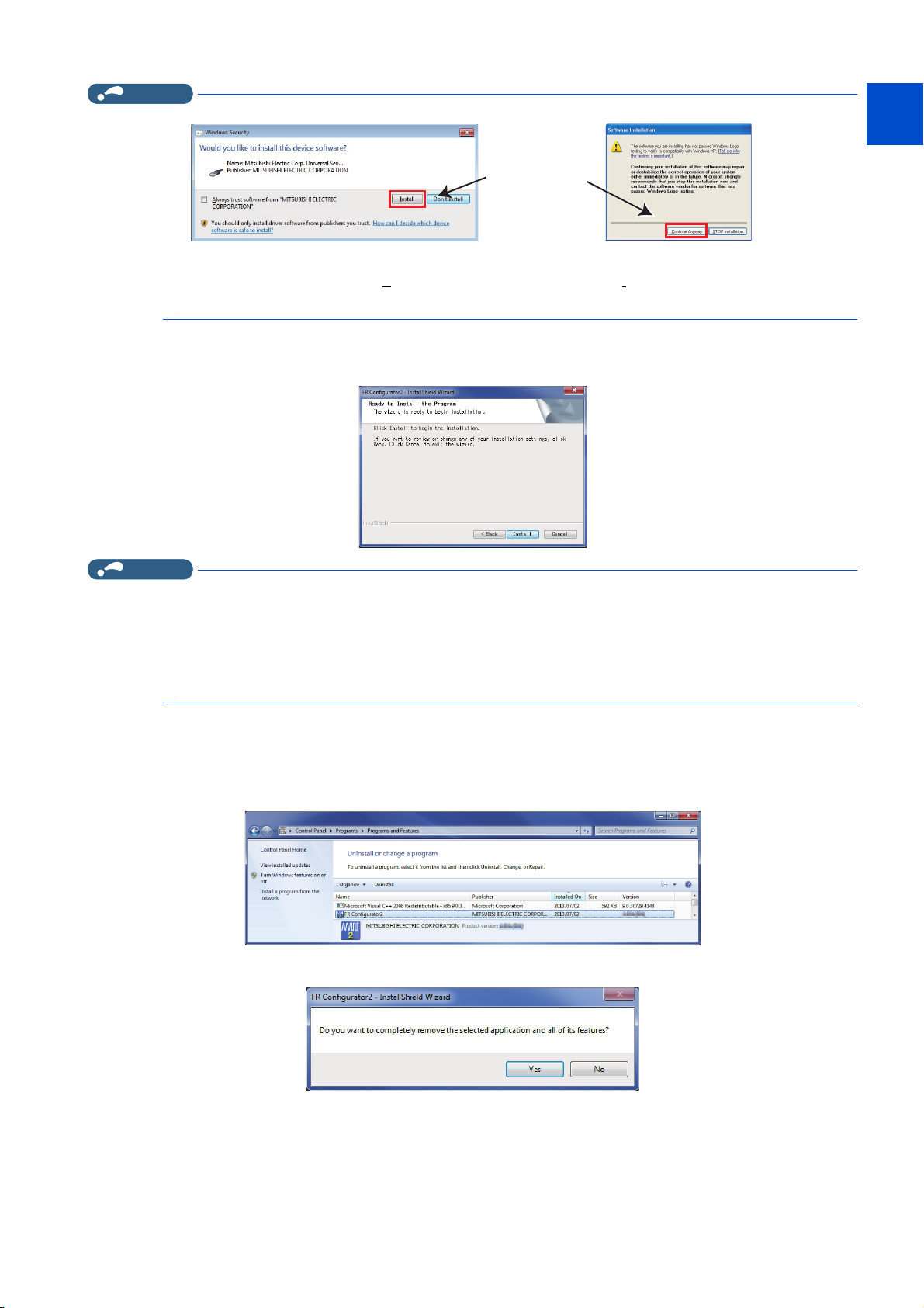
NOTE
• The following window may appear during the installation.
For Windows® XPFor Windows Vista® or Windows® 7
Click and continue
1
2
3
• Continue the installation by clicking [C
Windows® 8, Windows® 8.1, Windows® 10.
ontinue Anyway] for Windows® XP and "Install" for Windows Vista®, Windows® 7,
7. Installation is completed. Click [Finish] to close the window. Restart the personal computer before using the
software.
NOTE
• The "Program Compatibility Assistant" dialog may appear when completing the installation. If the dialog appears, select "This
program installed correctly".
• If the user is not an administrator (Administrator account), the installation cannot be performed. Log in as a user with
administrator permission, and start the installation again.
• When .NET Framework (version 3.5, 3.0, or 2.0) is disabled, the installation is not completed. Enable .NET Framework (version
3.5, 3.0, or 2.0) and try the installation again.
4
5
6
7
8
9
10
1.3.2 Uninstallation of FR Configurator2
Open the [Start] menu of Windows, and then click [Control Panel]. Click [Programs] in the "Control Panel" window.
When "Programs and Features" window is displayed, select "FR Configurator2" to start uninstallation.
When the uninstallation starts, the following confirmation dialog appears.
1. OUTLINE
1.3 Installation and uninstallation
21
Page 23

Click [Yes] to proceed the uninstallation. (Click [No] to cancel the uninstallation.) The following window is displayed when the
NOTE
uninstallation is completed. Click [Finish] to close the window.
• Uninstallation is unavailable while the application is running. Perform the uninstallation after closing the application.
• For Windows® XP, uninstall the software as follows.
1. Select [Control panel] on the start menu and display the "Add or Remove Programs" window.
2. Select FR Configurator2 and click the [Delete] button.
• For Windows® 8, uninstall the software as follows.
1. Select [Control Panel] from the All Apps list and display Uninstall or change a program.
2. Select FR Configurator2 and click the [Delete] button.
• For Windows® 10, uninstall the software as follows.
1. Right click the Start button to select [Control Panel], and display Uninstall or change a program. Or click [Settings] ->
[System] on the Start menu and select Apps & features.
2. Select FR Configurator2 and click the [Delete] button.
1. OUTLINE
22
1.3 Installation and uninstallation
Page 24
1.4 Connection and parameter setting
Ethernet
cable
Up to
120 inverters
Personal computer
(FR Configurator2)
Inverter
Ethernet
connector
Ethernet connector
Hub
1
1.4.1 Connection method
For FR Configurator2, communication via a USB connector, a PU connector, the RS-485 terminal block, Ethernet, a GOT, or
a programmable controller is available. USB connection is initially selected.
• USB connection (Refer to page 26.)
Connect to USB connector (mini B connector) of the inverter. 1:1 connection is supported. Connection with using USB hub
is not supported.
USB connector
Personal computer
(FR Configurator2)
Inverter
• Serial communication (PU connector) (Refer to page 30.)
Connect to PU connector of the inverter. Serial port/RS-485 converter (cable) or USB/RS-485 converter (cable) is required.
USB cable
USB mini B
connector
2
3
4
5
6
7
8
9
Serial port or
Personal computer
(FR Configurator2)
• Ethernet connection (Ethernet connector) (Refer to page 35.)
Connection to the Ethernet connector of the inverter. Up to 120 inverters can be connected using a hub.
RS-232C RS-485
PU connector
Inverter
Serial cable
converter
USB connector
USB RS-485
converter
PU connector
Inverter
USB cable
1.4 Connection and parameter setting
1. OUTLINE
10
23
Page 25
• Serial communication (RS-485 terminal) (Refer to page 41.)
Connect to RS-485 terminal of the inverter. Up to 32 inverters can be connected.
converter
Serial cable
RS-422 / 485
Up to
32 inverters
Personal computer
(FR Configurator2)
RS-485 terminal block
RS-232C RS-485
Inverter
Serial port
--
• Communication through GOT (USB / Serial communication) (Refer to page 43.)
Through a GOT (Human Machine Interface), connection to the RS-485 terminal block is available. For the GOT1000
series, an RS-422 communication unit is required. For the compatible version of GOT or details of the RS-422/485
connection, refer to the GOT1000/GOT2000 Series Connection Manual.
GOT2000
USB connector
Personal computer
(FR Configurator2)
Up to 32 inverters can be connected.
RS-485 terminal block
USB cable
RS-422/485
• Communication using programmable controller (Ethernet communication) (Refer to page 50.)
A programmable controller (CPU module / Ethernet module) can be used for connecting the inverter.
USB connector,
Personal computer
(FR Configurator2)
Ethernet
connector
Inverter
Serial port
Ethernet connector
Hub
,
Programmable controller
(CPU unit,
Ethernet
cable
Ethernet
unit)
Up to 64 or
120 inverters
1. OUTLINE
24
1.4 Connection and parameter setting
Page 26
• Communication using programmable controller (CC-Link IE Field Network communication) (Refer to page 50.)
GOT2000
USB connector/
Serial port
USB/serial cable
Personal computer
(FR Configurator2)
Ethernet
connector
Inverter
Ethernet
cable
Hub
Programmable controller
(CPU unit,
Ethernet
unit)
Up to 64 or 120
inverters
A programmable controller (CPU module / Ethernet module) can be used for connecting the inverter.
USB connector,
Personal computer
(FR Configurator2)
Serial port
Ethernet connector
,
Programmable controller
(CPU unit,
Ethernet
unit)
1
2
CC-Link IE Field Network communication
Ethernet
connector
Inverter
Up to
120 inverters
• Communication using programmable controller (CC-Link IE TSN communication)
(Refer to page 51.)
A programmable controller (CPU module / Ethernet module) can be used for connecting the inverter.
USB connector,
Personal computer
(FR Configurator2)
Ethernet
connector
Inverter
Serial port,
Ethernet connector
Programmable controller
(CPU unit, Ethernet unit)
CC-Link IE TSN communication
Up to 120
inverters
3
4
5
6
7
8
9
• Communication through GOT and programmable controller (Ethernet communication) (Refer to page 50.)
Through a GOT (Human Machine Interface) and a programmable controller, connection to the inverter is available.
10
1.4 Connection and parameter setting
1. OUTLINE
25
Page 27
• Communication through GOT and programmable controller (CC-Link IE Field Network communication) (Refer to page 50.)
NOTE
GOT2000
USB connector
USB cable
Personal computer
(FR Configurator2)
Communication
connector
Inverter
Ethernet
cable
Up to
120 inverters
CC-Link IE Field Network communication
Through a GOT (Human Machine Interface) and a programmable controller, connection to the inverter is available.
• Inserting or pulling out a USB cable during FR Configurator2 operation may cause the inverter to be unrecognized.
Insert and pull out the USB cable for several times, or reset the inverter with the USB cable connected to the personal
computer.
•If Pr.999 Automatic parameter setting is changed to "10 or 11" using the operation panel, parameter unit, etc. during FR
Configurator2 operation, the inverter communication parameters will be changed, and such setting may disable the
communication with FR Configurator2. (For Pr.999, refer to the Instruction Manual (Detailed) of the inverter.)
• Only the USB connection is available for connecting a GOT2000 model to a personal computer.
• The USB driver must be installed for USB communication with the programmable controller CPU. For installing the driver, refer
to the Operating Manual of GX Works with the version applicable to the programmable controller CPU.
• The available connection methods differ depending on the inverter. For the details, refer to the Instruction Manual of the
inverter.
1.4.2 Connection using USB connector
A personal computer and inverter can be easily connected with USB cable. 1:1 connection is supported. Connection using USB
hub is not supported.
Personal computer
(FR Configurator2)
Inverter
USB connector
USB cable
USB mini B
connector
1. OUTLINE
26
1.4 Connection and parameter setting
Page 28

800 series
USB host
(A connector)
USB device
(mini B connector)
Communication
status LED
USB cable
USB connector
Place a flathead screwdriver, etc.
in a slot and push up the cover to open.
Removal of cover
Connect the USB cable to the USB device (mini B connector) on the inverter.
1
2
3
FR-A700, FR-B (700), and FR-B3 (700)
FR-E700 and FR-E700EX
USB cable
USB connector
4
5
6
7
8
9
10
• Applicable cable
Interface Conforms to USB 1.1
Transmission speed 12 Mbps
Wiring length Maximum 5 m
Connector
Recommended USB cable MR-J3USBCBL3M (cable length 3 m)
800 series, FR-E700, and FR-E700EX USB mini B connector (receptacle)
FR-A700, FR-B (700), and FR-B3 (700) USB B connector (B receptacle)
How to open the USB connector cover
Pull the cover in the direction of arrow. Then turn it upward.
1.4 Connection and parameter setting
1. OUTLINE
27
Page 29

Related parameters for USB connection
NOTE
Set the following communication parameter when connecting the USB connector of the inverter. When performing parameter
writing or run command input, set the following command source parameters, and switch the operation mode to PU operation
mode.
Inverter
FR-A800(-E)
FR-B
FR-B3
FR-F800(-E)
FR-A700
FR-E700(SC)(NC)
FR-E700EX
FR-B (700)
FR-B3 (700)
• Set a station number of each inverter in Pr.547 USB communication station number. Perform inverter reset after setting the
parameter.
Communication parameter Command source parameter
Pr.548 USB communication check time
interval = "9999" (initial value)
Pr.548 USB communication check time
interval ≠ "0" (initial value: "9999")
Related parameter list
•800 series
Pr. Name
*1
547
N040
548
N041
551
D013
USB communication station number 0 0 to 31 Inverter station number specification.
*1
USB communication check time interval 9999
*2*3
PU mode operation command source
selection
Parameter setting
Pr.551 PU mode operation
command source selection = "3 or
9999" (initial value: "9999")
Pr.551 PU mode operation
command source selection = "3 or
9999" (initial value: "9999")
Pr.551 PU mode operation
command source selection = "3"
(initial value: "2")
Initial
value
9999
Setting range Description
0
0.1 to 999.8 s
9999 No communication check
1
2
3
5
9999
Operation
mode
PU
USB communication is available, but the inverter
output is shut off (E.USB) when the mode changes to
the PU operation mode.
Set the communication check time interval.
If a no-communication state persists for the
permissible time or longer, the inverter output is shut
off (E.USB).
RS-485 terminals are the command interface enabled
in the PU operation mode.
The PU connector is the command interface enabled
in the PU operation mode.
The USB connector is the command interface enabled
in the PU operation mode.
The Ethernet connector is the command interface
enabled in the PU operation mode.
USB automatic recognition
Basically, the operation panel (PU connector) is the
command interface. When the USB connector is used,
it is the command interface.
*1 Changed settings are enabled at the next power-ON or inverter reset.
*2 Pr. 551 is always write-enabled.
*3 The setting range depends on the inverter. For the details, refer to the Instruction Manual of the inverter.
1. OUTLINE
28
1.4 Connection and parameter setting
Page 30
•700 series
Pr. Name
*1
547
548
551
USB communication station number 0 0 to 31 Inverter station number specification.
*1
USB communication check time interval 9999
PU mode operation command source
*2*3
selection
*1 Changed settings are enabled at the next power-ON or inverter reset.
*2 Pr.551 can be always written regardless of the operation mode.
*3 The initial value and the setting range differ depending on the inverter. For the details, refer to the Instruction Manual of the inverter.
NOTE
• Always reset the inverter after making the setting of the parameters. After you have changed the communication-related
parameters, communication cannot be established until the inverter reset.
Initial
value
9999
Setting range Description
0
0.1 to 999.8 s
9999 No communication check
1
2
3
4
9999
USB communication is possible. Trips in the PU
operation mode (E.USB)
Set the communication check time interval.
If a no-communication state persists for the
permissible time or longer, the inverter output is shut
off (E.USB).
The RS-485 terminals are the command interface
enabled in the PU operation mode.
The PU connector is the command interface enabled
in the PU operation mode.
The USB connector is the command interface enabled
in the PU operation mode.
The operation panel is the command interface
enabled in the PU operation mode.
USB automatic recognition
Basically, the operation panel (PU connector) is the
command interface. When the USB connector is used,
it is the command source.
1
2
3
4
5
6
7
8
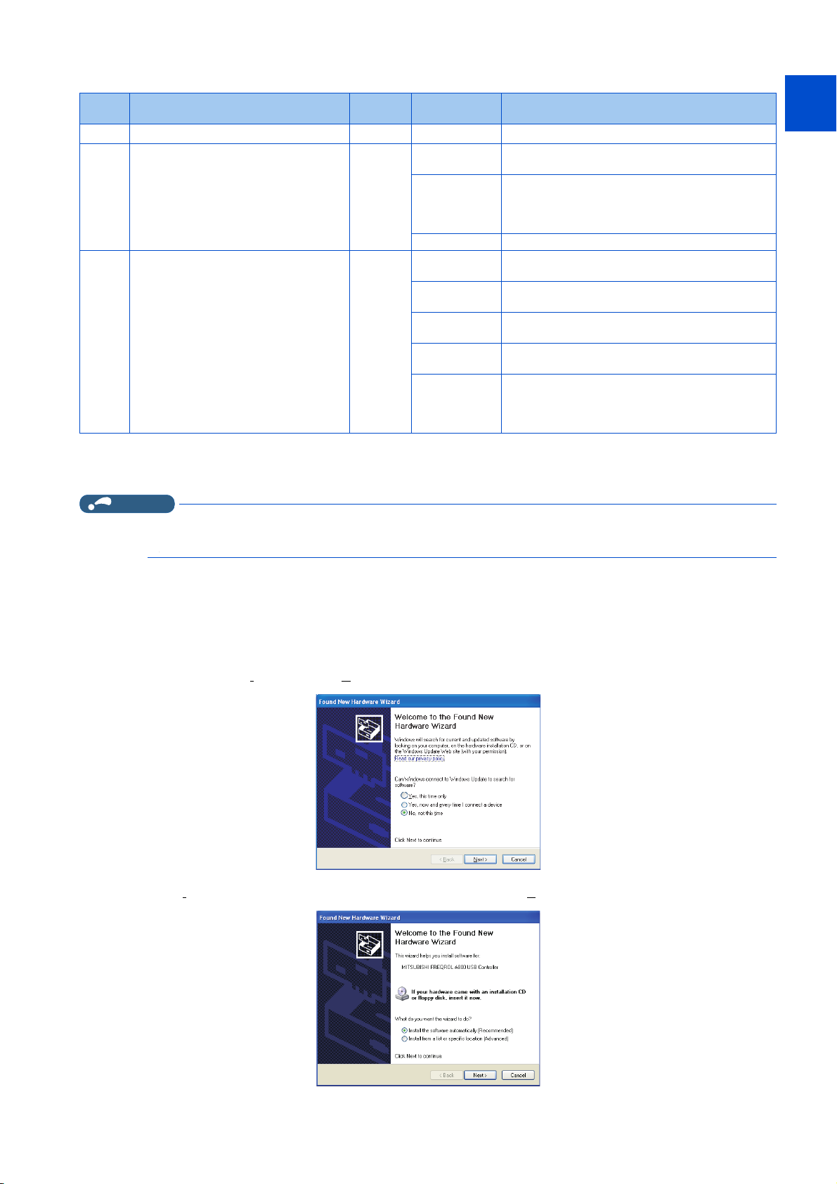
When connecting USB for the first time
If a personal computer and inverter are connected via USB for the first time with the inverter power ON, "Found New Hardware
Wizard" window is displayed.
The following additional wizard is displayed for Windows® XP.
1. Select "No, not this time", and click [Next].
2. Select "Install the software automatically (Recommended)" and click [Next].
9
10
1. OUTLINE
1.4 Connection and parameter setting
29
Page 31

3. If the following dialog box appears, click [Continue Anyway] to start the installation.
converter
Serial cable
Personal computer
(FR Configurator2)
Inverter
PU connector
RS-232C RS-485
Serial port or
USB connector
converter
USB cable
Inverter
PU connector
USB RS-485
4. The installation of the driver is completed. Click [Finish] to close the window.
1.4.3 Connection using PU connector
PU connector is used for connecting with a computer. Serial port/RS-485 converter (cable) or USB/RS-485 converter (cable)
is required.
1. OUTLINE
30
1.4 Connection and parameter setting
Page 32

PU connector pin layout
81
Inverter
(receptacle)
Front view
Inverter
(receptacle)
bottom view
81
Inverter
(receptacle)
Front view
81
800 series
FR-A700, FR-B (700), FR-B3 (700), FR-F700, and FR-F700P
(receptacle)
Front view
8
1
1
2
3
4
5
6
Inverter
7
8
FR-D700
FR-E700 and FR-E700EX
9
10
1. OUTLINE
1.4 Connection and parameter setting
31
Page 33

NOTE
NOTE
Pin number Name Description
1 SG Earth (ground) (connected to terminal 5)
2 — Operation panel power supply
3 RDA Inverter receive+
4 SDB Inverter send-
5 SDA Inverter send+
6 RDB Inverter receive-
7 SG Earth (ground) (connected to terminal 5)
8 — Operation panel power supply
• Refer to the following when fabricating the cable on the user side.
Commercially available product example (as of February 2015)
Product name Type Manufacturer
10BASE-T cable SGLPEV-T (Cat5e/300 m)
24AWG × 4P
RJ-45 connector 5-554720-3 Tyco Electronics
*1 Do not use pins No. 2 and 8 of the communication cable.
• A distributor is necessary for multiple connection.
Refer to the relevant Instruction Manual for multiple connection.
• Pins No. 2 and 8 provide power to the operation panel or parameter unit. Do not use these pins for RS-485 communication.
(Refer to the inverter Instruction Manual for details.)
• Do not connect the PU connector to the computer's LAN board, FAX modem socket or telephone modular connector. The
product could be damaged due to differences in electrical specifications.
*1
Mitsubishi Cable Industries, Ltd.
Related parameters for connection using PU connector
Set the following communication parameter when connecting PU connector of the inverter.
When performing parameter writing or run command input, set the following command source parameters, and switch the
operation mode to the following operation mode.
Inverter
FR-A800(-E)
FR-B
FR-B3
FR-F800(-E)
FR-CS80
FR-A700
FR-B (700)
FR-B3 (700)
FR-F700
FR-F700P
FR-E500
FR-E700
FR-E700EX
FR-D700 — Unchanged from the initial value. NET
• Set 3 s or more (or 9999) in Pr.122 PU communication check time interval.
• Set a station number of each inverter in Pr.117 PU communication station number for multiple connection. Perform inverter
Communication
option
—
— Unchanged from the initial value. PU
Not connected Unchanged from the initial value. NET
Connected
reset after setting the parameter.
Communication parameter Command source parameter
Pr.123 PU communication waiting time
setting ≠ "0"
Pr.123 PU communication waiting time
setting = "9999 (initial value)"
Parameter setting
Pr.551 PU mode operation
command source selection = "2 or
9999" (initial value: 9999)
Pr.551 PU mode operation
command source selection = "2"
(initial value: "9999")
Operation
mode
PU
PU
1. OUTLINE
32
1.4 Connection and parameter setting
Page 34

Related parameter list
•800 series
Pr. Name
117
N020
118
N021
N022 PU communication data length 0
N023 PU communication stop bit length 1
119
120
N024
122
N026
123
N027
551
D013
PU communication station number 0 0 to 31
PU communication speed 192
PU communication stop bit length / data
length
PU communication parity check 2
PU communication check time interval 9999
PU communication waiting time setting 9999
*1*2
PU mode operation command source
selection
Initial
value
1
9999
Setting range Description
Inverter station number specification.
Set the inverter station numbers when two or more
inverters are connected to one personal computer.
Set the communication speed.
48, 96, 192,
384, 576, 768,
1152
0 Data length 8 bits
1 Data length 7 bits
0 Stop bit length 1 bit
1 Stop bit length 2 bits
0 Stop bit length 1 bit
1 Stop bit length 2 bits
10 Stop bit length 1 bit
11 Stop bit length 2 bits
0 Without parity check
1 With parity check at odd numbers
2 With parity check at even numbers
0 PU connector communication is disabled.
0.1 to 999.8 s
9999 No communication check (signal loss detection)
0 to 150 ms
9999 Set with communication data.
1
2
3
4
5
9999
The setting value × 100 equals the communication
speed.
For example, if 192 is set, the communication speed is
19200 bps.
Data length 8
bits
Data length 7
bits
Set the communication check time interval.
If a no-communication state persists for the
permissible time or longer, the inverter output is shut
off. (The operation depends on the Pr.502 setting.)
Set the delay between data transmission to the
inverter and response.
RS-485 terminals are the command interface enabled
in the PU operation mode.
The PU connector is the command interface enabled
in the PU operation mode.
The USB connector is the command interface enabled
in the PU operation mode.
The operation panel is the command interface enabled
in the PU operation mode.
The Ethernet connector is the command interface
enabled in the PU operation mode.
USB automatic recognition
Basically, the operation panel (PU connector) is the
command interface. When the USB connector is used,
it is the command interface.
1
2
3
4
5
6
7
8
9
10
*1 Pr. 551 is always write-enabled.
*2 The setting range depends on the inverter. For the details, refer to the Instruction Manual of the inverter.
1.4 Connection and parameter setting
1. OUTLINE
33
Page 35

•700 series
NOTE
Pr. Name
117 PU communication station number 0 0 to 31
118 PU communication speed 192 48, 96, 192, 384
119
120 PU communication parity check 2
122 PU communication check time interval 9999
123 PU communication waiting time setting 9999
551
PU communication stop bit length / data
length
PU mode operation command source
*1*2
selection
Initial
value
1
9999
Setting range Description
0 Stop bit length 1 bit
1 Stop bit length 2 bits
10 Stop bit length 1 bit
11 Stop bit length 2 bits
0 Without parity check
1 With parity check at odd numbers
2 With parity check at even numbers
0 PU connector communication is disabled.
0.1 to 999.8 s
9999 No communication check (signal loss detection)
0 to 150 ms
9999 Set with communication data.
1
2
3
4
5
9999
Inverter station number specification.
Set the inverter station numbers when two or more
inverters are connected to one personal computer.
Set the communication speed.
The setting value × 100 equals the communication
speed.
For example, if 192 is set, the communication speed is
19200 bps.
Data length 8
bits
Data length 7
bits
Set the communication check time interval.
If a no-communication state persists for longer than
the permissible time, the inverter output will be shut
off. (The operation depends on the Pr.502 setting.)
Set the waiting time between data transmission to the
inverter and response.
The RS-485 terminals are the command interface
enabled in the PU operation mode.
The PU connector is the command interface enabled
in the PU operation mode.
The USB connector is the command interface in the
PU operation mode.
The operation panel is the command interface enabled
in the PU operation mode.
The Ethernet connector is the command interface in
the PU operation mode.
USB automatic recognition
Basically, the operation panel (PU connector) is the
command interface. When the USB connector is used,
it is the command interface.
*1 Pr.551 can be always written regardless of the operation mode.
*2 The setting range depends on the inverter. For the details, refer to the Instruction Manual of the inverter.
• Always reset the inverter after making the setting of the parameters. After you have changed the communication-related
parameters, communication cannot be established until the inverter reset.
• To change an inverter parameter value, use the operation panel or parameter unit. Only one of the operation unit and FR
Configurator2 (personal computer) can be connected to the PU connector.
• For details on each inverter communication parameter, refer to the Instruction Manual (Detailed) of the inverter.
• Parameter clear/All parameter clear by the operation panel or the parameter unit clears communication parameter settings
and disables the communication with FR Configurator2.
1. OUTLINE
34
1.4 Connection and parameter setting
Page 36

1.4.4 Connection of inverter via Ethernet
Ethernet
cable
Up to
120 inverters
Personal computer
(FR Configurator2)
Inverter
Ethernet
connector
Ethernet connector
Hub
Use the Ethernet connector on the Ethernet model inverter's Ethernet board for connection with a personal computer. Up to
120 inverters can be connected using a hub. An example of the connection procedure is shown on page 155.
1
2
3
4
Unpack the product and check the rating plate and the capacity plate of the inverter to ensure that the model agrees with the
order and the product is intact.
Related parameters for connection using Ethernet connector
Set the following communication parameters for connection using the inverter's Ethernet connector. To set parameters or input
operation commands, use the following parameters to set the following operation modes.
Inverter
FR-A800-E
FR-F800-E
FR-A800-ER2R
FR-E700-NE —
Communication
option
Not connected
Connected
Not connected
Connected
Communication parameter Command source parameter
Set the station number of each inverter in
Pr.1425 Ethernet communication station
number (for multiple connection).
Pr.1432 Ethernet communication check
time interval = "9999 (initial value)"
Set the station number of each inverter in
Pr.1074 Ethernet communication station
number (for multiple connection).
Pr.1432 Ethernet communication check
time interval = "9999 (initial value)"
Set the station number of each inverter in
Pr.831 Ethernet communication station
number (for multiple connection)
Pr.852 Ethernet communication check time
interval = "9999"
Parameter setting
Pr.550 NET mode operation
command source selection= "5"
(initial value: "9999")
Pr.551 PU mode operation command
source selection= "5" (initial value:
"9999")
Pr.550 NET mode operation
command source selection = "5"
(initial value: "9999")
Pr.551 PU mode operation command
source selection = "5" (initial value:
"9999")
Pr.550 NET mode operation
command source selection = "0"
(initial value: "0")
Operation
mode
NET
PU
NET
PU
NET
5
6
7
8
9
10
List of related parameters
• FR-A800-E and FR-F800-E
Pr. Name
550
D012
NET mode operation command source
selection
Initial
value
9999
Setting range
0
5
9999
Description
The communication option is the command interface
enabled in the NET operation mode.
The Ethernet connector is the command interface
enabled in the NET operation mode.
Communication option is recognized automatically.
Basically, the RS-485 terminals are the command
interface. When the communication option is installed,
the communication option is the command interface.
1. OUTLINE
1.4 Connection and parameter setting
35
Page 37

Pr. Name
551
D013
1434
N600
1435
N601
1436
N602
1437
N603
1438
N610
1439
N611
1440
N612
1441
N613
1427
N630
1428
N631
1429
N632
1426
N641
1455
N642
1431
N643
PU mode operation command source
selection
Ethernet IP address 1 192 0 to 255
Ethernet IP address 2 168 0 to 255
Ethernet IP address 3 50 0 to 255
Ethernet IP address 4 1 0 to 255
Subnet mask 1 255 0 to 255
Subnet mask 2 255 0 to 255
Subnet mask 3 255 0 to 255
Subnet mask 4 0 0 to 255
Ethernet function selection 1 5001
Ethernet function selection 2 45237
Ethernet function selection 3 9999
Link speed and duplex mode selection 0 0 to 4
Keepalive time 3600s 1 to 7200s
Ethernet signal loss detection function
selection
Initial
value
9999
0
Setting range
2
3
5
9999
502, 5000 to
5002, 5006 to
5008, 5010 to
5013, 9999,
45237, 61450
502, 5000 to
5002, 5006 to
5008, 5010 to
5013, 9999,
45237, 61450
502, 5000 to
5002, 5006 to
5008, 5010 to
5013, 9999,
45237, 61450
0
1 A warning (EHR) is output
2 A warning (EHR) and the
3 A protective function
The PU connector is the command interface enabled
in the PU operation mode.
The USB connector is the command interface in the
PU operation mode.
The Ethernet connector is the command interface in
the PU operation mode.
USB automatic recognition
Basically, the operation panel (PU connector) is the
command interface. When the USB connector is used,
it is the command interface.
Enter the IP address of the inverter to be connected to
Ethernet.
Enter the subnet mask of the network to which the
inverter belongs.
Set the application, protocol, etc.
Set the communication speed and the communication
mode (full-duplex/half-duplex).
When no response is returned for an alive check
message (Keep Alive ACK) for the time (s) set in
Pr.1455 multiplied by 4 elapsed, the connection will be
forced to be closed.
Signal loss detection
disabled
for a signal loss.
Alarm (LF) signal are
output for a signal loss
(E.EHR) is activated for a
signal loss.
Description
the availability of the
Set
signal loss detection and
select the action when
Ethernet communication
is interrupted by physical
factors.
1. OUTLINE
36
1.4 Connection and parameter setting
Page 38

Pr. Name
1432
N644
1424
N650
1425
N651
1442
N660
1443
N661
1444
N662
1445
N663
1446
N664
1447
N665
1448
N666
1449
N670
1450
N671
1451
N672
1452
N673
1453
N674
1454
N675
Ethernet communication check time
interval
Ethernet communication network
number
Ethernet communication station
number
Ethernet IP filter address 1 0 0 to 255
Ethernet IP filter address 2 0 0 to 255
Ethernet IP filter address 3 0 0 to 255
Ethernet IP filter address 4 0 0 to 255
Ethernet IP filter address 2 range
specification
Ethernet IP filter address 3 range
specification
Ethernet IP filter address 4 range
specification
Ethernet command source selection IP
address 1
Ethernet command source selection IP
address 2
Ethernet command source selection IP
address 3
Ethernet command source selection IP
address 4
Ethernet command source selection IP
address 3 range specification
Ethernet command source selection IP
address 4 range specification
Initial
value
9999
1 1 to 239 Enter the network number.
1 120 Set the station number from 1 to 120.
9999 0 to 255, 9999
9999 0 to 255, 9999
9999 0 to 255, 9999
0 0 to 255
0 0 to 255
0 0 to 255
0 0 to 255
9999
9999 0 to 255, 9999
Setting range
0
0.1 to 999.8s
9999 No communication check (signal loss detection)
0 to 255, 9999
Ethernet communication is available, but the inverter
output is shut off in the NET operation mode.
Set the interval of the communication check (signal
loss detection) time for all devices with IP addresses in
the range specified for Ethernet command source
selection (Pr.1449 to Pr.1454).
If a no-communication state persists for the
permissible time or longer, the inverter output is shut
off.
Set the range of connectable IP addresses for the
network devices.
(When Pr.1442 to Pr.1445 = "0 (initial value)", the
function is invalid.)
Set the range of IP addresses to limit the network
devices that can be used as a command source during
Ethernet communication (with MODBUS/TCP
protocol).
When Pr.1449 to Pr.1452 = "0 (initial value)", no IP
address is specified for command source selection via
Ethernet. In this case, operation commands cannot be
sent via Ethernet with MODBUS/TCP protocol.
When four or more clients attempt a connection to the
inverter during MODBUS/TCP protocol
communication, the connection attempted from
outside of the IP address range set for Ethernet
command source selection may be forced to be
closed.
Description
1
2
3
4
5
6
7
8
9
10
NOTE
• Always reset the inverter after making the setting of the parameters. After you have changed the communication-related
parameters, communication cannot be established until the inverter reset.
• Set "5001" in any parameter from Pr.1427 to Pr.1429 to enable automatic recognition or switching to online connection during
communication through "CPU module" or "Ethernet module". When the initial settings are used, there is no need to change.
(Refer to page 60.)
• FR-A800-E-R2R
Pr. Name
550
D012
NET mode operation command source
selection
Initial
value
9999
Setting range
0
5
9999
Description
The communication option is the command interface
enabled in the NET operation mode.
The Ethernet connector is the command interface
enabled in the NET operation mode.
Communication option is recognized automatically.
Basically, the RS-485 terminals are the command
interface. When the communication option is installed,
the communication option is the command interface.
1. OUTLINE
1.4 Connection and parameter setting
37
Page 39

Pr. Name
551
D013
1434
N600
1435
N601
1436
N602
1437
N603
1438
N610
1439
N611
1440
N612
1441
N613
1076
N630
1077
N631
1078
N632
1075
N641
1455
N642
1431
N643
PU mode operation command source
selection
Ethernet IP address 1 192 0 to 255
Ethernet IP address 2 168 0 to 255
Ethernet IP address 3 50 0 to 255
Ethernet IP address 4 1 0 to 255
Subnet mask 1 255 0 to 255
Subnet mask 2 255 0 to 255
Subnet mask 3 255 0 to 255
Subnet mask 4 0 0 to 255
Ethernet function selection 1 5001
Ethernet function selection 2 45237
Ethernet function selection 3 9999
Link speed and duplex mode selection 0 0 to 4
Keepalive time 3600s 1 to 7200s
Ethernet signal loss detection function
selection
Initial
value
9999
0
Setting range
2
3
5
9999
502, 5000 to
5002, 5006 to
5008, 5010 to
5013, 9999,
45237, 61450
502, 5000 to
5002, 5006 to
5008, 5010 to
5013, 9999,
45237, 61450
502, 5000 to
5002, 5006 to
5008, 5010 to
5013, 9999,
45237, 61450
0
1 A warning (EHR) is output
2 A warning (EHR) and the
3 A protective function
The PU connector is the command interface enabled
in the PU operation mode.
The USB connector is the command interface in the
PU operation mode.
The Ethernet connector is the command interface in
the PU operation mode.
USB automatic recognition
Basically, the operation panel (PU connector) is the
command interface. When the USB connector is used,
it is the command interface.
Enter the IP address of the inverter to be connected to
Ethernet.
Enter the subnet mask of the network to which the
inverter belongs.
Set the application, protocol, etc.
Set the communication speed and the communication
mode (full-duplex/half-duplex).
When no response is returned for an alive check
message (Keep Alive ACK) for the time (s) set in
Pr.1455 multiplied by 4 elapsed, the connection will be
forced to be closed.
Signal loss detection
disabled
for a signal loss.
Alarm (LF) signal are
output for a signal loss
(E.EHR) is activated for a
signal loss.
Description
the availability of the
Set
signal loss detection and
select the action when
Ethernet communication
is interrupted by physical
factors.
1. OUTLINE
38
1.4 Connection and parameter setting
Page 40

Pr. Name
1432
N644
1073
N650
1074
N651
1442
N660
1443
N661
1444
N662
1445
N663
1446
N664
1447
N665
1448
N666
1449
N670
1450
N671
1451
N672
1452
N673
1453
N674
1454
N675
Ethernet communication check time
interval
Ethernet communication network
number
Ethernet communication station
number
Ethernet IP filter address 1 0 0 to 255
Ethernet IP filter address 2 0 0 to 255
Ethernet IP filter address 3 0 0 to 255
Ethernet IP filter address 4 0 0 to 255
Ethernet IP filter address 2 range
specification
Ethernet IP filter address 3 range
specification
Ethernet IP filter address 4 range
specification
Ethernet command source selection IP
address 1
Ethernet command source selection IP
address 2
Ethernet command source selection IP
address 3
Ethernet command source selection IP
address 4
Ethernet command source selection IP
address 3 range specification
Ethernet command source selection IP
address 4 range specification
Initial
value
9999
1 1 to 239 Enter the network number.
1 120 Set the station number from 1 to 120.
9999 0 to 255, 9999
9999 0 to 255, 9999
9999 0 to 255, 9999
0 0 to 255
0 0 to 255
0 0 to 255
0 0 to 255
9999
9999 0 to 255, 9999
Setting range
0
0.1 to 999.8s
9999 No communication check (signal loss detection)
0 to 255, 9999
Ethernet communication is available, but the inverter
output is shut off in the NET operation mode.
Set the interval of the communication check (signal
loss detection) time for all devices with IP addresses in
the range specified for Ethernet command source
selection (Pr.1449 to Pr.1454).
If a no-communication state persists for the
permissible time or longer, the inverter output is shut
off.
Set the range of connectable IP addresses for the
network devices.
(When Pr.1442 to Pr.1445 = "0 (initial value)", the
function is invalid.)
Set the range of IP addresses to limit the network
devices that can be used as a command source during
Ethernet communication (with MODBUS/TCP
protocol).
When Pr.1449 to Pr.1452 = "0 (initial value)", no IP
address is specified for command source selection via
Ethernet. In this case, operation commands cannot be
sent via Ethernet with MODBUS/TCP protocol.
When four or more clients attempt a connection to the
inverter during MODBUS/TCP protocol
communication, the connection attempted from
outside of the IP address range set for Ethernet
command source selection may be forced to be
closed.
Description
1
2
3
4
5
6
7
8
9
10
NOTE
• Always reset the inverter after making the setting of the parameters. After you have changed the communication-related
parameters, communication cannot be established until the inverter reset.
• Set "5001" in any parameter from Pr.1076 to Pr.1078 to enable automatic recognition or switching to online connection during
communication through "CPU module" or "Ethernet module". When the initial settings are used, there is no need to change.
(Refer to page 60.)
• FR-E700-NE
Pr. Name
442 Default gateway address 1 0 0 to 255
443 Default gateway address 2 0 0 to 255
444 Default gateway address 3 0 0 to 255
445 Default gateway address 4 0 0 to 255
550
NET mode operation command
source selection
Initial
value
0
Setting range Description
0
2
Enter the IP address of the default gateway, which is a
device connecting the different networks, to establish a
communication between the inverter and the devices
outside the inverter network.
The Ethernet connector is the command interface enabled
in the NET operation mode.
The PU connector is the command interface enabled in the
NET operation mode.
1. OUTLINE
1.4 Connection and parameter setting
39
Page 41

Pr. Name
805 Ethernet IP address 1 192 0 to 255
806 Ethernet IP address 2 168 0 to 255
807 Ethernet IP address 3 50 0 to 255
808 Ethernet IP address 4 1 0 to 255
809 Subnet mask 1 255 0 to 255
810 Subnet mask 2 255 0 to 255
811 Subnet mask 3 255 0 to 255
812 Subnet mask 4 0 0 to 255
830
831
832
833 Ethernet function selection 1 31
835 Ethernet function selection 3 9999
837 Ethernet IP filter address 1 0 0 to 255
838 Ethernet IP filter address 2 0 0 to 255
839 Ethernet IP filter address 3 0 0 to 255
840 Ethernet IP filter address 4 0 0 to 255
841
842
843
844
845
846
847
848
849
850
851
852
Ethernet communication network
number
Ethernet communication station
number
Link speed and duplex mode
selection
Ethernet IP filter address 2 range
specification
Ethernet IP filter address 3 range
specification
Ethernet IP filter address 4 range
specification
Ethernet command source selection
IP address 1
Ethernet command source selection
IP address 2
Ethernet command source selection
IP address 3
Ethernet command source selection
IP address 4
Ethernet command source selection
dress 3 range specification
IP ad
Ethernet command source selection
IP address 4 range specification
Ethernet TCP disconnection time
coefficient
Ethernet signal loss detection
function selection
Ethernet communication check time
interval
Initial
value
1 1 to 239 Enter the network number.
1 1 to 120 Enter the station number.
0 0 to 4
9999 0 to 255, 9999
9999 0 to 255, 9999
9999 0 to 255, 9999
0 0 to 255 To limit the network devices that send the operation or
0 0 to 255
0 0 to 255
0 0 to 255
9999 0 to 255, 9999
9999 0 to 255, 9999
3600 1 to 7200
3
1.5 s
Setting range Description
0, 10, 20, 30 to
32, 36 to 38,
9999
0
2
3
0
0.1 to 999.8s
9999 No communication check (signal loss detection)
Enter the IP address of the inverter to be connected to
Ethernet.
Enter the subnet mask of the network to which the inverter
belongs.
Set the communication speed and the communication
mode (full-duplex/half-duplex).
Set the application, protocol, etc.834 Ethernet function selection 2 20
Set the range of connectable IP addresses for the network
devices. (When Pr.837 to Pr.840 = "0 (initial value)", the
function is disabled.)
speed command through the Ethernet network (MODBUS/
TCP or CC-Link IE Field Network Basic), set the range of IP
addresses of the devices. When Pr.844 to Pr.847 = "0
(initial value)", no IP address is specified for sending
commands through the Ethernet network. In this case,
operation through the Ethernet network (MODBUS/TCP or
CC-Link IE Field Network Basic) is not available. When four
or more clients attempt a connection to the inverter during
MODBUS/TCP communication, the connection attempted
from outside of the IP address range set for Ethernet
command source selection may be forcibly closed.
When the inverter does not receive a packet within the time
calculated by multiplying the Pr.850 setting by 8 in seconds
from the devices with the TCP connection established, the
connection will be forcibly closed.
Signal loss detection
disabled
The alarm (LF)
signal is output for a
signal loss.
A protective function
(E.OP1) is activated
for a signal loss.
Ethernet communication is available, but the inverter output
is shut off in the NET operation mode.
Set the interval of the communication check (signal loss
detection) time for all devices with IP addresses in the range
specified for Ethernet command source selection (Pr.844 to
Pr.849). If a no-communication state persists for the
permissible time or longer, the inverter output is shut off.
Set the availability of the signal loss
detection and select the action when
Ethernet communication is
interrupted by physical factors.
1. OUTLINE
40
1.4 Connection and parameter setting
Page 42

NOTE
• Always reset the inverter after making the setting of the parameters. After you have changed the communication-related
NOTE
parameters, communication cannot be established until the inverter reset.
• Avoid simultaneous access from multiple devices. Otherwise, a communication error (error code: 0x80010003, 0x80010101,
or 0x80010102) may occur.
1.4.5 Connection of multiple inverters using RS-485 terminal
RS-485 terminal is used for connecting multiple inverters with Serial port of a computer. Up to 32 inverters can be connected.
Serial/RS-485 converter (on page 30) is required.
Personal computer
(FR Configurator2)
RS-485 terminal block
Serial port
RS-232C RS-485
Inverter
--
Serial cable
converter
RS-422 / 485
Up to
32 inverters
1
2
3
4
5
6
7
Related parameters for multiple connection using RS-485 terminal
Set the following communication parameter when connecting RS-485 terminal of the inverter.
When performing parameter writing or run command input, set the following command source parameters, and switch the
operation mode to the following operation mode.
Inverter
FR-A800
FR-B
FR-B3
FR-F800
FR-A700
FR-B (700)
FR-B3 (700)
FR-F700
FR-F700P
FR-E700
FR-E700EX
Communication
option
Not connected
Connected
Not connected Set the station number of each inverter in
Connected
Set the station number of each inverter in
Pr.331 RS-485 communication station
number (for multiple connection)
Pr.336 RS-485 communication check time
interval ≠ "0" (initial value: "0")
Pr.337 RS-485 communication waiting time
setting = "9999" (initial value)
Pr.117 PU communication station number
(for multiple connection).
Pr.122 PU communication check time
interval ≠ "0" (initial value: "0")
Pr.123 PU communication waiting time
setting = "9999 (initial value)"
Communication parameter Command source parameter
Parameter setting
Pr.550 NET mode operation command
source selection= "9999" (initial value:
"9999")
Pr.551 PU mode operation command
source selection = "1" (initial value:
"9999")
Unchanged from the initial value. NET
Pr.551 PU mode operation command
source selection = "2" (initial value:
"9999")
Operation
mode
NET
PU
PU
8
9
10
• For the details of wiring, refer to the Instruction Manual (Detailed) of the inverter.
• Set 3 s or more (or 9999) in Pr.122 PU communication check time interval, Pr.336 RS-485 communication check time
interval.
• Set a station number of each inverter in Pr.117 PU communication station number and Pr.331 RS-485 communication
station number for multiple connection. Perform inverter reset after setting the parameter.
1. OUTLINE
1.4 Connection and parameter setting
41
Page 43

Related parameter list
•800 series
Pr. Name
331
N030
336
N036
337
N037
549
N000
550
D012
551
D013
RS-485 communication station number 0 0 to 31
RS-485 communication check time
interval
RS-485 communication waiting time
setting
Protocol selection 0
NET mode operation command source
selection
*3
PU mode operation command source
selection
Initial
value
0s
9999
9999
9999
Setting range
Set the inverter station number.
Set the inverter station numbers when two or more
inverters are connected to one personal computer.
RS-485 communication is enabled. However, the
0
0.1 to 999.8 s
9999 No communication check (signal loss detection)
0 to 150 ms
9999 Set with communication data.
*1
0
1 MODBUS RTU protocol
*2
2
0
1
9999
1
2
3
9999
inverter output is shut off if operation is changed to
NET operation mode.
Set the interval of communication check (signal loss
detection) time. If a no-communication state persists
for the permissible time or longer, the inverter output is
shut off.
Set the waiting time between data transmission to the
inverter and response.
Mitsubishi inverter protocol (computer link)
BACnet MS / TP protocol
The communication option is the command interface
enabled in the NET operation mode.
The RS-485 terminals are the command interface
enabled in the NET operation mode.
Communication option is recognized automatically.
Basically, the RS-485 terminals are the command
interface. When the communication option is installed,
the communication option is the command interface.
The RS-485 terminals are the command interface
enabled in the PU operation mode.
The PU connector is the command interface enabled
in the PU operation mode.
The USB connector is the command interface in the
PU operation mode.
USB automatic recognition
Basically, the operation panel (PU connector) is the
command interface. When the USB connector is used,
it is the command interface.
Description
*1 Pr.549 = “0” (Mitsubishi inverter (Computer link) protocol).
*2 The setting is available only for the FR-F800 series.
*3 Pr. 551 is always write-enabled.
1. OUTLINE
42
1.4 Connection and parameter setting
Page 44

•700 series
Pr. Name
331 RS-485 communication station number 0 0 to 31
336
337
549 Protocol selection 0
550
551
RS-485 communication check time
interval
RS-485 communication waiting time
setting
NET mode operation command source
selection
PU mode operation command source
*2
selection
*1 Pr.549 = "0" (Mitsubishi inverter (Computer link) protocol).
*2 Pr.551 can be always written regardless of the operation mode.
Initial
value
0s
9999
9999
9999
Setting range
0
0.1 to 999.8 s
9999 No communication check (signal loss detection)
0 to 150 ms
9999 Set with communication data.
*1
0
1 MODBUS RTU protocol
0
1
9999
1
2
3
9999
Description
Set the inverter station number.
Set the inverter station numbers when two or more
inverters are connected to one personal computer.
RS-485 communication is enabled. However, the
inverter output is shut off if operation is changed to
NET operation mode.
Set the interval of communication check (signal loss
detection) time. If a no-communication state persists
for the permissible time or longer, the inverter output is
shut off.
Set the waiting time between data transmission to the
inverter and response.
Mitsubishi inverter protocol (computer link)
The communication option is the command interface
enabled in the NET operation mode.
The RS-485 terminals are the command interface
enabled in the NET operation mode.
Communication option is recognized automatically.
Basically, the RS-485 terminals are the command
interface. When the communication option is installed,
the communication option is the command interface.
The RS-485 terminals are the command interface
enabled in the PU operation mode.
The PU connector is the command interface enabled
in the PU operation mode.
The USB connector is the command interface in the
PU operation mode.
USB automatic recognition
Basically, the operation panel (PU connector) is the
command interface. When the USB connector is used,
it is the command interface.
1
2
3
4
5
6
7
8
9
10
NOTE
• Always reset the inverter after making the setting of the parameters. After you have changed the communication-related
parameters, communication cannot be established until the inverter reset.
1.4.6 Connection through GOT (FA transparent function)
Using the FA transparent function of GOT1000/GOT2000 series, connecting an inverter to FR Configurator2 is available
through a GOT. The FA transparent function enables reading, writing and monitoring of a programmable controller of Mitsubishi
Electric Corporation through a GOT, while connecting the Mitsubishi Electric programmable controller and a personal
computer. A serial port or USB is used for connecting the personal computer and the GOT. RS422/485 is used for connecting
the GOT and the inverter. In this configuration, operation with the FR-E700 inverter is not guaranteed.
1. OUTLINE
1.4 Connection and parameter setting
43
Page 45

Example of connection to RS-485 terminals
GOT RS-422
GOT1000
communication unit
USB connector/
Serial port
USB/serial cable
RS-422
Up to 32 inverters can be connected.
RS-485 terminal block
Personal computer
(FR Configurator2)
PU connector
Terminating
resistor
Station
number 1
Station
number 2
Station
number n
GOT1000
RS-422
Distributor
GOT RS-422
communication unit
USB connector/
Serial port
USB/serial cable
Personal computer
(FR Configurator2)
Distributor Distributor
RS-422/485
GOT2000
Personal computer
(FR Configurator2)
USB connector
USB cable
PU connector
Terminating
resistor
Station
number 1
Station
number 2
Station
number n
Distributor Distributor Distributor
GOT2000
USB connector
USB cable
Personal computer
(FR Configurator2)
Communication
connector
Inverter
Ethernet
cable
Up to
120 inverters
CC-Link IE Field Network communication
GOT2000
USB connector
Personal computer
(FR Configurator2)
Up to 32 inverters can be connected.
RS-485 terminal block
GOT1000 connection example GOT2000 connection example
Example of connection to the PU connector
USB cable
RS-422/485
GOT1000 connection example GOT2000 connection example
Example of connection to the Ethernet connector (Ethernet model)
GOT2000 connection example
For the GOT1000 series, an RS-422 communication unit (GT15-RS4-9S) is required. When using the USB for connecting a
GOT, use a dedicated cable, GT09-C30USB-5P or GT09-C20USB-5P. For the compatible version of the GOT or details of the
RS-422/485 connection, refer to the GOT1000/GOT2000 Series Connection Manual.
1. OUTLINE
44
1.4 Connection and parameter setting
Page 46

NOTE
• Do not perform the following operation while the FA transparent function is valid and FR Configurator2 is in online mode.
Online operation (project download, etc.) from GT Designer / GT Designer2 to GOT
Online operation to programmable controller CPU by using FA transparent function of GX Developer or GX Works2
• When using FA transparent communication, communication error (timeout) may occur when FR Configurator2 starts
communication during timeout occurrence in a GOT (when a GOT is monitoring the inverter which is not connected). In that
case, set the timeout time value more than the following. (Refer to page 63.)
Timeout value of GOT [s] × (Retry count of GOT + 1)
If the value above is more than 30 [s], make adjustment to "Timeout value" [s] and "Retry count" of GOT to make the value
above become less than 30 [s].
1
2
3
GOT2000 series automatic recognition
• When a GOT2000 model is connected, the parameters required for the GOT connection are automatically changed by
setting the automatic recognition in the GOT2000 model.
• Set the station number (Pr.117 or Pr.331) of the inverter before the automatic recognition is performed.
• Connect all the stations of inverters with GOT before the automatic recognition is performed. The inverter newly added
after automatic recognition will not be recognized automatically. (When an inverter is added, perform the initial setting in
Pr.999 Automatic parameter setting or set the automatic recognition on the GOT side again.)
Automatic change parameter setting
Automatic change item
Communication speed Pr.118 Pr.332
Data length/stop bit Pr.119 Pr.333
Parity Pr.120 Pr.334
Waiting time setting Pr.123 Pr.337
CR/LF selection Pr.124 Pr.341
Number of communication
retries
Communication check time
interval
Protocol selection
PU connector connection
Pr.121 Pr.335
Pr.122 Pr.336
- (Pr.549 holds the value
before the automatic
recognition.)
Pr.549 0 (fixed to Mitsubishi inverter protocol)
NOTE
• If the automatic recognition cannot be performed, initial setting in Pr.999 is required.
• For connecting a GOT2000 model to the RS-485 terminal block on the inverter, set Pr.549 Protocol selection = "0 (initial
value) or 1".
• For connection to a device other than the GOT2000 series, initial setting in Pr.999 is required.
• For details, refer to the GOT2000 Series Connection Manual (Mitsubishi Product).
RS-485 terminal
connection
Setting value after change
Depending on the setting of the
connected device in the GOT.
9999 (fixed)
9999 (fixed)
4
5
6
7
8
9
10
Related parameters for connection through GOT
Set communication-related parameters automatically as follows. For connection through GOT, set Pr.123 PU communication
waiting time setting = "0", Pr.337 RS-485 communication waiting time setting = "0". For connection to the PU connector,
set Pr.999 Automatic parameter setting = "12". For connection to the RS-485 terminals, set Pr.999 = "13". Refer to page
35 for Ethernet-related parameters.
List of related parameters
•800 series
Initial
value
Setting range Description
Inverter station number specification.
Set the inverter station numbers when two or more
inverters are connected to one personal computer.
1.4 Connection and parameter setting
Pr. Name
117
N020
PU communication station number 0 0 to 31
1. OUTLINE
45
Page 47

Pr. Name
118
N021
N022 PU communication data length 0
N023 PU communication stop bit length 1
119
120
N024
121
N025
122
N026
123
N027
124
N028
331
N030
332
N031
N032 RS-485 communication data length
N033 RS-485 communication stop bit length 10, 1
333
334
N034
335
N035
336
N036
337
N037
341
N038
PU communication speed 192
PU communication stop bit length / data
length
PU communication parity check 2
PU communication retry count 1
PU communication check time interval 9999
PU communication waiting time setting 9999
PU communication CR/LF selection 1
RS-485 communication station number 0
RS-485 communication speed 96
RS-485 communication stop bit length /
data length
RS-485 communication parity check
selection
RS-485 communication retry count 1 0 to 10, 9999
RS-485 communication check time
interval
RS-485 communication waiting time
setting
RS-485 communication CR/LF selection 10, 1, 2
Initial
value
1
00, 1
1 0, 1, 10, 11
20, 1, 2
0 s
9999
Setting range Description
48, 96, 192,
384, 576, 768,
1152
0 Data length 8 bits
1 Data length 7 bits
0 Stop bit length 1 bit
1 Stop bit length 2 bits
0 Stop bit length 1 bit
1 Stop bit length 2 bits
10 Stop bit length 1 bit
11 Stop bit length 2 bits
0 Without parity check
1 With parity check at odd numbers
2 With parity check at even numbers
0 to 10
9999
0 PU connector communication is disabled.
0.1 to 999.8 s
9999 No communication check (signal loss detection)
0 to 150 ms
9999 Set with communication data.
0 Without CR/LF
1With CR
2 With CR/LF
0 to 31 (0 to
247)
3, 6, 12, 24, 48,
96, 192, 384,
576, 768, 1152
0
0.1 to 999.8 s
9999 No communication check (signal loss detection).
0 to 150 ms,
9999
Set the communication speed.
The setting value × 100 equals the communication
speed.
For example, if 192 is set, the communication speed is
19200 bps.
Data length 8 bits
Data length 7 bits
Set the permissible number of retries for unsuccessful
data reception. If the number of consecutive errors
exceeds the permissible value, the inverter output is
shut off.
Even if a communication error occurs, the inverter will
not trip.
Set the communication check (signal loss detection)
time interval. If a no-communication state persists for
the permissible time or longer, the inverter output is
shut off. (The operation depends on the Pr.502
setting.)
Set the waiting time between data transmission to the
inverter and response.
Sets the inverter station number.
(Same specifications as Pr.117)
Select the communication speed.
(Same specifications as Pr.118)
Select the data length. (
P.E022)
Select the stop bit length. (Same specifications as
P.E023)
Select the stop bit length and data length. (Same
specifications as Pr.119)
Select the parity check specifications. (Same
specifications as Pr.120)
Set the permissible number of retries for unsuccessful
data reception. (Same specifications as Pr.121)
RS-485 communication is enabled. However, the
inverter output is shut off if operation is changed to
NET operation mode.
Set the communication check (signal loss detection)
time interval. (Same specifications as Pr.122)
Set the waiting time between data transmission to the
inverter and response. (Same specifications as
Pr.123)
Select the presence/absence of CR/LF.
(Same specifications as Pr.124)
Same specifications as
1. OUTLINE
46
1.4 Connection and parameter setting
Page 48

Pr. Name
549
N000
551
D013
999
E431
Protocol selection 0
*3
PU mode operation command source
selection
Automatic parameter setting
*1 Set Pr.549 = "0" (Mitsubishi inverter (Computer link) protocol).
*2 The setting is available only for the FR-F800 series.
*3 Pr.551 can be always written regardless of the operation mode.
*4 The read value is always "9999".
Initial
value
9999
9999
Setting range Description
*1
0
1 MODBUS RTU protocol
*2
2
1
2
3
5
9999
1 Standard PID setting
2 Extended PID setting
10
11
*4
12
13
20 50 Hz rated frequency
21 60 Hz rated frequency
9999 No action
•700 series
1
Initial
value
Setting range Description
48, 96, 192,
384, 576, 768,
1152
0 Stop bit length 1 bit
1 Stop bit length 2 bits
10 Stop bit length 1 bit
11 Stop bit length 2 bits
0 Without parity check
1 With parity check at odd numbers
2 With parity check at even numbers
0 to 10
9999
Pr. Name
117 PU communication station number 0 0 to 31
118 PU communication speed 192
119
120 PU communication parity check 2
121 PU communication retry count 1
PU communication stop bit length / data
length
Mitsubishi inverter protocol (computer link)
BACnet MS / TP protocol
The RS-485 terminals are the command interface
enabled in the PU operation mode.
The PU connector is the command interface enabled
in the PU operation mode.
The USB connector is the command interface in the
PU operation mode.
The Ethernet connector is the command interface in
the PU operation mode.
USB automatic recognition
Basically, the operation panel (PU connector) is the
command interface. When the USB connector is used,
it is the command interface.
GOT initial setting (PU
connector)
GOT initial setting (RS-485
terminals)
GOT initial setting (PU
connector)
GOT initial setting
Automatic setting (RS-485
terminals)
Inverter station number specification.
Set the inverter station numbers when two or more
inverters are connected to one personal computer.
Set the communication speed.
The setting value × 100 equals the communication
speed.
For example, if 192 is set, the communication speed is
19200 bps.
Set the permissible number of retries for unsuccessful
data reception. If the number of consecutive errors
exceeds the permissible value, the inverter output is
shut off.
Even if a communication error occurs, the inverter will
not trip.
GOT side model
selection: FR 500/700/
800, sensorless servo
GOT side model
selection: FR 800
Data length 8 bits
Data length 7 bits
1
2
3
4
5
6
7
8
9
10
1. OUTLINE
1.4 Connection and parameter setting
47
Page 49

Pr. Name
122 PU communication check time interval 9999
123 PU communication waiting time setting 9999
124 PU communication CR/LF selection 1
331 RS-485 communication station number 0
332 RS-485 communication speed 96
333
334
335 RS-485 communication retry count 1 0 to 10, 9999
336
337
341 RS-485 communication CR/LF selection 10, 1, 2
549 Protocol selection 0
551
999 Automatic parameter setting
RS-485 communication stop bit length /
data length
RS-485 communication parity check
selection
RS-485 communication check time
interval
RS-485 communication waiting time
setting
PU mode operation command source
*2
selection
Initial
value
1 0, 1, 10, 11
20, 1, 2
0s
9999
9999
9999
Setting range Description
0 PU connector communication is disabled.
0.1 to 999.8 s
9999 No communication check (signal loss detection)
0 to 150 ms
9999 Set with communication data.
0 Without CR/LF
1With CR
2 With CR/LF
0 to 31 (0 to
247)
3, 6, 12, 24, 48,
96, 192, 384,
576, 768, 1152
0
0.1 to 999.8 s
9999 No communication check (signal loss detection)
0 to 150 ms,
9999
*1
0
1 MODBUS RTU protocol
1
2
3
5
9999
1 Standard PID setting
2 Extended PID setting
10
11
*3
12
13
20 50 Hz rated frequency
21 60 Hz rated frequency
9999 No action
Set the communication check (signal loss detection)
time interval. If a no-communication state persists for
the permissible time or longer, the inverter output is
shut off. (The operation depends on the Pr.502
setting.)
Set the waiting time between data transmission to the
inverter and response.
Sets the inverter station number.
(Same specifications as Pr.117)
Select the communication speed.
(Same specifications as Pr.118)
Select the stop bit length and data length. (Same
specifications as Pr.119)
Select the parity check specifications. (Same
specifications as Pr.120)
Set the permissible number of retries for unsuccessful
data reception. (Same specifications as Pr.121)
RS-485 communication is enabled. However, the
inverter output is shut off if operation is changed to
NET operation mode.
Set the communication check (signal loss detection)
time interval. (Same specifications as Pr.122)
Set the waiting time between data transmission to the
inverter and response. (Same specifications as
Pr.123)
Select the presence/absence of CR/LF.
(Same specifications as Pr.124)
Mitsubishi inverter protocol (computer link)
RS-485 terminals are the command interface enabled
in the PU operation mode.
The PU connector is the command interface enabled
in the PU operation mode.
The USB connector is the command interface enabled
in the PU operation mode.
The Ethernet connector is the command interface
enabled in the PU operation mode.
USB automatic recognition
Basically, the operation panel (PU connector) is the
command interface. When the USB connector is used,
it is the command interface.
GOT initial setting (PU
connector)
GOT initial setting (RS-485
terminals)
GOT initial setting (PU
connector)
GOT initial setting
Automatic setting (RS-485
terminals)
GOT side model
selection: FR 500/700/
800, sensorless servo
GOT side model
selection: FR 800
1. OUTLINE
48
1.4 Connection and parameter setting
Page 50

*1 Set Pr.549 = "0" (Mitsubishi inverter (Computer link) protocol).
NOTE
*2 Pr.551 can be always written regardless of the operation mode.
*3 The read value is always "9999".
• Always perform an inverter reset after performing the initial setting of each parameter. After changing the communication-
related parameters, communication cannot be made until the inverter is reset.
1
2
3
4
5
6
7
8
9
10
1. OUTLINE
1.4 Connection and parameter setting
49
Page 51

1.4.7 Connection with programmable controller
Programmable controller
(CPU unit,
Ethernet
unit)
Up to
120 inverters
Personal computer
(FR Configurator2)
Inverter
Ethernet
connector
USB connector,
Serial port
,
Ethernet connector
CC-Link IE Field Network communication
The inverter and FR Configurator2 can be communicated via a programmable controller (CPU module / Ethernet module).
Use a serial port or the Ethernet connector on the personal computer for connection. Refer to page 35 for Ethernet-related
parameters.
Connection via a programmable controller
USB connector,
Serial port
Ethernet connector
Personal computer
(FR Configurator2)
Ethernet
connector
Inverter
Connection via a programmable controller (CC-Link IE Field Network communication)
Hub
,
Programmable controller
(CPU unit,
Ethernet
cable
Ethernet
unit)
Up to 64 or
120 inverters
1.4.8 Connection via a GOT2000 model and a
The inverter and FR Configurator2 can be communicated via a GOT2000 model and a programmable controller (CPU module
/ Ethernet module). In this configuration, operation with the FR-E700 inverter is not guaranteed.
Use a USB cable for connection between the computer and a GOT2000 model. Use an Ethernet cable for connection between
the GOT2000 model and a programmable controller and between the programmable controller and inverters. Refer to page
43 for GOT-related parameters. Refer to page 35 for Ethernet-related parameters.
1. OUTLINE
50
1.4 Connection and parameter setting
programmable controller
Page 52

Communication through GOT2000 and programmable controller (CC-Link IE Field Network
GOT2000
USB connector/
Serial port
USB/serial cable
Personal computer
(FR Configurator2)
Ethernet
connector
Inverter
Ethernet
cable
Hub
Programmable controller
(CPU unit,
Ethernet
unit)
Up to 64 or 120
inverters
communication)
1
2
3
4
5
Communication through GOT2000 and programmable controller (CC-Link IE Field Network
communication)
GOT2000
USB cable
USB connector
Personal computer
(FR Configurator2)
Communication
connector
Inverter
Ethernet
cable
CC-Link IE Field Network communication
Up to
120 inverters
1.4.9 Connection using CC-Link IE TSN
The inverter and FR Configurator2 can be communicated via a programmable controller (CPU module / Ethernet module).
Use a USB connector, serial port, or the Ethernet connector on the personal computer for connection.
USB connector,
Serial port
Ethernet connector
Personal computer
(FR Configurator2)
,
Programmable controller
(CPU unit,
Ethernet
unit)
6
7
8
9
10
Ethernet
connector
Inverter
Hub
Ethernet
cable
Up to 64 or
120 inverters
1.4 Connection and parameter setting
1. OUTLINE
51
Page 53

Related parameters for connection using CC-Link IE TSN
• For details on CC-Link IE TSN communication, refer to the FR-A8NCG Instruction Manual.
Pr. Name
*1*2
434
N700
435
N701
436
N702
437
N703
438
N710
439
N711
440
N712
441
N713
1442
2
IP address 1
*1*2
IP address 2
*1*2
IP address 3
*1*2
IP address 4
*1*2
Subnet mask 1
*1*2
Subnet mask 2
Subnet mask 3
*1*2
Subnet mask 4 0 0 to 255
*1*
Ethernet IP filter address 1 0 0 to 255
N760
*1*
1443
2
Ethernet IP filter address 2 0 0 to 255
N761
*1*
1444
2
Ethernet IP filter address 3 0 0 to 255
N762
*1*
1445
2
Ethernet IP filter address 4 0 0 to 255
N763
*1*
1446
2
N764
1447
2
N765
1448
2
N766
1459
2
Ethernet IP filter address 2 range
specification
*1*
Ethernet IP filter address 3 range
specification
*1*
Ethernet IP filter address 4 range
specification
*1*
Clock source selection 0 0 to 2
N746
Initial
value
0 (192
0 (168
0 (50
*3
0 (2
0 (255
0 (255
0 (255
Setting range Description
*3
0 to 255
)
*3
0 to 255
)
*3
0 to 255
)
0 to 255
)
*3
0 to 255
)
*3
0 to 255
)
*3
0 to 255
)
9999 0 to 255, 9999
9999 0 to 255, 9999
9999 0 to 255, 9999
The IP address of the inverter can be set in Pr.434 to
Pr.437.
The subnet mask of the network to which the inverter
belongs can be set in Pr.438 to Pr.441.
Set the range of connectable IP addresses for the
network devices.
(When Pr.1442 to Pr.1445 = "0 (initial value)", the
function is invalid.)
The internal clocks of connected devices on the CCLink IE TSN Network can be synchronized (real time
clock function).
*1 The setting is applied after an inverter reset or power-ON.
*2 Parameters which can be displayed when this plug-in option (FR-A8NCG) is installed.
*3 The initial value after All parameter clear with the FR-A8NCG installed.
1. OUTLINE
52
1.4 Connection and parameter setting
Page 54

1.5 Setting of operation mode of the inverter
∗When using USB connection, operation mode changing is available from FR Configurator2.
For the details of the operation mode switchover, refer to the Instruction Manual of the inverter.
Switching through the network
Switch to Network operation
mode through the network.
Press on
the PU to light
Press on
the PU to light
Switch to External
operation mode through
the network.
External operation
Switching with the PU
Press on the PU to light
Network operation
PU operation
Press on the PU to light
Network operation
When "0, 1 or 2" is set in Pr. 340
Example: FR-A800
When "10 or 12" is set in Pr. 340
PU operation
• The inverter has three operation modes.
External operation mode: For giving a start command and a frequency command with an external potentiometer or
switches which are connected to the control circuit terminal.
PU operation mode: For giving a start command and a frequency command from the operation panel, parameter unit, or
RS-485 communication via the PU connector.
Network operation mode (NET operation mode): For giving a start command and a frequency command via the RS-485
terminals, a communication option, or the Ethernet connector.
1
2
3
Pr.79*1setting
0 (initial value) External operation mode
1 PU operation mode PU operation mode fixed.
2 External operation mode
3, 4 External/PU combined operation mode Operation mode switching is disabled
6 External operation mode
7
*1 For the details of Pr.79, refer to the Instruction Manual of the inverter.
*2 Operation mode cannot be directly changed between the PU operation mode and Network operation mode.
Operation mode at power ON, at
power restoration, or after a reset.
X12 (MRS) signal ON...External
operation mode
X12 (MRS) signal OFF...External
operation mode
Operation mode switchover
Switching among the External, PU, and NET operation modes is
*2
enabled
Switching between the External and NET operation mode is
enabled.
Switching to PU operation mode is disabled.
Switching among the External, PU, and NET operation mode is
enabled while running.
Switching among the External, PU, and NET operation modes is
*2
enabled
External operation mode fixed. (Forcibly switched to External
operation mode.)
4
5
6
7
8
9
10
1.5 Setting of operation mode of the inverter
1. OUTLINE
53
Page 55

• Controllability through communication
Refer to the following table to select the appropriate operation mode for the connection. Switching of the operation mode
is available using "test operation" (on page 134) or "parameter list" (on page 84) on the sub window. Refer to the Instruction
Manual (Detailed) of the inverter for details of each parameter.
Monitoring and parameter read can be performed from any operation regardless of the operation mode.
Controllability in each operation mode
Operation
location
PU connector through RS-485 communication
RS-485 terminals through communication
Condition
(Pr. 551
setting)
2 (PU
connector)
9999
(automatic
recognition,
without
USB
connection)
Other than
the above
1 (RS-485
terminals)
Other than
the above
External/
PU
Item
PU
operation
External
operation
combined
operation
mode 1
(Pr. 79 = 3)
Run command
(start)
Run command
(stop)
Running
frequency
○ ×× ○ ×
○
*3
∆
*3
∆
○ × ○ ××
Monitor ○○○ ○ ×
Parameter write
*4
○
*5
×
*4
○
Parameter read ○○○○○
Inverter reset ○○○○○
Run command
(start)
Run command
(stop)
Running
frequency
ЧЧЧЧЧ
*3
∆
*3
∆
*3
∆
ЧЧЧЧЧ
Monitor ○○○○○
Parameter write
*5
×
*5
×
*5
×
Parameter read ○○○○○
Inverter reset ○○○○○
Run command
(start, stop)
○ ×× ○ ×
Running
frequency
○ × ○ ××
setting
Monitor ○○○○○
Parameter write
*4
○
*5
×
*4
○
Parameter read ○○○○○
Inverter reset ○○○○○
Run command
(start, stop)
××× ×
Running
frequency
××× ×
setting
Monitor ○○○○○○○
Parameter write
*5
×
*5
×
*5
×
Parameter read ○○○○○○○
Inverter reset × × × ×
External/
PU
combined
operation
mode 2
(Pr. 79 = 4)
○
*4
○
*3
∆
*5
×
*4
○
*5
×
NET
operation
(when RS-
485
terminals
is used)
*3
∆
*5
×
*3
∆
*5
×
*5
×
*1
○
*1
○
*4
○
*2
○
operation
(when the
connector
*6
is used)
NET
Ethernet
NET operation
communication
*7
××
××
*5
×
*5
×
××
(when a
option is
used)
*8
1. OUTLINE
54
1.5 Setting of operation mode of the inverter
Page 56

USB connector
Ethernet board
option
the control circuit
Condition
(Pr. 551
setting)
3 (USB
connector)
9999
(automatic
recognition,
with USB
connection)
Other than
the above
5 (Ethernet
board)
Other than
the above or
when the
CC-Link IE
Field
Network
Basic is
selected
—
—
Item
Run command
(start, stop)
Running
frequency
setting
Monitor ○○○○○
Parameter write
Parameter read ○○○○○
Inverter reset ○○○○○
Run command
(start, stop)
Running
frequency
setting
Monitor ○○○○○
Parameter write
Parameter read ○○○○○
Inverter reset ○○○○○
Run command
(start, stop)
Running
frequency
setting
Monitor ○○○○○
Parameter write
Parameter read ○○○○○
Inverter reset ○○○○○
Run command
(start, stop)
Running
frequency
setting
Monitor ○○○○○○○
Parameter write
Parameter read ○○○○○○○
Inverter reset × × × × ×
Run command
(start, stop)
Running
frequency
monitor ○○○○○○○
Parameter write
Parameter read ○○○○○○○
Inverter resetЧЧЧЧЧЧ
Inverter reset ○○○○○
Run command
(start, stop)
Running
frequency
setting
PU
operation
○ ×× ○ ×
○ × ○ ××
*4
○
ЧЧЧЧЧ
ЧЧЧЧЧ
*5
×
○ ×× ○ ×
○ × ○ ××
*4
○
ЧЧЧЧЧ
××× × ○
*5
×
ЧЧЧЧЧЧ
ЧЧЧЧЧЧ
*5
×
× ○○ ×
× ○ ××
Operation
location
Communication
External terminal at
○: Enabled, ×: Disabled, ∆: Some are enabled
*1 As set in Pr.338 Communication operation command source, Pr.339 Communication speed command source.
*2 If an error occurs in the RS-485 communication or Ethernet communication, the inverter cannot be reset from the computer.
*3 Enabled only when stopped by the PU. At a PU stop, PS is displayed on the operation panel. The operation is as set in Pr.75 Reset selection/
disconnected PU detection/PU stop selection.
External
operation
*5
×
*5
×
*5
×
*5
×
*5
×
Controllability in each operation mode
External/
PU
combined
operation
mode 1
(Pr. 79 = 3)
*5
×
*5
×
*4
○
*5
×
*5
×
External/
PU
combined
operation
mode 2
(Pr. 79 = 4)
*5
×
*5
×
*4
○
*5
×
*5
×
NET
operation
(when RS-
485
terminals
is used)
*5
×
*5
×
*5
×
*5
×
*5
×
*1
×
*1
×
*6
NET
operation
(when the
Ethernet
connector
is used)
*1
○
*1
○
*4
○
*2
○
*5
×
NET operation
(when a
communication
option is
*7
used)
×
×
*5
×
×
*1
○
*1
○
*4
○
*2
○
1
*8
2
3
4
5
6
7
8
9
10
1. OUTLINE
1.5 Setting of operation mode of the inverter
55
Page 57

*4 Some parameters may be write-disabled according to the Pr.77 Parameter write selection setting and operating status.
*5 Some parameters are write-enabled regardless of the operation mode or the command source. When Pr.77 = "2", write is enabled. Parameter
clear is unavailable.
*6 When Pr.550 NET mode operation command source selection = "1" (RS-485 terminals valid) or Pr.550 NET mode operation command
source selection = "9999" and the communication option is not mounted.
*7 Applicable when Pr.550 NET mode operation command source selection = "5" (Ethernet connector enabled), or Pr.550 NET mode operation
command source selection = "9999" with no communication option connected.
*8 When Pr.550 NET mode operation command source selection = "0" (communication option enabled), or Pr.550 NET mode operation
command source selection = "9999" with communication option connected.
1. OUTLINE
56
1.5 Setting of operation mode of the inverter
Page 58

1.6 Start and close of FR Configurator2
1
1.6.1 Starting FR Configurator2
There are the following ways to start FR Configurator2.
• Start from Start menu
Select [All Programs] from the Start menu (show the All Apps list on Windows® 10 or the Apps view on Windows® 8), click
[MELSOFT] -> [FR Configurator2], and select [FR Configurator2] in the sub menu to start FR Configurator2.
• Start from the project file (*.frc2)
(Refer to page 60 for the project file (*.frc2).)
• Select the project file (*.frc2) and execute it (or press the Enter key). The project file settings will be read and FR
Configurator2 will be started.
• Drag and drop the project file to the execution file (FR2.exe) or to the shortcut icon of FR Configurator2. FR Configurator2
will be started.
• Start from Windows Explorer
Select the executable file of FR Configurator2 (FR2.exe) by using Windows Explorer, and double-click (or hit Enter key) to
start FR Configurator2.
2
3
4
5
6
7
8
NOTE
• The following window may appear at the start up of FR Configurator2. If the window appears, select "Allow".
Select "Allow"
• In an operation system with antivirus/security software, a warning may appear at starting FR Configurator2. If a warning
appears, permit FR Configurator2 according to the setting procedure of your antivirus/security software.
• If files shown in [Recent Items] of Windows Vista® and [Recent] of Windows® 7, Windows® 8, Windows® 8.1 or Windows®
10 are stored in system folders (Program Files for example), the files may not be opened correctly.
1.6.2 Closing FR Configurator2
Select [Exit FR Configurator2] in [Project] menu to close FR Configurator2. (Press Alt + P to open [Project] menu, and press
Ctrl + F4 also to close FR Configurator2)
9
10
1. OUTLINE
1.6 Start and close of FR Configurator2
57
Page 59

NOTE
• If a project file (*.frc2) is not saved yet when closing FR Configurator2, the dialog box is displayed to confirm the closing.
Main frame
Exit FR Configurator2
Yes? No?
Yes? No?
Cancel?
Save the project file
(*.frc2) and exit.
[Save As]
Save? Cancel?
Exit
1. OUTLINE
58
1.6 Start and close of FR Configurator2
Page 60

CHAPTER 2
CHAPTER 2
2.1 Project file operation ...............................................................................................................................................60
2.2 Explanation of the operating window of FR Configurator2 .....................................................................................69
2.3 File operation and print ...........................................................................................................................................79
2.4 Display setting ........................................................................................................................................................82
PROJECT CREATION
4
5
6
7
8
9
10
59
Page 61

2 PROJECT CREATION
This chapter explains the project creation for use of this product.
Always read the instructions before using the equipment.
2.1 Project file operation
2.1.1 Procedure to create a project
The following shows the procedure from creating project to operating the functions of FR Configurator2.
Operation Function made available after performing the
operation
Convert 97
Ethernet parameter setting function 152
Starting FR Configurator2
System setting window System setting window 60
New project
iQSS backup file conversion function 157
Developer 137
USB memory parameter copy file edit 149
Help 158
Parameter list 84
Graph 110
Batch monitor 126
I/O terminal monitor 129
Diagnostics 130
Test operation 134
Refer to page
2.1.2 Creating a new project file
This function reads the information of each function window that is saved in a project file, such as inverter model information
and parameter setting values, and reflects it to the windows.
Enter information required for creating a project file on the "System setting" window.
2. PROJECT CREATION
60
2.1 Project file operation
Page 62

Select [New] from the [Project] menu bar or click on the on the toolbar to display the "System setting" window.
A
1
2
3
4
B
C
G
D F
Symbol Name Function/description
Select the connection type. Select an option or enter an applicable value in [PC-side port], [Port No.],
A Connection setting
B Model setting
CA
DN
EC
FF
GH
H OK Applies the setting to the project and closes the "System setting" window.
I Cancel Closes the "System setting" window without applying the setting to the project.
uto recognize Information of the connected inverter can be recognized automatically. (Refer to page 62.)
etwork setting... Specify the settings for network connection.
lear Clears the entries in the model setting field.
ilter by model... Shows the window to filter the list of models used for the model selection.
elp Displays the help window.
*1 The parameter number differs by the model. Refer to the Instruction Manual of the inverter for more information of the parameter numbers.
[Through], [St. No. (GOT)], [Detailed setting], [Protocol], [GOT], and [Programmable controller] setting
fields.
Click the [Auto recognize] button to automatically set the information about the connected inverter. The
model, capacity, and connection option of the inverter can also be selected from the list manually. Enter
the same inverter network number as set in Ethernet communication network number
E
H
I
5
6
7
8
9
*1
.
10
NOTE
• To use a communication option for the FR-F700-EC/NA inverter equipped with only one option connector, select the
communication option name from the Connector 2 pull-down list of the model setting field in the "System setting" window.
• When the automatic recognition is performed for the FR-F700-EC/NA inverter with a communication option connected to its
option connector, the communication option name is displayed in the Connector 2 field.
2. PROJECT CREATION
2.1 Project file operation
61
Page 63

Setting the automatic recognition of the inverter and FR Configurator2
(Ethernet connection)
• To connect the inverter and FR Configurator2 via Ethernet, refer to the following table to check the settings of the relay
device and parameters.
Model Through Pr. Name Setting
FR-A800-E
FR-F800-E
FR-A800-ER2R
FR-E700-NE
Not used
Programmable
controller
GOT to
programmable
controller
Not used
Programmable
controller
GOT to
programmable
controller
Not used
Programmable
controller
GOT to
programmable
controller
*2
*1
*2
*1
*2
*1
1427 Ethernet function selection 1
1428 Ethernet function selection 2
1429 Ethernet function selection 3
1442 to 1448 Ethernet IP filter address
1427 Ethernet function selection 1
1429 Ethernet function selection 3
1442 to 1448 Ethernet IP filter address
1427 Ethernet function selection 1
1429 Ethernet function selection 3
1442 to 1448 Ethernet IP filter address
1076 Ethernet function selection 1
1077 Ethernet function selection 2
1078 Ethernet function selection 3
1442 to 1448 Ethernet IP filter address
1076 Ethernet function selection 1
1078 Ethernet function selection 3
1442 to 1448 Ethernet IP filter address
1076 Ethernet function selection 1
1078 Ethernet function selection 3
1442 to 1448 Ethernet IP filter address
833 Ethernet function selection 1
834 Ethernet function selection 2
835 Ethernet function selection 3
837 to 843 Ethernet IP filter address
833 Ethernet function selection 1
835 Ethernet function selection 3
837 to 843 Ethernet IP filter address
833 Ethernet function selection 1
835 Ethernet function selection 3
837 to 843 Ethernet IP filter address
Set the combination of "5001" (or "5002") and
"45237" in any two of the parameters.
Set the address in the IP address range of the
personal computer.
Set "5001" in any of the parameters.1428 Ethernet function selection 2
Set the address in the IP address range of the
Ethernet module.
Set "5001" in any of the parameters.1428 Ethernet function selection 2
Set the address in the IP address range of the
Ethernet module.
Set the combination of "5001" (or "5002") and
"45237" in any two of the parameters.
Set the address in the IP address range of the
personal computer.
Set "5001" in any of the parameters.1077 Ethernet function selection 2
Set the address in the IP address range of the
Ethernet module.
Set "5001" in any of the parameters.1077 Ethernet function selection 2
Set the address in the IP address range of the
Ethernet module.
Set the combination of "31" (or "32") and "20" in
any two of the parameters.
Set the address in the IP address range of the
personal computer.
Set "31" in any of the parameters.834 Ethernet function selection 2
Set the address in the IP address range of the
Ethernet module.
Set "31" in any of the parameters.834 Ethernet function selection 2
Set the address in the IP address range of the
Ethernet module.
2. PROJECT CREATION
62
2.1 Project file operation
*1 When the programmable controller is protected by a remote password, automatic recognition is disabled.
*2 If a network adapter not connected to the network is selected on a computer with Windows® XP, another network adapter may be used. Note
that an IP address represents a network adapter name.
Page 64

• The following shows automatic recognition condition.
NOTE
Automatic recognition
PC-side port Through
Ethernet Not used ○○○
USB GOT × × ×
Ethernet GOT ○○○
USB GOT to
USB, RS-232C,
Ethernet
(○: Enabled, ×: Disabled)
• If the network device is protected by a remote password, the "Remote password input" dialog appears during the automatic
recognition.
programmable
controller
Programmable
controller
Direct
connection
○○○
○○○
Hub connection Router connection
2.1.3 Connection setting
In the "Connection setting" of the "System setting" window, set the communication between the personal computer and
inverter, etc.
For communication with the inverter using the USB port of personal computer, set "USB" in the box of "PC-side port".
For communication with the inverter using the serial port of personal computer, set "Specify the COM port number" in the box
of "PC-side port".
For communication with the inverter using the LAN port of personal computer, set "Ethernet" in the box of "PC-side port".
1
2
3
4
5
6
7
• To use the USB/RS-485 conversion cable DINV-U4, select [COM*: DTC DINV-U4 USB Serial Port (COM*)] for the PC-side
port.
• If it is not in the drop-down list although the DINV-U4 cable is connected, do the following:
Check the DINV-U4 cable for insecure connection to the personal computer.
Check if the DINV-U4 driver is already installed in the personal computer.
8
9
10
2. PROJECT CREATION
2.1 Project file operation
63
Page 65

Detailed setting
H
B
A
D
C
E
K LM
J
G
F
I
Select [Detailed setting] in the "System setting" window, or select [Connection setting] in the "Source" window of the convert
function to open the "Detailed setting" window (the "Connection setting" window when the convert function is used). The items
for the detailed setting are determined according to the PC-side port and relay device settings specified in the system setting
window. Change the settings as required. The connection setting is in accordance with the initial value of the inverter.
Symbol Name
A PC-side port USB Select a port for connection.
BCOM Port No.1
C Through Not used
D
E Timeout 1000
F
G Data length 8 Set the data bit length. (Refer to Pr.119 and Pr.333.)
H Stop bit 2 Set the stop bit length. (Refer to Pr.119 and Pr.333.)
I Parity Even Specify the parity bit. (Refer to Pr.120 and Pr.334.)
J Delimiter CR Specify the delimiter at the end of the data. (Refer to Pr.124 and Pr.341.)
K
LOK —
M Cancel — Clears the setting and closes the "Detailed setting" window.
Model
Communication
speed
Restore initial
value
*1 Setting is available for connection setting using the convert function.
Initial
value
—
19200
—
Function/description
Specify the port number when "Specify the COM port number" is selected for the PC-side port.
Set a relay device.
Set a GOT model.
Set the time after transmitting data from the personal computer to the inverter until the personal
computer receives a response from the inverter. When no response comes after the set time
elapsed, the error of "timeout occurs" is displayed.
Set the communication speed. (Refer to Pr.118 and Pr.332.)
A button to return the communication setting to the initial value of the inverter.
When the window is opened from the "System setting" window, click [OK] to close the window
and return to the "System setting" window. (Refer to page 60.) When the window is opened from
the "Source" window for the connection setting of the convert function, click [OK] to close the
window and return to the "Source" window. (Refer to page 99.)
*1
*1
*1
2. PROJECT CREATION
64
2.1 Project file operation
Page 66

Network setting
A
D
B
C
C
A
B
When "Ethernet" is selected for the PC-side port, or "GOT", "Programmable controller", or "GOT to programmable controller"
is selected from the "Through" drop-down list, the "Network setting" window can be opened by clicking the [Network setting]
button in the "System setting" window.
Symbol Name Function/description
A St. No.
B IP address
CPort No.
D Protocol The "UDP" or "TCP" protocol is displayed.
*1 Setting is available in the following conditions: "Not used" is selected from the "Through" drop-down list for the connection setting, or "GOT" is
selected from the "Through" drop-down list and "Ethernet" from "OUT port".
NOTE
• When "Ethernet" is set for the PC-side port and "TCP" is set for the protocol, a timeout may occur before the set timeout time
elapses. Since the TCP timeout on Windows is controlled by the operating system, a timeout occurs after the shorter timeout
time set in FR Configurator2 or the operating system elapses. The standard timeout time is about 20 seconds on Windows.
• When the "St. No." or "IP address" setting value is used by other model, the value is shown in red.
Set the station number. (For FR-A800-E and FR-F800-E, refer to Pr.1425. For FR-A800-E-R2R, refer to
Pr.1074. For FR-E700-NE, refer to Pr.831.)
Enter the IP address. (For FR-A800-E and FR-F800-E, refer to Pr.1434 to Pr.1437. For FR-E700-NE,
refer to Pr.805 to Pr.808.)
Set the port number set in the inverter. (For FR-A800-E and FR-F800-E, refer to Pr.1427 to Pr.1429.
For FR-A800-E-R2R, refer to Pr.1076 to Pr.1078.) For FR-E700-NE, refer to Pr.833 to Pr.835.)
*1
1
2
3
4
5
6
7
8
9
10
Filtering by model
Select [Filter by model] in the "System setting" window to open the "Filter by model" dialog. Filter the list by manual setting.
Symbol Name Function/description
A Filter result Selected inverters are displayed.
B Filter condition Click on the checkbox to change the filter condition.
C Initialize Reset the filter condition to check all.
2. PROJECT CREATION
2.1 Project file operation
65
Page 67

Ethernet automatic recognition setting
When "Ethernet" is selected for the PC-side port and "Not used" is selected from the "Through" drop-down list, the "Ethernet
automatic recognition setting" window appears by clicking the [Auto recognize] button in the "System setting" window.
Automatic recognition of inverters is enabled by specifying Ethernet network segments.
Example connection without a router
Ethernet connector
Ethernet
Personal computer
(FR Configurator2)
Example connection with a router
Ethernet
connector
Inverter
cable
Personal computer
(FR Configurator2)
Ethernet
connector
Ethernet connector
Ethernet cable
router
Ethernet cable
Hub
Inverter
Up to
120 inverters
2. PROJECT CREATION
66
2.1 Project file operation
Page 68

Ethernet automatic recognition setting window
1
A
B
F
Sym
bol
A Network adapter selection
B Show network segment specification Shows or hides the network segment setting area.
C Network segment setting area Displays the data set in the "Network segment edit" window.
D Edit Displays the "Network segment edit" window.
E Protocol selection Click on the checkbox to enable the UDP/TCP protocol.
F OK Start automatic recognition through the specified network adapter.
Cancel Closes the "Ethernet automatic recognition setting" window without starting automatic
G
*1 If a network adapter not connected to the network is selected on a computer with Windows® XP, another network adapter may be used. Note
that an IP address represents a network adapter name.
Name Function/description
Select a network adapter for connection.
recognition.
G
E
B
F G
*1
2
3
C
4
D
5
6
7
8
9
10
2. PROJECT CREATION
2.1 Project file operation
67
Page 69

Network segment edit window
A
B
C
D
A
E F
F
F
A
Sym
bol
A Target area
B IP address Enter the IP address of the network to be added.
C Subnet mask Enter the subnet mask of the network to be added.
D Comment (optional) Any character string can be saved as a comment.
E History area Displays the historical network data obtained by automatic recognition.
F Cancel button Deletes the selected line in the target/history area.
G << Copy the selected line in the edit/history area to the target area.
H >> Copy the selected line in the target area to the edit/history area.
Remote password entry
Name Function/description
Displays the data shown in the network setting area on the "Ethernet automatic
recognition setting" window.
The following window appears when the Ethernet device protected by a remote password and the personal computer are
connected to the same Ethernet network.
Symbol Name Function/description
A Remote password Enter the password. The password is masked with asterisks (*).
2. PROJECT CREATION
68
2.1 Project file operation
Page 70

2.2 Explanation of the operating window of FR
Project tree area
A
B
Sub-window area
C
D
Configurator2
1
This section explains the screen configuration of FR Configurator2.
2.2.1 Main frame
The main frame (main screen) of FR Configurator2 consists of two areas.
• Project tree area (Refer to page 69.)
An area for showing information of the registered inverter, or for making settings. "System setting", "Graph", and "Batch
monitor" are available in this area.
• Sub-window area (Refer to page 71.)
An area for showing obtained monitor data of the inverter. "Parameter list", "Graph", "Batch monitor", and "Fault history"
are available in this area.
2
3
4
5
6
7
8
Symbol Name Function/description
A Menu bar The window of each function is displayed from the menu bar.
B Toolbar The window of each function is displayed in the sub-window area by selecting an icon on the toolbar.
C Status bar The model name, operating status, etc. are displayed. 78
Adjustment of the project tree area size and sub window area size is available. To resize the project
D Split line
2.2.2 Project tree area
The project tree area displays a list of the project data including "Parameter list" of the inverters registered in the project,
"System setting", "Graph", and "Batch monitor". Select such an item to display the window in the sub-window area.
tree area and sub window area to their original size, from [W
window layout].
indow] of the menu bar, choose [Reset
Refer to
page
72
—
9
10
2. PROJECT CREATION
2.2 Explanation of the operating window of FR Configurator2
69
Page 71

A
B
Normal display
Dock display when unpinned
When pinned,
only the tab is
displayed.
Click the tab to
display the dock.
When unpinned,
whole dock is displayed.
Pinned
Show/hide switching pin
C
D
E
F
G
H
I
J
• Details of the project tree area
Symbol Name Function/description
A Project name Displays the project name.
B System setting Displays the system setting window in the sub-window area.
C Graph Displays the graph window in the sub-window area.
D Batch monitor Displays the batch monitor screen in the sub-window area.
Displays the station number and the model of the inverter registered in the project.
E
F Parameter Click [Parameter] to display the "parameter list" in the sub window area.
G Motor
H Terminal Click [Terminal] to select the window for terminal calibration or function assignment.
I Trace Click [Trace] to select the window for trace function setting or trace command execution.
J Position control Click [Point table] to set point tables used for position control.
Station number: inverter
model
Click "Station number: inverter model" to select the corresponding station number. The selected
"Station number: inverter model" is highlighted in yellow. (If the main frame is not selected, "Station
number: inverter model" is displayed in gray.)
Click on the left of the icon to spread the tree view and display [Parameter].
Click [Motor] to select the window for motor setting, offline auto tuning, acceleration/deceleration
pattern and time setting or start command and frequency setting method.
Display and switching of the project tree area
Select [Project window] from [Docking Window] in the [V
iew] menu to switch the display of the project tree area among display,
tab display, and hidden. The show/hide switching pin is used to show or hide the project tree area.
2. PROJECT CREATION
70
2.2 Explanation of the operating window of FR Configurator2
Page 72

2.2.3 Pop-up menu
A
B
C
D
Right-click on the project name or the station number to display a pop-up menu.
Project property
Click the pop-up menu to open the "Project Property" window. The data name, title (system name), or other information for the
project can be checked or changed.
1
2
3
4
5
6
7
Symbol Name Function/description
A Data Name The project file (*.frc2) name is shown.
B Title (System Name) The project title can be changed.
C
D Comment A text field for description of the project.
MELSOFT iQ AppPortal
information file output when
saving project
Select whether to output the MELSOFT iQ AppPortal information file when saving the project.
Select from among the following: "Always output", "Output only when information file exists", or
"Not output (delete information file)".
Diagnosis result output
Click on the menu option to obtain the diagnosis result data for all inverters or the selected inverter. The diagnosis result is
output to a CSV text file.
NOTE
• Data for all inverters are obtained by selecting the option on the pop-up menu displayed by clicking on the project name. Data
for the selected inverter are obtained by selecting the option on the pop-up menu displayed by clicking on the station number.
2.2.4 Sub-window area
The sub-window area is for displaying, reading, and writing parameters, and for displaying the information read from the
inverter.
Select a function in the [W
indow] menu or click an icon on the toolbar to switch the windows in the sub-window area.
8
9
10
2. PROJECT CREATION
2.2 Explanation of the operating window of FR Configurator2
71
Page 73

A
B
C
Symbol Name Function/description
Displays the names of functions in tab format.
Click a tab to move the corresponding sub window to the front and operate it.
ATab
B
C Sub-window display area Displays a function window of FR Configurator2.
Sub-window selection
button
Drag a tab to change the order of the sub windows.
Click the × button on the tab to close the corresponding sub window.
(When the window cannot display all the tabs, the tabs can be scrolled by the button.)
Displays a list of the displayed sub windows. Select a sub window from the list to display it front.
2.2.5 Menu bar and toolbar
The window of a desired function can be displayed by selecting it from the menu or on the toolbar.
Menu/Toolbar list
The following functions are available on the menu.
Menu Pull-down menu
N
ew... Displays the system setting window.
pen... Opens a project file (*.frc2).
O
C
lose... — Closes the project file (*.frc2).
S
ave
Project
s… —
Save A
stem setting — Used to check and change the system setting.
Sy
Print prev
P
Ex
iew —
rint... Prints the selected sub window.
it FR Configurator2 — Exits FR Configurator2.
Toolbar
icon
Function/operation
Saves the project file (*.frc2). When the project file
(*.frc2) has not been read or not created yet, the "Save
As" window is displayed to save the project file.
Names the current setting and saves it as a project file
(*.frc2).
Used to check the print screen of the selected sub
window.
2. PROJECT CREATION
72
2.2 Explanation of the operating window of FR Configurator2
Page 74

Menu Pull-down menu
System — Shows or hides the system toolbar.
Call function — Shows or hides the call function toolbar.
tatus bar — Shows or hides the status bar.
S
View
Docking Window Project window Shows or hides the project window.
Toolbar
icon
Function/operation
1
2
*1
File
Parameter list
*1
(Z)
Switch display lang
Open...
mport...
I
Save A
s…
Save im
age in file...
Ex
port to Excel...
R
eread —
PU — Activates the PU operation mode.
XT — Activates the External operation mode.
E
ET — Activates the NET operation mode.
N
ead
Batch r
d
Rea
Batch w
rite
Wri
te
All c
lear
Parameter cl
erify
V
Ed
it individual list —
uage... —
ear
Displays the "Switch Display Language" window to
switch the display language.
This menu is not available for the Developer function.
Opens a file related to the function of the sub window
that is displayed front.
Imports files (*.gp4 or *.st1) when the graph window is
open. Use this function to compare them with the
previous waveform data by displaying them together.
Saves the data related to the function of the sub
window that is displayed front as new data with a
name.
Saves the graph window as graph data (*.jpg or *.emf)
when the graph window is open.
Divides the information displayed in the graph window
into channels and saves it in Excel format when the
graph window is open.
Re-reads the data of the open file when the graph
window is open.
Reads all the set values of the parameters of the
selected inverter.
Reads the set value of the selected parameter of the
selected inverter.
Writes all the parameter setting values entered in the
setting field to the selected inverter.
Writes the set value of the selected parameter to the
selected inverter.
Returns all parameters which can be cleared including
calibration parameters and terminal function selection
parameters to their initial values.
Returns parameters excluding calibration parameters
and terminal function selection parameters to their
initial values.
Verifies the parameter settings in FR Configurator2
against settings already written to the inverter.
Displays the window for selecting items for the
individual list used as a parameter filter.
3
4
5
6
7
8
9
10
2. PROJECT CREATION
2.2 Explanation of the operating window of FR Configurator2
73
Page 75

Menu Pull-down menu
Motor
Parameter list
*1
(Z
)
Settings
by
function
Screen copy
ptimization
Scale o
Terminal
Trace
Position
control
Toolbar
icon
Motor setting —
Offline auto tuning — Displays the window to perform offline auto tuning.
Acceleration/deceleration
pattern and time setting
Start command and
frequency setting method
Output terminal (FM/CA)
calibration
Output terminal (AM)
calibration
Input terminal assignment —
Output terminal assignment —
Analog input terminal 2
calibration
Analog input terminal 4
calibration
Trace setting — Displays the window for the trace-related setting.
Trace command —
Point table —
—
—
— Displays the window to calibrate terminal FM/CA.
— Displays the window to calibrate terminal AM.
— Displays the window to calibrate terminal 2.
— Displays the window to calibrate terminal 4.
Displays the window for the motor and the control
method setting.
Displays the window for the acceleration/deceleration
and the time setting.
Displays the window for the start command and
frequency setting.
Displays the window to assign functions to input
terminals.
Displays the window to assign functions to output
terminals.
Displays the window to perform trace commands such
as sampling start/end.
Displays the window for the point table setting used for
position control.
Saves the entire sub window as image data (*.bmp) to
the clipboard.
Adjusts the scale of the vertical axis and the position of
zero so that the entire waveform of the selection
history can be displayed in the window.
Function/operation
*1
Graph (Z
Batch monitor
(Z
)
*1
)
M
oving mode Used to scroll the displayed waveform data.
oom-in mode Used to zoom in the specified area of a waveform.
Z
rsor Shows or hides the cursor on the screen.
Cu
rayout
G
erwrite Enables or disables overwriting for all the histories.
Ov
H
istory management... Shows or hides the waveform history screen.
Setting — Shows or hides the setting tab.
Property window
Pause Pauses the acquisition of the monitor data.
R
esume Resumes the acquisition of the monitor data.
S
etting... Sets the monitored item to be displayed.
rend monitor...
T
Indication — Shows or hides the indication tab.
Cursor — Shows or hides the cursor tab.
Switches the display color (color or gray scale) of the
waveform and the graph on the screen.
Displays the window for selecting items to be
monitored in the form of a graph.
2. PROJECT CREATION
74
2.2 Explanation of the operating window of FR Configurator2
Page 76

Menu Pull-down menu
Pause Pauses the acquisition of the monitor data.
R
esume Resumes the acquisition of the monitor data.
S
etting... Sets the monitored item to be displayed.
Toolbar
icon
Function/operation
1
2
Trend monitor
*1
(Z
)
I/O terminal
monitor (Z
Faults history
)
(Z
Life check (Z
Online status
(Z
)
Operation mode
)
(Z
rameter
Pa
*1
)
*1
*1
)
*1
*1
rend monitor...
T
A
ll screen copy
reen copy
Sc
oolbar — Shows or hides the trend monitor toolbar.
View
Pause Pause the acquisition of the I/O terminal monitor data.
R
esume
Faults history clear Clears the fault history of the inverter.
Inver
Update Refreshes the life check result.
ain circuit capacitor life measuring Starts life measuring of the main circuit capacitor.
M
All online Sets all the devices selected in the project to online.
PU — Activates the PU operation mode.
XT — Activates the External operation mode.
E
ET — Activates the NET operation mode.
N
Parameter list...
C
onvert... —
raph... Displays the "Graph" window in the sub-window area.
G
T
tatus bar — Shows or hides the trend monitor status bar.
S
ter reset Resets the inverter.
Displays a graph for each of the selected monitored
items.
Saves the screen displayed in all trend monitor
windows to the clipboard.
Saves a screen displayed in the selected trend monitor
window to the clipboard.
Resumes the acquisition of the I/O terminal monitor
data.
Displays the "Parameter list" window in the subwindow area.
Displays the "Convert" window in the sub-window
area.
3
4
5
6
7
8
9
10
onitor
M
iagnose
D
st operation Test operation...
Te
ool
T
B
atch monitor...
I
/O terminal monitor...
Fa
ults history... —
erial number... —
S
ife check
L
Diagnosis result output...
thernet status... —
E
O
nline status... —
D
eveloper... Starts Developer.
U
SB memory parameter copy file function edit Starts the USB memory parameter copy file editor.
E
thernet parameter setting Starts the Ethernet parameter setting.
iQSS backup file c
Displays the "Batch monitor" window in the subwindow area.
Displays the "I/O terminal monitor" window in the subwindow area.
Displays the "Faults history" window in the subwindow area.
Displays the "Serial number" window in the subwindow area.
Displays the "Life check" window in the sub-window
area.
Reads diagnosis data from the inverter and output the
data to a file.
Displays the "Ethernet status" window in the subwindow area.
Displays the "Online status" window in the sub-window
area.
Shows or hides the command sending section of "Test
operation".
onversion — Starts the iQSS backup file conversion.
2. PROJECT CREATION
2.2 Explanation of the operating window of FR Configurator2
75
Page 77

NOTE
NOTE
Menu Pull-down menu
C
ascade — Cascades sub windows.
ertically — Tiles sub windows horizontally.
Tile v
orizontally — Tiles sub windows vertically.
Tile h
rrange icons — Arranges sub windows that are displayed as icons.
A
Window
elp
H
*1 The function menu related to the front sub window is displayed. When no sub window is displayed in the sub-window area, these items are not
ose all — Closes all the sub windows.
Cl
R
eset window layout —
Opened sub window
(Example) Parameter list 1
FR Configurator2 h
Inverter 's I
onnection to Mitsubishi Electric FA Global
C
Website...
bout... — Opens the "About" window.
A
displayed on the menu bar.
• The layout of excel files can be changed by editing the template file "Charts.xltx".
(An editable file can be found in C:\FREQROL\FRC2\dat\com\ChartTemplate.)
• Do not delete objects in the template file "Charts.xltx" or the file itself. Using a template file in which the original template has
been deleted will cause the error message "Export to Excel failed" to be displayed.
A template file used to export data to Excel when an error occurs can be found in the Configurator2 installation folder. (If the
location of the installation folder has not been changed, it can be found in
C:\ProgramFiles\MELSOFT\FRC2\sys\Function\ChartTemplate.) Do not overwrite the template file. Instead, copy the
template file and use that file to make any changes.
elp...
nstruction Manual — Starts the help.
Toolbar
icon
Resets the layout and the sizes of the toolbar, docking
windows, and sub windows to each initial status.
— Select this item to display the opened sub window.
Starts e-Manual Viewer to display electronic book
manuals.
—
Starts up the web browser to access Mitsubishi
Electric FA Global Website.
Function/operation
Communication manager
Online/offline can be switched for communication between FR Configurator2 and the inverter from the menu on the toolbar.
The online/offline condition of communication between FR Configurator2 and the inverter can be checked by the icon that is
displayed.
Display Status
Offline
Online
• When no communication is made for the period of the timeout time at online while "Ethernet" is selected for "PC-side port",
"TCP" for "Protocol", and "GOT" for "Through", a communication error occurs when communication is attempted next. After
the error occurs, the connection status is switched from online to offline. Switch the connection status to online again to start
communication.
2. PROJECT CREATION
76
2.2 Explanation of the operating window of FR Configurator2
Page 78

Setting online/offline of communication between the inverter and FR
Configurator2 (Ethernet connection)
• To connect the inverter and FR Configurator2 via Ethernet, refer to the following table to check the settings of the relay
device and parameters.
Model Through Pr. Name Setting
1427 Ethernet function selection 1
Set "5001" or "5002" in any of the parameters.1428 Ethernet function selection 2
FR-A800-E
FR-F800-E
FR-A800-ER2R
FR-E700-NE
Not used
GOT
Programmable
controller
GOT to
programmable
controller
Not used
GOT
Programmable
controller
GOT to
programmable
controller
Not used
GOT
Programmable
controller
GOT to
programmable
controller
1429 Ethernet function selection 3
1442 to 1448 Ethernet IP filter address
1427 Ethernet function selection 1
1428 Ethernet function selection 2
1429 Ethernet function selection 3
1427 Ethernet function selection 1
1429 Ethernet function selection 3
1442 to 1448 Ethernet IP filter address
1427 Ethernet function selection 1
1429 Ethernet function selection 3
1442 to 1448 Ethernet IP filter address
1076 Ethernet function selection 1
1078 Ethernet function selection 3
1442 to 1448 Ethernet IP filter address
1076 Ethernet function selection 1
1077 Ethernet function selection 2
1078 Ethernet function selection 3
1076 Ethernet function selection 1
1078 Ethernet function selection 3
1442 to 1448 Ethernet IP filter address
1427 Ethernet function selection 1
1429 Ethernet function selection 3
1442 to 1448 Ethernet IP filter address
833 Ethernet function selection 1
835 Ethernet function selection 3
837 to 843 Ethernet IP filter address
833 Ethernet function selection 1
834 Ethernet function selection 2
835 Ethernet function selection 3
833 Ethernet function selection 1
835 Ethernet function selection 3
837
to 843
833 Ethernet function selection 1
835 Ethernet function selection 3
837 to 843 Ethernet IP filter address
Ethernet IP filter address
Set the address in the IP address range of the
personal computer.
Set "5000", "5001", "5006", or "5008" in any of
the parameters.
Set "5001" in any of the parameters.1428 Ethernet function selection 2
Set the address in the IP address range of the
Ethernet module.
Set "5001" in any of the parameters.1428 Ethernet function selection 2
Set the address in the IP address range of the
Ethernet module.
Set "5001" or "5002" in any of the parameters.1077 Ethernet function selection 2
Set the address in the IP address range of the
personal computer.
Set "5000", "5001", "5006", or "5008" in any of
the parameters.
Set "5001" in any of the parameters.1077 Ethernet function selection 2
Set the address in the IP address range of the
Ethernet module.
Set "5001" in any of the parameters.1428 Ethernet function selection 2
Set the address in the IP address range of the
Ethernet module.
Set "31" or "32" in any of the parameters.834 Ethernet function selection 2
Set the address in the IP address range of the
personal computer.
Set "31", "30", "36", or "38" in any of the
parameters.
Set "31" in any of the parameters.834 Ethernet function selection 2
Set the address in the IP address range of the
Ethernet module.
Set "31" in any of the parameters.834 Ethernet function selection 2
Set the address in the IP address range of the
Ethernet module.
1
2
3
4
5
6
7
8
9
10
2. PROJECT CREATION
2.2 Explanation of the operating window of FR Configurator2
77
Page 79

• When the communication status is switched to online while the connected device is protected by a remote password, the
remote password dialog appears.
• When the remote password dialog is canceled, the device is kept offline.
2.2.6 Status bar
The status bar displays the operation mode of the inverter, the model information etc.
A
Symbol Name Function/description
A Window status display
B Station information
C Keyboard status Displays the keyboard status.
• Keyboard status list
Item
"CAP" Caps Lock: ON Caps Lock: OFF
"NUM" Num Lock: ON Num Lock: OFF
Character color
Black Gray
B
Displays the function description when the mouse cursor is on an item on the menu bar or an icon
on the toolbar.
Displays the model information of the inverter that is selected in the project tree.
The display format is "Station number: Inverter model".
C
2. PROJECT CREATION
78
2.2 Explanation of the operating window of FR Configurator2
Page 80

2.3 File operation and print
1
2.3.1 List of file types
Extension Description
Manages the system setting, model information,
*.frc2
*.gp4
*.csv
*.st1
*.jpg
*.emf × ○ × 111
*.xlsx
*.csv
*.csv
*.pr4
*.pr3
*.prm
*.xls Holds Parameter List data in Microsoft Excel format. × ○ × 85
*.cp1
(○: Available, ×: Unavailable)
parameter list, sampling data of graph, and data of the
batch monitor with a single file.
Holds the waveform data sampled by the graph
function. The saved waveform data can be displayed
again by opening the file with the graph function.
Holds the waveform data sampled by the graph function
in the text file format.
Holds the operating status of the inverter in a USB
memory tracing it.
Holds the waveform data of the displayed graph window
as an image file.
Divides the information displayed in the graph window
into channels and saves it in Excel format.
Holds the acquired serial number of the inverter in the
text file format.
Holds the acquired diagnosis data (inverter information,
terminal information, etc.) in the text file format.
Holds the parameter setting values set in FR
Configurator2.
Holds the parameter setting values set in FR
Configurator SW3.
Holds the parameter setting values set in FR
Configurator SW1.
Holds the parameter setting that has been copied from
the inverter to a USB memory device.
Corresponding
window
All window ○○× 60
Graph
Serial number × ○ × 130
Diagnosis result
output
Parameter list
USB memory
parameter copy file
edit
Open Save Import
○○○ 111
× ○ × 111
○ × ○ 111
× ○ × 111
× ○ ×—
× ○ × 132
○○× 85
○ ×× 85
○ ×× 85
○○× 149
Refer
to page
2
3
4
5
6
7
8
9
10
2.3.2 Open the file
Opening a project file
This function reads the information of each function window that is saved in a project file (*.frc2), such as model information
and parameter setting values, and reflects it to the windows. Select [O
display the "Open the file" window. To read a saved file, select the target file, then press the [O
each function window is shown or hidden, the information of the opened file is reflected to FR Configurator2.
Open the file of each function
The information of files having an extension *.gp4, *.pr4, *.pr3, *.prm, or *.cp1 can be imported and displayed on the screen by
selecting [O
is displayed.
pen...] in the [File] menu or on the tool menu of each function window while the corresponding function window
NOTE
• Project files (*.me3) created on FR Configurator SW3 cannot be opened.
pen] in the [Project] menu or click on the toolbar to
pen] button. Regardless whether
2. PROJECT CREATION
2.3 File operation and print
79
Page 81

2.3.3 Save the file
NOTE
NOTE
Select [Save As] in the [Project] menu or the [File] menu to display the "Save As" window. Check the save destination, name
a file, and save it. Select [S
"Save As" window is displayed.
• If the project file (*.frc2) needs to be shared with another user, place it in the folder that another user can access.
ave] in the [Project] menu to save the file with the same name. When saving a file for the first time,
2.3.4 Import the data
By importing the saved data (*.gp4) of the "Graph", the information of the data can be displayed on the "Graph" sub window.
Select [I
mport] in the [File] menu to display a window for selecting the importing file.
2.3.5 Print
The windows of "Parameter List" or "Graph" can be printed. Select [Print...] in the [Project] menu or click on the toolbar.
A
D
CB
Symbol Name Function/description
ANam
B OK Click to start printing.
C Cancel Cancels the printing, and closes the window.
D Proper
The parameter list is printed in the following format.
Printing example of a parameter list Printing example of a verification list
e Select a printer.
ties Displays a printer property window of the selected printer.
• The comments entered in the system setting window are printed in the comment field of the parameter list.
2. PROJECT CREATION
80
2.3 File operation and print
Page 82

The Graph is printed in the following format.
1
2
3
4
5
6
Example of the Graph print
NOTE
• The graph drawing area is printed in black. To print the area in white, turn ON the grayout setting before printing.
• The displayed position in the print preview may differ from the actual printed position on a print.
2.3.6 Print preview
The printing image of the "parameter list" window or "graph" window can be displayed in the sub window before printing. Select
[Print prev
Symbol Name Function/description
AP
BN
CPrev
D
E Zoom I
F Zoom O
GC
iew] in the [Project] menu.
A B C GD E F
rint... Click to start printing.
ext Page Displays the next page when the print target has two pages or more.
Page Displays the previous page when the print target has two pages or more.
wo Page Displays two pages on one window when the print target has two pages or more.
T
ne Page Displays one page on one window when the print target has two pages or more.
O
n Enlarges the display of the print preview by three steps.
ut Reduces the display of the print preview by three steps.
lose Closes the print preview window.
7
8
9
10
2. PROJECT CREATION
2.3 File operation and print
81
Page 83

2.4 Display setting
NOTE
A
2.4.1 Switch the display language
You can switch the display language of FR Configurator2. Select [Switch Display Language] in [View] menu.
Symbol Name Function/description
A Display L
anguage Select the display language.
• The change will take effect after FR Configurator2 is restarted.
• The change is not applied to the Developer function.
2. PROJECT CREATION
82
2.4 Display setting
Page 84

CHAPTER 3
CHAPTER 3
3.1 Parameter list..........................................................................................................................................................84
3.2 Convert ...................................................................................................................................................................97
3.3 Graph....................................................................................................................................................................110
3.4 Batch monitor........................................................................................................................................................126
3.5 I/O terminal monitor ..............................................................................................................................................129
3.6 Diagnostics ...........................................................................................................................................................130
3.7 Test Operation......................................................................................................................................................134
3.8 Using the PLC function .........................................................................................................................................137
3.9 USB memory parameter copy file edit function ....................................................................................................149
3.10 Ethernet parameter setting function......................................................................................................................152
3.11 iQSS backup file conversion function ...................................................................................................................157
3.12 Help ......................................................................................................................................................................158
FUNCTION
4
5
6
7
8
9
10
83
Page 85

3 FUNCTION
NOTE
This chapter explains the functions of this product.
Always read the instructions before using the equipment.
3.1 Parameter list
The following functions can be performed using the "Parameter list".
• Parameter display
• Parameter setting value read, batch read
• Parameter setting value input, write, batch write
• Parameter clear / all parameter clear
• Parameter verify
• Parameter search
To display the "Parameter list", select [Parameter list...] in the [Parameter] menu, or the "Parameter list" can be displayed by
clicking on the toolbar. "Parameter list" cannot be displayed if no project file has been created, or if no project file is open.
The available "Parameter list" functions are different at online and offline.
Function Online Offline
All parameter clear ○ ×
Parameter clear ○ ×
Batch read ○ ×
Read ○ ×
Batch write ○ ×
Write ○ ×
Verify ○○
Parameter setting value
input
Undo ○○
Redo ○○
Search ○○
(○: operation available; ×: operation not available)
• FR Configurator2 parameter list supports the latest inverter at the time of FR Configurator2 upgrade. The setting range, initial
value, number of parameters, etc., may be different with the inverter before upgrading (additional functions).
• Although the parameter name of the instruction manual and the parameter name of FR Configurator2 may be different, there
is no difference in the parameter function.
• Pr.296 and Pr.297 do not appear in the parameter list. Pr.296 and Pr.297 will not change even if parameter settings of another
inverter are read. Change Pr.296 and Pr.297 from the operation panel or the parameter unit.
○○
3. FUNCTION
84
3.1 Parameter list
Page 86

3.1.1 Parameter list
BCIJ
QUPRST
E
FFGGG
H
A
D
O
M NK L
Symbol Name Function/description
A St. No. (Station number) Select a station registered in the project.
B Operation mode button Switch between the operation modes of the inverter.
C Operation mode indication Displays the operation mode.
D Batch read Reads all the parameter setting values of the selected inverter.
E Read Reads the selected parameter setting values of the selected inverter.
F Batch write Writes all the selected parameter setting values in the setting value column to the selected inverter.
G Write Writes all selected parameter setting values to the selected inverter.
H All clear
I Parameter clear
JVerify
K Undo Returns the edited parameter setting value to the setting value before editing.
L Redo Redoes the setting value changed by "Undo" (up to 10 parameters).
M Open Displays the "Open" dialog box for a parameter file (*.pr4, *.pr3, and *.prm) to be opened.
N Save as
O Filter Displays the parameters corresponding to the selected filter.
P Edit Individual list Set the individual list for filtering items.
Q Settings by function Perform settings by function: motor, terminal, trace, and position control settings.
R Search Searches for the input character string from within the parameter list.
S Back Searches for the input character string in the downward direction.
T Next Searches for the input character string in the upward direction.
U Target item Specifies the column to search.
• Parameter list display item
Returns all parameters which can be cleared including calibration parameters and terminal function
selection parameters to their initial values.
Returns parameters excluding calibration parameters and terminal function selection parameters to
their initial values.
Verifies the parameter settings set in FR Configurator2 against initial values, settings in parameter
files (*.pr4, *.pr3, *.prm), or settings in the inverter.
Shows the "Save as" dialog box. Verifies the save location, and saves with the specified [File N
The extension for savable parameter information files is *.pr4.
The parameter list data can also be saved in the Microsoft Excel file format (*.xls) by using "File
Type" in the "Save as" dialog box.
ame].
1
2
3
4
5
6
7
8
9
10
Item Function/description
Number
Name Shows the parameter name.
Setting range Shows the setting range of the parameter setting value.
Min. unit Shows the minimum setting unit of the parameter setting value.
Initial value Shows the factory default parameter setting values of the inverter.
Setting value
NOTE
• To display the explanation about a parameter on the help window, double-click the parameter in the parameter list.
Shows the parameter number.
Calibration parameters (Pr.902, 903, 904, 905, etc.) will be shown with ( ).
Inputs the value to be written to the inverter. The value different from the initial one is displayed in blue.
Selecting [Write] or [Batch write] will write the setting value field data to the inverter.
3. FUNCTION
3.1 Parameter list
85
Page 87

To open the parameter file created on FR Configurator SW3 or SW1
NOTE
B
D
A
C
E
• When the parameter file (*.pr3 or *.prm) created on FR Configurator SW3 or SW1 including both current values and setting
values is opened, "Choose parameter setting" window appears.
3.1.2 Parameter clear / all parameter clear
Performing parameter clear or all parameter clear will return the parameters to the initial values.
Select [All clear] or [Parameter clear] from the [Parameter list (Z)] menu bar, or [All clear] or [Parameter clear] on the toolbar to
perform parameter clear or all parameter clear. Refer to the Instruction Manual of the inverter for availability of parameter clear
and all parameter clear for each parameter.
• When parameter clear or all parameter clear were performed from FR Configurator2, the communication parameters are not
cleared. For the parameter details, refer to the Instruction Manual of the inverter or the Instruction Manual of the
communication option.
3.1.3 Parameter read (batch read) and write (batch write)
Parameter read and write can be performed by accessing the inverter parameters. By selecting from among [Batch read],
[Rea
d], [Batch write], or [Write] from the [Parameter list (Z)] menu bar, or by selecting [Batch read], [Read], [Batch write], or
[Write] on the toolbar, the confirmation dialog will be displayed, and batch read, read, batch write, or write will be performed.
The following window is shown when batch read, read, batch write, or write is finished and an error has occurred.
Symbol Name Function/description
Error parameter Shows only the parameters with read errors or write errors.
Read
successful
parameter
A Result display
B Station tag Shows the read or write target station.
C Result list
D Help Help appears.
E Close Closes the operation window.
Write
successful
parameter
Canceled
parameter
Read
Write Shows parameter number, name, data, and error number of the writing error parameters.
Shows only the parameters successfully read.
Shows only the parameters successfully written.
Shows only the parameters with read or write canceled.
Shows parameter number, name, initial value, and error number of the reading error
parameters.
3. FUNCTION
86
3.1 Parameter list
Page 88

NOTE
• If the setting value of Pr.342 is changed from "0" to "1" by batch writing, only the Pr.77 Parameter write selection, Pr.122 PU
communication check time interval, and Pr.336 RS-485 communication check time interval setting values will be written
to RAM only. (They will not be written to EEPROM.) To change the setting values for Pr.77, Pr.122, and Pr.336, write from the
parameter unit or the operation panel.
• Due to the setting values of Pr.77 Parameter write selection and Pr.79 Operation mode selection, when batch writing
parameters a write error will occur for Pr.122 PU communication check time interval, Pr.336 RS-485 communication
check time interval, and Pr.342 Communication EEPROM write selection.
• For the FR-A820-55K (03160) or FR-A840-55K (01800), changing the Pr.570 Multiple rating setting to the SLD or LD rating
(Pr.570="0" or "1") does not change the minimum increment and setting range displays of Pr.90 to 94, Pr.458 to Pr.462,
Pr.859, and Pr.860. If a setting value is entered in accordance with the displayed minimum increment, the lower digits may be
dropped when it is written to the inverter.
Example with Pr.90 Motor constant (R1): "0.001" is displayed on the parameter list, but the inverter's minimum setting
increment is "0.01". If "12.567" is input in this condition, "12.56" is written to the inverter.
• When writing to Pr.570 Multiple rating setting fails during batch writing, writing to other parameters is also canceled.
• All parameter clear is performed when the Pr.570 setting is changed. Therefore, when a password is set in Pr.297 Password
lock/unlock, the password is unlocked.
1
2
3
4
5
3.1.4 Parameter verification
This function accesses the inverter parameters, and verifies the parameter setting values set by FR Configurator2 with the
values selected in the verify destination window.
The "Select destination selection" window can be displayed by selecting [Verify...] from the [Parameter list (Z)] menu bar, or by
selecting [Verify] on the toolbar.
A
B
C
D
Symbol Name Function/description
Initial value Verifies against the initial value.
A Destination
B
C
D OK Shows the Verify window.
E Cancel Closes the Verify destination selection window without performing verification.
Excludes the
parameters
below from the
verification
Empty parameters Excludes the parameters from verification if they do not have a setting.
Parameters for
manufacturer
setting (Pr.168,
Pr.169)
Inverter Verifies against parameter setting values written to the inverter.
File Verifies against parameter list setting values saved to a file (*.pr4, *.pr3,
and *.prm).
Excludes Pr.168 and Pr.169 (parameters for manufacturer setting) from verification.
E
6
7
8
9
10
3. FUNCTION
3.1 Parameter list
87
Page 89

The Verify window appears after selecting the destination on the Verify destination window.
A
C
B
Symbol Name Function/description
A
B Verify list Shows parameters whose verified values are mismatched.
C Filter Select a filter for filtering the parameters in the verify list.
St. No. (Station
number)
Shows the verified station number.
3.1.5 Editing the individual list
Set parameters to be shown when the [Individual list] filter is selected. Select [Edit individual list] from the [Parameter list (Z)]
menu bar, or [Edit individual list] on the toolbar to display the "Edit individual list" window.
A
D
E
Symbol Name Function/description
A Open Reads the stored individual list.
B Save As Saves a completed individual list.
C Add Adds the selected parameters to the individual list.
D Filter Select a filter for filtering the parameters in the parameter list.
E Parameter list Displays the parameters.
F Delete Deletes the selected parameters in the individual list.
G Individual list Displays the selected parameters for the individual list.
CB
G
F
3.1.6 Settings by function
Parameters related to each function can be set in the individual windows.
Select [Settings by function] - [Function name] from the [Parameter list (Z)] menu bar, [Settings by function] - [Function name]
on the toolbar, or [Parameter] - [Function name] from the project tree to display the window by function.
3. FUNCTION
88
3.1 Parameter list
Page 90

NOTE
• Some of the settings by function are not available depending on the inverter model.
AB C D
F G
E
H I J
Toolbar for settings by function
The toolbar for setting by function is described below.
Symbol Name Function/description Corresponding window
A
C
D Batch read
EBatch write
F
G Trace setting Displays the trace setting window. Trace command
Station number
selection
Operation mode
button
Operation mode
indication
Trace operation
indicator
Select a station number for function setting.
Switch between the operation modes of the inverter.
Displays the operation mode.
Used to read the inverter parameter settings and reflect them in the
window for settings by function.
Used to write the contents of the window for settings by function to the
inverter parameters.
Displays the present trace operation status. Trace setting
Click the [Unit selection] button to display the unit selection dialog.
Common for all windowsB
Motor setting
Acceleration/deceleration
pattern and time setting
Start command and frequency
setting method
Input terminal assignment
Output terminal assignment
Analog input terminal 2
calibration
Analog input terminal 4
calibration
Trace setting
Point table
1
2
3
4
5
6
7
8
9
HUnit selection
I Undo
J Redo
10
Point table
In the "Unit selection" dialog, the frequency (Hz), rotation speed (r/min),
or machine speed can be selected.
Click the [Undo] button to reset the settings of the edited parameters to
the previous values.
Click the [Redo] button to cancel the change by selecting the [Undo]
button.
3. FUNCTION
3.1 Parameter list
89
Page 91

Motor setting
NOTE
CB D
A
Set motor-related parameters.
A
C
D
Symbol Name Function/description
A Motor type Select the motor type.
B
C Control method Select the control method.
D Control mode Select the control mode.
E Motor information Set the motor information.
Wiring length from
inverter to motor
Select [Within 30 m] or [Longer than 30 m].
Offline auto tuning
Perform offline auto tuning.
B
E
Symbol Name Function/description
A Tuning method Select the tuning method.
BF
CR
DS
3. FUNCTION
90
3.1 Parameter list
orward rotation The motor rotates in the forward direction.
everse rotation The motor rotates in the reverse direction.
top Stops the operation.
• The [Forward rotation] and [Reverse rotation] buttons are disabled when the computer is connected with the inverter via CC-
Link IE network communication.
Page 92

Acceleration/deceleration pattern and time setting
A
A
Set parameters related to acceleration/deceleration.
C
Symbol Name Function/description
A Set frequency Set an output frequency target value for the graph.
B Constant-speed time Set the constant-speed operation time for the graph.
C
D
E Parameter list Change the setting (value) of the selected parameter.
Acceleration/deceleration
pattern
Acceleration/deceleration
time increments
Select the acceleration/deceleration pattern. Several patterns are available for selection
depending on the inverter model. (Refer to Pr.29.)
Select the increment for the acceleration/deceleration time. (Refer to Pr.21.)
1
2
3
4
B
D
5
E
6
7
8
9
Start command and frequency setting method
Set parameters related to the start command and frequency (speed) setting method.
B
Symbol Name Function/description
A
B
Start command input
method
Frequency (speed)
setting method
Select "External signal input (terminal STF/STR)", "PU (FWD/REV key)", or "Communication (RS485 terminals / Ethernet connector / communication option)". (Refer to Pr.79, Pr.338, Pr.339,
Pr.340.)
Select an option in the list, which is determined according to the start command input method.
10
3. FUNCTION
3.1 Parameter list
91
Page 93

Output terminal (FM/CA) calibration
B
A
B
A
A
Set parameters related to the output terminal calibration.
Symbol Name Function/description
A UP button The meter needle goes up. (Refer to Pr.900.)
B DOWN button The meter needle goes down. (Refer to Pr.900.)
Output terminal (AM) calibration
Set parameters related to the output terminal calibration.
Symbol Name Function/description
A UP button The meter needle goes up. (Refer to Pr.901.)
B DOWN button The meter needle goes down. (Refer to Pr.901.)
B
3. FUNCTION
92
3.1 Parameter list
Page 94

Input terminal assignment
A
C
A
B
Set parameters related to the input terminal assignment.
Symbol Name Function/description
A Terminal A terminal name is displayed in this section.
B Signal Select the signal to be assigned to the terminal.
Output terminal assignment
Set parameters related to the output terminal assignment.
1
2
B
3
4
5
6
7
Symbol Name Function/description
A Terminal A terminal name is displayed in this section.
B Signal Select the signal to be assigned to the terminal.
C Negative logic Select the checkbox to use negative logic.
8
9
10
3. FUNCTION
3.1 Parameter list
93
Page 95

Analog input terminal calibration
A
B
A
B
A
Set parameters related to the analog input terminal calibration.
Symbol Name Function/description
Select the calibration method.
A Calibration method
B Parameter list Change the parameter setting in this field.
When the online connection with an inverter is established, "Bias frequency setting with application
of a voltage (current) to the terminal" and "Gain frequency setting with application of a voltage
(current) to the terminal" are added to the drop-down list.
Trace setting
Set parameters related to the trace setting.
C
D
F
G
I
K
Symbol Name Function/description
A Trace mode selection Select the trace mode.
B Sampling cycle Select the sampling cycle.
C Sampling auto start Select how to start sampling.
D Trigger mode selection Select the trigger type.
E
F
G Analog source selection Select analog data to be sampled.
H Digital source selection Select digital data to be sampled.
I
J
K Analog trigger level Set the analog signal trigger level.
Number of sampling
before trigger
Number of analog
channels
Analog trigger operation
selection
Digital trigger operation
selection
Set the percentage of the number of data sampled before trigger occurs for the target sampling
data.
Select the number of analog data channels for sampling.
When "Analog trigger" is set in the trigger mode selection, select the analog signal trigger
operation.
When "Digital trigger" is set in the trigger mode selection, select the digital signal trigger operation.
B
E
H
J
3. FUNCTION
94
3.1 Parameter list
Page 96

NOTE
• The trace data stays at "0" for unsupported virtual network terminals.
A B C
D
E
Setting range
Minimum
increments
A B CD E F G H I
Trace command
Set parameters related to the trace command.
Symbol Name Function/description
A Start sampling Starts sampling.
B Forced trigger Forcibly generates the trigger condition.
C Stop sampling Stops sampling.
D Data transmission Saves the trace data stored in the inverter to the USB memory device.
E Save data Saves the trace data stored in the inverter to the personal computer.
Point table
Set parameters related to point tables.
1
2
3
4
5
6
7
8
9
10
3. FUNCTION
3.1 Parameter list
95
Page 97

Symbol Name Function/description
A No. Point table number
B Target position Set the position feed length. (Refer to Pr.465 to Pr.494.)
C Maximum speed
D Acceleration time Set the acceleration time for the target parameter of each point table.
E Deceleration time Set the deceleration time for the target parameter of each point table.
F Dwell time Set the waiting time before starting the position command of the next point table.
G Sign Select the polarity of position data.
H Command method Select the absolute or incremental position command.
I Operation method
Set the maximum speed for the target parameter of each point table. If a checkbox is selected, the
maximum speed of the point table 1, 2, or 3 is applied ("9999" is set in the corresponding
parameter (Pr.24 to Pr.27, and Pr.232 to Pr.239)).
Select the individual, continuous, or repeat operation.
When continuous operation is selected, next point table is executed after a command has been
executed. For continuous operation, select "individual" in [Operation method] of the last point
table.
Individual operation executes the selected point table only.
When repeat operation is selected, the selected positioning operation is repeated.
3. FUNCTION
96
3.1 Parameter list
Page 98

3.2 Convert
Parameter file
(∗.pr4)
Inverter
Reflect to the parameter list
Convert
1)
2)
4)
3)
Source
Target
Parameter file
(∗.pr4, ∗.pr3, ∗.prm)
Parameter settings of the conventional models can be copied to the 800 series parameter settings in the "Convert" window. To
display the "Convert" window, select [Convert...] in the [Parameter] menu.
• Models compatible with the convert function
1
2
Source inverter Target inverter
FR-A500(L) FR-A800(-E)
FR-A700 FR-A800(-E)
FR-B (700) FR-B
FR-B3-(N)(H) (700) FR-B3-(N)(H)
FR-F700(P) FR-F800(-E)
NOTE
• Although the parameter name described in the Instruction Manual of the inverter and the parameter name used in FR
Configurator2 may be different, there is no difference in the parameter function.
• If an option non-compatible with the target inverter is connected to the source inverter, if a unit for setting a parameter is fixed
by the option while Pr.37 Speed display and Pr.144 Speed setting switchover of the source inverter are set to change the
unit, the setting of the source inverter is copied unchanged to the target inverter.
• When the source inverter supports multiple ratings, the larger capacity inverter must be used as a target inverter depending
on the multiple rating setting (Pr.570).
3.2.1 Schematic illustration of the convert function
3
4
5
6
7
8
9
10
3. FUNCTION
3.2 Convert
97
Page 99

• Setting flow chart
Start
Select a way of saving
parameter
Finish
Select a convert method
Select parameter file
Source parameter setting
Target parameter setting
Save as file
Detect connected inverter
Parameter convert
Reflect to the project
1) Converting from
a parameter file
(∗.pr4, ∗.pr3, *.prm)
2) Converting from the
connected inverter via
communication
3) Save as converted
parameter file (*.pr4)
4) Reflect to the open project
of FR Configurator2
Batch write or write
from the parameter list
A
3.2.2 Convert window
D
F
H
E
B
G
C
98
3. FUNCTION
3.2 Convert
Page 100

Symbol Name Function/description
Select [Specify source]
AS
BC
CR
D
E Source parameter list The list of the parameter settings read from the source is displayed.
F
G Target parameter list The list of the converted parameter settings is displayed.
HH
pecify source
onvert... Displays the "Convert" sub window.
eflect...
Source inverter
information
Target inverter
information
elp Displays the help window.
Displays the "Source" window. Select the source parameter file (*.pr4, *.pr3, *.prm) or the source
inverter model.
Displays the "Reflect" window. The converted setting of parameters will be reflected to the
parameter list of the specified inverter. The setting can also be saved to a parameter file (*.pr4).
(Select [Save in file] or [Reflect to project] after converting the parameters.)
The model of the source inverter and the options connected to it are displayed.
The model of the target inverter and the options connected to it are displayed.
3.2.3 Connection setting for the convert function
1
2
3
4
Select [Specify source] in the convert window to display the "Source" window.
To perform the convert function from the inverter connected via communication, select [Read from connected inverter] and click
[C
onnection setting] to display the [Connection setting] window. For the "Connection setting" window, refer to page 63.
3.2.4 Convert procedures
To convert from the directly connected inverter
NOTE
• Perform this procedure while the inverter is stopped. Do not give a start command to the inverter.
1. Select [Specify source] in the "Convert" window to display the "Source" window.
5
6
7
8
9
10
3. FUNCTION
3.2 Convert
99
 Loading...