

Page 1

MES Interface Module User's Manual
-QJ71MES96N
-QJ71MES96
-SW1DNC-MESIF-E
(MX MESInterface)
Page 2

Page 3
SAFETY PRECAUTIONS
WARNING
CAUTION
Indicates that incorrect handling may cause hazardous conditions,
resulting in death or severe injury.
Indicates that incorrect handling may cause hazardous conditions,
resulting in minor or moderate injury or property damage.
(Always read these precautions before using this equipment.)
Before using this product, please read this manual and the relevant manuals introduced in this manual
carefully and pay full attention to safety to handle the product correctly.
The precautions given in this manual are concerned with only this product. For the safety precautions of the
programmable controller system, please read the User's Manual for the CPU module used.
In this manual, the safety instructions are ranked as " WARNING" and " CAUTION".
Note that the CAUTION level may lead to a serious consequence according to the circumstances.
Always follow the instructions of both levels because they are important to personal safety.
Please save this manual to make it accessible when required and always forward it to the end user.
[Design Precautions]
WARNING
When controlling a running programmable controller (e.g. data modification), create an interlock
circuit on sequence programs so that the whole system functions safely all the time.
Also, be sure to read the manual carefully and ensure safety before performing any other controls
such as operating status change.
Especially, when controlling a programmable controller from a remote location via network, problems
on the programmable controller side may not be dealt with promptly due to failure of data
communications.
Create an interlock circuit on a sequence program.
For the operation status of each station at a communication error, refer to the manual for that station.
Incorrect output or malfunctions may cause an accident.
Install a safety circuit external to the programmable controller that keeps the entire system safe even
when there are problems with the external power supply or the programmable controller.
Otherwise, trouble could result from erroneous output or erroneous operation.
A - 1
Page 4
[Design Precautions]
WARNING
When the programmable controller system security needs to be protected against illegal access from
an external device via a network, take measures at the user's discretion.
Also, when it is necessary to ensure safety of the programmable controller system against
unauthorized access from any external device via the Internet, include measures such as a firewall.
Do not write any data to the "System area" in the buffer memory of the intelligent function module.
As for signals output from the programmable controller CPU to the intelligent function module, never
output (ON) a "Use prohibited" signal.
Doing these operations may cause malfunctions of the programmable controller system.
CAUTION
Do not bunch the control wires or communication cables with the main circuit or power wires, or
install them close to each other.
They should be installed 100 mm (3.94 inch) or more from each other.
Not doing so could result in noise that would cause erroneous operation.
During registering each setting, do not power OFF the mounted module or reset the programmable
controller CPU.
Otherwise, data in the CompactFlash card will be undefined. Therefore, resetting and re-registering
data are required.
This may also cause a module failure or malfunctions.
[Installation Precautions]
CAUTION
Use the programmable controller under the environment specified in the User's Manual.
Using this programmable controller in an environment outside the range of the general specifications
could result in electric shock, fire, erroneous operation, and damage to or deterioration of the
product.
To mount the module, while pressing the module mounting lever located in the lower part of the
module, fully insert the module fixing projection(s) into the hole(s) in the base unit and press the
module until it snaps into place.
Incorrect loading of the module can cause a malfunction, failure or drop.
When using the programmable controller in the environment of much vibration, tighten the module
with a screw.
A - 2
Page 5
[Installation Precautions]
CAUTION
Completely turn off the externally supplied power used in the system before mounting or removing
the module.
Not doing so could result in damage to the product.
Tighten the screw in the specified torque range.
Undertightening can cause a drop, short circuit or malfunction.
Overtightening can cause a drop, short circuit or malfunction due to damage to the screw or module.
Do not directly touch the module's conductive parts or electronic components.
Touching the conductive parts could cause an operation failure or give damage to the module.
When connecting a connector, properly press, crimp, or solder it using the tools specified by the
manufacturer.
Incomplete connection may cause short-circuit, fire, and malfunctions.
Push the CompactFlash card into the CompactFlash card slot and install it securely.
After installing the CompactFlash card, check that it is inserted securely.
Failure to do so may cause malfunctions due to poor contact.
[Wiring Precautions]
CAUTION
Always store the communication cables and power cables connected to the module in the duct or fix
them in place with clamps.
Not doing so may cause swing, move, or poor connection of the cable, or damage of a module and/
or cable due to careless pull, resulting in malfunctions.
Install connectors securely to modules.
Tighten the screw in the specified torque range.
Undertightening can cause a drop, short circuit or malfunction.
Overtightening can cause a drop, short circuit or malfunction due to damage to the screw or module.
When disconnecting communication cables connected to the module, never pull on the cable
section.
When using a cable with a connector, disconnect it with holding the connector connected to the
module.
When the cable is pulled while connected to the module, this may cause malfunctions or module/
cable damage.
A - 3
Page 6
[Wiring Precautions]
CAUTION
Be sure there are no foreign substances such as sawdust or wiring debris inside the module.
Such debris could cause fires, damage, or erroneous operation.
A protective film is attached to the top of the module to prevent foreign matter, such as wire chips,
from entering the module during wiring.
Do not peel this label during wiring.
Before starting system operation, be sure to peel this label because of heat dissipation.
[Start-up and Maintenance Precautions]
WARNING
Do not touch any terminal during power distribution.
Doing so may cause malfunctions.
Always switch OFF the external supply power used by the system in all phases before cleaning or
retightening terminal screws.
Failure to do so may cause a failure or malfunctions of the module.
Loose screws may cause a drop of the module, short-circuit, or malfunctions.
Tightening screws excessively may damage the screws and/or the module, resulting in a drop of the
module, short-circuit, or malfunctions.
CAUTION
Do not disassemble or transform the module.
Doing so may cause a failure, malfunctions, personal injuries, and/or a fire.
Always shut OFF the external supply power used by the system in all phases before mounting or
removing a module.
Failure to do so may cause a failure or malfunctions of the module.
Do not install/remove the module to/from the base unit more than 50 times after the first use of the
product. (IEC 61131-2 compliant)
Failure to do so may cause malfunction.
Do not drop or apply any impact to the battery.
Doing so may damage the battery, resulting in a battery fluid leakage inside the battery.
If any impact has been applied, discard the battery and never use it.
Before handling a module, touch a grounded metal object to discharge the static electricity from the
human body.
Failure to do so may cause a failure or malfunctions of the module.
A - 4
Page 7
[Operation Precautions]
WARNING
Make sure safety before controlling a running programmable controller (e.g. data modification).
Do not write any data to the "System area" in the buffer memory of the intelligent function module.
As for signals output from the programmable controller CPU to the intelligent function module, never
output (ON) a "Use prohibited" signal.
Doing these operations may cause malfunctions of the programmable controller system.
[Disposal Precautions]
CAUTION
When disposing of the product, treat it as industrial waste.
When disposing of batteries, separate them from other wastes according to the local regulations.
(For details of the battery directive in EU member states, refer to Appendix 9.)
[Transportation Precautions]
CAUTION
When transporting lithium batteries, make sure to treat them based on the transportation regulations.
(Refer to Appendix 8 for details of the relevant models.)
A - 5
Page 8

CONDITIONS OF USE FOR THE PRODUCT
(1) Mitsubishi programmable controller ("the PRODUCT") shall be used in conditions;
i) where any problem, fault or failure occurring in the PRODUCT, if any, shall not lead to any major
or serious accident; and
ii) where the backup and fail-safe function are systematically or automatically provided outside of
the PRODUCT for the case of any problem, fault or failure occurring in the PRODUCT.
(2) The PRODUCT has been designed and manufactured for the purpose of being used in general
industries.
MITSUBISHI SHALL HAVE NO RESPONSIBILITY OR LIABILITY (INCLUDING, BUT NOT
LIMITED TO ANY AND ALL RESPONSIBILITY OR LIABILITY BASED ON CONTRACT,
WARRANTY, TORT, PRODUCT LIABILITY) FOR ANY INJURY OR DEATH TO PERSONS OR
LOSS OR DAMAGE TO PROPERTY CAUSED BY the PRODUCT THAT ARE OPERATED OR
USED IN APPLICATION NOT INTENDED OR EXCLUDED BY INSTRUCTIONS, PRECAUTIONS,
OR WARNING CONTAINED IN MITSUBISHI'S USER, INSTRUCTION AND/OR SAFETY
MANUALS, TECHNICAL BULLETINS AND GUIDELINES FOR the PRODUCT.
("Prohibited Application")
Prohibited Applications include, but not limited to, the use of the PRODUCT in;
• Nuclear Power Plants and any other power plants operated by Power companies, and/or any
other cases in which the public could be affected if any problem or fault occurs in the PRODUCT.
• Railway companies or Public service purposes, and/or any other cases in which establishment of
a special quality assurance system is required by the Purchaser or End User.
• Aircraft or Aerospace, Medical applications, Train equipment, transport equipment such as
Elevator and Escalator, Incineration and Fuel devices, Vehicles, Manned transportation,
Equipment for Recreation and Amusement, and Safety devices, handling of Nuclear or
Hazardous Materials or Chemicals, Mining and Drilling, and/or other applications where there is a
significant risk of injury to the public or property.
Notwithstanding the above, restrictions Mitsubishi may in its sole discretion, authorize use of the
PRODUCT in one or more of the Prohibited Applications, provided that the usage of the PRODUCT
is limited only for the specific applications agreed to by Mitsubishi and provided further that no
special quality assurance or fail-safe, redundant or other safety features which exceed the general
specifications of the PRODUCTs are required. For details, please contact the Mitsubishi
representative in your region.
A - 6
Page 9
REVISIONS
Correction
Addition
Change of a term
Correction
Correction
Addition
Correction
Correction
Addition
Change of section No.
Correction
Addition
The manual number is given on the bottom left of the back cover.
Print date Manual number Revision
Sept., 2006 SH(NA)-080644ENG-A First edition
Jan., 2007 SH(NA)-080644ENG-B
GENERIC TERMS AND ABBREVIATIONS, DEFINITIONS AND
DESCRIPTIONS OF TERMS, Chapter 1, Sections 2.2, 2.4.2, 2.5, 3.1, 3.2, 3.5,
4.2, 4.6.2, 5.2, 6.1.10, 7.7.1, 7.8.1, 7.9.1, 7.10.1, 7.11.1, 7.11.2, 7.12.5, 7.13.2,
7.13.4, 8.1, 8.2, 8.6, 10.2.1, 10.3.2, 10.3.3, Appendix 3.9
Sections 2.6, 2.6.1, 2.6.2, Appendix 1
Apr., 2007 SH(NA)-080644ENG-C
"PLC" was changed to "programmable controller".
GENERIC TERMS AND ABBREVIATIONS, Sections 2.2, 2.5, 3.2, 7.7, 7.7.1,
7.8.1, 7.11.1, 7.12.2, 10.2.1, Appendices 2, 4.6
Oct., 2007 SH(NA)-080644ENG-D
DEFINITIONS AND DESCRIPTIONS OF TERMS, PACKING LIST, Sections 2.2,
2.4.2, 2.6.2, 3.1, 3.3, 3.6.10, 4.1, 6.1.6, 6.1.9, 7.3.1, 7.4.5, 7.6.2, 7.6.4, 7.8.1,
7.8.3, 7.9.1, 7.10.1 to 7.10.3, 7.10.5, 7.11.1, 7.11.2, 7.12.5, 8.5, 8.8.1, 8.8.2,
10.2.1, Appendices 1.1, 3.1, 3.2, 3.8, 3.10, 3.13, 3.15, 3.16
Oct., 2007 SH(NA)-080644ENG-E
Jan., 2008 SH(NA)-080644ENG-F
Sept., 2008 SH(NA)-080644ENG-G
Sections 6.3.2, 7.8.2, Appendices 1.2, 3.5, 3.19, 3.20
Sections 3.3, 7.8, 7.11.1, 7.12.5, Appendices 3.8, 3.20
GENERIC TERMS AND ABBREVIATIONS, DEFINITIONS AND
DESCRIPTIONS OF TERMS, Sections 1.1, 2.2 to 2.4, 2.6.2, 3.1, 3.2, 4.4.1,
4.7.1, Chapter 5, Sections 6.1.9, 6.1.10, 7.2, 7.3.1, 7.3.4, 7.5 to 7.11, 7.12.5,
7.13.4, 8.1 to 8.3, 8.5, 10.2.1, 10.2.2, 10.3.3, Appendices 1.1, 3.3, 3.4, 3.6 to 3.13
Appendix 7
Appendix 7 Appendix 8
SAFETY PRECAUTIONS, COMPLIANCE WITH THE EMC AND LOW
VOLTAGE DIRECTIVES, GENERIC TERMS AND ABBREVIATIONS,
Sections 2.1.1, 2.2, 2.4.1, 2.4.2, 2.5, 3.1, 3.2, 4.1, 4.7.2, 4.8.1, 5.1, 6.1.4, 7.11.1,
7.11.2, 8.2, 8.5, 10.1.3, 10.2.1, 10.3.3, Appendices 1.1, 4
Appendix 9
A - 7
Page 10
The manual number is given on the bottom left of the back cover.
Correction
Correction
Addition
Correction
Correction
Correction
Correction
Correction
Addition
Change of section No.
Correction
Print date Manual number Revision
Jan., 2009 SH(NA)-080644ENG-H
Sections 2.2, 3.2, 6.1.4, 10.3.3, Appendices 1.1, 1.2
Jan., 2010 SH(NA)-080644ENG-I
SAFETY PRECAUTIONS, GENERIC TERMS AND ABBREVIATIONS,
DEFINITIONS AND DESCRIPTIONS OF TERMS, Sections 1.1, 2.3, 2.4.2, 2.5,
2.6.2, 3.1, 3.3, 4.3, 4.7.2, 4.8.1 to 4.8.3, 6.1.6, 6.1.9, 7.3.1, 7.3.4, 7.8.1, 7.9,
7.9.1, 7.10, 7.10.1, 7.11, 7.11.1, 7.12.5, 8.1, 8.2, 8.8.1, 10.2.1, 10.2.2, 10.3.2,
10.3.3,
Appendices 3.1, 3.10, 3.13 to 3.15, 3.19, 5, 7.1
CONDITIONS OF USE FOR THE PRODUCT
Sept., 2010 SH(NA)-080644ENG-J
HOW TO USE THIS MANUAL, GENERIC TERMS AND ABBREVIATIONS,
Sections 2.1 to 2.3, 2.4.1, 2.4.2, 3.1, 3.2, 5.1, 5.2, 7.7.1, 7.10.2, 7.12.6, 7.15, 8.3,
10.3.1, 10.3.3, Appendices 1.1, 3.7, 7.1, 7.2
Sept., 2011 SH(NA)-080644ENG-K
COMPLIANCE WITH THE EMC AND LOW VOLTAGE DIRECTIVES,
Sections 2.4.1, 2.4.2, 2.6.2, 3.1, 3.2, 4.3, 7.7, 7.7.1, 7.9.1, 7.11.1, 7.11.2, 7.15,
8.2, 10.2.1, 10.3.3, Appendices 1.1, 3.7, 3.8, 3.10, 4.1, 4.2
Jun., 2012 SH(NA)-080644ENG-L
COMPLIANCE WITH EMC AND LOW VOLTAGE DIRECTIVES, Sections 2.2,
2.4.1, 2.4.2, 2.5, 3.2, 10.2.1, Appendix 3.7
Feb., 2013 SH(NA)-080644ENG-M
GENERIC TERMS AND ABBREVIATIONS, Sections 1.1, 1.2, 2.2, 2.4.2, 2.6.2,
3.1, 3.2, 3.3, 3.6.8, 5.1, 6.1.3, 7.3.1, 7.3.2, 7.8, 7.8.1, 7.8.2, 7.8.3, 7.9.1, 7.10.3,
7.10.5, 7.11, 7.11.1, 7.14, 7.15, 8.1, 8.2, 8.4.2, 8.5, 8.7, 8.8.1, 10.2.1, 10.2.2,
10.3.1, 10.3.3, Appendices 1.1, 3.8, 3.9, 3.10, 3.13, 3.14, 3.15
Oct., 2013 SH(NA)-080644ENG-N
GENERIC TERMS AND ABBREVIATIONS,
DEFINITIONS AND DESCRIPTIONS OF TERMS, Sections 1.1, 2.2, 2.4.1, 2.4.2,
2.5, 2.6.2, 3.1 to 3.3, 4.3, 5.1, 5.2, 6.1.2, 6.1.10, 7.6, 7.6.4, 7.9.1, 7.10, 7.10.1,
7.10.4, 7.11, 7.11.1, 7.13.5, 7.12.5, 8.1 to 8.3, 8.8.1, 8.8.2, 10.2.1, 10.2.2, 10.3.1,
10.3.3, Appendices 1.1, 1.2, 2.4, 3.3, 3.7, 3.10, 3.11, 3.13, 3.14, 7.1, 7.2
Jun., 2014 SH(NA)-080644ENG-O
A - 8
Sections 6.1.7, 7.11.2, 7.11.3
Sections 6.1.7 to 6.1.10 6.1.8 to 6.1.11, 7.11.2 7.11.4
GENERIC TERMS AND ABBREVIATIONS, Sections 2.2, 2.4.1, 2.4.2, 3.1, 3.2,
3.3, 3.4.1, 3.4.2, 3.6.2, 3.6.3, 5.2, 6.1.7, 7.2, 7.7, 7.8.1, 7.9.1, 7.11.1, 7.13.6, 8.1,
8.2, 8.3, 10.2.1, 10.2.2, 10.3.1, 10.3.3, Appendices 1.1, 3.7, 3.10, 7.2
Page 11
The manual number is given on the bottom left of the back cover.
Correction
Addition
Correction
Correction
Addition
Correction
Correction
Correction
Addition
Correction
Print date Manual number Revision
Dec., 2014 SH(NA)-080644ENG-P
Sections 3.2, 4.7.1, 7.8.3, 10.2.1, 10.3.3
Sections 2.6.2
Feb., 2015 SH(NA)-080644ENG-Q
Sections 4.8.1
Dec., 2015 SH(NA)-080644ENG-R
GENERIC TERMS AND ABBREVIATIONS, Sections 2.1.4, Sections 2.2,
Sections 2.4.1, Sections 2.4.2, Sections 2.6.4, Sections 3.1, Sections 3.2,
Sections 5.1, Sections 5.2, Sections 6.1.6, Sections 6.1.7, Sections 7.2,
Sections 7.7.1, Sections 7.9.1, Sections 7.11.1, Sections 7.14, Sections 8.1,
Sections 8.2, Sections 8.3, Sections 8.4.1, Sections 8.5, Sections 8.6,
Sections 8.7, Sections 8.8.1, Sections 10.3.1, Sections 10.3.2, Sections 10.3.3,
Appendices 1.1, Appendices 3.10
Sections 2.6.3
Sept., 2016 SH(NA)-080644ENG-S
SAFETY PRECAUTIONS, GENERIC TERMS AND ABBREVIATIONS,
Sections 2.4.1, Sections 2.4.2, Sections 5.1, Sections 5.2, Sections 7.2,
Sections 8.1, Sections 8.2, Sections 8.3, Sections 10.2.1, Sections 10.2.2,
Appendices 2.1, Appendices 8.2, WARRANTY
Mar., 2017 SH(NA)-080644ENG-T
GENERIC TERMS AND ABBREVIATIONS, Sections 1.2, Sections 2.4.2,
Sections 2.6.4, Sections 3.1, Sections 4.7.1, Sections 5.1, Sections 6.1.7,
Sections 7.9.1, Sections 7.11.1, Sections 8.2, Sections 10.2.1, Sections 10.2.2,
Sections 10.2.3 Appendices 1.1, Appendices 2.1, Appendices 4.10
Oct., 2017 SH(NA)-080644ENG-U
HOW TO USE THIS MANUAL, GENERIC TERMS AND ABBREVIATIONS,
DEFINITIONS AND DESCRIPTIONS OF TERMS, PACKING LIST, Chapter 1,
Section 2.2, Section 2.5, Section 3.1, Section 3.4.2, Section 3.5, Section 4.2,
Section 4.3, Section 4.4.1, Section 4.5, Section 4.7.2, Section 4.8.1,
Section 4.8.2, Section 4.8.3, Section 4.9, Section 4.10, Section 5.1,
Section 7.10.2, Section 10.1.3, Section 10.3.3, Appendices 1.2, Appendices 4.2,
Appendices 4.3, Appendices 4.4, Appendices 5
Sections 2.6.5, Section 2.7, Appendices 1.1, Appendices 4.1
Aug., 2018 SH(NA)-080644ENG-V
Section 2.4.2, Section 2.6.4, Section 2.6.5, Section 3.1, Section 4.6.1,
Section 4.6.2, Section 6.1.7, Section 7.9.1, Section 7.11.2, Section 7.11.3,
Section 10.3.1, Section 10.3.3, Appendices 1.1, Appendices 1.2,
Appendices 2.1, Appendices 4.10
Japanese Manual Version SH-080643-W
This manual confers no industrial property rights or any rights of any other kind, nor does it confer any patent licenses.
Mitsubishi Electric Corporation cannot be held responsible for any problems involving industrial property rights which may
occur as a result of using the contents noted in this manual.
© 2006 MITSUBISHI ELECTRIC CORPORATION
A - 9
Page 12

INTRODUCTION
Thank you for purchasing the Mitsubishi MELSEC-Q series programmable controllers.
Before using the equipment, please read this manual carefully to develop full familiarity with the functions
and performance of the Q series programmable controller you have purchased, so as to ensure correct use.
CONTENTS
SAFETY PRECAUTIONS .................................................................................................................................A - 1
CONDITIONS OF USE FOR THE PRODUCT..................................................................................................A - 6
REVISIONS.......................................................................................................................................................A - 7
INTRODUCTION............................................................................................................................................. A - 10
CONTENTS ....................................................................................................................................................A - 10
COMPLIANCE WITH EMC AND LOW VOLTAGE DIRECTIVES .................................................................. A - 16
HOW TO USE THIS MANUAL ....................................................................................................................... A - 17
GENERIC TERMS AND ABBREVIATIONS................................................................................................... A - 20
DEFINITIONS AND DESCRIPTIONS OF TERMS ........................................................................................ A - 21
PACKING LIST .............................................................................................................................................. A - 23
CHAPTER 1 OVERVIEW 1 - 1 to 1 - 8
1.1 Features........................................................................................................................................... 1 - 2
1.2 MX MESInterface Software Configuration .......................................................................................1 - 8
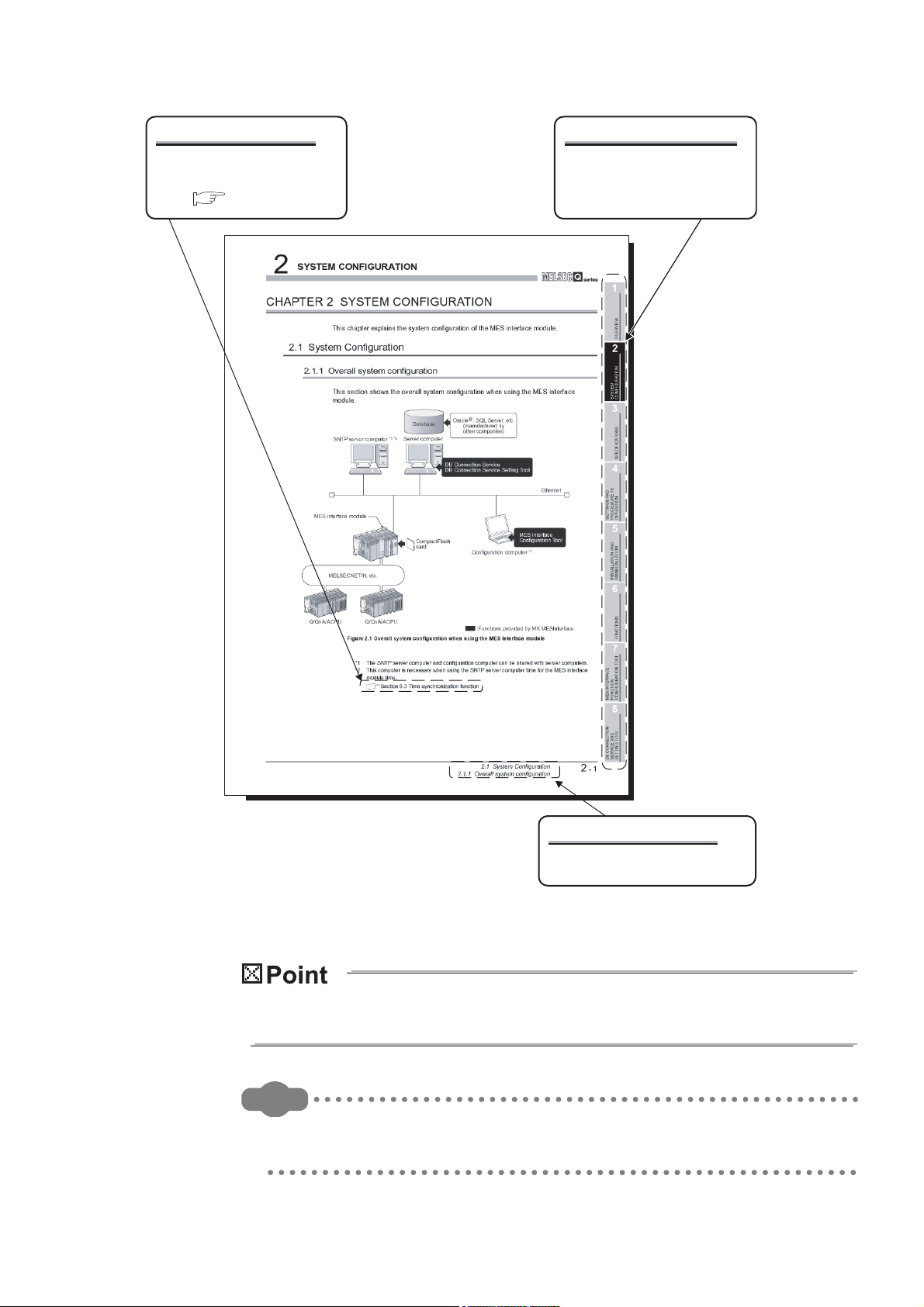
CHAPTER 2 SYSTEM CONFIGURATION 2 - 1 to 2 - 26
2.1 System Configuration ...................................................................................................................... 2 - 1
2.1.1 Overall system configuration .................................................................................................... 2 - 1
2.1.2 System configuration for installation ......................................................................................... 2 - 2
2.1.3 System configuration for initial setup ........................................................................................ 2 - 3
2.1.4 System configuration for operation ........................................................................................... 2 - 4
2.2 Applicable Systems ......................................................................................................................... 2 - 5
2.3 Connection System Equipment ....................................................................................................... 2 - 7
2.4 Operating Environment .................................................................................................................... 2 - 9
2.4.1 Configuration computer ............................................................................................................ 2 - 9
2.4.2 Server computer ..................................................................................................................... 2 - 12
2.4.3 Computer for developing XML processing applications.......................................................... 2 - 18
2.5 Checking Function Version and Serial Number ............................................................................. 2 - 19
2.6 Precautions for System Configuration ........................................................................................... 2 - 22
2.6.1 Precautions for using Redundant CPU................................................................................... 2 - 22
2.6.2 Precautions for using multiple CPU system............................................................................ 2 - 23
2.6.3 Precautions for using hubs ..................................................................................................... 2 - 23
2.6.4 Precautions for using database .............................................................................................. 2 - 24
2.6.5 Considerations for performance/specifications....................................................................... 2 - 26
2.7 Supported Software Packages ...................................................................................................... 2 - 26
A - 10
Page 13

CHAPTER 3 SPECIFICATIONS 3 - 1 to 3 - 38
3.1 Performance Specifications ............................................................................................................. 3 - 1
3.2 Accessible Devices and Ranges ..................................................................................................... 3 - 5
3.3 Function List .................................................................................................................................. 3 - 12
3.4 I/O Signals for Programmable Controller CPU .............................................................................. 3 - 16
3.4.1 I/O signal list ........................................................................................................................... 3 - 16
3.4.2 I/O signals details ................................................................................................................... 3 - 18
3.5 Buffer Memory List......................................................................................................................... 3 - 21
3.6 Buffer Memory Details ................................................................................................................... 3 - 26
3.6.1 Module status area ................................................................................................................. 3 - 26
3.6.2 Network connection status area .............................................................................................3 - 26
3.6.3 Network settings status area .................................................................................................. 3 - 27
3.6.4 Current error area ................................................................................................................... 3 - 28
3.6.5 Error log area.......................................................................................................................... 3 - 29
3.6.6 Sampling/monitoring cycle area .............................................................................................3 - 31
3.6.7 Tag status area....................................................................................................................... 3 - 31
3.6.8 Current tag data value area.................................................................................................... 3 - 33
3.6.9 Access target CPU setting status area................................................................................... 3 - 36
3.6.10 Information linkage function area ........................................................................................... 3 - 37
CHAPTER 4 SETTINGS AND PROCEDURE TO OPERATION 4 - 1 to 4 - 25
4.1 Handling Precautions....................................................................................................................... 4 - 1
4.2 Settings and Procedure to Operation .............................................................................................. 4 - 2
4.3 Parts Names .................................................................................................................................... 4 - 6
4.4 Wiring............................................................................................................................................... 4 - 8
4.4.1 Wiring ....................................................................................................................................... 4 - 8
4.4.2 Wiring precautions .................................................................................................................... 4 - 8
4.5 Intelligent Function Module Switch Settings .................................................................................... 4 - 9
4.6 Self-diagnostics Test ..................................................................................................................... 4 - 12
4.6.1 Self-loopback test ................................................................................................................... 4 - 12
4.6.2 Hardware test ......................................................................................................................... 4 - 13
4.7 CompactFlash Card....................................................................................................................... 4 - 14
4.7.1 Precautions for using a CompactFlash card........................................................................... 4 - 14
4.7.2 Installation/removing the CompactFlash card ........................................................................ 4 - 15
4.8 Battery ........................................................................................................................................... 4 - 20
4.8.1 Battery specifications.............................................................................................................. 4 - 20
4.8.2 Mounting of battery ................................................................................................................. 4 - 20
4.8.3 Battery replacement ............................................................................................................... 4 - 21
4.9 Operation without Mounting Battery ............................................................................................. 4 - 24
4.10 Removing Battery for Storage ....................................................................................................... 4 - 25
CHAPTER 5 INSTALLATION AND UNINSTALLATION 5 - 1 to 5 - 11
5.1 Installation........................................................................................................................................ 5 - 1
A - 11
Page 14

5.2 Uninstallation ................................................................................................................................... 5 - 9
CHAPTER 6 FUNCTIONS 6 - 1 to 6 - 25
6.1 DB Interface Function ...................................................................................................................... 6 - 1
6.1.1 DB interface function operation ................................................................................................ 6 - 1
6.1.2 Job execution procedure .......................................................................................................... 6 - 2
6.1.3 Tag function .............................................................................................................................. 6 - 4
6.1.4 Trigger monitoring function....................................................................................................... 6 - 5
6.1.5 Trigger buffering function.......................................................................................................... 6 - 7
6.1.6 SQL text transmission (Communication action)...................................................................... 6 - 10
6.1.7 Stored procedure call function (Communication action) ......................................................... 6 - 11
6.1.8 Arithmetic processing function (Operation action) .................................................................. 6 - 13
6.1.9 Program execution function .................................................................................................... 6 - 13
6.1.10 DB buffering function .............................................................................................................. 6 - 14
6.1.11 Precautions............................................................................................................................. 6 - 21
6.2 XML Processing Function .............................................................................................................. 6 - 23
6.3 Time Synchronization Function ..................................................................................................... 6 - 24
6.3.1 Using the SNTP time query result in the programmable controller CPU ................................ 6 - 24
6.3.2 Daylight saving time function .................................................................................................. 6 - 25
CHAPTER 7 MES INTERFACE FUNCTION CONFIGURATION TOOL 7 - 1 to 7 - 148
7.1 MES Interface Function Configuration Tool ..................................................................................... 7 - 1
7.2 Starting the MES Interface Function Configuration Tool ................................................................. 7 - 1
7.3 Screen Structure .............................................................................................................................. 7 - 2
7.3.1 Screen structure ....................................................................................................................... 7 - 2
7.3.2 Menu configuration ................................................................................................................... 7 - 4
7.3.3 Toolbar configuration................................................................................................................ 7 - 6
7.3.4 Operations using the Edit items tree......................................................................................... 7 - 7
7.4 Project File Handling........................................................................................................................ 7 - 9
7.4.1 Creating a new project.............................................................................................................. 7 - 9
7.4.2 Opening a project ..................................................................................................................... 7 - 9
7.4.3 Saving a project...................................................................................................................... 7 - 10
7.4.4 Importing a project.................................................................................................................. 7 - 11
7.4.5 Importing a CSV file................................................................................................................ 7 - 13
7.4.6 Exporting a CSV file................................................................................................................ 7 - 16
7.4.7 Printing a setting information file............................................................................................. 7 - 16
7.5 Project Setting ............................................................................................................................... 7 - 17
7.6 System Setting............................................................................................................................... 7 - 18
7.6.1 Setting items in Network setting ............................................................................................. 7 - 19
7.6.2 Setting items in Time synchronization setting......................................................................... 7 - 20
7.6.3 Setting items in Account setting.............................................................................................. 7 - 24
7.6.4 Setting items in DB buffering setting....................................................................................... 7 - 27
7.7 Access Target CPU Setting ........................................................................................................... 7 - 33
7.7.1 Setting items in Access target CPU setting ............................................................................ 7 - 34
7.8 Device Tag Setting ........................................................................................................................ 7 - 38
7.8.1 Setting items in Device Tag setting ........................................................................................7 - 39
A - 12
Page 15

7.8.2 Setting items in Array setting.................................................................................................. 7 - 43
7.8.3 Setting items in Component setting........................................................................................ 7 - 45
7.9 Server Service Setting ................................................................................................................... 7 - 53
7.9.1 Setting items in Server Service setting ................................................................................... 7 - 54
7.10 Job Setting ..................................................................................................................................... 7 - 58
7.10.1 Setting items in Job setting..................................................................................................... 7 - 59
7.10.2 Setting items in Trigger conditions ......................................................................................... 7 - 62
7.10.3 Setting items in Program execution........................................................................................7 - 75
7.10.4 Setting items in DB Buffering.................................................................................................. 7 - 79
7.10.5 Setting items for job cancellation............................................................................................ 7 - 80
7.11 Job Setting - Actions ...................................................................................................................... 7 - 81
7.11.1 Setting items in Communication action .................................................................................. 7 - 85
7.11.2 Setting items in Communication action (Select/Update/Insert/MultiSelect/Delete) ................ 7 - 92
7.11.3 Setting items in Communication action (Stored procedure) ................................................. 7 - 116
7.11.4 Setting items in Operation action.......................................................................................... 7 - 120
7.12 Online .......................................................................................................................................... 7 - 124
7.12.1 Setting the target MES interface module .............................................................................. 7 - 124
7.12.2 Writing the MES interface function settings .......................................................................... 7 - 125
7.12.3 Reading the MES interface function settings........................................................................ 7 - 127
7.12.4 Verifying the MES interface function settings ....................................................................... 7 - 127
7.12.5 Checking the working log of the MES interface module ....................................................... 7 - 128
7.12.6 Executing a job as a one-shot task....................................................................................... 7 - 135
7.13 Online - Remote operation........................................................................................................... 7 - 136
7.13.1 Checking the operation status of the MES interface function ............................................... 7 - 137
7.13.2 Manipulating the operation status of the MES interface function ......................................... 7 - 138
7.13.3 Checking the connection of the previous job execution ....................................................... 7 - 140
7.13.4 Changing the job status........................................................................................................ 7 - 141
7.13.5 Checking the operation status of DB buffering ..................................................................... 7 - 142
7.13.6 Operating the DB buffering................................................................................................... 7 - 143
7.13.7 Checking the operation status of the trigger buffering .......................................................... 7 - 144
7.13.8 Formatting the CompactFlash card ...................................................................................... 7 - 144
7.14 Help ............................................................................................................................................. 7 - 145
7.15 Precautions.................................................................................................................................. 7 - 146
CHAPTER 8 DB CONNECTION SERVICE AND SETTING TOOL 8 - 1 to 8 - 29
8.1 DB Connection Service Functions ................................................................................................... 8 - 1
8.2 Setting ODBC to the Database ........................................................................................................ 8 - 6
8.3 Starting DB Connection Service Setting Tool ................................................................................ 8 - 12
8.4 Screen Structure of DB Connection Service Setting Tool ............................................................. 8 - 13
8.4.1 Screen structure ..................................................................................................................... 8 - 13
8.4.2 Menu configuration ................................................................................................................. 8 - 14
8.5 Setting Items of DB Connection Service Setting Tool ................................................................... 8 - 15
8.6 Importing/Exporting Files .............................................................................................................. 8 - 20
8.7 Help ............................................................................................................................................... 8 - 22
8.8 Output Log Specifications .............................................................................................................. 8 - 23
A - 13
Page 16

8.8.1 Access log .............................................................................................................................. 8 - 24
8.8.2 SQL failure log ........................................................................................................................ 8 - 29
CHAPTER 9 XML MESSAGE FORMAT 9 - 1 to 9 - 6
9.1 XML Message Format Definition ..................................................................................................... 9 - 2
9.2 XML Message Format Sending Method .......................................................................................... 9 - 4
9.2.1 XML message format sending method ..................................................................................... 9 - 4
9.2.2 Sample program ....................................................................................................................... 9 - 5
CHAPTER 10 TROUBLESHOOTING 10 - 1 to 10 - 55
10.1 Error Codes ................................................................................................................................... 10 - 2
10.1.1 Finding an error code.............................................................................................................. 10 - 2
10.1.2 Error types .............................................................................................................................. 10 - 3
10.1.3 System monitor....................................................................................................................... 10 - 4
10.2 Error Code List............................................................................................................................... 10 - 7
10.2.1 Error codes for the MES interface module.............................................................................. 10 - 7
10.2.2 Error codes of DB Connection Service................................................................................. 10 - 24
10.2.3 Error codes returned in XML response messages ............................................................... 10 - 36
10.3 Troubleshooting by symptom ....................................................................................................... 10 - 37
10.3.1 When using MES Interface Function Configuration Tool...................................................... 10 - 37
10.3.2 When using DB Connection Service Setting Tool ................................................................ 10 - 44
10.3.3 When operating the MES interface module.......................................................................... 10 - 45
APPENDICES App - 1 to App - 82
Appendix 1 Functions Added in MES Interface Module and MX MESInterface .....................................App - 1
Appendix 1.1 Comparison between QJ71MES96N and QJ71MES96 ..............................................App - 1
Appendix 1.2 Addition of new functions.............................................................................................App - 4
Appendix 1.3 Operations of former versions ..................................................................................... App - 8
Appendix 2 Usable Characters and ASCII Code Tables ......................................................................App - 10
Appendix 2.1 ASCII code table........................................................................................................App - 10
Appendix 2.2 Characters that can be used for item names, component names, variable names,
etc. in the product ......................................................................................................App - 11
Appendix 2.3 Characters available for character string constants, etc............................................ App - 12
Appendix 2.4 Characters available for field names, table names,
stored procedure names,etc......................................................................................App - 12
Appendix 3 Setting Information File Format (CSV File Format) ........................................................... App - 13
Appendix 3.1 Setting information files list........................................................................................App - 13
Appendix 3.2 Setting information file format and editing precautions..............................................App - 14
Appendix 3.3 SYSTEM.CSV ...........................................................................................................App - 17
Appendix 3.4 ACCOUNT.CSV ........................................................................................................App - 19
Appendix 3.5 DST.CSV...................................................................................................................App - 21
Appendix 3.6 DBBUF.CSV ..............................................................................................................App - 23
Appendix 3.7 CPU.CSV................................................................................................................... App - 24
Appendix 3.8 TAG.CSV...................................................................................................................App - 28
Appendix 3.9 COMPONENT.CSV...................................................................................................App - 30
Appendix 3.10 SERVER.CSV ...........................................................................................................App - 32
Appendix 3.11 JOB.CSV ...................................................................................................................App - 34
A - 14
Page 17

Appendix 3.12 CONDITION.CSV......................................................................................................App - 36
Appendix 3.13 ACTION.CSV ............................................................................................................ App - 40
Appendix 3.14 ACFIELD.CSV...........................................................................................................App - 43
Appendix 3.15 ACCONDITION.CSV................................................................................................. App - 45
Appendix 3.16 ACEXCEPTION.CSV ................................................................................................ App - 47
Appendix 3.17 ACOPERATION.CSV................................................................................................App - 49
Appendix 3.18 REMOTE.CSV........................................................................................................... App - 52
Appendix 3.19 ORDERBY.CSV ........................................................................................................App - 54
Appendix 3.20 MULTISELECT.CSV ................................................................................................. App - 55
Appendix 4 Processing Time................................................................................................................ App - 57
Appendix 4.1 QJ71MES96N ...........................................................................................................App - 57
Appendix 4.2 QJ71MES96 whose first five digits of serial No. is "13092" or later .......................... App - 60
Appendix 4.3 QJ71MES96 whose first five digits of serial No. is "09102" or later and "13091" or
earlier ........................................................................................................................ App - 63
Appendix 4.4 QJ71MES96 whose first five digits of serial No. is "09101" or earlier .......................App - 66
Appendix 5 External Dimensions..........................................................................................................App - 68
Appendix 6 Data Collection Method for CPUs that cannot be Accessed Directly ................................App - 69
Appendix 7 Warning Messages in Windows(R) ................................................................................... App - 71
Appendix 7.1 Overview of warning messages ................................................................................App - 71
Appendix 7.2 Methods for disabling warning messages ................................................................. App - 72
Appendix 8 Transportation Precautions ...............................................................................................App - 80
Appendix 8.1 Controlled model .......................................................................................................App - 80
Appendix 8.2 Handling for shipping................................................................................................. App - 80
Appendix 9 Handling of Batteries and Devices with Built-in Batteries in EU Member States............... App - 81
Appendix 9.1 Disposal precautions .................................................................................................App - 81
Appendix 9.2 Exportation precautions............................................................................................. App - 82
INDEX Index - 1 to Index - 2
A - 15
Page 18

COMPLIANCE WITH EMC AND LOW VOLTAGE DIRECTIVES
(1) Method of ensuring compliance
To ensure that Mitsubishi programmable controllers maintain EMC and Low Voltage
Directives when incorporated into other machinery or equipment, certain measures
may be necessary. Please refer to one of the following manuals.
• QCPU User's Manual (Hardware Design, Maintenance and Inspection)
• Safety Guidelines
(This manual is included with the CPU module or base unit.)
The CE mark on the side of the programmable controller indicates compliance with
EMC and Low Voltage Directives.
(2) Additional measures
To ensure that this product maintains EMC and Low Voltage Directives, please refer
to one of the manuals listed under (1).
A - 16
Page 19

HOW TO USE THIS MANUAL
Section 7.6 ...... Explains a display method of the screen.
Section 7.6.1
Section 7.6.2
Section 7.6.3
Section 7.6.4
Explains setting items and
the setting methods of the screen.
* Sections 7.7 to 7.10 also provide explanations as indicated above.
This manual is organized by objective for using the MES interface module and MX
MESInterface Version 1 (SW1DNC-MESIF-E). Use this manual with referring to the
following.
(1) Features and software configuration
Section 1.1 covers the features.
Section 1.2 covers the MX MESInterface software configuration.
(2) System configuration, applicable systems, connection system equipment, and
operating environment
Section 2.1 covers the system configuration.
Section 2.2 covers the applicable systems.
Section 2.3 covers the connection system equipment.
Section 2.4 covers the operating environment.
(3) Performance specifications about the MES interface module
Section 3.1 covers the performance specifications.
Chapter 1 OVERVIEW
Chapter 2 SYSTEM CONFIGURATION
Chapter 3 SPECIFICATIONS
(4) Procedure up to MES interface module start-up
Chapter 4 SETTINGS AND PROCEDURE TO OPERATION
Section 4.2 covers the schematic procedure up to the MES interface module operation.
(5) Installation and uninstallation methods for MX MESInterface
Chapter 5 INSTALLATION AND UNINSTALLATION
CHAPTER 5 covers MX MESInterface installation and uninstallation methods.
(6) MES interface module functions
Chapter 6 FUNCTIONS
CHAPTER 6 covers the MES interface module functions.
(7) Setting method for MES Interface Function Configuration Tool
Chapter 7 MES INTERFACE FUNCTION CONFIGURATION TOOL
CHAPTER 7 covers the setting method of the MES Interface Function Configuration
Tool.
Section 7.6 to Section 7.10 provide explanations as indicated below.
A - 17
Page 20

(8) Setting method for DB Connection Service
Chapter 8 DB CONNECTION SERVICE AND SETTING TOOL
CHAPTER 8 covers the functions and setting method for the DB Connection Service.
(9) XML message format
Chapter 9 XML MESSAGE FORMAT
CHAPTER 9 covers the XML message format.
(10)Methods for checking errors and the corrective actions
Chapter 10 TROUBLESHOOTING
CHAPTER 10 covers troubleshooting and lists the error codes.
A - 18
Page 21
Remark
Displaying a chapter title
Index on the right of a page
clears the chapter of the page.
Displaying a section title
The section in which the open page
is included is clear.
Displaying a reference
Reference in this manual and
reference manual are shown
with .
The above is different from the actual page, as it is provided for explanation only.
In addition, this manual provides the following explanations.
Explains the matters to be especially noted, the functions and others related to the
description on that page.
Provides the reference destination related to the description on that page and the
convenient information.
A - 19
Page 22

GENERIC TERMS AND ABBREVIATIONS
Unless otherwise specified, this manual uses the following generic terms and
abbreviations to explain the MES interface module and MX MESInterface Version 1
(SW1DNC-MESIF-E).
Generic term/abbreviation Description
Generic term for the A1NCPU, A0J2HCPU, A1SCPU, A1SHCPU, A1SJCPU, A1SJHCPU,
ACPU
C Controller module
C24 Another term for serial communication modules
E71
Ethernet module
GX Developer
LCPU
MELSECNET/H Abbreviation for MELSECNET/H network system supporting the Q series
MELSECNET/10 Abbreviation for MELSECNET/10 network system supporting the AnU and QnA/Q4AR
MES interface module Generic term for the QJ71MES96 and QJ71MES96N MES interface module
MX MESInterface Product name for the model name SW1DNC-MESIF-E
QCPU (A mode) Generic term for the Q02CPU-A, Q02HCPU-A, and Q06HCPU-A
QCPU (Q mode)
QnACPU
Q series E71 Generic term for the QJ71E71-100, QJ71E71-B5, and QJ71E71-B2
RCPU Generic term for R04CPU, R08CPU, R16CPU, R32CPU, R120CPU
Windows Server® 2008 Windows Server® 2008 includes Windows Server® 2008 R2.
Windows Server® 2008 R2 or
later server operating system
Windows Vista® or later
Windows® 7 or later
Windows® 7 or later client
operating system
Windows® 8 or later
A2CCPU, A2CJCPU, A2NCPU, A2NCPU-S1, A2SCPU, A2SHCPU, A2ACPU, A2ACPU-S1,
A2UCPU, A2UCPU-S1, A2USCPU, A2USCPU-S1, A2USHCPU-S1, A3NCPU, A3ACPU,
A3UCPU, and A4UCPU
Generic term for the Q06CCPU-V, Q06CCPU-V-B, Q12DCCPU-V, Q24DHCCPU-V, and
Q24DHCCPU-LS
Another term for Ethernet interface modules
Generic product name for the model names of the SWnD5C-GPPW-E, SWnD5C-GPPW-EA,
SWnD5C-GPPW-EV, and SWnD5C-GPPW-EVA. (n = Version 4 or later)
- A designates a multiple-license product; -V designates a version upgraded product.
Generic term for the L02SCPU, L02SCPU-P, L02CPU, L02CPU-P, L06CPU, L06CPU-P,
L26CPU, L26CPU-P, L26CPU-BT, and L26CPU-PBT
Generic term for the Q00JCPU, Q00CPU, Q01CPU, Q02CPU, Q02HCPU, Q06HCPU,
Q12HCPU, Q25HCPU, Q02PHCPU, Q06PHCPU, Q12PHCPU, Q25PHCPU, Q12PRHCPU,
Q25PRHCPU, Q00UJCPU, Q00UCPU, Q01UCPU, Q02UCPU, Q03UDCPU, Q04UDHCPU,
Q06UDHCPU, Q10UDHCPU, Q13UDHCPU, Q20UDHCPU, Q26UDHCPU, Q03UDECPU,
Q04UDEHCPU, Q06UDEHCPU, Q10UDEHCPU, Q13UDEHCPU, Q20UDEHCPU,
Q26UDEHCPU, Q50UDEHCPU, Q100UDEHCPU, Q03UDVCPU, Q04UDVCPU,
Q06UDVCPU, Q13UDVCPU, and Q26UDVCPU
Generic term for the Q2ACPU, Q2ACPU-S1, Q2ASCPU, Q2ASCPU-S1, Q2ASHCPU,
Q2ASHCPU-S1, Q3ACPU, Q4ACPU, and Q4ARCPU
Generic term for Windows Server
®
2008 R2, Windows Server® 2012,
Windows Server® 2012 R2, and Windows Server® 2016
Generic term for Windows Vista
®
2008 R2, Windows
8, windows® 8.1, Windows Server® 2012, Windows Server® 2012 R2,
®
, Windows® 7, Windows Server® 2008, Windows Server®
Windows® 10, and Windows Server® 2016
Generic term for Windows® 7, Windows Server® 2008, Windows Server® 2008 R2,
Windows® 8, windows® 8.1, Windows Server® 2012, Windows Server® 2012 R2, Windows®
®
10, and Windows Server
Generic term for Windows
Generic term for Windows
2016
®
7, Windows® 8, windows® 8.1, and Windows® 10
®
8, Windows® 8.1, Windows Server® 2012, Windows Server®
2012 R2, Windows® 10, and Windows Server® 2016
A - 20
Page 23

DEFINITIONS AND DESCRIPTIONS OF TERMS
The following table shows the definitions and descriptions of the terms used in this
manual.
Term Description
CSV
DB buffering
HTTP
Tag for Wonderware®
Historian
MES
ODBC
SNTP
SNTP server computer
SQL
URL
URL encode
XML
Item One setting group unit included each setting type for editing
Account
Action
System switching
COMMIT Processing for finalizing the changes to a database
CompactFlash card
(CF card)
Abbreviation for Comma Separated Values
Text file in which the data are aligned and set off by commas and double quotations
Function temporarily stores SQL text that failed to be sent due to a communication error and
resends the text when the communications have been recovered
Abbreviation for Hyper Text Transfer Protocol
Protocol to exchange XML format messages between the MES interface module and user
applications in the XML processing function
Name for data unit in the data base Wonderware® Historian.
Abbreviation for Manufacturing Execution Systems
Systems for controlling and monitoring the plant status in real time to optimize production
activities
The systems enable to speed up the responses to production plan and status changes that lead
to efficient production processes and optimization of production activities.
Abbreviation for Open DataBase Connectivity
Standard specifications for software to access databases
Abbreviation for Simple Network Time Protocol
Protocol for synchronizing computer time via a TCP/IP network
Computer that provides time information to the MES interface module
This computer can be shared with a server computer.
Abbreviation for Structured Query Language
Data manipulation language and used for relational database operations
Abbreviation for Uniform Resource Locator
Notation method for indicating the locations of information resources on the Internet
Converts character strings into characters can be used in URLs.
This designates percent encoding defined by RFC3986.
Abbreviation for eXtensible Markup Language
Markup language for describing documentation, data meanings, and structures
Designates the right to use the MES interface module or server computer, or an ID necessary for
their use.
Unit for processing defined in a job
There are [Communication action] for communicating with a database and [Operation action] for
operating tag component values.
[Communication action] is a processing unit for sending one SQL text (Select, Update, Insert,
MultiSelect, or Delete) or one stored procedure execution request.
[Operation action] is a processing unit of up to 20 dyadic operations.
Function for the Redundant CPU to switch between control system and standby system of the
redundant system. (Switching from control system to standby system, and vice versa.)
Storage card regulated by the [CF+ and CompactFlash Specification] issued by the Compact
Flash Association
This memory card is necessary for the MES interface module to operate the MES interface
function.
(To the next page)
A - 21
Page 24

Term Description
Generic term for the services can be offered by a server computer to which DB Connection
Service is installed
Server service
Server computer
Job A unit of process for linking information by a MES interface module.
Stored procedure
Update settings
Configuration computer
Time zone
Tag component
(Component)
Data source
Database (DB) or
relational database
(RDB)
Ta bl e
Device
Device tag (Tag)
Trigger condition Startup conditions for job operation
There are database server service and application server service.
The database server service is a service for accessing a database.
The application server service is a service for linking with a program.
There are database server computers and application server computers.
The database server computer is a personal computer with a relational database which links
information with the MES interface module.
The application server computer is a personal computer with a program that operates upon
request from the MES interface module.
Stored procedure combines sequential processing procedures into one program against the
database, and save it to the database management system.
This executes processing based on the arguments received from MES interface module, and
returns the processing results to MES interface module.
Processing updates the MES interface module settings from MES Interface Function
Configuration Tool
Personal computer for configuring various settings required for the MES interface function in the
MES interface module
This computer can be shared with a server computer.
Standard time zone for each region of the world
Each nation uses the time difference ( 12 hours maximum) from the time at the Greenwich
Observatory in the United Kingdom (GMT) as the standard time. The region using the same time
difference is called a time zone.
The standard time for Japan is 9 hours ahead of the GMT.
In some nations, daylight time in which the clock is advanced for one hour is used in summer.
Generic term for a component (Device data) making up a device tag (Tag)
This data organizes the communications path, data type, device, etc. for access to each
programmable controller CPU device data as a single data unit.
Connection information necessary for accessing data using ODBC
®
With Windows
database can be accessed via ODBC by specifying the data source name in the MES interface
function.
Data management method that follows relational data model logic
One data is expressed as a collection of multiple items (Fields) and the data collection is
expressed as a table.
Data can be easily merged and selected using key data.
Data management format managed with relational databases
It is a two-dimensional table format composed of rows and columns.
Variety of memory data in the programmable controller
There are devices handled in units of bits and devices handled in units of words.
Data table that contains a set of information (Component) required to access the device data in
the programmable controller CPUs on the network
The MES interface module collects device data in units of tags at an interval defined in the tag.
, a data source name is assigned to connection information for management. The
(From the previous page)
A - 22
(To the next page)
Page 25

(From the previous page)
Term Description
When trigger conditions (conditions for data transmission) of multiple jobs are met in a
concentrated manner, their data and trigger times are buffered in the module's internal memory so
Trigger buffering
Data separation
Daylight saving
(Summer time)
Handshake
Field Corresponds to a column in a relational database and indicates a type of data (Record attribute).
Variable (Temporary
variable)
Record
Rollback Processing for canceling changes to a database
that actions (data operation/transmission) can be executed later using the buffered data.
Even if the frequency of data transmission triggers is high, jobs are executed without missing any
trigger.
New data and old data are mixedly exists in units of 16 bits (1 word) in 32 bits data (2 words) or
larger data due to data reception timing.
The system in which clocks are set one hour ahead of standard time in a specific period of time in
summer.
For highly reliable processing, programmable controller CPU devices are used to manage
processing between the programmable controller CPU and MES interface module.
Variable that can be used in a single job for temporary storage of values selected from a database
and for writing operation values to a database or tag components
Corresponds to a row in a relational database. One row (Record) stores the values of multiple
columns (Fields).
PACKING LIST
The following table shows the products included to the MES interface module and MX
MESInterface Version 1 (SW1DNC-MESIF-E).
Model Product name Quantity
QJ71MES96N QJ71MES96N MES interface module 1
QJ71MES96
SW1DNC-MESIF-E MX MESInterface Version 1 (with one license) (CD-ROM) (Sold Separately) 1
SW1DNC-MESIF-EA MX MESInterface Version 1 (with multiple licenses) (CD-ROM) (Sold Separately) 1
QJ71MES96 MES interface module 1
Battery (Q6BAT) 1
A - 23
Page 26
1
Computerization via
communication gateways
is unnecessary.
Information system
(Database)
<Manufacturing Execution System>
Information system
(Database)
Programmable controller CPU
(Device data)
Programmable controller CPU
(Device data)
Communication module
<Manufacturing Execution System>
<Production equipment> <Production equipment>
<Communication gateway>
Host information system
communication processing
Conventional information linkage
without the MES interface module
Controller communication
Data processing
(Operation processing,
logging, etc.)
SQL
XML
MES interface module
Information linkage using the MES interface module
OVERVIEW
CHAPTER 1 OVERVIEW
This manual explains the specifications, preparatory procedures, functions, and
troubleshooting for the MELSEC-Q series MES interface module.
When applying the following program examples to the actual system, make sure to
examine the applicability and confirm that it will not cause system control problems.
The MES interface module links the programmable controller (Production equipment)
device data with information system (Manufacturing Execution System) database without
communication gateways.
Figure 1.1 Information linkage using the MES interface module
1 - 1
Page 27
1
OVERVIEW
1.1 Features
1
This section explains the features of MX MESInterface.
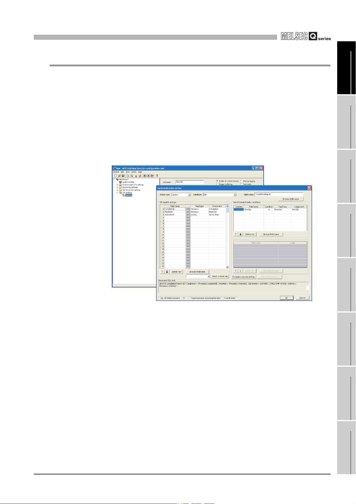
(1) Connection with the information system is enabled by simple settings without
program
Access to information system databases can be realized simply by making the
necessary settings with the setting tool.
There is no need to write programs for accessing databases, so the engineering costs
for system construction can be reduced and the work period can be shortened.
[MX MESInterface] - [MES interface function configuration tool]
OVERVIEW
2
SYSTEM
CONFIGURATION
3
SPECIFICATIONS
4
SETTINGS AND
PROCEDURE TO
OPERATION
Figure 1.2 [MX MESInterface] - [MES interface function configuration tool]
5
INSTALLATION AND
UNINSTALLATION
6
FUNCTIONS
7
MES INTERFACE
FUNCTION
CONFIGURATION TOOL
8
1.1 Features
DB CONNECTION
SERVICE AND
SETTING TOOL
1 - 2
Page 28
1
Sends data as required.
<Information system>
<Information system>
Constantly obtaining/monitoring data
from information system are required.
[In the conventional system...]
[MES interface module...]
Conditions
met
Database
Database
OVERVIEW
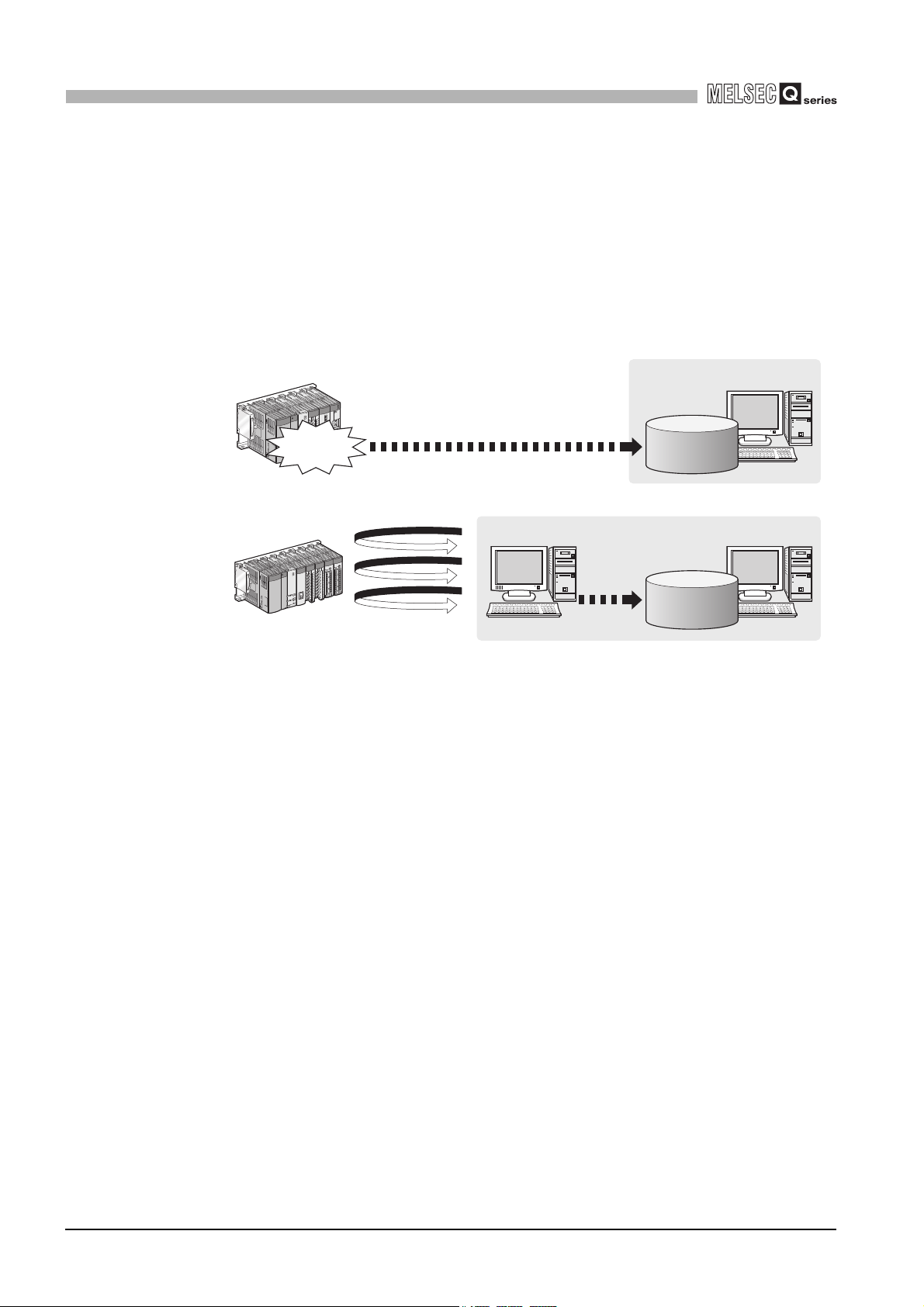
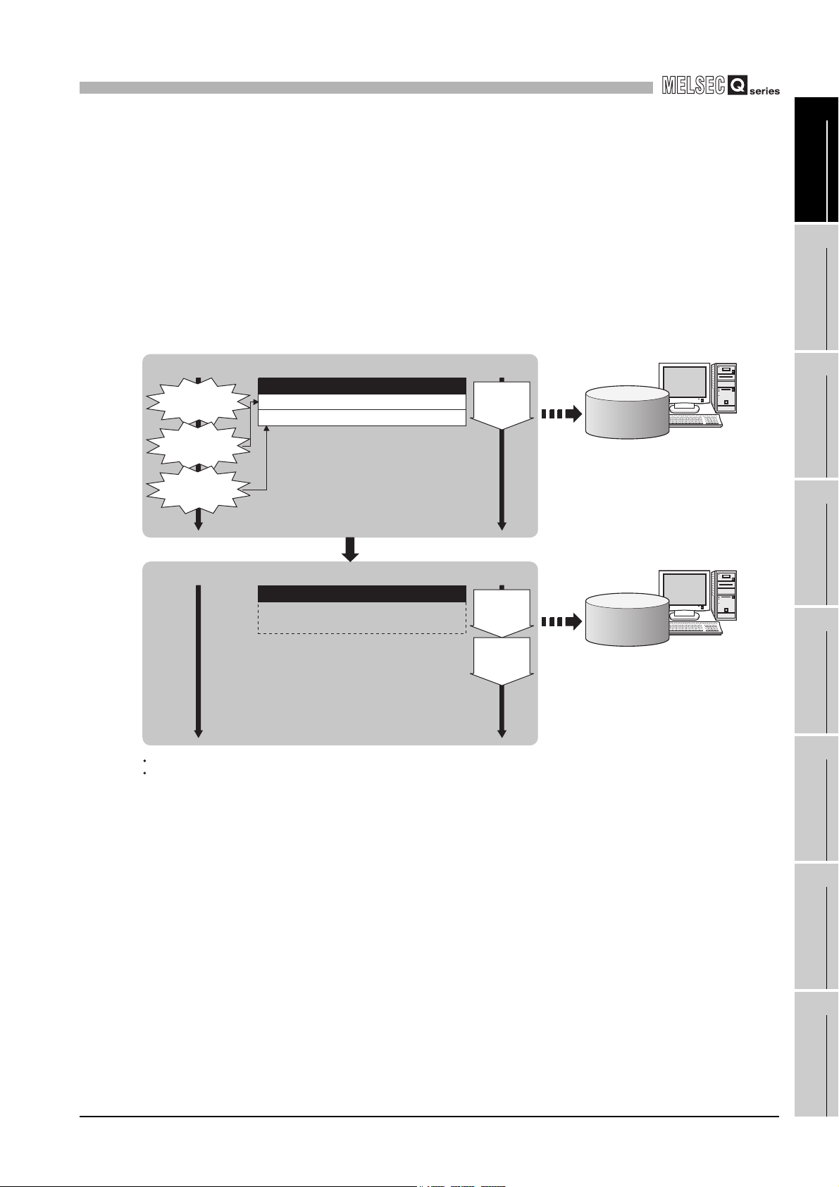
(2) The information system load can be reduced.
Data can be monitored on the MES interface module side and when the conditions
are met, the data can be sent to the information system.
Also, the data can be operated and the results of the operations can be sent to the
information system.
This can reduce the information system loads compared to the conventional system
of constantly obtaining and monitoring data.
Figure 1.3 Loads reduction of information system
1 - 3
1.1 Features
Page 29
1
[When loads are concentrated]
Trigger buffer
Job 1-1)
Trigger conditions
met
Time
Job 1-2) Trigger information (Tag data, time)
Job 3-3) Trigger information (Tag data, time)
Job 1-1)
Action
execution
Time
Sending
data
[MES interface module]
After loads have been reduced
[When loads are reduced]
Time Time
Sending
data
Trigger buffer
Job 1-2)
Action
execution
Job 3-3)
Action
execution
Job 1-2)
Trigger conditions
met
Job 3-3)
Trigger conditions
met
Database
Database
After completing the action of Job 1-1),
executes actions of Job 1-2) and 3-3)
in this order based on the trigger buffer
information.
Executes action of Job 1-1), and
stores trigger information of Job 1-2)
and 3-3) in the trigger buffer.
The numbers 1) to 3) show the order in which trigger conditions of respective jobs are met.
Job 1 and 3 are assumed to access the same database.
OVERVIEW
(3) Buffering function for reliable data acquisition/transmission
(a) Even if the frequency of data transmission triggers is high, no trigger will be
missed. (Trigger buffering function)
When multiple sets of conditions for data transmission are met in a concentrated
manner, their data and trigger times can be buffered in the module's internal
memory.
After the loads are reduced, data operations and transmission are executed using
the buffered data.
1
2
3
OVERVIEW
SYSTEM
CONFIGURATION
SPECIFICATIONS
Figure 1.4 Data buffering in the case of load concentration
4
SETTINGS AND
PROCEDURE TO
OPERATION
5
INSTALLATION AND
UNINSTALLATION
6
FUNCTIONS
7
1.1 Features
MES INTERFACE
FUNCTION
CONFIGURATION TOOL
8
DB CONNECTION
SERVICE AND
SETTING TOOL
1 - 4
Page 30
1
Database
Database
Insert...
Insert...
Update...
CompactFlash card
Insert...
Insert...
Insert...
Update...
Insert...
CompactFlash card
Disconnected
Recovered
Resend
OVERVIEW
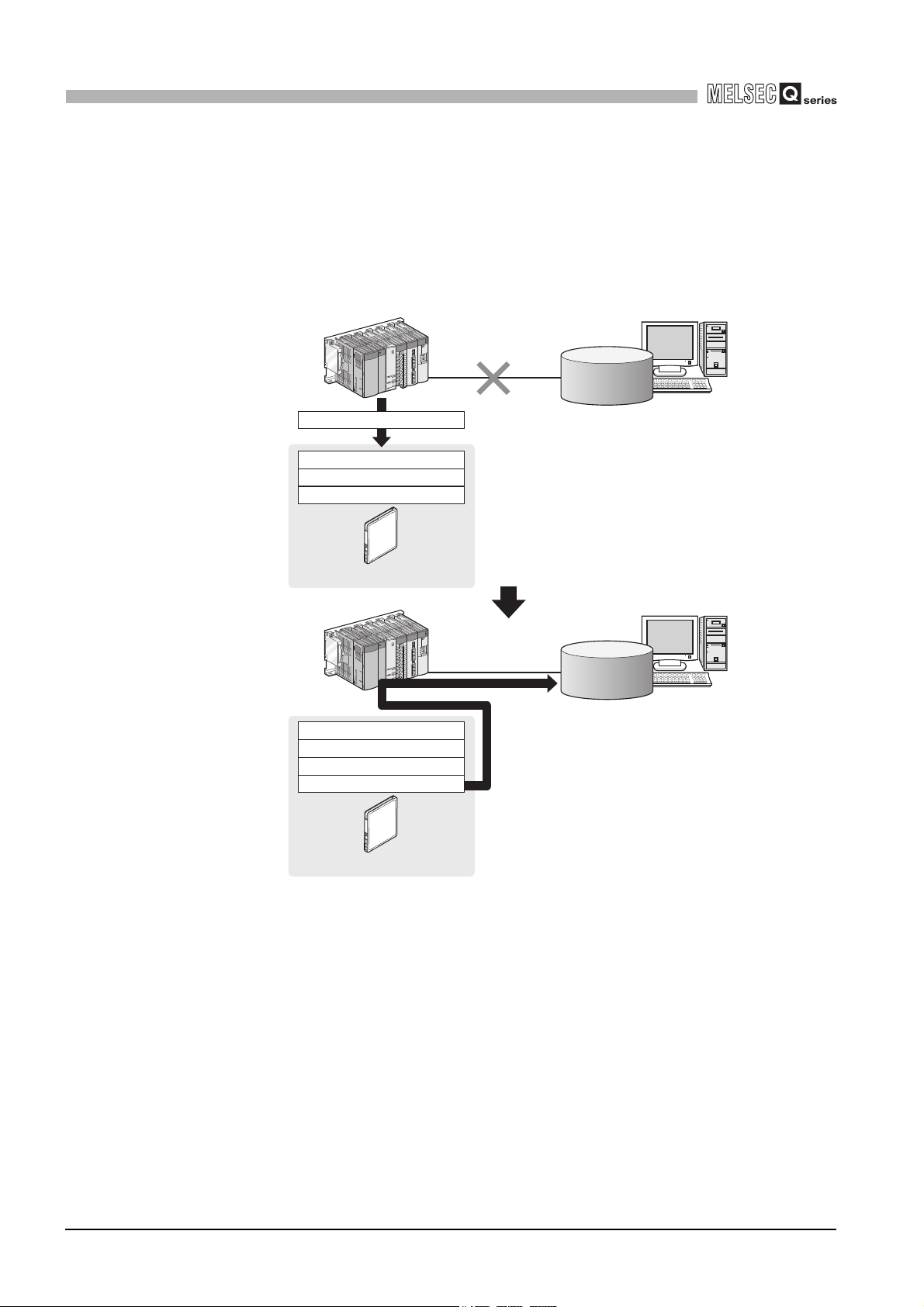
(b) Data to be send to the database are protected even if a communication error
occurs. (DB buffering function)
When an error occurs during performing communication with a database, stored
procedure execution requests or the SQL texts failed to send can be stored in a
CompactFlash card.
After the recovery, the buffered SQL texts or stored procedure execution requests
are automatically sent to the database. (Manual operation is also possible.)
Figure 1.5 Buffering of send data (SQL text) during a communication error
1 - 5
1.1 Features
Page 31

1
Database
Database
3) Sends data.
3) Sends data.
1) Instructs job execution.
<Information system>
2) Starts registered
processing.
(Job execution)
1) Instructs job execution.
<Information system>
2) Starts registered
processing.
(Job execution)
<MES interface module>
<MES interface module>
OVERVIEW
(4) Log data are available in the event of an access error
After connection with a database, when there is a communication error, a log of the
error contents can be recorded to the database side.
Analyzing the log can protect data and analyze the error.
Database
1
OVERVIEW
2
DB Connection
Service
Access
log
Figure 1.6 Obtaining logs for access errors
SQL
failure
log
(5) Directions from the information system can be realized.
Processing registered in the MES interface module can be started from information
system applications.
This enables to realize production directions from the information system.
Not only can data be sent to a database but it can also be received from a database.
This enables to download data such as production information from information
system databases.
SYSTEM
CONFIGURATION
3
SPECIFICATIONS
4
SETTINGS AND
PROCEDURE TO
OPERATION
5
INSTALLATION AND
UNINSTALLATION
Figure 1.7 Realization of directions from the information system
1.1 Features
6
FUNCTIONS
7
MES INTERFACE
FUNCTION
CONFIGURATION TOOL
8
DB CONNECTION
SERVICE AND
SETTING TOOL
1 - 6
Page 32

1
OVERVIEW
(6) Supporting diverse databases
When designing a new system, a wide range of database types can be selected.
Even when connecting to the existing system, the system can be transferred without
changing the existing database.
(7) Access independent of the database table configuration is possible.
Freely designed database tables can be used for access to databases.
When designing a new system, not only the high flexibility of design, but when
connecting to the existing system, the system can be constructed without changing
the database tables.
(8) Time synchronization using SNTP is also possible.
The clocks for the MES interface module and the programmable controller CPU can
be set through communications with an SNTP server computer.
This enables to synchronize the time for the entire system.
1 - 7
1.1 Features
Page 33

1
OVERVIEW
1.2 MX MESInterface Software Configuration
This section explains the MX MESInterface software configuration.
1
Item Description
Installer
MES Interface Function
Configuration Tool
DB Connection Service
DB Connection Service
Setting Tool
*1
Table 1.1 MX MESInterface software configuration
Installs each execution software (MES Interface Function Configuration Tool, DB
Connection Service, and DB Connection Service Setting Tool) in each operating
environment.
Operates on a configuration computer and configures various settings required for the
MES interface function.
In addition to the configuration, the application tool offers features such as the operation
status check, working log check, or stop/restart operation.
Operates on the server computer and links databases with the MES interface module
*1
and the MES Interface Function Configuration Tool.
Operates on the server computer and changes the settings of the DB Connection
Service.
*1 When the software version of MX MESInterface is "Ver.1.16S" or earlier, the Version 1 of DB
Connection Service and DB Connection Service Setting Tool are installed.
As for the MX MESInterface whose software version is "Ver.1.17T" or later, either Version 1 or
Version 2 of DB Connection Service and DB Connection Service Setting Tool are installed.
Reference
section
CHAPTER 5
CHAPTER 7
CHAPTER 8
CHAPTER 8
OVERVIEW
2
SYSTEM
CONFIGURATION
3
SPECIFICATIONS
4
SETTINGS AND
PROCEDURE TO
OPERATION
5
INSTALLATION AND
UNINSTALLATION
6
FUNCTIONS
7
MES INTERFACE
FUNCTION
CONFIGURATION TOOL
8
1.2 MX MESInterface Software Configuration
DB CONNECTION
SERVICE AND
SETTING TOOL
1 - 8
Page 34

2
Database
Oracle , SQL Server, etc.
(manufactured by
other companies)
Server computer
*3
Configuration computer
*1
Ethernet
SNTP server computer
*1 *2
MES interface module
DB Connection Service
DB Connection Service Setting Tool
CompactFlash
card
MES Interface Function
Configuration Tool
MELSECNET/H, etc.
:Functions provided by MX MESInterface
Q/L/QnA/ACPU, C Controller module
R
SYSTEM CONFIGURATION
CHAPTER 2 SYSTEM CONFIGURATION
This chapter explains the system configuration of the MES interface module.
2.1 System Configuration
2.1.1 Overall system configuration
This section shows the overall system configuration when using the MES interface
module.
2 - 1
2.1 System Configuration
2.1.1 Overall system configuration
Figure 2.1 Overall system configuration when using the MES interface module
*1 The SNTP server computer and configuration computer can be shared with server computers.
*2 This computer is necessary when using the SNTP server computer time for the MES interface
module time.
*3 The redundant server system and database cannot be used.
Section 6.3 Time Synchronization Function
Page 35

2
Installation
Commercialized product
Configuration computer
MX MESInterface
MES Interface Function
Configuration Tool
SYSTEM CONFIGURATION
1
2.1.2 System configuration for installation
This section shows system configurations for installing MX MESInterface.
(1) When installing DB Connection Service and DB Connection Service Setting
Tool on a server computer
MX MESInterface
Installation
DB Connection Service
DB Connection Service Setting Tool
Figure 2.2 Installing DB Connection Service and DB Connection Service Setting Tool
(1) When installing DB Connection Service on a database server computer, the
ODBC setting for the database used must be done beforehand.
Section 8.2 Setting ODBC to the Database
(2) When installing DB Connection Service on an application server computer, an
account for user program execution must be created beforehand.
Server computer
Commercialized product
OVERVIEW
2
SYSTEM
CONFIGURATION
3
SPECIFICATIONS
4
SETTINGS AND
PROCEDURE TO
OPERATION
(2) When installing MES Interface Function Configuration Tool on a configuration
computer
Figure 2.3 Installing MES Interface Function Configuration Tool
5
INSTALLATION AND
UNINSTALLATION
6
FUNCTIONS
7
MES INTERFACE
FUNCTION
CONFIGURATION TOOL
8
2.1 System Configuration
2.1.2 System configuration for installation
2 - 2
DB CONNECTION
SERVICE AND
SETTING TOOL
Page 36

2
Remark
r
SYSTEM CONFIGURATION
2.1.3 System configuration for initial setup
This section shows system configurations for initial setup of the MES interface module
using MES Interface Function Configuration Tool.
MES interface module
MES interface module
Figure 2.4 System configurations for initial setup of the MES interface module
Twisted pair cable
(Crossing cable)
Ethernet
or
Twisted pair cable
(Straight cable)
Ethernet
Hub
Configuration computer
Configuration compute
The following explains the network settings of the configuration computer when
connecting it to the MES interface module on a 1:1 basis.
1 Set the same network address as the one of the MES interface module in the
network settings for the configuration computer.
Default value of
"MES interface module"
IP ADDRESS
Subnet mask
Set the values to be identical.
Set different values.
Network section
192.168.3. 3
255.255.255. 0
section
Figure 2.5 Network settings for configuration computer
Host
"Configuration computer"
IP ADDRESS
Subnet mask
Network section
192.168.3.
255.255.255. 0
Host
section
1
2 Make the network settings of the configuration computer in the [Internet Protocol
(TCP/IP) Properties] dialog box.
Example: Microsoft
®
Windows® XP Professional Operating System
Figure 2.6 [Internet Protocol (TCP/IP) Properties] dialog box
3
2 - 3
2.1 System Configuration
2.1.3 System configuration for initial setup
Page 37

2
r
SYSTEM CONFIGURATION
1
2.1.4 System configuration for operation
This section shows the system configuration when operating the MES interface module.
OVERVIEW
The MES interface module can only be connected with a LAN.
The module cannot be connected via the Internet.
MES interface module
Figure 2.7 System configuration for operating the MES interface module
For the precautions when using the hubs, refer to the following section.
Section 2.6.3 Precautions for using hubs
Twisted pair cable
Ethernet
Intranet
Server computer
SNTP server computer
Configuration compute
2
SYSTEM
CONFIGURATION
3
SPECIFICATIONS
4
SETTINGS AND
PROCEDURE TO
OPERATION
5
2.1 System Configuration
2.1.4 System configuration for operation
2 - 4
INSTALLATION AND
UNINSTALLATION
6
FUNCTIONS
7
MES INTERFACE
FUNCTION
CONFIGURATION TOOL
8
DB CONNECTION
SERVICE AND
SETTING TOOL
Page 38

2
SYSTEM CONFIGURATION
2.2 Applicable Systems
Programmable
controller CPU
This section describes the applicable systems.
(1) Applicable modules and base units, and No. of modules
(a) When mounted with a CPU module
The table below shows the CPU modules and base units applicable to the MES
interface module and quantities for each CPU model.
Depending on the combination with other modules or the number of mounted
modules, power supply capacity may be insufficient.
Pay attention to the power supply capacity before mounting modules, and if the
power supply capacity is insufficient, change the combination of the modules.
Table 2.1 Applicable modules and base units, and No. of modules
Applicable module
CPU type CPU model QJ71MES96N QJ71MES96
Q00JCPU
Basic model QCPU
High Performance
model QCPU
Process CPU
Redundant CPU
Universal model
QCPU
*3
Q00CPU
Q01CPU
Q02CPU
Q02HCPU
Q06HCPU
Q12HCPU
Q25HCPU
Q02PHCPU
Q06PHCPU
Q12PHCPU
Q25PHCPU
Q12PRHCPU
Q25PRHCPU
Q00UJCPU
Q00UCPU 10012 or
Q01UCPU
Q02UCPU
Q03UDCPU
Q04UDHCPU
Q06UDHCPU
Q10UDHCPU
Q13UDHCPU
Q20UDHCPU
Q26UDHCPU
Q03UDECPU
Q04UDEHCPU
Q06UDEHCPU
Q10UDEHCPU
Q13UDEHCPU
Q20UDEHCPU
Q26UDEHCPU
Serial No. (first five digits) of
supported module
All versions All versions
All versions All versions 64
10012 or
All versions
All versions
All versions
later
All versions
09012 or
later
10012 or
later
later
09042 or
later
09042 or
later
10012 or
later
No. of modules
8
24
64
53 ×
8
24
36
64
*1
Base unit
Main base
*1
unit
:Applicable ,
(To the next page)
*2
Extension
base unit
× :N/A
2 - 5
2.2 Applicable Systems
Page 39

2
Programmable
controller CPU
C Controller module
SYSTEM CONFIGURATION
CPU type CPU model QJ71MES96N QJ71MES96
Universal model
QCPU
RCPU
Safety CPU QS001CPU - - N/A × ×
Table 2.1 Applicable modules and base units, and No. of modules (continue)
Applicable module
(From the previous page)
Q50UDEHCPU
Q100UDEHCPU
Q03UDVCPU
Q04UDVCPU
Q06UDVCPU
Q13UDVCPU
Q26UDVCPU
R04CPU
R08CPU
R16CPU
R32CPU
R120CPU
Q06CCPU-V
Q06CCPU-V-B
Q12DCCPU-V
Q24DHCCPU-V
Q24DHCCPU-LS
*5
Serial No. (first five digits) of
supported module
11052 or later
All versions
14122 or later
All versions 16072 or later 59 ×
-- N/A××
12092 or later 64
All versions
14122 or later 62
No. of modules
64
*1
Base unit
Main base
*1
unit
*2
Extension
base unit
*4
:Applicable , × :N/A
*1 Limited within the range of I/O points for the CPU module.
*2 Can be installed to any I/O slot of a base unit.
*3 Can access host station only. Cannot access other stations.
*4 RCPU can be mounted on the RQ extension base unit or Q series extension base unit which is
routed from RQ extension base unit.
*5 Use the Q12DCCPU-V whose serial No. (first five digits) is 12042 or later.
1
OVERVIEW
2
SYSTEM
CONFIGURATION
3
SPECIFICATIONS
4
SETTINGS AND
PROCEDURE TO
OPERATION
5
Use a MES interface module appropriate to each CPU module.
If an unsupported one is used for a CPU module, it does not function normally.
(b) When mounting to remote I/O station of MELSECNET/H
The MES interface module cannot be mounted to remote I/O station of the
MELSECNET/H.
Mount the MES interface module to a CPU module of the master station.
2.2 Applicable Systems
2 - 6
INSTALLATION AND
UNINSTALLATION
6
FUNCTIONS
7
MES INTERFACE
FUNCTION
CONFIGURATION TOOL
8
DB CONNECTION
SERVICE AND
SETTING TOOL
Page 40

2
SYSTEM CONFIGURATION
(2) Application to multiple CPU system
When using the MES interface module in multiple CPU system, refer to the following
manual.
QCPU User's Manual (Multiple CPU System)
The MES interface module is compatible with the multiple CPU system with function
version B from the first product.
2.3 Connection System Equipment
This section explains the equipment can be connected to the MES interface module.
(1) CompactFlash card (sold separately)
The MES interface module requires one CompactFlash® card.
Use a CompactFlash card manufactured by Mitsubishi listed in the following table.
Failure to do so may cause a problem such as data corruption in the CompactFlash
card and system stop.
Table 2.2 CompactFlash card (sold separately)
Model Description
GT05-MEM-128MC CompactFlash card 128 MB
GT05-MEM-256MC CompactFlash card 256 MB
QD81MEM-512MBC CompactFlash card 512MB
QD81MEM-1GBC CompactFlash card 1GB
(1) For CompactFlash card format, use the formatting function of MES Interface
Function Configuration Tool.
Section 7.13.8 Formatting the CompactFlash card
(2) A CompactFlash card has a service life (restriction on the number of writes).
For details, refer to the specifications of each product.
2 - 7
2.3 Connection System Equipment
Page 41

2
SYSTEM CONFIGURATION
1
(2) Twisted pair cable (sold separately)
Use twisted pair cable that meets IEEE 802.3 10BASE-T/100BASE-TX standards.
(a) For 100 Mbps
Either 1) or 2) of the following can be used.
1) Unshielded twisted pair (UTP) cable
Straight cable: Category 5 or higher
Crossing cable: Category 5 or 5e
2) Shielded twisted pair (STP) cable
Straight cable: Category 5 or higher
Crossing cable: Category 5 or 5e
(b) For 10 Mbps
Either 1) or 2) of the following can be used.
1) Unshielded twisted pair (UTP) cable
Straight cable: Category 3 or higher
Crossing cable: Category 3 to 5e
2) Shielded twisted pair (STP) cable
Straight cable: Category 3 or higher
Crossing cable: Category 3 or 5e
During high speed communication (100 Mbps) via 100BASE-TX connection,
communication errors may occur due to the effect of high frequency noise
generated from the equipment other than programmable controller, depending on
the installation environment.
Take the following countermeasures on the MES interface module side to
eliminate the effect of high frequency noise when constructing the network
system.
(1) Wiring
• Do not install the twisted pair cables together with the main circuit or
power lines, or bring them close to each other.
• Make sure to place the twisted pair cable in a duct.
(2) Cable
• In the environment where the cable is susceptible to noise, use the
shielded twisted pair cable (STP cable).
(3) 10 Mbps communication
• Connect the 10 Mbps-compatible equipment with the MES interface
module and transmit the data to the equipment at a transmission speed of
10 Mbps.
OVERVIEW
2
SYSTEM
CONFIGURATION
3
SPECIFICATIONS
4
SETTINGS AND
PROCEDURE TO
OPERATION
5
INSTALLATION AND
UNINSTALLATION
6
FUNCTIONS
7
2.3 Connection System Equipment
MES INTERFACE
FUNCTION
CONFIGURATION TOOL
8
DB CONNECTION
SERVICE AND
SETTING TOOL
2 - 8
Page 42

2
SYSTEM CONFIGURATION
2.4 Operating Environment
2.4.1 Configuration computer
This section explains the operating environment for the configuration computer.
Table 2.3 Operating environment for configuration computer
Item Description
Computer
CPU
Required
memory
Hard disk available capacity 64 MB or more
Disc drive CD-ROM disc drive
Display Resolution 1024 × 768 pixels or higher
Operating system
(English version)
Interface Ethernet (IPv4)
Microsoft
See Table 2.4 "Performance required for personal computer and operating systems".
Windows
Windows
Windows
Windows
Windows Vista
Windows Server
Windows
Windows
Windows
®
Windows® supported personal computer.
®
10 (Home, Pro, Enterprise, Education)
®
8.1, Windows® 8.1 (Pro, Enterprise)
®
8, Windows® 8 (Pro, Enterprise)
®
7 (Starter, Home Premium, Professional, Ultimate, Enterprise)
®
(Home Basic, Home Premium, Business, Ultimate, Enterprise)
®
2003
®
2000 Server Operating System Service Pack 2 or later
®
XP (Professional, Home)
®
2000 Professional Operating System Service Pack 2 or later
2 - 9
2.4 Operating Environment
2.4.1 Configuration computer
Page 43

2
SYSTEM CONFIGURATION
1
(1) Instructions for operating system
(a) Performance required for personal computer and operating systems
Table 2.4 Performance required for personal computer and operating systems
Operating system
Windows® 10
Windows® 8.1
Windows® 8
Windows® 7
Windows Vista
Windows Server® 2003
Windows® 2000 Server
Windows® XP
Windows® 2000 Professional
®
Performance required for personal computer
CPU Required memory
®
CoreTM2 Duo 2GHz or more
Intel
Pentium
Pentium
Pentium
®
1GHz or more
®
550MHz or more
®
300MHz or more
32-bit version: 1GB or more
64-bit version: 2GB or more
1GB or more
256 MB or more
128 MB or more
(b) Supported version
Table 2.5 Supported version of MX MESInterface
Operating system
Windows® 2000 Professional
Windows® XP(32-bit version)
Windows® 2000 Server
Windows Server® 2003(32-bit version)
Windows Vista®(32-bit version)
Windows® 7(32-bit version)
Windows® 7(64-bit version)
Windows® 8(32-bit version, 64-bit version)
Windows® 8.1(32-bit version, 64-bit version)
Windows® 10(32-bit version, 64-bit version)
Supported version of MX
MESInterface
All versions
Version 1.04E or later
Version 1.06G or later
Version 1.08J or later
Version 1.10L or later
Version 1.12N or later
Version 1.16S or later
(c) User authority
Log on as a user having administrator authority.
• Installation, uninstallation are available only by the administrator's authority.
• Use the product as a user having a privilege higher than 'Standard user' or
'Administrator'.
OVERVIEW
2
SYSTEM
CONFIGURATION
3
SPECIFICATIONS
4
SETTINGS AND
PROCEDURE TO
OPERATION
5
INSTALLATION AND
UNINSTALLATION
6
FUNCTIONS
(d) The functions cannot be used
This product may not perform properly, when these functions are used.
• Activating the application with Windows
®
compatible mode
• Simplified user switch-over
• Remote desktop
• Power save mode (Standby, Hibernate, Sleep)
• Windows XP Mode
• Windows Touch or Touch
• Modern UI
• Client Hyper-V
• Tablet mode
• Virtual Desktops
2.4 Operating Environment
2.4.1 Configuration computer
2 - 10
7
MES INTERFACE
FUNCTION
CONFIGURATION TOOL
8
DB CONNECTION
SERVICE AND
SETTING TOOL
Page 44

2
SYSTEM CONFIGURATION
(e) The setting cannot be used
In the following case, the screen of this product may not work properly.
• The size of the text and/or other items on the screen are changed to values
other than default values (such as 96DPI, 100%, and 9 pt).
• The resolution of the screen is changed in operation.
• The multi-display is set.
(f) Others
• If the Windows firewall setting is enabled, functions may not operate correctly.
Section 5.1 Installation
2 - 11
2.4 Operating Environment
2.4.1 Configuration computer
Page 45

2
SYSTEM CONFIGURATION
1
2.4.2 Server computer
This section explains the operating environment for the server computer.
Table 2.6 Operating environment for server computer
Item Description
Computer
CPU
Required
memory
Hard disk available capacity 64 MB or more
Disc drive CD-ROM disc drive
Display Resolution 1024 × 768 pixels or higher
When using DB
Connection
Service and DB
Connection
Service Setting
Tool Version 2
Operating system
(English version)
When using DB
Connection
Service and DB
Connection
Service Setting
Tool Version 1
Interface Ethernet(IPv4)
When using DB
Connection
Required software
Service and DB
Connection
Service Setting
Tool Version 2
Microsoft
See Table 2.7 "Performance required for personal computer and operating systems".
Only 64-bit version operating system is supported by Version 2.
Windows Server
Windows
Windows
Windows Server
Windows
Windows Server
Windows
Windows Server
Windows
Windows
Windows Server
Windows
Windows Server
Windows
Windows Server
Windows Server
Windows Vista
Windows Server
Windows Server
Windows
Windows XP
Windows
When using the DB interface function: relational database (English version)
®
Windows® supported personal computer.
®
2016 (Standard)
®
10 (Pro, Enterprise)
®
8.1 (Pro, Enterprise)
®
2012 R2 (Standard)
®
8 (Pro, Enterprise)
®
2012 (Standard)
®
7 (Professional, Ultimate, Enterprise)
®
2008 R2 (Standard)
®
10 (Pro, Enterprise)
®
8.1 (Pro, Enterprise)
®
2012 R2
®
8 (Pro, Enterprise)
®
2012
®
7 (Professional, Ultimate, Enterprise)
®
2008 R2
®
2008
®
(Business, Ultimate, Enterprise)
®
2003 x64 Edition
®
2003
®
2000 Server Service Pack 2 or later
®
Professional (32bit)
®
2000 Professional Service Pack 2 or later
®
•Oracle
•Oracle
•Microsoft
•Microsoft
•Microsoft
•Microsoft
•Microsoft
•Microsoft® Access® 2016 (32bit)
•Microsoft® Access® 2013 (32bit)
•Microsoft® Access® 2010 (32bit)
12c (Express, Standard, Enterprise) (64bit)
®
11g (Standard, Enterprise) (64bit)
®
SQL Server® 2017 (Express, Standard, Enterprise) (64bit)
®
SQL Server® 2016 (Express, Standard, Enterprise) (64bit)
®
SQL Server® 2014 (Express, Standard, Enterprise) (64bit)
®
SQL Server® 2012 (Express, Standard, Enterprise) (64bit)
®
SQL Server® 2008 R2 (Express, Standard, Enterprise) (64bit)
*2
*2
*2
OVERVIEW
2
SYSTEM
CONFIGURATION
3
SPECIFICATIONS
4
SETTINGS AND
PROCEDURE TO
OPERATION
5
INSTALLATION AND
UNINSTALLATION
6
FUNCTIONS
7
MES INTERFACE
FUNCTION
*1
CONFIGURATION TOOL
8
2.4 Operating Environment
2.4.2 Server computer
2 - 12
DB CONNECTION
SERVICE AND
SETTING TOOL
Page 46

2
SYSTEM CONFIGURATION
Required software
Item Description
When using the DB interface function: relational database (English version)
When using DB
Connection
Service and DB
Connection
Service Setting
Tool Version 1
When using the time synchronization function: SNTP server
(Equipped as a standard to Windows
Server
*1 Itanium processor (IA-64) is not supported.
*2 Only 32-bit version of DB Connection Service and DB Connection Service Setting Tool Version 2 is
supported.
®
•Oracle
•Oracle
•Oracle
•Oracle
•Oracle
•Microsoft
•Microsoft
•Microsoft
•Microsoft® SQL Server® 2008 (32bit, 64bit)
•Microsoft® SQL Server® 2005 (32bit)
•Microsoft
•Microsoft
•Microsoft
•Microsoft
•Microsoft
•Microsoft
•Microsoft
• Wonderware
12c (64bit)
®
11g (32bit, 64bit)
®
10g (32bit)
®
9i (32bit)
®
8i (32bit)
®
SQL Server® 2014 (32bit, 64bit)
®
SQL Server® 2012 (32bit, 64bit)
®
SQL Server® 2008 R2 (32bit, 64bit)
®
SQL Server® 2000 (32bit)
®
SQL Server® 2000 Desktop Engine (MSDE 2000)
®
Access® 2013 (32bit)
®
Access® 2010 (32bit)
®
Access® 2007
®
Access® 2003
®
Access® 2000
®
Historian 9.0 (Industrial SQL Server®)
®
®
2008, Windows Server® 2012, and Windows Server® 2016)
2000 Server, Windows Server® 2003, Windows
*1
*1
2 - 13
2.4 Operating Environment
2.4.2 Server computer
Page 47

2
SYSTEM CONFIGURATION
1
(1) Instructions for operating system
(a) Performance required for personal computer and operating systems
Table 2.7 Performance required for personal computer and operating systems
Operating system
Windows Server® 2016
Windows® 10 (Pro, Enterprise)
Windows® 8.1 (Pro, Enterprise)
Windows Server® 2012 R2
Windows® 8 (Pro, Enterprise)
Windows Server® 2012
Windows® 7
(Professional, Ultimate, Enterprise)
Windows Server® 2008 R2
Windows Server® 2008
Windows Vista
(Business, Ultimate, Enterprise)
Windows Server® 2003
Windows® 2000 Server
Windows® XP Professional
Windows® 2000 Professional
*1
*2
*2
*2
*2
*2
*2
*3
®
*3
*3
*3
*3
*3
OVERVIEW
Performance required for personal computer
CPU Required memory
2GB or more
32-bit version: 1GB or more
64-bit version: 2GB or more
Intel® CoreTM2 Duo 2GHz or more
When using DB Connection Service and DB
Connection Service Setting Tool Version 2:
®
Intel
CoreTM2 Duo 2GHz or more
*2
When using DB Connection Service and DB
Connection Service Setting Tool Version 1:
®
Pentium
Pentium® 2GHz or more
Pentium® 1GHz or more
Pentium® 550MHz or more
1GHz or more
2GB or more
32-bit version: 1GB or more
64-bit version: 2GB or more
2GB or more
32-bit version: 1GB or more
64-bit version: 2GB or more
2GB or more
1GB or more
256 MB or more
2
SYSTEM
CONFIGURATION
3
SPECIFICATIONS
4
SETTINGS AND
PROCEDURE TO
OPERATION
5
Pentium® 300MHz or more
128 MB or more
*1 Only DB Connection Service and DB Connection Service Setting Tool Version 2 can be used.
The supported operating system is 64-bit version only.
*2 Only 64-bit version operating system is supported when using DB Connection Service and DB
Connection Service Setting Tool Version 2.
*3 Only DB Connection Service and DB Connection Service Setting Tool Version 1 can be used.
INSTALLATION AND
UNINSTALLATION
6
FUNCTIONS
7
MES INTERFACE
FUNCTION
CONFIGURATION TOOL
8
2.4 Operating Environment
2.4.2 Server computer
2 - 14
DB CONNECTION
SERVICE AND
SETTING TOOL
Page 48

2
SYSTEM CONFIGURATION
(b) Supported version
Table 2.8 Supported version of MX MESInterface
Windows® 2000 Professional
Windows® XP(32-bit version)
Windows® 2000 Server
Windows Server® 2003(32-bit version)
Windows Server® 2003(64-bit version*1)
Windows Server® 2008(32-bit version, 64-bit version*1)
Windows Vista®(32-bit version)
Windows Vista®(64-bit version)
Windows® 7(32-bit version, 64-bit version)
Windows® 8(32-bit version, 64-bit version)
Windows Server® 2012
Windows® 8.1(32-bit version, 64-bit version)
Windows® 10(32-bit version, 64-bit version)
Windows Server® 2016
*1 Itanium processor(IA-64) is not supported.
Operating system
Supported version of
MX MESInterface
All versions
Version 1.05F or later
Version 1.04E or later
Version 1.05F or later
Version 1.06G or later
Version 1.10L or later
Version 1.12N or later
Version 1.16S or later
Version 1.17T or later
(c) User authority
• Installation, uninstallation are available only by the administrator's authority.
• MX MESInterface is available only by the administrator's authority.
(d) The functions cannot be used
This product may not perform properly, when these functions are used.
®
• Activating the application with Windows
compatible mode
• Simplified user switch-over
• Remote desktop
• Power save mode (Standby, Hibernate, Sleep)
• Windows XP Mode
• Windows Touch or Touch
• Modern UI
• Client Hyper-V
• Server Core Installation
• Tablet mode
• Virtual Desktops
(e) The setting cannot be used
In the following case, the screen of this product may not work properly.
• The size of the text and/or other items on the screen are changed to values
other than default values (such as 96DPI, 100%, and 9 pt).
• The resolution of the screen is changed in operation.
• The multi-display is set.
2 - 15
(f) Others
• If the Windows firewall setting is enabled, functions may not operate correctly.
Section 5.1 Installation
2.4 Operating Environment
2.4.2 Server computer
Page 49

2
SYSTEM CONFIGURATION
(2) Considerations for the database
The restrictions when using database are as follows:
• To use a relational database, a license based on the number of MES interfaces is
usually required. (Varies depending on the relational database type and license
type.)
For details, please consult the relational database vendor.
• The redundant relational data base cannot be used.
• For the operating environment, refer to the specifications of the relational
database used. Use 32-bit operating system for 32-bit relational database.
• For the precautions for using each database, refer to the following section.
Section 2.6.4 Precautions for using database
(a) Supported version
Table 2.9 Supported version of Databases
Database
Oracle® 8i
Oracle® 9i
Oracle® 10g
Oracle® 11g
Oracle® 12c
Microsoft® SQL Server® 2000
Microsoft® SQL Server® 2005
Microsoft® SQL Server® 2008
Microsoft® SQL Server® 2008 R2
Microsoft® SQL Server® 2012
Microsoft® SQL Server® 2014
Microsoft® SQL Server® 2016
Microsoft® SQL Server® 2017
Microsoft® SQL Server® 2000 Desktop Engine
(MSDE 2000)
Microsoft® Access® 2000
Microsoft® Access® 2003
Microsoft® Access® 2007
Microsoft® Access® 2010
Microsoft® Access® 2013
Microsoft® Access® 2016
Wonderware® Historian 9.0®(Industrial SQL Server®)
Serial No. (first five digits) of
MES interface module
All versions All versions
12012 or later Version 1.05F or later
16072 or later Version 1.12N or later
All versions All versions
09012 or later Version 1.01B or later
12012 or later Version 1.05F or later
12092 or later Version 1.06G or later
14122 or later Version 1.09K or later
17122 or later Version 1.14Q or later
17122 or later Version 1.17T or later
17122 or later Version 1.19V or later
All versions All versions
10012 or later Version 1.04E or later
13092 or later Version 1.08J or later
15102 or later Version 1.10L or later
17122 or later Version 1.17T or later
09012 or later Version 1.01B or later
Supported version of
MX MESInterface
1
OVERVIEW
2
SYSTEM
CONFIGURATION
3
SPECIFICATIONS
4
SETTINGS AND
PROCEDURE TO
OPERATION
5
INSTALLATION AND
UNINSTALLATION
6
FUNCTIONS
7
2.4 Operating Environment
2.4.2 Server computer
2 - 16
MES INTERFACE
FUNCTION
CONFIGURATION TOOL
8
DB CONNECTION
SERVICE AND
SETTING TOOL
Page 50

2
Data bases
(32bit)
Data bases
(64bit)
SYSTEM CONFIGURATION
(3) Considerations for the database
The combinations of databases, operating systems, and DB Connection Service and
DB Connection Service Setting Tool supported by Q series MES interface modules
are as follows.
Table 2.10 Supported versions of databases/operating systems for each version of DB Connection Service
and DB Connection Service Setting Tool
Database
Oracle
SQL Server ×
Access
Oracle
SQL Server
Access × × ×
OS (32bit) OS (64bit) OS (32bit) OS (64bit) OS (64bit)
*1 When using DB Connection Service and DB Connection Service Setting Tool Version 2, use a
MES interface module with a serial number whose first 5 digits are "17122" or later.
Version 1
××
--
Version2 (32bit)
○: Supported, ×: Unsupported, -: No combination
*1
×
Version2 (64bit)
*1
×
2 - 17
2.4 Operating Environment
2.4.2 Server computer
Page 51

2
SYSTEM CONFIGURATION
2.4.3 Computer for developing XML processing applications
This section explains the operating environment of the computer for developing XML
processing applications.
Table 2.11 Operating environment of computer for developing XML processing applications
Item Description
Program development environment
®
Microsoft
Sun Microsystems J2SE v1.4.2
Visual Studio® .NET 2003
1
2
3
OVERVIEW
SYSTEM
CONFIGURATION
SPECIFICATIONS
4
SETTINGS AND
PROCEDURE TO
OPERATION
5
INSTALLATION AND
UNINSTALLATION
6
FUNCTIONS
7
2.4 Operating Environment
2.4.3 Computer for developing XML processing applications
2 - 18
MES INTERFACE
FUNCTION
CONFIGURATION TOOL
8
DB CONNECTION
SERVICE AND
SETTING TOOL
Page 52

2
12012
MAC ADD.
Serial No. (first 5 digits)
Relevant regulation standards
SYSTEM CONFIGURATION
2.5 Checking Function Version and Serial Number
The serial No. and function version of the MES interface module can be confirmed on the
rating plate and GX Developer's system monitor.
(1) Confirming the serial number on the rating plate
The rating plate is situated on the side face of the MES interface module.
Figure 2.8 "SERIAL" on the rating plate on the side of the MES interface module
2 - 19
2.5 Checking Function Version and Serial Number
Page 53

2
191021102450001-B
Function version
Serial number
SYSTEM CONFIGURATION
(2) Checking on the front of the module
The serial No. and function version on the serial number display are also indicated on
the front of the module (lower part).
1
2
3
OVERVIEW
SYSTEM
CONFIGURATION
SPECIFICATIONS
Figure 2.9 "SERIAL" on the serial number display on the front of the MES interface module
4
SETTINGS AND
PROCEDURE TO
OPERATION
5
INSTALLATION AND
UNINSTALLATION
6
FUNCTIONS
7
2.5 Checking Function Version and Serial Number
MES INTERFACE
FUNCTION
CONFIGURATION TOOL
8
DB CONNECTION
SERVICE AND
SETTING TOOL
2 - 20
Page 54

2
Serial
number
Function
version
SYSTEM CONFIGURATION
(3) Confirming the serial number on the system monitor (Product Information List)
To display the screen for checking the serial number and function version, select
[Diagnostics] [System monitor] in GX Developer.
Figure 2.10 [Product Information List] of GX Developer
1 Production number display
2 Since the MES interface module does not support the production number display,
"-" is displayed.
Product inf. list
The serial No. on the rated plate and on the front of the module may not match the
serial No. displayed in the product information list of GX Developer.
• The serial No. on the rated plate and on the front of the module indicates
the management information of the product.
• The serial No. displayed in the product information list of GX Developer
indicates the functional information of the product.
The functional information of the product is updated when some functions
are added.
2 - 21
2.5 Checking Function Version and Serial Number
Page 55

2
REMARKS
SYSTEM CONFIGURATION
2.6 Precautions for System Configuration
This section describes precautions for system configuration.
1
2.6.1 Precautions for using Redundant CPU
The following describes the precautions for using the Redundant CPU.
(1) Mountable base unit
When using the MES interface module in a redundant system, be sure to mount the
MES interface module to the extension base unit for CPU or redundant power supply.
The MES interface module cannot be mounted to the main base unit in a redundant
system.
(2) [Access target CPU setting]
• When the MES interface module is mounted to the Redundant CPU, it can
access the CPU of host station only.
It cannot access the CPU of other station.
• When the MES interface module is mounted to other than the Redundant CPU, it
cannot access the Redundant CPU of other station.
(3) [Device Tag setting]
• When a system switching occurs to the Redundant CPU, collection of device tag
may stop for about 15 seconds.
• When selecting [High-speed sampling] from Sampling settings of Device Tag
setting, be sure to create system area for the user setting to the Redundant CPU
of both systems in the same capacity.
Section 7.8.1 (1) Creating a user-specified system area
OVERVIEW
2
SYSTEM
CONFIGURATION
3
SPECIFICATIONS
4
SETTINGS AND
PROCEDURE TO
OPERATION
5
(4) [Job setting]
When accessing the Redundant CPU, it is recommended to select [Handshake
operation] for the trigger condition of a job.
When other than [Handshake operation] is selected for the trigger condition, the
following phenomenon may occur at system switching of a redundant system.
• Data separation
• The write data is not reflected to the programmable controller CPU.
Section 7.10.2 (8) Handshake operation
2.6 Precautions for System Configuration
2.6.1 Precautions for using Redundant CPU
2 - 22
INSTALLATION AND
UNINSTALLATION
6
FUNCTIONS
7
MES INTERFACE
FUNCTION
CONFIGURATION TOOL
8
DB CONNECTION
SERVICE AND
SETTING TOOL
Page 56

2
SYSTEM CONFIGURATION
2.6.2 Precautions for using multiple CPU system
The following describes the precautions for using the multiple CPU system.
(1) Access to each CPU module at start-up of multiple CPU system
In the system in which a MES interface module is mounted in the multiple CPU
system, an error may occur when accessing other CPU from the MES interface
module or accessing the other station via a network module controlled by other CPU
from the MES interface module due to the difference of start-up time of each CPU
module. In this case, clear the error in the MES interface module after starting up
other CPU.
Page 10-3, Section 10.1.2 (2)
The start-up of other CPUs can be checked with the special relays, SM220 to SM223.
User's manual for the CPU module used
2.6.3 Precautions for using hubs
The following describes the precautions for using the hub.
(1) IEEE802.3x flow control in full-duplex communication
The MES interface module does not support the IEEE802.3x flow control.
Therefore, when the load of an Ethernet line is high in the connection with the hub
supporting IEEE802.3x, the data to be sent to the module may be lost.
If the above mentioned phenomenon occurs, add the hubs and reduce the load on the
Ethernet line applied on single hub.
2 - 23
2.6 Precautions for System Configuration
2.6.2 Precautions for using multiple CPU system
Page 57

2
SYSTEM CONFIGURATION
1
2.6.4 Precautions for using database
The following shows the precautions for using database.
OVERVIEW
For characters that can be used for field and table names, refer to the following:
Appendix 2.4 Characters available for field names, table names, stored
procedure names,etc.
(1) Microsoft® SQL Server®
(a) Set "SQL Server and Windows" or "SQL Server and Windows Authentication
mode" for the security authentication mode.
®
•Microsoft
Configure the setting in [SQL Server Properties (Configure)].
SQL Server® 2000
2
SYSTEM
CONFIGURATION
3
SPECIFICATIONS
4
SETTINGS AND
PROCEDURE TO
OPERATION
5
Figure 2.11 [SQL Server Properties (Configure)]
®
•Microsoft
Set the security authentication mode into the Mixed Mode.
Specify the command parameter at installation of the MSDE 2000.
setup sapwd="sa" SECURITYMODE=SQL
(sa: Specify any password)
(b) For Microsoft
arguments, and input/output arguments of a stored procedure which returns a
result set cannot be acquired.
SQL Server® 2000 Desktop Engine (MSDE 2000)
®
SQL Server® 2008/2012/2014/2016/2017 return values, output
2.6 Precautions for System Configuration
2.6.4 Precautions for using database
2 - 24
INSTALLATION AND
UNINSTALLATION
6
FUNCTIONS
7
MES INTERFACE
FUNCTION
CONFIGURATION TOOL
8
DB CONNECTION
SERVICE AND
SETTING TOOL
Page 58

2
SYSTEM CONFIGURATION
(c) When MX MESInterface whose software version is "1.16S" or earlier is installed,
use SQL Server with any of the following condition:
• The owner of the database file created with SQL Server is an SQL Server
authenticated user.
• The server administrator authentication (sysadmin) is not added to the server
role of the user whose field information is to be referenced.
However, this restriction is not applicable when MX MESInterface whose software
version is "1.17T" or later is installed.
(2) Microsoft® Access
(a) Using in the following environments is not recommended.
• Where under overload
• Where high reliability, such as non-stop operation for 24 hours, is required
For details, refer to the website of Microsoft.
blogs.technet.microsoft.com/officesupportjp/2017/02/08/ace_memory
(b) The number of fields to be updated (UPDATE) by the one [Communication action]
is up to 127.
(c) Do not make multiple accesses to one and the same file.
(Do not make access from multiple MES interface modules.)
(d) There are some restrictions for the data type which can be assigned to tag
component, constant value, and variable with MES Interface Function
Configuration Tool.
Section 7.11.1 (1) About tag components
Section 7.11.1 (2) About constants
Section 7.11.1 (3) About variables
(3) Wonderware® Historian
®
2 - 25
(a) The insertion (INSERT) only can be used with [Communication action].
(b) The rollback of insertion (INSERT) to the database is disabled.
2.6 Precautions for System Configuration
2.6.4 Precautions for using database
Page 59

2
SYSTEM CONFIGURATION
2.6.5 Considerations for performance/specifications
(1) Startup time
The time from when a CPU module is started to when the processing of MES
interface function is ready for execution in an MES interface module varies depending
on the system configuration and settings.
The startup time can be lengthened depending on any of the following factors:
• Operating environment (network and the CompactFlash card)
• Settings of the MES interface module
• Number of DB bufferings
• Model name of the MES interface module (QJ71MES96N, QJ71MES96)
When using 'Value monitoring startup' or 'Handshake operation' for a trigger condition,
check that 'Information linkage status (X5)' is in execution (ON), and create a program
so that the trigger condition is satisfied.
Section 7.10.2 (6) Value monitoring startup
Section 7.10.2 (8) Handshake operation
1
2
3
OVERVIEW
SYSTEM
CONFIGURATION
(2) Processing time
For the reference value of the processing time, refer to the following.
Appendix 4 Processing Time
2.7 Supported Software Packages
(1) The following table shows the software packages supported by an MES interface
module.
Table 2.12 Software packages supported by an MES interface module
Software package QJ71MES96N QJ71MES96
MX MESInterface All versions All versions
GX Developer Version 8.500W or later Version 8.37P or later
GX Works2 Version 1.570U or later All versions
GX Works3 Version 1.040S or later All versions
SPECIFICATIONS
4
SETTINGS AND
PROCEDURE TO
OPERATION
5
INSTALLATION AND
UNINSTALLATION
6
FUNCTIONS
2.7 Supported Software Packages
2.6.5 Considerations for performance/specifications
2 - 26
7
MES INTERFACE
FUNCTION
CONFIGURATION TOOL
8
DB CONNECTION
SERVICE AND
SETTING TOOL
Page 60

3
SPECIFICATIONS
CHAPTER 3 SPECIFICATIONS
This chapter explains the performance specifications, functions, buffer memory, etc. of the
MES interface module and the MX MESInterface.
For general specifications of the MES interface module, refer to the following manual.
QCPU User's Manual (Hardware Design, Maintenance and Inspection)
3.1 Performance Specifications
This section explains the MES interface module and the MX MESInterface performance
specifications.
(1) Transmission and interface specifications
Table 3.1 Transmission and interface specifications
Item Specifications
Interface
Communication
method
Flow control
Data transmission
Ethernet
CompactFlash card
Number of occupied I/O points 32 points/slot (I/O assignment: Intelli. 32 points)
Clock
5VDC internal current consumption
External dimensions 98 (3.86) (H) × 27.4 (1.08) (W) × 90 (3.54) (D) [mm (inch)]
Weight
rate
Transmission method Base band
No. of cascaded
stages
Maximum segment
length
Supported function
Supply power voltage 3.3V ± 5 %
Supply power
capacity
Card size TYPE I card
No. of installable
cards
*1
*1 The MES interface module distinguishes 10BASE-T from 100BASE-TX depending on the device
on other end.
For connection with a hub not having the auto-negotiation function, set the hub side to half-duplex
auto communication mode.
*2 This number applies when a repeater hub is used.
When using a switching hub, check the number of cascaded stages with the manufacturer of the
hub to be used.
*3 For the maximum segment length (a length between hubs), consult with the manufacturer of the
switching hub used.
10BASE-T 100BASE-TX
Full-duplex/half-duplex
• Full-duplex: None (Does not support to the IEEE802.3x)
• Half-duplex: Back pressure congestion control
10 Mbps 100 Mbps
Maximum 4 stages
100m (length between a hub and a node)
The auto-negotiation function is available. (automatically distinguishes 10BASE-T from
100BASE-TX)
Maximum 150 mA
1
The clock data is obtained from a programmable controller CPU (in multiple CPU
system, CPU No.1) or the SNTP server computer.
Section 6.3 Time Synchronization Function
• QJ71MES96N: 0.50A
• QJ71MES96: 0.69A
• QJ71MES96N: 0.15 kg
• QJ71MES96: 0.16 kg
*2
*3
Maximum 2 stages
*2
3 - 1
3.1 Performance Specifications
Page 61

3
SPECIFICATIONS
(2) Software specifications
Table 3.2 MX MESInterface performance specifications
Item Specifications
No. of connected databases Maximum 32 items/project
No. of databases that can be connected
Allowable number of settings Maximum 64 items/project Section 7.10.1
Trigger buffering Maximum 128 times
DB interface
Job
Trigger
conditions
Action
No. of conditions can be
combined
Condition type
Allowable number of
settings
Type Select, update, insert, multiselect, delete, stored procedure, operation
No. of communication
action fields
No. of records/data
selectable for
communication action
No. of operations
possible for operation
action
Operators for operation
action
Maximum 2 conditions
(Combination can be selected either AND or OR)/job
Period: 1 to 32767 seconds
Time: Year, month, day, day of the week, hour, minute
Value monitoring
component value.
Compares tag component value and constant value.
Module startup
Handshake
Maximum 10 actions/job
Maximum 8192 fields/project
Up to 40000 records/MultiSelect communication action
Up to 45000 words/job
(Maximum 20 dyadic operations)/operation action
Addition, subtraction, multiplication, division, remainder, character
string combination
®
•Oracle
•Oracle
•Oracle
•Oracle
•Oracle
•Microsoft
•Microsoft
•Microsoft
•Microsoft
•Microsoft
•Microsoft
•Microsoft
•Microsoft
•Microsoft
•Microsoft
•Microsoft
•Microsoft
•Microsoft
•Microsoft
•Microsoft
• Wonderware
• [DB-tag link settings](Select/Update/Insert/MultiSelect): Maximum
• [DB-tag link settings](Stored procedure): Maximum 257 rows/
• [Select/Update/Delete conditions]: Maximum 8 rows/communication
• [Select sort settings]: Maximum 8 rows/communication action
8i (32bit)
®
9i (32bit)
®
10g (32bit)
®
11g (32bit, 64bit)
®
12c (64bit)
®
SQL Server® 2000 (32bit)
®
SQL Server® 2005 (32bit)
®
SQL Server® 2008 (32bit, 64bit)
®
SQL Server® 2008 R2 (32bit, 64bit)
®
SQL Server® 2012 (32bit, 64bit)
®
SQL Server® 2014 (32bit, 64bit)
®
SQL Server® 2016 (64bit)
®
SQL Server® 2017 (64bit)
®
SQL Server® 2000 Desktop Engine (MSDE 2000)
®
Access® 2000
®
Access® 2003
®
Access® 2007
®
Access® 2010 (32bit)
®
Access® 2013 (32bit)
®
Access® 2016 (32bit)
®
Historian 9.0 (Industrial SQL Server®)
*1
*1
256 rows/communication action
communication action
action
: Compares tag component value and tag
3.1 Performance Specifications
Reference
section
Section 7.9.1
Section 7.10.2
Section 7.11
Section 7.11.1
Section 7.11.4
(To the next page)
3 - 2
1
OVERVIEW
2
SYSTEM
CONFIGURATION
3
SPECIFICATIONS
4
SETTINGS AND
PROCEDURE TO
OPERATION
5
INSTALLATION AND
UNINSTALLATION
6
FUNCTIONS
7
MES INTERFACE
FUNCTION
CONFIGURATION TOOL
8
DB CONNECTION
SERVICE AND
SETTING TOOL
Page 62

3
DB interface
XML processing
Working log
SPECIFICATIONS
Table 3.2 MX MESInterface performance specifications
Item Specifications
Program
Job
execution
Device tag
DB buffering
Command type One-shot execution of a job, enabling the job, disabling the job
Request message size Maximum 128 k bytes
Reception protocol HTTP1.0
User authentication
Error log capacity
Event log capacity
Allowable number of
settings
No. of access target
CPU settings
No. of tags 64 tags/project
No. of components
Data type
Statistical processing
Buffering capacity during
communication error
Maximum 2 programs/job
One program before execution of initial action + one program after
execution of final action
64 settings/project Section 7.7
*2
*3
/tag
*3
, moving maximum*3,
256 components
4096 components/project
Signed single-precision integer type (16 bits), signed double-precision
integer type (32 bits), single-precision floating point type (32 bits), bit
type, character string type (1 to 32 characters),
16-bit BCD type, 32-bit BCD type
Average, maximum, minimum, moving average
moving minimum
Maximum capacity: CompactFlash card capacity - 32M bytes
*4
(16 M bytes to 512 M bytes)
No. of accounts: 16
User ID: 1 to 20 characters
Password: 6 to 14 characters
Maximum capacity: 1 M byte
• At least 4800 logs can be recorded.
Maximum capacity: 4 M bytes
• At least 4800 logs can be recorded. (When there is no detailed log)
• At least 2 logs can be recorded. (When there is a detailed log)
(From the previous page)
Reference
section
Section 7.10.3
Section 7.8.3
Section 7.6.4
CHAPTER 9
Section 7.12.5
*1 The monitoring interval is 1 to 600 (in units of 0.1 seconds) or 1 to 32767 (in units of seconds).
*2 When the database is Microsoft
Section 2.6.4 Precautions for using database
*3 [No. of samples] can be set up to 20.
*4 The following shows the method for roughly calculating the buffering duration from the buffering
capacity.
Buffering duration = (No. of executable bufferings)÷(Execution frequency [times/hour]) [h]
No. of executable bufferings = (Usage capacity)÷(SQL text length + Overhead (4 bytes) [cases]
SQL text length = Total field character length + 6 × No. of fields + Total data length + 20 [bytes]
[Calculation example]
Accessing to 256 fields with 1 job and 1 action and performing every 30 seconds when capacity:
64 M bytes, field name: 16 characters, data length: 32 characters
SQL text length = (16 × 256) + 6 × 256 + (32 × 256) + 20 = 13844 [bytes]
No. of executable bufferings = (64 × 1024 × 1024)÷(13844 + 4) 4846 [cases]
Buffering duration = 4846÷(60÷30 × 60) 40 [h]
®
Access® 2000/2003/2007/2010/2013/2016, refer to the following.
3 - 3
3.1 Performance Specifications
Page 63

3
SPECIFICATIONS
Performance of the MES interface module and the system using the MES
interface module differs depending on the following factors.
Conduct a verification by user prior to starting the system.
For the reference value of the processing time, refer to the following.
• Operating environment (personal computer, network, and the
CompactFlash card)
• Loading status of the server computer and the network.
• Sequence scan time
• Accessing status from a personal computer, terminal display, or intelligent
function module to the programmable controller CPU.
• Access from a personal computer by [MES Interface Function
Configuration Tool] and XML processing.
• Settings of the MES interface module.
Appendix 4 Processing Time
1
2
3
OVERVIEW
SYSTEM
CONFIGURATION
SPECIFICATIONS
4
SETTINGS AND
PROCEDURE TO
OPERATION
5
INSTALLATION AND
UNINSTALLATION
6
FUNCTIONS
7
3.1 Performance Specifications
MES INTERFACE
FUNCTION
CONFIGURATION TOOL
8
DB CONNECTION
SERVICE AND
SETTING TOOL
3 - 4
Page 64

3
SPECIFICATIONS
3.2 Accessible Devices and Ranges
This section explains the accessible devices and ranges.
For inaccessible CPU modules, refer to the following.
Appendix 6 Data Collection Method for CPUs that cannot be Accessed Directly
(1) Accessible CPU modules
Table 3.3 Accessible CPU modules
PLC series
QCPU (Q mode)
*2
RCPU
LCPU
QnACPU
QCPU (A mode) Q02CPU-A, Q02HCPU-A, Q06HCPU-A
ACPU
C Controller module
*5
Basic model QCPU Q00JCPU, Q00CPU, Q01CPU
High Performance
model QCPU
Process CPU
Redundant CPU
Universal model
*2
QCPU
*2
*1 Cannot access the Redundant CPU of other station.
*2 Serial numbers of the MES interface module to be used are restricted. The restriction is the same
as the one for the applicable systems.
*3 Use the MES interface module whose serial No. (first five digits) is 12092 or later.
*4 Use the MES interface module whose serial No. (first five digits) is 14122 or later.
*5 Do not access directly the PLC series other than the above table.
If the CPU module is accessed directly by mistake, all access target CPU may not be accessed.
Q02CPU, Q02HCPU, Q06HCPU, Q12HCPU, Q25HCPU
Q02PHCPU
*1*2
Q12PRHCPU, Q25PRHCPU
Q00UJCPU, Q00UCPU, Q01UCPU, Q02UCPU, Q03UDCPU, Q04UDHCPU,
Q06UDHCPU, Q10UDHCPU, Q13UDHCPU, Q20UDHCPU, Q26UDHCPU,
Q03UDECPU, Q04UDEHCPU, Q06UDEHCPU, Q10UDEHCPU, Q13UDEHCPU,
Q20UDEHCPU, Q26UDEHCPU, Q50UDEHCPU, Q100UDEHCPU,
Q03UDVCPU, Q04UDVCPU, Q06UDVCPU, Q13UDVCPU, Q26UDVCPU
R04CPU, R08CPU, R16CPU, R32CPU, R120CPU
L02CPU
L06CPU
Q2ACPU, Q2ACPU-S1, Q2ASCPU, Q2ASCPU-S1, Q2ASHCPU, Q2ASHCPU-S1,
Q3ACPU, Q4ACPU, Q4ARCPU
A1NCPU, A0J2HCPU, A1SCPU, A1SHCPU, A1SJCPU, A1SJHCPU, A2CCPU,
A2CJCPU, A2NCPU, A2NCPU-S1, A2SCPU, A2SHCPU, A2ACPU, A2ACPU-S1,
A2UCPU, A2UCPU-S1, A2USCPU, A2USCPU-S1, A2USHCPU-S1, A3NCPU,
A3ACPU, A3UCPU, A4UCPU
Q12DCCPU-V, Q24DHCCPU-V, Q24DHCCPU-LS
Section 2.2 Applicable Systems
*2
, Q06PHCPU*2, Q12PHCPU, Q25PHCPU
*3
, L26CPU-BT*3, L02CPU-P*3, L26CPU-PBT*3, L02SCPU*4, L02SCPU-P*4,
*4
, L06CPU-P*4, L26CPU*4, L26CPU-P
Model
*4
3 - 5
3.2 Accessible Devices and Ranges
Page 65

3
Network 8Network 1
Relay
station
Relay
station
Network 2 to 7
MES interface
module
Network
module
Network communication route
Access target CPU
The network is any of CC IE Control, NET/10(H), Ethernet, or CC IE Field.
The following lists CPU modules that can be used on the network communication route.
Use a QCPU (Q mode) or RCPU as a control CPU for the network module.
For accessible CPU modules, refer to the following.
Relay station
Access target CPU
Use a QCPU (Q mode) or RCPU as a control CPU for the MES interface module and network module.Request source
Request
source
C24 multidrop
CC-Link
Network
communication
route
Access target CPU
MES interface
module
Network
module
For accessible CPU modules, refer to the following. Access target CPU
Use a QCPU (Q mode) or RCPU as a control CPU for the MES interface module and network module.Request source
Request
source
The following lists CPU modules that can be used on the network communication route.
SPECIFICATIONS
(2) Accessible routes
(a) Single network
1
2
3
OVERVIEW
SYSTEM
CONFIGURATION
Network communication
route
CC IE Control, NET/10(H)
Ethernet
CC IE Field
*8 *1 *1 *1*10 *1 *2
*4 *5
QCPU (Q mode)
Figure 3.1 Single network
Table 3.4 Single network
Access target CPU (PLC series)
*7
RCPU
*11
*12
LCPU QnACPU
×
××
QCPU (A mode),
ACPU
××
: Accessible ×: Inaccessible
C Controller
module
*6
*9
SPECIFICATIONS
4
SETTINGS AND
PROCEDURE TO
OPERATION
5
INSTALLATION AND
UNINSTALLATION
6
FUNCTIONS
Figure 3.2 Single network
3.2 Accessible Devices and Ranges
7
MES INTERFACE
FUNCTION
CONFIGURATION TOOL
8
DB CONNECTION
SERVICE AND
SETTING TOOL
3 - 6
Page 66

3
Network communication
CC-Link
C24 ××
SPECIFICATIONS
route
QCPU (Q mode)
*1 For the network No. and the station number, set the same values as that set in the parameter
settings of the access target module. (The parameter of an Ethernet module or the MELSOFT
connection extended setting of QCPU (Q mode))
In addition, set the parameter in "Station No. <-> IP information" in the parameter settings of the
access target module. For the [Station No. <-> IP information], specify the IP address computation
method, table conversion method, or both.
*2 For the QnACPU and QE71 on the access target CPU side, use products of the manufacturing
date 9707B or later.
*3 For the CC-Link system master/local module on the access target CPU side, use modules of
software version "S" or later.
*4 Use a MES interface module whose serial No. (first five digits) is "13092" or later.
*5 Use Universal model QCPU whose serial No. (first five digits) is "12012" or later.
*6 When a C Controller module is used as a control CPU of the access target network module, the
accessible CPU module is only the control CPU.
*7 Use QCPU (Q mode) or RCPU as a control CPU of the access target network module.
*8 Use an Ethernet module or the built-in Ethernet port of QCPU (Q mode), which is set the
MELSOFT connection extended setting, to access a programmable controller CPU via Ethernet.
When using the built-in Ethernet port of QCPU (Q mode) which is set the MELSOFT connection
extended setting, use MES interface module whose serial No. (first five digits) is "17122" or later.
The Ethernet port of MES interface module cannot be used.
*9 When the access target CPU is Q12DCCPU-V, the access is not possible.
*10 Use a MES interface module whose serial No. (first five digits) is "15102" or later.
*11 Use a MES interface module whose serial No. (first five digits) is "16072" or later.
*12 When the Network communication route is NET/10(H), the access is not possible.
Table 3.5 Single network
*7
RCPU
*11
Access target CPU (PLC series)
LCPU QnACPU
*3 *3 *6
QCPU (A mode),
C Controller
ACPU
: Accessible ×: Inaccessible
module
3 - 7
3.2 Accessible Devices and Ranges
Page 67

3
Network 8Network 1
Network 2 to 7
C24 multidrop
CC-Link
MES interface
module
Network
module
Access target CPU
Network
communication
route
Co-existence network communication route
Relay
station
Relay
station
Relay
station
The network is any of CC IE Control, NET/10(H), Ethernet, or CC IE Field.
The following lists CPU modules that can be used on the network communication route and the communication
routes of other network types.
Use a QCPU (Q mode) or RCPU as a control CPU for the network module.
For accessible CPU modules, refer to the following.
Relay station
Access target CPU
Use a QCPU (Q mode) or RCPU as a control CPU for the MES interface module and network module.Request source
Request
source
SPECIFICATIONS
1
(b) Different network
MES interface
module
Request
source
The network is any of CC IE Control, NET/10(H), Ethernet, or CC IE Field.
The following lists CPU modules that can be used on the network communication route and the communication routes
of other network types.
Relay station
Access target CPU
Network
communication route
CC IE Control, NET/
10(H), Ethernet
CC IE Field
*7
*3
Network
module
Network 1
Co-existence
network route
CC-Link
C24
Network 2 to 7
Relay
station
Network communication route Co-existence
Use a QCPU (Q mode) or RCPU as a control CPU for the MES interface module and network module.Request source
Use a QCPU (Q mode) or RCPU as a control CPU for the network module.
For accessible CPU modules, refer to the following.
QCPU
(Q mode)
Relay
station
Figure 3.3 Different network
Table 3.6 Different network
RCPU
*6
Network 8
Access target CPU (PLC series)
*10
LCPU QnACPU
*11 *2 *2 *5
*11
C24 multidrop
CC-Link
Relay
station
Access target CPU
network
communication
route
QCPU (A mode),
ACPU
×× ×
C Controller
module
: Accessible ×: Inaccessible
OVERVIEW
2
SYSTEM
CONFIGURATION
3
SPECIFICATIONS
4
SETTINGS AND
PROCEDURE TO
OPERATION
5
Figure 3.4 Different network
3.2 Accessible Devices and Ranges
INSTALLATION AND
UNINSTALLATION
6
FUNCTIONS
7
MES INTERFACE
FUNCTION
CONFIGURATION TOOL
8
DB CONNECTION
SERVICE AND
SETTING TOOL
3 - 8
Page 68

3
SPECIFICATIONS
Table 3.7 Different network
Network
communication route
CC-Link, C24
Co-existence
network route
CC IE Control,
NET/10(H)
Ethernet
CC IE Field
*7 *1 *1 *1*9
*3 *4
*1 For the network No. and the station number, set the same values as that set in the parameter
*2 For the CC-Link system master/local module on the access target CPU side, use modules of
*3 Use a MES interface module whose serial No. (first five digits) is "13092" or later.
*4 Use Universal model QCPU whose serial No. (first five digits) is "12012" or later.
*5 When a C Controller module is used as a control CPU of the access target network module, the
*6 Use QCPU (Q mode) or RCPU as a control CPU of the access target network module.
*7 Use an Ethernet module or the built-in Ethernet port of QCPU (Q mode), which is set the
*8 When the access target CPU is Q12DCCPU-V, the access is not possible.
*9 Use a MES interface module whose serial No. (first five digits) is "15102" or later.
*10 Use a MES interface module whose serial No. (first five digits) is "16072" or later.
*11 When the Network communication route is NET/10(H), the access is not possible.
Access target CPU (PLC series)
QCPU
(Q mode)
settings of the access target module. (The parameter of an Ethernet module or the MELSOFT
connection extended setting of QCPU (Q mode))
In addition, set the parameter in "Station No. <-> IP information" in the parameter settings of the
access target module. For the [Station No. <-> IP information], specify the IP address computation
method, table conversion method, or both.
software version "S" or later.
accessible CPU module is only the control CPU.
MELSOFT connection extended setting, to access a programmable controller CPU via Ethernet.
When using the built-in Ethernet port of QCPU (Q mode) which is set the MELSOFT connection
extended setting, use MES interface module whose serial No. (first five digits) is "17122" or later.
The Ethernet port of MES interface module cannot be used.
*6
RCPU
*11
*10
LCPU QnACPU
×× ×
×× ×
××
QCPU (A mode),
ACPU
: Accessible ×: Inaccessible
C Controller
module
*5
*8
3 - 9
3.2 Accessible Devices and Ranges
Page 69

3
SPECIFICATIONS
(3) Accessible devices
Table 3.8 Accessible devices
*1
Device
(Device name)
Function input (FX) × × × × × × ×
Function output (FY) × × × × × × ×
Function register (FD) × × × × × × ×
Special relay (SM) (M)
Special register (SD) (D)
Input relay (X)
Output relay (Y)
Internal relay (M)
Latch relay (L)
Annunciator (F) ×
Edge relay (V) × × ×
Link relay (B)
Data register (D)
Link register (W)
Timer
Counter
Retentive timer
Link special relay (SB) × × ×
Link special register (SW) × × ×
Step relay (S)
Direct input (DX) × × × × × × ×
Direct output (DY) × × × × × × ×
Accumulator (A) × × × × × × ×
Index register
File register
Link direct device
Intelligent function module device (Un\G)
*2
*3
*9 *11
*9
Contact (TS) ×
Coil (TC) ×
Current value (T/TN)
Long timer(LT)
Contact (CS) ×
Coil (CC) ×
Current value (C/CN)
Long counter(LC)
Contact (SS) × × ×
Coil (SC) × × ×
Current value (ST/SN)
Long retentive timer(LST)
*9
(Z) × × ×
(V) × × × × × × ×
(R)
(ZR)
*5*10
(ERn\R)
Link input (Jn\X)
Link output (Jn\Y)
Link relay (Jn\B)
Link special relay (Jn\SB)
Link register (Jn\W)
Link special register (Jn\SW)
*4
*14
*4
*14
*4
*14
*6
*6
*6
*6
*6
*7
*6
QCPU
(Q mode)
××× ××××
××× ××××
××× ××××
×× ×× ×
*8
*8
×× ×× ×
RCPU
*16
QCPU
(A mode)
×××
×××
×× ×
×× ×
×× ×
×× ×
×× ×
×× ×
××
LCPU
QnACP
U
ACPU
C Controller
module
1
OVERVIEW
2
SYSTEM
CONFIGURATION
3
×
*13
*11
*13
SPECIFICATIONS
4
×
SETTINGS AND
PROCEDURE TO
OPERATION
×
5
INSTALLATION AND
UNINSTALLATION
6
FUNCTIONS
×
7
MES INTERFACE
FUNCTION
CONFIGURATION TOOL
8
3.2 Accessible Devices and Ranges
DB CONNECTION
SERVICE AND
SETTING TOOL
3 - 10
Page 70

3
SPECIFICATIONS
Module access
device
Module refresh
device
*1
Device
(Device name)
Cyclic transmission area
device (U3En\G)
Cyclic transmission area
device (U3En\HG)
Refresh data register(RD)
*12 *15
*12 *14
*1 The local devices of the Q/QnA series programmable controller CPU and file registers for
*2 For the QCPU (Q mode)/QnACPU, specify SM; for the QCPU (A mode)/ACPU, specify M9000 or
*3 For the QCPU (Q mode)/QnACPU, specify SD; for the QCPU (A mode)/ACPU, specify D9000 or
*4 For the device name, specify either of them.
*5 For "n", specify the block number.
*6 For "n", specify the network No.
*7 For "n", specify the intelligent function module/special function module I/O number.
*8 When using the Q00JCPU, the access is not possible.
*9 M, L, and S devices are in the same region, regardless of the parameter device setting.
*10 ER0\R cannot be specified.
*11 The devices can be accessed only when specifying [Use device function] on the device setting
*12 The device is available in a multiple CPU system only.
*13 When the access target CPU is Q12DCCPU-V, the access is not possible.
*14 The devices newly added to RCPU are not accessible.
*15 When the access target CPU is RCPU, only in the device range from ‘U3En\G0’ to ‘9999’ are
*16 When the access target CPU is RCPU, only in the device range that can be set for QCPU or C
QCPU
(Q mode)
××× ××××
*14
individual programs cannot be accessed by specifying the program name.
Do not use local devices and file registers for individual programs since they may not be read/
written correctly.
later.
later.
screen in the C Controller setting utility.
accessible.
Controller module are accessible.For the settable device range, refer to the following manuals.
QCPU User's Manual (Hardware Design, Maintenance and Inspection)
MELSEC-Q C Controller Module User's Manual
××× ××××
RCPU
*16
QCPU
(A mode)
××××
LCPU
QnACP
U
ACPU
: Accessible, ×: Inaccessible
C Controller
module
3 - 11
3.2 Accessible Devices and Ranges
Page 71

3
Database
SPECIFICATIONS
3.3 Function List
1
This section lists the MES interface module functions.
Windows
application
MES interface module
R
MES Interface Function
(1) Function summary
The following explains the function summary of the MES interface module and MX
MESInterface.
The functions of the items are listed (2) and the subsequent descriptions.
MX MESInterface
Database
Configuration Tool
Database
DB Connection
Service
DB interface
function
Figure 3.5 Function summary
User-created
application
XML processing
function
SNTP server
Time
synchronization
function
Products manufactured
by other companies
OVERVIEW
2
SYSTEM
CONFIGURATION
3
SPECIFICATIONS
4
SETTINGS AND
PROCEDURE TO
OPERATION
5
INSTALLATION AND
UNINSTALLATION
6
FUNCTIONS
7
MES INTERFACE
FUNCTION
CONFIGURATION TOOL
8
3.3 Function List
DB CONNECTION
SERVICE AND
SETTING TOOL
3 - 12
Page 72

3
SPECIFICATIONS
(2) MES interface module function list
Table 3.9 MES interface module function list
Function Description
DB interface function Executes access to the database in units of jobs.
Collects device data of the programmable controller CPUs on the network in units of
tags.
By allocating database fields to tag components, the DB interface function enables the
Tag function
Trigger monitoring
function
Trigger buffering
function
SQL text transmission
function
(Communication action)
Stored procedure call
function
(Communication action)
Arithmetic processing
function
(Operation action)
Program execution
function
DB buffering function
XML processing function
Time synchronization
function
following.
• Database value reading/writing
• Reading/writing of programmable controller CPU device data specified with tag
components
Monitors values such as the time and tag values, and when the trigger condition
changes from false to true (when the conditions are met), starts a job.
When multiple sets of conditions for data transmission are met in a concentrated
manner, their data and trigger times are buffered in the module's internal memory so that
actions (data operation/transmission) can be executed later using the buffered data.
Even if the frequency of data transmission triggers is high, jobs are executed without
missing any trigger.
Automatically creates an SQL text and communicates with the database.
The following commands can be selected for the SQL text.
• Select/MultiSelect
• Update
•Insert
• Delete
A function to startup stored procedure in the database. Section 7.11.3
Performs operations for tag component values.
Executes programs in the application server computer before execution of the first action
and after execution of the last one in a job.
Buffers SQL texts into a CompactFlash card when they cannot be sent due to network
disconnection or failure of the database server computer.
After recovery, the buffered SQL texts are automatically sent to the database. (Manual
operation is also possible.)
Processes execution of requests made by user applications using XML format
messages.
The XML processing function allows the following instructions for job execution.
• One-shot execution of a job
• Validating a job (The job is executed when the trigger conditions are met.)
• Invalidating a job (The job is not executed even if the trigger conditions are met.)
Makes the time of the MES interface module synchronized with the time of the SNTP
server computer on the network or a programmable controller CPU (No.1 CPU in the
multiple CPU system).
Reference
section
Section 6.1
Section 7.10
Section 7.11
Section 6.1.3
Section 7.8
Section 6.1.4
Section 7.10.2
Section 6.1.5
Section 7.10.1
Section 6.1.6
Section 7.11.2
Section 6.1.8
Section 7.11.4
Section 6.1.9
Section 7.10.3
Section 6.1.10
Section 7.6.4
Section 7.10.4
Section 7.13.6
Section 6.2
CHAPTER 9
Section 6.3
Section 7.6.2
3 - 13
3.3 Function List
Page 73

3
SPECIFICATIONS
(3) MES Interface Function Configuration Tool function list
Table 3.10 MES Interface Function Configuration Tool function list
Function Description
System Setting Configure the initial settings for the MES interface module. Section 7.6
Network settings
Time synchronization
setting
Account setting Set user authentication accounts used for access to the MES interface module. Section 7.6.3
DB buffering setting Configure the settings for the DB buffering function. Section 7.6.4
Access Target CPU setting Set a connection channel to the access target CPU. Section 7.7
Device tag settings Configure the settings for the tag function. Section 7.8
Array setting
Component setting Configure the settings for assigning programmable controller CPU devices to tags. Section 7.8.3
Server Service setting Configure the settings for access to a server computer. Section 7.9
Job settings Configure the settings for the DB interface function. Section 7.10
Trigger conditions Configure the settings for startup conditions of the job. Section 7.10.2
Trigger buffering Set whether to utilize the Trigger buffering function or not. Section 7.10.1
Communication action Configure the settings for communications with a database. Section 7.11.1
Operation action Configure the settings for operation of tag component values. Section 7.11.4
Program execution Configure the settings for the program execution function. Section 7.10.3
DB buffering Set whether to utilize the DB buffering function or not. Section 7.10.4
Online Perform online operations to the MES interface module connected to the network. Section 7.12
Communication setting Set the target MES interface module. Section 7.12.1
Write Write the MES interface function settings (project) to the MES interface module. Section 7.12.2
Read Read the MES interface function settings (project) from the MES interface module. Section 7.12.3
Verify
Remote operation
Working log The working log of the MES interface module can be checked. Section 7.12.5
One-shot execution of a
job
Help
Configure the settings necessary for connecting the MES interface module to the
network.
Make the time setting for the MES interface module. Section 7.6.2
Configure this setting when writing multiple records extracted from a database to the
same tag component.
The MES interface function settings in the MES interface module are compared with
those in the currently editing project.
Display or change the operation status of the MES interface module, or format a
CompactFlash card.
Execute a job as a one-shot task. Section 7.12.6
The product information of the MES Interface Function Configuration Tool and the
Connect to MITSUBISHI ELECTRIC FA Global Website screen can be displayed.
Reference
section
Section 7.6.1
Section 7.8.2
Section 7.12.4
Section 7.13
Section 7.14
1
OVERVIEW
2
SYSTEM
CONFIGURATION
3
SPECIFICATIONS
4
SETTINGS AND
PROCEDURE TO
OPERATION
5
INSTALLATION AND
UNINSTALLATION
6
3.3 Function List
FUNCTIONS
7
MES INTERFACE
FUNCTION
CONFIGURATION TOOL
8
DB CONNECTION
SERVICE AND
SETTING TOOL
3 - 14
Page 74

3
SPECIFICATIONS
(4) DB Connection Service function list
Table 3.11 DB Connection Service function list
Function Description
ODBC connection function Connects the MES interface module and the ODBC interface for database.
Program execution function
Table information/stored
procedure information browse
function
IP filter function
Access log
Log output
function
DB Connection Service Setting
Tool
SQL failure log
Executes a program on the application server computer upon request from the MES
interface module.
Acquires the table information and stored procedure information, and sends them to
table information browse function and stored procedure information browse function
of MES Interface Function Configuration Tool.
Specifies the IP address of the MES interface module that can connect to the DB
Connection Service to ensure the security of the server computer.
Outputs the communication contents between the MES interface module and DB
Connection Service to the access log.
The error contents are output to the SQL failure log when the SQL text or stored
procedure cannot be completed normally in the database due to the reason such as
no table exist.
Software changes the DB Connection Service settings Section 8.5
Reference
section
Section 8.1
3 - 15
3.3 Function List
Page 75

3
SPECIFICATIONS
1
3.4 I/O Signals for Programmable Controller CPU
3.4.1 I/O signal list
OVERVIEW
The following lists the MES interface module I/O signals to the programmable controller
CPU.
The following I/O signal assignment is based on the case where the start I/O No. of the
MES interface module is "0000" (installed to slot 0 of the main base unit)
If the MES interface module is mounted other than slot 0, see the list with changing the I/O
signals by those of the mounted slot.
Device X indicates an input signal from the MES interface module to the programmable
controller CPU and device Y indicates an output signal from the programmable controller
CPU to the MES interface module.
Table 3.12 I/O signal list
Signal direction MES interface module
Programmable controller CPU
Device
No.
Module READY
X0
ON: Module prepared
OFF: Module being prepared
CompactFlash card status
X1
ON: Installed OFF: Not installed
File access status
X2
ON: Stopped OFF: Running
X3 Use prohibited Y3
Network status
X4
ON: Initialization completed (Connectable)
OFF: Initializing (Unconnectable)
Information linkage status
X5
ON: Executing OFF: Stopped
X6
X7 Y7
Use prohibited
X8 Y8
X9 Y9
XA YA
SNTP time query timing
XB
ON: Query complete OFF: No query
XC
XD YD
Use prohibited
XE YE
XF YF
Signal name
Signal direction programmable controller CPU
MES interface module
Device
No.
Y0
Y1
Y2
Y4
Y5
Y6
YB
YC
Use prohibited
File access stop request
ON: Stop request OFF: —
Use prohibited
Signal name
2
SYSTEM
CONFIGURATION
3
SPECIFICATIONS
4
SETTINGS AND
PROCEDURE TO
OPERATION
5
INSTALLATION AND
UNINSTALLATION
6
FUNCTIONS
7
3.4 I/O Signals for Programmable Controller CPU
3.4.1 I/O signal list
(To the next page)
3 - 16
MES INTERFACE
FUNCTION
CONFIGURATION TOOL
8
DB CONNECTION
SERVICE AND
SETTING TOOL
Page 76

3
SPECIFICATIONS
Table 3.12 I/O signal list
Signal direction MES interface module
Programmable controller CPU
Device
No.
X10
X11
X12
X13
X14 Y14
X15 Y15
X16
X17
X18 Y18
X19 Y19
X1A Y1A
X1B Y1B
X1C
X1D
X1E Y1E
X1F
ERR. LED status
ON: Lighting, flashing OFF: Extinction
Sampling error
ON: Error OFF: Normal
Information linkage error
ON: Error OFF: Normal
Use prohibited
Access target CPU error
ON: Error OFF: Normal
Use prohibited
Another error
ON: Error OFF: Normal
Use prohibited
Watchdog timer error
ON: Error OFF: Normal
Signal name
(From the previous page)
Signal direction programmable controller CPU
MES interface module
Device
No.
Y10
Y11
Y12
Y13
Y16
Y17
Y1C
Y1D
Y1F
Error clear request
ON: Error clear request OFF: —
Use prohibited
Signal name
As for I/O signals to a programmable controller CPU, do not output (ON) a "Use
prohibited" signal.
Doing so may cause malfunctions of the programmable controller system.
3 - 17
3.4 I/O Signals for Programmable Controller CPU
3.4.1 I/O signal list
Page 77

3
Information linkage status (X5)
File access status (X2)
CompactFlash card status (X1)
(In operation) (During stop)
File access stop request (Y2)
Replace the CompactFlash card.
Power OFF the programmable controller.
SPECIFICATIONS
1
3.4.2 I/O signals details
The following table shows the details of the I/O signals of the MES interface module.
(1) Input signals details
Device
No.
X0 Module READY
X1
X2 File access status
Signal name Description
CompactFlash card
status
Table 3.13 Input signals details
Turns ON when the MES interface module becomes ready after the programmable controller is
powered ON from OFF or the programmable controller CPU is reset.
(1) Turns ON when the CompactFlash card is installed and the file access status (X2) is OFF.
(2) Turns OFF when the CompactFlash card is not installed or the file access status (X2) is ON.
(1) Turns ON while file access is stopped.
(a) The following operations are available while file access is stopped.
Removing and installing a CompactFlash card
( Section 4.7.2 Installation/removing the CompactFlash card)
Powering OFF the programmable controller during operation without battery
( Section 4.9 Operation without Mounting Battery)
(b) While file access is stopped, the following status occurs.
Reading from or writing to a CompactFlash card is disabled.
The MES interface function is suspended.
Operation from MES Interface Function Configuration Tool is disabled.
(2) Turns OFF during file access operation.
Powering ON the programmable controller from OFF or resetting the programmable controller
CPU brings file access in operation.
OVERVIEW
2
SYSTEM
CONFIGURATION
3
SPECIFICATIONS
4
SETTINGS AND
PROCEDURE TO
OPERATION
5
X4 Network status
(1) Turns ON when the MES interface module is initialized and became a connectable state.
(2) When powering ON from OFF or resetting the programmable controller CPU, the network of the
MES interface module is initialized.
3.4 I/O Signals for Programmable Controller CPU
3.4.2 I/O signals details
(To the next page)
3 - 18
INSTALLATION AND
UNINSTALLATION
6
FUNCTIONS
7
MES INTERFACE
FUNCTION
CONFIGURATION TOOL
8
DB CONNECTION
SERVICE AND
SETTING TOOL
Page 78

3
Inquires time
to the SNTP
server computer.
Inquires time
to the SNTP
server computer.
Time query processing
SNTP time query result
(Buffer memory address:
11501 to 11507)
"Time synchronization" setting status
SNTP time query timing (XB)
(Buffer memory address: 11500)
Sets time
data
Sets time
data
(Initial value: 0)
(Initial)
(Initial value: 0)
(Initial value: OFF)
1 second
1 second
Device
SPECIFICATIONS
No.
X5
Signal name Description
Information linkage
status
(From the previous page)
Table 3.13 Input signals details
(1) Turns ON when the MES interface function operation is enabled.
This indicates that MES interface function processing is executable.
(2) Turns OFF when the MES interface function is in stop.
The MES interface function processing stops in the following cases.
1) The period after the programmable controller is powered ON from OFF or the programmable
controller CPU is reset until the MES interface function starts
( Section 2.6.5 (1) Startup time)
2) When the MES interface function processing stops with [Remote operation] of MES Interface
Function Configuration Tool ( Section 7.13 Online - Remote operation)
3) When a module stop error occurs in the MES interface module
( Section 10.3.1 When using MES Interface Function Configuration Tool)
4) During updating settings ( Section 7.13.2 Manipulating the operation status of the MES
interface function)
5) While file access is stopped ( Section 4.7 CompactFlash Card)
(1) Turns ON when [Synchronize with SNTP] is selected in [Time synchronization setting], and
after succeeding the time query and storing the time into the buffer memory.
(2) Reads time data from the SNTP time query results (Buffer memory address: 11501 to 11507),
while XB is ON.
(3) This device turns OFF 1 second after XB turns ON.
SNTP time query
XB
timing
X10 ERR. LED status
3 - 19
X11 Sampling error
X12
Information linkage
error
3.4 I/O Signals for Programmable Controller CPU
3.4.2 I/O signals details
(1) Turns ON while the ERR. LED is ON (during a module continuation error) or flashing (during a
(2) Turns OFF when the ERR. LED is turned OFF by turning the Error clear request (Y10) ON with
(3) While the ERR. LED is ON or flashing (when X10 is ON), any or some of X11, X12, X16, and
(1) Turns ON when an error regarding Sampling error occurs.
(2) When this device is ON, the error code is stored into the Tag status area (Buffer memory
(3) Turns OFF when the Error clear request (Y10) is turned ON.
(1) Turns ON when an error regarding information linkage occurs.
(2) When this device is ON, the error code is stored into the Error log area (Buffer memory
(3) Turns OFF when the Error clear request (Y10) is turned ON.
module stop error).
the ERR. LED ON. (However, this is not possible while the ERR. LED is flashing.)
X1C turn(s) ON.
address: 1000 to 1075).
address: 150 to 247).
(To the next page)
Page 79

3
SPECIFICATIONS
Device
No.
X16
X1C Another error
X1F
Access target CPU
error
Watchdog timer
error
Table 3.13 Input signals details
Signal name Description
(1) Turns ON when an error occurs in communications with the access target CPU.
(2) When this device is ON, the error code is stored into the Access target CPU setting status area
(Buffer memory address: 4000 to 4071).
(3) Turns OFF when the Error clear request (Y10) is turned ON.
(1) Turns ON when an error not corresponding to X11, X12, or X16 occurs.
(2) When this device is ON, the error code is stored into the Error log area (Buffer memory
address: 150 to 247).
(3) Turns OFF when the Error clear request (Y10) is turned ON. (Only in case of a module
continuation error)
Turns ON when a watchdog timer error occurs.
(2) Output signals details
(From the previous page)
1
2
3
OVERVIEW
SYSTEM
CONFIGURATION
Device
No.
Y2
Y10 Error clear request
Signal name Description
File access stop
request
Table 3.14 Output signals details
(1) Turns ON when file access is stopped.
(2) For ON/OFF timing, refer to the description of X2.
(1) By turning ON during a module continuation error (ERR. LED: ON) turns OFF the ERR. LED
and X10, X11, X12, X16, and X1C.
During a module stop error (ERR. LED: flashing), turning this device ON does not turn OFF the
ERR. LED.
(2) Clears the Current error area (Buffer memory address: 140 to 145).
Clears the latest error code displayed on [System monitor] of GX Developer. ( Section
10.1.3 System monitor)
SPECIFICATIONS
4
SETTINGS AND
PROCEDURE TO
OPERATION
5
INSTALLATION AND
UNINSTALLATION
6
FUNCTIONS
3.4 I/O Signals for Programmable Controller CPU
3.4.2 I/O signals details
3 - 20
7
MES INTERFACE
FUNCTION
CONFIGURATION TOOL
8
DB CONNECTION
SERVICE AND
SETTING TOOL
Page 80

3
SPECIFICATIONS
3.5 Buffer Memory List
Address
(Decimal(Hex))
0
H)
(0
1
H)
(1
2
H)
(2
3
H)
(3
4
H)
(4
5 to 6
H to 6H)
(5
7
H)
(7
8 to 54
H to 36H)
(8
55 to 56
H to 38H)
(37
57 to 58
H to 3AH)
(39
59 to 60
H to 3CH)
(3B
61 to 70
H to 46H)
(3D
71 to 72
H to 48H)
(47
73 to 74
H to 4AH)
(49
75 to 76
H to 4CH)
(4B
77 to 139
H to 8BH)
(4D
The buffer memory list is shown below.
Table 3.15 Buffer memory list
Application Name
RUN LED status
0: OFF 1: ON
ERR. LED status
0: OFF 1: ON 2: Flash
Switch 1 status (Mode setting)
0000h: Online
0001h: Hardware test
0002h: Self-loopback test
Switch 2 status (Default operation setting/battery error detection setting)
(1) Default operation setting [Account setting] (b0)
0: Operates according to [Account setting].
Module status
area
Use prohibited System area
Network
connection
status area
Use prohibited System area — — —
Network
settings status
area
Use prohibited System area — — —
1: Operates according to the default.
(2) Default operation setting [Account setting] (b1)
0: Operates according to [Network settings].
1: Operates according to the default.
(3) Battery error detection setting (b2)
0: Detects battery errors.
1: Does not detect battery errors.
Switch 3 status (Response monitoring time setting)
15 to 255 (Second): Response monitoring time
System area — —
Battery status
0: Normal 1: Battery error
IP address 0 R
Subnetwork 0 R
Default gateway 0 R
IP address 0 R
Subnet mask 0 R
Default gateway 0 R
*1 Shows whether or not reading/writing is possible.
*2 Only for QJ71MES96 MES interface module
*2
R: Only reading is possible. W: Only writing is possible.
R/W: Both reading and writing are possible.
*2
Initial
value
Read/
write
0R
0R
0R
0R
0R
0R
—
Reference
*1
section
Section
3.6.1
——
Section
3.6.2
Section
3.6.3
(To the next page)
3 - 21
3.5 Buffer Memory List
Page 81

3
Address
(Decimal(Hex))
142 to 145
(8E
146 to 149
(92
154 to 157
(9A
158 to 163
(9E
164 to 169
(A4
170 to 175
(AA
176 to 181
(B0
182 to 187
(B6
188 to 193
(BC
194 to 199
(C2
200 to 205
(C8
206 to 211
(CE
212 to 217
(D4
218 to 223
(DA
224 to 229
(E0
230 to 235
(E6
236 to 241
(EC
242 to 247
(F2
SPECIFICATIONS
140
H)
(8C
141
H)
(8D
H to 91H)
H to 95H)
150
H)
(96
151
H)
(97
152
H)
(98
153
H)
(99
H to 9DH)
H to A3H)
H to A9H)
H to AFH)
H to B5H)
H to BBH)
H to C1H)
H to C7H)
H to CDH)
H to D3H)
H to D9H)
H to DFH)
H to E5H)
H to EBH)
H to F1H)
H to F7H)
(From the previous page)
Table 3.15 Buffer memory list
Application Name
Error code 0 R
Current error
area
Use prohibited System area — — —
Error log area
System area — —
Time 0R
Error count 0 R
Error log write pointer 0 R
Error code 0 R
Error log 1
Error log 2 (Same as Error log 1)
Error log 3 (Same as Error log 1)
Error log 4 (Same as Error log 1)
Error log 5 (Same as Error log 1)
Error log 6 (Same as Error log 1)
Error log 7 (Same as Error log 1)
Error log 8 (Same as Error log 1)
Error log 9 (Same as Error log 1)
Error log 10 (Same as Error log 1)
Error log 11 (Same as Error log 1)
Error log 12 (Same as Error log 1)
Error log 13 (Same as Error log 1)
Error log 14 (Same as Error log 1)
Error log 15 (Same as Error log 1)
Error log 16 (Same as Error log 1)
*1 Shows whether or not reading/writing is possible.
R: Only reading is possible. W: Only writing is possible.
R/W: Both reading and writing are possible.
System area — —
Time 0 R
Initial
value
Read/
write
Reference
*1
section
Section
Section
(To the next page)
3.6.4
3.6.5
3.5 Buffer Memory List
3 - 22
1
OVERVIEW
2
SYSTEM
CONFIGURATION
3
SPECIFICATIONS
4
SETTINGS AND
PROCEDURE TO
OPERATION
5
INSTALLATION AND
UNINSTALLATION
6
FUNCTIONS
7
MES INTERFACE
FUNCTION
CONFIGURATION TOOL
8
DB CONNECTION
SERVICE AND
SETTING TOOL
Page 82

3
SPECIFICATIONS
Address
(Decimal(Hex))
248 to 799
H to 31FH)
(F8
800 to 801
H to 321H)
(320
802 to 803
H to 323H)
(322
804 to 999
H to 3E7H)
(324
1000 to 1003
H to 3EBH)
(3E8
1004 to 1007
H to 3EFH)
(3EC
1008 to 1011
H to 3F3H)
(3F0
1012
H)
(3F4
1013 to 1075
H to 433H)
(3F5
1076 to 1289
H to 509H)
(434
1290
H)
(50A
1291
H)
(50B
1292
H)
(50C
1293
H)
(50D
1294 to 1299
H to 513H)
(50E
1300 to 1811
H to 713H)
(514
1812 to 3999
H to F9FH)
(714
4000 to 4003
H to FA3H)
(FA0
4004 to 4007
H to FA7H)
(FA4
4008
H)
(FA8
4009 to 4071
H to FE7H)
(FA9
(From the previous page)
Table 3.15 Buffer memory list
Application Name
Initial
value
Read/
write
Reference
*1
section
Use prohibited System area — — —
Sampling/
monitoring
cycle area
Current cycle (Unit: second) 0 R
Maximum cycle (Unit: second) 0 R
Section
3.6.6
Use prohibited System area — — —
Tag setting information 0 R
Sampling information 0 R
Tag status area
Sampling error information 0 R
Section
3.6.7
Sampling 1, error code 0 R
Sampling 2 to
64, error codes
The composition of each area is the same as that of the Sampling 1,
error code.
Refer to
*2
for the assignment of each area.
Use prohibited System area — — —
No. of requested tag 0 R/W
No. of stored tag 0 R
Current tag
data value area
Update count 0 R
No. of components 0 R
Section
3.6.8
System area — —
Current tag data value 0 R
Use prohibited System area — — —
Access target CPU setting information 0 R
Access target
CPU setting
status area
Access target CPU error information 0 R
Access target CPU 1, error code 0 R
Access target
CPU 2 to 64,
error codes
The composition of each area is the same as that of the Access target
CPU 1, error code.
*3
Refer to
for the assignment of each area.
Section
3.6.9
3 - 23
*1 Shows whether or not reading/writing is possible.
R: Only reading is possible. W: Only writing is possible.
R/W: Both reading and writing are possible.
(To the next page)
3.5 Buffer Memory List
Page 83

3
Address
(Decimal(Hex))
4072 to 11499
(FE8
(2CEC
11501 to 11507
(2CED
(2CF4
(2CF5
(2CF6
(2CF7
(2CF8
11513 to 11519
(2CF9
(2D00
11521 to 11583
(2D01
SPECIFICATIONS
H to
H)
2CEB
11500
H)
H to
H)
2CF3
11508
H)
11509
H)
11510
H)
11511
H)
11512
H)
H to
H)
2CFF
11520
H)
H to
H)
2D3F
(From the previous page)
Table 3.15 Buffer memory list
Application Name
Use prohibited System area — — —
"Time synchronization" setting status
0: [Synchronize with PLC CPU time]1: [Synchronize with SNTP]
SNTP time query result 0 R
System area — — —
Information
linkage function
area
Monitoring interval timeout count 0 R
No. of trigger buffer data 0 R
Trigger buffer overflow count 0 R
System area — — —
Trigger buffer overflow count for Job 1 0 R
Trigger buffer
overflow counts
for Jobs 2 to 64
The composition of each area is the same as that of the Trigger buffer
overflow count for Job 1.
*4
Refer to
for the assignment of each area.
Initial
value
Read/
*1
write
0R
Reference
section
Section
3.6.10
Section
3.6.10
Section
3.6.10
1
OVERVIEW
2
SYSTEM
CONFIGURATION
3
SPECIFICATIONS
4
SETTINGS AND
PROCEDURE TO
OPERATION
5
*1 Shows whether or not reading/writing is possible.
R: Only reading is possible. W: Only writing is possible.
R/W: Both reading and writing are possible.
*2 The following table shows the error code area assignment for Sampling 1 to 64 (Buffer memory
address: 1012 to 1075).
Table 3.16 Sampling 1 to 64, error code areas
Name
Sampling 1 to 10, error codes 1012 1013 1014 1015 1016 1017 1018 1019 1020 1021
Sampling 11 to 20, error codes 1022 1023 1024 1025 1026 1027 1028 1029 1030 1031
Sampling 21 to 30, error codes 1032 1033 1034 1035 1036 1037 1038 1039 1040 1041
Sampling 31 to 40, error codes 1042 1043 1044 1045 1046 1047 1048 1049 1050 1051
Sampling 41 to 50, error codes 1052 1053 1054 1055 1056 1057 1058 1059 1060 1061
Sampling 51 to 60, error codes 1062 1063 1064 1065 1066 1067 1068 1069 1070 1071
Sampling 61 to 64, error codes 1072 1073 1074 1075
1 2 3 4 5 6 7 8 9 10
11 12 13 14 15 16 17 18 19 20
21 22 23 24 25 26 27 28 29 30
31 32 33 34 35 36 37 38 39 40
41 42 43 44 45 46 47 48 49 50
51 52 53 54 55 56 57 58 59 60
61 62 63 64
Sampling 1 to 64, error code areas
INSTALLATION AND
UNINSTALLATION
6
FUNCTIONS
7
MES INTERFACE
FUNCTION
CONFIGURATION TOOL
8
3.5 Buffer Memory List
DB CONNECTION
SERVICE AND
SETTING TOOL
3 - 24
Page 84

3
SPECIFICATIONS
*3 The following table shows the error code area assignment for the Access target CPUs 1 to 64
(Buffer memory address: 4008 to 4071).
Table 3.17 Access target CPU 1 to 64, error code areas
Name
Access target CPU 1 to 10, error codes 4008 4009 4010 4011 4012 4013 4014 4015 4016 4017
Access target CPU 11 to 20, error codes 4018 4019 4020 4021 4022 4023 4024 4025 4026 4027
Access target CPU 21 to 30, error codes 4028 4029 4030 4031 4032 4033 4034 4035 4036 4037
Access target CPU 31 to 40, error codes 4038 4039 4040 4041 4042 4043 4044 4045 4046 4047
Access target CPU 41 to 50, error codes 4048 4049 4050 4051 4052 4053 4054 4055 4056 4057
Access target CPU 51 to 60, error codes 4058 4059 4060 4061 4062 4063 4064 4065 4066 4067
Access target CPU 61 to 64, error codes 4068 4069 4070 4071
*4 The following table shows the assignment of the Trigger buffer overflow count areas for Jobs 1 to
64 (Buffer memory address: 11520 to 11583).
1 2 3 4 5 6 7 8 9 10
11 12 13 14 15 16 17 18 19 20
21 22 23 24 25 26 27 28 29 30
31 32 33 34 35 36 37 38 39 40
41 42 43 44 45 46 47 48 49 50
51 52 53 54 55 56 57 58 59 60
61 62 63 64
Access target CPU 1 to 64, error code areas
Table 3.18 Trigger buffer overflow count areas for Jobs 1 to 64
Name
Trigger buffer overflow counts for Jobs 1 to 10 11520 11521 11522 11523 11524 11525 11526 11527 11528 11529
Trigger buffer overflow counts for Jobs 11 to 20 11530 11531 11532 11533 11534 11535 11536 11537 11538 11539
Trigger buffer overflow counts for Jobs 21 to 30 11540 11541 11542 11543 11544 11545 11546 11547 11548 11549
Trigger buffer overflow counts for Jobs 31 to 40 11550 11551 11552 11553 11554 11555 11556 11557 11558 11559
Trigger buffer overflow counts for Jobs 41 to 50 11560 11561 11562 11563 11564 11565 11566 11567 11568 11569
Trigger buffer overflow counts for Jobs 51 to 60 11570 11571 11572 11573 11574 11575 11576 11577 11578 11579
Trigger buffer overflow counts for Jobs 61 to 64 11580 11581 11582 11583
1 2 3 4 5 6 7 8 9 10
11 12 13 14 15 16 17 18 19 20
21 22 23 24 25 26 27 28 29 30
31 32 33 34 35 36 37 38 39 40
41 42 43 44 45 46 47 48 49 50
51 52 53 54 55 56 57 58 59 60
61 62 63 64
Trigger buffer overflow count areas for Jobs 1 to 64
3 - 25
3.5 Buffer Memory List
Page 85

3
03H (3)
C0
H (192)
03
H (3)
A8
H (168)
b15 b8tob7 b0
to
Buffer memory address: 55
56
First octet value Second octet value
Third octet value Fourth octet value
FFH (255)
FF
H (255)
00
H (0)
FF
H (255)
b15 b8tob7 b0
to
Buffer memory address: 57
58
First octet value Second octet value
Third octet value Fourth octet value
SPECIFICATIONS
3.6 Buffer Memory Details
This section explains the buffer memory details.
1
OVERVIEW
(1) The values stored in buffer memory are cleared when the programmable
controller is powered ON from OFF, or the programmable controller CPU is
reset.
(2) When a value of 65536 or more is stored in the area composed of one word, a
count is stopped at FFFFh (65535).
(3) If a value of more than two words is stored in the area composed of two
words, a count is stopped at FFFFFFFFh (4294967295).
3.6.1 Module status area
The ON/OFF status of the MES interface module LED, setting status of the intelligent
function module switches, and battery status are stored.
Refer to the following for details.
• Section 4.3 Parts Names
• Section 4.5 Intelligent Function Module Switch Settings
3.6.2 Network connection status area
The status of network connection to which the MES interface module is currently
connected is stored.
2
SYSTEM
CONFIGURATION
3
SPECIFICATIONS
4
SETTINGS AND
PROCEDURE TO
OPERATION
5
(1) Storage example of IP address (Buffer memory address: 55 to 56)
For 192. 168. 3. 3, each octet (192 (first octet). 168 (second octet). 3 (third octet). 3
(fourth octet)) is stored as follows:
(2) Storage example of Subnet mask (Buffer memory address: 57 to 58)
For 255. 255. 255. 0, each octet (255 (first octet). 255 (second octet). 255 (third octet).
0 (fourth octet)) is stored as follows:
3.6 Buffer Memory Details
3.6.1 Module status area
3 - 26
INSTALLATION AND
UNINSTALLATION
6
FUNCTIONS
7
MES INTERFACE
FUNCTION
CONFIGURATION TOOL
8
DB CONNECTION
SERVICE AND
SETTING TOOL
Page 86

3
03H (3)
C0
H (192)
FE
H (254)
A8
H (168)
b15 b8tob7 b0
to
Buffer memory address: 59
60
First octet value Second octet value
Third octet value Fourth octet value
SPECIFICATIONS
(3) Storage example of Default gateway (Buffer memory address: 59 to 60)
For 192. 168. 3. 254, each octet (192 (first octet). 168 (second octet). 3 (third octet).
254 (fourth octet)) is stored as follows:
For network connection, refer to the following.
Section 7.6.1 Setting items in Network setting
3.6.3 Network settings status area
The values stored to the Network setting status area is the same as the Network
connection status area.For the storage examples of IP address (buffer memory address:
71 to 72), subnet mask (buffer memory address: 73 to 74), default gateway (buffer
memory address: 75 to 76), refer to the following section.
Section 3.6.2 Network connection status area
This network settings status of the MES interface module is stored.
For network settings, refer to the following.
Section 7.6.1 Setting items in Network setting
3 - 27
3.6 Buffer Memory Details
3.6.3 Network settings status area
Page 87

3
Month (01H to 12H)
Hour (00
H to 23H)
Second (00
H to 59H)
Year (00
H to 99H) The first
two digits of the year
Year (00
H to 99H) The last
two digits of the year
Day (01
H to 31H)
Minute (00
H to 59H)
Day of the week (0
H to 6H)
b15 b8to b7 b0to
Buffer memory address: 142
143
144
145
SPECIFICATIONS
3.6.4 Current error area
(1) Error code (Buffer memory address: 140)
An error code which indicates the error contents is stored.
For error codes, refer to the following:
Section 10.2 Error Code List
(2) Time (Buffer memory address: 142 to 145)
The time when the error occurred is stored in BCD code.
Figure 3.6 Error time area
1
2
3
4
OVERVIEW
SYSTEM
CONFIGURATION
SPECIFICATIONS
(1) The information of the Current error area can be confirmed on the following
diagnostic screen.
(a) Select [System monitor] [Present Error] of GX Developer
( Section 10.1.3 System monitor)
(2) The Current error area can be cleared in either of the following methods.
(a) Turn ON the Error clear request (Y10).
(b) Power ON the programmable controller from OFF or reset the
programmable controller CPU.
SETTINGS AND
PROCEDURE TO
OPERATION
5
INSTALLATION AND
UNINSTALLATION
6
FUNCTIONS
7
3.6 Buffer Memory Details
3.6.4 Current error area
3 - 28
MES INTERFACE
FUNCTION
CONFIGURATION TOOL
8
DB CONNECTION
SERVICE AND
SETTING TOOL
Page 88

3
b15 to tob8 b7 b0
+2
+3
+4
+5
+1
System area (Use prohibited)
+0
Error code
Time
Buffer memory address: 152 to 157 Error log 1
Error log 2
Error log 16
158 to 163
242 to 247
Month (01
H
to 12H)
Hour (00
H
to 23H)
Second (00
H
to 59H)
Year (00H to 99H)
The first two digits of the year
Year (00
H
to 99H)
The last two digits of the year
Day (01H to 31H)
Minute (00
H
to 59H)
Day of the week (0
H
to 6H)
SPECIFICATIONS
3.6.5 Error log area
(1) Error count (Buffer memory address: 150)
(a) The cumulative number of registrations to the Error log area is stored.
(2) Error log write pointer (Buffer memory address: 151)
(a) The number of error log to which the latest error is registered is stored.
*1
0: No error (No error log stored)
1 or more: Error log number of the latest error stored
*1 The pointer value of "16" indicates that the latest error has been registered into the error log area
of 16.
(b) If 17 or more errors occur, the excess errors are registered to the error log areas,
starting from the error log 1 area again.
(3) Error log 1 to 16 (Buffer memory address: 152 to 247)
The error history is stored.
The Error log area is composed of 16 logs of the same data arrangement.
(a) Error code
An error code which indicates the error contents is stored.
For error codes, refer to the following:
Section 10.2 Error Code List
(b) Time
The time when the error occurred is stored in BCD code.
(c) If an error that has already stored in the Error log area recurs, the error code is not
3 - 29
3.6 Buffer Memory Details
3.6.5 Error log area
Figure 3.7 Error time area
stored in the Error log area.
Page 89

3
SPECIFICATIONS
(1) The information of the Error log area can be confirmed on the following
diagnostic screen.
Select [System monitor] [Error Display] of GX Developer (Section 10.1.3
System monitor)
(2) The Error log area can be cleared in either of the following methods.
(a) Power ON the programmable controller from OFF or reset the
programmable controller CPU.
(b) Select [Online] and click the [View working log] button.
( Section 7.12.5 Checking the working log of the MES interface module)
1
2
3
OVERVIEW
SYSTEM
CONFIGURATION
SPECIFICATIONS
4
SETTINGS AND
PROCEDURE TO
OPERATION
5
INSTALLATION AND
UNINSTALLATION
6
FUNCTIONS
7
3.6 Buffer Memory Details
3.6.5 Error log area
3 - 30
MES INTERFACE
FUNCTION
CONFIGURATION TOOL
8
DB CONNECTION
SERVICE AND
SETTING TOOL
Page 90

3
b15 b12 b8 b7 b0b10 b9 b6b13b14 b11 b5b4b3b2b1
12345678910111213141516
26272829303132 18192021222324 1725
42434445464748 34353637383940 3341
58596061626364 50515253545556 4957
1001
1002
1003
Buffer memory address: 1000
b15 b12 b8 b7 b0b10 b9 b6b13b14 b11 b5b4b3b2b1
12345678910111213141516
26272829303132 18192021222324 1725
42434445464748 34353637383940 3341
58596061626364 50515253545556 4957
1005
1006
1007
Buffer memory address: 1004
SPECIFICATIONS
3.6.6 Sampling/monitoring cycle area
The MES interface module monitors the device data sampling time and trigger conditions
alternately.
The time (cycle) required for this repetition can be confirmed in this area.
When the sampling/monitoring cycle is one second, device tag sampling and trigger
conditions are monitored based on the set values.
When it is longer than one second, delay of up to "sampling/monitoring cycle minus 1
second" may occur in the monitoring.
(1) Current cycle (buffer memory address: 800 to 801)
The current sampling/monitoring cycle value is stored. (Unit: Second)
(2) Maximum cycle (buffer memory address: 802 to 803)
The maximum sampling/monitoring cycle value up to the present moment is stored.
(Unit: Second)
3.6.7 Tag status area
(1) Tag setting information (Buffer memory address: 1000 to 1003)
(a) The information on whether [Device tag settings] have been made or not is stored.
(b) The bit corresponding to the preset tag setting No. is turned ON.
0: Not set
1: Set
Figure 3.8 Tag setting information area
(2) Sampling information (Buffer memory address: 1004 to 1007)
(a) The tag sampling result is stored.
(b) The bit corresponding to the tag setting No. which executed sampling is turned
ON.
0: Not collected
1: Collected
3 - 31
Figure 3.9 Sampling information area
3.6 Buffer Memory Details
3.6.6 Sampling/monitoring cycle area
Page 91

3
b15 b12 b8 b7 b0b10 b9 b6b13b14 b11 b5b4b3b2b1
12345678910111213141516
26272829303132 18192021222324 1725
42434445464748 34353637383940 3341
58596061626364 50515253545556 4957
1009
1010
1011
Buffer memory address: 1008
SPECIFICATIONS
1
(3) Sampling error information (Buffer memory address: 1008 to 1011)
(a) The tag sampling error information is stored.
(b) The bit corresponding to the tag setting No. to which the Sampling error occurred
is turned ON.
0: No sampling error
1: Sampling error detected
Figure 3.10 Sampling error information area
(c) The following results when a Sampling error occurs.
(Example) When an error occurred in the tag sampling of the tag setting number
16
• The Sampling error (X11) is turned ON.
• Sampling error information area (Buffer memory address: 1008 (bit 15)) is
turned ON.
• The error code is stored in the Sampling 16, error code area (Buffer memory
address: 1027)
(4) Sampling 1 to 64, error codes (Buffer memory address: 1012 to 1075)
The error code that indicates the error contents is stored in the corresponding tag
setting number area for which the Sampling error occurred.
For error codes, refer to the following:
Section 10.2 Error Code List
OVERVIEW
2
SYSTEM
CONFIGURATION
3
SPECIFICATIONS
4
SETTINGS AND
PROCEDURE TO
OPERATION
5
3.6 Buffer Memory Details
3.6.7 Tag status area
3 - 32
INSTALLATION AND
UNINSTALLATION
6
FUNCTIONS
7
MES INTERFACE
FUNCTION
CONFIGURATION TOOL
8
DB CONNECTION
SERVICE AND
SETTING TOOL
Page 92

3
SPECIFICATIONS
3.6.8 Current tag data value area
The specified current tag data is stored.
This section explains how to display the specified tag data in the Current tag data value
area.
1 Set the tag number displayed in the No. of requested tag (Buffer memory address:
*1
1290).
2 Check that the tag number is stored in the No. of stored tag (Buffer memory address:
1291) and that the Update count (Buffer memory address: 1292) is incremented by
*2
1.
3 Check that the tag component values for the No. of components (Buffer memory
address: 1293) are stored in the Current tag data value (Buffer memory address:
1300 to 1811).
*1 The tag numbers are the numbers beginning at 1 to 64 in the order set with MES Interface
Function Configuration Tool.
*2 If a value outside the range is set, the Current tag data value area is not updated.
*3 The Current tag data value area is updated each time the sampling is completed for the tag whose
number is set as the No. of requested tag (Buffer memory address: 1290).
*3
No. of requested tag
(Buffer memory address: 1290)
No. of stored tag
(Buffer memory address: 1291)
Update count
(Buffer memory address: 1292)
No. of components
(Buffer memory address: 1293)
Current tag data value
(Buffer memory address: 1300)
(1) No. of requested tag (Buffer memory address: 1290)
Specify the tag number whose current value is displayed as the Current tag data value
(Buffer memory address: 1300 to 1811).
(2) No. of stored tag (Buffer memory address: 1291)
The tag No. displayed as the Current tag data value (Buffer memory address: 1300 to
1811) is stored.
Specify tag No.
(Example) Specify "5".
Tag data is stored.
Figure 3.11 Current tag data value area
The current tag No. is stored.
(Example) "5" is stored.
The cumulative number
of updates is stored.
(Example) "1" is stored.
No. of components
is stored.
3 - 33
3.6 Buffer Memory Details
3.6.8 Current tag data value area
Page 93

3
Remark
SPECIFICATIONS
(3) Update count (Buffer memory address: 1292)
(a) After the power is ON, the cumulative number of updates for the Current tag data
value (Buffer memory address: 1300 to 1811) is stored.
(b) After specifying the tag number displayed as the No. of requested tag (Buffer
memory address: 1290), when the update count is increased, the Current tag data
value (Buffer memory address: 1300 to 1811) is updated with the value of the
specified tag number.
1
OVERVIEW
2
(4) No. of components (Buffer memory address: 1293)
The No. of components displayed as the Current tag data value (Buffer memory
address: 1300 to 1811) is stored.
The following is an example where the current value of tag No. 5 is confirmed in
[Buffer memory batch monitor] of GX Developer .
1 Specify "5" as the No. of requested tag (Buffer memory
address: 1290) with [Buffer memory batch monitor] of
GX Developer.
2 Check that "5" is stored as the No. of stored tag (Buffer
memory address: 1291).
3 Check that the Update count (Buffer memory address:
1292) is updated.
4 Check that the No. of components for tag No. 5 is
stored in the No. of components (Buffer memory
address: 1293).
5 Check that the tag component value is stored in the
Current tag data value (Buffer memory address: 1300
to the address required for the No. of components).
SYSTEM
CONFIGURATION
3
SPECIFICATIONS
4
SETTINGS AND
PROCEDURE TO
OPERATION
5
INSTALLATION AND
UNINSTALLATION
6
3.6 Buffer Memory Details
3.6.8 Current tag data value area
3 - 34
FUNCTIONS
7
MES INTERFACE
FUNCTION
CONFIGURATION TOOL
8
DB CONNECTION
SERVICE AND
SETTING TOOL
Page 94

3
Current value
Current value
Current value
0/1
0
0
1st character2nd character3rd character4th character
Upper word Lower word
Double precision:
Floating point:
Character string:
bit:
Single precision:
*2
Current value
Current value
0
32-bit BCD:
16-bit BCD:
*1
*1
*1
*1*3
*1*3
SPECIFICATIONS
(5) Current tag data value (Buffer memory address: 1300 to 1811)
(a) The current values of the tag components whose No. is specified with the No. of
requested tag (Buffer memory address: 1290) are stored.
(b) Two words are assigned per tag component.
1300
1301
1302
1303
1810
1811
Figure 3.12 Current tag data value area
Current value of
tag component 1
Current value of
tag component 2
Current value of
tag component 256
(c) Data are stored as follows depending on the data type for the tag component.
3 - 35
Figure 3.13 Data type of tag component
*1 When [Perform statistical processing] is set in [Device tag settings], data before the statistical
processing is stored.
*2 Only the first four characters are stored.
*3 Data before the BCD conversion is stored.
3.6 Buffer Memory Details
3.6.8 Current tag data value area
Page 95

3
b15 b12 b8 b7 b0b10 b9 b6b13b14 b11 b5b4b3b2b1
12345678910111213141516
26272829303132 18192021222324 1725
42434445464748 34353637383940 3341
58596061626364 50515253545556 4957
4001
4002
4003
Buffer memory address: 4000
SPECIFICATIONS
1
3.6.9 Access target CPU setting status area
(1) Access target CPU setting information (Buffer memory address: 4000 to 4003)
(a) The information on whether [Access target CPU settings] have been made or not
is stored.
(b) The bit corresponding to the preset Access target CPU setting No. is turned ON.
0: Not set
1: Set
Figure 3.14 Access target CPU setting information area
(2) Access target CPU error information (Buffer memory address: 4004 to 4007)
(a) The access target CPU error information is stored.
(b) The bit corresponding to the Access target CPU setting number for which the
Access target CPU error has occurred is turned ON.
0: No Access target CPU error
1: Access target CPU error occurred
OVERVIEW
2
SYSTEM
CONFIGURATION
3
SPECIFICATIONS
4
SETTINGS AND
PROCEDURE TO
OPERATION
b15 b12 b8 b7 b0b10 b9 b6b13b14 b11 b5b4b3b2b1
Buffer memory address: 4004
4005
4006
4007
Figure 3.15 Access target CPU error information area
26272829303132 18192021222324 1725
42434445464748 34353637383940 3341
58596061626364 50515253545556 4957
(c) The following results when the Access target CPU error occurs.
(Example) When an error occurred in the access target CPU for Access target
CPU setting No. 16
• Access target CPU error (X16) is turned ON.
• Access target CPU error information area (Buffer memory address: 4004 (bit
15)) is turned ON.
• The error code is stored in the Access target CPU 16, error code area (Buffer
memory address: 4023).
(3) Access target CPU 1 to 64, error codes (Buffer memory address: 4008 to
4071)
The error code showing the error contents is stored in the corresponding area of
access target CPU setting number for which the Access target CPU error has
occurred.
For error codes, refer to the following:
Section 10.2 Error Code List
5
12345678910111213141516
INSTALLATION AND
UNINSTALLATION
6
FUNCTIONS
7
MES INTERFACE
FUNCTION
CONFIGURATION TOOL
8
3.6.9 Access target CPU setting status area
3.6 Buffer Memory Details
3 - 36
DB CONNECTION
SERVICE AND
SETTING TOOL
Page 96

3
SPECIFICATIONS
3.6.10 Information linkage function area
(1) "Time synchronization" setting status (Buffer memory address: 11500)
(a) The setting status of [Time synchronization setting] is stored.
For [Time synchronization setting], refer to the following.
Section 7.6.2 Setting items in Time synchronization setting
0: [Synchronize with PLC CPU time]
1: [Synchronize with SNTP]
(b) When selecting [Synchronize with SNTP] in [Time synchronization setting]
This area is set when the time information was obtained from the SNTP server
computer.
If the time information could not be obtained from the SNTP server computer, this
area is not set since the operation for when [Synchronize with PLC CPU time] is
selected is performed (Time is synchronized with the programmable controller
CPU).
(2) SNTP time query result (Buffer memory address: 11501 to 11507)
When [Synchronize with SNTP] is selected in [Time synchronization setting], the time
information obtained from the SNTP server is stored.
(When [Daylight saving setting] is enabled, time corrected to daylight saving time is
stored during the period of summer time.)
Table 3.19 SNTP time query result
Address
(Decimal)
11501 SNTP time query result (Year) The four-digit year data is stored.
11502
11503 SNTP time query result (Day) The day data, 01 to 31, is stored.
11504 SNTP time query result (Hour) The hour data, 00 to 23, is stored.
11505
11506
11507
SNTP time query result
(Month)
SNTP time query result
(Minute)
SNTP time query result
(Second)
SNTP time query result (Day of
the week)
Name Description Setting side
The month data, 01 to 12, is stored.
The minute data, 00 to 59, is stored.
The second data, 00 to 59, is stored.
The day of the week data is stored.
0: Sunday 1: Monday 2: Tuesday
3: Wednesday 4: Thursday 5: Friday
6: Saturday
Set on system
side
3 - 37
(3) Monitoring interval timeout count (Buffer memory address: 11510)
The cumulative number of times that a monitoring interval timeout has occurred is
stored.
The monitoring interval timeout occurs when trigger detection has not been completed
within the monitoring interval.
If this timeout occurs, perform the following:
• Increase the monitoring interval
Increase the sampling interval of the tag that is used for trigger conditions.
• Reduce the trigger detection time.
Reduce the number of configured jobs.
3.6 Buffer Memory Details
3.6.10 Information linkage function area
Page 97

3
SPECIFICATIONS
(4) No. of trigger buffer data (Buffer memory address: 11511)
The number of times the current trigger buffer has been used is stored.
If the number of times the trigger buffer has been used is always large, check the
number of jobs for which [Trigger buffering] is enabled and the trigger condition
setting. ( Section 7.10 Job Setting)
(5) Trigger buffer overflow count (Buffer memory address: 11512)
The cumulative number of trigger buffer overflows is stored.
If the trigger buffer overflows frequently, check the number of jobs for which [Trigger
buffering] is enabled and the trigger condition setting. ( Section 7.10 Job Setting)
1
2
OVERVIEW
SYSTEM
CONFIGURATION
(6) Trigger buffer overflow counts for Jobs 1 to 64 (Buffer memory address: 11520
to 11583)
The cumulative number of trigger buffer overflows for each job is stored.
3
SPECIFICATIONS
4
SETTINGS AND
PROCEDURE TO
OPERATION
5
INSTALLATION AND
UNINSTALLATION
6
3.6 Buffer Memory Details
3.6.10 Information linkage function area
3 - 38
FUNCTIONS
7
MES INTERFACE
FUNCTION
CONFIGURATION TOOL
8
DB CONNECTION
SERVICE AND
SETTING TOOL
Page 98

4
SETTINGS AND PROCEDURE TO OPERATION
CHAPTER 4 SETTINGS AND PROCEDURE TO OPERATION
This chapter explains the settings and procedure to operate the MES interface module in a
system.
(1) Before use, make sure to read SAFETY PRECAUTIONS at the beginning of
this manual.
(2) The mounting and installation environment of the MES interface module are
the same as those of a programmable controller CPU.
For details, refer to the following manual.
QCPU User's Manual (Hardware Design, Maintenance and Inspection)
4.1 Handling Precautions
This section explains the precautions for handling the MES interface module itself.
(1) Do not drop or apply severe shock to the module case since it is made of
resin.
(2) Before touching the module, always touch grounded metal, etc. to discharge
static electricity from human body, etc.
Not doing so can cause the module to fail or malfunction.
(3) Tighten the module fixing screws within the following range.
Table 4.1 Tightening torque
Screw Tightening torque range
Module fixing screw (usually not required) (M3 screw)
*1 The module can be easily fixed onto the base unit using the hook at the top of the module.
However, it is recommended to secure the module with the module fixing screw if the module is
subject to significant vibration.
*1
0.36 to 0.48 N·m
4 - 1
4.1 Handling Precautions
Page 99

4
Procedure to operation
SNTP server computer
*3
Database server computer
*1
Application server computer
*2
Server computer/SNTP server computer
Start the SNTP server.
Install the relational database
and design the table.
*4
Create a user program.
Set ODBC for the database.
Create an account for user program
execution.
*5
Install DB Connection Service and DB
Connection Service Setting Tool.
Change the settings of DB Connection
Service.
Install DB Connection Service and DB
Connection Service Setting Tool.
Change the settings of DB Connection
Service.
Operation
Section 8.2 Setting ODBC to the
Database
Section 5.1 Installation
Section 8.5 Setting Items of DB
Connection Service Setting Tool
Section 5.1 Installation
Section 8.5 Setting Items of DB
Connection Service Setting Tool
Section 2.6.4 Precautions for
using database
SETTINGS AND PROCEDURE TO OPERATION
4.2 Settings and Procedure to Operation
This section explains the schematic procedure up to operation for using the MES interface
function.
1
OVERVIEW
(1) Starting the server computer
Start the server computer, and then the MES interface module.
(2) Starting the MES interface module
2
SYSTEM
CONFIGURATION
3
SPECIFICATIONS
4
SETTINGS AND
PROCEDURE TO
OPERATION
5
Figure 4.1 Server computer start-up procedure
*1 Be sure to make the settings to use the DB interface function.
*2 Make the settings when using the program execution function.
*3 Start it when using the SNTP server computer time with time synchronization function.
*4 Restart a personal computer after installing the relational database.
*5 Log on to the application server computer with the created account for user program execution
Section 6.1 DB Interface Function
Section 6.1.9 Program execution function
Section 6.3 Time Synchronization Function
If not, communication with the MES interface module may be impossible.
once before using the program execution function.
When using the application server computer to which the program execution function is set, log on
with an account other than the created account for user program execution.
4.2 Settings and Procedure to Operation
4 - 2
INSTALLATION AND
UNINSTALLATION
6
FUNCTIONS
7
MES INTERFACE
FUNCTION
CONFIGURATION TOOL
8
DB CONNECTION
SERVICE AND
SETTING TOOL
Page 100

4
Section 5.1 Installation
Section 2.1.3 System configuration for initial setup
• Section 7.2 Starting the MES Interface Function
Configuration Tool
• Section 7.3 Screen Structure
• Section 7.4 Project File Handling
• Section 7.5 Project Setting
Section 7.13.8 Formatting the CompactFlash card
Section 7.6.1 Setting items in Network setting
SETTINGS AND PROCEDURE TO OPERATION
(2) Starting the MES interface module
Start the server computer, and then the MES interface module.
(1) Starting the server computer in this section
Procedure to operation
MES interface module
Mount a battery to the QJ71MES96 MES interface module.
Mount the MES interface module to a base unit.
Connect the MES interface module to the configuration computer on a 1:1 basis.
Power ON the programmable controller.
RUN LED is turned ON and ERR. LED flashes on the
MES interface module.
Install a CompactFlash card to the MES interface
module.
*4
*1
Install MES Interface Function Configuration Tool.
*2
Start MES Interface Function Configuration Tool.
Confirm the outline of MES Interface Function
Configuration Tool.
Configuration computer
*3
4 - 3
Figure 4.2 MES interface module start-up procedure
4.2 Settings and Procedure to Operation
Format the CompactFlash card.
Select [System setting] and make [Network settings].
(To the next page)(To the next page)
 Loading...