

Page 1
Page 2

Page 3
SAFETY PRECAUTIONS
(Always read these instructions before using this product.)
Before using this product, thoroughly read this manual and the relevant manuals introduced in this manual
and pay careful attention to safety and handle the products properly.
The precautions given in this manual are concerned with this product. For the safety precautions of the
programmable controller system, refer to the User’s Manual for the CPU module.
In this manual, the safety precautions are ranked as " WARNING" and " CAUTION".
WARNING
CAUTION
Note that the CAUTION level may lead to serious consequences according to the circumstances.
Always follow the precautions of both levels because they are important for personal safety.
Please save this manual to make it accessible when required and always forward it to the end user.
Indicates that incorrect handling may cause hazardous conditions, resulting in
death or severe injury.
Indicates that incorrect handling may cause hazardous conditions, resulting in
minor or moderate injury or property damage.
[Design Instructions]
WARNING
● When data change, program change, or status control is performed from a personal computer to a running
programmable controller, create an interlock circuit outside the programmable controller to ensure that the whole
system always operates safely.
Furthermore, for the online operations performed from a personal computer to a programmable controller CPU, the
corrective actions against a communication error due to such as a cable connection fault should be predetermined as
a system.
[Startup and Maintenance Instructions]
CAUTION
● The online operations performed from a personal computer to a running programmable controller CPU (Program
change when a programmable controller CPU is RUN, operating status changes such as forced input/output
operation and RUN-STOP switching, and remote control operation) must be executed after the manual has been
carefully read and the safety has been ensured.
When changing a program while a programmable controller CPU is RUN, it may cause a program corruption in some
operating conditions. Fully understand the precautions described in GX Works2 Version 1 Operating Manual
(Common) before use.
● The positioning test functions of OPR, JOG, inching or positioning data for QD75/LD75 positioning module must be
executed with the programmable controller set to STOP after the manual has been carefully read and the safety has
been ensured. Specially when executing the function on the network system, ensure the safety thoroughly since the
machinery whose operation cannot be checked by an operator may be activated. The operation failure may cause the
injury or machine damage.
A - 1
Page 4

CONDITIONS OF USE FOR THE PRODUCT
(1) Mitsubishi programmable controller ("the PRODUCT") shall be used in conditions;
i) where any problem, fault or failure occurring in the PRODUCT, if any, shall not lead to any major or
serious accident; and
ii) where the backup and fail-safe function are systematically or automatically provided outside of the
PRODUCT for the case of any problem, fault or failure occurring in the PRODUCT.
(2) The PRODUCT has been designed and manufactured for the purpose of being used in general
industries.
MITSUBISHI SHALL HAVE NO RESPONSIBILITY OR LIABILITY (INCLUDING, BUT NOT LIMITED
TO ANY AND ALL RESPONSIBILITY OR LIABILITY BASED ON CONTRACT, WARRANTY, TORT,
PRODUCT LIABILITY) FOR ANY INJURY OR DEATH TO PERSONS OR LOSS OR DAMAGE TO
PROPERTY CAUSED BY the PRODUCT THAT ARE OPERATED OR USED IN APPLICATION NOT
INTENDED OR EXCLUDED BY INSTRUCTIONS, PRECAUTIONS, OR WARNING CONTAINED IN
MITSUBISHI'S USER, INSTRUCTION AND/OR SAFETY MANUALS, TECHNICAL BULLETINS AND
GUIDELINES FOR the PRODUCT.
("Prohibited Application")
Prohibited Applications include, but not limited to, the use of the PRODUCT in;
• Nuclear Power Plants and any other power plants operated by Power companies, and/or any other
cases in which the public could be affected if any problem or fault occurs in the PRODUCT.
• Railway companies or Public service purposes, and/or any other cases in which establishment of a
special quality assurance system is required by the Purchaser or End User.
• Aircraft or Aerospace, Medical applications, Train equipment, transport equipment such as Elevator
and Escalator, Incineration and Fuel devices, Vehicles, Manned transportation, Equipment for
Recreation and Amusement, and Safety devices, handling of Nuclear or Hazardous Materials or
Chemicals, Mining and Drilling, and/or other applications where there is a significant risk of injury to
the public or property.
Notwithstanding the above, restrictions Mitsubishi may in its sole discretion, authorize use of the
PRODUCT in one or more of the Prohibited Applications, provided that the usage of the PRODUCT is
limited only for the specific applications agreed to by Mitsubishi and provided further that no special
quality assurance or fail-safe, redundant or other safety features which exceed the general
specifications of the PRODUCTs are required. For details, please contact the Mitsubishi representative
in your region.
A - 2
Page 5
REVISIONS
The manual number is written at the bottom left of the back cover.
Print date Manual number Revision
Jul., 2008 SH(NA)-080788ENG-A First edition
Jan., 2009 SH(NA)-080788ENG-B
Jul., 2009 SH(NA)-080788ENG-C
Oct., 2009 SH(NA)-080788ENG-D
Model Addition
Q00UJ, Q00U, Q01U, Q10UDH, Q10UDEH, Q20UDH, Q20UDEH, FXCPU
Addition
MANUALS, Section 1.1, Section 3.6
Correction
GENERIC TERMS AND ABBREVIATIONS IN THIS MANUAL, Section 1,
Section 2.2, Section 3, Section 3.2.1, Section 3.2.2, Section 3.2.3, Section 3.2.5,
Section 3.2.6, Section 3.2.7, Section 3.3.1, Section 3.3.2, Section 3.4.1,
Section 3.4.2, Section 3.7.2, Section 4, Section 4.2.6, Section 4.4.1, Section 4.7,
Section 5, Section 5.2.5, Section 5.2.6, Section 5.4.1, Section 5.7
Model Addition
Q00J, Q00, Q01
Addition
MANUALS, Section 1.1
Correction
MANUALS, Section 3.1, Section 3.2, Section 3.3, Section 3.4, Section 3.5,
Section 3.6, Section 3.7, Section 3.8, Section 3.9, Section 4.1, Section 4.2,
Section 4.4, Section 4.7, Section 5.1, Section 5.2, Section 5.4, Section 5.7
Correction
SAFETY PRECAUTIONS, Section 1.2, Section 3.2.2, Section 3.2.3, Section 3.2.5,
Section 3.2.6, Section 3.7.1, Section 3.7.2, Section 3.7.3, Section 3.8, Section 4.9,
Section 5.2.6, Section 5.9
Jan., 2010 SH(NA)-080788ENG-E
Apr., 2010 SH(NA)-080788ENG-F
Model Addition
L02, L26-BT
Addition
CONDITIONS OF USE FOR THE PRODUCT
Correction
MANUALS, GENERIC TERMS AND ABBREVIATIONS IN THIS MANUAL,
Section 3.2.1, Section 3.2.2, Section 3.2.3, Section 3.2.4, Section 3.2.5,
Section 3.2.6, Section 3.2.7, Section 3.3.2, Section 3.4.1, Section 3.4.2,
Section 3.5, Section 3.6, Section 3.7.2, Section 3.7.4, Section 4.2.5, Section 4.2.6,
Section 4.4.1, Section 5.2.5, Section 5.2.6, Section 5.2.7, Section 5.4.1
Correction
SAFETY PRECAUTIONS, MANUALS, GENERIC TERMS AND ABBREVIATIONS
IN THIS MANUAL, Section 3.2.1, Section 3.2.2, Section 3.2.3, Section 3.2.7,
Section 3.3.1, Section 3.3.2, Section 3.4.1, Section 3.4.2, Section 3.5, Section 3.9,
Section 4.2.6, Section 4.4.1, Section 5.4.1
A - 3
Page 6
Print date Manual number Revision
Sep., 2010 SH(NA)-080788ENG-G
Jan., 2011 SH(NA)-080788ENG-H
Jul., 2011 SH(NA)-080788ENG-I
Correction
GENERIC TERMS AND ABBREVIATIONS IN THIS MANUAL, Section 3.2.3,
Section 3.2.6, Section 3.3.1, Section 3.3.2, Section 3.5, Section 3.6
Correction
MANUALS, Section 2.1, Section 3.2.1, Section 3.2.2, Section 3.2.3, Section 3.2.4,
Section 3.2.5, Section 3.2.6, Section 3.2.7, Section 3.3.1, Section 3.3.2,
Section 3.4.1, Section 3.4.2, Section 3.5, Section 3.6, Section 3.7.2, Section 3.7.4,
Section 3.8, Section 4.2.6, Section 4.4.1, Section 5.2.5, Section 5.2.7, Section 5.4.1
Addition
Section 3.2.8
Correction
MANUALS, Section 1.1, Section 2.2, Section 3.1.2, Section 3.2.1, Section 3.2.2,
Section 3.2.3, Section 3.2.6, Section 3.3.2, Section 3.4.1, Section 3.4.2, Section 3.6,
Section 3.7.1, Section 3.7.2, Section 3.7.3, Section 3.8, Section 3.9, Section 4.2.6,
Section 4.4.1, Section 5.1.2, Section 5.2.5, Section 5.2.7, Section 5.4.1
Japanese Manual Version SH-080734-K
This manual confers no industrial property rights or any rights of any other kind, nor does it confer any patent licenses.
Mitsubishi Electric Corporation cannot be held responsible for any problems involving industrial property rights which may occur
as a result of using the contents noted in this manual.
© 2008 MITSUBISHI ELECTRIC CORPORATION
A - 4
Page 7

INTRODUCTION
Thank you for purchasing the Mitsubishi integrated FA software, MELSOFT series.
Before using the product, thoroughly read this manual to develop full familiarity with the functions and performance
to ensure correct use.
CONTENTS
SAFETY PRECAUTIONS ...................................................................................................................... A - 1
CONDITIONS OF USE FOR THE PRODUCT ...................................................................................... A - 2
REVISIONS ........................................................................................................................................... A - 3
INTRODUCTION ................................................................................................................................... A - 5
CONTENTS ........................................................................................................................................... A - 5
MANUALS.............................................................................................................................................. A - 8
GENERIC TERMS AND ABBREVIATIONS IN THIS MANUAL........................................................... A - 16
1OVERVIEW 1 - 1 to 1 - 6
1.1 Simple Project and Structured Project 1 - 2
1.2 Program Creation Procedure 1 - 4
2 CREATED PROGRAM AND SYSTEM CONFIGURATION 2 - 1 to 2 - 4
2.1 System Configuration 2 - 2
2.2 Overview of Program Creation 2 - 2
3 CREATING PROGRAM IN STRUCTURED LADDER/FBD LANGUAGE 3 - 1 to 3 - 48
3.1 Created Program 3 - 2
3.1.1 Operations of program..................................................................................................................3 - 2
3.1.2 Created program ..........................................................................................................................3 - 2
3.2 Creating a Project 3 - 3
3.2.1 Starting GX Works2......................................................................................................................3 - 3
3.2.2 Screen configuration in GX Works2 .............................................................................................3 - 4
3.2.3 Creating a new project..................................................................................................................3 - 5
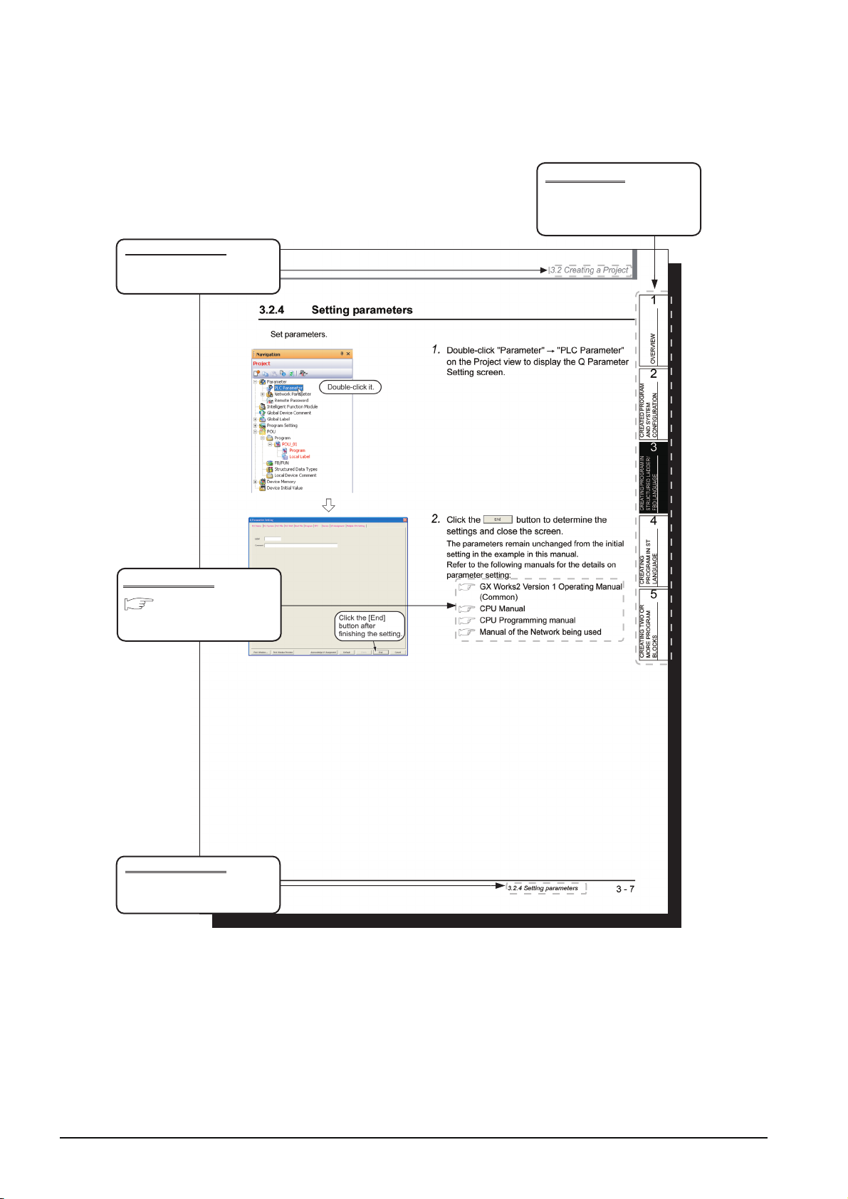
3.2.4 Setting parameters .......................................................................................................................3 - 7
3.2.5 Setting labels ................................................................................................................................3 - 8
3.2.6 Creating a program.....................................................................................................................3 - 11
3.2.7 Compiling a program .................................................................................................................. 3 - 19
3.2.8 Creating an FBD program ..........................................................................................................3 - 20
3.3 Writing a Project to the programmable controller 3 - 21
3.3.1 Connecting the personal computer to the programmable controller........................................... 3 - 21
3.3.2 Writing a project to the programmable controller........................................................................3 - 26
3.4 Monitoring Operations 3 - 29
3.4.1 Monitoring a program .................................................................................................................3 - 29
3.4.2 Batch monitoring of device values.............................................................................................. 3 - 34
A - 5
Page 8

3.5 Diagnosing the programmable controller 3 - 38
3.6 Reading a Project from programmable controller 3 - 39
3.7 Printing 3 - 41
3.7.1 Setting the printer....................................................................................................................... 3 - 41
3.7.2 Previewing a program ................................................................................................................ 3 - 42
3.7.3 Printing a program...................................................................................................................... 3 - 44
3.7.4 Previewing a PLC Parameter..................................................................................................... 3 - 45
3.7.5 Printing a PLC Parameter .......................................................................................................... 3 - 46
3.8 Saving a Project 3 - 47
3.9 Exiting GX Works2 3 - 48
4 CREATING PROGRAM IN ST LANGUAGE 4 - 1 to 4 - 12
4.1 Created Program 4 - 2
4.1.1 Operations of program ................................................................................................................. 4 - 2
4.1.2 Created program .......................................................................................................................... 4 - 2
4.2 Creating a Project 4 - 3
4.2.1 Starting GX Works2 ..................................................................................................................... 4 - 3
4.2.2 Screen configuration in GX Works2 ............................................................................................. 4 - 3
4.2.3 Creating a new project ................................................................................................................. 4 - 3
4.2.4 Setting parameters....................................................................................................................... 4 - 3
4.2.5 Setting labels................................................................................................................................ 4 - 3
4.2.6 Creating a program ...................................................................................................................... 4 - 4
4.2.7 Compiling a program.................................................................................................................... 4 - 6
4.3 Writing a Project to the programmable controller 4 - 7
4.4 Monitoring Operations 4 - 7
4.4.1 Monitoring a program ................................................................................................................... 4 - 7
4.4.2 Batch monitoring of device values ............................................................................................. 4 - 10
4.5 Diagnosing the programmable controller 4 - 11
4.6 Reading a Project from programmable controller 4 - 11
4.7 Printing 4 - 11
4.8 Saving a Project 4 - 11
4.9 Exiting GX Works2 4 - 11
5 CREATING TWO OR MORE PROGRAM BLOCKS 5 - 1 to 5 - 19
5.1 Created Program 5 - 2
5.1.1 Operations of program ................................................................................................................. 5 - 2
5.1.2 Created program .......................................................................................................................... 5 - 3
5.2 Creating a Project 5 - 4
5.2.1 Starting GX Works2 ..................................................................................................................... 5 - 4
5.2.2 Screen configuration in GX Works2 ............................................................................................. 5 - 4
5.2.3 Creating a new project ................................................................................................................. 5 - 4
5.2.4 Setting parameters....................................................................................................................... 5 - 4
A - 6
Page 9

5.2.5 Preparing (creating) the program configuration............................................................................5 - 5
5.2.6 Setting labels ................................................................................................................................5 - 8
5.2.7 Creating a program.......................................................................................................................5 - 9
5.2.8 Compiling a program .................................................................................................................. 5 - 11
5.3 Writing a Project to the programmable controller 5 - 12
5.4 Monitoring Operations 5 - 12
5.4.1 Monitoring a program .................................................................................................................5 - 12
5.4.2 Batch monitoring of device values.............................................................................................. 5 - 18
5.5 Diagnosing the programmable controller 5 - 18
5.6 Reading a Project from programmable controller 5 - 18
5.7 Printing 5 - 19
5.8 Saving a Project 5 - 19
5.9 Exiting GX Works2 5 - 19
A - 7
Page 10
■ MANUALS
Related manuals are separately issued according to the purpose of their functions in GX Works2.
● Related manuals
The manuals related to this product are shown below.
Refer to the following tables when ordering required manuals.
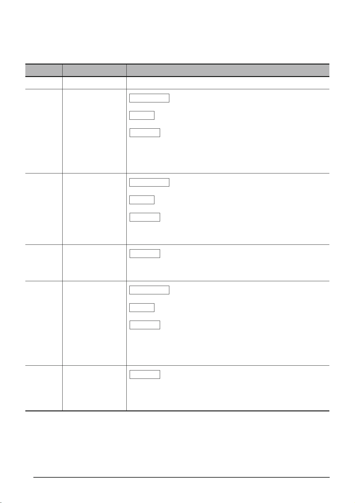
1) Operation of GX Works2
Manual name
GX Works2 Version 1 Operating Manual (Common)
Explains the system configuration of GX Works2 and the functions common to a Simple project and
Structured project such as parameter setting, operation method for the online function. (Sold separately)
GX Works2 Version 1 Operating Manual (Simple Project)
Explains operation methods such as creating and monitoring programs in Simple project of GX Works2.
(Sold separately)
GX Works2 Version 1 Operating Manual (Structured Project)
Explains operation methods such as creating and monitoring programs in Structured project of GX Works2.
(Sold separately)
GX Works2 Version 1 Operating Manual (Intelligent Function Module)
Explains operation methods of intelligent function module such as parameter setting, monitoring programs,
and predefined protocol support function in GX Works2. (Sold separately)
GX Works2 Beginner’s Manual (Simple Project)
Explains fundamental operation methods such as creating, editing, and monitoring programs in Simple
project for users inexperienced with GX Works2. (Sold separately)
2) Structured Programming
Manual name
MELSEC-Q/L/F Structured Programming Manual (Fundamentals)
Explains the programming method, types of programming languages and other information required to
create structured programs. (Sold separately)
Manual number
(Manual code)
SH-080779ENG
(13JU63)
SH-080780ENG
(13JU64)
SH-080781ENG
(13JU65)
SH-080921ENG
(13JU69)
SH-080787ENG
(13JZ22)
Manual number
(Manual code)
SH-080782ENG
(13JW06)
A - 8
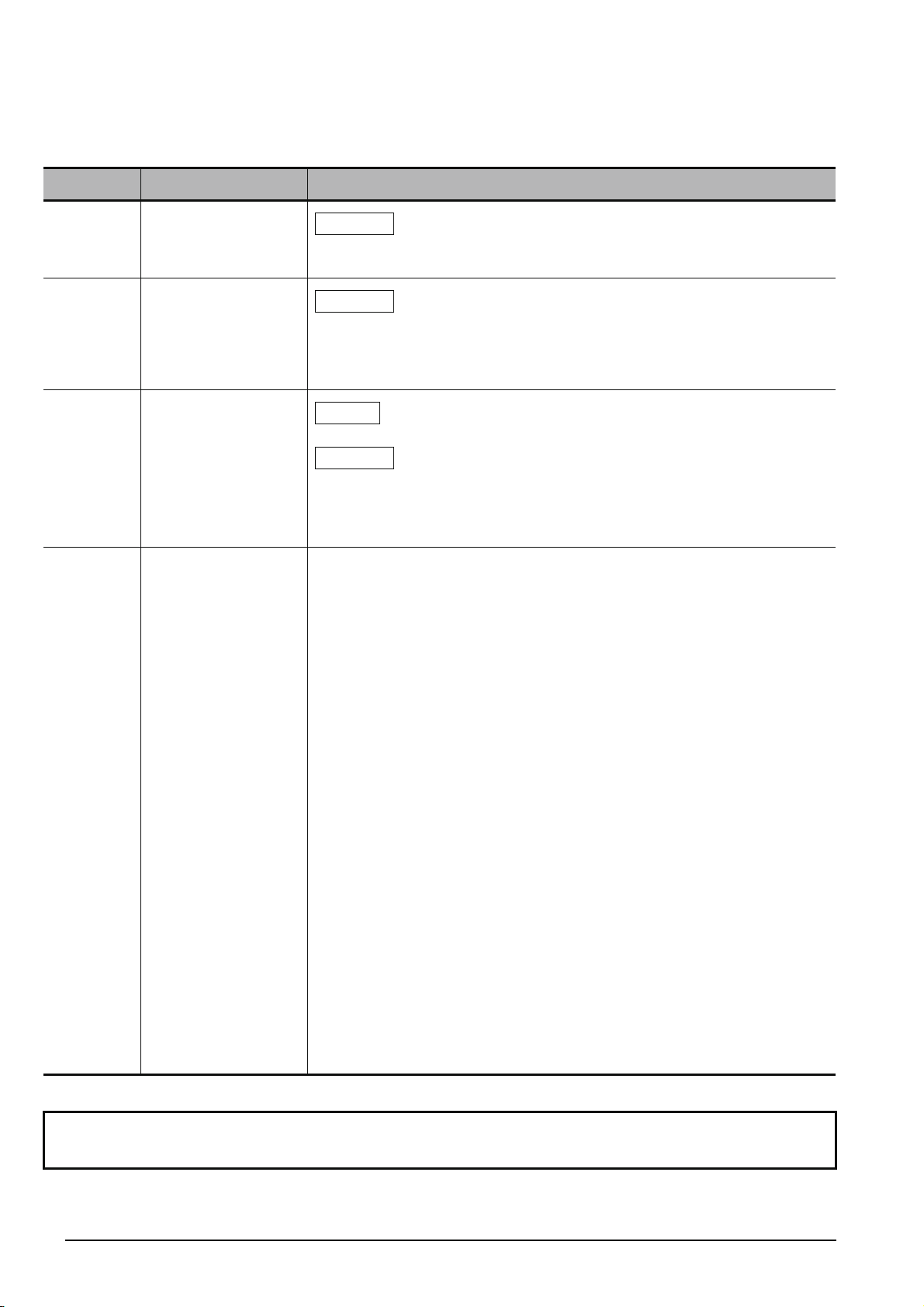
MELSEC-Q/L Structured Programming Manual (Common Instructions)
Explains the specifications and functions of common instructions such as sequence instructions, basic
instructions, and application instructions, that can be used in structured programs. (Sold separately)
MELSEC-Q/L Structured Programming Manual (Application Functions)
Explains the specifications and functions of application functions that can be used in structured programs.
(Sold separately)
MELSEC-Q/L Structured Programming Manual (Special Instructions)
Explains the specifications and functions of special instructions such as module dedicated instruction, PID
control instruction, and built-in I/O function dedicated instruction, that can be used in structured programs.
(Sold separately)
FXCPU Structured Programming Manual (Device & Common)
Explains the devices and parameters provided in GX Works2 for structured programming. (Sold separately)
FXCPU Structured Programming Manual (Basic & Applied Instruction)
Explains the sequence instructions provided in GX Works2 for structured programming. (Sold separately)
FXCPU Structured Programming Manual (Application Functions)
Explains the application functions provided in GX Works2 for structured programming. (Sold separately)
SH-080783ENG
(13JW07)
SH-080784ENG
(13JW08)
SH-080785ENG
(13JW09)
JY997D26001
(09R925)
JY997D34701
(09R926)
JY997D34801
(09R927)
Page 11

3) Operation of iQ Works
Manual name
iQ Works Beginner's Manual
Explains fundamental operation methods such as managing the system using MELSOFT Navigator and
using system labels for users inexperienced with GX Works2. (Sold separately)
The Operating Manuals are included on the CD-ROM of the software package in a PDF file format.
Manuals in printed form are sold separately for single purchase. Order a manual by quoting the manual
number (model code) listed in the table above.
Manual number
(Manual code)
SH-080902ENG
(13JZ44)
A - 9
Page 12
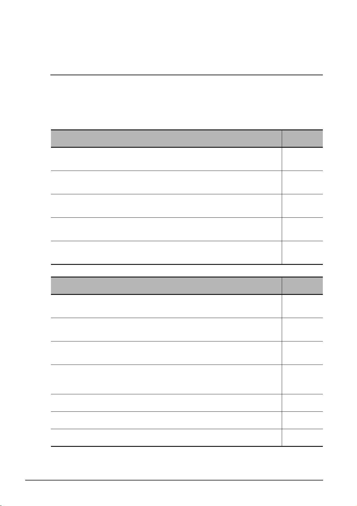
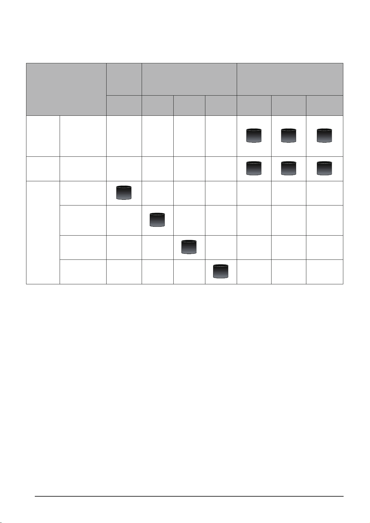
● Purpose of this manual
This manual explains the operation for creating sequence programs in Structured project, one of the
functions supported with GX Works2.
Manuals for reference are listed in the following table according to their purpose.
For information such as the contents and manual number of each manual, refer to the list of 'Related
manuals'.
1) Operation of GX Works2
Installation
Operation of
GX Works2
Purpose
Learning the operating
environment and
installation method
Learning all functions of
GX Works2
Learning the project
types and available
languages in GX Works2
Learning the basic
operations and operating
procedures when
creating a simple project
for the first time
Learning the basic
operations and operating
procedures when
creating a structured
project for the first time
Learning the operations
of available functions
regardless of project
type.
Learning the functions
and operation methods
for programming
Learning data setting
methods for intelligent
function module
GX Works2
Installation
Instructions
Details
GX Works2
Beginner’s Manual
Simple
Project
Details
Structured
Project
Details
Common
Outline
Outline
Details
Outline
GX Works2 Version 1
Operating Manual
Simple
Project
Details Details
Structured
Project
Intelligent
Function
Module
Details
A - 10
Page 13
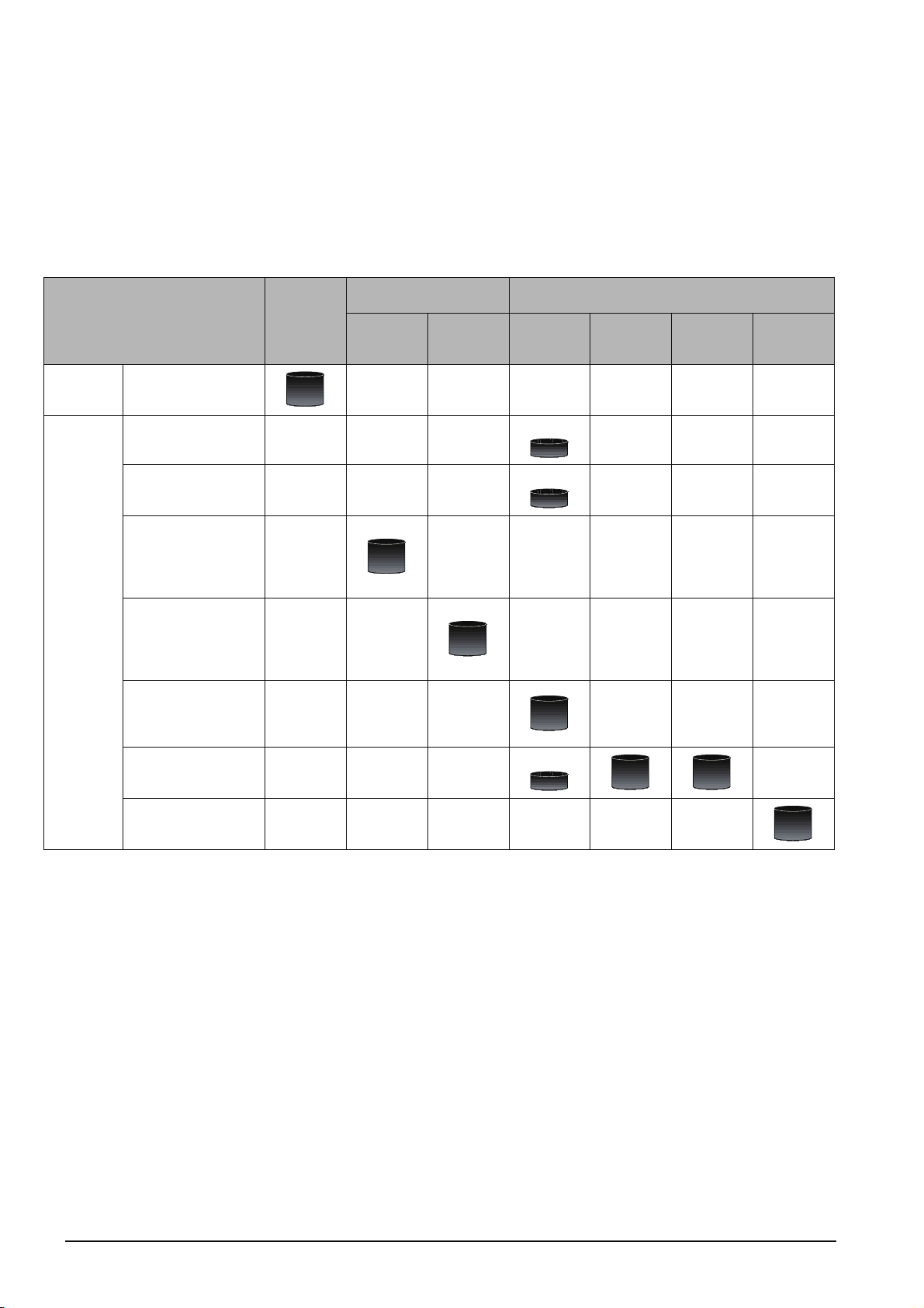
2) Operation of GX Works2
For details of instructions used in each programming language, refer to the section 3 on the next
page.
Purpose
Ladder
Simple
Project
SFC
ST
Ladder
SFC
Structured
Project
Structured Ladder/FBD
ST
*1: MELSAP3 and FX series SFC only
GX Works2
Installation
Instructions
GX Works2
Beginner’s Manual
Simple
Project
Outline
*1
Outline
Outline
*1
Outline
Structured
Project
Outline
Outline
Outline
Common
GX Works2 Version 1
Operating Manual
Simple
Project
Details
Details
Details
Details
Structured
Project
Details
Details
Details
Intelligent
Function
Module
A - 11
Page 14
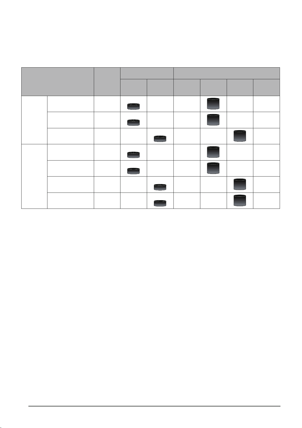
3) Details of instructions in each programming language (for QCPU (Q mode)/LCPU)
All
languages
Using
ladder
language
Using
SFC
language
Using
Structured
Ladder/
FBD or ST
language
Purpose
Learning details of
programmable
controller CPU
error codes,
special relays, and
special registers
Learning the types
and details of
common
instructions
Learning the types
and details of
instructions for
intelligent function
modules
Learning the types
and details of
instructions for
network modules
Learning the types
and details of
instructions for the
PID control
function
Learning details of
specifications,
functions, and
instructions of
SFC (MELSAP3)
Learning the
fundamentals for
creating a
structured
program
Learning the types
and details of
common
instructions
Learning the types
and details of
instructions for
intelligent function
modules
Learning the types
and details of
instructions for
network modules
Learning the types
and details of
instructions for the
PID control
function
Learning the types
and details of
application
functions
MELSEC-
Q/L/F
Structured
Programming
Manual
Fundamentals
Details
MELSEC-Q/L Structured
Programming Manual
Common
Instructions
Details
Instructions
Special
Outline
Outline
Outline
Application
Functions
Details
MELSEC-
Q/L
Programming
Manual
Common
Instructions
Details
Details
MELSEC-Q/L/QnA
Programming Manual
PID Control
Instructions
Details
Details
SFC -
Details
Manual for
module to
be used
Details
Details
Details
Details
A - 12
Page 15
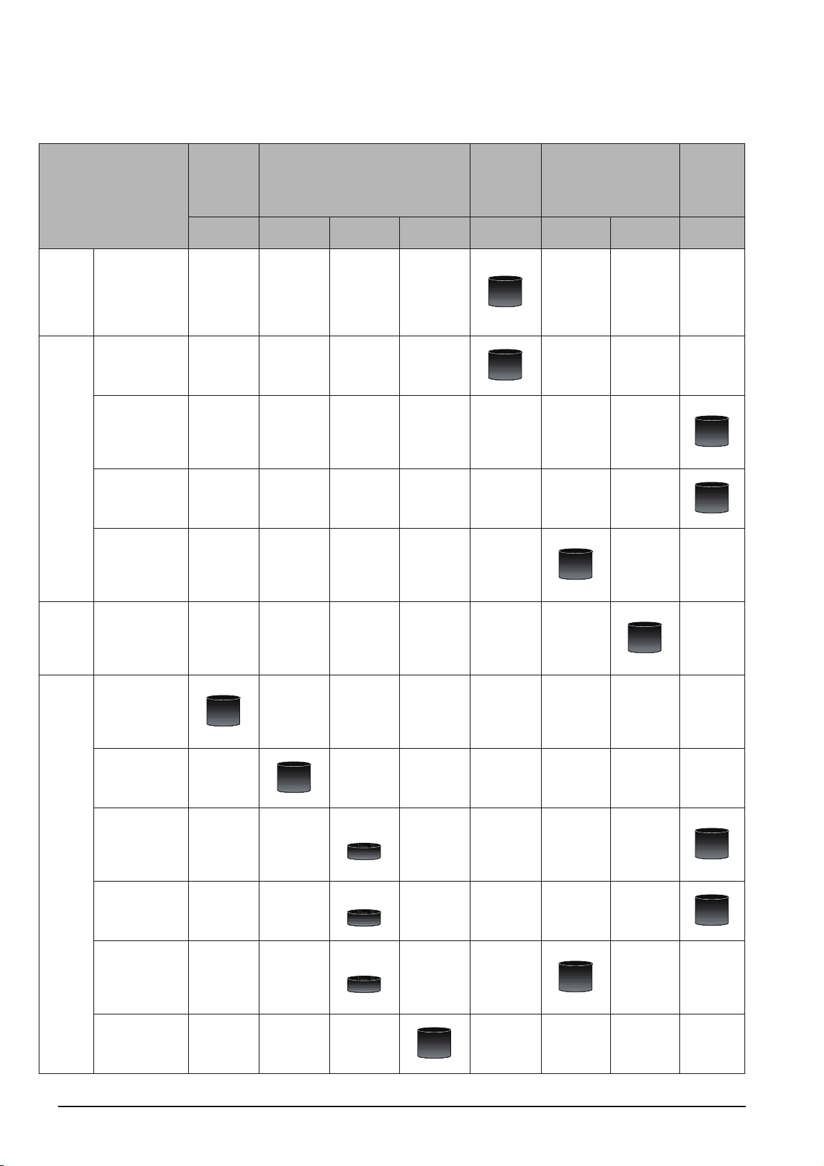
Using ladder
language
Using SFC
language
Using
Structure d
Ladder/FBD
or ST
language
4) Details of instructions in each programming language (for FXCPU)
MELSEC-
Q/L/F
Purpose
Learning the types
and details of
basic/application
instructions,
descriptions of
devices and
parameters
Learning details of
specifications,
functions, and
instructions of SFC
Learning the
fundamentals for
creating a
structured program
Learning the
descriptions of
devices,
parameters, and
error codes
Learning the types
and details of
sequence
instructions
Learning the types
and details of
application
instructions
Structured
Programming
Manual
Fundamentals
Details
FXCPU Structured Programming Manual
Device &
Common
Details
Basic &
Applied
Instruction
Details
Application
Functions
Details
FXCPU Programming Manual
FX0, FX0S,
FX
0N, FX1,
FX
U, FX2C
Details Details Details
Details Details Details
FX1S, FX1N,
FX
2N, FX1NC,
FX
2NC
FX3G, FX3U,
FX
3UC
A - 13
Page 16
● How to read this manual
Section title
Clarifies the section of currently
opened page.
Chapter heading
Index on the right of the page
number clarifies the chapter of
currently opened page.
Reference location
leads to the reference
location and reference manuals.
Section title
Clarifies the section of currently
opened page.
* Since the above page was created for explanation purpose, it differs from the actual page.
A - 14
Page 17
This manual also uses the following columns:
This explains notes for requiring attention or useful functions relating to the information given on the
same page.
Restrictions
This explains restrictions relating to the information given on the same page.
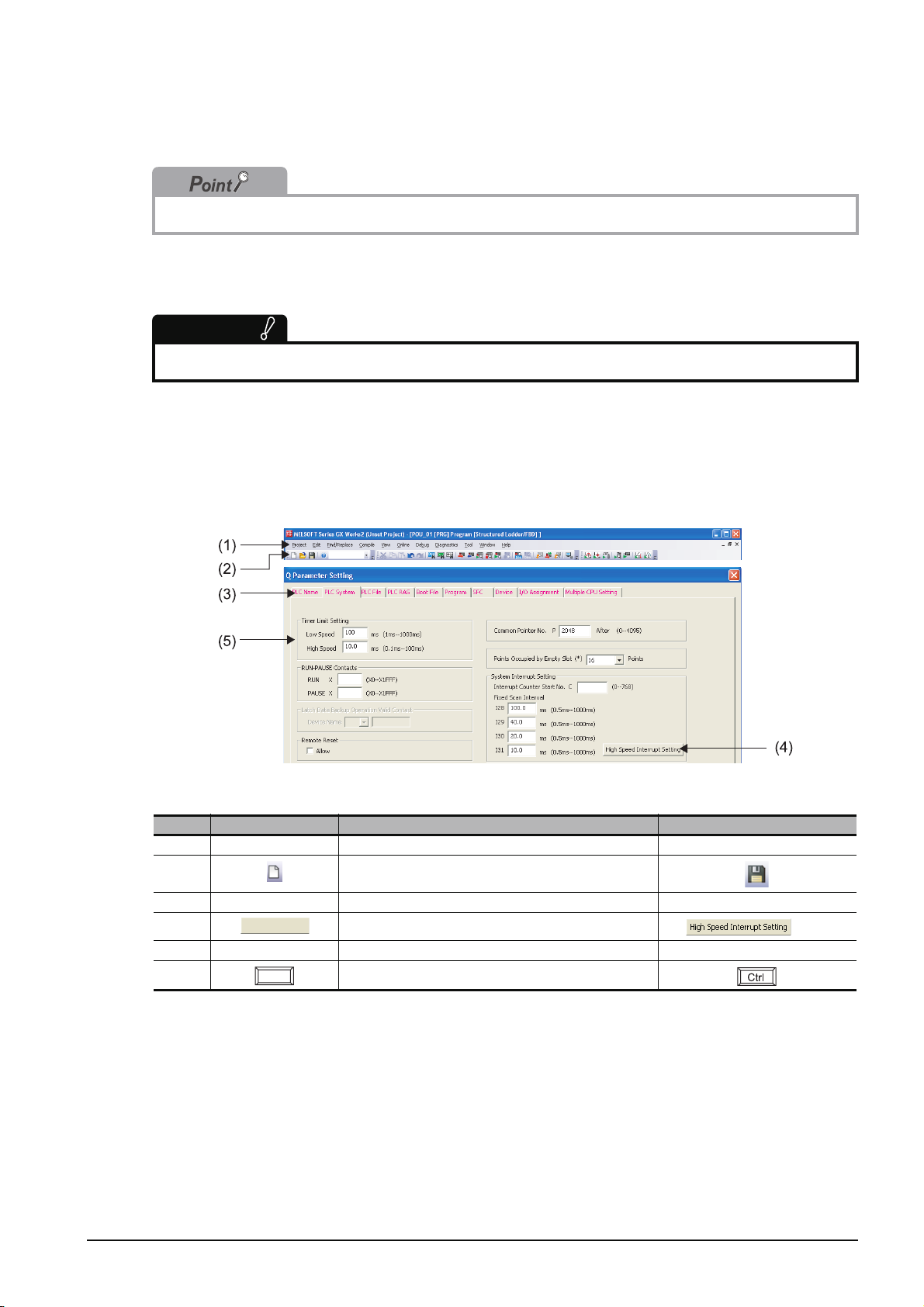
● Symbols used in this manual
The following shows the symbols used in this manual with descriptions and examples.
No. Symbol Description Example
(1) [ ] Menu name on a menu bar [Project]
(2) Toolbar icon
(3) << >> Tab name in a screen <<PLC System>>
(4) Button on a screen
(5) " " Item name in a screen "Timer Limit Setting"
− Keyboard key
button
A - 15
Page 18
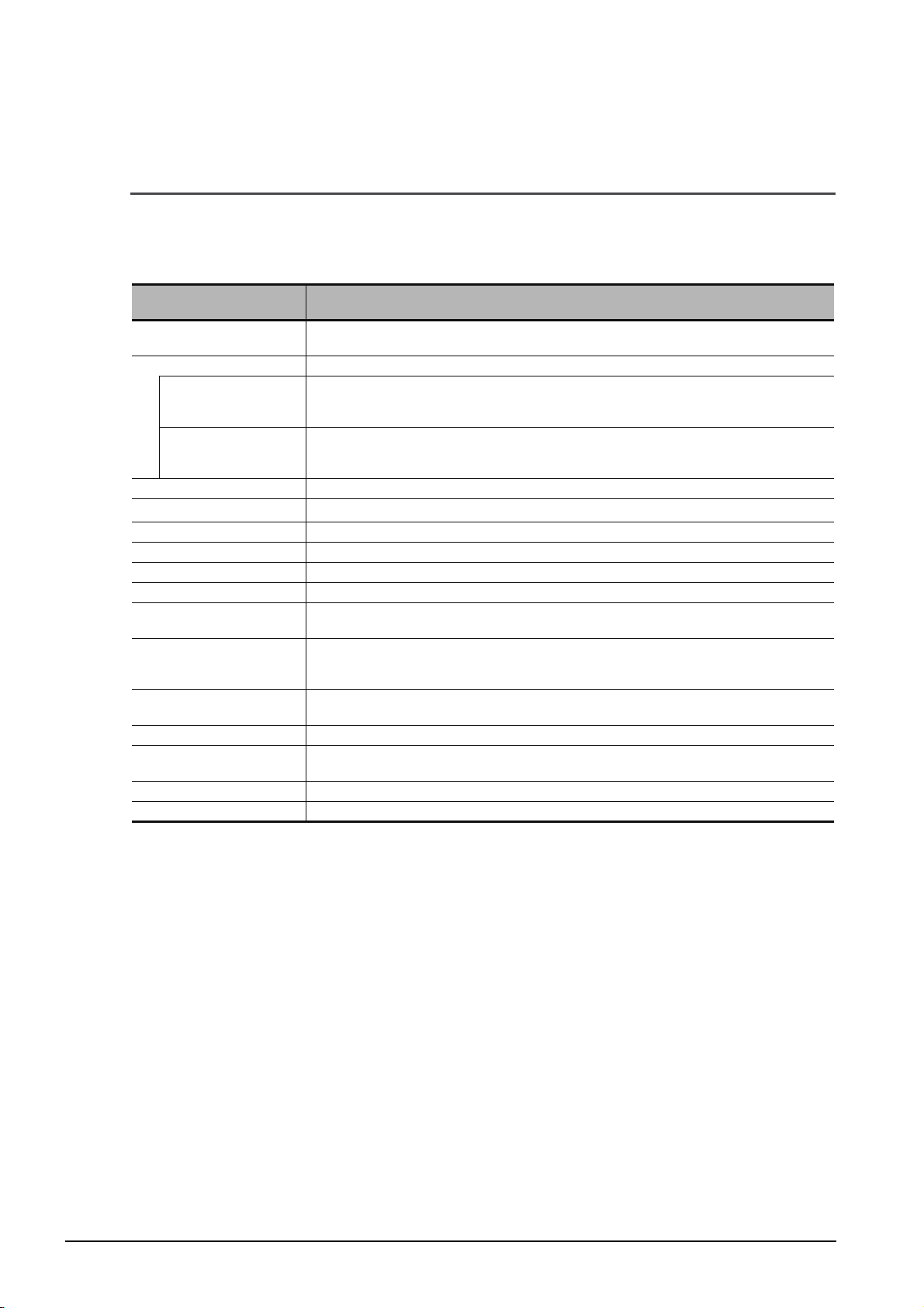
■ GENERIC TERMS AND ABBREVIATIONS IN THIS MANUAL
This manual uses the generic terms and abbreviations listed in the following table to discuss the
software packages and programmable controller CPUs. Corresponding module model names are also
listed if needed.
Generic terms and
Abbreviations
GX Works2
Existing application -
GX Developer
GX Simulator
iQ Works Abbreviation for iQ platform supporting engineering environment MELSOFT iQ Works
Personal computer
Q series Abbreviation for Mitsubishi programmable controller MELSEC-Q series
L series Abbreviation for Mitsubishi programmable controller MELSEC-L series
FX series Abbreviation for Mitsubishi programmable controller MELSEC-F series
Basic model QCPU Generic term for Q00J, Q00, Q01
High Performance model
QCPU
Universal model QCPU
QCPU (Q mode)
LCPU Generic term for L02, L02-P, L26-BT and L26-PBT
FXCPU
CPU module Generic term for QCPU (Q mode), LCPU, and FXCPU
SFC Generic term for MELSAP3, MELSAP-L, and FX series SFC
Generic product name for SWnDNC-GXW2-E model
(n: version)
Generic product name for SWnD5C-GPPW-E, SWnD5C-GPPW-EA, SWnD5C-GPPW-EV, and
SWnD5C-GPPW-EVA
(n: version)
Generic product name for SWnD5C-GPPW-E, SWnD5C-GPPW-EA, SWnD5C-GPPW-EV, and
SWnD5C-GPPW-EVA
(n: version)
Generic term for personal computers on which Windows
Generic term for Q02, Q02H, Q06H, Q12H, and Q25H
Generic term for Q00UJ, Q00U, Q01U, Q02U, Q03UD, Q03UDE, Q04UDH, Q04UDEH,
Q06UDH, Q06UDEH, Q10UDH, Q10UDEH, Q13UDH, Q13UDEH, Q20UDH, Q20UDEH,
Q26UDH, Q26UDEH, Q50UDEH, and Q100UDEH
Generic term for Basic model QCPU, High Performance model QCPU, and Universal model
QCPU
Generic term for FX
and FX
3UC
0, FX0S, FX0N, FXU, FX2C, FX1S, FX1N, FX1NC, FX2N, FX2NC, FX3G, FX3U,
Description
®
operates
A - 16
Page 19
1
OVERVIEW
1OVERVIEW
This manual explains the procedures to actually create a program (Structured Project) using GX Works2 and
operate the programmable controller using the created program.
If this is your first time creating a Structured Project using GX Works2, you are recommended to read this
manual first, and then use GX Works2.
Refer to the following manual for Simple Projects:
GX Works2 Beginner’s Manual (Simple Project)
1.1 Simple Project and Structured Project . . . . . . . . . . . . . . . . . . . 1-2
1.2 Program Creation Procedure . . . . . . . . . . . . . . . . . . . . . . . . . . . 1-4
2
CREATED PROGRAM
AND SYSTEM
CONFIGURATION
3
CREATING PROGRAM IN
STRUCTURED LADDER/
FBD LANGUAGE
4
CREATING
PROGRAM IN ST
LANGUAGE
5
CREATING TWO OR
MORE PROGRAM
BLOCKS
1 - 1
Page 20

GX Works2
1 OVERVIEW
1.1 Simple Project and Structured Project
■ Simple Project
In a Simple Project, you can create sequence programs using instructions for the Mitsubishi
programmable controller CPU.
The Simple Project offers the same operability for program creation as the conventional GX Developer.
You can create sequence programs using the following programming languages:
● Graphic languages
• Ladder
Use this graphic language to describe programs as ladders consisting of contacts, coils, etc.,
using the same operating procedures as the conventional GX Developer.
•SFC
Use this graphic language to describe sequence control in a way easy to understand.
Describe steps which specify the processing and transition conditions which specify conditions
for proceeding to the next step.
You can describe steps and transition conditions using the ladder language.
● Text language
• ST (Structured Text)
This text language allows you to describe controls by syntax including alternative sequences
offered by conditional sentences and repetition offered by repetition sentences in the same way
as high-level languages such as the C language. Accordingly, you can briefly create programs
easy to look at.
■ Structured Project
In a Structured Project, you can create programs by structured program.
By dividing controls into small portions and making parts of common contents, you can create programs
easy to understand and applicable to many cases (by structured program.)
You can create sequence programs using the following programming languages:
● Graphic languages
• Ladder
Use this graphic language to describe programs as ladders consisting of contacts, coils, etc.,
using the same operating procedures as the conventional GX Developer.
• Structured Ladder/FBD
Structured Ladder is created based on the relay circuit design technology. Because this
language is easy to understand intuitively, it is used generally for sequence programs.
Every ladder always starts from a base line on the left.
Structured Ladder consists of contacts, coils, function blocks and functions which are connected
each other with vertical lines and horizontal lines.
FBD connects functions and function blocks with ruled lines to describe ladders.
•SFC
Use this graphic language to describe sequence control in a way easy to understand.
Describe steps which specify the processing and transition conditions which specify conditions
for proceeding to the next step.
You can describe steps and transition conditions using the ladder language.
1 - 2
Page 21
1.1 Simple Project and Structured Project
● Text language
• ST (Structured Text)
This text language allows you to describe controls by syntax including alternative sequences
offered by conditional sentences and repetition offered by repetition sentences in the same way
as high-level languages such as the C language. Accordingly, you can briefly create programs
easy to look at.
Restrictions
The FXCPU does not support the ST language in Simple Project, and does not support the ladder language
and SFC language in Structured Project.
1
OVERVIEW
2
CREATED PROGRAM
AND SYSTEM
CONFIGURATION
3
CREATING PROGRAM IN
STRUCTURED LADDER/
FBD LANGUAGE
4
CREATING
PROGRAM IN ST
LANGUAGE
5
CREATING TWO OR
MORE PROGRAM
BLOCKS
1 - 3
Page 22
GX Works2
1 OVERVIEW
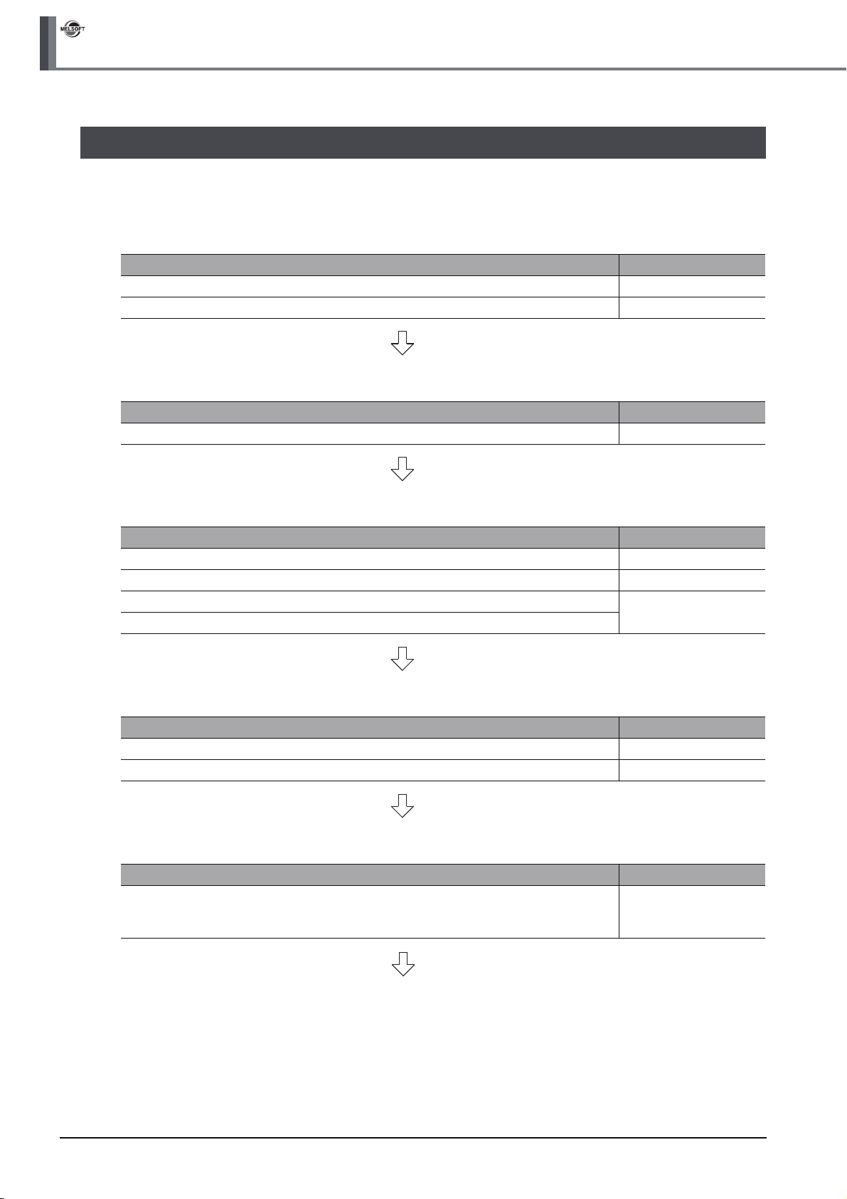
1.2 Program Creation Procedure
The figure below shows how to create a program with a Structured Project and execute it in a programmable
controller CPU.
1. Opening a project
Procedure Reference
Start GX Works2. 3.2.1
Create a new Structured Project. Or open an existing Structured Project. 3.2.3
2. Setting parameters
Procedure Reference
Set the parameters. 3.2.4
3. Creating the program configuration
Procedure Reference
Create Program File. --
Create Task in Program File. --
Create POU.
Register program block of POU to Task in Program File.
5.2.5
4. Setting labels
Procedure Reference
Define global labels. 3.2.5
Define local labels. --
5. Editing the program
Procedure Reference
3.2.6
Edit the program in each POU.
4.2.6
5.2.7
1 - 4
(To the next page)
Page 23
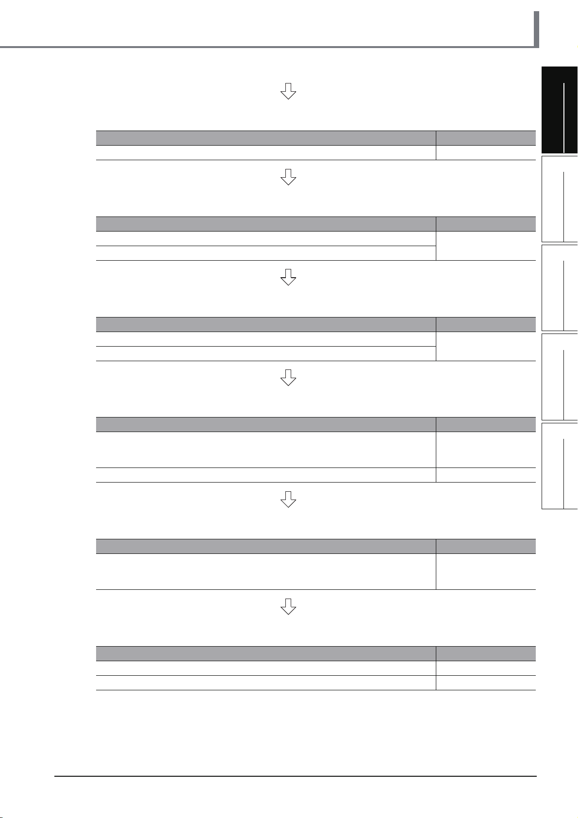
6. Conversion
1.2 Program Creation Procedure
1
Procedure Reference
Compile the program. 3.2.7
7. Connecting the programmable controller CPU
Procedure Reference
Connect the personal computer to the programmable controller CPU.
Set the connection destination.
3.3.1
8. Writing to the programmable controller
Procedure Reference
Write the parameters to the programmable controller CPU.
Write the program to the programmable controller CPU.
3.3.2
9. Checking operations
Procedure Reference
3.4
Monitor the sequence program execution status, and check operations.
Check for errors in the programmable controller. 3.5
4.4
5.4
OVERVIEW
2
CREATED PROGRAM
AND SYSTEM
CONFIGURATION
3
CREATING PROGRAM IN
STRUCTURED LADDER/
FBD LANGUAGE
4
CREATING
PROGRAM IN ST
LANGUAGE
5
10.Printing
Procedure Reference
Print the program and parameters.
11.Exiting GX Works2
Procedure Reference
Save the project. 3.8
Exiting GX Works2. 3.9
3.7
4.7
5.7
CREATING TWO OR
MORE PROGRAM
BLOCKS
1 - 5
Page 24

GX Works2
1 OVERVIEW
MEMO
1 - 6
Page 25
1
OVERVIEW
2 CREATED PROGRAM AND
SYSTEM CONFIGURATION
This chapter explains the system configuration and gives an overview of the program created by using this
manual.
2.1 System Configuration . . . . . . . . . . . . . . . . . . . . . . . . . . . . . . . . . 2-2
2.2 Overview of Program Creation. . . . . . . . . . . . . . . . . . . . . . . . . . 2-2
2
CREATED PROGRAM
AND SYSTEM
CONFIGURATION
3
CREATING PROGRAM IN
STRUCTURED LADDER/
FBD LANGUAGE
4
CREATING
PROGRAM IN ST
LANGUAGE
5
CREATING TWO OR
MORE PROGRAM
BLOCKS
2 - 1
Page 26
GX Works2
2 CREATED PROGRAM AND SYSTEM CONFIGURATION
2.1 System Configuration
This manual uses GX Works2 and the Q Series programmable controller for explanation.
Programmable controller (QCPU)
GX Works2
USB cable
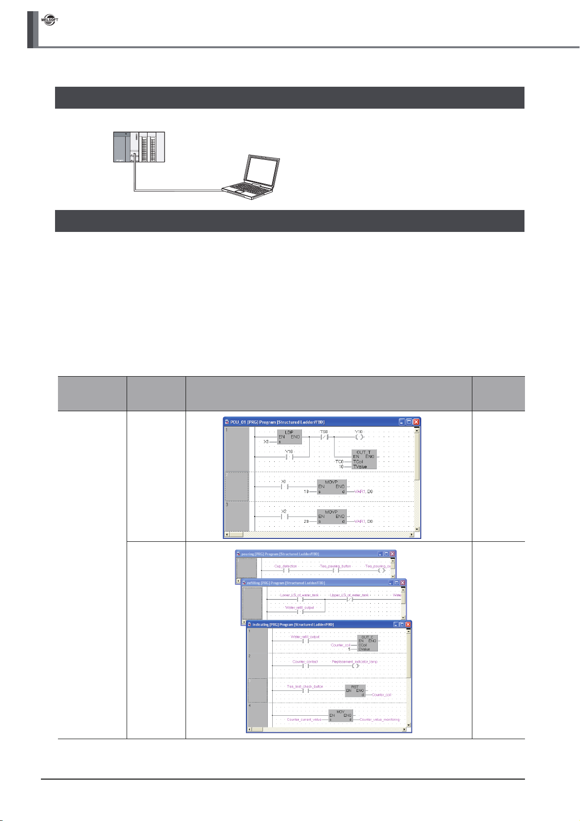
2.2 Overview of Program Creation
This manual explains the following program creation procedures using the simple example program shown in
the table below.
• Creating a new project
• Setting parameters
• Setting labels
• Creating a program (inputting contacts and application instructions, converting ladder blocks and compiling
the program)
• Writing to the programmable controller
• Monitoring ladder, etc.
• Preview, Printing
Program
language
Number of
program
blocks
Table 2.1 Overview of created program
Operation overview Reference
Structured
Ladder
1 Chapter 3
3 Chapter 5
2 - 2
Page 27
2.2 Overview of Program Creation
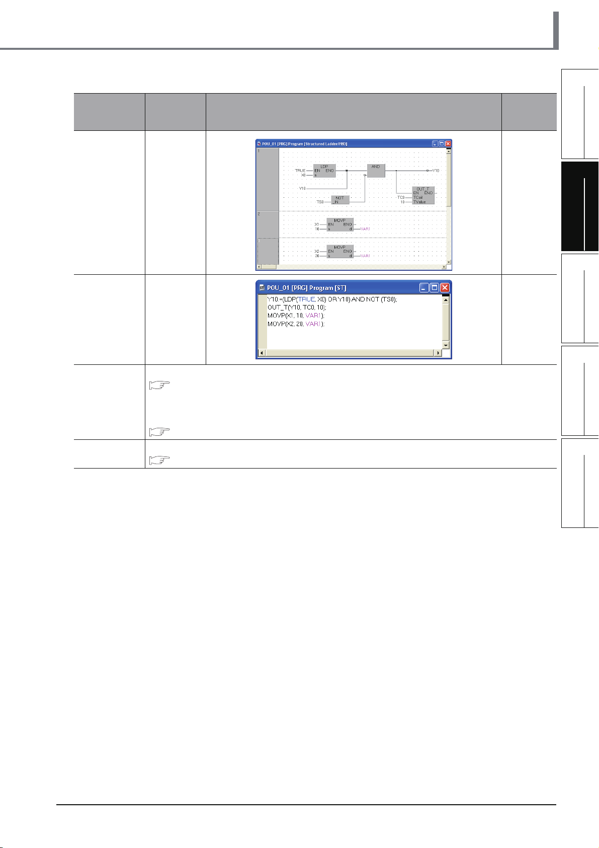
Table 2.1 Overview of created program
Program
language
FBD 1 Chapter 3
ST 1 Chapter 4
Number of
program
blocks
Operation overview Reference
1
OVERVIEW
2
CREATED PROGRAM
AND SYSTEM
CONFIGURATION
3
CREATING PROGRAM IN
STRUCTURED LADDER/
FBD LANGUAGE
4
Ladder
SFC
Refer to the following manual.
GX Works2 Beginner's Manual (Simple Project)
You can create the Inline ST Box that displays ST language programs in the Ladder Editor, and edit
and monitor ST language programs.
Refer to the following manual for the details.
GX Works2 Version 1 Operating Manual (Simple Project)
Refer to the following manual.
GX Works2 Beginner's Manual (Simple Project)
CREATING
PROGRAM IN ST
LANGUAGE
5
CREATING TWO OR
MORE PROGRAM
BLOCKS
2 - 3
Page 28

GX Works2
2 CREATED PROGRAM AND SYSTEM CONFIGURATION
MEMO
2 - 4
Page 29
1
OVERVIEW
3 CREATING PROGRAM IN
STRUCTURED LADDER/
FBD LANGUAGE
This chapter explains how to create a program in the Structured Ladder/FBD language with a Structured
Project using a simple Structured Ladder program.
Refer to the following manuals for the details on structured programs including programming languages,
labels, data types and functions (instructions):
MELSEC-Q/L/F Structured Programming Manual (Fundamentals)
Structured Programming Manual of the programmable controller CPU
3.1 Created Program . . . . . . . . . . . . . . . . . . . . . . . . . . . . . . . . . . . . . 3-2
3.2 Creating a Project . . . . . . . . . . . . . . . . . . . . . . . . . . . . . . . . . . . . 3-3
3.3 Writing a Project to the programmable controller . . . . . . . . . 3-21
3.4 Monitoring Operations . . . . . . . . . . . . . . . . . . . . . . . . . . . . . . . 3-29
3.5 Diagnosing the programmable controller. . . . . . . . . . . . . . . . 3-38
3.6 Reading a Project from programmable controller . . . . . . . . . 3-39
3.7 Printing. . . . . . . . . . . . . . . . . . . . . . . . . . . . . . . . . . . . . . . . . . . . 3-41
3.8 Saving a Project . . . . . . . . . . . . . . . . . . . . . . . . . . . . . . . . . . . . 3-47
3.9 Exiting GX Works2 . . . . . . . . . . . . . . . . . . . . . . . . . . . . . . . . . . 3-48
2
CREATED PROGRAM
AND SYSTEM
CONFIGURATION
3
CREATING PROGRAM IN
STRUCTURED LADDER/
FBD LANGUAGE
4
CREATING
PROGRAM IN ST
LANGUAGE
5
CREATING TWO OR
MORE PROGRAM
BLOCKS
3 - 1
Page 30
GX Works2
3 CREATING PROGRAM IN STRUCTURED LADDER/FBD LANGUAGE
3.1 Created Program
This section explains the operations of the program to be created and ladder programs.
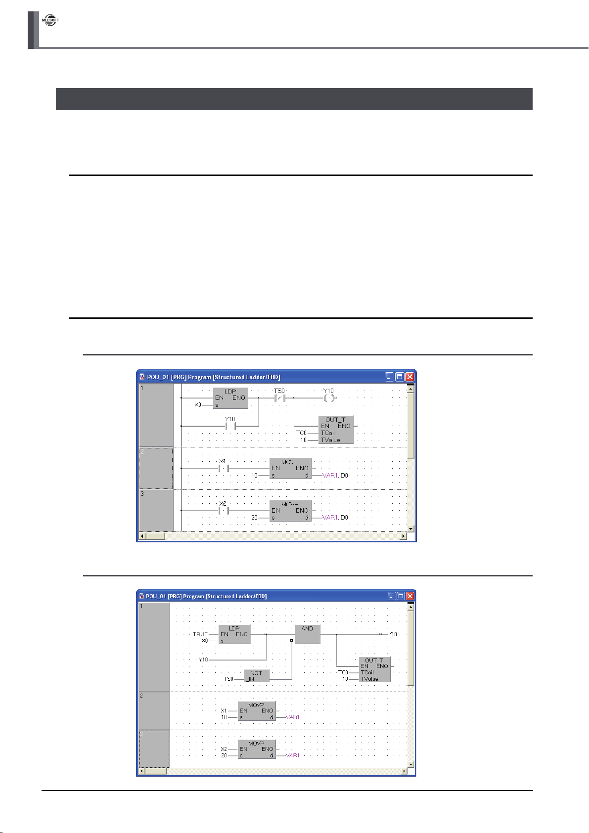
3.1.1 Operations of program
● When X0 turns ON, the programmable controller turns ON Y10, and then turns OFF Y10 1 second
later.
● When X1 turns ON, the programmable controller transfers K10 to D0 (which is defined with the
LABEL "VAR1").
● When X2 turns ON, the programmable controller transfers K20 to D0 (which is defined with the
LABEL "VAR1").
3.1.2 Created program
■ In the case of Structured Ladder
■ In the case of FBD
3 - 2
3.1.1 Operations of program
Page 31
3.2 Creating a Project
Create a project using Structured Ladder programs.
Refer to Section 3.2.8 for creating an FBD program.
3.2 Creating a Project
1
OVERVIEW
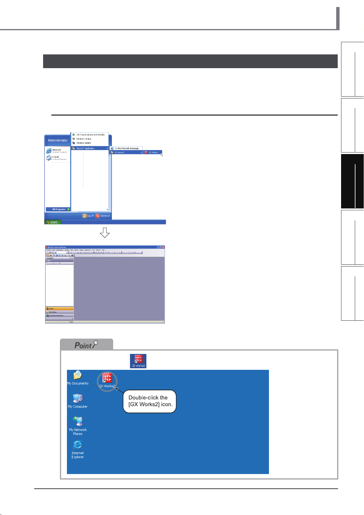
3.2.1 Starting GX Works2
1. Select the software package menu to be
started.
2. The selected software package is started.
2
CREATED PROGRAM
AND SYSTEM
CONFIGURATION
3
CREATING PROGRAM IN
STRUCTURED LADDER/
FBD LANGUAGE
4
CREATING
PROGRAM IN ST
LANGUAGE
5
You can double-click the icon on the desktop to start the software package.
CREATING TWO OR
MORE PROGRAM
BLOCKS
3.2.1 Starting GX Works2
3 - 3
Page 32

GX Works2
3 CREATING PROGRAM IN STRUCTURED LADDER/FBD LANGUAGE
3.2.2 Screen configuration in GX Works2
The GX Works2 screen has the following configuration.
Select "View" or "Hide" in the [View] menu for each of the Toolbar, Status bar, Navigation Window,
Function Block Selection window and Output window.
Refer to the following manual for the details on the GX Works2 screen configuration:
Title bar
Menu bar
Toolbar
Navigation Window
GX Works2 Version 1 Operating Manual (Common)
Function Block selection
window
Displays the list of
function blocks available
to program creation.
View contents display area
Displays the contents of
the currently selected view.
View selection area
Allows selection of the
view to be displayed.
Work window
Used for programming,
parameter setting,
monitoring, etc.
Output window
Displays the compile
result, error information
and warning information.
Status bar
3 - 4
3.2.2 Screen configuration in GX Works2
Page 33

3.2.3 Creating a new project
At first, create a project.
3.2 Creating a Project
1. Perform either procedure below to display the
New Project screen.
• Select [Project] [New].
• Click (New).
2. Select the "Project Type", "PLC Series", "PLC
Type" and "Language" from the list boxes for
the new project to be created.
After the setting, click the button.
Settings
• Project Type : Structured Project
• PLC Series : QCPU (Q mode)
• PLC Type : Q02/Q02H
• Language : Structured Ladder/FBD
*1: Labels are always available in structured
projects. You do not have to check "Use Label".
*1
1
OVERVIEW
2
CREATED PROGRAM
AND SYSTEM
CONFIGURATION
3
CREATING PROGRAM IN
STRUCTURED LADDER/
FBD LANGUAGE
4
CREATING
PROGRAM IN ST
LANGUAGE
5
3. GX Works2 creates a new project.
CREATING TWO OR
MORE PROGRAM
BLOCKS
3.2.3 Creating a new project
3 - 5
Page 34

GX Works2
3 CREATING PROGRAM IN STRUCTURED LADDER/FBD LANGUAGE
Opening an existing project
Refer to the following manual for the details on the existing project opening procedure:
GX Works2 Version 1 Operating Manual (Common)
1. Perform either operation below.
• Select [Project] [Open].
• Click (Open).
2. The Open Project screen appears.
Select an existing project to be opened in the "Workspace Location" and "Workspace/
Project List".
Specify the existing
project to be opened.
The selected project
is displayed in
"Project Name".
3. Click the button to open the selected project.
Specify the "Workspace
Location" saving an
existing project to be
opened. The selected
folder is displayed in
"Workspace Name".
3 - 6
3.2.3 Creating a new project
Page 35

3.2.4 Setting parameters
Set parameters.
Double-click it.
3.2 Creating a Project
1. Double-click "Parameter" "PLC Parameter"
on the Project view to display the Q Parameter
Setting screen.
1
OVERVIEW
2
CREATED PROGRAM
AND SYSTEM
CONFIGURATION
3
Click the [End]
button after
finishing the setting.
2. Click the button to determine the
settings and close the screen.
The parameters remain unchanged from the initial
setting in the example in this manual.
Refer to the following manuals for the details on
parameter setting:
GX Works2 Version 1 Operating Manual
(Common)
CPU Manual
CPU Programming manual
Manual of the Network being used
CREATING PROGRAM IN
STRUCTURED LADDER/
FBD LANGUAGE
4
CREATING
PROGRAM IN ST
LANGUAGE
5
CREATING TWO OR
MORE PROGRAM
BLOCKS
3.2.4 Setting parameters
3 - 7
Page 36

GX Works2
3 CREATING PROGRAM IN STRUCTURED LADDER/FBD LANGUAGE
3.2.5 Setting labels
Set Global Labels.
1. Double-click "Global Label" "Global1" on the
Project view to display the Global Label Setting
screen.
2. Select the "Class" from the list box on the
Global Label Setting screen.
Settings
• Class: VAR_GLOBAL
3. Directly input the "Label Name" on the Global
Label Setting screen.
Settings
• Label Name: VAR1
3 - 8
Restrictions
● Characters available for the label name
You can enter up to 32 characters as the label name.
However, note that the following label name will cause a compile error.
• Label name which contains space
• Label name whose first character is a number
• Label name equivalent to a device name
For other characters unavailable for the label name, refer to the following manual.
GX Works2 Version 1 Operating Manual (Common)
(To the next page)
3.2.5 Setting labels
Page 37

3.2 Creating a Project
4. Directly input the "Date Type" on the Global
Label Setting screen.
Settings
• Date Type: Word [Signed]
You can click to display the Type Selection screen, and then select the Types on this screen.
Settings
1) Libraries : ALL
2) Type Class : Simple Types
3) Types : Word [Signed]
4) Array Element : Not checked
*1: Set "Libraries", "Type Class", "Types" and "Array
*1
Element" in this order.
1
OVERVIEW
2
CREATED PROGRAM
AND SYSTEM
CONFIGURATION
3
CREATING PROGRAM IN
STRUCTURED LADDER/
FBD LANGUAGE
4
(To the next page)
After completing the setting, click the button.
5. Directly input the "Device" on the Global Label
Setting screen.
Inputting "Device" in GX Works2 automatically sets
"Address".
In the same way, inputting "Address" automatically
sets "Device".
Settings
• Device: D0
CREATING
PROGRAM IN ST
LANGUAGE
5
CREATING TWO OR
MORE PROGRAM
BLOCKS
3.2.5 Setting labels
3 - 9
Page 38

GX Works2
3 CREATING PROGRAM IN STRUCTURED LADDER/FBD LANGUAGE
6. Set the "Constant", "Comment" and "Remark"
on the Global Label Setting screen.
"Relation with System Label", "System Label Name"
and "Attribute" are not used in examples shown in
this manual.
Settings
• Constant : When the label class is
"VAR_GLOBAL", you cannot set or
change the initial value.
• Comment : No setting
• Remark : No setting
Refer to the following manual for the details on the global label/local label setting procedure:
GX Works2 Version 1 Operating Manual (Structured Project)
Refer to the following manual for the details on the programming of global labels and labels:
MELSEC-Q/L/F Structured Programming Manual (Fundamentals)
3 - 10
3.2.5 Setting labels
Page 39

3.2.6 Creating a program
Create the Structured ladder/FBD program shown in Section 3.1.2.
1. Double-click "POU" "Program"
"POU_01" "Program" on the Project view to
display the POU_01 [PRG] Program [Structured
Ladder/FBD] screen.
Double-click it.
3.2 Creating a Project
1
OVERVIEW
2
CREATED PROGRAM
AND SYSTEM
CONFIGURATION
3
2. Drag "Function" "LDP" from the Function
Block Selection window, and drop it on the
POU_01 [PRG] Program [Structured Ladder/
FBD] screen to position it there.
Position "LDP".
Positioning Function and Function block using the Function Block Selection window
You can easily position Function and Function block by dragging them from the Function Block Selection
window.
Perform the following procedure to display the Function Block Selection Window:
Select "View" "Docking window" "Function Block Selection Window".
In the example below, drag the Function "LDP" from the Function Block Selection window, and drop it on the
POU_01 [PRG] Program [Structured Ladder/FBD] screen to position it there.
Refer to the following manual for the details:
GX Works2 Version 1 Operating Manual (Structured Project)
CREATING PROGRAM IN
STRUCTURED LADDER/
FBD LANGUAGE
4
CREATING
PROGRAM IN ST
LANGUAGE
5
CREATING TWO OR
MORE PROGRAM
BLOCKS
2) Drop it.
1) Drag it.
Using ladder symbols instead of the Function "LDP (Rising Edge)"
Click (Rising Edge) on the structured ladder/FBD toolbar, and then click a desired location to position the
Rising Edge there.
(To the next page)
3.2.6 Creating a program
3 - 11
Page 40

GX Works2
3 CREATING PROGRAM IN STRUCTURED LADDER/FBD LANGUAGE
Start Point End Point
Connection with grid line
Connect ladder symbols such as contacts, coils, Function and Function block with grid lines.
Click (Interconnect Mode), and draw a grid line.
Turn ON the Auto Connect function in the interconnect mode to easily draw a grid line only by specifying the
start point and end point using the mouse.
Refer to the following manual for the details:
GX Works2 Version 1 Operating Manual (Structured Project)
Start Point End Point
3. Click (Interconnect Mode) on the Structured
Ladder/FBD toolbar to specify the Interconnect
mode.
Click the start point and end point in this order to
draw a grid line as shown left.
(GX Works2 is using the Auto Connect function
described in "Point".)
Perform either of the following procedures to turn ON the Auto Connect function.
● Select [Edit] [Auto Connect] to put a check mark.
● Right-click the Structured Ladder/FBD work window to display the menu, and select "Auto Connect" to put a check
mark.
Click it.
4. Click (Select Mode) on the Structured
Ladder/FBD toolbar to specify the Select mode.
3 - 12
(To the next page)
3.2.6 Creating a program
Page 41

3.2 Creating a Project
5. Set the function "LDP".
Click the input variable "?" of "s", and set the input
variable.
Input Variable
Referring to the data type of input/output labels in a Function or Function block
Double-click a positioned function or function block to display the Function/FB Label Setting screen where you
can refer to the data type of labels.
Refer to the following manual for the details:
GX Works2 Version 1 Operating Manual (Structured Project)
Double-click it to
display the screen.
Settings
•s: X0
1
OVERVIEW
2
CREATED PROGRAM
AND SYSTEM
CONFIGURATION
3
CREATING PROGRAM IN
STRUCTURED LADDER/
FBD LANGUAGE
6. Click (Open Contact) on the Structured
Ladder/FBD toolbar, and then move the cursor
to a desired position to display an open contact
there. Click the open contact to connect it with
the left bus line and enable setting of a variable.
(GX Works2 is using the Auto Connect function
described in "Point".)
Settings
• Variable: Y10
Automatic connection with grid lines
While the Auto Connect function is ON, you can easily connect network elements such as contacts and coils
with connection points on the right side of left bus lines, vertical grid lines, contacts, coils, functions and
function blocks.
Refer to the following manual for the details.
GX Works2 Version 1 Operating Manual (Structured Project)
4
CREATING
PROGRAM IN ST
LANGUAGE
5
CREATING TWO OR
MORE PROGRAM
BLOCKS
(To the next page)
Select a connection point by moving the cursor, and click there
to automatically connect the connection point.
For avoiding automatic connection, lay out network elements
while pressing and holding the button.
3.2.6 Creating a program
3 - 13
Page 42

GX Works2
3 CREATING PROGRAM IN STRUCTURED LADDER/FBD LANGUAGE
7. Click (Close contact) on the Structured
Ladder/FBD toolbar, and then move the cursor
to a desired position to display a close contact
there.
Click the close contact to connect it with a
function of the LDP and enable setting of a
variable.
Settings
• Variable: TS0
*1: "TS0" indicates a contact of the timer T0.
*1
8. Draw a grid line on the left figure (position 1)
using the procedure described in the step 3.
1)
After drawing grid lines, click (Select Mode) on
the Structured Ladder/FBD toolbar to specify the
Select mode.
9. Click (Coil) on the Structured Ladder/FBD
toolbar, and then move the cursor to a desired
position to display a coil there.
Click the coil to connect it with the close contact
"TS0" and enable setting of a variable.
After drawing grid lines, click (Select Mode) on
the Structured Ladder/FBD toolbar to specify the
Select mode.
Settings
• Variable: Y10
10.Select "Function" "OUT_T" on the Function
Block Selection window, drag it, and drop it in a
desired position to position "OUT_T" there.
3 - 14
Input variables
TCoil and TValue
(To the next page)
3.2.6 Creating a program
Click "?" of "TCoil*1" and "TValue*2", and set the
input variables.
Settings
• TCoil : TC0
•TValue: 10
*1: Set a coil of the timer to "TCoil".
*2: Set the set value of the timer to "TValue".
*3: "TC0" indicates a coil of the timer T0.
*3
Page 43

3.2 Creating a Project
11.Draw a grid line (1) using the procedure
described in the step 3.
1
1)
12.Select a ladder block, and click (New
Select a ladder block.
Create a one Structured Ladder program in one ladder block.
13.Click (Open Contact) on the Structured
Variable
• After drawing a grid line, click (Select Mode)
on the Structured Ladder/FBD toolbar to specify
the Select mode.
Ladder Block After) on the Structured Ladder/
FBD toolbar to add a ladder block.
Ladder/FBD toolbar, and then move the cursor
to a desired position to display an open contact
there.
Click the open contact to connect it with the left bus
line and enable setting of a variable.
Settings
• Variable: X1
OVERVIEW
2
CREATED PROGRAM
AND SYSTEM
CONFIGURATION
3
CREATING PROGRAM IN
STRUCTURED LADDER/
FBD LANGUAGE
4
CREATING
PROGRAM IN ST
LANGUAGE
5
1)
Input variable "s"
(To the next page)
Output variable "d"
14.Select "Function" "MOVP" on the Function
Block Selection window, drag it, and drop it in a
desired position to position "MOVP" there.
Draw a grid line on the left figure (position 1) using
the procedure described in the step 3.
Click "?" of "s" and "d", and set the input and output
variables.
Settings
•s: 10
•d: VAR1
*1: The label VAR1 is set in Section 3.2.5.
*1
CREATING TWO OR
MORE PROGRAM
BLOCKS
3.2.6 Creating a program
3 - 15
Page 44
GX Works2
3 CREATING PROGRAM IN STRUCTURED LADDER/FBD LANGUAGE
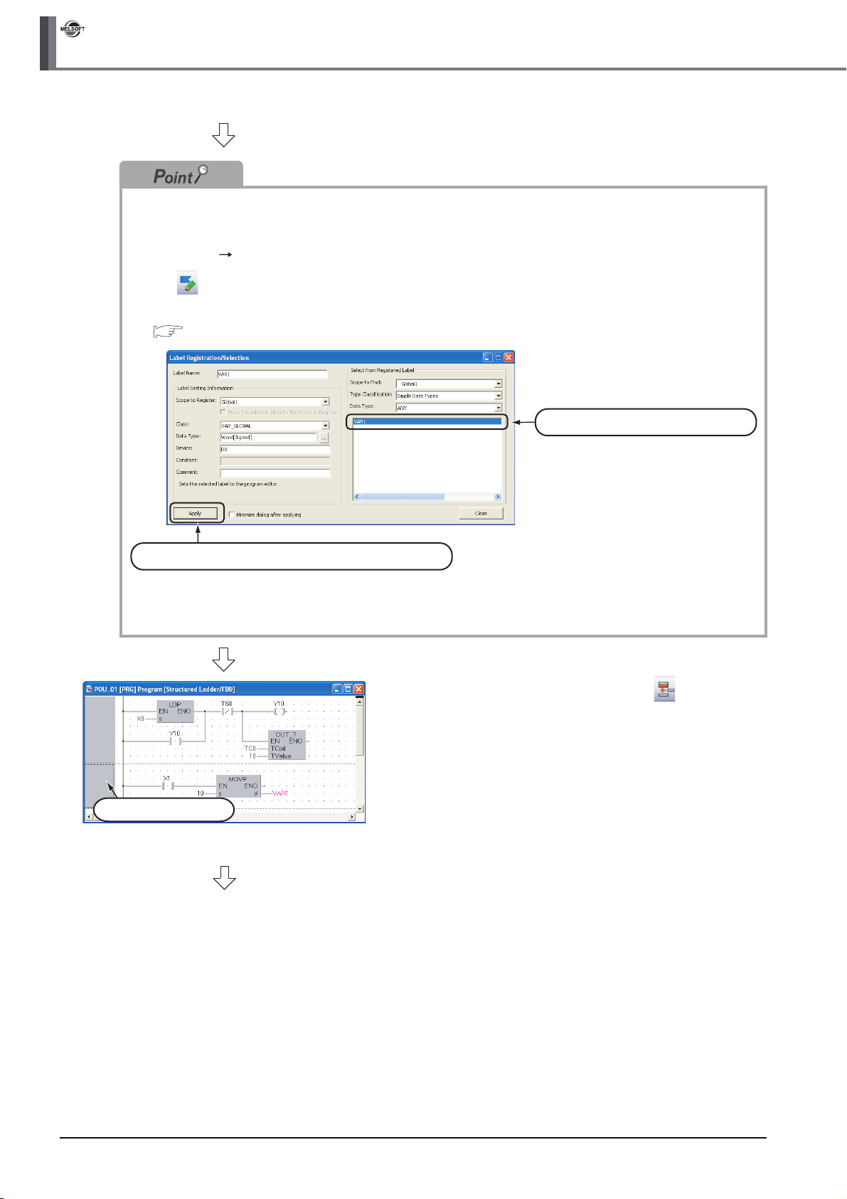
Selecting a label from the Label Registration/Selection screen
You can input a label also by selecting it from the Label Registration/Selection screen.
Perform the following procedure to display the Label Registration/Selection screen.
● Select "Edit" "List Operands".
● Click (List Operands).
Refer to the following manual for the details on the Label Registration/Selection screen:
GX Works2 Version 1 Operating Manual (Structured Project)
1) Select a label to be used.
2) Click the Apply button to set the selected.
Select a ladder block.
(To the next page)
15.Select a ladder block, and click (ADD
Ladder Block After) on the Structured Ladder/
FBD toolbar to add a ladder block.
3 - 16
3.2.6 Creating a program
Page 45

1)
Input variable "s" Output variable "d"
3.2 Creating a Project
16.Click (Open Contact) on the Structured
Ladder/FBD toolbar, and then move the cursor
to a desired position to display an open contact
there.
Click the open contact to connect it with the left bus
line and enable setting of a variable.
Settings
• Variable: X2
17.Select "Function" "MOVP" on the Function
Block Selection window, drag it, and drop it in a
desired position to position "MOVP" there.
Draw a grid line on the left figure (position 1) using
the procedure described in the step 3.
Click "?" of "s" and "d", and set the input and output
variables.
Settings
•s: 20
•d: VAR1
*1
1
OVERVIEW
2
CREATED PROGRAM
AND SYSTEM
CONFIGURATION
3
CREATING PROGRAM IN
STRUCTURED LADDER/
FBD LANGUAGE
4
(To the next page)
*1: The label VAR1 is set in Section 3.2.5.
CREATING
PROGRAM IN ST
LANGUAGE
5
CREATING TWO OR
MORE PROGRAM
BLOCKS
3.2.6 Creating a program
3 - 17
Page 46

GX Works2
3 CREATING PROGRAM IN STRUCTURED LADDER/FBD LANGUAGE
Copying a ladder block by drag & drop
When there is a similar ladder block, you can create a new ladder block efficiently by copying the existing
similar ladder block and editing necessary portions.
Drag an existing ladder block, and drop it while pressing the key to copy the existing ladder block.
Drag it, and drop it while pressing .
Change "X1" to "X2" in this example.
Change "10" to "20" in this example.
Changing over the device display format
You can check a program by changing over the device display format between "Device" and "Address".
Switch the device display format after performing compiling or compiling all when using local labels.
Refer to the following section for compiling:
3.2.7 Compiling a program
● Procedure to display Device
Select [View] [View Mode] [Device].
● Procedure to display Address
Select [View] [View Mode] [Address].
< Device mode> < Address mode >
Displaying labels and devices at the same time
You can display devices also in the label display mode by adding an optional setting.
Select [Tool] [Options] to display the Options screen.
On the Options screen, select "Program Editor" "Structured Ladder/FBD " "Label", and check "Display
label and devices".
In the example below, "X1" and " D0" are labels.
< Display Label mode > < Display label and devices mode >
3 - 18
3.2.6 Creating a program
Page 47

3.2 Creating a Project
3.2.7 Compiling a program
There are two types of compiling shown below. The compile target is different between the two types.
Select "Rebuild All" here.
The "Rebuild All" procedure is described below.
Refer to the following manual for compiling:
GX Works2 Version 1 Operating Manual (Structured Project)
Table 3.1 Compiling type and target program
Target program to be compiled
Build
Rebuild All
Converts non-compiled program blocks among program blocks registered in the task into
sequence program. (Does not compile already compiled program blocks.)
Converts all program blocks registered in the task into sequence program.
(Compiles already compiled program blocks also.)
1. Select [Compile] [Rebuild All] to execute
"Rebuild All".
You can click (Rebuild All) to execute "Rebuild
All".
1
OVERVIEW
2
CREATED PROGRAM
AND SYSTEM
CONFIGURATION
3
CREATING PROGRAM IN
STRUCTURED LADDER/
FBD LANGUAGE
2. The screen shown on the left appears.
Click the button to execute "Rebuild All".
If an error is detected, the Output window is
displayed.
• Make sure to compile the created or edited program to make it a sequence program executable in the
programmable controller CPU.
• "Warning C9062" is compiled correctly as a program, and can be monitored.
• Compile status checking method
You can check the compile status on the Project view.
4
CREATING
PROGRAM IN ST
LANGUAGE
5
CREATING TWO OR
MORE PROGRAM
BLOCKS
Each non-compiled portion is displayed in red.
3.2.7 Compiling a program
3 - 19
Page 48

GX Works2
3 CREATING PROGRAM IN STRUCTURED LADDER/FBD LANGUAGE
3.2.8 Creating an FBD program
Create an FBD program using the same procedure for Structured Ladder programs without using left
power rail on the left for Structured Ladder.
Display or hide left power rail by selecting [Edit] on the menu bar, selecting [Ladder Symbol], and
clicking [Left Power Rail].
Or hide Left Power Rail by clicking on the Structured Ladder/FBD tool bar.
Refer to 3.1.2 for an FBD program.
Displaying or hiding left power rail
● Even while left power rail are displayed, you can create an FBD program by ignoring left power rail.
● If you try to delete a left power rail to which a function, etc. is already connected, the left power rail is not
deleted.
Delete a connection to the left power rail first, and then delete the left power rail.
● It is not possible to create programs in the symbolic expression using FBD.
When using FBD, create programs in the functional expression using functions and operators.
Creating two or more ladders in one ladder block
When creating an FBD program, you can create two or more ladders in one ladder block. In this case, a
warning is displayed during compiling.
It is possible to hide this warning by adding an optional setting.
Select [Tool] [Options] to display the Options screen.
On the Options screen, select "Compile" "Output Result" "Disable Warning Codes", enter "C2034",
and click the
button button.
3 - 20
3.2.8 Creating an FBD program
Page 49

3.3 Writing a Project to the programmable controller
3.3 Writing a Project to the programmable controller
Write a project to the programmable controller CPU.
1
3.3.1 Connecting the personal computer to the programmable
controller
Connect the personal computer and a programmable controller with a cable, and set the connection
channel.
■ Connecting the personal computer to the programmable controller
Make sure to turn OFF the power of all units before connecting the personal computer to the
programmable controller CPU.
Refer to the following manual for the details on setting when using another channel or using the FXCPU
for connection.
Notebook personal computer
USB Cable
■ Setting the Transfer Setup
Programmable controller
(Q02HCPU)
OVERVIEW
2
CREATED PROGRAM
AND SYSTEM
CONFIGURATION
3
CREATING PROGRAM IN
STRUCTURED LADDER/
FBD LANGUAGE
4
CREATING
PROGRAM IN ST
LANGUAGE
Set the channel to connect the personal computer to the programmable controller CPU (Q02HCPU)
with a USB cable.
Refer to the following manual for the details on setting when using another channel or using the FX
CPU for connection.
GX Works2 Version 1 Operating Manual (Common)
1. Click "Connection Destination" in the view
selection area on the Navigation window to
display the Connection Destination view.
Click it.
2. Double-click "Connection1" in the Current
Connection on the Connection Destination view
to display the Transfer Setup screen.
Double-click it.
5
CREATING TWO OR
MORE PROGRAM
BLOCKS
(To the next page)
3.3.1 Connecting the personal computer to the programmable controller
3 - 21
Page 50

GX Works2
3 CREATING PROGRAM IN STRUCTURED LADDER/FBD LANGUAGE
3. Double-click (Serial USB) in "PC side I/F" to
display the PC side I/F Serial setting screen.
Double-click it.
Click it.
4. Set the PC side I/F.
After the setting, click the button to
complete the setting and close the screen.
Settings
• Select "USB".
5. Click (PLC Module) in "PLC side I/F" to
select the interface to be used.
3 - 22
(To the next page)
3.3.1 Connecting the personal computer to the programmable controller
Page 51

Click it.
3.3 Writing a Project to the programmable controller
6. Click the button to execute
a communication test with the programmable
controller through the specified connection
channel.
1
OVERVIEW
2
CREATED PROGRAM
AND SYSTEM
CONFIGURATION
3
7. When communication with the programmable
controller is finished normally, the left screen
appears, and the "PLC Type" field screen the
programmable controller CPU model name.
Click the button to close the screen.
If communication with the programmable controller
has failed, the screen below appears.
Check the connection destination, connection cable,
etc.
8. Click the button to finish "Transfer
Setup" and close the screen.
CREATING PROGRAM IN
STRUCTURED LADDER/
FBD LANGUAGE
4
CREATING
PROGRAM IN ST
LANGUAGE
5
CREATING TWO OR
MORE PROGRAM
BLOCKS
3.3.1 Connecting the personal computer to the programmable controller
3 - 23
Page 52

GX Works2
3 CREATING PROGRAM IN STRUCTURED LADDER/FBD LANGUAGE
● You can set two or more connection destinations and change them over if there are two or more
connection destinations.
1. Select "Connection1" in the Current
Connection on the Connection
Destination view, right-click it, and then
select the menu item "Add New Data".
The Add New Data screen will appear.
2. Set "Data Name", and uncheck "Set as
Default Connection".
Click the button to display the
newly created connection destination in
"All Connections" on the Connection
Destination view.
Settings
• Data Name : Connection2
• Set as Default Connection: Unchecked
3. Set the connection destination.
Double-click "Connection2" in "All
Connections" to display the Transfer
Setup screen.
3.3.1 Step3 in the Setting the
Transfer Setup
3 - 24
Newly created connection destination
3.3.1 Connecting the personal computer to the programmable controller
Page 53

3.3 Writing a Project to the programmable controller
● For selecting the newly created connection destination, check "Set as Default Connection " while creating
the data, or set the newly created connection destination as the default connection destination as described
below.
Then, the newly created connection destination will be selected as the connection destination for
communication with the programmable controller CPU (for "Read from PLC", "Write to PLC", etc).
1. Select "Connection2" in the All
Connections on the Connection
Destination view, right-click it, and then
select the menu item "Set as Default
Connection".
1
OVERVIEW
2
CREATED PROGRAM
AND SYSTEM
CONFIGURATION
3
Default Connection
2. The connection destination set as the
default connection destination is
displayed in "Current Connection" on the
Connection Destination view.
CREATING PROGRAM IN
STRUCTURED LADDER/
FBD LANGUAGE
4
CREATING
PROGRAM IN ST
LANGUAGE
5
CREATING TWO OR
MORE PROGRAM
BLOCKS
3.3.1 Connecting the personal computer to the programmable controller
3 - 25
Page 54

GX Works2
3 CREATING PROGRAM IN STRUCTURED LADDER/FBD LANGUAGE
3.3.2 Writing a project to the programmable controller
Write the project data to the programmable controller CPU set as the connection destination in Section
3.3.1.
1. Select "Online" "Write to PLC" to display the
Online Data Operation screen.
You can click (Write to PLC) to display the Online
Data Operation screen.
2. Set the "Target module" and "Target project" on
the Online Data Operation screen.
Setting of the target module
Click it.
Setting of the project
Setting of the target module
• Target module: Select <<PLC Module>>
Setting of the project
• Symbolic Information : Select "Program Memory/Device Memory" in "Target Memory", and
check "Symbolic Information" in "Target".
"Program (Program File)" and "MAIN" are checked in "PLC Data", and
change into gray.
"Symbolic Information" contains program files and variables.
• PLC Data : Select "Program Memory/Device Memory" in "Target Memory", and
check "PLC/Network/Remote Password/Switch Setting" in "Target". Do
not check "Global Device Comment" or "Device Memory".
After the setting, click the button.
3 - 26
(To the next page)
3.3.2 Writing a project to the programmable controller
Page 55

3.3 Writing a Project to the programmable controller
Restrictions
In the case of FXCPU
• The symbolic information is displayed only in the FX
• In the case of structured project, data can be read from the FXCPU only in the FX
3.00 or later.
When data cannot be read from the FXCPU, carefully store projects written in the programmable controller.
3U and FX3UC Series version 3.00 or later.
3U and FX3UC Series version
3. The left screen is displayed.
Click the button to write
the project (program).
If a program or parameters already exist in the programmable controller, the following screen appears.
Click the or button to overwrite the existing program or parameters.
When you click the button, GX Works2 overwrite the existing program or parameters without
displaying the overwrites confirmation screen for other data.
1
OVERVIEW
2
CREATED PROGRAM
AND SYSTEM
CONFIGURATION
3
CREATING PROGRAM IN
STRUCTURED LADDER/
FBD LANGUAGE
4
When parameters already exist When a program already exists
4. The left screen is displayed during
writing.
When writing is finished, "Write to
PLC: Completed" appears.
Click the button to close the
Write to PLC screen.
Writing Completed
CREATING
PROGRAM IN ST
LANGUAGE
5
CREATING TWO OR
MORE PROGRAM
BLOCKS
(To the next page)
3.3.2 Writing a project to the programmable controller
3 - 27
Page 56

GX Works2
3 CREATING PROGRAM IN STRUCTURED LADDER/FBD LANGUAGE
5. Click the button to close the
Online Data Operation screen.
3 - 28
3.3.2 Writing a project to the programmable controller
Page 57

3.4 Monitoring Operations
3.4 Monitoring Operations
Execute "Monitor" to check the operations.
In some monitor screen display examples, colors are changed for the convenience of printing.
GX Works2 has the function to simulate programmable controller operations in the offline mode.
Refer to the following manual for the simulation function:
GX Works2 Version 1 Operating Manual (Common)
3.4.1 Monitoring a program
1
OVERVIEW
2
Double-click it.
Click it.
1. Click "Project" in the view selection area on the
Navigation window to display the Project view.
2. Double-click "POU" "Program"
"POU_01" "Program" on the Project view to
display the POU_01 [PRG] Program [Structured
Ladder/FBD] screen.
CREATED PROGRAM
AND SYSTEM
CONFIGURATION
3
CREATING PROGRAM IN
STRUCTURED LADDER/
FBD LANGUAGE
4
CREATING
PROGRAM IN ST
LANGUAGE
5
CREATING TWO OR
MORE PROGRAM
BLOCKS
(To the next page)
3. Select [Online] [Monitor] [Start
Monitoring] to switch the POU_01 [PRG]
Program [Structured Ladder/FBD] screen to the
monitoring status.
You can also click (Start Monitoring) to switch
the POU_01 [PRG] Program [Structured Ladder/
FBD] screen to the monitoring status.
4. Set the programmable controller CPU to RUN.
Set the RUN/STOP switch on the
programmable controller CPU to "RUN".
3.4.1 Monitoring a program
3 - 29
Page 58
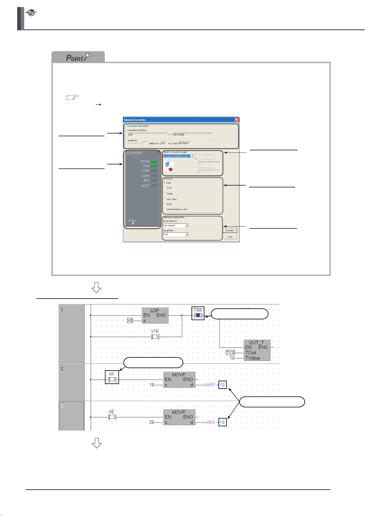
GX Works2
3 CREATING PROGRAM IN STRUCTURED LADDER/FBD LANGUAGE
You can switch the programmable controller status between "RUN" and "STOP" using remote operation as
follows.
The Settings of the remote operation may vary depending on the programmable controller used.
Refer to the following manual for the details on the remote operation:
GX Works2 Version 1 Operating Manual (Common)
Select [Online] [Remote Operation] to display the Remote Operation screen. You can switch the
programmable controller status between "RUN" and "STOP" on this screen.
Connection Channel
List information
Displays the connection
target information
currently set.
Programmable
controller status
Displays the programmable
controller CPU status.
Specify Execution
Target
Allows you to set the
target station for
remote operation.
Select "Currently
Specified Station" for
this example.
Operation
Allows you to select the
programmable controller
CPU status to be set.
Select either "RUN",
"PAUSE" or "STOP" for
this example.
Operation during RUN
Allows you to set the
operations to be
executed to the device
memory and signal
flow when the
programmable
controller CPU is
switched to RUN.
Monitor status display example
(To the next page)
Displays the ON status.
Displays the OFF status.
Displays the current values.
3 - 30
3.4.1 Monitoring a program
Page 59

3.4 Monitoring Operations
Monitor status
GX Works2 displays the Monitor status while it is executing the work window monitor.
The Monitor status disappears when GX Works2 stops all types of monitoring.
The Monitor status indicates the programmable controller CPU, simulator scan time, RUN/STOP status, etc.
Scan status
Select the Local Device monitor
USER status
ERR. status
RUN/STOP status
Connection status
Refer to the following manual for the Monitor status:
GX Works2 Version 1 Operating Manual (Common)
Monitor status display
● Display of bit value status (ON/OFF status)
GX Works2 displays the ON/OFF status (bit values) of contacts, coils, etc. as the ON/OFF status of devices and
labels.
Refer to the following manual for the bit value ON/OFF status display:
GX Works2 Version 1 Operating Manual (Common)
OFF status ON status
1
OVERVIEW
2
CREATED PROGRAM
AND SYSTEM
CONFIGURATION
3
CREATING PROGRAM IN
STRUCTURED LADDER/
FBD LANGUAGE
4
● Display of contents status (current value) other than bit values
GX Works2 displays the current values (of non -bit devices for) of contacts, coils, etc. and the contents of character
strings as shown below.
Current value of VAR1
● Switching of the current value display between decimal and hexadecimal
You can switch the current value display between decimal and hexadecimal using the following operations.
Operation to switch the current value display to decimal
Select [Online] [Monitor] [Change Value Format (Decimal)].
Operation to switch the current value display to hexadecimal
Select [Online] [Monitor] [Change Value Format (Hexadecimal)].
CREATING
PROGRAM IN ST
LANGUAGE
5
CREATING TWO OR
MORE PROGRAM
BLOCKS
3.4.1 Monitoring a program
3 - 31
Page 60

GX Works2
3 CREATING PROGRAM IN STRUCTURED LADDER/FBD LANGUAGE
Test operation
● Forcing a contact ON/OFF
Double-click a monitored device or label while pressing the key to force a device in the programmable
controller ON/OFF.
● Changing the current value of a word device
Double-click a monitored word device to display the Modify Value screen where you can change the current value.
Input the numeric value to be set, and
click the button to change the
current value to the input numeric value.
3 - 32
3.4.1 Monitoring a program
Page 61

3.4 Monitoring Operations
5. Turn ON inputs X0, X1 and X2 in the programmable controller, and check the following
operations.
You can turn ON inputs X0, X1 and X2 using the test operation above.
• When X0 turns ON, the programmable controller turns ON Y10, and then turns OFF Y10 1
second later.
X0 turns ON. Y10 remains ON for 1 second.
• When X1 turns ON, the programmable controller transfers K10 to VAR1 (device: D0).
X1 turns ON. The programmable controller transfers K10 to VAR1.
1
OVERVIEW
2
CREATED PROGRAM
AND SYSTEM
CONFIGURATION
3
• When X2 turns ON, the programmable controller transfers K20 to VAR1 (device: D0).
X2 turns ON. The programmable controller transfers K20 to VAR1.
6. Select [Online] [Monitor] [Stop
Monitoring] to reset the monitor status of the
POU_01 [PRG] Program [Structured Ladder/
FBD] screen.
You can click (Stop Monitoring) to reset the
monitor status of the POU_01 [PRG] Program
[Structured Ladder/FBD] screen.
7. Set the programmable controller CPU to STOP.
Set the RUN/STOP switch on the programmable
controller CPU to "STOP".
You can switch the programmable controller status
between "RUN" and "STOP" using remote
operation.
For the remote operation, refer to the following.
"Point" in the step4
CREATING PROGRAM IN
STRUCTURED LADDER/
FBD LANGUAGE
4
CREATING
PROGRAM IN ST
LANGUAGE
5
CREATING TWO OR
MORE PROGRAM
BLOCKS
3.4.1 Monitoring a program
3 - 33
Page 62
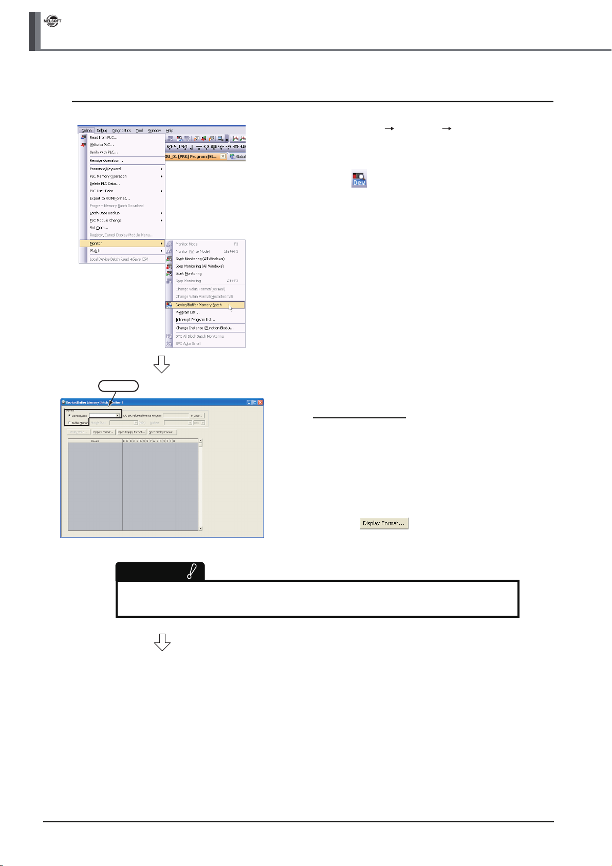
GX Works2
3 CREATING PROGRAM IN STRUCTURED LADDER/FBD LANGUAGE
3.4.2 Batch monitoring of device values
1. Select [Online] [Monitor] [Device/Buffer
Memory Batch] to display the Device/Buffer
Memory Batch Monitor screen.
Or click (Device/Buffer Memory Batch Monitor)
to display the Device/Buffer Memory Batch Monitor
screen.
Setting
Restrictions
Set a device/address to be monitored.
Label Name is not available.
(To the next page)
2. Set a device to be monitored.
Select D0 in this example.
Setting of "Device"
• Device : Select "Device Name".
• Device Name : D0
3. Click the button to display the
Display Format screen.
3 - 34
3.4.2 Batch monitoring of device values
Page 63

3.4 Monitoring Operations
4. Set the Display Format of the device to be
monitored.
Setting on the Display Format screen
• Monitor Format : Bit and Word
• Display : 16 bit Integer
•Value : DEC
• Bit Order : 0-F
• Switch No. of Points : Bit Device Bit and Word
Format 16 Points
After the setting, click the button to close
the Display Format screen.
Refer to the following manual for the details on
Display Format.
GX Works2 Version 1 Operating Manual
(Common)
1
OVERVIEW
2
CREATED PROGRAM
AND SYSTEM
CONFIGURATION
3
● You can save the contents set on the Display Format screen.
When the monitoring screen is opened again, the contents set previously on the Display Format
screen will not be displayed. (The default setting will be displayed.) To display the previous
setting, you can save the setting to a file, and read the file. To save the setting, click Save
Display Format on the Device/Buffer Memory Batch Monitor screen. To read the saved setting,
click Open Display Format on the Device/Buffer Memory Batch screen Monitor screen.
5. Click (Start Monitoring) on the toolbar to
start monitoring.
6. Set the programmable controller CPU to RUN.
Set the RUN/STOP switch on the programmable
controller CPU to "RUN".
CREATING PROGRAM IN
STRUCTURED LADDER/
FBD LANGUAGE
4
CREATING
PROGRAM IN ST
LANGUAGE
5
CREATING TWO OR
MORE PROGRAM
BLOCKS
(To the next page)
Current value
7. Click (Stop Monitoring) on the toolbar to
stop monitoring.
Monitored values remain even after GX Works2
stops monitoring.
3.4.2 Batch monitoring of device values
3 - 35
Page 64

GX Works2
3 CREATING PROGRAM IN STRUCTURED LADDER/FBD LANGUAGE
Click it.
8. Click on the screen to close the Device/
Buffer Memory Batch Monitor screen.
9. Set the programmable controller CPU to STOP.
Set the RUN/STOP switch on the programmable
controller CPU to "STOP".
You can switch the programmable controller status
between "RUN" and "STOP" using remote
operation.
For the remote operation, refer to the following.
"Point" in the 3.4.1
● Opening two or more Device/Buffer Memory Batch Monitor screens
You can open two or more Device/Buffer Memory Batch Monitor screens.
The screen number is indicated at the end of the screens title.
Number
● Changing the current value
Click the button on the Device/Buffer Memory Batch Monitor screen to display the Modify
Value screen which allows you to change the current value.
1. Select a device whose current
value is to be changed.
Selecting
(To the next page)
3 - 36
3.4.2 Batch monitoring of device values
Page 65

3.4 Monitoring Operations
1
Click it.
2. Click the button to
display the Modify Value screen.
Or click (Modify Value) to display
the Modify Value screen.
3. Change the current value.
For the change procedure, refer to the
following.
"Point" in the 3.4.1
OVERVIEW
2
CREATED PROGRAM
AND SYSTEM
CONFIGURATION
3
CREATING PROGRAM IN
STRUCTURED LADDER/
FBD LANGUAGE
4
CREATING
PROGRAM IN ST
LANGUAGE
5
CREATING TWO OR
MORE PROGRAM
BLOCKS
3.4.2 Batch monitoring of device values
3 - 37
Page 66

GX Works2
3 CREATING PROGRAM IN STRUCTURED LADDER/FBD LANGUAGE
3.5 Diagnosing the programmable controller
You can check the programmable controller RUN/STOP status and error status.
Refer to the following manual for the details on Network Diagnostics, Ethernet Diagnostics and CC-Link IE
Control Diagnostics.
GX Works2 Version 1 Operating Manual (Common)
1. Select [Diagnostics] [PLC Diagnostics] to
display the PLC Diagnostics screen.
13)
14)
15)
16)
No. Item Description
1) Connection Channel List
CPU information of
2)
connected station
Displayed information
3)
selection
4) Setting for Error Jump
5) Current Error Displays the current CPU error information.
6) Error History Displays the error history.
7) Error Jump
8) Error Clear Clears the error information displayed in "Current Error".
9) Error Help Displays the explanation window for the currently selected error number.
10) Error History Displays the latest error history.
11) Clear History Deletes the error history list in "Error History".
12) Status Icon Legend
13) Monitor Status Indicates the monitoring status (executed or stopped).
Programmable controller
14)
CPU information
15) Stop Monitor Starts or stops monitoring.
16) Create CSV File Saves the error information to a CSV file.
6)
Connection Channel List:
Displays the information on connection between the personal computer and the programmable controller CPU.
System Image: Displays visually the Connection Channel List.
Displays the model name, operation status and switch status.
Select a radio button to display Error Information (Current Error and Error History)/PLC Status
Information/Serial Communication Error.
Check this check box to reduce the PLC Diagnostics screen size and adjust the display position at
the time of Error Jump.
Jumps to the ladder step number which contains the error corresponding to the currently selected
error number.
Indicates icons corresponding to errors displayed in the "Status" column of the "Error Information".
Displays the programmable controller CPU status.
1)
2)
3)
5)
4)
7)
8)
9)
10)
11)
7)
9)
12)
3 - 38
2. Click the button to close the PLC Diagnostics screen.
3.4.2 Batch monitoring of device values
Page 67

3.6 Reading a Project from programmable controller
3.6 Reading a Project from programmable controller
You can read data to a project from the programmable controller CPU selected as the connection destination
in Section 3.3.1.
1. Select [Online] [Read from PLC]
to display the Online Data Operation
screen.
You can click (Read from PLC) to
display the Online Data Operation
screen.
2. Set the "Target module" and "Target
project" on the Online Data
Operation screen.
Setting of the target module
After the setting, click the
button to read the project (program)
from the programmable controller.
1
OVERVIEW
2
CREATED PROGRAM
AND SYSTEM
CONFIGURATION
3
CREATING PROGRAM IN
STRUCTURED LADDER/
FBD LANGUAGE
4
Click it.
Setting of the project
Setting of the target module
• Target module: Select <<PLC Module>>.
Setting of the project
• Symbolic Information : Select "Program Memory/Device Memory" in "Target Memory", and
check "GX Works2 (Structured Project)" in "Target".
"Symbolic Information" contains program files and variables.
• PLC Data : Select "Program Memory/Device Memory" in "Target Memory", and
check "PLC/Network/Remote Password/Switch Setting" in "Target".
Do not check "Global Device Comment" and "Device Memory".
*1: If you have checked desired items for the Write to PLC setting, such items are checked as the
default for the Read from PLC setting.
(To the next page)
CREATING
PROGRAM IN ST
LANGUAGE
5
CREATING TWO OR
MORE PROGRAM
BLOCKS
*1
Restrictions
In the case of FXCPU
• In the case of structured project, data can be read from the FXCPU only in the FX
3.00 or later.
When data cannot be read from the FXCPU, carefully store projects written in the programmable controller.
3.4.2 Batch monitoring of device values
3U and FX3UC Series version
3 - 39
Page 68

GX Works2
3 CREATING PROGRAM IN STRUCTURED LADDER/FBD LANGUAGE
If a program or parameters already exist in the GX Works2, the following screen appears.
Click the or button to overwrite the existing program or parameters.
When you click the button, GX Works2 overwrite the existing program or parameters without
displaying the overwrites confirmation screen for other data.
When symbolic information already exists When parameters already exist
Reading Completed
3. The left screen is displayed during
reading.
When reading is finished, "Read from
PLC: Completed" appears.
Click the button to close the
Read from PLC screen.
4. Click the button to close the
Online Data Operation screen.
3 - 40
3.4.2 Batch monitoring of device values
Page 69

3.7 Printing
You can print programs and parameters created using GX Works2 in a printer.
The print function consists of Batch print and print. This section explains print.
For details of printing, refer to the following manual.
GX Works2 Version 1 Operating Manual (Common)
3.7.1 Setting the printer
The printer which prints is set up.
1. Select [Project] [Printer Setup] to display the
Printer Setup screen.
3.7 Printing
1
OVERVIEW
2
CREATED PROGRAM
AND SYSTEM
CONFIGURATION
3
2. Select the Printer, Paper size, Orientation, etc.
After the setting, click the button to close
the Printer Setup screen.
CREATING PROGRAM IN
STRUCTURED LADDER/
FBD LANGUAGE
4
CREATING
PROGRAM IN ST
LANGUAGE
5
CREATING TWO OR
MORE PROGRAM
BLOCKS
3.7.1 Setting the printer
3 - 41
Page 70

GX Works2
3 CREATING PROGRAM IN STRUCTURED LADDER/FBD LANGUAGE
3.7.2 Previewing a program
You can display a program in the image of printing.
1. Click "Project" in the view selection area on the
Navigation window to display the Project view.
Click it.
2. Double-click "POU" "Program"
"POU_01" "Program" on the Project view to
display the POU_01 [PRG] Program [Structured
Ladder/FBD] screen.
Double-click it.
(To the next page)
3 - 42
3.7.2 Previewing a program
Page 71

3.7 Printing
3. Select [Project] [Print Window Preview] to
display the Print Window Preview screen.
1
OVERVIEW
2
CREATED PROGRAM
AND SYSTEM
CONFIGURATION
3
4. After checking the contents, click the button to print the program.
Click the button to close the Print Window Preview screen.
Click button to print the program.
CREATING PROGRAM IN
STRUCTURED LADDER/
FBD LANGUAGE
4
CREATING
PROGRAM IN ST
LANGUAGE
5
CREATING TWO OR
MORE PROGRAM
BLOCKS
3.7.2 Previewing a program
3 - 43
Page 72

GX Works2
3 CREATING PROGRAM IN STRUCTURED LADDER/FBD LANGUAGE
3.7.3 Printing a program
1. Display a program.
For the display procedure, refer to the following.
3.7.2 Previewing a program
2. Select [Project] [Print Window] to display the
Print Window screen.
3 - 44
3. Click the button to start printing.
Click it.
3.7.3 Printing a program
Page 73

3.7.4 Previewing a PLC Parameter
You can display PLC Parameter in the image of printing.
1. Display PLC parameters.
Double-click "Parameter" "PLC Parameter" on
Double-click it.
the Project view to display the Q Parameter Setting
screen.
2. Click the button.
3.7 Printing
1
OVERVIEW
2
CREATED PROGRAM
AND SYSTEM
CONFIGURATION
3
CREATING PROGRAM IN
STRUCTURED LADDER/
FBD LANGUAGE
Click it.
Click button to print PLC
Parameter.
3. After checking the contents, click the
button to print PLC Parameter.
Click the button to close the Print Window
Preview screen.
4
CREATING
PROGRAM IN ST
LANGUAGE
5
CREATING TWO OR
MORE PROGRAM
BLOCKS
3.7.4 Previewing a PLC Parameter
3 - 45
Page 74

GX Works2
3 CREATING PROGRAM IN STRUCTURED LADDER/FBD LANGUAGE
3.7.5 Printing a PLC Parameter
1. Display a PLC Parameter.
For the display procedure, refer to the following.
3.7.4 Previewing a PLC Parameter
2. Click the button.
Click it.
Click it.
3. Click the button to start printing.
3 - 46
3.7.5 Printing a PLC Parameter
Page 75

3.8 Saving a Project
t
You can save a project.
When saving a newly created project, use the menu item [Save as].
1. Select [Project] [Save As] to display the
Save As screen.
2. Set the "Save Location", "Workspace Name",
"Project Name", "Title", etc.
After the setting, click the button to save the
project (program).
Refer to the following manual for the details:
GX Works2 Version 1 Operating Manual
(Common)
Settings
• Save Location : Specify the save destination
• Workspace Name : Specify the save destination
• Project Name : Specify the project name.
• Title : Specify the title.
3.8 Saving a Project
folder.
folder name.
You can save a project withou
specifying a title.
1
OVERVIEW
2
CREATED PROGRAM
AND SYSTEM
CONFIGURATION
3
CREATING PROGRAM IN
STRUCTURED LADDER/
FBD LANGUAGE
4
CREATING
PROGRAM IN ST
LANGUAGE
5
Restrictions
● Input within 128 characters to "Title".
● Make sure that the total characters of "Save Folder Path", "Workspace Name" and "Project Name" is 200
or less.
● You cannot save any project to route directories such as "C:\" or "D:\".
3. Click the button to save the new project.
CREATING TWO OR
MORE PROGRAM
BLOCKS
3.7.5 Printing a PLC Parameter
3 - 47
Page 76
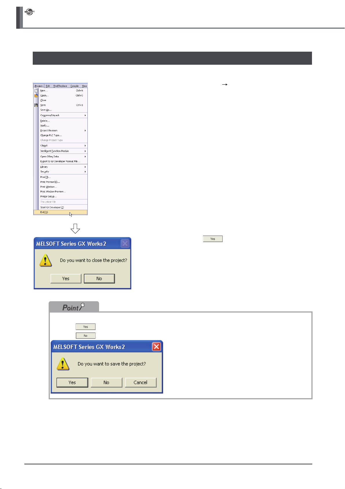
GX Works2
3 CREATING PROGRAM IN STRUCTURED LADDER/FBD LANGUAGE
3.9 Exiting GX Works2
End the project.
1. Select [Project] [Exit (Q)].
2. Click the button to exit GX Works2.
If you have not saved the project, the following message appears.
Click the button to save the project.
Click the button to exit GX Works2 without saving the project.
3 - 48
3.7.5 Printing a PLC Parameter
Page 77
1
OVERVIEW
4 CREATING PROGRAM IN
ST LANGUAGE
This chapter explains how to create a program in the ST language with a Structured Project using a simple ST
program.
Refer to the following manuals for the details on structured programs including programming languages,
labels, data types and functions (instructions):
MELSEC-Q/L/F Structured Programming Manual (Fundamentals)
Structured Programming Manual of the programmable controller CPU
4.1 Created Program . . . . . . . . . . . . . . . . . . . . . . . . . . . . . . . . . . . . . 4-2
4.2 Creating a Project . . . . . . . . . . . . . . . . . . . . . . . . . . . . . . . . . . . . 4-3
4.3 Writing a Project to the programmable controller . . . . . . . . . . 4-7
4.4 Monitoring Operations . . . . . . . . . . . . . . . . . . . . . . . . . . . . . . . . 4-7
4.5 Diagnosing the programmable controller. . . . . . . . . . . . . . . . 4-11
4.6 Reading a Project from programmable controller . . . . . . . . . 4-11
4.7 Printing. . . . . . . . . . . . . . . . . . . . . . . . . . . . . . . . . . . . . . . . . . . . 4-11
4.8 Saving a Project . . . . . . . . . . . . . . . . . . . . . . . . . . . . . . . . . . . . 4-11
4.9 Exiting GX Works2 . . . . . . . . . . . . . . . . . . . . . . . . . . . . . . . . . . 4-11
2
CREATED PROGRAM
AND SYSTEM
CONFIGURATION
3
CREATING PROGRAM IN
STRUCTURED LADDER/
FBD LANGUAGE
4
CREATING
PROGRAM IN ST
LANGUAGE
5
CREATING TWO OR
MORE PROGRAM
BLOCKS
4 - 1
Page 78
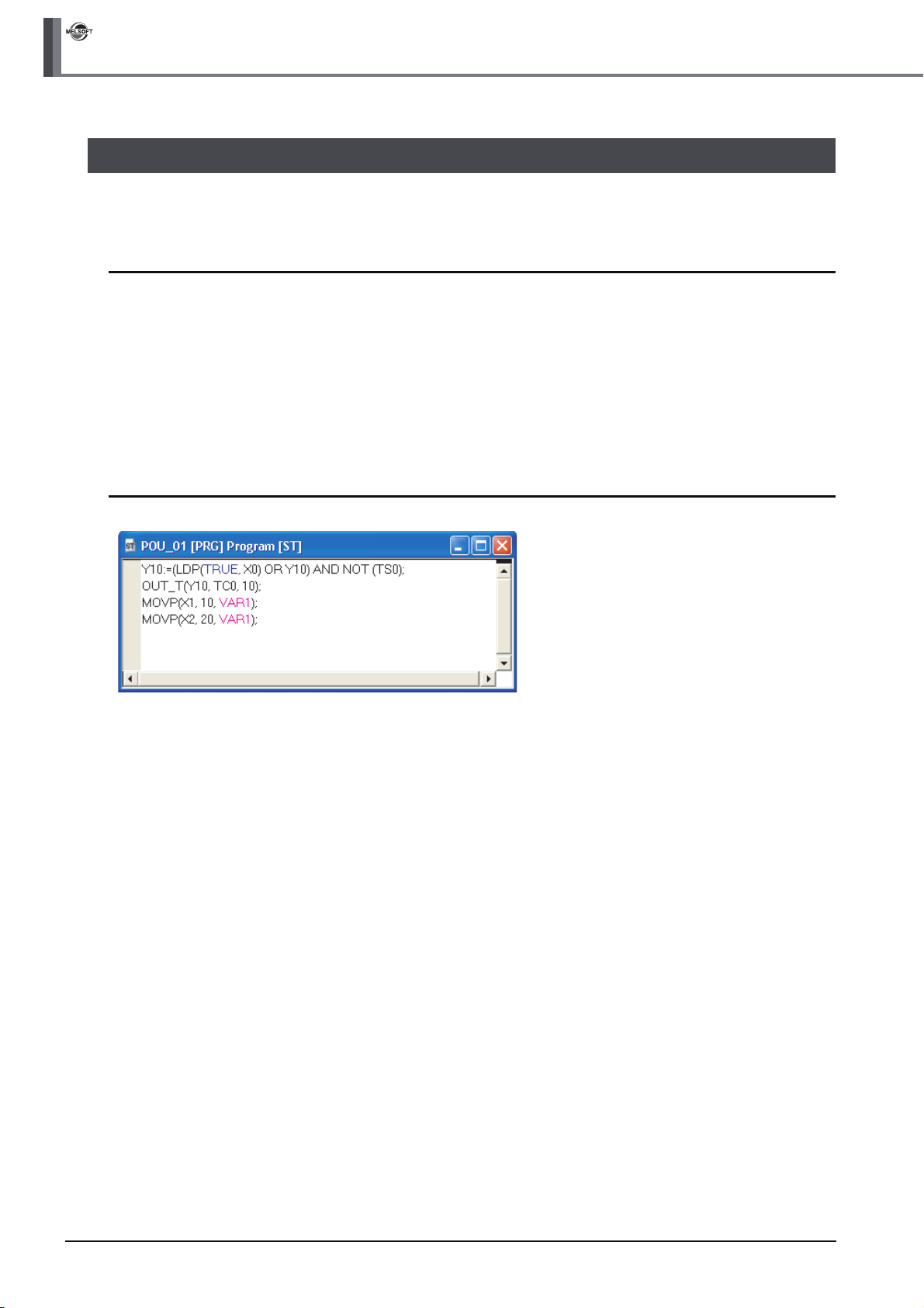
GX Works2
4 CREATING PROGRAM IN ST LANGUAGE
4.1 Created Program
This section explains the operations of the program to be created and ST programs.
4.1.1 Operations of program
● When X0 turns ON, the programmable controller turns ON Y10, and then turns OFF Y10 1 second
later.
● When X1 turns ON, the programmable controller transfers K10 to D0 (which is defined with the
LABEL "VAR1").
● When X2 turns ON, the programmable controller transfers K20 to D0 (which is defined with the
LABEL "VAR1").
4.1.2 Created program
4 - 2
4.1.1 Operations of program
Page 79
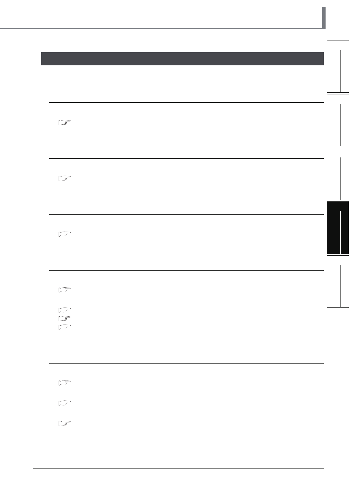
4.2 Creating a Project
Create a project using ST program.
4.2.1 Starting GX Works2
Refer to the following section for the GX Works2 startup procedure:
3.2.1 Starting GX Works2
4.2 Creating a Project
1
OVERVIEW
2
CREATED PROGRAM
AND SYSTEM
CONFIGURATION
4.2.2 Screen configuration in GX Works2
Refer to the following section for the GX Works2 screen configuration:
3.2.2 Screen configuration in GX Works2
4.2.3 Creating a new project
Refer to the following section for the new project creation procedure:
3.2.3 Creating a new project
4.2.4 Setting parameters
Refer to the following section for the parameter setting procedure:
3.2.4 Setting parameters
Refer to the following manuals for the details on parameter setting:
GX Works2 Version 1 Operating Manual (Common)
CPU Manual
CPU Programming manual
3
CREATING PROGRAM IN
STRUCTURED LADDER/
FBD LANGUAGE
4
CREATING
PROGRAM IN ST
LANGUAGE
5
CREATING TWO OR
MORE PROGRAM
BLOCKS
4.2.5 Setting labels
Refer to the following section for the global label setting procedures:
3.2.5 Setting labels
Refer to the following manual for the details on global/local label setting procedures:
GX Works2 Version 1 Operating Manual (Structured Project)
Refer to the following manual for the details on programming of global labels and local labels:
MELSEC-Q/L/F Structured Programming Manual (Fundamentals)
4.2.1 Starting GX Works2
4 - 3
Page 80

GX Works2
4 CREATING PROGRAM IN ST LANGUAGE
4.2.6 Creating a program
Create the ST program shown in Section 4.1.2.
1. Double-click "POU" "Program" "POU_01"
Double-click it.
"Program" on the Project view to display the
POU_01 [PRG] Program [ST] screen.
2. Input "Y10:=(LDP(TRUE
NOT (TS0
*2
);" directly, and click the key.
*1
, X0) OR Y10) AND
You can use the Function Block Selection window
for the input.
Settings
•Y10:= (LDP(TRUE*1, X0) OR Y10) AND NOT
*2
(TS0
);
*1: "TRUE" indicates the ON status.
*2: "TS0" indicates the contact of timer T0.
(To the next page)
Basic description and display colors
Programming in the ST language consists of syntaxes, operators, function, function block, devices, labels, etc.
Refer to the following manual for syntaxes, operators and programming:
MELSEC-Q/L/F Structured Programming Manual (Fundamentals)
● Make sure to write ";" at the end of a statement.
● Comment
You can describe comments in a program.
4 - 4
You can describe
comments
within program.
4.2.6 Creating a program
Make sure to enter a ";" at
the end of each statement.
Page 81

4.2 Creating a Project
● Display colors
GX Works2 displays syntax, operators, comments, constants, string constants, devices and labels using the
following colors (in the initial setting).
• Syntax: ( )
• Operator: ( )
• Comment: ( )
• Constant: ( )
• String constant: ( )
• Device: ( )
• Global label: ( )
• Local label: ( )
Input using the FB Selection window
You can easily input the function name of a Function or Function block by dragging it to the cursor position from
the Function Block Selection window.
In the example below, drag the function "LDP" from the Function Block Selection window, and drop it on the
POU_01 [PRG] Program [ST] screen to input it there. After that, input the parameters of the function.
Refer to the following manual for the details:
blue
black
dark green
black
black
black
magenta
magenta
GX Works2 Version 1 Operating Manual (Structured Project)
1
OVERVIEW
2
CREATED PROGRAM
AND SYSTEM
CONFIGURATION
3
2) Drop it.
1) Drag it.
3. Input "OUT_T(Y10,TC0
*1
,10);" directly, and
click the key.
You can select "Function" "OUT_T" on the
Function Block Selection window.
Settings
• OUT_T(Y10,TC0*1,10);
*1: "TC0" indicates the coil of timer T0.
CREATING PROGRAM IN
STRUCTURED LADDER/
FBD LANGUAGE
4
CREATING
PROGRAM IN ST
LANGUAGE
5
CREATING TWO OR
MORE PROGRAM
BLOCKS
(To the next page)
4. Input "MOVP(X1,10,VAR1
*2
);" directly, and click
the key.
You can select "Function" "MOVP" on the
Function Block Selection window.
Settings
• MOVP(X1,10,VAR1*2);
*2: The label VAR1 is set in Section 4.2.5.
4.2.6 Creating a program
4 - 5
Page 82

GX Works2
4 CREATING PROGRAM IN ST LANGUAGE
Selecting a label from the Label Registration/Selection screen
You can input a label also by selecting it from the Label Registration/Selection screen.
Perform the following procedure to display the Label Registration/Selection screen.
● Select "Edit" "List Operands".
● Click (List Operands).
Refer to the following manual for the details on the Label Registration/Selection screen:
GX Works2 Version 1 Operating Manual (Structured Project)
Select a label to be used.
Click the Apply button to set the selected label.
Using templates
Using templates according to the instructions/functions.
4.2.7 Compiling a program
5. Input "MOVP(X2,20,VAR1
*1
)" directly .
You can select "Function" "MOVP" on the
Function Block Selection window.
Settings
• MOVP(X2,20,VAR1*1)
*1: The label VAR1 is set in Section 4.2.5.
4 - 6
Refer to the following section and manual for compiling:
3.2.7 Compiling a program
GX Works2 Version 1 Operating Manual (Structured Project)
4.2.7 Compiling a program
Page 83

4.3 Writing a Project to the programmable controller
4.3 Writing a Project to the programmable controller
Refer to the following section for the procedure to write a project to the programmable controller CPU.
3.3 Writing a Project to the programmable controller
4.4 Monitoring Operations
Execute "Monitor" to check the operations.
Note that some screen shot colors have been changed for printing convenience.
GX Works2 is able to simulate the programmable controller operations in offline mode.
Refer to the following manual for the simulation function:
GX Works2 Version 1 Operating Manual (Common)
4.4.1 Monitoring a program
1. Click "Project" in the view selection area on the
Navigation window to display the Project view.
1
OVERVIEW
2
CREATED PROGRAM
AND SYSTEM
CONFIGURATION
3
CREATING PROGRAM IN
STRUCTURED LADDER/
FBD LANGUAGE
Double-click it.
Click it.
2. Double-click "POU" "Program"
"POU_01" "Program" on the Project view to
display the POU_01 [PRG] Program [ST]
screen.
3. Select [Online] [Monitor] [Start
Monitoring] to switch the
POU_01[PRG]Program[ST] screen to the
monitoring status.
You can also click (Start Monitoring) to switch
the POU_01[PRG]Program[ST] screen to the
monitoring status.
4
CREATING
PROGRAM IN ST
LANGUAGE
5
CREATING TWO OR
MORE PROGRAM
BLOCKS
(To the next page)
4. Set the programmable controller CPU to RUN.
Set the RUN/STOP switch on the programmable
controller CPU to "RUN".
4.4.1 Monitoring a program
4 - 7
Page 84

GX Works2
4 CREATING PROGRAM IN ST LANGUAGE
You can switch the programmable controller status between "RUN" and "STOP" using remote operation as
follows.
The Settings of the remote operation may vary depending on the programmable controller used.
Refer to the following manual for the details on the remote operation:
GX Works2 Version 1 Operating Manual (Common)
Select [Online] [Remote Operation] to display the Remote Operation screen. You can switch the
programmable controller status between "RUN" and "STOP" on this screen.
Connection Channel
List information
Displays the connection
target information
currently set.
Programmable
controller status
Displays the programmable
controller CPU status.
Specify Execution
Target
Allows you to set the
target station for
remote operation.
Select "Currently
Specified Station" for
this example.
Operation
Allows you to select the
programmable controller
CPU status to be set.
Select either "RUN",
"PAUSE" or "STOP" for
this example.
Operation during RUN
Allows you to set the
operations to be
executed to the device
memory and signal
flow when the
programmable
controller CPU is
switched to RUN.
Monitor status display example
Displays the ON status.
(To the next page)
Displays the OFF status.
Displays the current values.
4 - 8
4.4.1 Monitoring a program
Page 85

4.4 Monitoring Operations
Monitor status
GX Works2 displays the Monitor status while it is executing the work window monitor.
The Monitor status disappears when GX Works2 stops all types of monitoring.
The Monitor status indicates the programmable controller CPU, simulator scan time, RUN/STOP status, etc.
Scan status
Select the Local Device monitor
USER status
ERR. status
RUN/STOP status
Connection status
Refer to the following manual for the Monitor status:
GX Works2 Version 1 Operating Manual (Common)
Monitor status display
● Switching of the current value display between decimal and hexadecimal
You can switch the current value display between decimal and hexadecimal using the following procedure.
Procedure to switch the current value display to decimal:
Select [Online] [Monitor] [Change Value Format(Decimal)].
Procedure to switch the current value display to hexadecimal:
Select [Online] [Monitor] [Change Value Format(Hexadecimal)].
1
OVERVIEW
2
CREATED PROGRAM
AND SYSTEM
CONFIGURATION
3
CREATING PROGRAM IN
STRUCTURED LADDER/
FBD LANGUAGE
4
Refer to the next page for the test operation.
Test operation
● Forcing a contact ON/OFF
Double-click a monitored device or label while pressing the key to force a device in the programmable
controller ON/OFF.
● Changing the current value of a word device
Double-click a monitored word device to display the Modify Value screen where you can change the current value.
Input the numeric value to be set, and
click the button to change the
current value to the input numeric value.
CREATING
PROGRAM IN ST
LANGUAGE
5
CREATING TWO OR
MORE PROGRAM
BLOCKS
4.4.1 Monitoring a program
4 - 9
Page 86

GX Works2
4 CREATING PROGRAM IN ST LANGUAGE
5. Turn ON inputs X0, X1 and X2 in the programmable controller, and check the following
operations.
You can turn ON inputs X0, X1 and X2 using the test operation above.
• When X0 turns ON, the programmable controller turns ON Y10, and then turns OFF Y10 1
second later.
Y10 remains ON
for 1 second.
• When X1 turns ON, the programmable controller transfers K10 to VAR1 (device: D0).
X1 turns ON.
• When X2 turns ON, the programmable controller transfers K20 to VAR1 (device: D0).
X2 turns ON.
X0 turns ON.
VAR1 becomes "10".
VAR1 becomes "20".
6. Select [Online] [Monitor] [Stop
Monitoring] to stop (pause) the monitor status
on the POU_01 [PRG] Program [ST] screen.
You can click (Stop Monitoring) to reset the
POU_01 [PRG] Program [ST] screen.
7. Set the programmable controller CPU to STOP.
4.4.2 Batch monitoring of device values
For the Batch monitoring of device values procedure, refer to the following.
3.4.2 Batch monitoring of device values
4 - 10
4.4.2 Batch monitoring of device values
Set the RUN/STOP switch on the programmable
controller CPU to "STOP".
You can switch the programmable controller status
between "RUN" and "STOP" using remote
operation.
"Point" in the step4
Page 87

4.5 Diagnosing the programmable controller
4.5 Diagnosing the programmable controller
You can check the programmable controller RUN/STOP status and error status.
Refer to the following section for the diagnosis procedure:
3.5 Diagnosing the programmable controller
4.6 Reading a Project from programmable controller
Refer to the following section for the procedure to read a project from the programmable controller:
3.6 Reading a Project from programmable controller
4.7 Printing
For the Saving a Project procedure, refer to the following.
3.7 Printing
1
OVERVIEW
2
CREATED PROGRAM
AND SYSTEM
CONFIGURATION
3
4.8 Saving a Project
Refer to the following section for the project saving procedure:
3.8 Saving a Project
4.9 Exiting GX Works2
Refer to the following section for the project ending procedure:
3.9 Exiting GX Works2
CREATING PROGRAM IN
STRUCTURED LADDER/
FBD LANGUAGE
4
CREATING
PROGRAM IN ST
LANGUAGE
5
CREATING TWO OR
MORE PROGRAM
BLOCKS
4.4.2 Batch monitoring of device values
4 - 11
Page 88

GX Works2
4 CREATING PROGRAM IN ST LANGUAGE
MEMO
4 - 12
4.4.2 Batch monitoring of device values
Page 89
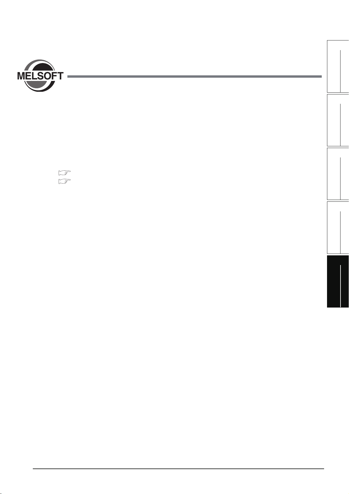
1
OVERVIEW
5 CREATING TWO OR MORE
PROGRAM BLOCKS
This chapter explains how to create a Structured Project in which two or more program blocks are made into
one program using a simple example.
Refer to the following manuals for the details on structured programs including programming languages,
labels, data types and functions (instructions):
MELSEC-Q/L/F Structured Programming Manual (Fundamentals)
Structured Programming Manual of the programmable controller CPU
5.1 Created Program . . . . . . . . . . . . . . . . . . . . . . . . . . . . . . . . . . . . . 5-2
5.2 Creating a Project . . . . . . . . . . . . . . . . . . . . . . . . . . . . . . . . . . . . 5-4
5.3 Writing a Project to the programmable controller . . . . . . . . . 5-12
5.4 Monitoring Operations . . . . . . . . . . . . . . . . . . . . . . . . . . . . . . . 5-12
5.5 Diagnosing the programmable controller. . . . . . . . . . . . . . . . 5-18
5.6 Reading a Project from programmable controller . . . . . . . . . 5-18
5.7 Printing. . . . . . . . . . . . . . . . . . . . . . . . . . . . . . . . . . . . . . . . . . . . 5-19
5.8 Saving a Project . . . . . . . . . . . . . . . . . . . . . . . . . . . . . . . . . . . . 5-19
5.9 Exiting GX Works2 . . . . . . . . . . . . . . . . . . . . . . . . . . . . . . . . . . 5-19
2
CREATED PROGRAM
AND SYSTEM
CONFIGURATION
3
CREATING PROGRAM IN
STRUCTURED LADDER/
FBD LANGUAGE
4
CREATING
PROGRAM IN ST
LANGUAGE
5
CREATING TWO OR
MORE PROGRAM
BLOCKS
5 - 1
Page 90

GX Works2
Y10
5 CREATING TWO OR MORE PROGRAM BLOCKS
5.1 Created Program
This section explains how to create a program for controlling a tea server system which consists of a tea
pouring operation, water refilling operation and warning indicating operation. This section also explains a
program which works as one Structured Project, and the program operations.
5.1.1 Operations of program
Tea leaf
Tea leaf
replacement
check button
replacement
indicator lamp
X2
Y12
Water refill output
Y11
Tea pouring
Tea pouring
output
Y10
Y10
Cup detection
button
X0
X1
check
pour
Upper limit switch
X4
Water refill tank
Lower limit switch
X3
■ Tea pouring operation
When a user presses the tea pouring button X1 (that is, when X1 turns ON) while the cup detection
X0 is ON, the tea pouring output Y10 turns ON and the tea server pours tea into the cup. The tea
server pours tea while the user is pressing and holding the button, and stops pouring when the user
releases the button.
The tea server does not pour tea when the user presses the tea pouring button X1 if the cup
detection X0 is OFF.
■ Water refilling operation
5 - 2
When water inside the water refill tank is running low, the lower limit switch X3 turns ON, and the
water refill output Y11 turns ON.
When the water refill output Y11 is ON and the water supply to the tank is sufficient, the upper limit
switch X4 turns ON and the water refill output Y11 turns OFF.
■ Warning indicating operation
• When the tea server performs the water refilling operation 5 times, the tea leaf replacement
indicator lamp Y12 turns ON.
• When a user presses the tea leaf replacement check button X2, the tea leaf replacement indicator
lamp Y12 turns OFF.
5.1.1 Operations of program
Page 91
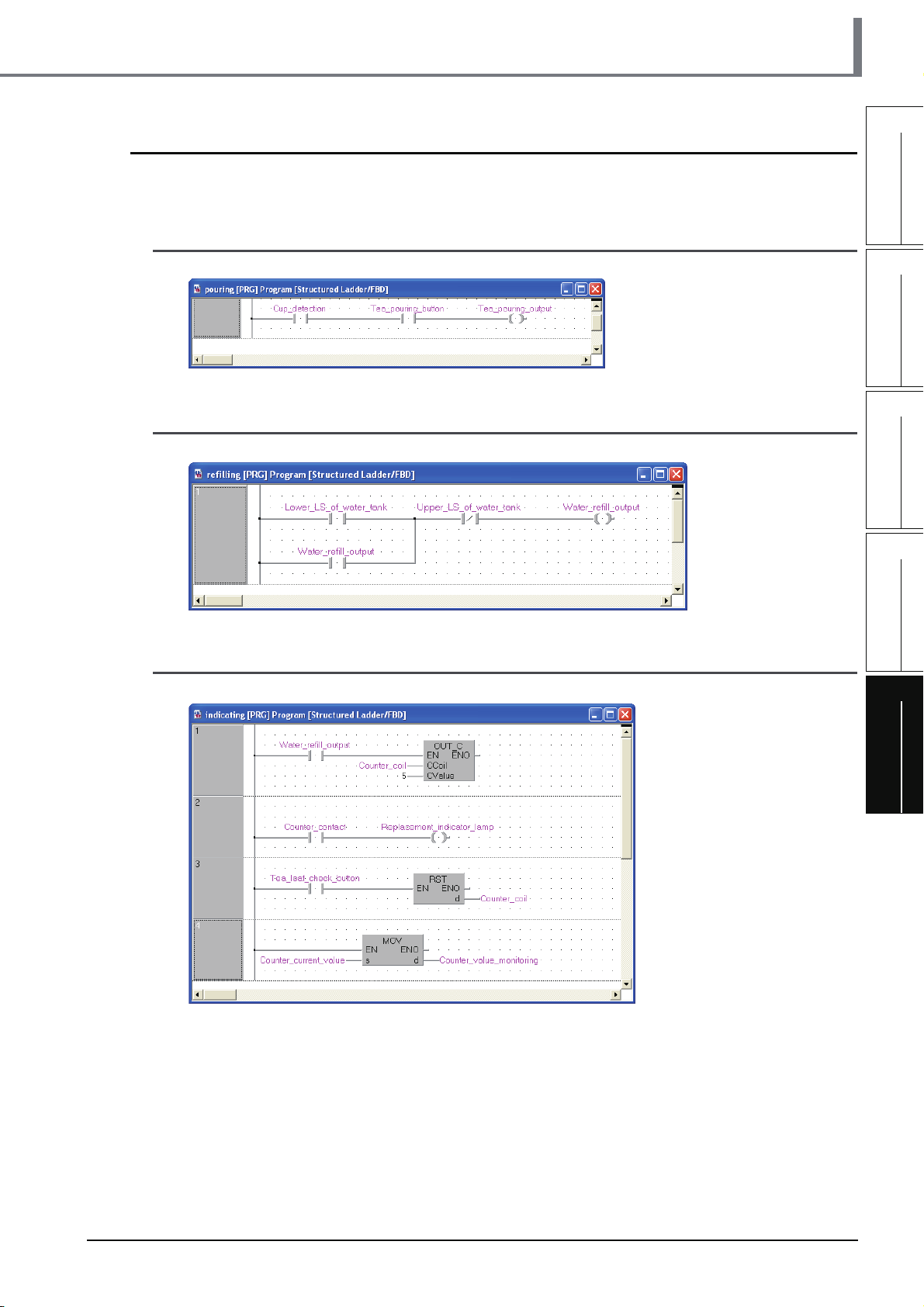
5.1.2 Created program
Create the following program blocks.
5.1 Created Program
1
■ Program block for the tea pouring operation
■ Program block for the water refilling operation
■ Program block for the warning indicating operation
OVERVIEW
2
CREATED PROGRAM
AND SYSTEM
CONFIGURATION
3
CREATING PROGRAM IN
STRUCTURED LADDER/
FBD LANGUAGE
4
CREATING
PROGRAM IN ST
LANGUAGE
5
CREATING TWO OR
MORE PROGRAM
BLOCKS
5.1.2 Created program
5 - 3
Page 92

GX Works2
5 CREATING TWO OR MORE PROGRAM BLOCKS
5.2 Creating a Project
Create projects for the tea pouring operation, water refilling operation and warning indicating operation using
Structured Ladder program.
5.2.1 Starting GX Works2
Refer to the following section for the GX Works2 startup procedure:
3.2.1 Starting GX Works2
5.2.2 Screen configuration in GX Works2
Refer to the following section for the GX Works2 screen configuration:
3.2.2 Screen configuration in GX Works2
5.2.3 Creating a new project
Refer to the following section for the new project creation procedure:
3.2.3 Creating a new project
5.2.4 Setting parameters
Refer to the following section for the parameter setting procedure:
3.2.4 Setting parameters
Refer to the following manuals for the details on parameter setting:
GX Works2 Version 1 Operating Manual (Common)
CPU Manual
CPU Programming manual
5 - 4
5.2.1 Starting GX Works2
Page 93
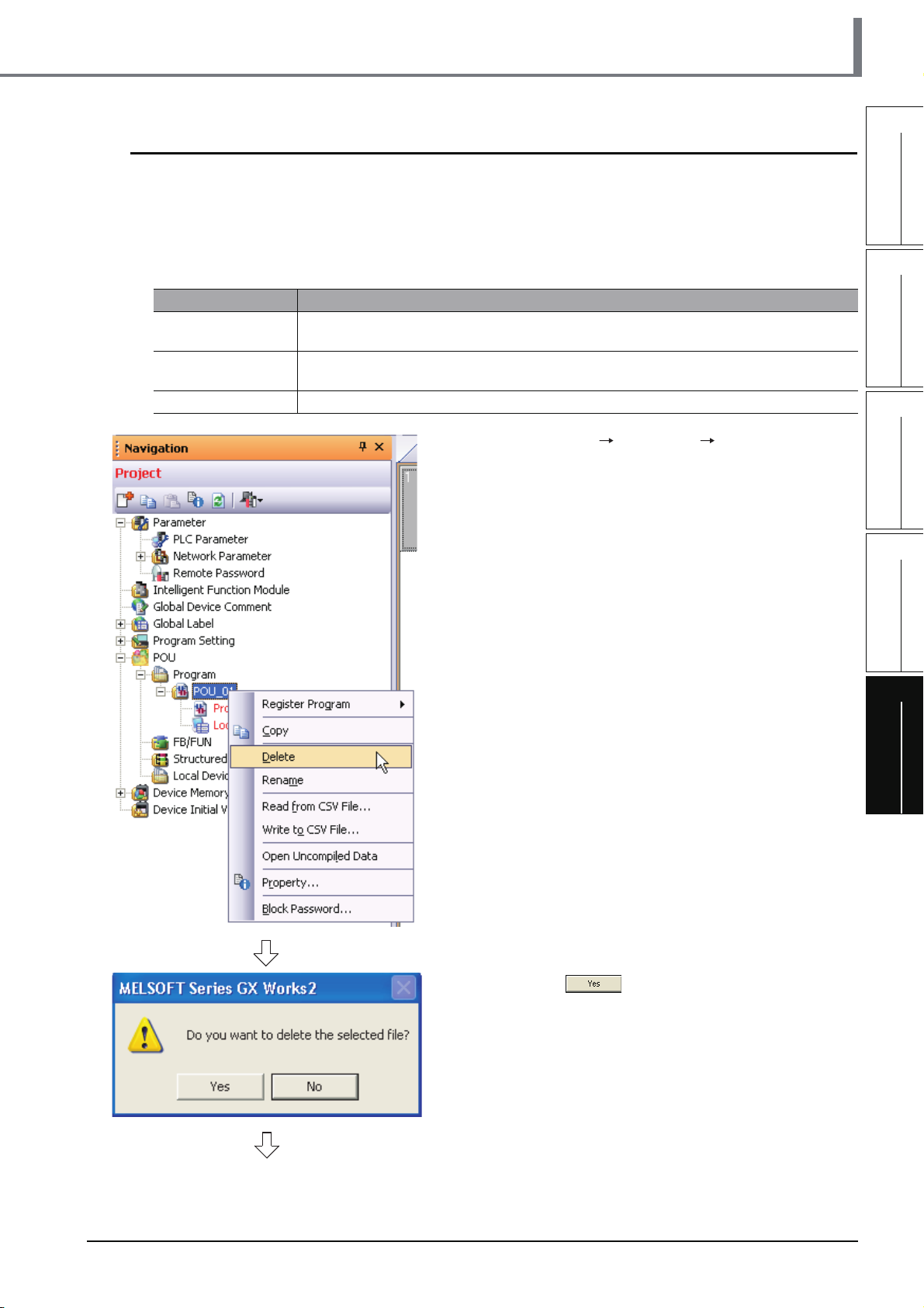
5.2 Creating a Project
5.2.5 Preparing (creating) the program configuration
Create a POU (three program blocks) for Structured Ladder/FBD program, and register the three
program blocks created in the POU to a task.
When you create a new project, GX Works2 automatically creates the Program File, Task and POU
shown in the table below.
Table 5.1 Name of Program File, Task and POU created automatically
Item Name
Program Setting
(No Execution Type)
Ta sk
POU POU_01
MAIN
Task_01
The program block "POU_01" is registered in "Task_01".
1. Select "POU" "Program" "POU_01" on the
Project view, right-click "POU_01", and then
select the menu item "Delete".
1
OVERVIEW
2
CREATED PROGRAM
AND SYSTEM
CONFIGURATION
3
CREATING PROGRAM IN
STRUCTURED LADDER/
FBD LANGUAGE
4
CREATING
PROGRAM IN ST
LANGUAGE
5
CREATING TWO OR
MORE PROGRAM
BLOCKS
(To the next page)
2. Click the button to delete the selected
data.
5.2.5 Preparing (creating) the program configuration
5 - 5
Page 94

GX Works2
5 CREATING TWO OR MORE PROGRAM BLOCKS
3. Select "POU" "Program" on the Project view,
right-click "Program", and then select the menu
item "Add New Data".
The "New Data" screen appears.
When creating a new project, GX Works2 automatically creates "POU_01 [PRG]" under "POU_Pool".
Because the language (Structured Ladder/FBD) used in this chapter is same as the language adopted in
"POU_01 [PRG]", you can use "POU_01 [PRG]" by changing its data name instead of deleting it.
4. Set the "Data Type", "Language" and "Data
Name".
Click the button to create a program block
and close the window.
Repeat the steps 3 and 4, and create three program
blocks for the tea pouring operation, water refilling
operation and warning indicating operation.
Settings
• Data Type : Select "Program Block".
• Data Name : Input the following names:
1) pouring
2) refilling
3) indicating
• Language : Select "Structured Ladder/FBD".
5 - 6
(To the next page)
5.2.5 Preparing (creating) the program configuration
Page 95

5.2 Creating a Project
5. Select "Program Setting" "No Execution
*1
Type" "MAIN" Task_01
view, right-click the Task_01, and then select
the menu item "Open Task Setting".
The Task Setting (task name*1) window appears.
*1: The Task Name is "Task_01" for this example.
on the Project
1
OVERVIEW
2
CREATED PROGRAM
AND SYSTEM
CONFIGURATION
3
6. Click the button to display the Program
Selection screen.
Click it.
7. Select the program block name.
Click the button to register the selected
program block to the Task Setting screen and close
the Program Selection screen.
Repeat the steps 6 and 7, and register three
program blocks for the tea pouring operation, water
refilling operation and warning indicating operation
in the following order to the Task Setting screen.
Settings
• Libraries : Select <ALL>.
• Program : Select the following programs in this
order.
1) pouring
2) refilling
3) indicating
Refer to the following manual for the details on registering a program block to a task:
GX Works2 Version 1 Operating Manual (Structured Project)
CREATING PROGRAM IN
STRUCTURED LADDER/
FBD LANGUAGE
4
CREATING
PROGRAM IN ST
LANGUAGE
5
CREATING TWO OR
MORE PROGRAM
BLOCKS
5.2.5 Preparing (creating) the program configuration
5 - 7
Page 96

GX Works2
5 CREATING TWO OR MORE PROGRAM BLOCKS
5.2.6 Setting labels
Refer to the following section for the global label setting procedures:
Refer to the following "Setting global labels" for settings:
3.2.5 Setting labels
Refer to the following manual for the details on global/local label setting procedures:
GX Works2 Version 1 Operating Manual (Structured Project)
Refer to the following manual for the details on programming of global labels and local labels:
MELSEC-Q/L/F Structured Programming Manual (Fundamentals)
■ Setting global labels
5 - 8
5.2.6 Setting labels
Page 97
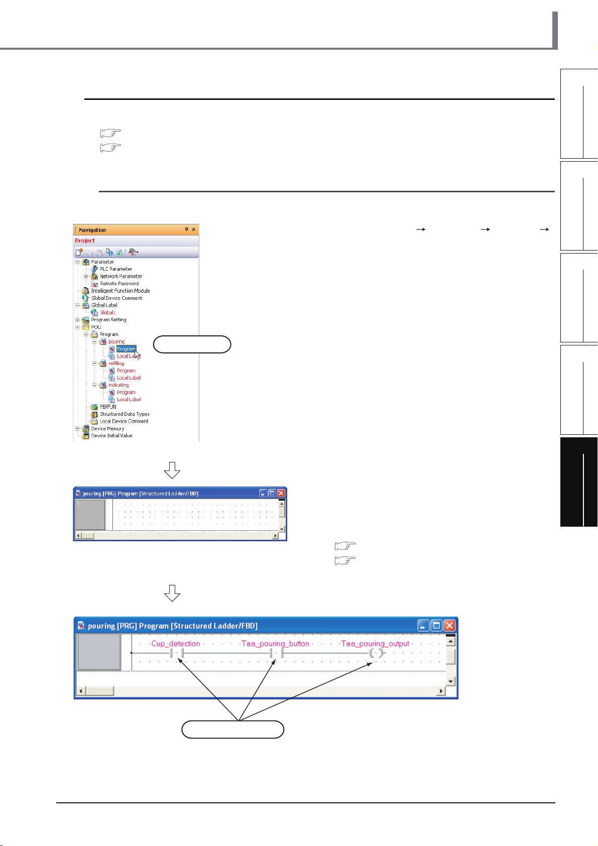
5.2.7 Creating a program
Refer to the following section and manual for the program creation procedures:
3.2.6 Creating a program
GX Works2 Version 1 Operating Manual (Structured Project)
■ Creating the program block for the tea pouring operation
Create the program block for the tea pouring operation shown in Section 5.1.2.
1. Double-click "POU" "Program" "pouring"
"Program" on the Project view to display the
pouring [PRG] Program [Structured Ladder/
FBD] screen.
5.2 Creating a Project
1
OVERVIEW
2
CREATED PROGRAM
AND SYSTEM
CONFIGURATION
3
Double-click it.
2. Create the program block for the tea pouring
operation shown in Section 5.1.2.
Refer to the following section and manual for the
program creation procedures:
3.2.6 Creating a program
GX Works2 Version 1 Operating Manual
(Structured Project)
CREATING PROGRAM IN
STRUCTURED LADDER/
FBD LANGUAGE
4
CREATING
PROGRAM IN ST
LANGUAGE
5
CREATING TWO OR
MORE PROGRAM
BLOCKS
Specify global labels.
5.2.7 Creating a program
5 - 9
Page 98

GX Works2
5 CREATING TWO OR MORE PROGRAM BLOCKS
■ Creating the program block for the water refilling operation
Create the program block for the water refilling operation shown in Section 5.1.2.
1. Double-click "POU" "Program" "refilling"
"Program" on the Project view to display the
refilling [PRG] Program [Structured Ladder/
FBD] screen.
Double-click it.
2. Create the program block for the water refilling
operation shown in
Refer to the following section and manual for the
program creation procedures:
3.2.6 Creating a program
GX Works2 Version 1 Operating Manual
(Structured Project)
Section 5.1.2.
5 - 10
Specify global labels.
5.2.7 Creating a program
Page 99

5.2 Creating a Project
■ Creating the program block for the warning indicating operation
Create the program block for the warning indicating operation shown in Section 5.1.2.
1
Double-click it.
1. Double-click "POU" "Program" "indicating"
"Program" on the Project view to display the
indicating [PRG] Program [Structured Ladder/
FBD] screen.
2. Create the program block for the warning
indicating operation shown in
Refer to the following section and manual for the
program creation procedures:
3.2.6 Creating a program
GX Works2 Version 1 Operating Manual
(Structured Project)
Section 5.1.2.
OVERVIEW
2
CREATED PROGRAM
AND SYSTEM
CONFIGURATION
3
CREATING PROGRAM IN
STRUCTURED LADDER/
FBD LANGUAGE
4
CREATING
PROGRAM IN ST
LANGUAGE
5
Specify global labels.
Specify global labels.
5.2.8 Compiling a program
Refer to the following section and manual for compiling:
3.2.7 Compiling a program
GX Works2 Version 1 Operating Manual (Structured Project)
Specify global labels.
CREATING TWO OR
MORE PROGRAM
BLOCKS
5.2.8 Compiling a program
5 - 11
Page 100

GX Works2
5 CREATING TWO OR MORE PROGRAM BLOCKS
5.3 Writing a Project to the programmable controller
Refer to the following section for the procedure to write a project to the programmable controller CPU.
3.3 Writing a Project to the programmable controller
5.4 Monitoring Operations
Execute monitoring, and check the operations.
Note that some screen shot colors have been changed for printing convenience.
GX Works2 is able to simulate programmable controller operations in offline mode.
Refer to the following manual for the simulation function:
GX Works2 Version 1 Operating Manual (Common)
5.4.1 Monitoring a program
1. Click "Project" in the view selection area on the
Navigation window to display the Project view.
Click it.
Double-click it.
(To the next page)
2. Double-click "POU" "Program" "pouring"
"Program" on the Project view to display the
pouring [PRG] Program [Structured Ladder/
FBD] screen.
Display the refilling [PRG] program [Structured
Ladder/FBD] screen and the indicating [PRG]
program [Structured Ladder/FBD] screen in the
same way.
5 - 12
5.4.1 Monitoring a program
 Loading...