

Page 1

MODBUS Interface Module User's Manual
-QJ71MB91
-GX Configurator-MB (SW1D5C-QMBU-E)
Page 2

Page 3
SAFETY PRECAUTIONS
WARNING
CAUTION
Indicates that incorrect handling may cause hazardous conditions,
resulting in death or severe injury.
Indicates that incorrect handling may cause hazardous conditions,
resulting in minor or moderate injury or property damage.
(Always read these instructions before using this product.)
Before using this product, please read this manual and the relevant manuals introduced in this manual
carefully and pay full attention to safety to handle the product correctly.
The instructions given in this manual are concerned with this product. For the safety instructions of the
programmable controller system, please read the user's manual of the CPU module used.
In this manual, the safety precautions are classified into two levels: " WARNING" and " CAUTION".
Under some circumstances, failure to observe the precautions given under " CAUTION" may lead to
serious consequences.
Observe the precautions of both levels because they are important for personal and system safety.
Make sure that the end users read this manual and then keep the manual in a safe place for future
reference.
[DESIGN PRECAUTIONS]
WARNING
For the operating status of each station after a communication failure, refer to relevant manuals for
each network.
Failure to do so may result in an accident due to an incorrect output or malfunction.
When connecting a peripheral with the CPU module or connecting an external device, such as a
personal computer, with an intelligent function module to modify data of a running programmable
controller, configure an interlock circuit in the program to ensure that the entire system will always
operate safely.
For other forms of control (such as program modification or operating status change) of a running
programmable controller, read the relevant manuals carefully and ensure that the operation is safe
before proceeding.
Especially, when a remote programmable controller is controlled by an external device, immediate
action cannot be taken if a problem occurs in the programmable controller due to a communication
failure. To prevent this, configure an interlock circuit in the sequence program, and determine
corrective actions to be taken between the external device and CPU module in case of a
communication failure.
Do not write any data to the "system area" of the buffer memory in the intelligent function module.
Also, do not use any "use prohibited" signals as an output signal from the programmable controller
CPU to the intelligent function module.
Doing so may cause malfunction of the programmable controller system.
A - 1
Page 4

[DESIGN PRECAUTIONS]
CAUTION
Do not install the control lines or communication cables together with the main circuit lines or power
cables.
Keep a distance of 100mm or more between them.
Failure to do so may result in malfunction due to noise.
[INSTALLATION PRECAUTIONS]
CAUTION
Use the programmable controller in an environment that meets the general specifications in the
user's manual for the CPU module used.
Failure to do so may result in electric shock, fire, malfunction, or damage to or deterioration of the
product.
To mount the module, while pressing the module mounting lever located in the lower part of the
module, fully insert the module fixing projection(s) into the hole(s) in the base unit and press the
module until it snaps into place.
Incorrect mounting may cause malfunction, failure or drop of the module.
When using the programmable controller in an environment of frequent vibrations, fix the module
with a screw.
Tighten the terminal screws within the specified torque range.
Undertightening can cause drop of the screw, short circuit or malfunction.
Overtightening can damage the screw and/or module, resulting in drop, short circuit, or malfunction.
Shut off the external power supply (all phases) used in the system before mounting or removing a
module. Failure to do so may result in damage to the product.
Do not directly touch any conductive parts and electronic components of the module.
Doing so can cause malfunction or failure of the module.
A - 2
Page 5

[WIRING PRECAUTIONS]
WARNING
Shut off the external power supply (all phases) used in the system before wiring.
Failure to do so may result in electric shock or damage to the product.
After wiring, attach the included terminal cover to the module before turning it on for operation.
Failure to do so may result in electric shock.
]
CAUTION
Connectors for external devices must be crimped or pressed with the tool specified by the
manufacturer, or must be correctly soldered.
Incomplete connections may cause short circuit, fire, or malfunction.
Securely connect the connector to the module.
Check the rated voltage and terminal layout before wiring to the module, and connect the cables
correctly.
Connecting a power supply with a different voltage rating or incorrect wiring may cause a fire or
failure.
Place the cables in a duct or clamp them.
If not, dangling cable may swing or inadvertently be pulled, resulting in damage to the module or
cables or malfunction due to poor contact.
Check the interface type and correctly connect the cable.
Incorrect wiring (connecting the cable to an incorrect interface) may cause failure of the module and
external device.
Tighten the terminal screws within the specified torque range.
Undertightening can cause drop of the screw, short circuit or malfunction.
Overtightening can damage the screw and/or module, resulting in drop, short circuit, or malfunction.
When disconnecting the cable from the module, do not pull the cable by the cable part.
For the cable with connector, hold the connector part of the cable.
For the cable connected to the terminal block, loosen the terminal screw.
Failure to do so may result in damage to the module or cable or malfunction due to poor contact.
Prevent foreign matter such as dust or wire chips from entering the module.
Such foreign matter can cause a fire, failure, or malfunction.
A protective film is attached to the top of the module to prevent foreign matter, such as wire chips,
from entering the module during wiring.
Do not remove the film during wiring.
Remove it for heat dissipation before system operation.
A - 3
Page 6
[STARTUP AND MAINTENANCE PRECAUTIONS]
WARNING
Do not touch any terminal while power is on.
Doing so will cause electric shock.
Shut off the external power supply (all phases) used in the system before cleaning the module or
retightening the terminal screws or module fixing screws.
Failure to do so may cause the module to fail or malfunction.
Undertightening can cause drop of the screw, short circuit or malfunction.
Overtightening can damage the screw and/or module, resulting in drop, short circuit, or malfunction.
CAUTION
Before performing online operations (especially, program modification, forced output or operating
status change) by connecting a peripheral device to a running CPU, read the manual carefully and
ensure the safety.
Improper operation may damage machines or cause accidents.
Do not disassemble or modify the modules.
Doing so may cause failure, malfunction, injury, or a fire.
Use any radio communication device such as a cellular phone or PHS (Personal Handy-phone
System) more than 25cm away in all directions from the programmable controller.
Failure to do so may cause malfunction.
Shut off the external power supply (all phases) used in the system before mounting or removing a
module.
Failure to do so may cause the module to fail or malfunction.
After the first use of the product, do not mount/remove the module to/from the base unit, and the
terminal block to/from the module more than 50 times (IEC 61131-2 compliant) respectively.
Exceeding the limit of 50 times may cause malfunction.
Before handling the module, touch a conducting object such as a grounded metal to discharge the
static electricity from the human body.
Failure to do so may cause the module to fail or malfunction.
[DISPOSAL PRECAUTIONS]
CAUTION
When disposing of this product, treat is as an industrial waste.
A - 4
Page 7

CONDITIONS OF USE FOR THE PRODUCT
(1) Mitsubishi programmable controller ("the PRODUCT") shall be used in conditions;
i) where any problem, fault or failure occurring in the PRODUCT, if any, shall not lead to any major
or serious accident; and
ii) where the backup and fail-safe function are systematically or automatically provided outside of
the PRODUCT for the case of any problem, fault or failure occurring in the PRODUCT.
(2) The PRODUCT has been designed and manufactured for the purpose of being used in general
industries.
MITSUBISHI SHALL HAVE NO RESPONSIBILITY OR LIABILITY (INCLUDING, BUT NOT
LIMITED TO ANY AND ALL RESPONSIBILITY OR LIABILITY BASED ON CONTRACT,
WARRANTY, TORT, PRODUCT LIABILITY) FOR ANY INJURY OR DEATH TO PERSONS OR
LOSS OR DAMAGE TO PROPERTY CAUSED BY the PRODUCT THAT ARE OPERATED OR
USED IN APPLICATION NOT INTENDED OR EXCLUDED BY INSTRUCTIONS, PRECAUTIONS,
OR WARNING CONTAINED IN MITSUBISHI'S USER, INSTRUCTION AND/OR SAFETY
MANUALS, TECHNICAL BULLETINS AND GUIDELINES FOR the PRODUCT.
("Prohibited Application")
Prohibited Applications include, but not limited to, the use of the PRODUCT in;
• Nuclear Power Plants and any other power plants operated by Power companies, and/or any
other cases in which the public could be affected if any problem or fault occurs in the PRODUCT.
• Railway companies or Public service purposes, and/or any other cases in which establishment of
a special quality assurance system is required by the Purchaser or End User.
• Aircraft or Aerospace, Medical applications, Train equipment, transport equipment such as
Elevator and Escalator, Incineration and Fuel devices, Vehicles, Manned transportation,
Equipment for Recreation and Amusement, and Safety devices, handling of Nuclear or
Hazardous Materials or Chemicals, Mining and Drilling, and/or other applications where there is a
significant risk of injury to the public or property.
Notwithstanding the above, restrictions Mitsubishi may in its sole discretion, authorize use of the
PRODUCT in one or more of the Prohibited Applications, provided that the usage of the PRODUCT
is limited only for the specific applications agreed to by Mitsubishi and provided further that no
special quality assurance or fail-safe, redundant or other safety features which exceed the general
specifications of the PRODUCTs are required. For details, please contact the Mitsubishi
representative in your region.
A - 5
Page 8

REVISIONS
* The manual number is given on the bottom left of the back cover.
Print Date * Manual Number Revision
Nov., 2005 SH(NA)-080578ENG-A First edition
Feb., 2006 SH(NA)-080578ENG-B Modifications
Section 2.1, 2.3, 10.1
Oct., 2006 SH(NA)-080578ENG-C Modifications
SAFETY PRECAUTIONS, Section 2.1, 6.6, 10.1
Jan., 2008 SH(NA)-080578ENG-D Modifications
SAFETY PRECAUTIONS, ABOUT THE GENERIC TERMS AND
ABBREVIATIONS, MEANINGS AND DEFINITIONS OF TERMS, Section 2.1,
2.4, 3.1, 3.2.1, 3.3.1, 3.3.2, 3.4.1, 4.1.6, 5.1, 5.2.1, 6.1, 6.3, 6.4.1, 6.4.2, 6.5.2,
6.6, 7.2.1, 7.3.1, 7.3.2, Chapter 8, 9.1.2, 9.3.1, 9.3.2, 10.2, 10.3, 11.1, 11.2,
11.4.1, 11.4.3, 11.5.1, Appendix 3
Added
Section 2.3
Section 2.3 changed to Section 2.4.
Mar., 2008 SH(NA)-080578ENG-E Modifications
COMPLIANCE WITH EMC AND LOW VOLTAGE DIRECTIVES, Section 2.1, 2.4,
4.16, 6.3, 6.4.1, 8.5, 8.6, Appendix 3
May, 2008 SH(NA)-080578ENG-F Change of a term
"PLC" was changed to "programmable controller".
Modifications
ABOUT THE GENERIC TERMS AND ABBREVIATIONS, Section 2.1, 4.16, 6.1,
6.6, 7.3.1, 8.2.1, 8.3.1, 8.3.3, 8.4, 8.5, 8.6, 10.2, 10.3, 11.4.3
Apr., 2009 SH(NA)-080578ENG-G Modifications
Section 1.1, 2.1, 2.4, 3.1, 3.4.1, 3.5.1, 4.16, 5.2.1, 8.2.1, 9.1.1 to 9.3.2,
10.1 to 10.3, 11.1, 11.4.3
Added
Section 10.4, Appendix 1
Appendix numbers 1 and 2 changed to 2 and 3.
Jan., 2013 SH(NA)-080578ENG-H Modifications
SAFETY PRECAUTIONS, COMPLIANCE WITH EMC AND LOW VOLTAGE
DIRECTIVES, ABOUT THE GENERIC TERMS AND ABBREVIATIONS,
Section 2.1, 2.3, 2.4, 3.3.2, 4.16, 7.1, 8.2.2, 11.4.3
Added
CONDITIONS OF USE FOR THE PRODUCT, Section 9.4
Sep., 2016 SH(NA)-080578ENG-I Modifications
SAFETYABOUT THE GENERIC TERMS AND ABBREVIATIONS, Section 1.1,
2.1, 2.2, 2.3, 2.4, 3.3.1, 4.2.1, 4.16, 5.2.1, 6.3, 9.2.1, 9.2.2, 9.2.3, 9.3.1, 9.3.2,
10.3, Appendix 3
Japanese Manual Version SH-080547-J
This manual confers no industrial property rights or any rights of any other kind, nor does it confer any patent licenses.
Mitsubishi Electric Corporation cannot be held responsible for any problems involving industrial property rights which may
occur as a result of using the contents noted in this manual.
© 2005 MITSUBISHI ELECTRIC CORPORATION
A - 6
Page 9

INTRODUCTION
Thank you for purchasing the Mitsubishi MELSEC-Q series programmable controllers.
Before using this product, please read this manual and the relevant manuals carefully and develop
familiarity with the functions and performance of the MELSEC-Q series programmable controller to handle
the product correctly.
When applying the program examples introduced in this manual to an actual system, ensure the
applicability and confirm that it will not cause system control problems.
CONTENTS
SAFETY PRECAUTIONS ................................................................................................................................. A - 1
CONDITIONS OF USE FOR THE PRODUCT..................................................................................................A - 5
REVISIONS....................................................................................................................................................... A - 6
INTRODUCTION...............................................................................................................................................A - 7
CONTENTS ...................................................................................................................................................... A - 7
COMPLIANCE WITH EMC AND LOW VOLTAGE DIRECTIVES................................................................... A - 12
THE MANUAL'S USAGE AND STRUCTURE ................................................................................................A - 13
ABOUT THE GENERIC TERMS AND ABBREVIATIONS ..............................................................................A - 15
MEANINGS AND DEFINITIONS OF TERM ................................................................................................... A - 16
PRODUCT CONFIGURATION ....................................................................................................................... A - 16
CHAPTER1 OVERVIEW 1 - 1 to 1 - 4
1.1 Features........................................................................................................................................... 1 - 1
CHAPTER2 SYSTEM CONFIGURATION 2 - 1 to 2 - 10
2.1 Applicable Systems ......................................................................................................................... 2 - 1
2.2 Network Configuration ..................................................................................................................... 2 - 3
2.3 Precautions for System Configuration ............................................................................................. 2 - 7
2.4 How to Check the Function Version/Software Version .................................................................... 2 - 8
CHAPTER3 SPECIFICATIONS 3 - 1 to 3 - 23
3.1 Performance Specifications............................................................................................................. 3 - 1
3.2 RS-232 Interface Specification ........................................................................................................ 3 - 3
3.2.1 RS-232 connector specification................................................................................................ 3 - 3
3.2.2 RS-232 cable specification ....................................................................................................... 3 - 5
3.3 RS-422/485 Interface Specification ................................................................................................. 3 - 6
3.3.1 RS-422/485 terminal block specification .................................................................................. 3 - 6
3.3.2 RS-422/485 cable specification ................................................................................................ 3 - 7
3.3.3 Precautions when transferring data using RS-422/485 line ..................................................... 3 - 8
3.4 I/O Signals for Programmable Controller CPU .............................................................................. 3 - 10
3.4.1 I/O signal list ........................................................................................................................... 3 - 10
3.5 Applications and Assignment of Buffer Memory ............................................................................ 3 - 13
A - 7
Page 10

3.5.1 Buffer memory list................................................................................................................... 3 - 13
CHAPTER4 MODBUS STANDARD FUNCTIONS 4 - 1 to 4 - 60
4.1 MODBUS Standard Function Support List ...................................................................................... 4 - 1
4.2 Frame Specifications ..................................................................................................................... 4 - 10
4.2.1 Frame mode ........................................................................................................................... 4 - 11
4.3 Protocol Data Unit Formats by Functions ......................................................................................4 - 15
4.4 Read Coils (FC: 01) ....................................................................................................................... 4 - 18
4.5 Read Discrete Inputs (FC: 02) ....................................................................................................... 4 - 19
4.6 Read Holding Registers (FC: 03)................................................................................................... 4 - 20
4.7 Read Input Registers (FC: 04) ....................................................................................................... 4 - 21
4.8 Write Single Coil (FC: 05) .............................................................................................................. 4 - 22
4.9 Write Single Register (FC: 06) ....................................................................................................... 4 - 23
4.10 Read Exception Status (FC: 07) .................................................................................................... 4 - 24
4.11 Diagnostics (FC: 08) ...................................................................................................................... 4 - 25
4.11.1 Return query data (sub-function code: 00) ............................................................................. 4 - 25
4.11.2 Restart communications option (sub-function code: 01)......................................................... 4 - 26
4.11.3 Return diagnostic register (sub-function code: 02) ................................................................. 4 - 28
4.11.4 Change ASCII input delimiter (sub-function code: 03)............................................................ 4 - 30
4.11.5 Force listen only mode (sub-function code: 04)...................................................................... 4 - 31
4.11.6 Clear counters and diagnostic register (sub-function code: 10) ............................................. 4 - 33
4.11.7 Return bus message count (sub-function code: 11)............................................................... 4 - 35
4.11.8 Return bus communication error count (sub-function code: 12) ............................................. 4 - 36
4.11.9 Return bus exception error count (sub-function code: 13)...................................................... 4 - 37
4.11.10 Return slave message count (sub-function code: 14) ............................................................ 4 - 38
4.11.11 Return slave no response count (sub-function code: 15) ....................................................... 4 - 39
4.11.12 Return slave NAK count (sub-function code: 16).................................................................... 4 - 40
4.11.13 Return slave busy count (sub-function code: 17) ................................................................... 4 - 41
4.11.14 Return bus character overrun count (sub-function code: 18) ................................................. 4 - 42
4.11.15 Return IOP overrun error count (sub-function code: 19) ........................................................ 4 - 43
4.11.16 Clear overrun counter and flag (sub-function code: 20) ......................................................... 4 - 44
4.12 Get Communications Event Counter (FC: 11) ............................................................................... 4 - 45
4.13 Get Communications Event Log (FC: 12) ...................................................................................... 4 - 47
4.14 Write Multiple Coils (FC: 15).......................................................................................................... 4 - 50
4.15 Write Multiple Registers (FC: 16)................................................................................................... 4 - 52
4.16 Report Slave ID (FC: 17) ............................................................................................................... 4 - 53
4.17 Read File Record (FC: 20) (SC: 06) .............................................................................................. 4 - 55
4.18 Write File Record (FC: 21) (SC: 06) .............................................................................................. 4 - 57
4.19 Mask Write Register (FC: 22) ........................................................................................................ 4 - 59
4.20 Read/Write Multiple Registers (FC: 23) ......................................................................................... 4 - 60
CHAPTER5 FUNCTIONS 5 - 1 to 5 - 22
5.1 Function List .................................................................................................................................... 5 - 1
A - 8
Page 11

5.2 Master Function ............................................................................................................................... 5 - 3
5.2.1 Automatic communication function ...........................................................................................5 - 3
5.2.2 Communication by dedicated instructions .............................................................................. 5 - 16
5.3 Slave Function ............................................................................................................................... 5 - 17
5.3.1 Automatic response function .................................................................................................. 5 - 17
5.3.2 MODBUS device assignment function ................................................................................... 5 - 18
5.3.3 Link operation function ........................................................................................................... 5 - 21
CHAPTER6 PRE-OPERATIONAL PROCEDURES AND SETTINGS 6 - 1 to 6 - 24
6.1 Handling Precautions....................................................................................................................... 6 - 1
6.2 Pre-Operational Procedures and Settings ....................................................................................... 6 - 2
6.3 Part Names...................................................................................................................................... 6 - 4
6.4 Unit Tests......................................................................................................................................... 6 - 6
6.4.1 Hardware test ........................................................................................................................... 6 - 6
6.4.2 Self-loopback test ..................................................................................................................... 6 - 8
6.5 Connection to a Target Device ...................................................................................................... 6 - 11
6.5.1 How to connect the RS-232 interface..................................................................................... 6 - 12
6.5.2 How to connect the RS-422/485 interface.............................................................................. 6 - 14
6.6 Intelligent Function Module Switch Setting .................................................................................... 6 - 19
6.7 Maintenance, Inspection ................................................................................................................ 6 - 24
6.7.1 Maintenance, inspection......................................................................................................... 6 - 24
6.7.2 When removing or installing the module ................................................................................ 6 - 24
CHAPTER7 PARAMETER SETTING 7 - 1 to 7 - 31
7.1 Parameter Settings and Setting Procedure .....................................................................................7 - 1
7.2 Automatic Communication Parameter ............................................................................................. 7 - 4
7.2.1 Automatic communication parameter details........................................................................... 7 - 4
7.3 MODBUS Device Assignment Parameter ..................................................................................... 7 - 11
7.3.1 MODBUS device assignment to the programmable controller CPU device memory ............. 7 - 13
7.3.2 MODBUS extended file register assignment to the programmable controller
CPU file register ..................................................................................................................... 7 - 23
7.3.3 QJ71MB91 buffer memory assignment .................................................................................. 7 - 24
7.3.4 Specifying the error status read device .................................................................................. 7 - 26
7.3.5 Specifying access target when mounted to MELSECNET/H remote I/O station .................... 7 - 29
7.3.6 Specifying the CPU response monitoring timer ...................................................................... 7 - 30
CHAPTER8 UTILITY PACKAGE (GX Configurator-MB) 8 - 1 to 8 - 37
8.1 Functions of the Utility Package ...................................................................................................... 8 - 1
8.2 Installing and Uninstalling the Utility Package ................................................................................. 8 - 2
8.2.1 Handling precautions ................................................................................................................ 8 - 2
8.2.2 Operating environment ............................................................................................................. 8 - 5
8.3 Utility Package Operation ................................................................................................................ 8 - 7
8.3.1 Common utility package operations ......................................................................................... 8 - 7
8.3.2 Operation overview................................................................................................................. 8 - 10
A - 9
Page 12

8.3.3 Starting the Intelligent function module utility ......................................................................... 8 - 12
8.4 Initial Setting .................................................................................................................................. 8 - 15
8.4.1 Automatic communication parameter ..................................................................................... 8 - 17
8.4.2 MODBUS device assignment parameter ................................................................................ 8 - 19
8.5 Auto Refresh Setting...................................................................................................................... 8 - 22
8.6 Monitor/Test ................................................................................................................................... 8 - 24
8.6.1 X/Y Monitor/test ...................................................................................................................... 8 - 29
8.6.2 MODBUS device assignment parameter status ..................................................................... 8 - 31
8.6.3 Automatic communication status ............................................................................................ 8 - 32
8.6.4 Error log .................................................................................................................................. 8 - 34
8.6.5 Communication status ............................................................................................................ 8 - 35
CHAPTER9 PROGRAMMING 9 - 1 to 9 - 45
9.1 Parameter Setting ............................................................................................................................ 9 - 1
9.1.1 Automatic communication parameters ..................................................................................... 9 - 1
9.1.2 MODBUS device assignment parameters ................................................................................ 9 - 4
9.2 Program Example for Normal System Configuration....................................................................... 9 - 8
9.2.1 Automatic communication parameters ..................................................................................... 9 - 8
9.2.2 MODBUS device assignment parameters .............................................................................. 9 - 14
9.2.3 When using the automatic communication function and the communication by dedicated
instructions on the same channel .......................................................................................... 9 - 18
9.3 Program Examples for Use in MELSECNET/H Remote I/O Network............................................ 9 - 25
9.3.1 Automatic communication parameters ................................................................................... 9 - 25
9.3.2 MODBUS device assignment parameters .............................................................................. 9 - 37
9.4 Program Examples for the Redundant System ............................................................................. 9 - 45
CHAPTER10 DEDICATED INSTRUCTIONS 10 - 1 to 10 - 32
10.1 Dedicated Instruction List and Available Devices .......................................................................... 10 - 1
10.2 Z(P).MBRW ................................................................................................................................... 10 - 2
10.3 Z(P).MBREQ................................................................................................................................ 10 - 14
10.4 ZP.UINI ........................................................................................................................................ 10 - 25
CHAPTER11 TROUBLESHOOTING 11 - 1 to 11 - 47
11.1 Troubleshooting ............................................................................................................................. 11 - 1
11.2 Checking QJ71MB91 Status........................................................................................................ 11 - 11
11.3 Checking the Communication Status of QJ71MB91.................................................................... 11 - 17
11.4 Error Codes ................................................................................................................................. 11 - 21
11.4.1 Error code storage area........................................................................................................ 11 - 21
11.4.2 Exception code list................................................................................................................ 11 - 28
11.4.3 Error code list........................................................................................................................ 11 - 30
11.5 Turning Off the ERR. LED ........................................................................................................... 11 - 41
11.5.1 Turning off the ERR. LED by GX Configurator-MB............................................................... 11 - 41
11.5.2 Turning off the ERR. LED by sequence program ................................................................. 11 - 45
11.5.3 Turning off the ERR. LED by request message from the master ......................................... 11 - 47
A - 10
Page 13

APPENDICES App - 1 to App - 13
Appendix 1 Function Upgrade of the QJ71MB91 ................................................................................ App - 1
Appendix 2 A Series Modules .............................................................................................................App - 2
Appendix 2.1 Comparisons in performance specifications.............................................................App - 2
Appendix 2.2 Functional comparisons ........................................................................................... App - 3
Appendix 2.3 Utilization of existing programs ................................................................................ App - 4
Appendix 3 Processing Time...............................................................................................................App - 7
Appendix 4 External Dimensions....................................................................................................... App - 13
INDEX Index - 1 to Index - 2
A - 11
Page 14

COMPLIANCE WITH EMC AND LOW VOLTAGE DIRECTIVES
(1) Method of ensuring compliance
To ensure that Mitsubishi programmable controllers maintain EMC and Low Voltage
Directives when incorporated into other machinery or equipment, certain measures
may be necessary. Please refer to one of the following manuals.
• QCPU User's Manual (Hardware Design, Maintenance and Inspection)
• Safety Guidelines
(This manual is included with the CPU module or base unit.)
The CE mark on the side of the programmable controller indicates compliance with
EMC and Low Voltage Directives.
(2) Additional measures
No additional measures are necessary for the compliance of this product with EMC
and Low Voltage Directives.
A - 12
Page 15

THE MANUAL'S USAGE AND STRUCTURE
This manual lists the process and functions up to systems operation using
the MODBUS interface module (QJ71MB91), divided into subjects.
Refer to the corresponding section when you need to know the following:
(1) Features ( CHAPTER 1)
CHAPTER 1 describes the features of the QJ71MB91.
(2) System Configuration ( CHAPTER 2)
Section 2.1 lists the applicable programmable controller CPU and corresponding
software package.
Section 2.2 lists network configuration example.
(3) Performance and Specifications ( CHAPTER 3)
Section 3.1 lists the performance specifications of the QJ71MB91.
Section 3.2 and 3.3 list the specifications of each interface.
Section 3.4 and 3.5 list the I/O signals and buffer memory of the QJ71MB91.
(4) MODBUS Standard Functions Supporting QJ71MB91 ( CHAPTER 4)
Section 4.1 lists the MODBUS standard functions supporting QJ71MB91.
Section 4.2 to 4.20 list the frame specifications of the MODBUS standard functions
supporting QJ71MB91.
(5) Usable Functions ( CHAPTER 5)
CHAPTER 5 describes the functions of the QJ71MB91.
(6) Settings and Procedures Necessary for System Operation
CHAPTER 6)
(
CHAPTER 6 describes the pre-operation settings and procedures.
(7) Parameter Settings of the QJ71MB91 ( CHAPTER 7)
CHAPTER 7 describes the parameter setting procedures and parameter details.
(8) Setting Parameters from the Utility Package ( CHAPTER 8)
CHAPTER 8 describes how to use the utility package.
(9) Setting Parameters from the Sequence Program ( CHAPTER 9)
CHAPTER 9 describes the I/O signals used for parameter settings, the I/O signal
timing charts, and program examples.
(10)Reading from/Writing to the MODBUS Device using the Sequence
Program ( CHAPTER 10)
CHAPTER 10 describes the dedicated instructions designed to read or write
MODBUS device data with sequence programs.
A - 13
Page 16

(11)Error Code and Corresponding Process Details (
Section 11.1 lists troubleshooting.
Section 11.2 lists the confirmation methods of the module conditions.
Section 11.3 lists the confirmation of the communication conditions.
Section 11.4 lists the storage location and details of the error codes.
Section 11.5 lists the methods to turn off the ERR. LED.
About the notation of the numerical values used in this manual
In this manual, the numerical values with the suffix "H" are displayed in
hexadecimal values.
(Example) 10......Decimal
H....Hexadecimal
10
CHAPTER 11)
A - 14
Page 17

ABOUT THE GENERIC TERMS AND ABBREVIATIONS
Unless otherwise specified, this manual uses the following generic terms
and abbreviations to explain the QJ71MB91 MODBUS interface module.
General term/Abbreviation Description
QJ71MB91 Abbreviation for the QJ71MB91 MODBUS interface module.
GX Developer
GX Works2
MODBUS Protocol Generic term for the protocol designed to use MODBUS protocol messages.
FC Abbreviation for the function code.
SC Abbreviation for the sub code.
Programmable controller
CPU
Basic model QCPU Generic term for the Q00JCPU, Q00CPU, and Q01CPU
Redundant CPU Generic term for the Q12PRHCPU and Q25PRHCPU
Universal model QCPU
C Controller module
Master The side from which a request is sent to execute a function.
Slave
Master function
Slave function
Request message
Response message The message with which the slave returns a function execution result to the master.
Target device
Personal computer Abbreviation for DOS/V personal computers of IBM PC/AT and compatible.
MELSECNET/H Abbreviation of the MELSECNET/H network system.
MBRW Abbreviation for Z.MBRW or ZP.MBRW.
MBREQ Abbreviation for Z.MBREQ or ZP.MBREQ.
UINI Abbreviation for ZP.UINI.
Windows 7
The product name of the software package for the MELSEC programmable controllers
Generic term for the Q00JCPU, Q00CPU, Q01CPU, Q02CPU, Q02HCPU, Q06HCPU,
Q12HCPU, Q25HCPU, Q02PHCPU, Q06PHCPU, Q12PHCPU, Q25PHCPU, Q12PRHCPU,
Q25PRHCPU, Q00UJCPU, Q00UCPU, Q01UCPU, Q02UCPU, Q03UDCPU, Q03UDVCPU,
Q03UDECPU, Q04UDHCPU, Q04UDVCPU, Q04UDEHCPU, Q06UDHCPU, Q06UDVCPU,
Q06UDEHCPU, Q10UDHCPU, Q10UDEHCPU, Q13UDHCPU, Q13UDVCPU,
Q13UDEHCPU, Q20UDHCPU, Q20UDEHCPU, Q26UDHCPU, Q26UDVCPU,
Q26UDEHCPU, Q50UDEHCPU, and Q100UDEHCPU
Generic term for the Q00UJCPU, Q00UCPU, Q01UCPU, Q02UCPU, Q03UDCPU,
Q03UDVCPU, Q03UDECPU, Q04UDHCPU, Q04UDVCPU, Q04UDEHCPU, Q06UDHCPU,
Q06UDVCPU, Q06UDEHCPU, Q10UDHCPU, Q10UDEHCPU, Q13UDHCPU,
Q13UDVCPU, Q13UDEHCPU, Q20UDHCPU, Q20UDEHCPU, Q26UDHCPU,
Q26UDVCPU, Q26UDEHCPU, Q50UDEHCPU, and Q100UDEHCPU
Generic term for the Q06CCPU-V-H01, Q06CCPU-V, Q06CCPU-V-B, Q12DCCPU-V,
Q24DHCCPU-V, Q24DHCCPU-VG, Q24DHCCPU-LS, and Q26DHCCPU-LS
The side where the execution request from the master is processed and its execution
result is sent.
The function that allows communication with the MODBUS compatible slave device as the
master of MODBUS.
The function that allows communication with the MODBUS compatible master device as the
slave of MODBUS.
The message used to give a function execution request to the slave In the MODBUS
protocol, a function execution request is given from the master to the slave.
A function execution request cannot be given from the slave to the master.
Abbreviation of the connected communication targets (devices corresponding to personal
computers, other QJ71MB91 MODBUS interface modules, MODBUS protocols) for data
communication.
Generic term for the following:
Microsoft Windows 7 Starter Operating System,
Microsoft Windows 7 Home Premium Operating System,
Microsoft Windows 7 Professional Operating System,
Microsoft Windows 7 Ultimate Operating System,
Microsoft Windows 7 Enterprise Operating System
A - 15
Page 18

General term/Abbreviation Description
Generic term for the following:
Windows Vista
Windows XP
Microsoft Windows
Microsoft Windows
Microsoft Windows
Microsoft Windows
Microsoft Windows
Generic term for the following:
Microsoft Windows XP Professional Operating System,
Microsoft Windows XP Home Edition Operating System
Vista Home Basic Operating System,
Vista Home Premium Operating System,
Vista Business Operating System,
Vista Ultimate Operating System,
Vista Enterprise Operating System
MEANINGS AND DEFINITIONS OF TERM
The following explains the meanings and definitions of the terms used in
this manual.
Ter m Description
MODBUS protocol
MODBUS device Device used for communication using the MODBUS protocol
Sequence program
Device memory
Listen only mode Mode detaching the slave station from the circuit.
Protocol used on an open MODBUS network which performs master-slave communications
over a serial bus or TCP/IP
Programming system devised to make a contact type sequence compatible with the
programmable controller language as-is. Draw two vertical control buses and describe
contacts, etc.
between the buses to perform programming.
Memory provided for the programmable controller CPU to record the data handled in
sequence program operation.
PRODUCT CONFIGURATION
The following indicates the product configuration of the QJ71MB91
MODBUS interface module.
Model Product name Quantity
QJ71MB91 MODBUS interface module 1
QJ71MB91
SW1D5C-QMBU-E GX Configurator-MB Version 1 (1-license product) (CD-ROM) 1
SW1D5C-QMBU-EA GX Configurator-MB Version 1 (Multiple-license product) (CD-ROM) 1
Terminal resistor 330 1/4 W (for RS-422 communication) 2
Terminal resistor 110 1/2 W (for RS-485 communication) 2
A - 16
Page 19
1
MODBUS slave device
(Third party sensor, etc)
MODBUS slave device
(Third party programmable
controller)
Device memory
MODBUS slave device
(Third party remote I/O, etc)
Holding register
Holding register
Holding register
RS-485
Programmable controller CPU
Device memory
Auto Refresh
QJ71MB91 (Master function)
Read
Read
Read
Write
Buffer memory
Automatically issues the
MODBUS device read/write
request message to Slave.
OVERVIEW
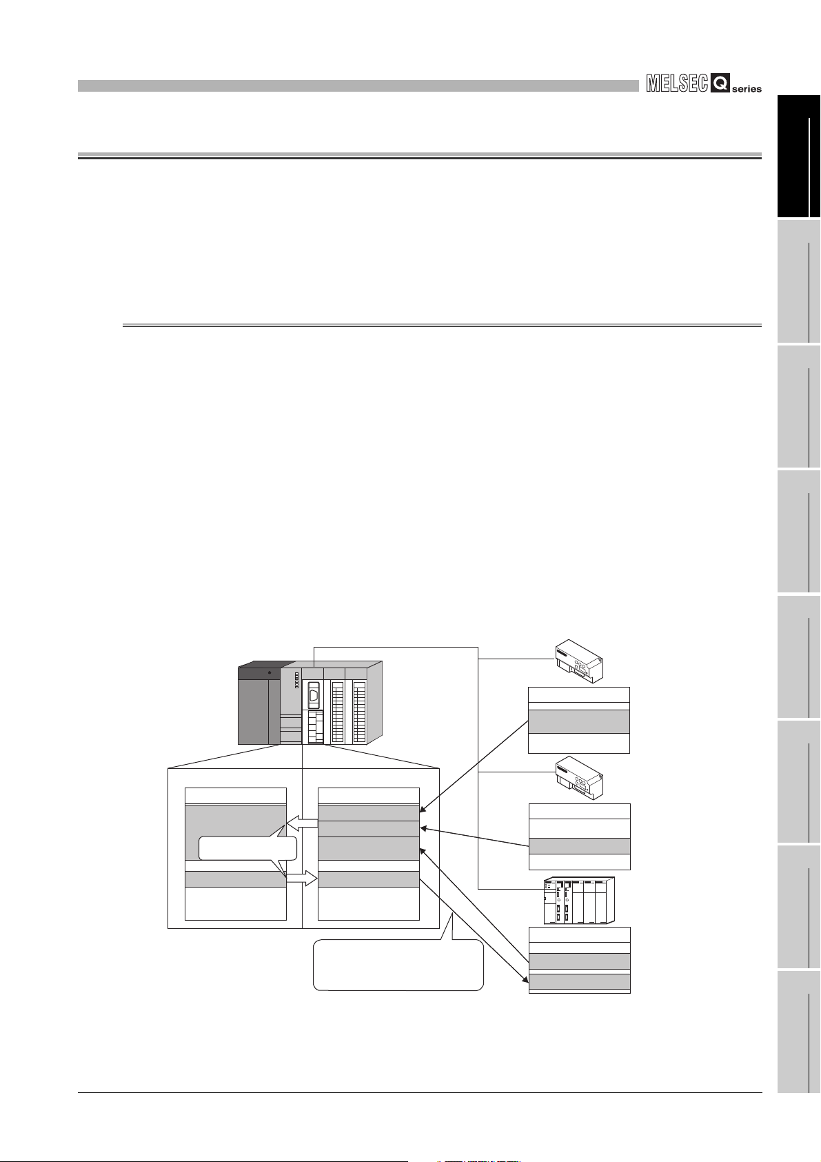
CHAPTER1 OVERVIEW
This manual explains the specifications, functions, programming, and troubleshooting of
the MELSEC-Q series QJ71MB91 MODBUS interface module (hereinafter referred to as
QJ71MB91).
The QJ71MB91 is used when a MELSEC-Q series programmable controller is connected
to the MODBUS protocol system.
1.1 Features
1
2
OVERVIEW
SYSTEM
CONFIGURATION
(1) Supporting the master function of MODBUS communication
The QJ71MB91 supports the master function of the MODBUS communication, which
is an open network system for factory automation, and thereby is compatible with
various MODBUS slave devices (hereinafter referred to as slave) of other
manufacturers.
The master function includes the following two functions.
(a) Automatic communication function
By setting the automatic communication parameters, MODBUS device data can
be automatically read from or written to the slaves at the specified intervals using
the QJ71MB91 buffer memory.
Data can be transferred between the QJ71MB91 buffer memory and
programmable controller CPU device memory by making the auto refresh setting
with the utility package (GX Configurator-MB) or by accessing any intelligent
function module device with a sequence program.
*1
3
SPECIFICATIONS
4
MODBUS STANDARD
FUNCTIONS
5
FUNCTION
6
Figure 1.1 Communication using the automatic communication function
* 1 The MODBUS device is defined as a device area of the slave where data can be read/written in
response to a request from the master.
1.1 Features
PRE-OPERATIONAL
PROCEDURES AND
SETTINGS
7
PARAMETER SETTING
8
UTILITY PACKAGE
(GX Configurator-MB)
1 - 1
Page 20
1
[Z.MBRW ]
Command
QJ71MB91
(Master
function)
400500
Programmable
controller CPU
Device memory
1234H
Request message
(Read request for holding register 400500)
Response message
(Holding register 400500 = 1234H)
1234H
Holding register
MODBUS Slave device
RS-232, RS-422 or RS-485
OVERVIEW
(b) Communication using dedicated instruction
Dedicated instructions can be used to make communication from sequence
programs at any timing.
The following dedicated instructions are available for the QJ71MB91. (
CHAPTER 10)
1) MBRW instruction
Reads or writes MODBUS device data from or to a slave.
This enables reading slave data to the programmable controller CPU device
memory or writing programmable controller CPU data to slaves.
2) MBREQ instruction
The user-determined request message format (function code + data unit) can
be issued to the slaves.
Figure 1.2 Communication using dedicated instruction
1 - 2
1.1 Features
Page 21
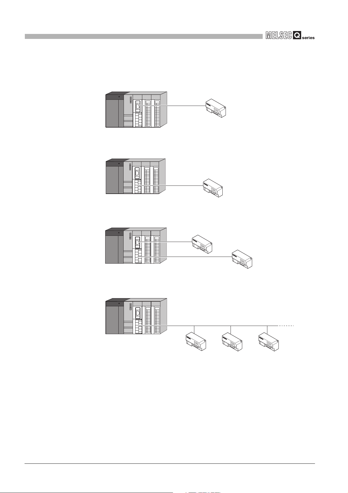
1
D300
D299
400499
D300
400500
D301
400501
1234H
Device memory
Device
Programmable
controller CPU
No sequence
program required
MODBUS device assignment parameter
QJ71MB91 (Slave function)
MODBUS device
RS-232, RS-422 or RS-485
Request message (Write 1234H to holding
register 400500)
MODBUS
Master device
OVERVIEW
(2) Supporting the slave function of MODBUS communication
The QJ71MB91 supports the slave function of the MODBUS communication, which is
an open network system for factory automation, and thereby is compatible with
various MODBUS master devices (hereinafter referred to as master) of other
manufacturers.
The slave function includes the following two functions.
(a) Automatic response function
The QJ71MB91 can automatically respond to a request message received from
the master.
Any sequence program for the slave function is not needed.
(b) MODBUS device assignment function
Using MODBUS device assignment parameters, the MODBUS devices are
correlated with the programmable controller CPU device memory.
This enables direct access from the master to the programmable controller CPU
device memory.
Supporting the MODBUS devices of large capacity, the QJ71MB91 allows all
device memories of the programmable controller CPU to be assigned.
1
2
3
4
OVERVIEW
SYSTEM
CONFIGURATION
SPECIFICATIONS
Figure 1.3 MODBUS device assignment function
MODBUS STANDARD
5
6
PRE-OPERATIONAL
PROCEDURES AND
7
8
FUNCTIONS
FUNCTION
SETTINGS
PARAMETER SETTING
1.1 Features
UTILITY PACKAGE
(GX Configurator-MB)
1 - 3
Page 22
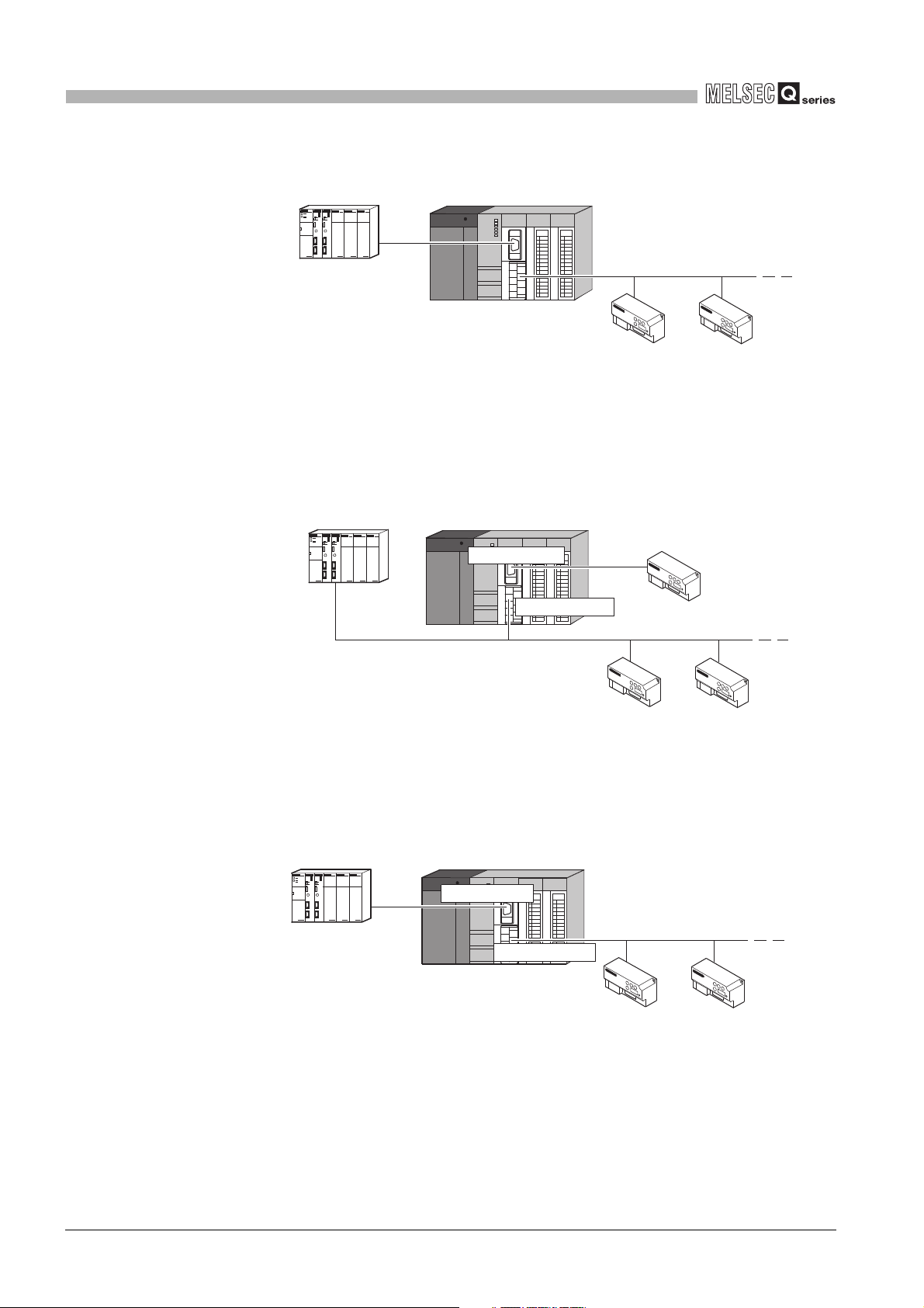
1
OVERVIEW
(3) Link operation function
The master connected to the CH1 side (RS-232) can communicate with multiple
slaves connected to the CH2 side (RS-422/485) via the QJ71MB91.
This function allows the MODBUS master device with RS-232 interface (for one-onone communication) to communicate with multiple MODBUS slave devices.
The request message/response message
can be relayed between channel 1 and 2.
Request
message
RS-232
Response
Message
MODBUS master device
(Third party programmable
controller)
RS-485
Response
Message
Request
message
MODBUS slave device
(Third party remote I/O, etc)
Figure 1.4 Communication using the link operation function
MODBUS slave device
(Third party sensor, etc)
(4) Supporting high-speed communication of 115200 bps.
The total transmission speed of up to 115200bps is available for Channel 1 and 2.
(5) Easy setting by GX Configurator-MB
GX Configurator-MB, which is separately available, allows easy configuration of the
QJ71MB91.
It can reduce programing steps for sequence programs, and the setting and operating
states of each module can be checked easily.
Therefore, GX Configurator-MB is recommended to be used for the QJ71MB91.
By setting various parameters in GX Configurator-MB, the QJ71MB91 can
communicate without creating sequence programs.
1 - 4
1.1 Features
Page 23

2
Remark
SYSTEM CONFIGURATION
CHAPTER2 SYSTEM CONFIGURATION
This chapter explains the system configuration of the QJ71MB91.
1
OVERVIEW
2.1 Applicable Systems
This section describes the applicable systems.
(1) Applicable modules and base units, and number of mountable modules
(a) When mounted with a CPU module
Refer to the user’s manual of the CPU module used.
Observe the following:
• A shortage of the power capacity may result depending on the combination of
mounted modules or the number of mounted modules. When mounting
modules, consider the power capacity. If the power is insufficient, change the
combination of modules.
• Mount modules so that the total number of I/O points does not exceed the
point range of the CPU module. Modules can be mounted in any slot within
the applicable range.
When mounted with a C Controller module, refer to the user’s manual of the C
Controller module used.
2
SYSTEM
CONFIGURATION
3
SPECIFICATIONS
4
MODBUS STANDARD
FUNCTIONS
5
(b) When mounted on a MELSECNET/H remote I/O station
Refer to the following.
Q Corresponding MELSECNET/H Network System Reference Manual
(Remote I/O network)
(c) When mounted on an RQ extension base unit
Refer to the following.
MELSEC iQ-R Module Configuration Manual
(2) Support of the multiple CPU system
Please refer to the following manual before using the QJ71MB91 in the multiple CPU
system.
QCPU User's Manual (Multiple CPU System)
FUNCTION
6
PRE-OPERATIONAL
PROCEDURES AND
SETTINGS
7
PARAMETER SETTING
8
2.1 Applicable Systems
UTILITY PACKAGE
(GX Configurator-MB)
2 - 1
Page 24

2
SYSTEM CONFIGURATION
(3) Supported software package
Relation between the system containing the QJ71MB91 and software package is
shown in the following table.
GX Developer or GX Works2 is required to start up the system in which the
QJ71MB91 is used.
Table2.1 Supported software package
Software version
Item
GX Developer GX Configurator-MB GX Works2
Q00J/Q00/Q01CPU
Q02/Q02H/Q06H/
Q12H/Q25HCPU
Q02PH/Q06PHCPU
Q12PH/Q25PHCPU
Q12PRH/Q25PRHCPU Redundant system
Q00UJ/Q00U/Q01UCPU
Q02U/Q03UD/
Q04UDH/Q06UDHCPU
Q10UDH/Q20UDHCPU
Q13UDH/Q26UDHCPU
Single CPU system Version 7 or later
Multiple CPU system Version 8 or later
Single CPU system Version 4 or later
Multiple CPU system Version 6 or later
Single CPU system
Multiple CPU system
Single CPU system
Multiple CPU system
Single CPU system
Multiple CPU system
Single CPU system
Multiple CPU system
Single CPU system
Multiple CPU system
Single CPU system
Multiple CPU system
Version 8.68W or later
Version 7.10L or later
Version 8.18U or later
Version 8.76E or later
Version 8.48A or later
Version 8.76E or later
Version 8.62Q or later
Version 1.05F or later
*1
Refer to the GX Works2
Version 1 Operating
Manual (Common).
Version 1.08J or later
Q03UDE/Q04UDEH/Q06UDEH/
Q13UDEH/Q26UDEHCPU
Q10UDEH/Q20UDEHCPU
CPU module other than those
listed above
When mounted to MELSECNET/H remote I/O station Version 6.01B or later Version 1.05F or later
2 - 2
2.1 Applicable Systems
Single CPU system
Version 8.68W or later
Multiple CPU system
Single CPU system
Version 8.76E or later
Multiple CPU system
Single CPU system
N/A N/A
Multiple CPU system
* 1 To use an extension base unit, use 8.45X or later.
Page 25

2
SYSTEM CONFIGURATION
2.2 Network Configuration
The following shows MODBUS network configuration examples using the QJ71MB91.
Master/Slave Line Used
Table2.2 Network configuration using QJ71MB91
QJ71MB91
System Configuration Reference
1
OVERVIEW
2
Master
Slave
Master/Slave
RS-232
RS-422/485 This section (1) (b)
RS-232, RS-422/485 This section (1) (c)
RS-485 1:n This section (1) (d)
RS-232
RS-422/485 This section (2) (b)
RS-232, RS-422/485 This section (2) (c)
RS-485 1:n This section (2) (d)
RS-232, RS-485
(with link operation
function)
RS-232 (Master),
RS-485 (Slave)
RS-232 (Slave)
RS-485 (Master)
1:1
1:1
1:n This section (2) (e)
1:n
This section (1) (a)
This section (2) (a)
This section (3) (a)
This section (3) (b)
SYSTEM
CONFIGURATION
3
SPECIFICATIONS
4
MODBUS STANDARD
FUNCTIONS
5
2.2 Network Configuration
FUNCTION
6
PRE-OPERATIONAL
PROCEDURES AND
SETTINGS
7
PARAMETER SETTING
8
UTILITY PACKAGE
(GX Configurator-MB)
2 - 3
Page 26
2
RS-232
QJ71MB91 (Master function)
MODBUS slave device
RS-485
QJ71MB91 (Master function)
MODBUS
slave device
MODBUS
slave device
MODBUS
slave device
SYSTEM CONFIGURATION
(1) Using the QJ71MB91 as a master station
(a) Connecting to a slave station (1:1) with a RS-232 line
Figure 2.1 Connecting to a slave station (1:1) with a RS-232 line
(b) Connecting to a slave station (1:1) with a RS-422/485 line
QJ71MB91 (Master function)
MODBUS slave device
RS-422/485
Figure 2.2 Connecting to a slave station with a RS-422/485 line
(c) Connecting to slave stations (1:1) with RS-232 and RS-422/485 lines
QJ71MB91 (Master function)
MODBUS slave device
RS-232
MODBUS slave device
RS-422/485
Figure 2.3 Connecting to slave stations (1:1) with RS-232 and RS-422/485 lines
(d) Connecting to slave stations (1:n)
2 - 4
2.2 Network Configuration
Figure 2.4 Connecting to slave stations (1:n)
Page 27

2
RS-232
MODBUS master device
MODBUS master device
RS-422/485
QJ71MB91 (Slave function)
*1
SYSTEM CONFIGURATION
1
(2) Using the QJ71MB91 as a slave station
(a) Connecting to a master station (1:1) with a RS-232 line
MODBUS master device
RS-232
Figure 2.5 Connecting to a master station (1:1) with a RS-232 line
QJ71MB91 (Slave function)
(b) Connecting to a master station (1:1) with a RS-422/485 line
QJ71MB91 (Slave function)
MODBUS master device
RS-422/485
Figure 2.6 Connecting to a master station (1:1) with a RS-422/485 line
(c) Connecting to master stations (1:1) with RS-232 and RS-422/485 lines
OVERVIEW
2
SYSTEM
CONFIGURATION
3
SPECIFICATIONS
4
MODBUS STANDARD
FUNCTIONS
Figure 2.7 Connecting to master stations with RS-232 and RS-422/485 lines
* 1 The same station number is used for both RS-232 and RS-422/485 interfaces.
(d) Connecting to a master station (1:n)
MODBUS master device
RS-485
MODBUS
slave device
QJ71MB91 (Slave function)
Figure 2.8 Connecting to a master station (1:n)
MODBUS slave
device
5
FUNCTION
6
PRE-OPERATIONAL
PROCEDURES AND
SETTINGS
7
PARAMETER SETTING
8
UTILITY PACKAGE
(GX Configurator-MB)
2.2 Network Configuration
2 - 5
Page 28
2
RS-485
RS-232
MODBUS master device QJ71MB91 (Slave function)
MODBUS
slave device
MODBUS
slave device
QJ71MB91
RS-485
RS-232
MODBUS
MODBUS master device
(Master function)
(Slave function)
slave device
MODBUS
slave device
MODBUS
slave device
MODBUS master device
MODBUS
slave device
MODBUS
slave device
RS-232
QJ71MB91
(Slave function)
(Master function)
RS-485
SYSTEM CONFIGURATION
(e) Connecting to a master station (1:n) with the link operation function
Figure 2.9 Connecting to a master station (1:n) with the link operation function
(3) Connecting master and slave stations separately through each interface
(a) Using the RS-232 interface as the master station and the RS-422/485 interface as
the slave station
Figure 2.10 Using the RS-232 interface as the master station and the RS-422/485
(b) Using the RS-232 interface as the slave station and the RS-422/485 interface as
the master station
Figure 2.11 Using the RS-232 interface as the slave station and the RS-422/485 interface
interface as the slave station
as the master station
2 - 6
2.2 Network Configuration
Page 29

2
SYSTEM CONFIGURATION
2.3 Precautions for System Configuration
(1) When used with a Redundant CPU
For precautions, refer to the following.
QnPRHCPU User's Manual (Redundant System)
(2) When used with a C Controller module
For precautions, refer to the following.
User’s manual of the C Controller module used
1
2
3
OVERVIEW
SYSTEM
CONFIGURATION
SPECIFICATIONS
4
MODBUS STANDARD
5
6
PRE-OPERATIONAL
PROCEDURES AND
7
FUNCTIONS
FUNCTION
SETTINGS
2.3 Precautions for System Configuration
PARAMETER SETTING
8
UTILITY PACKAGE
(GX Configurator-MB)
2 - 7
Page 30
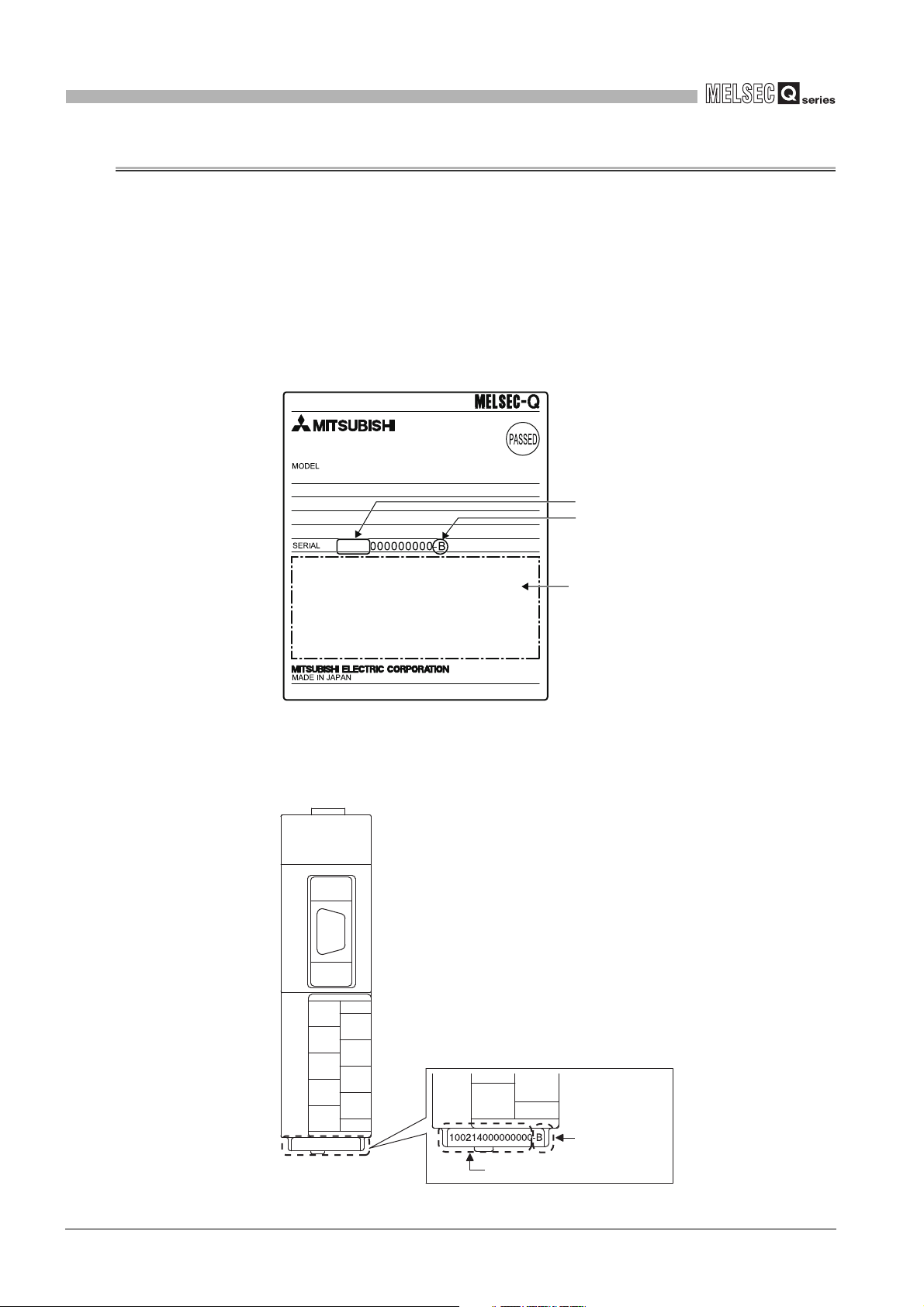
2
10021
Relevant regulation standards
Function version
Serial number (first five digits)
Serial No.
Function version
SYSTEM CONFIGURATION
2.4 How to Check the Function Version/Software Version
Check the function version and serial No. of the QJ71MB91and the GX Configurator-MB
software version by the following methods.
(1) Checking the version and serial No. of the QJ71MB91 functions
The serial No. and function version of the QJ71MB91 can be confirmed on the rating
plate and GX Developer's system monitor.
(a) Confirming the serial number on the rating plate
The rating plate is situated on the side face of the QJ71MB91.
Figure 2.12 Rating plate
(b) Checking on the front of the module
The serial No. and function version on the rating plate are also indicated on the
front of the module (lower part).
2 - 8
2.4 How to Check the Function Version/Software Version
Figure 2.13 Front face of QJ71MB91
Page 31

2
POINT
SYSTEM CONFIGURATION
1
(c) Confirming the serial number on the system monitor (Product Information List)
To display the system monitor, select [Diagnostics] [System monitor]
Product Inf. List
1) Production number display
Since the QJ71MB91 does not support the production number display, "-" is
displayed.
button of GX Developer.
Function version
Serial No. Production number
Figure 2.14 Product information list
OVERVIEW
2
SYSTEM
CONFIGURATION
3
SPECIFICATIONS
4
MODBUS STANDARD
FUNCTIONS
5
The serial No. displayed in the Product Information List of GX Developer may be
different from the one on the rating plate and the front of the module.
• The serial No. on the rating plate and the front of the module indicates the
management information of the product.
• The serial No. in the Product Information List of GX Developer indicates
the functional information on the product, which is updated when a new
function is added.
2.4 How to Check the Function Version/Software Version
2 - 9
FUNCTION
6
PRE-OPERATIONAL
PROCEDURES AND
SETTINGS
7
PARAMETER SETTING
8
UTILITY PACKAGE
(GX Configurator-MB)
Page 32

2
Software version
SYSTEM CONFIGURATION
(2) Checking the software version of GX Configurator-MB
The software version of GX Configurator-MB can be checked GX Developer’s
"Product information" screen.
[Operating Procedure]
GX Developer [Help] [Product information]
Figure 2.15 Product information
2 - 10
2.4 How to Check the Function Version/Software Version
Page 33

3
SPECIFICATIONS
CHAPTER3 SPECIFICATIONS
This chapter explains the performance specifications of the QJ71MB91, interface
specifications, I/O signals for communications with programmable controller CPU, and
buffer memory.
Please refer to the following manual for general specifications.
QCPU User's Manual (Hardware Design, Maintenance and Inspection)
3.1 Performance Specifications
1
2
OVERVIEW
SYSTEM
CONFIGURATION
Transmission
specifications
This section provides the performance specifications of QJ71MB91.
Table3.1 Performance specifications
Item Specifications Reference
Number of interfaces
Transmission speed Section 6.6
Transmission
distance
(Overall distance)
Automatic
communication
function
RS-232 Max. 15m (49.2 ft.) -
RS-422/485 Max. 1200m (4592.4 ft.) (Overall distance) -
Number of slaves
Function (for send) 7 functions Section 7.2.1
Input area size 4k words
Output area size 4k words
*1
RS-232 1 channel, RS-422/485 1 channel
300 600 1200 2400
4800 9600 14400 19200
28800 38400 57600 115200 (bps)
Communication is available with total transmission
speed of two interfaces within 115200bps.
32 per channel -
-
Section 3.5.1
3
SPECIFICATIONS
4
MODBUS STANDARD
FUNCTIONS
5
FUNCTION
6
Master
function
Communication
by dedicated
instructions
(MBRW, MBREQ)
Number of instructions that
can be executed
concurrently
Function (for send)
Input area size Max. 253 bytes per instruction
Output area size Max. 253 bytes per instruction
*2
MBREQ instruction: 19 functions
1 per channel
MBRW instruction: 9 functions
(Continued on next page)
3.1 Performance Specifications
CHAPTER 10
3 - 1
PRE-OPERATIONAL
PROCEDURES AND
SETTINGS
7
PARAMETER SETTING
8
UTILITY PACKAGE
(GX Configurator-MB)
Page 34

3
SPECIFICATIONS
Table3.1 Performance specifications (Continued)
Item Specifications Reference
Automatic
response function
MODBUS Device
Slave function
Number of occupied I/O points 32 points -
5VDC internal current consumption 0.31A -
External dimensions
Weight 0.20kg -
size
No. of simultaneously acceptable request
messages
Station No. 1 to 247 Section 6.6
Function (for receive) 17 functions CHAPTER 4
Coil 64k points
Input 64k points
Input register 64k points
Holding register 64k points
Extended file register Max. 4086k points
1 request per channel -
98 (3.86 in.) (H) 27.4 (1.08 in.) (W) 90 (3.54 in.)
(D) [mm]
* 1 Indicates the maximum number of slaves that can be communication targets.
* 2 Indicates the maximum number of dedicated instructions that can be executed simultaneously from
a sequence program.
Section 7.3.1
Appendix 4
3 - 2
3.1 Performance Specifications
Page 35

3
SPECIFICATIONS
3.2 RS-232 Interface Specification
This section explains RS-232 interface specifications.
3.2.1 RS-232 connector specification
This section provides the specifications of RS-232 connector that is connected to a target
device.
1
OVERVIEW
2
Pin
number
1
2 RD (RXD) Reception data
Signal code Signal name
(Use
prohibited)
(Use
prohibited)
QJ71MB91 Target device
Signal direction
-
3
SYSTEM
CONFIGURATION
1
2
3
4
6
7
8
9
5
3SD (TXD)
4
5 SG (GND) Signal ground
6
*1
7
*1
8
9
(Use
prohibited)
(Use
prohibited)
-
-
(Use
prohibited)
Transmission
data
(Use
prohibited)
(Use
prohibited)
Output for
cable
disconnection
detection
Input for cable
disconnection
detection
(Use
prohibited)
SPECIFICATIONS
-
-
4
MODBUS STANDARD
FUNCTIONS
5
FUNCTION
-
6
Figure 3.1 RS-232 connector specification
* 1 Connect Pin 8 to Pin 7.
Without connecting Pin 7 and 8, Pin 8 turns off and the CS signal may turn off (error code: 7403
(1) Descriptions of control signals
The following explains control signals. (The pin number of the connector is indicated
within the brackets.)
(a) RD signal (2)
Signal for receiving data.
(b) SD signal (3)
Signal for sending data.
3.2 RS-232 Interface Specification
3.2.1 RS-232 connector specification
H).
3 - 3
PRE-OPERATIONAL
PROCEDURES AND
SETTINGS
7
PARAMETER SETTING
8
UTILITY PACKAGE
(GX Configurator-MB)
Page 36

3
SPECIFICATIONS
(2) ON/OFF status of each signal
The ON and OFF statuses of a signal are indicated below.
(Output side) (Input side)
ON ......................... 5V to 15VDC, 3V to 15VDC
OFF ......................... -5V to -15VDC, -3V to -15VDC
(3) Interface connector
For QJ71MB91 RS-232 interface connector, use a 9-pin D sub (female) screw type
connector.
Use metric screws.
3 - 4
3.2 RS-232 Interface Specification
3.2.1 RS-232 connector specification
Page 37

3
SPECIFICATIONS
3.2.2 RS-232 cable specification
The RS-232 cable should be based on RS-232 standards and used within 15m(49.2ft).
1
2
3
OVERVIEW
SYSTEM
CONFIGURATION
SPECIFICATIONS
4
MODBUS STANDARD
5
6
PRE-OPERATIONAL
PROCEDURES AND
7
FUNCTIONS
FUNCTION
SETTINGS
3.2 RS-232 Interface Specification
3.2.2 RS-232 cable specification
3 - 5
8
PARAMETER SETTING
UTILITY PACKAGE
(GX Configurator-MB)
Page 38

3
+
+
+
+
+
+
+
SG
SDA
SDB
RDA
RDB
(FG)
(FG)
SPECIFICATIONS
3.3 RS-422/485 Interface Specification
This section explains RS-422/485 interface specifications.
3.3.1 RS-422/485 terminal block specification
This section provides the specifications of RS-422/485 terminal block that is connected to
a target device.
Signal
code
SDA Transmission data (+)
SDB Transmission data (-)
RDA Reception data (+)
RDB Reception data (-)
SG Signal ground
FG Frame ground
FG Frame ground
Figure 3.2 RS-422/485 terminal block specifications
Signal name
(1) The following explains control signals.
(a) SDA, SDB signal
Signal for QJ71MB91 to send data to a target device
(b) RDA, RDB signal
Signal for QJ71MB91 to receive data from a target device
Signal direction
QJ71MB91 Target device
3 - 6
(2) Terminating resistor
Connect the terminating resistor according to Section 6.5.2.
3.3 RS-422/485 Interface Specification
3.3.1 RS-422/485 terminal block specification
Page 39

3
SPECIFICATIONS
1
3.3.2 RS-422/485 cable specification
This section explains the specifications of RS-422/485 cable.
(1) RS-422/485 cable to be used
The RS-422/485 cable should meet the following specifications and used within
1200m(4592.4ft).
(2) When making a 1:n connection
When connecting to multiple devices (1:n), ensure that the overall distance is within
1200 m(4592.4ft).
(3) RS-422/485 cable specifications
Table3.2 RS-422/485 cable specifications
Item Description
Cable type Shielded cable
Number of pairs 3P
Conductor resistance (20°C) 88.0/km or less
Insulation resistance 10000M•km or more
Dielectric withstand voltage 500VDC, 1 minute
Electrostatic capacitance (1 kHz) 60nF/km or less by an average
Characteristic impedance (100 kHz) 110±10
OVERVIEW
2
SYSTEM
CONFIGURATION
3
SPECIFICATIONS
4
MODBUS STANDARD
FUNCTIONS
5
Recommended conductor size
0.2 mm
2
to 0.75 mm
2
FUNCTION
6
PRE-OPERATIONAL
PROCEDURES AND
SETTINGS
7
PARAMETER SETTING
8
3.3 RS-422/485 Interface Specification
3.3.2 RS-422/485 cable specification
3 - 7
UTILITY PACKAGE
(GX Configurator-MB)
Page 40

3
POINT
Remark
+
-
Receive data
Target
device
Terminating
resistor
RDA
RDB
SPECIFICATIONS
3.3.3 Precautions when transferring data using RS-422/485 line
Note the following points when performing data communication with a target device
through the RS-422/485 interface of QJ71MB91.
For the target device side, pay attention to the following when sending/receiving data.
(1) Preventive measures against faulty data reception on the target device
side
If the target device receives error data, install a pull-up or pull-down resistor to the
target device as shown below.
Installing a pull-up or pull-down resistor (resistance value: approx. 4.7 k , 1/4 W) can
prevent the reception of error data.
Figure 3.3 Preventive measures against faulty data reception
Error data will not be received if a pull-up or pull-down resistor is connected on the
target device side.
The case where any pull-up or pull-down resistor is not connected on the target
device is described below.
When any station is not performing transmission, the transmission line is in a high
impedance status and the line status is not stable due to noises, and the target
device may receive error data.
In such a case, parity or framing error may have occurred. Skip data reading for
error data.
3 - 8
3.3 RS-422/485 Interface Specification
3.3.3 Precautions when transferring data using RS-422/485 line
Page 41

3
Data
Data
(Output control input)
(Output control input)
Target device side
QJ71MB91 side
Outputs a mark with
2 characters or more
Data transmission
time range
H/W gate OFF time
(Refer to explanation above)
OFF time range of
output control input
(High impedance status)
QJ71MB91 can receive data.
ON time range of output
control input
(Low impedance status)
QJ71MB91 can send data.
SPECIFICATIONS
(2) RS-422/485 interface operation
(a) RS-422/485 interface configuration
For RS-422/485 interface, the configuration of driver (send)/receiver (receive)
component of the QJ71MB91 is as shown in the following diagram.
SDR
SDB
Output Control Input (*
RDA
RDB
Figure 3.4 RS-422/485 interface configuration
* 1 The "output control input" (also referred to as send gate) of the driver (send) component
determines whether to output data externally from SDA, SDB.
Driver
Receiver
Send data
Receive data
1
OVERVIEW
2
1
)
SYSTEM
CONFIGURATION
3
(b) RS-422/485 interface operation
When the "output control input" in the above figure is ON, the impedance status is
low (data transmittable).
In addition, when the "output control input" is OFF, the impedance status is high
(data not transmitted).
(c) QJ71MB91 transmission start timing, transmission process complete timing
• Transmission start timing
After releasing the high impedance status indicated in above (a) and (b), and
outputting two or more character data during data transmission, output the
actual data.
• Transmission process complete timing
Data transmission time for data of 1 bit or less is required as the H/W gate
OFF time to complete the transmission process (high impedance status) after
finishing data transmission.
(Transmission speed set in the QJ71MB91 is targeted.)
4
MODBUS STANDARD
5
6
PRE-OPERATIONAL
PROCEDURES AND
SPECIFICATIONS
FUNCTIONS
FUNCTION
SETTINGS
3.3.3 Precautions when transferring data using RS-422/485 line
Figure 3.5 Transmission process complete timing
3.3 RS-422/485 Interface Specification
3 - 9
7
8
PARAMETER SETTING
UTILITY PACKAGE
(GX Configurator-MB)
Page 42

3
SPECIFICATIONS
3.4 I/O Signals for Programmable Controller CPU
This section explains the I/O signals for the programmable controller CPU of QJ71MB91.
3.4.1 I/O signal list
This section explains the I/O signals for the QJ71MB91.
The following I/O signal assignment is based on the case where the start I/O No. of the
QJ71MB91 is "0000" (installed to slot 0 of the main base unit).
Device X represents an input signal from the QJ71MB91 to the programmable controller
CPU.
Device Y means an output signal from the programmable controller CPU to the
QJ71MB91.
The I/O signals for programmable controller CPU are listed below.
Refer to the reference sections for the details of each signal.
Table3.3 I/O signal list
Signal direction QJ71MB91 Programmable controller CPU Signal direction Programmable controller CPU QJ71MB91
Device No. Signal name Reference Device No. Signal name Reference
Module READY
X0
X1
X2 Y2
X3 Y3
X4
X5
X6
ON : Accessible
OFF : Inaccessible
Use prohibited -
CH1 Automatic communication
parameter setting, normally completed
ON : Normally completed
OFF : -
CH1 Automatic communication
parameter setting, error completed
ON : Error completed
OFF : -
CH1 Automatic communication
operation status
ON : Operating
OFF : Stopped
*1
Section
11. 1
Section
5.2.1,
9.1.1
Y0
Y1
Y4
Y5 Use prohibited -
Y6
Use prohibited -
CH1 Automatic communication parameter
setting request/automatic communication
start request
ON : Being requested
OFF : Not requested
CH1 Automatic communication stop
request
ON : Being requested
OFF : Not requested
Section
5.2.1,
9.1.1
Section
5.2.1
X7
3 - 10
CH1 Automatic communication error
status
ON : Error occurred
OFF : No error
* 1 Turns ON when the QJ71MB91 is ready after the programmable controller is turned from OFF to
ON or after the programmable controller CPU is reset.
Section
5.2.1
3.4 I/O Signals for Programmable Controller CPU
3.4.1 I/O signal list
Y7 Use prohibited -
(Continued on next page)
Page 43

3
Signal direction QJ71MB91 Programmable controller CPU Signal direction Programmable controller CPU QJ71MB91
SPECIFICATIONS
Table3.3 I/O signal list (Continued)
1
Device No. Signal name Reference Device No. Signal name Reference
MODBUS device assignment
X8
X9
XA
XB Use prohibited - YB
XC
XD
parameter setting, normally completed
ON : Normally completed
OFF : -
MODBUS device assignment
parameter setting, error completed
ON : Error completed
OFF : -
MODBUS device assignment
parameter setting existence
ON : Parameters set
OFF: No parameters set
CH2 Automatic communication
parameter setting, normally completed
ON : Normally completed
OFF : -
CH2 Automatic communication
parameter setting, error completed
ON : Error completed
OFF : -
Section
9.1.2
Section
5.2.1,
9.1.1
Y8
Y9
YA
YC
YD Use prohibited -
MODBUS device assignment parameter
setting request
ON : Being requested
OFF : Not requested
Use prohibited -
CH2 Automatic communication parameter
setting request/automatic communication
start request
ON : Being requested
OFF : Not requested
Section
9.1.2
Section
5.2.1,
9.1.1
OVERVIEW
2
SYSTEM
CONFIGURATION
3
SPECIFICATIONS
4
MODBUS STANDARD
FUNCTIONS
5
XE
XF
CH2 Automatic communication
operation status
ON : Operating
OFF : Stopped
CH2 Automatic communication error
status
ON : Error occurred
OFF : No error
Section
5.2.1
CH2 Automatic communication stop request
YE
YF Use prohibited -
ON : Being requested
OFF : Not requested
Section
5.2.1
(Continued on next page)
FUNCTION
6
PRE-OPERATIONAL
PROCEDURES AND
SETTINGS
7
PARAMETER SETTING
8
3.4 I/O Signals for Programmable Controller CPU
3.4.1 I/O signal list
3 - 11
UTILITY PACKAGE
(GX Configurator-MB)
Page 44

3
POINT
Signal direction QJ71MB91 Programmable controller CPU Signal direction Programmable controller CPU QJ71MB91
Device No. Signal name Reference Device No. Signal name Reference
SPECIFICATIONS
Intelligent function module switch
X10
setting change status
ON : Setting being changed
OFF : Setting not changed
Table3.3 I/O signal list (Continued)
Section
10.4
Y10
X11
X12 - Y12
X13 - Y13
X14 - Y14
X15 - Y15
X16 - Y16
X17 - Y17
X18 - Y18
X19 - Y19
X1A - Y1A
X1B
X1C
Use prohibited
CH Common/CH1 Error
ON : Error occurred
OFF : No error
CH2 Error
ON : Error occurred
OFF : No error
- Y11
Y1B
Section
11. 2
Y1C
Use prohibited -
CH Common/CH1 Error clear request
ON : Being requested
OFF : Not requested
CH2 Error clear request
ON : Being requested
OFF : Not requested
Section
11. 5
X1D
Use prohibited -
X1E Y1E
X1F
Watch dog timer error
ON : Module error occurred
OFF : Module operating normally
Section
11. 1
Y1D
Y1F
Do not output (turn ON) any "Use prohibited" signal among I/O signals for
programmable controller CPU.
Doing so may cause the programmable controller system to malfunction.
Use prohibited -
3 - 12
3.4 I/O Signals for Programmable Controller CPU
3.4.1 I/O signal list
Page 45

3
SPECIFICATIONS
3.5 Applications and Assignment of Buffer Memory
3.5.1 Buffer memory list
The buffer memory list is shown below.
Table3.4 Buffer memory list
1
OVERVIEW
2
Address Application Name
0000H to 0001
(0 to 1)
0002H
(2)
0003H
(3)
0004
H
(4)
0005H
(5)
0006H
(6)
0007
H
(7)
0008
H
(8)
0009H
(9)
000A
H
(10)
000B
H
(11)
H
System area (use prohibited) - - - -
CH1 side error response code storage area 0
System area (use prohibited) - - - -
Error code
Status
storage
area
Setting
area
Detailed
LED status
Detailed
LED clear
request
Setting
error status
read device
CH2 side error response code storage area 0
System area (use prohibited) - - - -
CH1 side detailed LED status storage area 0
CH2 side detailed LED status storage area 0
CH1 side detailed LED clear request storage
area
CH2 side detailed LED clear request storage
area
Device code F000
Head device number 0
Initial
value
0
0
Read/
Write
(*1)
H R
R
H
H R
R
H
R/W
H
H R/W
R/W
H
R/W
H
Initial
setting
(*2)
Reference
Section
11. 4.2
Section
11. 4.2
Section
11. 2
Section
11. 5
Section
7.3.4
SYSTEM
CONFIGURATION
3
SPECIFICATIONS
4
MODBUS STANDARD
FUNCTIONS
5
FUNCTION
6
000CH
(12)
System area (use prohibited) - - - -
* 1 Indicates whether the reading (Read)/writing (Write) from the sequence program is enabled or
disabled.
R: Readable W: Writable
* 2 Indicates whether setting on GX Configurator-MB is enabled or disabled.
: Setting enabled : Setting disabled
(Continued on next page)
3.5 Applications and Assignment of Buffer Memory
3.5.1 Buffer memory list
3 - 13
PRE-OPERATIONAL
PROCEDURES AND
SETTINGS
7
PARAMETER SETTING
8
UTILITY PACKAGE
(GX Configurator-MB)
Page 46

3
SPECIFICATIONS
Table3.4 Buffer memory list (Continued)
Address Application Name
000DH
(13)
000E
H
(14)
000F
H
(15)
0010H to 01FFH
(16 to 511)
0200H to 0201
(512 to 513)
0202
H
(514)
0203H
(515)
0204
H
(516)
Setting area
System area (use prohibited) - - - -
H
CPU response monitoring timer value
Set time = set value 500ms
Access target (when mounted to
MELSECNET/H remote I/O station)
Allocated error status area 0
Setting parameter existence 0
Target station No. 1
Request interval timer value
Set time = set value 10ms
Response monitoring timer value/Broadcast
delay value
Set time = set value 10ms
Initial
value
A
Read/
Write
H R/W
0
H
H
H
H
0
H R/W
0
H
(*1)
R/W
R/W
R/W
R/W
R/W
Initial
setting
(*2)
Reference
Section
7.3.6
Section
7.3.5
Section
7.3.4
0205
(517)
0206
(518)
0207H
(519)
0208
(520)
0209
(521)
020AH
(522)
020B
(523)
H
Automatic
H
communication
parameter
H
H
H
CH1 Automatic
communication
parameter 1
Type specification of the target MODBUS
device
Head buffer memory address 0000
Read
setting
Target MODBUS device head
number
Access points 0
Head buffer memory address 0000
Write
setting
Target MODBUS device head
number
Access points 0
0000
H
H
0
H R/W
H
H
0
H R/W
H
R/W
R/W
R/W
R/W
R/W
Section 7.2
* 1 Indicates whether the reading (Read)/writing (Write) from the sequence program is enabled or
disabled.
R: Readable W: Writable
* 2 Indicates whether setting on GX Configurator-MB is enabled or disabled.
: Setting enabled : Setting disabled
(Continued on next page)
3 - 14
3.5 Applications and Assignment of Buffer Memory
3.5.1 Buffer memory list
Page 47

3
SPECIFICATIONS
1
Table3.4 Buffer memory list (Continued)
Address Application Name
CH1 Automatic
020CH to 037F
(524 to 895)
0380H to 04FFH
(896 to 1279)
0500H to 08FF
(1280 to 2303)
0900
H
(2304)
0901H
(2305)
0902
H
(2306)
0903
H
(2307)
H
Automatic
communication
parameter
H
System area (use prohibited) - - - -
MODBUS
device
assignment
parameter
communication
parameter 2 to
32
CH2 Automatic
communication
parameter 1 to
32
Coil
assignment 1
(Same as CH1 Automatic communication parameter 1)
(Same as CH1 Automatic communication parameter 1)
Device code 0
Head device number 0
Head coil number 0
Assignment points 0
Initial
value
Read/
Write
(*1)
R/W
H
H R/W
R/W
H
R/W
H
Initial
setting
(*2)
Reference
Section
7.2
Section
7.3.1
OVERVIEW
2
SYSTEM
CONFIGURATION
3
SPECIFICATIONS
4
MODBUS STANDARD
FUNCTIONS
0904H to 093FH
(2308 to 2367)
Coil
assignment 2
to 16
* 1 Indicates whether the reading (Read)/writing (Write) from the sequence program is enabled or
disabled.
R: Readable W: Writable
* 2 Indicates whether setting on GX Configurator-MB is enabled or disabled.
: Setting enabled : Setting disabled
(Same as in Coil assignment 1)
(Continued on next page)
5
FUNCTION
6
PRE-OPERATIONAL
PROCEDURES AND
SETTINGS
7
PARAMETER SETTING
8
3.5 Applications and Assignment of Buffer Memory
3.5.1 Buffer memory list
3 - 15
UTILITY PACKAGE
(GX Configurator-MB)
Page 48

3
SPECIFICATIONS
Table3.4 Buffer memory list (Continued)
Address Application Name
0940
H
(2368)
0941
H
(2369)
0942H
(2370)
0943H
(2371)
0944H to 097F
(2372 to 2431)
0980H
(2432)
0981H
(2433)
0982
H
(2434)
H
MODBUS
device
assignment
parameter
Input
assignment
1
Input
assignment
2 to 16
Input
register
assignment
1
Device code 0
Head device number 0
Head input number 0
Assignment points 0
(Same as input assignment 1)
Device code 0
Head device number 0
Head input register number 0
Initial
value
Read/
Write
(*1)
R/W
H
R/W
H
H R/W
H R/W
H R/W
H R/W
R/W
H
Initial
setting
(*2)
Reference
Section
7.3.1
0983
H
(2435)
0984H to 09BFH
(2436 to 2495)
Assignment points 0
Input
register
assignment
2 to 16
* 1 Indicates whether the reading (Read)/writing (Write) from the sequence program is enabled or
* 2 Indicates whether setting on GX Configurator-MB is enabled or disabled.
(Same as in input register assignment 1)
disabled.
R: Readable W: Writable
: Setting enabled : Setting disabled
R/W
H
(Continued on next page)
3 - 16
3.5 Applications and Assignment of Buffer Memory
3.5.1 Buffer memory list
Page 49

3
09C0
(2496)
09C1
(2497)
09C2
(2498)
09C3
(2499)
09C4H to 09FF
(2500 to 2559)
SPECIFICATIONS
Table3.4 Buffer memory list (Continued)
Address Application Name
H
H
H
H
MODBUS
device
assignment
parameter
H
Holding
register
assignment
1
Holding
register
assignment
2 to 16
Device code 0
Head device number 0
Head holding register number 0
Assignment points 0
(Same as in holding register assignment 1)
Initial
value
H
H
H
H
Read/
Write
(*1)
R/W
R/W
R/W
R/W
Initial
setting
(*2)
Reference
Section
7.3.1
1
2
3
OVERVIEW
SYSTEM
CONFIGURATION
0A00H to 0BFF
(2560 to 3071)
0C00
H
(3072)
0C01
H
(3073)
0C02
H
(3074)
0C03
H
(3075)
0C04
H
(3076)
0C05
H
(3077)
0C06
H
(3078)
0C07
H
(3079)
0C08
H
(3080)
0C09
H
(3081)
H
System area (use prohibited) - - - -
R
R
H
R
Setting
status
Operating
status
Intelligent
function
module
switch
setting
status
Module
status
Intelligent
function
module
switch
operating
status
Switch 1: CH1 operation mode setting status
Switch 2: CH1 transmission setting status R
Switch 3: CH2 operation mode setting status R
Switch 4: CH2 transmission setting status R
Switch 5: CH1/CH2 Station No. setting status R
LED ON status 0
Switch 1: CH1 operation mode status
Switch 2: CH1 transmission status R
Switch 3: CH2 operation mode status R
Switch 4: CH2 transmission status R
Intelligent
function
module
switch
status
Intelligent
function
module
switch
status
Section
6.6, 11.2
Section
6.3, 11.2
Section
10.4
4
MODBUS STANDARD
5
6
PRE-OPERATIONAL
PROCEDURES AND
7
SPECIFICATIONS
FUNCTIONS
FUNCTION
SETTINGS
0C0A
H
(3082)
0C0BH to 0C12
(3083 to 3090)
Switch 5: CH1/CH2 Station No. status R
H
System area (use prohibited) - - - -
* 1 Indicates whether the reading (Read)/writing (Write) from the sequence program is enabled or
disabled.
R: Readable W: Writable
* 2 Indicates whether setting on GX Configurator-MB is enabled or disabled.
: Setting enabled : Setting disabled
PARAMETER SETTING
8
(Continued on next page)
UTILITY PACKAGE
(GX Configurator-MB)
3.5 Applications and Assignment of Buffer Memory
3.5.1 Buffer memory list
3 - 17
Page 50

3
SPECIFICATIONS
Table3.4 Buffer memory list (Continued)
Address Application Name
0C13
H
(3091)
0C14
H
(3092)
0C15H
(3093)
0C16
H
(3094)
0C17
H
(3095)
0C18H
(3096)
0C19
H
(3097)
0C1AH to 0C1F
(3098 to 3103)
H
Operating
status
Parameter
error
information
System area (use prohibited) - - - -
MODBUS device assignment parameter error
code storage area
MODBUS
device
assignment
parameter
setting result
storage area
CH1 Automatic communication parameter error
code storage area
CH1 Automatic communication parameter setting
result storage area
CH2 Automatic communication parameter error
code storage area
CH2 Automatic communication parameter setting
result storage area
Error, device type 0
Error, assigned group No. 0
Initial
value
0
H
H
H R
0
H
0
H
0
H R
0
H
Read/
Write
(*1)
R
R
R
R
R
Initial
setting
(*2)
Reference
Section
11. 4.1
* 1 Indicates whether the reading (Read)/writing (Write) from the sequence program is enabled or
disabled.
R: Readable W: Writable
* 2 Indicates whether setting on GX Configurator-MB is enabled or disabled.
: Setting enabled : Setting disabled
(Continued on next page)
3 - 18
3.5 Applications and Assignment of Buffer Memory
3.5.1 Buffer memory list
Page 51

3
SPECIFICATIONS
1
Table3.4 Buffer memory list (Continued)
Address Application Name
0C20H to 0C21
(3104 to 3105)
0C22H to 0C23H
(3106 to 3107)
0C24H to 0C27
(3108 to 3111)
0C28H to 0C47
(3112 to 3143)
0C48H to 0C67H
(3144 to 3175)
0C68H to 0CA7
(3176 to 3239)
0CA8H to 0CA9
(3240 to 3241)
0CAAH to 0CABH
(3242 to 3243)
H
H
H
H
H
Operating
status
Communication
condition
monitor area
CH1 Automatic communication operation
status storage area
(Parameters 1 to 32)
CH2 Automatic communication operation
status storage area
(Parameters 1 to 32)
System area (use prohibited) - - - -
CH1 Automatic communication error code
storage area
(Parameters 1 to 32)
CH2 Automatic communication error code
storage area
(Parameters 1 to 32)
System area (use prohibited) - - - -
CH1 Automatic communication setting status
storage area
(Parameters 1 to 32)
CH2 Automatic communication setting status
storage area
(Parameters 1 to 32)
Initial
value
0
0
0
0
0
0
Read/
Write
(*1)
H
H R
H
H R
H
H R
Initial
setting
(*2)
Reference
OVERVIEW
2
R
Section
11. 4.1
SYSTEM
CONFIGURATION
3
R
Section
11. 4.1
SPECIFICATIONS
4
R
Section
11. 4.1
MODBUS STANDARD
FUNCTIONS
5
0CACH to 0CAF
(3244 to 3247)
0CB0H to 0CB1
(3248 to 3249)
0CB2H to 0CB3H
(3250 to 3251)
0CB4H to 0CFD
(3252 to 3325)
H
H
H
System area (use prohibited) - - - -
* 1 Indicates whether the reading (Read)/writing (Write) from the sequence program is enabled or
disabled.
R: Readable W: Writable
* 2 Indicates whether setting on GX Configurator-MB is enabled or disabled.
System area (use prohibited) - - - -
CH1 Automatic communication ready status
storage area
(Parameters 1 to 32)
CH2 Automatic communication ready status
storage area
(Parameters 1 to 32)
: Setting enabled : Setting disabled
0
R-
H
0
H R-
(Continued on next page)
3.5 Applications and Assignment of Buffer Memory
3.5.1 Buffer memory list
Section
9.2.3
3 - 19
FUNCTION
6
PRE-OPERATIONAL
PROCEDURES AND
SETTINGS
7
PARAMETER SETTING
8
UTILITY PACKAGE
(GX Configurator-MB)
Page 52

3
SPECIFICATIONS
Table3.4 Buffer memory list (Continued)
Address Application Name
0CFE
H
(3326)
0CFF
H
(3327)
0D00H
(3328)
0D01
H
(3329)
0D02
H
(3330)
0D03H
(3331)
0D04
H
(3332)
0D05H to 0D06
(3333 to 3334)
H
Operating
status
Error log
Number of errors occurred 0
Error log write pointer 0
Detailed error code 0
Exception code 0
Function code 0
Error log 1
CH 0
Station No. 0
System area (use prohibited) - - - -
Initial
value
Read/
Write
(*1)
H
H
H R
H
H
H R
H
Initial
setting
R
R
R
R
R
Reference
(*2)
Section
11. 4.1
0D07H
(3335)
0D08H to 0DFFH
(3336 to 3583)
0E00H to 0EFF
(3584 to 3839)
Function 0
Error log
2 to 32
H
System area (use prohibited) - - - -
* 1 Indicates whether the reading (Read)/writing (Write) from the sequence program is enabled or
disabled.
R: Readable W: Writable
* 2 Indicates whether setting on GX Configurator-MB is enabled or disabled.
: Setting enabled : Setting disabled
(Same as Error log 1)
H R
(Continued on next page)
Section
11. 4.1
Section
11. 4.1
3 - 20
3.5 Applications and Assignment of Buffer Memory
3.5.1 Buffer memory list
Page 53

3
SPECIFICATIONS
1
Table3.4 Buffer memory list (Continued)
Address Application Name
0F00
(3840)
0F01H
(3841)
0F02
(3842)
0F03
(3843)
0F04H
(3844)
0F05
(3845)
0F06
(3846)
0F07H
(3847)
H
H
H
H
H
Communication
status
CH1
Communication
status
Diagnostic
data for
Master/Slave
Bus message count 0
Bus communication error count 0
Character overrun error count 0
Message discard count 0
Data discard count 0
Failed transmission count 0
Slave message count 0
Slave no-response count 0
Initial
value
Read/
Write
(*1)
H
H R
H
H
H R
H
H
H R
Initial
setting
R
R
R
R
R
(*2)
Reference
Section
11. 3
2
3
4
OVERVIEW
SYSTEM
CONFIGURATION
SPECIFICATIONS
0F08
(3848)
0F09
(3849)
0F0AH
(3850)
0F0B
(3851)
0F0C
(3852)
0F0DH
(3853)
H
H
Diagnostic
data for Slave
H
Slave NAK count 0
Slave busy count 0
Exception error count 0
Communications event count 0
H
H
H R
H
R
MODBUS STANDARD
FUNCTIONS
5
R
R
Section
4.12
FUNCTION
6
H
* 1 Indicates whether the reading (Read)/writing (Write) from the sequence program is enabled or
disabled.
R: Readable W: Writable
* 2 Indicates whether setting on GX Configurator-MB is enabled or disabled.
: Setting enabled : Setting disabled
2nd byte of end code 0A
Communications mode 0
H
H R
R
(Continued on next page)
Section
4.11.4
Section
4.11.5
PRE-OPERATIONAL
PROCEDURES AND
SETTINGS
7
PARAMETER SETTING
3.5 Applications and Assignment of Buffer Memory
3.5.1 Buffer memory list
3 - 21
8
UTILITY PACKAGE
(GX Configurator-MB)
Page 54

3
SPECIFICATIONS
Table3.4 Buffer memory list (Continued)
Address Application Name
0F0E
H
(3854)
0F0FH
(3855)
0F10
(3856)
0F11
(3857)
H
H
CH1
Diagnostic data
for Master
Communication
0F12H
status
(3858)
Communication
0F13H to 0F1E
(3859 to 3870)
0F1F
H
(3871)
H
status
System area (use prohibited) - - - -
Communication
event log (for
0F20H to 0F3FH
Slave)
(3872 to 3903)
Initial
value
Received exception error
count
No-response count 0
Broadcast count 0
Received NAK count 0
Received busy count 0
Communications event log
count
Communications event log
1 to 64
0
H
H R
H
H
H R
0
H
0
H R
Read/
Write
(*1)
R
R
R
R
Initial
setting
(*2)
Reference
Section
11. 3
Section
4.13
0F40H to 0F7F
(3904 to 3967)
0F80H to 0FFD
(3968 to 4093)
0FFEH
(4094)
0FFF
H
(4095)
H
H
Unit test result
CH2
Communication
status
(Same as CH1 communication status)
Section
4.13
System area (use prohibited) - - - -
Hardware test result 0
Self-loopback test result 0
H R
H
R
Section
6.4.1
Section
6.4.2
* 1 Indicates whether the reading (Read)/writing (Write) from the sequence program is enabled or
disabled.
R: Readable W: Writable
* 2 Indicates whether setting on GX Configurator-MB is enabled or disabled.
: Setting enabled : Setting disabled
(Continued on next page)
3 - 22
3.5 Applications and Assignment of Buffer Memory
3.5.1 Buffer memory list
Page 55

3
SPECIFICATIONS
1
Table3.4 Buffer memory list (Continued)
Address Application Name
1000H to 1FFF
(4096 to 8191)
2000H to 2FFFH
(8192 to
12287)
3000H to 3FFF
(12288 to
16383)
4000H to 4FFF
(16384 to
20479)
5000H to 5FFFH
(20480 to
24575)
H
Automatic
communication function
H
buffer
H
User free area 0H R/W
* 1 Indicates whether the reading (Read)/writing (Write) from the sequence program is enabled or
* 2 Indicates whether setting on GX Configurator-MB is enabled or disabled.
CH1 Automatic communication function buffer input
area
CH2 Automatic communication function buffer input
area
CH1 Automatic communication function buffer output
area
CH2 Automatic communication function buffer output
area
disabled.
R: Readable W: Writable
: Setting enabled : Setting disabled
Initial
value
0
H
0
H R
0
H
0
H
Read/
Write
(*1)
R
R/W
R/W
Initial
setting
(*2)
Reference
Section
5.2.1
Section
7.3.3
OVERVIEW
2
SYSTEM
CONFIGURATION
3
SPECIFICATIONS
4
MODBUS STANDARD
FUNCTIONS
5
FUNCTION
6
PRE-OPERATIONAL
PROCEDURES AND
SETTINGS
7
PARAMETER SETTING
8
3.5 Applications and Assignment of Buffer Memory
3.5.1 Buffer memory list
3 - 23
UTILITY PACKAGE
(GX Configurator-MB)
Page 56

4
MODBUS STANDARD FUNCTIONS
CHAPTER4 MODBUS STANDARD FUNCTIONS
This chapter explains the MODBUS standard functions supported by the QJ71MB91.
Using the MODBUS standard functions allows you to read/write to programmable
controller CPU devices and to load the QJ71MB91 status into the master.
4.1 MODBUS Standard Function Support List
(1) MODBUS standard function support list
The following table indicates a list of the MODBUS standard functions supported by
the QJ71MB91.
Table4.1 MODBUS standard function support list
Function
code
(Sub code)
01 - Read coils
02 - Read discrete inputs
03 - Read holding registers
04 - Read input registers
05 - Write single coil Writes a value (ON/OFF) to one coil. 1 point
06 - Write single register Writes a value to one holding register. 1 point
07 - Read exception status Reads error status. -
Sub-function
code
Function Description
Reads the status (ON/OFF) of one or
more coils.
Reads the status (ON/OFF) of one or
more inputs.
Reads the values of one or more
holding registers.
Reads the values of one or more input
registers.
Accessible
devices
per
message
1 to
2000 points
1 to
2000 points
1 to
125 points
1 to
125 points
Broadcast Reference
(Continued on next page)
Section
4.4
Section
4.5
Section
4.6
Section
4.7
Section
4.8
Section
4.9
Section
4.10
4 - 1
4.1 MODBUS Standard Function Support List
Page 57

4
MODBUS STANDARD FUNCTIONS
1
Table4.1 MODBUS standard function support list (continued)
Function
code
(Sub code)
08
Sub-function
code
00 Return query data
01
02
03
04 Force listen only mode
10
Function Description
Restart communications
option
Return diagnostic
register
Change ASCII input
delimiter
Clear counters and
diagnostic register
Returns the contents of the request
message without change.
Used to check if the network or the
target device is operating normally.
(Loopback test)
Initializes the communication port of the
receiving channel side and restarts the
slave function. (Clears counters such
as the message count.)
Returns to the online mode when it is in
the listen only mode.
Reads out the detailed LED status of
the QJ71MB91 to the master.
Changes the 2nd byte (LF(0A
end code in the ASCII mode to a
specified data.
Places a slave into the offline mode.
Used when disconnecting a slave from
the network.
Clears counters (e.g. message count).
Also, clears the diagnostic register and
the error of the channel where the
request message has been received.
H)) of the
Accessible
devices
per
message
-
-
-
-
-
-
Broadcast Reference
Section
4.11.1
Section
4.11.2
Section
4.11.3
Section
4.11.4
Section
4.11.5
Section
4.11.6
OVERVIEW
2
SYSTEM
CONFIGURATION
3
SPECIFICATIONS
4
MODBUS STANDARD
FUNCTIONS
5
11
12
13
14
15
Return bus message
count
Return bus
communication error
count
Return bus exception
error count
Return slave message
count
Return slave no
response count
Reads out the number of messages
detected on the line to the master.
Reads out the number of error
messages detected on the line to the
master.
Reads out the frequency of exception
errors to the master.
Reads out the number of the slave
message processing to the master.
(Including reception of broadcast
request messages)
Reads out the number of broadcast
request messages received to the
master.
-
-
-
-
-
Section
4.11.7
Section
4.11.8
Section
4.11.9
Section
4.11.10
Section
4.11.11
(Continued on next page)
FUNCTION
6
PRE-OPERATIONAL
PROCEDURES AND
SETTINGS
7
PARAMETER SETTING
8
4.1 MODBUS Standard Function Support List
UTILITY PACKAGE
(GX Configurator-MB)
4 - 2
Page 58

4
MODBUS STANDARD FUNCTIONS
Table4.1 MODBUS standard function support list (continued)
Function
code
(Sub code)
08
Sub-function
code
16 Return slave NAK count
17 Return slave busy count
18
19
20
Function Description
Return bus character
overrun count
Return IOP overrun
error count
Clear overrun counter
and flag
Reads out the number of NAK
responses to the master.
The QJ71MB91 always returns "0".
Reads out the number of busy
responses to the master.
The QJ71MB91 always returns "0".
To the master, reads out the number of
times the request message size
exceeds the upper limit.
Reads the IOP overrun error counter
value to the master.
The QJ71MB91 returns to the master
the number of times the request
message size exceeds the upper limit.
(Same as the Return bus character
overrun count)
Clears the overrun error counter and
flag.
The QJ71MB91 clears the character
overrun error counter value.
Accessible
devices per
message
-
-
-
-
-
Broadcast Reference
Section
4.11.12
Section
4.11.13
Section
4.11.14
Section
4.11.15
Section
4.11.16
11 -
12 -
15 - Write multiple coils
Get communications
event counter
Get communications
event log
Acquires the number of messages
whose requested processing (read/
write, diagnostics, etc.) have been
normally completed.
Whether the action corresponding to the
request message is normally completed
or not can be checked.
Acquires the communications event log
of the QJ71MB91 into the master.
Writes values (ON/OFF) to multiple
coils.
-
-
1 to
1968 points
(Continued on next page)
Section
4.12
Section
4.13
Section
4.14
4 - 3
4.1 MODBUS Standard Function Support List
Page 59

4
Remark
MODBUS STANDARD FUNCTIONS
1
Table 4.1 MODBUS standard function support list (continued)
Function
code
(Sub code)
16 - Write multiple registers
17 - Report slave ID
20(6) - Read file record
21(6) - Write file record
22 - Mask write register
23 -
*1
24
Sub-function
code
Read/Write multiple
registers
- Read FIFO queue
Function Description
Writes values to multiple holding
registers.
Acquires the information of the slave
(QJ71MB91) mounted station into the
master.
Reads values of one or more extended
file registers.
Writes values to one or more extended
file registers.
Masks the values stored in a single
holding register with AND or OR and
writes the value.
Reads from or writes to multiple holding
registers.
Reads values from the holding
registers in FIFO queue structure.
Accessible
devices per
message
1 to
123 points
-
1 to
124 points
1 to
122 points
1 point
Read:
1 to
125 points
Write:
1 to
121 points
---
Broadcast Reference
Section
4.15
Section
4.16
Section
4.17
Section
4.18
Section
4.19
Section
4.20
OVERVIEW
2
SYSTEM
CONFIGURATION
3
SPECIFICATIONS
4
MODBUS STANDARD
FUNCTIONS
5
43
*1
-
Read device
identification
* 1 The slave function of the QJ71MB91 does not support this function.
( This section (2))
Reads the module identification
information of the slave.
---
FUNCTION
6
The usable functions are limited when the QJ71MB91 is installed to a
MELSECNET/H remote I/O station.( This section (3))
PRE-OPERATIONAL
PROCEDURES AND
SETTINGS
7
PARAMETER SETTING
8
4.1 MODBUS Standard Function Support List
UTILITY PACKAGE
(GX Configurator-MB)
4 - 4
Page 60

4
MODBUS STANDARD FUNCTIONS
(2) Standard function support list for the master and slave functions
The following table indicates a standard function support list classified by the master
and slave functions of the QJ71MB91.
Table4.2 Standard function support list for the master and slave functions
Function
code
(Sub code)
01 - Read coils
02 - Read discrete inputs
03 - Read holding registers
04 - Read input registers
05 - Write single coil
06 - Write single register
07 - Read exception status
Sub-function
code
00 Return query data
01 Restart communications option
02 Return diagnostic register
Function
Automatic
communication
function
Master function
MBRW
instruction
MBREQ
instruction
Slave
function
*1
08
03 Change ASCII input delimiter
04 Force listen only mode
10 Clear counters and diagnostic register
11 Return bus message count
12 Return bus communication error count
13 Return bus exception error count
14 Return slave message count
15 Return slave no response count
16 Return slave NAK count
: Supported : Not supported
* 1 Since the MBREQ instruction allows users to create request message frames, function codes other
than the above can be also sent. ( Section 10.3)
(Continued on next page)
4 - 5
4.1 MODBUS Standard Function Support List
Page 61

4
Remark
MODBUS STANDARD FUNCTIONS
1
Table4.2 Standard function support list for the master and slave functions (Continued)
Function
code
(Sub code)
08
11 - Get communications event counter
12 - Get communications event log
15 - Write multiple coils
16 - Write multiple registers
17 - Report slave ID
20(6) - Read file record
Sub-function
code
17 Return slave busy count
18 Return bus character overrun count
19 Return IOP overrun error count
20 Clear overrun counter and flag
Function
Automatic
communication
function
Master function
MBRW
instruction
MBREQ
instruction
*1
Slave
function
2
3
4
OVERVIEW
SYSTEM
CONFIGURATION
SPECIFICATIONS
21(6) - Write file record
22 - Mask write register
23 - Read/Write multiple registers
24 - Read FIFO queue
43 - Read device identification
* 1 Since the MBREQ instruction allows users to create request message frames, function codes other
than the above can be also sent. ( Section 10.3)
The usable functions are limited when the QJ71MB91 is installed to a
MELSECNET/H remote I/O station.( This section (3))
: Supported : Not supported
5
6
PRE-OPERATIONAL
7
MODBUS STANDARD
FUNCTIONS
FUNCTION
PROCEDURES AND
SETTINGS
PARAMETER SETTING
4.1 MODBUS Standard Function Support List
8
UTILITY PACKAGE
(GX Configurator-MB)
4 - 6
Page 62

4
MODBUS STANDARD FUNCTIONS
(3) List of MODBUS standard functions supported when accessing a
MELSECNET/H remote I/O station
The following MODBUS standard functions are available when the QJ71MB91
mounted on a MELSECNET/H remote I/O station makes access to the MELSECNET/
H remote I/O station.
Table4.3 MODBUS standard function savailable for access to MELSECNET/H remote I/O station
Function
code
(Sub code)
01 - Read coils
02 - Read discrete inputs
03 - Read holding registers
04 - Read input registers
05 - Write single coil
06 - Write single register
07 - Read exception status
Sub-function
Code
* 1 The access target is the MELSECNET/H remote I/O station.
When the MELSECNET/H remote master station is the access target, available functions are the
same as those shown in (2).
* 2 Accessing the MODBUS device that is not supported by the MELSECNET/H remote I/O station
results in error completion. (Exception code: 04
If the access target is the MELSECNET/H remote master station, it can be assigned to the control
CPU device of the MELSECNET/H remote master station.
Function
Master function
Automatic
communication
function
MBRW
instruction
MBREQ
instruction
Slave function
*1
*2
*2
*2
*2
*2
*2
*2
: Supported : Supported with restrictions : Not supported
H)
4 - 7
(Continued on next page)
4.1 MODBUS Standard Function Support List
Page 63

4
MODBUS STANDARD FUNCTIONS
1
Table 4.3 MODBUS standard functions available for access to MELSECNET/H remote I/O station (continued)
Function
code
(Sub code)
08
Sub-function
code
00 Return query data
01 Restart communications option
02 Return diagnostic register
03 Change ASCII input delimiter
04 Force listen only mode
10
11 Return bus message count
12
13
Clear counters and diagnostic
register
Return bus communication
error count
Return bus exception error
count
Function
Automatic
communication
function
Master function
MBRW
instruction
MBREQ
instruction
Slave function
*1
OVERVIEW
2
SYSTEM
CONFIGURATION
3
SPECIFICATIONS
4
14 Return slave message count
15
16 Return slave NAK count
17 Return slave busy count
18
19 Return IOP overrun error count
20 Clear overrun counter and flag
Return slave no response
count
Return bus character overrun
count
* 1 The access target is the MELSECNET/H remote I/O station.
When the MELSECNET/H remote master station is the access target, available functions are the
same as those shown in (2).
* 2 Accessing the MODBUS device that is not supported by the MELSECNET/H remote I/O station
results in error completion. (Exception code: 04
If the access target is the MELSECNET/H remote master station, it can be assigned to the control
CPU device of the MELSECNET/H remote master station.
: Supported : Supported with restrictions : Not supported
H)
(Continued on next page)
5
6
PRE-OPERATIONAL
7
8
MODBUS STANDARD
FUNCTIONS
FUNCTION
PROCEDURES AND
SETTINGS
PARAMETER SETTING
4.1 MODBUS Standard Function Support List
UTILITY PACKAGE
(GX Configurator-MB)
4 - 8
Page 64

4
POINT
MODBUS STANDARD FUNCTIONS
Table 4.3 MODBUS standard functions available for access to MELSECNET/H remote I/O station (continued)
Function
code
(Sub code)
11 -
12 - Get communications event log
15 - Write multiple coils
16 - Write multiple registers
17 - Report slave ID
20(6) - Read file record
21(6) - Write file record
22 - Mask write register
23 - Read/Write multiple registers
24 - Read FIFO queue
Sub-function
code
Function
Get communications event
counter
Automatic
communication
function
Master function
MBRW
instruction
MBREQ
instruction
Slave function
*2
*2
*2
*2
*1
43 - Read device identification
* 1 The access target is the MELSECNET/H remote I/O station.
When the MELSECNET/H remote master station is the access target, available functions are the
same as those shown in (2).
* 2 Accessing the MODBUS device that is not supported by the MELSECNET/H remote I/O station
results in error completion. (Exception code: 04
If the access target is the MELSECNET/H remote master station, it can be assigned to the control
CPU device of the MELSECNET/H remote master station.
When the QJ71MB91 is mounted to a MELSECNET/H remote I/O station, switch
the access target using the Access target (when mounted to MELSECNET/H
remote I/O station) in the buffer memory (address: 000E
: Supported : Supported with restrictions : Not supported
)
H
H). ( Section 7.3.5)
4 - 9
4.1 MODBUS Standard Function Support List
Page 65

4
Remark
DataAddress field Function code Error check
MODBUS Protocol Data Section
Section 4.3 to Section 4.20
MODBUS STANDARD FUNCTIONS
4.2 Frame Specifications
The following shows the frame specifications for the MODBUS protocol.
1
OVERVIEW
2
Figure 4.1 Frame specifications
Address field
Function code
Data
Error check
Table4.4 Frame specifications
Area name Description
[When master sends a request message to slave]
0: Sends a request message to all the slaves. (Broadcast)
1 to 247: Stores the target slave station No.
[When slave sends a response message to master]
The host station number is stored when sending a response message.
[When master sends a request message to slave]
The master specifies the number of the action to be taken by the slave.
[When slave sends a response message to master]
A requested function code is stored in the case of normal completion.
The most significant bit turns ON in the case of error completion.
[When master sends a request message to slave]
The information needed to execute the action specified by a function code is stored.
[When slave sends a response message to master]
The execution result of the action specified by a function code is stored.
An exception code is stored when failed.
The master adds a check code in a request message and transmits the request message.
*1
The slave, which received the request message, recalculates the check code in the request
message and determines whether the message is correct or not.
The message is discarded if it has an error.
SYSTEM
CONFIGURATION
3
SPECIFICATIONS
4
MODBUS STANDARD
FUNCTIONS
5
FUNCTION
6
* 1 The error check method differs depending on the frame mode.( Section 4.2.1)
Refer to the following for the data size of each area.
Section 4.2.1
4.2 Frame Specifications
PRE-OPERATIONAL
PROCEDURES AND
SETTINGS
7
PARAMETER SETTING
8
UTILITY PACKAGE
(GX Configurator-MB)
4 - 10
Page 66

4
Remark
Data
Start
Address field
Function code
Error check
END
(Start)
Address field
3.5 character time
or more
1 byte 1 byte
0 to 252 bytes
2 bytes
3.5 character time
or more
1 byte
Error check calculation range
MODBUS STANDARD FUNCTIONS
4.2.1 Frame mode
For the QJ71MB91, the following frame modes are available.
The frame mode of the QJ71MB91 must be consistent with that of the target device.
(1) Available frame modes
(a) RTU mode
In this mode, frames are received or sent in binary codes.
The frame specifications are compliant with the MODBUS protocol specifications.
Figure 4.2 Frame in RTU mode
The error check in the RTU mode is conducted by CRC (Cyclic Redundancy
Check).
The QJ71MB91 calculates the CRC by the following steps.
Please follow the same steps to calculate the CRC when conducting an error
check on the target device.
1) Load the register whose 16 bits are all "1".
2) The CRC is calculated every 8 bits from the upper bit of the frame.
Calculate the 8 bits of the frame and the exclusive logical sum (XOR) of the
bits in the above 1).
3) Shift the result of 2) by 1 bit to the right.
4) If the least significant bit of the above 2) is "1", calculate the exclusive OR
(XOR) from the result in 3) and the generator polynomial (A001
H).
If the least significant bit is "0", do not calculate the exclusive OR (XOR), but
shift it by 1 bit to the right.
5) Repeat the above steps 3) and 4) until the bit is shifted up to 8 times.
6) Calculate the exclusive OR (XOR) from the result of 5) and the next 8 bits of
the frame.
7) Repeat steps 3) to 6).
4 - 11
4.2 Frame Specifications
4.2.1 Frame mode
8) Repeat the above operations until the end of the data unit is reached.
The final value is a calculated CRC value.
9) The CRC value is stored in the frame in the order from the lower 8 bits to the
upper 8 bits.
Page 67

4
MODBUS STANDARD FUNCTIONS
The following is a calculation example in the case where function code 07H is sent to
station No. 2.
CRC error check procedure 16-bit register (MSB) Flag
(Load the register whose 16 bits are all "1")
02
H(Station No.)
Exclusive OR (XOR)
Table4.5 CRC calculation procedures
1111
1111
1111
1111
1111
0000
1111
1111
0010
1101
1
OVERVIEW
2
Shift 1
Generator polynomial
Exclusive OR (XOR)
Shift2
Generator polynomial
Exclusive OR (XOR)
Shift3
Shift4
Generator polynomial
Exclusive OR (XOR)
Shift5
Shift6
Generator polynomial
Exclusive OR (XOR)
Shift7
Shift8
Generator polynomial
Exclusive OR (XOR)
07H(Function)
Exclusive OR (XOR) 1000 0001
Shift 1
Generator polynomial
Exclusive OR (XOR)
Shift2
Generator polynomial
Exclusive OR (XOR)
0111
1010
1101
0110
1010
1100
0110
0011
1010
1001
0100
0010
1010
1000
0100
0010
1010
1000
0100
1010
1110
0111
1010
1101
1111
0000
1111
1111
0000
1111
0111
0011
0000
0011
1001
0100
0000
0100
0010
0001
0000
0001
0000
0000
0000
0000
0000
0000
1111
0000
1111
1111
0000
1111
1111
1111
0000
1111
1111
1111
0000
1111
0111
0011
0000
0011
0000
0011
1001
0000
1001
0100
0000
0100
1110
0001
1111
1111
0001
1110
1111
1111
0001
1110
1111
1111
0001
1110
1111
1111
0001
1110
0111
1001
1100
0001
1101
1110
0001
1111
1
SYSTEM
1
CONFIGURATION
3
0
1
SPECIFICATIONS
0
1
0
1
4
MODBUS STANDARD
FUNCTIONS
5
1
FUNCTION
1
6
Shift3
Generator polynomial
Exclusive OR (XOR)
Shift4
Shift5
Generator polynomial
Exclusive OR (XOR)
Shift6
Shift7
Shift8
CRC value 12H 41H
0110
1010
1100
0110
0011
1010
1001
0100
0010
0001
1000
0000
1000
0100
0010
0000
0010
1001
0100
0010
0010
0000
0010
0001
0000
0000
0000
0000
1000
0100
4.2 Frame Specifications
4.2.1 Frame mode
0111
0001
0110
0011
1001
0001
1000
0100
0010
0001
1
0
1
0
0
0
4 - 12
PRE-OPERATIONAL
PROCEDURES AND
SETTINGS
7
PARAMETER SETTING
8
UTILITY PACKAGE
(GX Configurator-MB)
Page 68

4
Remark
MODBUS STANDARD FUNCTIONS
Address field
H) (07H)
(02
Figure 4.3 Frame for CRC calculation
Function code CRC (Error check)
(41H) (12H)
(b) ASCII mode
In this mode, frames are received or sent in units of 2 characters (2 bytes) in
ASCII codes.
The frame specifications are compliant with the MODBUS protocol specifications.
Start END
:
H)
(3A
Address field
2 characters
Function code
2 characters
Error check calculation range
Figure 4.4 Frame in ASCII mode
Data
n x 2 characters
(n = 0 to 252)
Error check
2 characters
CR + LF
(0DH) (0AH)
The error check in the ASCII mode is conducted by LRC (Longitudinal
Redundancy Check).
The QJ71MB91 calculates the LRC by the following steps.
Please follow the same steps to calculate the LRC when conducting an error
check on the target device.
1) To calculate the LRC, convert the ASCII codes within the error check range
into the RTU format (binary).
2) Add the figures in units of contiguous 8 bits in the frame. (Excluding carries
during addition.)
3) Change the result of the above 2) to a 2's complement. (Reverse the bits and
add 01
H.)
4) Convert the result of 3) to an ASCII code.
4 - 13
4.2 Frame Specifications
4.2.1 Frame mode
Page 69

4
Head input number Read points
Start
:
Address field
(02
H)
Function code
(01
H)
LRC
(Error check)
(F5
H)
3A
H 30H 32H 30H 31H
(00H) (00H) (00H) (08H)
30
H 30H 30H 30H 30H 30H 30H 38H 46H 35H 0DH
"CR" "LF"
0A
H
MODBUS STANDARD FUNCTIONS
The following are calculation examples in the case where function code 01H is
sent to station No. 2.
Table4.6 LRC calculation procedure (when sending a request message)
LRC in request message transmission
Station No. (address field)
Function code
Head coil number (H)
Head coil number(L)
Read points (H)
Read points (L)
02
01
00
00
00
08
0000
0000
0000
0000
0000
+0000
0010
0001
0000
0000
0000
1000
1
OVERVIEW
2
Addition result
Bit reversal 1
+1
2's complement
LRC (Error check) F5 F 5
Table4.7 LRC calculation procedure (when receiving a response message)
LRC in reception of a response message
Station No. (address field)
Function code
Head coil number(H)
Head coil number(L)
Read points (H)
Read points (L)
LRC (Error check)
Addition result 00 0000 0000
0B
F4
F5
02
01
00
00
00
08
F5
0000
0000
0000
0000
0000
0000
+1111
0000
1111
1111
0010
0001
0000
0000
0000
1000
0101
1011
0100
0101
SYSTEM
CONFIGURATION
3
1
SPECIFICATIONS
4
MODBUS STANDARD
FUNCTIONS
5
FUNCTION
Figure 4.5 Frame for LRC calculation
(2) Frame mode setting
The frame mode is set in the intelligent function module switch setting.
( Section 6.6)
4.2 Frame Specifications
4.2.1 Frame mode
4 - 14
6
PRE-OPERATIONAL
PROCEDURES AND
SETTINGS
7
PARAMETER SETTING
8
UTILITY PACKAGE
(GX Configurator-MB)
Page 70

4
MODBUS STANDARD FUNCTIONS
4.3 Protocol Data Unit Formats by Functions
This section describes MODBUS protocol data unit formats used in the QJ71MB91.
(1) Precautions
(a) Device number specified in messages
When specifying a device number in a message, specify it as "(Device number) 1".
However, this does not apply to the file and device numbers specified for reading/
writing the extended file register.
(Example) When reading input 32 (100032) with Read Discrete Inputs (FC: 02)
Function code
Function code
H
02
Specify 31 (001FH) for the head input number
to read the input 32 (100032) status.
Figure 4.6 Specifying the MODBUS device number
Head input number
001FH
(H)
Data
Read points
0001
H
(L) (L)
(H)
The device number to be stored in the response message is "(Device number of
actually read/written device) - 1".
(b) When the QJ71MB91 receives a broadcast request message
Although the processing (read/write, diagnostics, etc.) requested by the request
message is performed, no response message is sent to the master.
(c) When the QJ71MB91 receives a request message in the listen only mode
The request message is discarded except for a particular case.
To receive the request message, change it to the online mode.
( Section 4.11.5)
4 - 15
4.3 Protocol Data Unit Formats by Functions
Page 71

4
MODBUS STANDARD FUNCTIONS
(2) When the processing is completed in error at the slave (QJ71MB91)
When the processing (read/write, diagnostics, etc.) requested by the request
message is completed in error, an exception code is sent to the master.(
"Response message formats (when completed with an error)" in Section 4.4 to 4.20.)
(a) Storage location of exception code and error code
The exception code is also stored in the buffer memory of the QJ71MB91.
Furthermore, for identification of detailed causes, an error code is stored in the
QJ71MB91 buffer memory.
The exception code and error codes can be confirmed by the error log area of the
buffer memory (address: 0CFE
(3) How to see the request/response message formats provided in Section
4.4 to 4.20
(a) Request/Response message format diagram
The following shows how to see the request/response message format diagrams
provided in Section 4.4 to 4.20.
Area name
Function code
H to 0DFFH).( Section 11.4)
Data
1
2
3
4
OVERVIEW
SYSTEM
CONFIGURATION
SPECIFICATIONS
Frame contents
[For request message format]
Setting range
[For response message format]
Value stored to the
response message
Figure 4.7 Request/Response message format diagram
Function
code
H)
(01
1 byte (8 bits) 1 byte (8 bits)
Head coil number
(0000
(H)
H to FFFFH)
(L) (L)
When a single data is expressed
. . .
by 2 bytes, set the upper byte
(8 bits) as (H) and the lower byte
(8 bits) as (L).
Read points
H to 07D0H)
(0001
(H)
MODBUS STANDARD
5
6
PRE-OPERATIONAL
PROCEDURES AND
7
FUNCTIONS
FUNCTION
SETTINGS
4.3 Protocol Data Unit Formats by Functions
PARAMETER SETTING
8
UTILITY PACKAGE
(GX Configurator-MB)
4 - 16
Page 72

4
Data
(L)
Data
(L)
(L)(L)
Data
(L)
Read points
0
(30
H)
0
(30H)
3
(33H)
F
(46H)
(RTU mode)
Function code
Function
code
(01
H)
Head coil number
(006E
H)
Read points
(003FH)
Convert RTU mode to ASCII mode
(ASCII mode)
Function code
Function code
0
(30
H)
1
(31H)
Head coil number
0
(30
H)
0
(30H)
6
(36H)
E
(45
H)
(H)
(H)
(H)
(H) (H)
MODBUS STANDARD FUNCTIONS
(b) Frame mode of the message format
The message formats in Section 4.4 to 4.20 are based on the case in the RTU
mode.
For use in ASCII mode, convert the values into ASCII codes.
(Conversion example)
Figure 4.8 Conversion example from RTU mode to ASCII mode
(c) Response message format
The response message formats issued from the slave to the master differs
depending on whether the slave has normally completed or failed to handle the
requested processing (read/write, diagnostics, etc.)
The formats for normal and error completions are shown in Section 4.4 to 4.20.
4 - 17
4.3 Protocol Data Unit Formats by Functions
Page 73

4
Data
(L) (L)
Function code
Function
code
(01
H)
Head coil number
(0000
H to FFFFH)
Read points
(0001H to 07D0H)
(H)
(H)
Data
b0b1b2b3b4b5b6b7
Function code
Function
code
(01
H)
Number of
read bytes
n
Device data
1
Device data
n
(Number of read bytes n)
(Device data 1 to n)
Device data 1
Device data n
Bit device
storage order
0 : OFF
1 : ON
The read coil statuses are stored in order from low-order to high-order bits.
When the number of read points is not a multiple of 8, the excess bits turn to 0.
Data
Function code
(81
H)
Function code
Exception
code*
1
MODBUS STANDARD FUNCTIONS
4.4 Read Coils (FC: 01)
Reads the status (ON/OFF) of one or more coils.
(1) Request message format (Master Slave)
1
2
OVERVIEW
SYSTEM
CONFIGURATION
Figure 4.9 Read coils (Request message)
(2) Response message format (Slave Master)
(When completed normally)
3
SPECIFICATIONS
4
MODBUS STANDARD
FUNCTIONS
5
FUNCTION
6
(When completed with an error)
Figure 4.11 Read coils (Exception message)
* 1 Exception and error codes are stored in the buffer memory in the case of error completion.
Refer to the following for storage location, confirmation methods, and detailed contents.
Figure 4.10 Read coils (Normal response message)
Section 11.4
4.4 Read Coils (FC: 01)
PRE-OPERATIONAL
PROCEDURES AND
SETTINGS
7
PARAMETER SETTING
8
UTILITY PACKAGE
(GX Configurator-MB)
4 - 18
Page 74

4
Data
(L) (L)
Function code
Function
code
(02
H)
Head input number
(0000
H to FFFFH)
Read points
(0001H to 07D0H)
(H)
(H)
Data
b0b1b2b3b4b5b6b7
Function code
Function
code
(02
H)
Number of
read bytes
n
Device data
1
Device data
n
(Number of read bytes n)
(Device data 1 to n)
Device data 1
Device data n
Bit device
storage order
0 : OFF
1 : ON
The read input statuses are stored in order from low-order to high-order bits.
When the number of read points is not a multiple of 8, the excess bits turn to 0.
Data
Function code
Function
code
(82
H)
Exception
code*
1
MODBUS STANDARD FUNCTIONS
4.5 Read Discrete Inputs (FC: 02)
Reads the status (ON/OFF) of one or more inputs.
(1) Request message format (Master Slave)
Figure 4.12 Read discrete inputs (Request message)
(2) Response message format (Slave Master)
(When completed normally)
4 - 19
(When completed with an error)
Figure 4.14 Read discrete inputs (Exception message)
* 1 Exception and error codes are stored in the buffer memory in the case of error completion.
4.5 Read Discrete Inputs (FC: 02)
Figure 4.13 Read discrete inputs (Normal response message)
Refer to the following for storage location, confirmation methods, and detailed contents.
Section 11.4
Page 75

4
Data
(L) (L)
Function code
Function
code
(03
H)
Head holding register number
(0000
H to FFFFH)
Read points
(0001H to 007DH)
(H)
(H)
Data
. . .
(L) (L)
Function code
Function
code
(03
H)
Number of
read bytes
n x 2 *1
Device data
1
Device data
n
(Number of read bytes n x 2)
*1 For example, if n = 4, the number of read
bytes is calculated as 4 x 2 = 8 bytes.
(H) (H)
Data
Function code
Function
code
(83
H)
Exception
code *
2
MODBUS STANDARD FUNCTIONS
4.6 Read Holding Registers (FC: 03)
Reads the values of one or more holding registers.
(1) Request message format (Master Slave)
1
2
OVERVIEW
SYSTEM
CONFIGURATION
Figure 4.15 Read holding registers (Request message)
(2) Response message format (Slave Master)
(When completed normally)
Figure 4.16 Read holding registers (Normal response message)
(When completed with an error)
3
SPECIFICATIONS
4
MODBUS STANDARD
FUNCTIONS
5
FUNCTION
6
Figure 4.17 Read holding registers (Exception message)
* 2 Exception and error codes are stored in the buffer memory in the case of error completion.
Refer to the following for storage location, confirmation methods, and detailed contents.
Section 11.4
4.6 Read Holding Registers (FC: 03)
PRE-OPERATIONAL
PROCEDURES AND
SETTINGS
7
PARAMETER SETTING
8
UTILITY PACKAGE
(GX Configurator-MB)
4 - 20
Page 76

4
Data
(L) (L)
Function code
Function
code
(04
H)
Head input register number
(0000
H to FFFFH)
Read points
(0001H to 007DH)
(H) (H)
Data
Function code
Function
code
(84
H)
Exception
code *
2
MODBUS STANDARD FUNCTIONS
4.7 Read Input Registers (FC: 04)
Reads the values of one or more input registers.
(1) Request message format (Master Slave)
Figure 4.18 Read input registers (Request message)
(2) Response message format (Slave Master)
(When completed normally)
Function code
Function
code
H
)
(04
Number of
read bytes
1
n x 2 *
Figure 4.19 Read input registers (Normal response message)
Device data
1
(H)
Data
. . .
(L) (L)
(Number of read bytes n x 2)
*1 For example, if n = 4, the number of read
bytes is calculated as 4 x 2 = 8 bytes.
Device data
n
(H)
(When completed with an error)
Figure 4.20 Read input registers (Exception message)
* 2 Exception and error codes are stored in the buffer memory in the case of error completion.
Refer to the following for storage location, confirmation methods, and detailed contents.
Section 11.4
4 - 21
4.7 Read Input Registers (FC: 04)
Page 77

4
Data
(L) (L)
Function code
Function
code
(05
H)
Coil number
(0000
H to FFFFH)
ON/OFF specification
0000
H : OFF
FF00
H : ON
(H)
(H)
Data
Function code
Function
code
(85
H)
Exception
code*
1
MODBUS STANDARD FUNCTIONS
4.8 Write Single Coil (FC: 05)
Writes a value (ON/OFF) to one coil.
(1) Request message format (Master Slave)
1
2
OVERVIEW
SYSTEM
CONFIGURATION
Figure 4.21 Write single coil (Request message)
(2) Response message format (Slave Master)
(When completed normally)
The slave returns the request message received from the master without change.
(When completed with an error)
Figure 4.22 Write single coil (Exception message)
* 1 Exception and error codes are stored in the buffer memory in the case of error completion.
Refer to the following for storage location, confirmation methods, and detailed contents.
Section 11.4
3
SPECIFICATIONS
4
MODBUS STANDARD
FUNCTIONS
5
FUNCTION
6
4.8 Write Single Coil (FC: 05)
PRE-OPERATIONAL
PROCEDURES AND
SETTINGS
7
PARAMETER SETTING
8
UTILITY PACKAGE
(GX Configurator-MB)
4 - 22
Page 78

4
Data
(L) (L)
Function code
Function
code
(06
H)
Holding register number
(0000
H to FFFFH)
Write data
(0000H to FFFFH)
(H)
(H)
Data
Function code
Function
code
(86
H)
Exception
code*
1
MODBUS STANDARD FUNCTIONS
4.9 Write Single Register (FC: 06)
Writes a value to one holding register.
(1) Request message format (Master Slave)
Figure 4.23 Write single register (Request Message)
(2) Response message format (Slave Master)
(When completed normally)
The slave returns the request message received from the master without change.
(When completed with an error)
Figure 4.24 Write single register (Exception message)
* 1 Exception and error codes are stored in the buffer memory in the case of error completion.
Refer to the following for storage location, confirmation methods, and detailed contents.
Section 11.4
4 - 23
4.9 Write Single Register (FC: 06)
Page 79

4
Function code
Function code
(07
H)
Data
Function code
Function
code
(07
H)
Error
information *1
Data
Function code
Function
code
(87
H)
Exception
code *
2
MODBUS STANDARD FUNCTIONS
4.10 Read Exception Status (FC: 07)
Reads error status.
(1) Request message format (Master Slave)
1
2
OVERVIEW
SYSTEM
CONFIGURATION
Figure 4.25 Read exception status (Request message)
(2) Response message format (Slave Master)
(When completed normally)
Figure 4.26 Read exception status (Normal request message)
* 1 The data of the device specified in the Setting error status read device (address: 000AH to 000BH)
in the buffer memory are stored in the error information area. ( Section 7.3.4)
(When completed with an error)
3
SPECIFICATIONS
4
MODBUS STANDARD
FUNCTIONS
5
FUNCTION
6
Figure 4.27 Read exception status (Exception message)
* 2 Exception and error codes are stored in the buffer memory in the case of error completion.
Refer to the following for storage location, confirmation methods, and detailed contents.
Section 11.4
4.10 Read Exception Status (FC: 07)
4 - 24
PRE-OPERATIONAL
PROCEDURES AND
SETTINGS
7
PARAMETER SETTING
8
UTILITY PACKAGE
(GX Configurator-MB)
Page 80

4
(L)
Data
Function code
Function
code
(08
H)
Sub-function code
Sub-function code
(0000
H)
Arbitrary data
(H)
Data
Function code
Function
code
(88
H)
Exception
code*
1
MODBUS STANDARD FUNCTIONS
4.11 Diagnostics (FC: 08)
Executes the various diagnostics and checks the QJ71MB91 status and communication
status.
4.11.1 Return query data (sub-function code: 00)
Returns the contents of the request message without change.
Used to check if the network or the target device is operating normally. (Loopback test)
(1) Request message format (Master Slave)
Figure 4.28 Return query data (Request message)
(2) Response message format (Slave Master)
(When completed normally)
The slave returns the request message received from the master without change.
(When completed with an error)
Figure 4.29 Return query data (Exception message)
* 1 Exception and error codes are stored in the buffer memory in the case of error completion.
Refer to the following for storage location, confirmation methods, and detailed contents.
Section 11.4
4 - 25
4.11 Diagnostics (FC: 08)
4.11.1 Return query data (sub-function code: 00)
Page 81

4
MODBUS STANDARD FUNCTIONS
4.11.2 Restart communications option (sub-function code: 01)
Initializes the communication port of the receiving channel side and restarts the slave
function.
Restart is performed after returning the response message corresponding to a request
message.
The operation status returns to online mode when it was in the listen only mode.
The following data are cleared when executing the restart communications option.
• Data being received
• CH1/2 side error response code storage area in the buffer memory (address:
/0004H)
0002
H
• CH1/2 side detailed LED status storage area in the buffer memory (address:
/0007H)
0006
H
• Diagnostic counter ( Section 11.3)
• The ERR. LED OFF
• Communications event count ( Section 4.12)
• Communications event log ( Section 4.13)
*1
*1
*2
*3
1
2
3
4
OVERVIEW
SYSTEM
CONFIGURATION
SPECIFICATIONS
* 1 Clears only the receiving channel side area.
* 2 Clears the errors of the channel that has received the request message.
As the errors of other channels are not cleared, the LED will not turn off if an error has occurred on
any other channel.
* 3 Clears the data when the communications event log clear is specified in the request message.
MODBUS STANDARD
5
6
PRE-OPERATIONAL
PROCEDURES AND
7
FUNCTIONS
FUNCTION
SETTINGS
4.11 Diagnostics (FC: 08)
4.11.2 Restart communications option (sub-function code: 01)
4 - 26
8
PARAMETER SETTING
UTILITY PACKAGE
(GX Configurator-MB)
Page 82

4
(L)
Data
(L)
Function
code
(08
H)
Function code
Sub-function code
Sub-function code
(0001
H)
Clear setting of
Communications event log
0000
H: Not clear
FF00
H: Clear
(H)
(H)
Data
Function code
Function
code
(88
H)
Exception
code*
1
MODBUS STANDARD FUNCTIONS
(1) Request message format (Master Slave)
Figure 4.30 Restart communications option (Request message)
(2) Response message format (Slave Master)
(When completed normally)
The slave returns the request message received from the master without change.
However, if a request message is received during listen only mode, the status will only
return to online mode and no response message will be returned.
(When completed with an error)
Figure 4.31 Restart communications option (Exception message)
* 1 Exception and error codes are stored in the buffer memory in the case of error completion.
Refer to the following for storage location, confirmation methods, and detailed contents.
Section 11.4
4 - 27
4.11 Diagnostics (FC: 08)
4.11.2 Restart communications option (sub-function code: 01)
Page 83

4
Remark
(L)
Data
(L)
Function code
Function
code
(08
H)
Sub-function code
Sub-function code
(0002
H)
(0000
H)
(H) (H)
MODBUS STANDARD FUNCTIONS
1
4.11.3 Return diagnostic register (sub-function code: 02)
Reads out the detailed LED status of the QJ71MB91 to the master.
(1) Request message format (Master Slave)
Figure 4.32 Return diagnostic register (Request message)
(2) Response message format (Slave Master)
(When completed normally)
Function code
Function
code
H)
(08
Sub-function code
Sub-function code
(H)
(0002
H)
(L)
Diagnostic register
value
(H)
Data
(L)
OVERVIEW
2
SYSTEM
CONFIGURATION
3
SPECIFICATIONS
4
MODBUS STANDARD
FUNCTIONS
0 0 0 1/0 1/0 1/0 1/0 1/0 0 0 0 1/0 1/0 1/0 1/0 1/0
The QJ71MB91 stores the lower 8 bits of the buffer memory's
Detailed LED status as a diagnostic register. (address: 0006
Figure 4.33 Return diagnostic register (Normal response message)
b0b1b2b3b4b5b6b7b8b9b10b11b12b13b14b15
CH1 C/N
CH1 P/S
CH1 PRO.
CH1 SIO
CH1 ERR.
Unused (Fixed to 0)
CH2 C/N
CH2 P/S
CH2 PRO.
CH2 SIO
CH2 ERR.
Unused (Fixed to 0)
CH1 side Detailed
LED status
(0: OFF, 1: ON)
CH2 side Detailed
LED status
(0: OFF, 1: ON)
H/0007H)
5
FUNCTION
6
PRE-OPERATIONAL
PROCEDURES AND
SETTINGS
7
PARAMETER SETTING
8
Refer to the following for each items of the detailed LED status.
Section 11.2
4.11.3 Return diagnostic register (sub-function code: 02)
4.11 Diagnostics (FC: 08)
4 - 28
UTILITY PACKAGE
(GX Configurator-MB)
Page 84

4
Data
Function code
Function
code
(88
H)
Exception
code*
1
MODBUS STANDARD FUNCTIONS
(When completed with an error)
Figure 4.34 Return diagnostic register (Exception message)
* 1 Exception and error codes are stored in the buffer memory in the case of error completion.
Refer to the following for storage location, confirmation methods, and detailed contents.
Section 11.4
4 - 29
4.11 Diagnostics (FC: 08)
4.11.3 Return diagnostic register (sub-function code: 02)
Page 85

4
POINT
Start
END
Address field
2 characters
Function code
2 characters
Data
n x 2 characters
(n = 0 to 252)
Error check
2 characters
CR + LF
(0D
H) (0AH)
Change this into a specified data.
:
(3A
H)
(L)
Data
Function code
Function
code
(08
H)
Sub-function code
Sub-function code
(0003
H)
Input delimiter
setting
(00
H to FFH)
(00
H)
(H)
Data
Function code
Function
code
(88
H)
Exception
code*
1
MODBUS STANDARD FUNCTIONS
4.11.4 Change ASCII input delimiter (sub-function code: 03)
Changes the 2nd byte (LF(0AH)) of the end code in the ASCII mode to a specified data.
The specified data is stored in the 2nd byte of end code in the buffer memory. (address:
/0F4CH)
0F0C
H
Figure 4.35 Change part in the end code
(1) Request message format (Master Slave)
1
2
3
OVERVIEW
SYSTEM
CONFIGURATION
SPECIFICATIONS
Figure 4.36 Change ASCII input delimiter (Request message)
(2) Response message format (Slave Master)
(When completed normally)
The slave returns the request message received from the master without change.
(When completed with an error)
Figure 4.37 Change ASCII input delimiter (Exception message)
* 1 Exception and error codes are stored in the buffer memory in the case of error completion.
Refer to the following for storage location, confirmation methods, and detailed contents.
Section 11.4
4
MODBUS STANDARD
5
6
PRE-OPERATIONAL
PROCEDURES AND
7
FUNCTIONS
FUNCTION
SETTINGS
This function is used only for 1:1 connections.
Do not use this function for 1:n connections.
PARAMETER SETTING
8
4.11.4 Change ASCII input delimiter (sub-function code: 03)
4.11 Diagnostics (FC: 08)
4 - 30
UTILITY PACKAGE
(GX Configurator-MB)
Page 86

4
(L)
Data
(L)
Function code
Function
code
(08
H)
Sub-function code
Sub-function code
(0004
H)
(0000
H)
(H)
(H)
Data
Function code
Function
code
(88
H)
Exception
code*
1
MODBUS STANDARD FUNCTIONS
4.11.5 Force listen only mode (sub-function code: 04)
Places a slave into the offline mode.
Used when disconnecting a slave from the network.
When QJ71MB91 is set in the listen only mode, the status is as follows:
• Ignores all request messages except for those of restart communications
option.( Section 4.11.2)
• Stops counting of the diagnostic counter.( Section 11.3)
• Continues recording with the communications event log.( Section 4.13)
(1) Request message format (Master Slave)
Figure 4.38 Force listen only mode (Request message)
(2) Response message format (Slave Master)
(When completed normally)
No response message is returned because the listen only mode (offline status) is
active.
(When completed with an error)
Figure 4.39 Force listen only mode (Exception message)
* 1 Exception and error codes are stored in the buffer memory in the case of error completion.
Refer to the following for storage location, confirmation methods, and detailed contents.
Section 11.4
4 - 31
4.11 Diagnostics (FC: 08)
4.11.5 Force listen only mode (sub-function code: 04)
Page 87

4
POINT
MODBUS STANDARD FUNCTIONS
1. Whether the QJ71MB91 has been switched to listen only mode or not can be
checked in the Communications mode of the buffer memory (address: 0F0D
H).
0F4D
H: Online mode
0000
H: Listen only mode
0001
2. The listen only mode can be changed to online mode by either of the
following:
• Restart communications option ( Section 4.11.2)
• Power OFF ON, programmable controller CPU reset
1
H/
OVERVIEW
2
SYSTEM
CONFIGURATION
3
SPECIFICATIONS
4
MODBUS STANDARD
5
6
PRE-OPERATIONAL
PROCEDURES AND
7
FUNCTIONS
FUNCTION
SETTINGS
4.11 Diagnostics (FC: 08)
4.11.5 Force listen only mode (sub-function code: 04)
4 - 32
8
PARAMETER SETTING
UTILITY PACKAGE
(GX Configurator-MB)
Page 88

4
MODBUS STANDARD FUNCTIONS
4.11.6 Clear counters and diagnostic register (sub-function code: 10)
Clears counters (e.g. message count).
Also, clears the diagnostic register and the error of the channel where the request
message has been received.
The following counters will be cleared.( Section 11.3)
• Bus message count
• Bus communication error count
• Exception error count
• Slave message count
• Slave no-response count
• Slave NAK count
• Slave busy count
• Character overrun error count
• Communications event count ( Section 4.12)
The following diagnostic resisters will be cleared.
• CH1/2 side detailed LED status storage area of the buffer memory (address:
/0007H)
0006
H
• CH1/2 side error response code storage area of the buffer memory (address:
/0004H)
0002
H
* 1 Clears only the receiving channel side area.
*1
*1
4 - 33
4.11 Diagnostics (FC: 08)
4.11.6 Clear counters and diagnostic register (sub-function code: 10)
Page 89

4
(L)
Data
(L)
Function code
Function
code
(08
H)
Sub-function code
Sub-function code
(000A
H)
(0000
H)
(H) (H)
Data
Function code
Function
code
(88
H)
Exception
code*
1
MODBUS STANDARD FUNCTIONS
(1) Request message format (Master Slave)
Figure 4.40 Clear counters and diagnostic register (Request message)
(2) Response message format (Slave Master)
(When completed normally)
The slave returns the request message received from the master without change.
(When completed with an error)
1
2
3
OVERVIEW
SYSTEM
CONFIGURATION
SPECIFICATIONS
Figure 4.41 Clear counters and diagnostic register (Exception message)
* 1 Exception and error codes are stored in the buffer memory in the case of error completion.
Refer to the following for storage location, confirmation methods, and detailed contents.
Section 11.4
4
MODBUS STANDARD
5
6
PRE-OPERATIONAL
PROCEDURES AND
7
FUNCTIONS
FUNCTION
SETTINGS
4.11.6 Clear counters and diagnostic register (sub-function code: 10)
4.11 Diagnostics (FC: 08)
4 - 34
8
PARAMETER SETTING
UTILITY PACKAGE
(GX Configurator-MB)
Page 90

4
(L)
Function code
Function
code
(08
H)
Data
(L)
Sub-function code
Sub-function code
(000B
H)
(0000
H)
(H) (H)
(L)
Data
(L)
Function code
Function
code
(08
H)
Sub-function code
Sub-function code
(000B
H)
Bus message count value
(0000
H to FFFFH) *
1
The QJ71MB91 returns the bus message count value of the
buffer memory to the master. (address: 0F00
H/0F40H)
(H)
(H)
Data
Function code
Function
code
(88
H)
Exception
code *
2
MODBUS STANDARD FUNCTIONS
4.11.7 Return bus message count (sub-function code: 11)
Reads out the number of messages detected on the line to the master.
(1) Request message format (Master Slave)
Figure 4.42 Return bus message count (Request message)
(2) Response message format (Slave Master)
(When completed normally)
Figure 4.43 Return bus message count (Normal response message)
* 1 Refer to the following for the relevant counts, count clear methods and precautions.
Section 11.3
(When completed with an error)
Figure 4.44 Return bus message count (Exception message)
* 2 Exception and error codes are stored in the buffer memory in the case of error completion.
Refer to the following for storage location, confirmation methods, and detailed contents.
Section 11.4
4 - 35
4.11 Diagnostics (FC: 08)
4.11.7 Return bus message count (sub-function code: 11)
Page 91

4
(L)
Data
(L)
Function code
Function
code
(08
H)
Sub-function code
Sub-function code
(000C
H)
(0000
H)
(H)
(H)
(L)
Data
(L)
Function code
Function
code
(08
H)
Sub-function code
Sub-function code
(000C
H)
Bus communication
error count value
(0000
H to FFFFH) *
1
The QJ71MB91 returns the bus communication error count value
of the buffer memory to the master. (address: 0F01
H/0F41H)
(H)
(H)
Data
Function code
Function
code
(88
H)
Exception
code *
2
MODBUS STANDARD FUNCTIONS
1
4.11.8 Return bus communication error count (sub-function code: 12)
Reads out the number of error messages detected on the line to the master.
(1) Request message format (Master Slave)
Figure 4.45 Return bus communication error count (Request message)
(2) Response message format (Slave Master)
(When completed normally)
OVERVIEW
2
SYSTEM
CONFIGURATION
3
SPECIFICATIONS
4
MODBUS STANDARD
FUNCTIONS
Figure 4.46 Return bus communication error count (Normal response message)
* 1 Refer to the following for the relevant counts, count clear methods and precautions.
Section 11.3
(When completed with an error)
Figure 4.47 Return bus communication error count (Exception message)
* 2 Exception and error codes are stored in the buffer memory in the case of error completion.
Refer to the following for storage location, confirmation methods, and detailed contents.
Section 11.4
5
FUNCTION
6
PRE-OPERATIONAL
PROCEDURES AND
SETTINGS
7
PARAMETER SETTING
8
4.11.8 Return bus communication error count (sub-function code: 12)
4.11 Diagnostics (FC: 08)
4 - 36
UTILITY PACKAGE
(GX Configurator-MB)
Page 92

4
(L)
Data
(L)
Function code
Function
code
(08
H)
Sub-function code
Sub-function code
(000D
H)
(0000
H)
(H)
(H)
(L)
Data
(L)
Function code
Function
code
(08
H)
Sub-function code
Sub-function code
(000D
H)
Exception error count value
(0000
H to FFFFH) *
1
The QJ71MB91 returns the exception error count value of the
buffer memory to the master. (address: 0F0A
H/0F4AH)
(H)
(H)
Data
Function code
Function
code
(88
H)
Exception
code *
2
MODBUS STANDARD FUNCTIONS
4.11.9 Return bus exception error count (sub-function code: 13)
Reads out the frequency of exception errors to the master.
(1) Request message format (Master Slave)
Figure 4.48 Return bus exception error count (Request message)
(2) Response message format (Slave Master)
(When completed normally)
Figure 4.49 Return bus exception error count (Normal response message)
* 1 Refer to the following for the relevant counts, count clear methods and precautions.
Section 11.3
(When completed with an error)
Figure 4.50 Return bus exception error count (Exception message)
* 2 Exception and error codes are stored in the buffer memory in the case of error completion.
Refer to the following for storage location, confirmation methods, and detailed contents.
Section 11.4
4 - 37
4.11 Diagnostics (FC: 08)
4.11.9 Return bus exception error count (sub-function code: 13)
Page 93

4
(L)
Data
(L)
Function code
Function
code
(08
H)
Sub-function code
Sub-function code
(000E
H)
(0000
H)
(H)
(H)
(L)
Data
(L)
Function code
Function
code
(08
H)
Sub-function code
Sub-function code
(000E
H)
Slave message count value
(0000
H to FFFFH) *
1
The QJ71MB91 returns the slave message count value of the
buffer memory to the master. (address: 0F06
H/0F46H)
(H)
(H)
Data
Function code
Function
code
(88
H)
Exception
code *
2
MODBUS STANDARD FUNCTIONS
1
4.11.10 Return slave message count (sub-function code: 14)
Reads out the number of the slave message processing to the master. (Including receive
of request messages from broadcast.)
OVERVIEW
(1) Request message format (Master Slave)
Figure 4.51 Return slave message count (Request message)
(2) Response message format (Slave Master)
(When completed normally)
2
SYSTEM
CONFIGURATION
3
SPECIFICATIONS
4
MODBUS STANDARD
FUNCTIONS
5
Figure 4.52 Return slave message count (Normal response message)
* 1 Refer to the following for the relevant counts, count clear methods and precautions.
Section 11.3
(When completed with an error)
Figure 4.53 Return slave message count (Exception message)
* 2 Exception and error codes are stored in the buffer memory in the case of error completion.
Refer to the following for storage location, confirmation methods, and detailed contents.
Section 11.4
FUNCTION
6
PRE-OPERATIONAL
PROCEDURES AND
SETTINGS
7
PARAMETER SETTING
8
4.11 Diagnostics (FC: 08)
4.11.10 Return slave message count (sub-function code: 14)
4 - 38
UTILITY PACKAGE
(GX Configurator-MB)
Page 94

4
(L)
Data
(L)
Function code
Function
code
(08
H)
Sub-function code
Sub-function code
(000F
H)
(0000
H)
(H)
(H)
(L)
Data
(L)
Function code
Function
code
(08
H)
Sub-function code
Sub-function code
(000F
H)
Slave no-response count value
(0000
H to FFFFH) *
1
The QJ71MB91 returns the slave no response count value of the
buffer memory to the master. (address: 0F07
H/0F47H)
(H)
(H)
Data
Function code
Function
code
(88
H)
Exception
code *
2
MODBUS STANDARD FUNCTIONS
4.11.11 Return slave no response count (sub-function code: 15)
Reads to out the number of broadcast request messages received to the master.
(1) Request message format (Master Slave)
Figure 4.54 Return slave no response count (Request message)
(2) Response message format (Slave Master)
(When completed normally)
Figure 4.55 Return slave no response count (Normal response message)
* 1 Refer to the following for the relevant counts, count clear methods and precautions.
Section 11.3
(When completed with an error)
Figure 4.56 Return slave no response count (Exception message)
* 2 Exception and error codes are stored in the buffer memory in the case of error completion.
Refer to the following for storage location, confirmation methods, and detailed contents.
Section 11.4
4 - 39
4.11 Diagnostics (FC: 08)
4.11.11 Return slave no response count (sub-function code: 15)
Page 95

4
(L)
Data
(L)
Function code
Function
code
(08
H)
Sub-function code
(0010
H)
Sub-function code
(0000
H)
(H)
(H)
(L)
Data
(L)
Function code
Function
code
(08
H)
Sub-function code
Sub-function code
(0010
H)
Slave NAK count value
(0000
H) *
1
The QJ71MB91 returns the slave NAK count value of the buffer
memory to the master. (address: 0F08
H/0F48H)
(H) (H)
Data
Function code
Function
code
(88
H)
Exception
code *2
MODBUS STANDARD FUNCTIONS
1
4.11.12 Return slave NAK count (sub-function code: 16)
Reads out the number of NAK responses to the master.
The QJ71MB91 always returns "0".
OVERVIEW
(1) Request message format (Master Slave)
Figure 4.57 Return slave NAK count (Request message)
(2) Response message format (Slave Master)
(When completed normally)
2
SYSTEM
CONFIGURATION
3
SPECIFICATIONS
4
MODBUS STANDARD
FUNCTIONS
5
Figure 4.58 Return slave NAK count (Normal response message)
* 1 Refer to the following for the relevant counts, count clear methods and precautions.
Section 11.3
(When completed with an error)
Figure 4.59 Return slave NAK count (Exception message)
* 2 Exception and error codes are stored in the buffer memory in the case of error completion.
Refer to the following for storage location, confirmation methods, and detailed contents.
Section 11.4
FUNCTION
6
PRE-OPERATIONAL
PROCEDURES AND
SETTINGS
7
PARAMETER SETTING
8
4.11 Diagnostics (FC: 08)
4.11.12 Return slave NAK count (sub-function code: 16)
4 - 40
UTILITY PACKAGE
(GX Configurator-MB)
Page 96

4
(L)
Data
(L)
Function code
Function
code
(08
H)
Sub-function code
Sub-function code
(0011
H)
(0000
H)
(H)
(H)
(L)
Data
(L)
Function code
Function
code
(08
H)
Sub-function code
Sub-function code
(0011
H)
Slave busy count value
(0000
H) *
1
The QJ71MB91 returns the slave busy count value of the buffer
memory to the master. (address: 0F09
H/0F49H)
(H)
(H)
Data
Function code
Function
code
(88
H)
Exception
code *
2
MODBUS STANDARD FUNCTIONS
4.11.13 Return slave busy count (sub-function code: 17)
Reads out the number of busy responses to the master.
The QJ71MB91 always returns "0".
(1) Request message format (Master Slave)
Figure 4.60 Return slave busy count (Request message)
(2) Response message format (Slave Master)
(When completed normally)
Figure 4.61 Return slave busy count (Normal response message)
* 1 Refer to the following for the relevant counts, count clear methods and precautions.
Section 11.3
(When completed with an error)
Figure 4.62 Return slave busy count (Exception message)
* 2 Exception and error codes are stored in the buffer memory in the case of error completion.
Refer to the following for storage location, confirmation methods, and detailed contents.
Section 11.4
4 - 41
4.11 Diagnostics (FC: 08)
4.11.13 Return slave busy count (sub-function code: 17)
Page 97

4
Remark
(L)
Data
(L)
Function code
Function
code
(08
H)
Sub-function code
Sub-function code
(0012
H)
(0000
H)
(H)
(H)
(L)
Data
(L)
Function code
Function
code
(08
H
)
Sub-function code
Sub-function code
(0012
H
)
Bus character overrun
count value
(0000
H
to FFFFH) *
1
The QJ71MB91 returns the bus character overrun count value
of the buffer memory to the master. (address: 0F02
H
/0F42H)
(H)
(H)
Data
Function code
Function
code
(88
H)
Exception
code *
2
MODBUS STANDARD FUNCTIONS
1
4.11.14 Return bus character overrun count (sub-function code: 18)
To the master, reads out the number of times the request message size exceeds the upper
limit.
OVERVIEW
(1) Request message format (Master Slave)
Figure 4.63 Return bus character overrun count (Request message)
(2) Response message format (Slave Master)
(When completed normally)
2
SYSTEM
CONFIGURATION
3
SPECIFICATIONS
4
MODBUS STANDARD
FUNCTIONS
5
Figure 4.64 Return bus character overrun count (Normal response message)
* 1 Refer to the following for the relevant counts, count clear methods and precautions.
Section 11.3
(When completed with an error)
Figure 4.65 Return bus character overrun count (Exception message)
* 2 Exception and error codes are stored in the buffer memory in the case of error completion.
Refer to the following for storage location, confirmation methods, and detailed contents.
Section 11.4
Refer to the following for the size of request messages.
Section 4.2.1
FUNCTION
6
PRE-OPERATIONAL
PROCEDURES AND
SETTINGS
7
PARAMETER SETTING
8
4.11.14 Return bus character overrun count (sub-function code: 18)
4.11 Diagnostics (FC: 08)
4 - 42
UTILITY PACKAGE
(GX Configurator-MB)
Page 98

4
(L)
Data
(L)
Function code
Function
code
(08
H)
Sub-function code
Sub-function code
(0013
H)
(0000
H)
(H)
(H)
(L)
Data
(L)
Function code
Function
code
(08
H)
Sub-function code
Sub-function code
(0013
H)
Bus character
overrun count value
(0000
H to FFFFH) *
1
The QJ71MB91 returns the bus character overrun count value
of the buffer memory to the master. (address: 0F02
H/0F42H)
(H)
(H)
Data
Function code
Function
code
(88
H)
Exception
code *
2
MODBUS STANDARD FUNCTIONS
4.11.15 Return IOP overrun error count (sub-function code: 19)
Reads the IOP overrun error counter value to the master.
The QJ71MB91 returns to the master the number of times the request message size
exceeds the upper limit.
(Same as the Return bus character overrun count)
(1) Request message format (Master Slave)
Figure 4.66 Return IOP overrun error count (Request message)
(2) Response message format (Slave Master)
(When completed normally)
Figure 4.67 Return IOP overrun error count (Normal response message)
* 1 Refer to the following for the relevant counts, count clear methods and precautions.
Section 11.3
(When completed with an error)
Figure 4.68 Return IP overrun error count (Exception message)
* 2 Exception and error codes are stored in the buffer memory in the case of error completion.
Refer to the following for storage location, confirmation methods, and detailed contents.
Section 11.4
4 - 43
4.11 Diagnostics (FC: 08)
4.11.15 Return IOP overrun error count (sub-function code: 19)
Page 99

4
(L)
Data
(L)
Function code
Function
code
(08
H)
Sub-function code
Sub-function code
(0014
H)
(0000
H)
(H)
(H)
Data
Function code
Function
code
(88
H)
Exception
code*
1
MODBUS STANDARD FUNCTIONS
1
4.11.16 Clear overrun counter and flag (sub-function code: 20)
Clears the overrun error counter and flag.
The QJ71MB91 clears the character overrun error counter value.
OVERVIEW
(1) Request message format (Master Slave)
Figure 4.69 Clear overrun counter and flag (Request message)
(2) Response message format (Slave Master)
(When completed normally)
The slave returns the request message received from the master without change.
(When completed with an error)
2
SYSTEM
CONFIGURATION
3
SPECIFICATIONS
4
MODBUS STANDARD
FUNCTIONS
5
Figure 4.70 Clear overrun counter and flag (Exception message)
* 1 Exception and error codes are stored in the buffer memory in the case of error completion.
Refer to the following for storage location, confirmation methods, and detailed contents.
Section 11.4
FUNCTION
6
PRE-OPERATIONAL
PROCEDURES AND
SETTINGS
7
PARAMETER SETTING
8
UTILITY PACKAGE
(GX Configurator-MB)
4.11.16 Clear overrun counter and flag (sub-function code: 20)
4.11 Diagnostics (FC: 08)
4 - 44
Page 100

4
POINT
Function code
Function
code
(0B
H)
(L)
Data
(L)
Function code
Function
code
(0B
H)
Program command status
(0000
H) *
1
Communications
event count value
(0000
H to FFFFH) *
2
The QJ71MB91 stores the communications event count value of the buffer
memory as the communications event count value. (address: 0F0B
H/0F4BH)
(H)
(H)
MODBUS STANDARD FUNCTIONS
4.12 Get Communications Event Counter (FC: 11)
Acquires the number of messages whose requested actions (read/write, diagnostics, etc.)
have been normally completed.
Whether the action corresponding to the request message is normally completed or not
can be checked.
(1) Request message format (Master Slave)
Figure 4.71 Get communications event counter (Request message)
(2) Response message format (Slave Master)
(When completed normally)
Figure 4.72 Get communications event counter (Normal response message)
* 1 Since the QJ71MB91 does not support any program commands, 0000H is stored.
* 2 The count is stopped if it has reached FFFF
Reset the counter by either of the following methods when restarting the count.
Clearing the counter and diagnostic register ( Section 4.11.6)
Restart communications option ( Section 4.11.2)
Power OFF ON, or programmable controller CPU reset
The communications event counter counts only when the processing (read/write,
diagnostics, etc.) has completed normally.
The communications event counter does not count in the case of the following:
• The processing has completed with an error.
• When receiving a request message containing a function code that the
QJ71MB91 does not support
• When receiving the Get communications event counter (FC: 11) and Get
communications event log (FC: 12)
H.
4 - 45
4.12 Get Communications Event Counter (FC: 11)
 Loading...