

Page 1

Positioning Module Software Package
Operating Manual
Mitsubishi Programmable
Logic Controller
SW0D5C-QD75P-E
Page 2
• SAFETY INSTRUCTIONS •
(Always read these instructions before using this equipment.)
Before using this product, please read this manual and the relevant manuals introduced in this manual
carefully and pay full attention to safety to handle the product correctly.
The instructions given in this manual are concerned with this product. For the safety instructions of the
programmable controller system, please read the CPU module user's manual.
In this manual, the safety instructions are ranked as "WARNING" and "CAUTION".
DANGER
!
CAUTION
!
Note that the !CAUTION level may lead to a serious consequence according to t he circumstances.
Always follow the instructions of both levels because they are important to personal safety.
Please save this manual to make it accessible when required and always forw ard it to the end user.
Indicates that incorrect handling may cause hazardous conditions,
resulting in death or severe injury.
Indicates that incorrect handling may cause hazardous conditions,
resulting in medium or slight personal injury or physical damage.
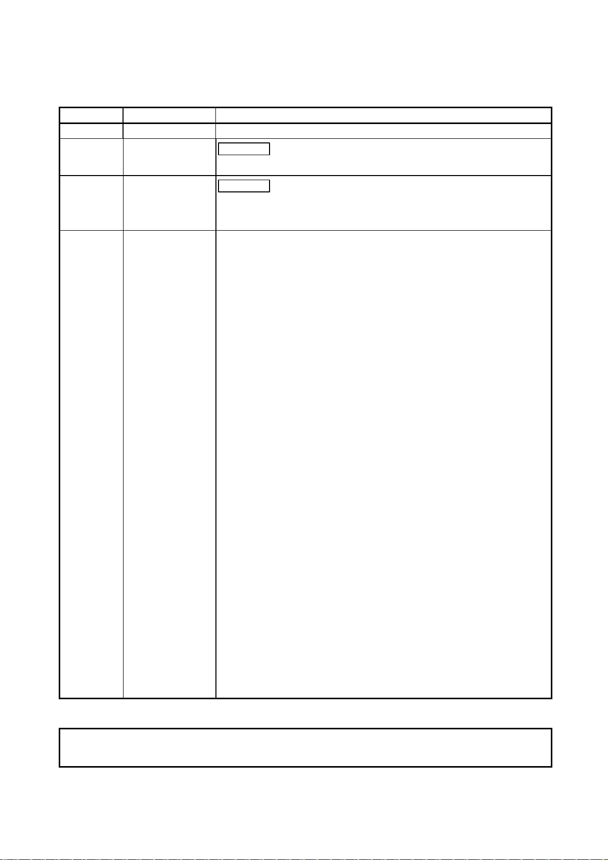
[Start-Up/Maintenance Instructions]
!
CAUTION
• Before performing the OPR, JOG operation, inching operation, posit ioning data test or other
operation in the test mode, read the manual carefully, fully ensure safety , and set the PLC CPU
to STOP.
Not doing so can damage the machine or cause an accident due to misoperation.
A - 1
Page 3
REVISIONS
* The manual number is given on the bottom left of the back cov er.
Print Date * Manual Number Revision
Feb., 2000 SH (NA)-080057-A First edition
May., 2000 SH (NA)-08005 7 -B
Correction
Section 4.1, 7.4, Chapter 9, Section 11.1.4, Section 11.5
Oct., 2000 SH (NA)-080057-C
Correction
CONTENTS, Chapter 1, Section 2.1, Chapter 6, Section 6.1, Section 7.1,
Section 8.2.1, Chapter 9, Section 10.4, APPENDIX, INDEX
Japanese Manual Version SH-080048-D
This manual confers no industrial property rights or any rights of any other kind, nor doe s it confer any patent licenses.
Mitsubishi Electric Corporation cannot be held responsible for any problems inv olv ing industria l property rights which
may occur as a result of using the contents noted in this manual.
2000 MITSUBISHI ELECTRIC CORPORATION
A - 2
Page 4

Recommendation of Software Registration
After you have acknowledged the contents of the "Software Usage Agreement"
supplied with the product, fill out the "Software Registration Card" and return it to us to
obtain the following services.
We will send you the user ID and "Registration Confirmation Card" after making the
user registration of the "Software Registration Card" you returned.
(No extra charg e i s need ed fo r r egi st rat io n. )
(1) Software registration
By returning the "Software Registration Card" supplied with the product, we offer
you the new product news, update information and other latest information by direct
mail.
(2) Instructions for inquiries
When making inquires, please give us specific and clear information in the terms
used in the manual.
Please give us detailed information on the phenomenon that may have caused the
problem as we need the information to reproduce that phenomenon.
Please contact the corresponding makers for the operating system of the personal
computer and the commercially available software of other companies.
A - 3
Page 5

INTRODUCTION
Thank you for choosing the Mitsubishi MELSEC-Q Series General-Purpose Programmable Logic Controller.
Before using the product, please read this manual carefully to use the equipment to its optimum.
SAFETY INSTRUCTIONS.............................................................................................................................A- 1
REVISION ......................................................................................................................................................A- 2
Recommendation of Software Registration...................................................................................................A- 3
CONTENTS....................................................................................................................................................A- 4
About Manuals ...............................................................................................................................................A- 7
How to Use This Manual................................................................................................................................A- 8
About the Generic Terms and Abbreviations ................................................................................................A-10
Packing List ....................................................................................................................................................A-10
CONTENTS
1. OVERVIEW 1- 1 to 1- 8
1.1 Features ...................................................................................................................................................1- 2
1.2 Manual Makeup........................................................................................................................................1- 6
1.3 Additions/Modifications Function according to SW0D5C-QD75P-E Versions.......................................1- 8
2. SYSTEM CONFIGURATION 2- 1 to 2- 6
2.1 System Configuration...............................................................................................................................2- 1
2.2 Operating Environment............................................................................................................................2- 5
3. FUNCTION LIST 3- 1 to 3- 4
3.1 Function List .............................................................................................................. ...............................3- 1
3.2 Menu list ...................................................................................................................................................3- 3
4. INSTALLATION AND UNINSTALLATION 4- 1 to 4-12
4.1 Installation ................................................................................................................................................4- 1
4.2 Uninstallation............................................................................................................................................4- 6
4.3 Starting SW
4.4 Exiting SW
5. SCREEN MAKEUP AND BASIC OPERATIONS 5- 1 to 5- 4
5.1 Screen Makeup and Display Selection ...................................................................................................5- 1
5.2 Basic Operations......................................................................................................................................5- 2
D5C-QD75P-E ..................................................................................................................4-10
D5C-QD75P-E....................................................................................................................4-11
6. PROJECT CREATION 6- 1 to 6-14
6.1 Creating a New Project............................................................................................................................6- 2
6.2 Opening the Existing Project ...................................................................................................................6- 5
A - 4
Page 6

6.3 Saving the Project....................................................................................................................................6- 6
6.4 Closing the Project...................................................................................................................................6- 7
6.5 Deleting the Project..................................................................................................................................6- 8
6.6 Reading Other Format Files ....................................................................................................................6- 9
6.6.1 Reading SW1IVD-AD75P-E format file ............................................................................................6- 9
6.6.2 Reading the CSV format file .............................................................................................................6-11
6.7 Write to CSV Format File.........................................................................................................................6-13
7. SYSTEM CHECKING FROM PERIPHERAL DEVICE 7- 1 to 7- 8
7.1 Connection Setup.....................................................................................................................................7- 1
7.2 System Monitor ........................................................................................................................................7- 4
7.3 Checking the QD75 Function Version (OS Information) ........................................................................7- 5
7.4 Checking Connect....................................................................................................................................7- 6
8. DATA SETTING 8- 1 to 8-16
8.1 Parameter Setting....................................................................................................................................8- 1
8.2 Positioning Data Setting...........................................................................................................................8- 3
8.2.1 Positioning data................................................................................................................................. 8- 3
8.2.2 M code comment...............................................................................................................................8- 8
8.3 Simulation.................................................................................................................................................8- 9
8.4 Block Start Data Setting...........................................................................................................................8-12
8.4.1 Block start data..................................................................................................................................8-12
8.4.2 Condition data ...................................................................................................................................8-14
8.5 Error Check ..............................................................................................................................................8-16
9. QD75 DATA WRITE / R EA D /VE R IFY 9- 1 to 9- 4
9.1 Write to QD75/Read from QD75/Verify QD75 Data ...............................................................................9- 1
9.2 Flash ROM write request.........................................................................................................................9- 4
9.3 QD75 Initialization....................................................................................................................................9- 4
10. POSITIONING DEBUGGING 10- 1 to 10-32
10.1 QD75 Error Check ...............................................................................................................................10- 2
10.2 Monitor..................................................................................................................................................10- 3
10.2.1 Monitoring the positioning data/block start data...........................................................................10- 3
10.2.2 Operation monitor..........................................................................................................................10- 4
10.2.3 History monitor ..............................................................................................................................10- 6
10.2.4 Signal monitor................................................................................................................................10- 8
10.2.5 Axis operation monitor ..................................................................................................................10-11
10.3 Sampling Monitor.................................................................................................................................10-17
10.3.1 Sampling signal monitor................................................................................................................10-17
10.3.2 Sampling buffer monitor................................................................................................................10-19
10.4 Test.......................................................................................................................................................10-21
10.4.1 Positioning start test......................................................................................................................10-22
10.4.2 Present value change test ............................................................................................................10-25
A - 5
Page 7

10.4.3 Speed change test ........................................................................................................................10-26
10.4.4 OPR test ........................................................................................................................................10-28
10.4.5 JOG/MPG operation test...............................................................................................................10-30
11. USEFUL FUNCTIONS 11- 1 to 11-38
11.1 Useful Functions for Projects...............................................................................................................11- 1
11.1.1 Verifying the project data ..............................................................................................................11- 1
11.1.2 Changing the QD75 model after data setting...............................................................................11- 3
11.1.3 Intelligent function utility................................................................................................................11- 4
11.1.4 Multi-module batch write...............................................................................................................11- 6
11.2 Edit Functions for Data Setting............................................................................................................11- 8
11.2.1 Cut/copy/paste ..............................................................................................................................11- 8
11.2.2 Jump..............................................................................................................................................11-12
11.2.3 Clearing the rows/columns ...........................................................................................................11-13
11.2.4 Initializing the data.........................................................................................................................11-14
11.3 Copying the Data .................................................................................................................................11-15
11.3.1 Copying the data on an axis basis (Axis copy)............................................................................11-15
11.3.2 Block start copy.............................................................................................................................11-16
11.4 Navigation Function.............................................................................................................................11-17
11.5 Option Setting.......................................................................................................................................11-20
11.6 Printing the Project Data......................................................................................................................11-22
11.6.1 Printer setting ................................................................................................................................11-22
11.6.2 Printing...........................................................................................................................................11-23
11.7 Positioning Data Setting in Test Mode................................................................................................11-26
11.7.1 Teaching........................................................................................................................................11-26
11.7.2 Positioning data test edit...............................................................................................................11-28
11.8 Wave Trace..........................................................................................................................................11-29
11.8.1 Wave trace condition setting.........................................................................................................11-29
11.8.2 Wave trace execution....................................................................................................................11-31
11.9 Locus Trace..........................................................................................................................................11-33
11.9.1 Locus trace condition setting ........................................................................................................11-33
11.9.2 Locus trace execution...................................................................................................................11-35
11.10 Help ....................................................................................................................................................11-37
APPENDIX Appendix - 1 to Appendix - 2
APPENDIX 1 QD75 READ/WRITE REFERENCE PROCESSING TIMES....................................Appendix - 1
INDEX Index - 1 to Index - 5
A - 6
Page 8
About Manuals
Related Manu al s
The following manuals are related to this product.
Refer to the fo llowing table and r eq ue st th e req uired ones.
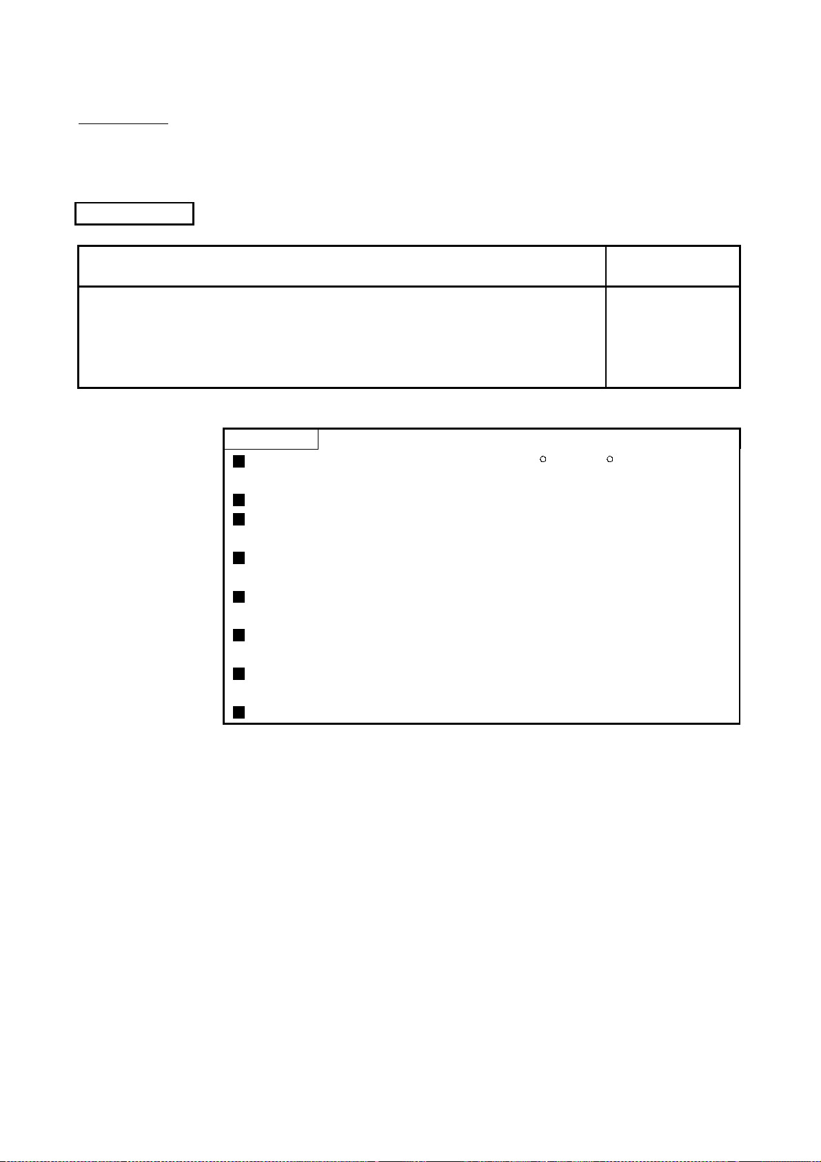
Manual Name
Type QD75P1/QD75P2/QD75P4, QD75D1/QD75D2/QD75D4 Positioning Module User's
Manual
Describes the system configuration, performance specifications, functions, handling, pre-operation
procedures and troubleshooting of the QD75P1/QD75P2/QD75P4 and QD75D1/QD75D2/QD75D4.
(Option)
CAUTION
Please note that we do not guara ntee the MicrosoftR WindowsR Operating System
corresponding commercially available software products th at we int roduce.
The software copyright of this product belongs to Mitsubishi Electric Corporation.
No part of the contents of this manual may be reproduced or transmitted in any
form or by any means without the permission of our company.
Some part of the contents of this manual may not follow the revisions of the
software and hardware.
In principle, the software of this product should be purchased per computer as a
set or under license.
This product (including the manual) may only be used under the software using
agreement.
Please note that we are not responsible for any influence resulting from the
operation of this product (including the manual).
The contents of this manual are subject to change without notice.
Manual Number
(Model Code)
SH-080058
(13JR09)
A - 7
Page 9
How to Use This Manual
PURPOSE
Purpose of operation explained in each
chapter, section or paragraph.
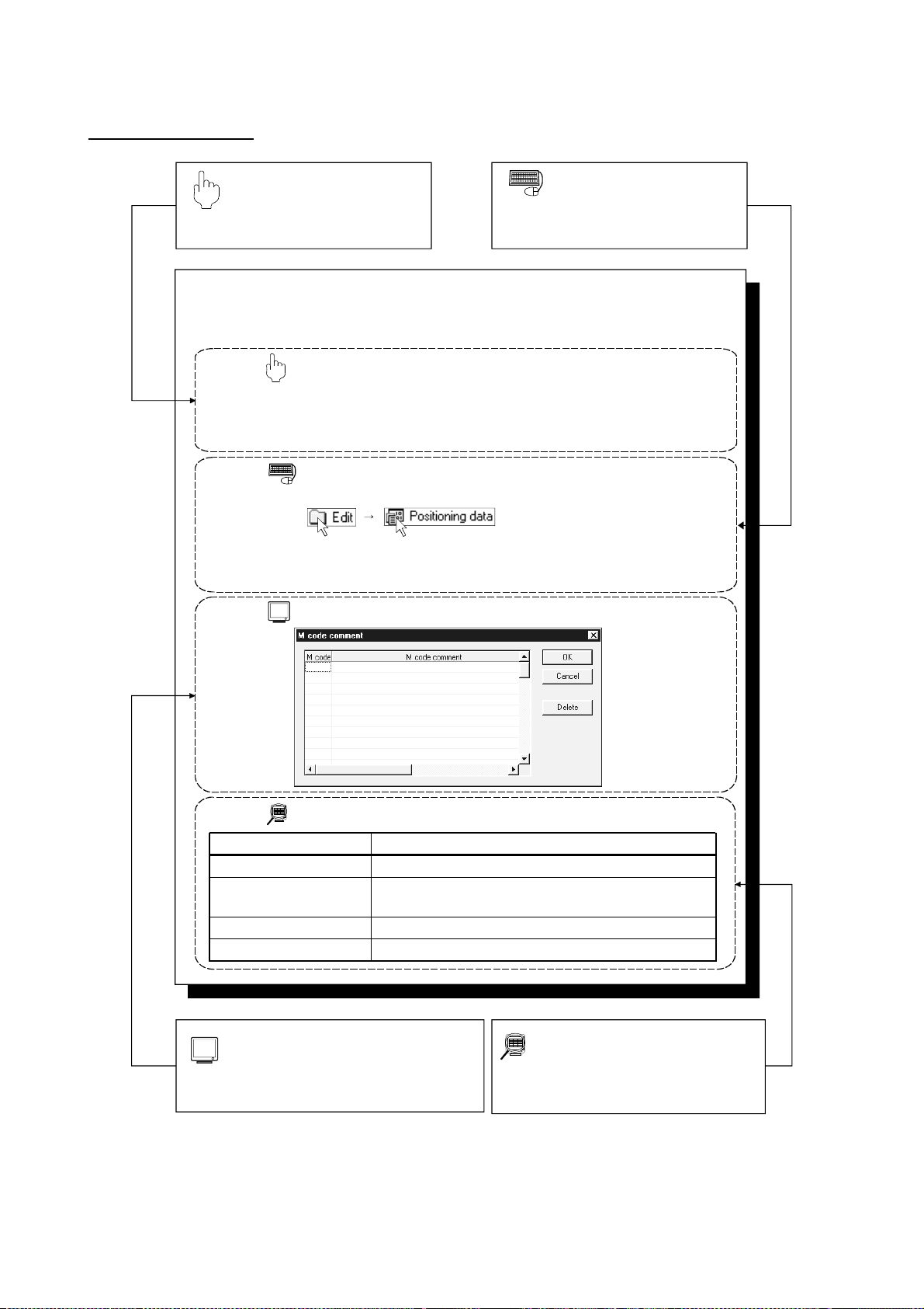
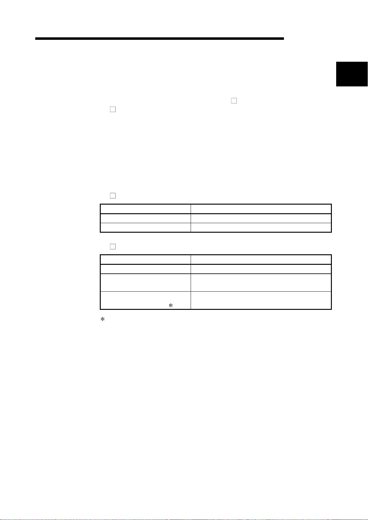
8.2.2 M code comment
PURPOSE
Set comments to M codes which are required for control exercised in
synchronization with positioning.
M code comments are data which can be saved only on the peripheral device.
Up to 50 comments can be set for each axis.
BASIC OPERATION
1. Choose the positioning data of the axis to which the M code comments will be set.
2. Click the [Edit] → [M code comment] menu.
3. Set the M code comments.
4. To exit, click the "OK" button in the M code comment dialog box.
DISPLAY/SETTING SCREEN
BASIC OPERATION
Operation to be performed until the actual
operation screen appears.
Double-click.Double-click.
DISPLAY/SETTING DATA
Item
M code
M code comment
"OK" button
"Delete" button
Set the M code No. to be commented.
Set a comment of up to 32 characters.
Up to 50 comments can be set for each axis.
Click this button to finish the setting.
Click this button to delete the comment chosen.
DISPLAY/SETTING SCREEN
Screen used to make setting or provide display
for the purpose being described.
A - 8
Description
DISPLAY/SETTING DATA
Explains the display/setting screen items.
Page 10
In addition, there are also the following explanations.
HELPFUL OPERATION
Describes application operation if there are multiple purposes and the basic operation and display/setting data
do not provide enough information.
HELPFUL CORRECTIVE ACTIONS
Explains basic corrective actions if monitored data is abnormal or a test cannot be made.
Provides information relevant to that page, e.g. the items you should be careful of and the functions you should
know.
The following table lists the symbols used in this manual and their definitions.
Symbol Description
Represents the menu name of the menu bar.
If the menu name differs among Axes #1 to #4, they are indicated #1 to #4.
[ ]
( )
" "
<< >>
[ ]
Example: [Project]
[Online]
Represents the tool button on the toolbar corresponding to the drop-dow n menu.
If the button differs among Axes #1 to #4, the buttons of #1 to #4 are indicated.
Example: [Project] [Save Project] menu ( )
[Online] [Test] [M code Off] [M code #1 to #4 Off] menu ( to )
Represents the item name or command button in the dialog box.
Example: "OK" button
Represents the tab in the dialog box.
Example: <<Basic Parameter 1>> tab
[ ] indicates a drop-down menu.
[New Project] menu
[Test] [Operation test #1 to #4] menu
A - 9
Page 11
About the Generic Terms and Abbreviations
The following generic terms and abbreviations for the positioning software packages,
positioning modules, etc. are used in this manual.
Generic Term/Abbreviation Description
SW D5C-QD75P-E
SW D5C-AD75P-E
SW1IVD-AD75P-E
Peripheral device Generic term for personal computers on which SW D5C-QD75P-E may be used.
QD75
AD75
QD75 User's Manual
Servo amplifier Generic term for pulse input-compatible drive units that may be con nected to t he Q D75
Servo motor Generic term for motors connected to the drive units (servo amplifiers)
Positioning system
Abbreviation for type SW0D5C-QD75P-E positioning module software package for
MELSEC-Q series
Abbreviation for type SW0D5C-AD75P-E AD75 positioning module software package
for MELSEC-A series
Generic term for type SW1IVD-AD75P-E positioning module software packages for
MELSEC-A series
Generic term for type QD75P1, QD75P2, QD75P4, QD75D1, QD75D2 and QD75D 4
positioning modules
Generic term for MELSEC-A series positioning modules that may be used w ith
SW
D5C-AD75P-E
Abbreviation for the following relevant manual
• Type QD75P1/QD75P2/QD75P4, QD75D1/QD75D2/Q D75D 4 Positioning M odule
User's Manual
Generic term for equipment sets which exercise positioning control, including the
positioning modules, servo amplifiers, servo motor s and external switches
Packing List
License key FD SW0D5F-QD75PKEY-E: 1 pc.
This product consists of the following.
CD-ROM SW0D5C-QD75P-E: 1 pc.
A - 10
Page 12
1. OVERVIEW
1. OVERVIEW
MELSEC-Q
This manual describes the functions and operating procedures of positioning module
software package (hereinafter referred to as "SW
SW
D5C-QD75P-E is a positioning module software package which can perform the
following functions via the QCPU, Q corresponding serial communication module or Q
corresponding MELSECNET/H network remote I/O module.
• Setting of positioning data and parameters
• Simulation using positioning data
• Read/write of data from/to positioning module
• Monitoring of positioning control status
• Test operation of positioning control
• Automatic refresh setting between QCPU devices and QD75 buffer memory
SW
D5C-QD75P-E can be used with any of the following positioning modules.
Positioning Type Type
Open collector output type QD75P1,QD75P2, QD75P4
Differential driver output type QD75D1,QD75D2, QD75D4
D5C-QD75P-E").
1
SW D5C-QD75P-E can access the QD75 via any of the following modules.
Module Type Type
QCPU Q02CPU, Q02HCPU, Q06HCPU, Q12HCPU, Q25HCPU
Q corresponding serial
communication module
Q corresponding MELSECNET/H
network remote I/O module
Only when connecting to the remote I/O module directry.
QJ71C24, QJ71C24-R2
QJ72LP25-25, QJ72BR15
1 - 1
Page 13
1. OVERVIEW
1.1 Features
MELSEC-Q
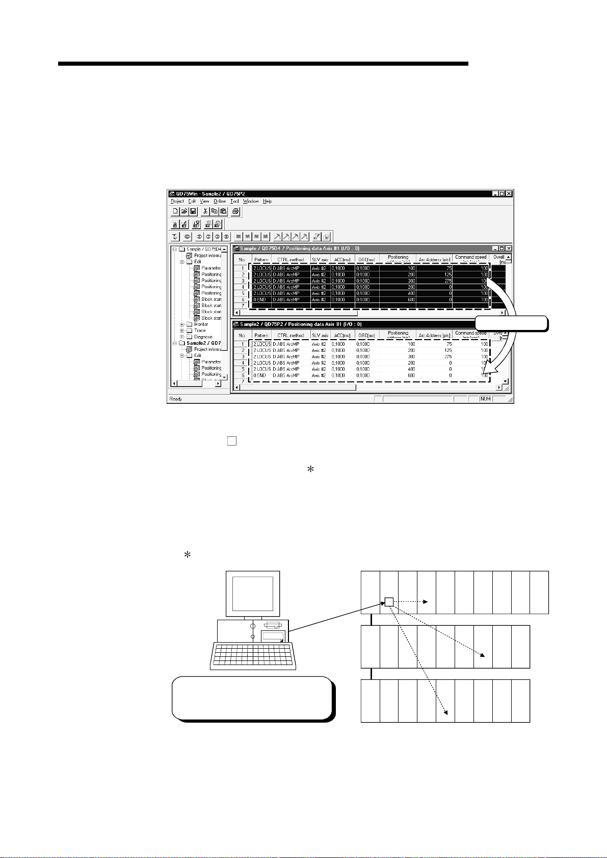
(1) Concurrent editing of multiple projects
Capable of opening multiple projects simultaneously, this software allows you to
easily edit the positioning data and block start data to be utilized by copying and
pasting.
Copy & paste
(2) Efficient de bug gi ng of mul t i - modules
Since SW
D5C-QD75P-E access to the QD75 is made via the QCPU, Q
corresponding serial communication module or Q corresponding MELSECNET/H
network remote I/O module
, a direct connection cable to the QD75 on the main/
extension base unit is not needed.
Also, because the QD75 to be connected to is set per project, batch write to or
monitoring of multi-modules can be performed.
When using multiple QD75s, you can reduce the software start waiting time and
physical work time, increasing debugging efficiency.
Only when connecting to the remote I/O module directry.
QCPU QD75
QD75
Batch write to or monitoring of multiple
QD75s can be performed from connection
cable to QCPU.
QD75
1 - 2
Page 14
1. OVERVIEW
MELSEC-Q
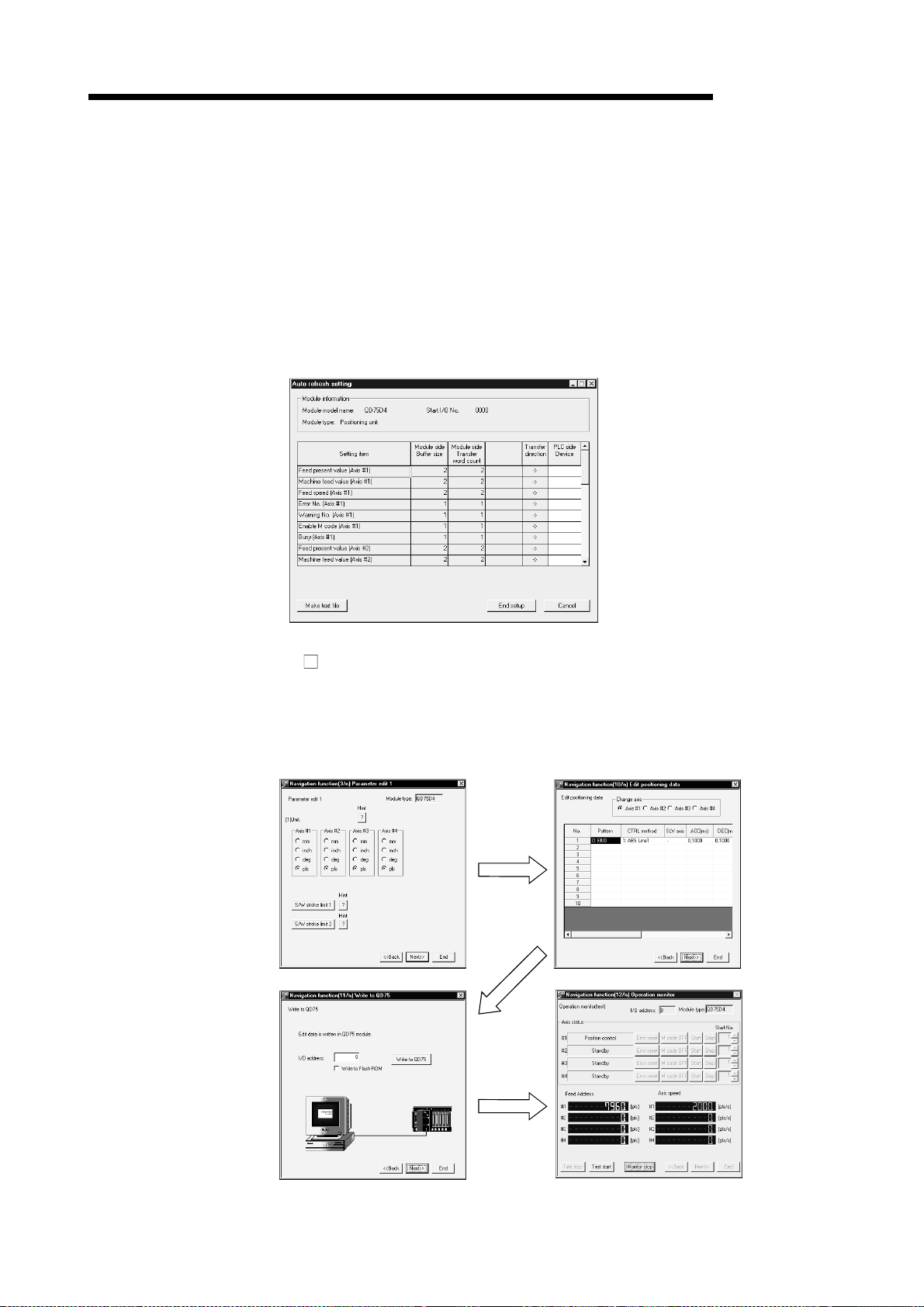
(3) Simplified sequence program by automatic refresh setting
Automatic refresh setting is made to automatically read the following values stored
in QD75 buffer me mory to t he QCP U devi ce s.
• Feed present value
• Machine feed value
• Feed speed
• Error No.
• Warning No.
• Enable M code
Automatic refresh setting reduces the number of FROM instructions used to read
the buffer memory storage values, facilitating creation and debugging of sequence
programs.
(4) Ease of operation with navigation function
SW
D5C-QD75P-E has a navigation function which can perform operations from
data setting, write to the QD75, monitoring, test to data storage in a sequential
order.
As basic settings and debugging can be performed in orderly sequence, you can
understand operations necessary for this software package and positioning
control.
Parameter setting
Write to QD75
Positioning data setting
Debugging by test operation
1 - 3
Page 15
1. OVERVIEW
MELSEC-Q
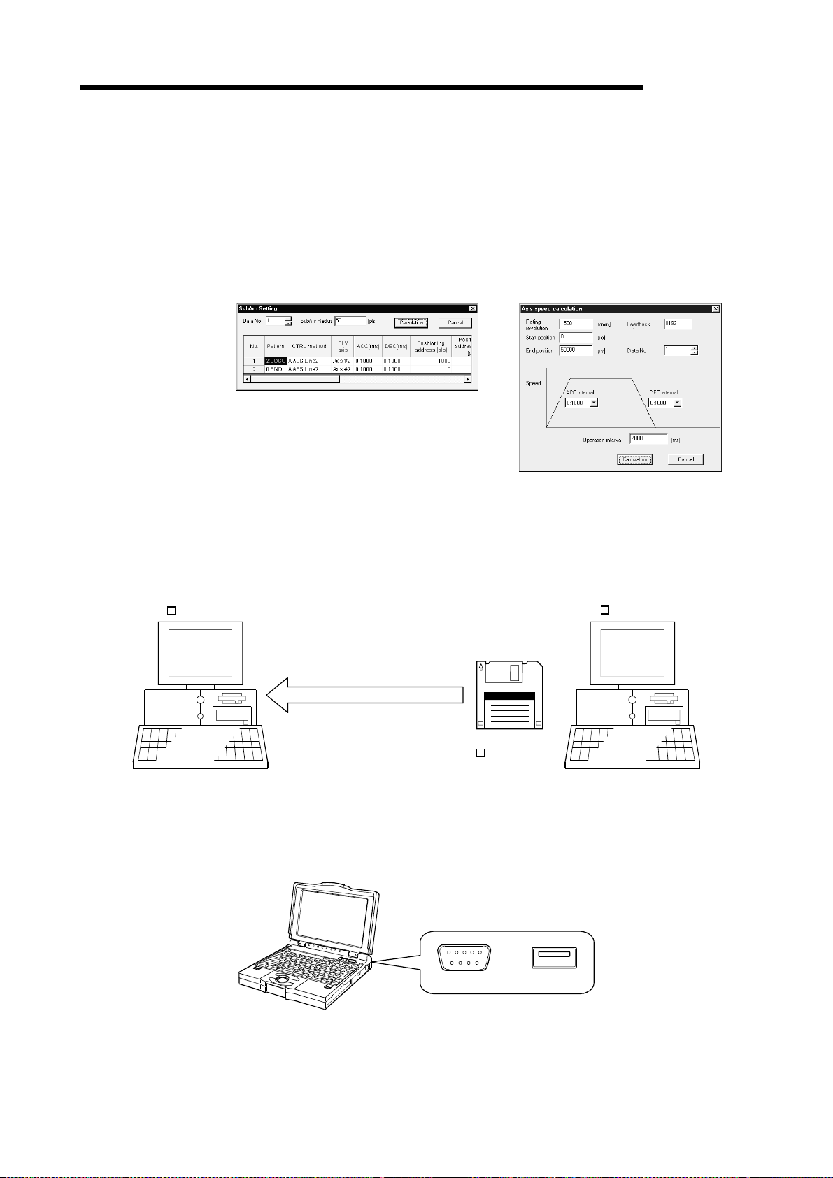
(5) Setting of op ti mu m po sit i onin g data wi t hou t compl i cat ed cal cula ti on
Positioning data can be set by sub arc setting and automatic axis speed setting.
Sub arc setting generates from the specified two linear interpolation control data
the circular i nte r pol a tio n con trol da ta in wh i ch th e an gl e b e tw e en two lin ea r pa ths
is converted into a circular arc (curve) path.
Sub axis speed setting calculates the axis speed (command speed) from the
operation time, travel, acceleration/deceleration time and motor specifications.
[Sub arc] [Speed of axis setting]
(6) Ease of migration from AD75
SW D5C-QD75P-E
(7) Versatility by compatibility with RS-232 and USB
These functions allow the optimum positioning data to be set without complicated
calculation and advance measurement.
You can read and use the data created on A series SW1IVD-AD75P-E and
SW0D5C-AD75P-E.
Valuable data is not wasted and can be utilized for QD75.
SW D5C-AD75P-E
Open another format file.
Existing data created
on SW D5C-AD75P-E
If the personal computer does not have a free serial port, connection can be
made from the USB connector.
Especially for a notebook computer having a few serial ports, there are no
restrictions due to shortage of ports.
1 - 4
and
RS-232 USB
Page 16
1. OVERVIEW
MELSEC-Q
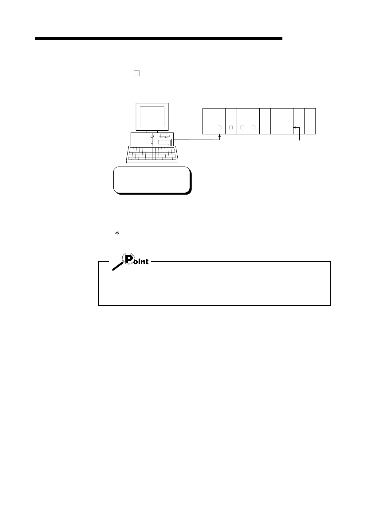
(8) Compatible with multiple PLC syst e m
On SW
PLC No. of the QD75 to communicate with in Connection Setup (refer to Section
7.1) allows communication to be made with any QD75.
In Connection Setup, specify the
control PLC type and PLC No. of
the QD75 to communicate with.
(Example)
Connection Setup for communication with the QD75 under control of PLC No. 1
PLC type: Type of P LC No . 1 , Mul tiple PLC settin g: PLC N o . 1
D5C-QD75P-E (Version 30D or later), setting the control PLC type and
PLC
PLC
PLC
No. 1
No. 2
No. 3
PLC
No. 4
QD75QCPU QCPUQCPU QCPU QD75 QD75
123
PLC No. of
control PLC
:For details, refer to "QCPU (Q Mode) User's Manual (Function Explanation,
Program Fundamentals)".
• Communication with the QD75 cannot be made if the control PLC type and PLC
No. of the QD75 to communicate with are not set correctly in Connection Setup.
• If correct settings have been made in Connection Setup, any of PLC No. 1 to No. 4
may be specified as the connection target of the connection cable.
1 - 5
Page 17
1. OVERVIEW
MELSEC-Q
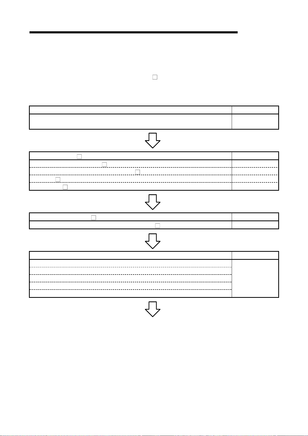
1.2 Manual Ma keup
This manual is made up of 11 chapters and appendices.
This manual assumes that SW
positioning system checking to operation in the following procedure.
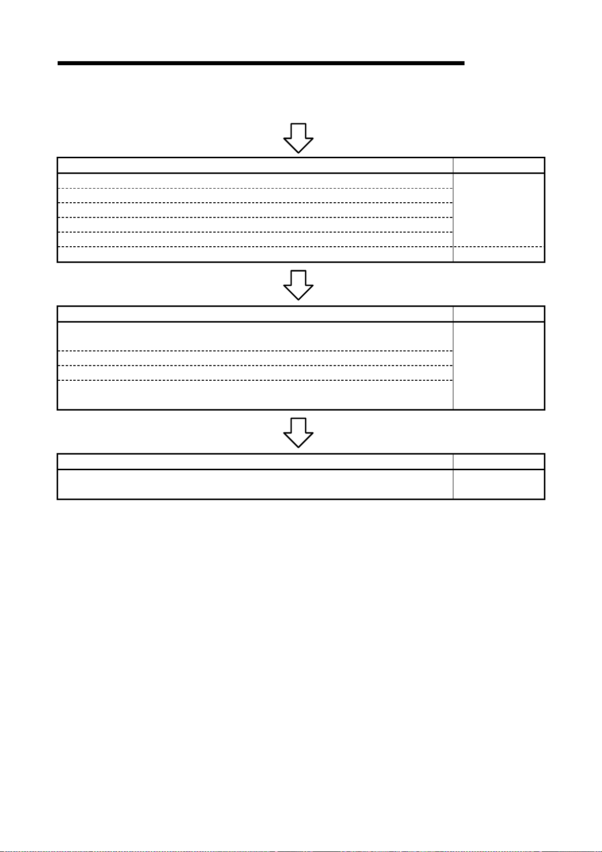
<Sequence of steps taken by the user up to positioning system operation>
Step 1: Install and wire the positioning system. Refer To
• Install and wire the PLC (such as the QCPU, QD75, I/O modules and intelligent fu nction
modules), servo amplifiers, motors, external sw itches and other external devices.
Step 2: Check the SW D5C-QD75P-E functions and learn the basic operations. Refer To
• Check the system with which SW D5C-QD75P-E can be used. Chapter 2
• Check the functions that can be performed by S W D5C-QD 75P-E. Chapter 3
• Install SW D5C-QD75P-E in the peripheral device and start the program. Chapter 4
• Learn the SW D5C-QD75P-E screen makeup and basic operations. Chapter 5
D5C-QD75P-E is used to perform steps from
QD75 User's
Manual
Step 3: Start operation of SW D5C-QD75P-E. Refer To
• Create a project which will be the object of operation for S W D5C-QD75P-E. Chapter 6
Step 4: Check the connection and initial operation of the positioning sy stem. Refer To
• Specify the QD75 to be accessed, ports where cables w ill be connected, and others.
• Check the QD75 types and I/O addresses of the stations connected.
• Check connection according to the signal states fro m the external devices.
• Check the alarms and warnings of the positioning module.
• Check that the servo motors are run by JOG operation.
Chapter 7
(To the next page)
1 - 6
Page 18
1. OVERVIEW
MELSEC-Q
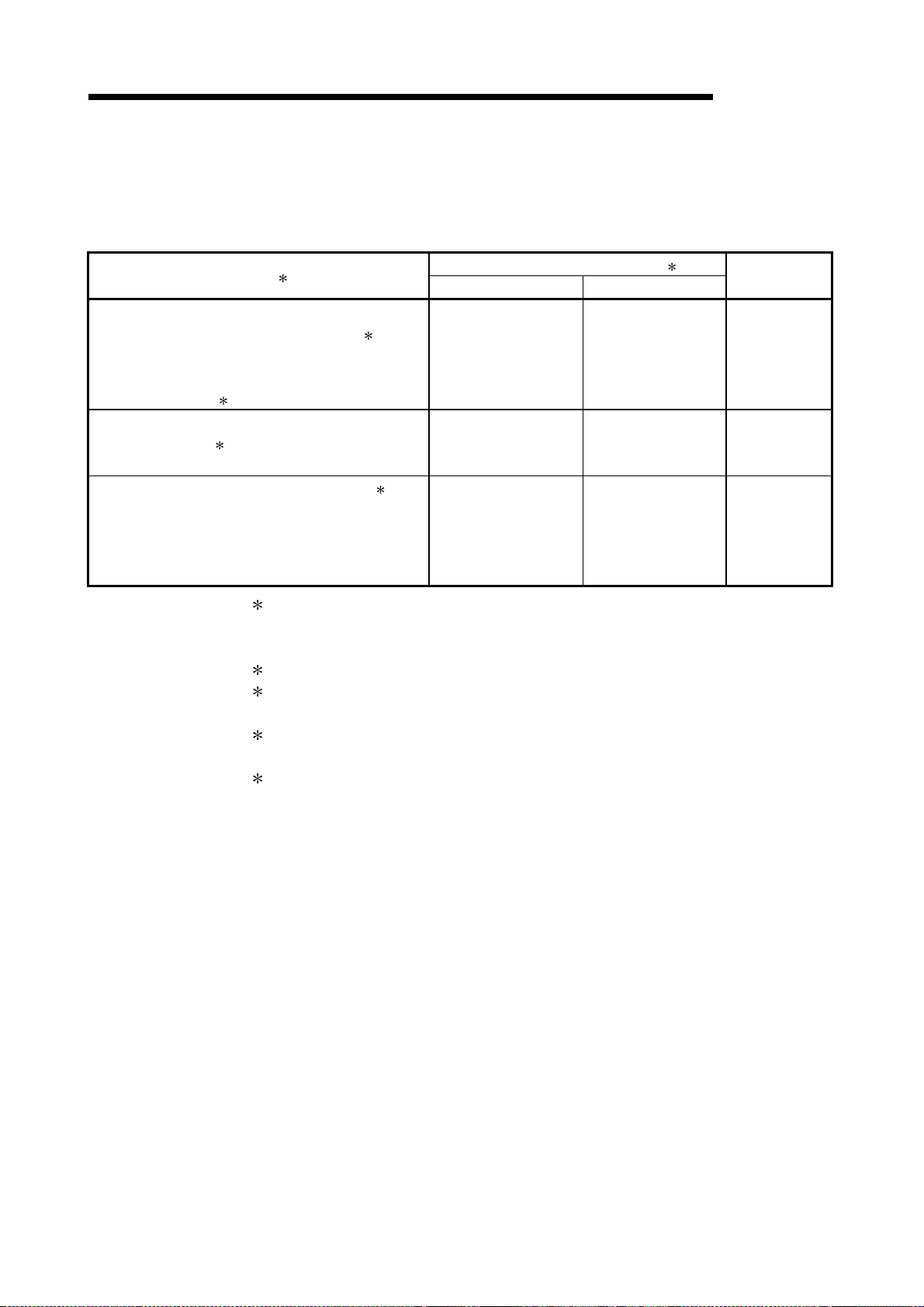
(From the pre cedi ng pa ge )
Step 5: Set and write data to the positioning module. Refer To
• Set the parameters appropriate for the positioning system and control.
• Set the positioning data and M code comments.
• Check the positioning data on the simulation screen.
• Make the corresponding setting if block start data and/or conditio n data is req uired.
• Make error check to check the parameters, positioning data and b lock start data settings.
• Write, read or verity the set data on the project. Chapter 9
Step 6: Perform test operation and check and adjust the settings. Refer To
• Make online error check to recheck the settings of the parameters, p ositio ning data a nd bloc k
start data written to the QD75.
• Check positioning control and test on the monitor screen.
• Set the positioning data and block start data, and perform test operation.
• Make present value change test, speed change test, OP R test, JO G operation test and MPG
operation test to check the parameters, addresses, axis speeds, etc.
Chapter 8
Chapter 10
Step 7: Positioning system operation Refer To
• Operate the positioning system with the PLC CPU program.
QD75 User's
Manual
1 - 7
Page 19
1. OVERVIEW
1.3 Additions/Modifications Function according to SW0D5C-QD75P-E Versions
Additions/Modifications Functions for each Versions of SW0D5C-QD75P-E are given
below.
MELSEC-Q
Function 1
Connection Setup
• Addition of PLC No. setting of multiple PLC 3
(for multiple PLC system)
• Addition of Q corresponding MELSECNET/H network
remote I/O module
Addition of parameter for speed-position switching
control (ABS mode) 5
<Speed-position function selection>
Signal monitoring for pre-reading start function 5
<Y14: Axis #1 execution prohibition flag>
<Y15: Axis #2 execution prohibition flag >
<Y16: Axis #3 execution prohibition flag >
<Y17: Axis #4 execution prohibition flag >
4 connection setup
1:Compatible with the function version "B" of the QD75. For confirmation of the QD75
function version, refer to "Section 7.3 Checking the QD75 Function Version (OS
Information)".
2:For confirmation of the SW0D5C-QD75P-E version, refer to "Section 11.10 Help".
3:For detail s, refe r to "QCP U ( Q Mo de ) Use r' s Man ua l ( Fun cti on Ex pl an at io n,
Program Fundamentals)".
4:For deta il s , re fe r to "Q Correspondi ng MELSE C NE T/ H Ne tw o r k Sy ste m Reference
Manual (Remote I/O Net)".
5:For details, refer to "QD75 User's Manual" (SH-080058-B or later).
Versions of SW0D5C-QD75P-E 2
Version 30D or later Version 20C or below
Yes No Section 7.1
Yes No Section 8.1
Yes No Section 10.2.4
Reference
1 - 8
Page 20
2. SYSTEM CONFIGURATION
2. SYSTEM CONFIGURATION
2.1 System Configuration
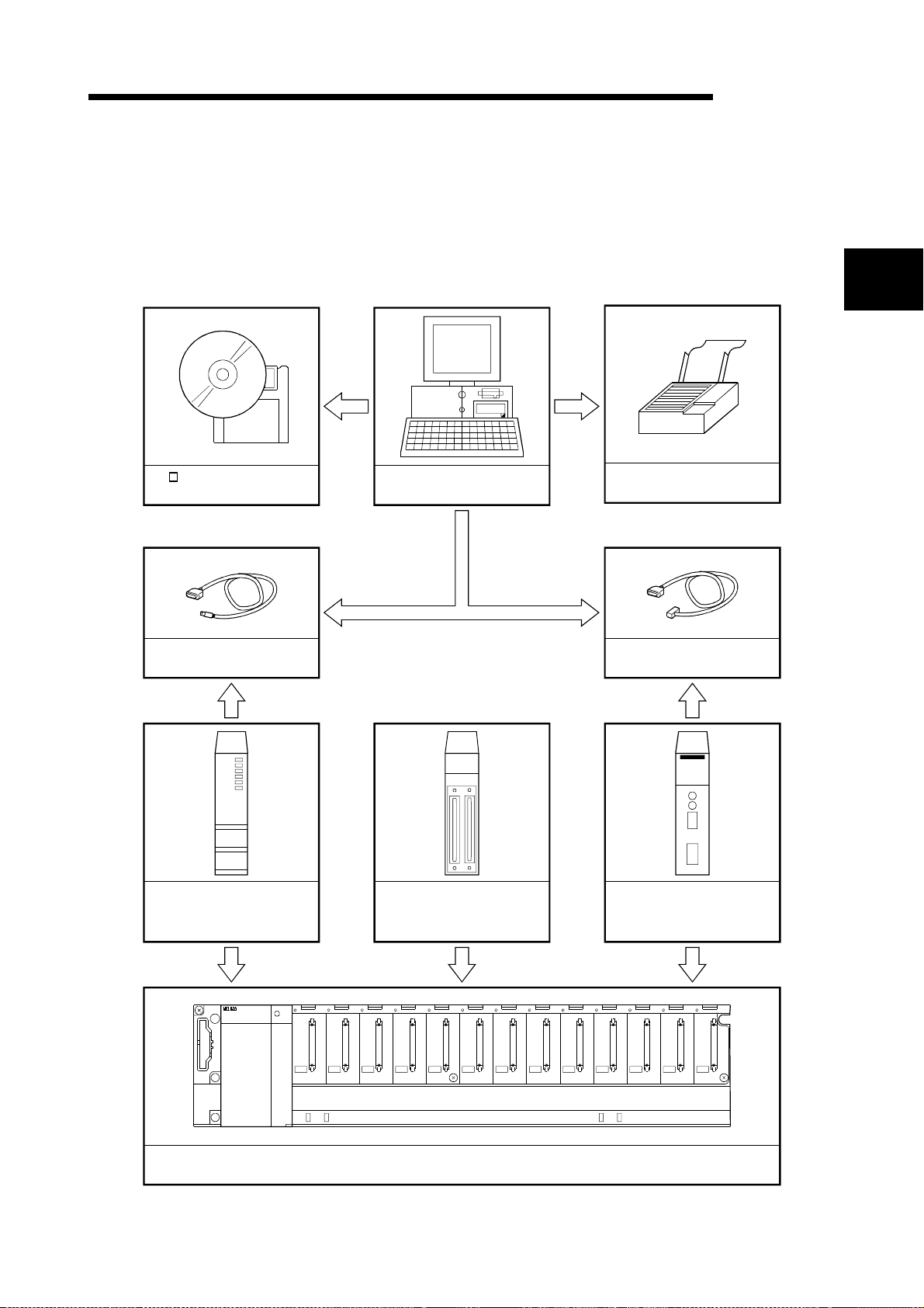
(1) Overall configuration of this system
MELSEC-Q
(a) Via QCPU, Q corresponding serial communication module
SW D5C-QD75P-E(CD-ROM)
License key FD
QC30R2 or USB cable
(user-prepared)
Peripheral device
2
Printer
RS-232 cable
(user-prepared)
QCPU (Q mode)
(Q02CPU,Q02HCPU,Q06HCPU
Q12HCPU,Q25HCPU)
POWER
F6
QD75P1/P2/P4
QD75D1/D2/D4
Main or extension base unit
and power supply module
2 - 1
Q corresponding serial
communication module
(QJ71C24,QJ71C24-R2)
Page 21
2. SYSTEM CONFIGURATION
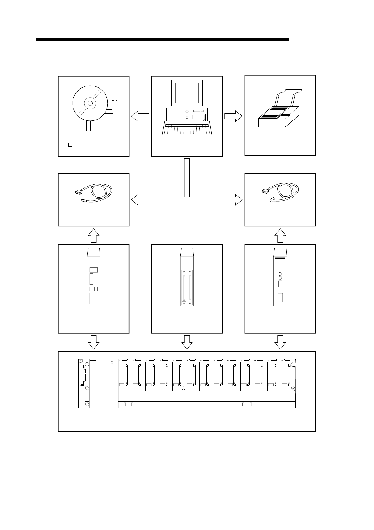
(b) Connecting to Q corresponding MELSECNET/H network remote I/O module directry
MELSEC-Q
SW D5C-QD75P-E(CD-ROM)
License key FD
QC30R2 cable
(user-prepared)
Q corresponding MELSECNET/H
Network remote I/O module
(QJ72LP25-25, QJ72BR15)
Peripheral device
QD75P1/P2/P4
QD75D1/D2/D4
Printer
RS-232 cable
(user-prepared)
Q corresponding serial
communication module
(QJ71C24,QJ71C24-R2)
POWER
F6
Main or extension base unit
and power supply module
2 - 2
Page 22
2. SYSTEM CONFIGURATION
• Do not connect a peripheral device to the Q corresponding serial communication
module by multidrop link.
• Concurrent use of this product on multiple personal computers is illegal.
Therefore, this product may only be used on the personal computer specified in
the software re gi st rati on ca rd.
However, to prepare for any unexpected situation, e.g. hard disk crash of the
personal computer, the license key FD is designed to be installable up to five
times.
When you use the FD on another personal computer, you regain one installation
right by uninstalling the license key FD. (i.c. number of allowable installations
increases by one.)
• By installing the license key FD, the product can be started. (Refer to Section 4.1.)
• Ensure the computer that the FD license key has been installed on is easily
identifiable, and store the FD safely.
If you mislay the license key FD or the license key FD does not match the
personal computer where it has been installed, it cannot be installed or
uninstalled.
MELSEC-Q
(2) About the connection cables
(a) Connecti on to QCP U or Q cor re spo ndi ng MELS EC N E T/H ne tw o rk re mot e I / O
module by QC30R2 (made by Mitsubishi Electric)
When the baudrate is set to 115.2/57.6kbps, communication cannot be made
unless the peripheral device used is compatible with the communication speed
of 115.2/57.6kbps.
If a communication error occurs, reduce the baudrate setting and restart
communication.
(b) Connection to QCPU by USB cable
• Usable when Microsoft
R
WindowsR 98 Ope ra ti ng Syste m or USB driver has
been installed.
• Unusable for Micro soft
R
WindowsR 95 Operating System or Microsoft
WindowsNTR Workstation 4.0 Operating System.
• Use of the USB cable allows only PLC CPU to be connected.
R
2 - 3
Page 23
2. SYSTEM CONFIGURATION
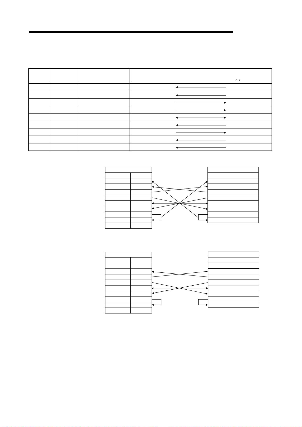
(c) Connection to Q corresponding serial communication module
The specifications of the RS-232 cable connector are indicated below.
MELSEC-Q
Pin
Number
Signal Code Signal Name
1 CD Receive carrier detection
2 RD(RXD) Receive data
3 SD(TXD) Send data
4 DTR(ER) Data terminal ready
5 SG Send ground
6 DSR(DR) Data set ready
7 RS(RTS) Request to send
8 CS(CTS) Clear to send
9 RI(CI) Call indication
• Connection example which can turn ON/OFF CD signal (No. 1 pin)
QJ71C24(-R2) Side
Signal code
RD(RXD)
SD(TXD)
DTR(ER)
DSR(DR)
RS(RTS)
CS(CTS)
CD
SG
RI(CI)
Signal Direction
Q corresponding serial communication module
Other End Device Side
Pin number
1
2
3
4
5
6
7
8
9
Signal code
CD
RD(RXD)
SD(TXD)
DTR(ER)
SG
DSR(DR)
RS(RTS)
CS(CTS)
external device
• Connection ex a mpl e wh i ch ca nno t t u rn ON/ O FF CD si gn al (No . 1 pi n )
Connection example for exercising DC code control or DTR/DSR control
QJ71C24(-R2) Side
Signal code
CD
RD(RXD)
SD(TXD)
DTR(ER)
SG
DSR(DR)
RS(RTS)
CS(CTS)
RI(CI)
Pin number
1
2
3
4
5
6
7
8
9
Other End Device Side
Signal code
CD
RD(RXD)
SD(TXD)
DTR(ER)
SG
DSR(DR)
RS(RTS)
CS(CTS)
2 - 4
Page 24

2. SYSTEM CONFIGURATION
2.2 Operating Environment
Operate the syste m in th e fo ll ow in g env i ro nmen t.
Item Description
Peripheral device
System software
Required memory 32MB or more recommended
Hard disk free space 40MB or more
Disk drive
Display Resolution of 800 600 pixels or more
MELSEC-Q
R
Personal computer with Pentium
(recommended) CPU and WindowsR 95 upwards.
Microsoft
R
WindowsR 95 Operating System (English version), Microsoft
WindowsR 98 Operating System (English version) or Microsoft
WindowsNTR Workstation 4.0 Operating System (English version)
3.5 inch (1.44MB) floppy disk drive
CD-ROM disk drive
133MHz or more
R
Disk drive required
R
• To install the license key FD requires a 3.5 inch (1.44MB) floppy disk drive.
• Instructions for use of PDF data
To ensure comfortable operation, ensure the computer has sufficient memory.
2 - 5
Page 25

2. SYSTEM CONFIGURATION
MEMO
MELSEC-Q
2 - 6
Page 26
3. FUNCTION LIST
3. FUNCTION LIST
3.1 Function Li st
Function Description
Parameter setting
Positioning data setting
M code comment setting Set s co mm ent s t o t he M co des ass ig ned to th e po si tio nin g d at a on an ax is b asi s.
Sub arc
Edit
Monitor
Test
Automatic axis speed
setting
Block start data setting
Condition data setting
Simulation
Positioning monitor
Block start monitor
Operation monitor
History monitor Monitors the error, warning, start history of all axes.
Signal monitor Monitors the X/Y devices, external signals or status signal s of all axes.
Operation monitor Monitors the control states, QD75 parameter settings or others of all axes.
Sampling
monitor
System monitor
Cableless mode Tests the QD75 alone without wiring between the servo amplifier and motor.
Positioning data test edit
Operation
test
Signal Monitors the specified signals while simultaneously sampling them.
Buffer memory Monitors the specified buffer memory data while simultaneously sampling them.
Positioning start
Present value
change
Speed change
OPR Performs an original point return test.
JOG operation Performs a JOG operation test.
Inching operation Moves the axis over the specified distance per operation.
MPG operation Performs test operation using a manual pulse generator.
(1) Function list
The main functions of SW
Sets the basic pa rameters #1, basic parameter s #2, exten ded param eters #1, extended
parameters #2, OP R basic parameter s and OPR extended parameters .
Sets the positioning data, such as pattern, control method, acce l/decel t ime and
address, on an axis basis.
Automatically generates positioning data to ensure smooth movement on the
intersection of consecutive two-axis linear interpolations by circular interpolation.
Automatically calculates the axis speed in the constant-speed part by setting the time
taken from a positioning start until the target position is reached.
Sets the starting mode, etc. of the positioning data specified for poi nts on an axis
basis.
Sets the data which is used as a special start condit ion in the block start data on a n
axis basis.
Simulates axis operation from the setting positioning data.
Wave form data is displayed for single axis control.
Locus data is displayed for two axis interpolation control.
Enters the monitor mode from the positioning data edit window and monitors the
positioning data during operation.
Enters the monitor mode from the block start data edit window and monitors the
block start data during operation.
Monitors the operating states, such as feed present values, axis feed speeds, axis
statuses and executed positioning data numbers, of all axes.
Shows the system configuration of the host and the I/O address and model (ty pe)
of the specified QD75.
Writes the setting parameters, positioning data and block start data in the test
mode.
Specifies the positioning data number and block start data poi nt number an d
performs test operation.
Performs the change test of the feed present value.
Performs a speed change test on the axis on which a positioning start test i s being
done.
MELSEC-Q
D5C-QD75P-E are listed.
3
3 - 1
Page 27

3. FUNCTION LIST
Function Description
Diagn osis Checking connect
Waveform display
Trace
Locus display
Automatic refresh setting
Extended
Navigation
MELSEC-Q
Initializes the Q D75 and d isplays signals fr om extern al devic es.
Also tests initial op eration by JOG operation.
Traces the speed command for a given time and display s the w av eform data
relative to the time axis.
Traces the position command or real value for a given time a nd disp lay s the track
data of the axes.
Assigns the QD75 buffer memory and QCPU devices for automatic refresh
between QD75 and QCPU.
Performs operations from parameter and positioning data settings to simple te st
operation and set data storage in accordance with navigation.
3 - 2
Page 28
3. FUNCTION LIST
(
)
3.2 Menu li st
MELSEC-Q
Project
The menu bar drop-down menus are listed below.
New Project
Open Project
Close Project
Save Project
Save as Project
Delete Project
Verify Project
Import file
File reading of SW1IVD-AD75P-E
File reading of SW0D5C-AD75P-E
File reading of CSV form positioning data
File reading of Trace data
Export file
File writing of CSV form positioning data
File writing of Trace data
Change QD75 model
Printing
Printer setting
Latest file
Exit
Edit
Cut
Copy
Paste
Select All
Jump
Clear row
Clear column
Axis copy
Block start copy
M code comment
Condition data
Simulation
Sub arc
Speed of axis setting
View
Project tree view
Toolbar
Test toolbar
Status bar
Online toolbar
Select block start no.
Online
Section 6.1
Section 6.2
Section 6.4
Section 6.3
Section 6.3
Section 6.5
Section 11.1.1
Section 6.6.1
Section 6.6.1
Section 6.6.2
Section 11.8.2,11.9.2
Section 6.7
Section 11.8.2,11.9.2
Section 11.1.2
Section 11.6.2
Section 11.6.1
Section 6.2
Section 4.4
Section 11.2.1
Section 11.2.1
Section 11.2.1
Section 11.2.1
Section 11.2.2
Section 11.2.3
Section 11.2.3
Section 11.3.1
Section 11.3.2
Section 8.2.2
Section 8.4.2
Section 8.3
Section 8.2.1
Tool
Section 8.2.1
Section 5.2
Section 5.2
Section 5.2
Section 5.2
Section 5.2
Window
Section 8.4.1
Help
Connection Setup
Read from QD75
Write to QD75
Multi-module batch wr it e
Verify QD75 data
Error check QD75 data
OS information
Flash ROM write request
QD75 Initialization
Monitor
Monitor On/Off
Test
Test On/Off
Positioning data test edit
Teaching
Cable less test mode
Operation test
Operation test #1
Operation test #2
Operation test #3
Operation test #4
Error reset
Error reset #1
Error reset #2
Error reset #3
Error reset #4
M code off
M code off #1
M code off #2
M code off #3
M code off #4
All axis stop
Error check
Initializing the dat a
Navigation
System monitor
Intelligent function utility
Option
Cascade
Tile vertically
Arrange icons
All close
QD75Win Help
Error/Warning/List of Buffer memory
About
QD75Win
Section 7.1
Section 9.1
Section 9.1
11.1.4
Section
Section 9.1
Section 10.1
Section 7.3
Section 9.2
9.3
Section
Section 10.2,10.3
Section 10.4
Section 11.7.2
Section 11.7.1
10.4
Section
Section 10.4.1
Section 10.4.1
Section 10.4.1
10.4.1
Section
Chapter 10
Chapter 10
Chapter 10
Chapter 10
Chapter 10
Chapter 10
Chapter 10
Chapter 10
Chapter 10
Section 8.5
Section 11.2.4
Section 11.4
Section 7.2
Section 11.1.3
Section 11.5
Section 5.7
Section 5.7
Section 5.7
Section 5.7
Section 11.10
Section 11.10
Section 11.10
3 - 3
Page 29

3. FUNCTION LIST
MEMO
MELSEC-Q
3 - 4
Page 30
4. INSTALLATION AND UNINSTALLATION
4. INSTALLATION AND UNINSTALLATION
This chapter de scrib e s how to i nst al l an d unin sta ll S W D5C-QD75P-E.
4.1 Installatio n
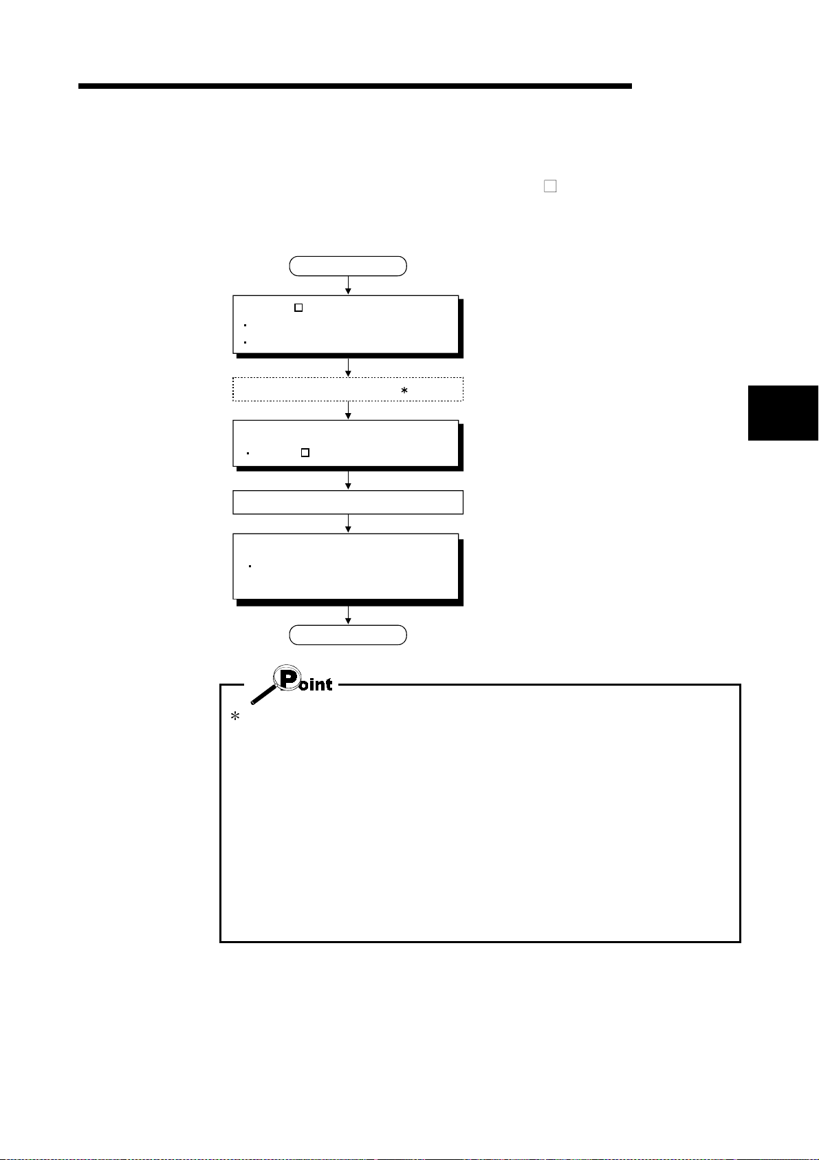
Installation procedure
START
Install SW D5C-QD75P-E.
Register your name and company name.
Register the product I/D.
Prepare the FD drive. 1
Install the license key FD.
Make SW D5C-QD75P-E valid.
MELSEC-Q
Refer to Section 4.1 (1).
4
Refer to Section 4.1 (2).
Store the license key FD.
Start the application.
Check whether it has been installed
properly.
FINISH
Refer to Section 4.3.
1: For a notebook computer designed to change a CD-ROM drive for an FD drive
and vice versa, make this change after installation of the application is
complete.
After the peripheral device has been restarted, the license key FD can be
installed.
Never perform the following operations for the license key FD.
The license key FD will be damaged if any of the following operations is performed.
• FD formatti ng
• File write onto the FD
• FD file copy (copy to other drive, copy from other drive)
• Deletion of file on the FD, file name changing, file attribute changing
• Running analysis tool (e.g. SCANDISK) for the FD
4 - 1
Page 31

4. INSTALLATION AND UNINSTALLATION
(1) Installing SW D5C-QD75P-E
The following explains how to install SW
MELSEC-Q
D5C-QD75P-E.
• Before startin g inst all at io n, clo se al l ot he r ap pli ca tio n s runn ing on Micr osof t
WindowsR Operating System.
R
• When the Operating System is Microso f t
WindowsNTR Workstation 4.0 Operating
System, log on as a user who has the attribute of an administrator (for computer
management).
1) Start Explorer and click the drive where the disk
is inserted.
Double-cli ck "Set up . e xe".
To display Explorer, choose [Start]
[Programs] [Windows Explorer].
R
When uninstallation has not been performed
(license invalid)
When uninstallation has not been performed
(license valid)
(To the next page)
When the message shown on the left has
appeared, click the "Cancel" button, uninstall
and then reinstall the product.
When the message shown on the left appears,
restore the license using the license key FD and
then install the product.
4 - 2
Page 32

4. INSTALLATION AND UNINSTALLATION
(From the pre cedi ng pa ge )
MELSEC-Q
2) Type your name and company name, and click
the "Next>" button.
As the confirmation dialog box appears, follow
the messages and perform operation.
3) Enter the product ID and click the "Next>" button.
The product ID is given on the "Software
Registrati on Car d" .
(To the next page)
4) Specify the installation destination folder.
After specifyin g th e install a ti on dest in atio n fo ld e r,
click the "Next>" button.
It defaults to "C:\MELSEC".
To change the destination folder, click the
"Browse..." button and specify a new drive and
folder.
4 - 3
Page 33

4. INSTALLATION AND UNINSTALLATION
(From the preceding page)
MELSEC-Q
5) This completes installation.
Now install the li cen se key FD and set the
product to valid status.
When the message shown on the left appears,
R
Windows
must be restarted.
• If installatio n fa il ed at any poin t in th e above p roc ed ure , unin st all an d rei n stal l th e
program.
Installing SW D5C-QD75P-E registers the icon as shown below.
4 - 4
Page 34

4. INSTALLATION AND UNINSTALLATION
(2) Installing the license key FD
The license key FD is designed to make SW
After installing SW
QD75P-E startable.
D5C-QD75P-E, in stall the license key FD to make SW D5C-
MELSEC-Q
D5C-QD75P-E valid.
1) Start Explorer and click the drive where the disk
is inserted.
Double-cli ck "Set up . e xe".
To display Explorer, choose [Start]
[Windows Explorer].
[Programs]
2) Click the picture of the lock.
3) Click the "Close" button.
(When the picture of the open lock appears,
SW
D5C-QD75P-E can be started.)
4 - 5
Page 35

4. INSTALLATION AND UNINSTALLATION
4.2 Uninstallat io n
MELSEC-Q
This section explains the operation for removing SW
D5C-QD75P-E from the hard
disk.
Uninstallation procedure
START
Uninstall the license key FD.
Make SW D5C-QD75P-E invalid.
Uninstall SW D5C-QD75P-E.
FINISH
Refer to Section 4.2 (1).
Refer to Section 4.2 (2).
• Uninstallation requires the same license key FD as used for installation.
4 - 6
Page 36

4. INSTALLATION AND UNINSTALLATION
(1) Uninstalling the license key FD
MELSEC-Q
1) Start Explorer and click the drive where the
license key FD is inserted.
Double-cli ck "Set up . e xe".
To display Explorer, choose [Start]
[Windows Explorer].
[Programs]
2) Click the picture of the open lock.
3) Click the "Close" button.
(When the picture of the closed lock appears, the
product is made invalid and can be uninstalled.)
4 - 7
Page 37

4. INSTALLATION AND UNINSTALLATION
(2) Uninstalling SW D5C-QD75P-E
MELSEC-Q
1) Double-click "Add/Remove Programs" on the
Control Panel.
To display the Control Panel, choose [Start]
[Settings] [Control Panel].
2) Choose "SWnD5-QD75P".
(To the next page)
3) Confirm that SW
removed.
Click "Yes" to start uninstallation.
Click "No" to return to the previous screen.
Components indicate the installed icon and file.
Unless you make SW
with the license key FD, the following dialog box
appears.
4 - 8
D5C-QD75P-E will be
D5C-QD75P-E invalid
Page 38

4. INSTALLATION AND UNINSTALLATION
(From the pre cedi ng pa ge )
MELSEC-Q
4) If the left screen has appeared, click the "No to
All" button.
If you choose "Yes" or "Yes to All", the shared
files for other MELSEC software packages are
removed. To remove only SW
therefore, click the "No to All" button.
5) When the "Uninstall completed" message
appears, click the "OK" button.
D5C-QD75P-E,
The completed message indicates that
uninstallation is complete.
4 - 9
Page 39

4. INSTALLATION AND UNINSTALLATION
4.3 Starting SW D5C-QD75P-E
MELSEC-Q
This section explains how to start SW
1) Move the cursor from [Start] [Programs]
2) Click [QD75WIN].
D5C-QD75P-E from the start menu.
[MELSEC Application].
3) SW D5C-QD75P-E starts.
4 - 10
Page 40

4. INSTALLATION AND UNINSTALLATION
4.4 Exiting SW D5C-QD75P-E
MELSEC-Q
This section describes how to exit SW
(1) Menu-driven exit method
Click the [Project]
SW
(2) Title bar-driven exit method
Click and choose [Close].
Alternatively, click
D5C-QD75P-E.
[Exit] menu.
D5C-QD75P-E ends.
at the right end of the title bar.
• In the online status such as the monitor or test mode, you cannot exit SW D5CQD75P-E.
In any of the following cases, end the program after choosing the offline status.
Monitor mode (refer to Section 10.2)
Test mode (refer to Section 10.4)
Online status for checking connect (refer to Section 7.4)
REMARK
When a new project has been created or a project has been modified but is not yet
saved, the confi rmat io n di al og bo x ap pe ar s to ask y ou whet he r you will save th at
project or not.
When you do not want to save it, click the "No" button.
When you want to save it, click the "Yes" button.
When you save a new project, choose [Save as Project].
For further information, refer to Section 6.1.
4 - 11
Page 41

4. INSTALLATION AND UNINSTALLATION
MEMO
MELSEC-Q
4 - 12
Page 42

5. SCREEN MAKEUP AND BASIC OPERATIONS
5. SCREEN MAKEUP AND BASIC OPERATIONS
This chapter explains the screen makeup and the display selection, window
arrangement and other operations of SW
5.1 Screen Make up and Display Selection
MELSEC-Q
D5C-QD75P-E.
Title bar
Menu bar
Toolbar
Online toolbar
Test toolbar
Project tr ee view
This section provides the screen makeup of SW
Drop-down menu
D5C-QD75P-E.
Screen minimize button
Screen maximize button
Online toolbar button
5
Window
(1) Display selection and window arr angement operations
You can use the following drop-down menu to choose to display or hide any
toolbar or arrange windows.
Menu Operation Description
[View] [Project tree view]
[Toolbar]
[Test toolbar]
[Online toolbar]
[View] [Status bar] Used to display or hide the status bar.
[View] [Select block start no]
[Window] [Cascade]
[Window] [Tile vertically] Used to lay multiple windows side by side.
[Window] [Arrange icons]
[Window] [All close] Used to close all open windows.
Used to display or hide the corresponding toolbar.
Used to choose any of block numbers 0 to 4 to be
displayed on the block start data edit window . (Refer to
Section 8.4.1)
Used to overlap multiple windows.
The above screen gives a cascade ex ample
Used to arrange windows which have been reduced to
small icons (minimized).
Status bar
5 - 1
Page 43

5. SCREEN MAKEUP AND BASIC OPERATIONS
k
5.2 Basic Operations
(1) Basic operation for project tree view
(a) Opening a window
The currently open project appears on the project tree view. Double-click the
project name or click
project name and press the "
Double-click the function name or click
keyboard, choose the function name and press the "
Double-cli c k the wi nd ow na me t o op en th at win dow.
(From the keyboard, choose the window name and press the "
to show its functions. (From the keyboard, choose the
" key.)
MELSEC-Q
to show the window types. (From the
" key.)
" key.)
Space
Double-click to
open window.
Double-click "SAMPLE". Double-click "Edit".
(b) Changing th e a c tiv e p ro je ct
Any online operation except for monitor, sampling (signal) monitor and
sampling (buffer) monitor is performed for the QD75 to which the active project
is connected, separately from the active window.
To change the active project, right-click the project name and click [Set Active
Project].
To perform online operation for "SAMPLE2", right-clic
project name and click [Set Active Project] menu.
(From the keyboard, choose "SAMPLE2" and press
"Ctrl" "R" keys.)
"SAMPLE2" appears in boldface type and is set as
the active projec t.
When multiple projects are open, confirm the active project before starting any
online operation except for monitor, sampling (signal) monitor and sampling (buffer)
monitor.
5 - 2
Page 44

5. SCREEN MAKEUP AND BASIC OPERATIONS
(2) Basic operation for dialog boxes
1) Tab
1) Tab
MELSEC-Q
Click the setting item name to select.
2) Text box
3) Command button
4) Radio button
5) List box
6) Check box
7) Spin box
2) Text box
Type numerals/characters.
3) Command button
Click this button when executing "OK", "Cancel"
etc., or when displaying the dialog box.
4) Radio but to n
Click
to choose one item among multiple
choices.
5) List box
Click
to list choices, then click the item to be
chosen.
6) Check box
To execute any item, click
to check it off.
7) Spin box
Used either to type a value directly or to change a
value by clicking
.
When typing a value directly, click inside the spin
box and enter the value from the keyboard.
When clicking
increase the value, or cl i ck
to change a value, click to
to decrease.
REMARK
When performing operation from the keyboard, choose the setting item with the
"Tab" key.
When there are two or more choices, use the "
5 - 3
", " ", " " and / or " " key.
Page 45

5. SCREEN MAKEUP AND BASIC OPERATIONS
(3) Moving the focus from the keyboard
Use the "Alt" key to move the focus to the drop-down menu.
Use the "F6" key to mov e t h e fo cu s betw e en th e p roje ct tr ee view and window
(edit, monitor, trace, checking connect).
(4) Shortcut key list
The following shortcut keys can be used with SW
MELSEC-Q
D5C-QD75P-E.
Shortcut
Key
Ctrl+N New project file Ctrl+Y Clear row —
Ctrl+O Open project file Ctrl+B Select block start no —
Ctrl+S Save Ctrl+T Write to QD75
Ctrl+G Change QD75 model
Ctrl+P Print Ctrl+F4 Close active window —
Ctrl+X Cut Ctrl+F6 Change active window —
Ctrl+C Copy F1 Help —
Ctrl+V Paste Change active window
Ctrl+A Select All —
Ctrl+J Jump —
Function (Corresponding Menu Item)
Tool
Button
—
Shortcut
Key
Ctrl+M Monitor On/Off
Alt+F4
Function (Corresponding Menu Item)
Exit/close dialog box
Tool
Button
—
(5) Tool button list
Toolbar
Type
Tool
Button
The following t abl e list s the t ool bu tt on s o f SW
Function (Corresponding Menu Item)
New project file
Toolbar
Type
Tool
Button
D5C-QD75P-E.
Function (Corresponding Menu Item)
Test On/Off
Toolbar
Online
toolbar
Open project file
Save
Cut
Copy
Paste Error reset #4
Print
Help (operation explanation)
Read from QD75
Write to QD75 M code off #4
Verify QD75
Monitor On/Off
Check QD75 data
Test
toolbar
All axis stop command
Error reset #1
Error reset #2
Error reset #3
M code off #1
M code off #2
M code off #3
Operation Test #1
Operation Test #2
Operation Test #3
Operation Test #4
Positioning data edit in test mode
Teaching
5 - 4
Page 46

6. PROJECT CREATION
6. PROJECT CREATION
A project is a collection of parameters, positioning data and block start data.
MELSEC-Q
Project
<SW
D5C-QD75P-E project makeup>
Parameters (Axis #1 to #4)
There are basic parameters 1, basic parameters 2, extended parameters 1,
extended parameters 2, OPR basic parameters and OPR extended parameters.
Positioning data (Axis #1 to #4)
Data used to set the control data such as positioning control method and addresses.
Data No. 1 to 600 can be set for each axis.
Block start data (Axis #1 to #4)
Data used to attach a condition to a positioning control start and set the repeat count.
Note: Equivalent to the start block data of the AD75 positioning module.
• When executing "New Project" or "Save as Project", you cannot set a space and
period in the project name to be specified. Further, you cannot set the following
characters and symbols.
/ , : ; * " < > | \\ COM LPT AUX CON PRN NUL CLOCK$
• You cannot set the following characters and symbols in a project path.
/ , : ; * " < > | \\ COM LPT AUX CON PRN NUL CLOCK$
6
6 - 1
Page 47

6. PROJECT CREATION
6.1 Creating a New Project Set the QD75 model used to create a new project and the project items.
MELSEC-Q
1) Click the [Project] [New Project] menu ( ).
2) Click the "Reference" button of the QD75 type in
the [New Project] dialog box.
3) Choose the Select type and Select Axis radio
buttons.
4) Click the "OK" button.
5) Set the project save path.
The project save path defaults to
C:\MELSEC\QD75P.
When changing it, refer to "HELPFUL
OPERATION (PART 1)" in this section.
6) Set the project name.
When specifying the project file name, you can
use a total of up to 150 characters to set the
project path and project name.
When setting the project path and project name,
the total number of characters should be within
150.
This screen assumes that the project name is
"Sample01".
7) Set the project title as required.
8) Click the "OK" button.
This creates a new project.
To utilize the data read from the QD75, refer to
"HELPFUL OPERATION (PART 2)" in this
section.
6 - 2
Page 48

6. PROJECT CREATION
HELPFUL OPERATION (PART 1)
You can perform the operation of changing the project save path while
simultaneously checking the project tree.
In step 5) on the preceding page, click the Project file set "Reference" button.
When the following dialog box appears, choose the project save path from the
project tree or type it from the keyboard.
This operation is also used to perform such operations as "Open Project", "Save
Project" and "Delete Project".
1) Choose the drive.
MELSEC-Q
Click the "New" button when creating a new project save path.
Type a new project save path.
2) Choose/type a new project save path.
3) Click.
• When saving a project, you cannot set "Untitled" in Project name.
Also, do not use "Untitled n (n: 1, 2, 3 .....)" in Project name.
If you read "Untitled 1" and create a new project in default setting, the same
project name (Untitled 1) appears on the Project tree view.
6 - 3
Page 49

6. PROJECT CREATION
HELPFUL OPERATION (PART 2)
When utilizing the data written to the QD75 to create a new project, perform the
following operation.
1. Set the QD75 type, project save path, project name and project title in the New
2. Click the "New Project read from unit" check box.
3. Click the "OK" button.
4. Click the "OK" button in the instruction dialog box.
5. Set the interface, I/O address and others in the Connection setup dialog box
6. Click the "OK" button.
7. Set the type an d rang e o f t h e da t a to be re ad in t he QD75 Re ad ing dial o g bo x
8. Click the "OK" button to read the positioning data, block start data and
<New QD75 readin g p roc ed ur e>
MELSEC-Q
Project dialog box.
(refer to Section 7.1).
(refer to Section 9.1).
parameters in the specified range from the QD75.
New project creation
Instruction is given to indicate
which QD75 model has precedence.
Connection setup (refer to Section 7.1)
Read from QD75 (refer to Section 9.1)
• When new project read from unit is performed for new project creation, the QD75
connected has precedence if the QD75 model of the project differs from the QD75
model connected.
After completi on of r ead in g, choo se the [P r o ject]
[Change QD75 model] menu
to change the model. (Refer to Section 11.1.2.)
6 - 4
Page 50

6. PROJECT CREATION
6.2 Opening the Existing Project
This section explains the operation of opening the saved project.
MELSEC-Q
1) Click the [Project] [Open Project] menu ( ).
2) Click the project name.
For the setting operation of referring to the project
save path, re fe r to "HEL P F UL OPE RA TI ON
(PART 1)" in Section 6.1.
3) Click the "O pe n" but to n.
4) The specified project opens.
5) To open multiple projects, repeat the operations in
steps 1) to 3).
The open projects are displayed on the project
tree view.
• Recently opened projects (files) can be opened from the
project menu
Up to four projects can be displayed.
Note that any projects not saved do not remain in the
project menu.
In the initial setting, the [Latest file] menu item appears.
6 - 5
Page 51

6. PROJECT CREATION
6.3 Saving the Project
MELSEC-Q
PURPOSE
The project file which is currently edited is saved.
BASIC OPERATION
1. Set the project to be saved as the active project. (Refer to Section 5.2.)
2. To perform save operation, click the [Project]
To perform save as operation, click the [Project]
When specifying the project file name, you can use a total of up to 150
characters to set the project path and project name.
When setting the project path and project name, the total number of characters
should be within 15 0.
For the operation of setting the project save path and project name, refer to
"HELPFUL OPERATION (PART 1)" in Section 6.1.
DISPLAY/SETTING SCREEN
[Save Project] menu ( ).
[Save as Project] menu.
HELPFUL OPERATION
You cannot use "Save as Project" to overwrite the same project name.
When you want to change the title in the same project name, perform the following
operation.
1. Double-click "Project information" on the Project tree view.
2. Click the unchecked "Modified title " check box in the Project information window
and change the current title.
3. Click the [P ro je ct]
• When saving a project, you cannot set "Untitled" in Project name.
Also, do not use "Untitled n (n: 1, 2, 3 .....)" in Project name.
If you read "Untitled 1" and create a new project in default setting, the same
project name (Untitled 1) appears on the Project tree view.
Save Project] menu.
[
6 - 6
Page 52

6. PROJECT CREATION
6.4 Closing the Project
MELSEC-Q
PURPOSE
The open project is closed.
BASIC OPERATION
1. Set the project to be closed on the project tree view.
2. Click the [P ro je ct]
3. If any setting has been changed, the dialog box appears to confirm whether the
project will be saved or not.
Click the "Yes" button to save and close the project.
Click "No" to close the project without saving it.
DISPLAY/SETTING SCREEN
[Close Project] menu.
6 - 7
Page 53

6. PROJECT CREATION
6.5 Deleting th e Pr o je ct
MELSEC-Q
PURPOSE
The project is deleted from HD, FD, etc..
BASIC OPERATION
1. Click the [P ro je ct] [Delete Project] menu.
2. In the Delete project file dialog box, choose the project you want to delete and
click the "Delete" button.
Refer to "HELPFUL OPERATION (PART 1)" in Section 6.1 for the operation of
changing the project save path.
3. As the project file deletion confirmation dialog box appears, click the "Yes"
button.
4. The project is deleted.
DISPLAY/SETTING SCREEN
6 - 8
Page 54

6. PROJECT CREATION
6.6 Reading Othe r Format F il e s
6.6.1 Reading SW1IVD-AD75P-E format file
PURPOSE
The positioning data, M code comments, block start data, condition data and
parameters are read from the file of the MELSEC-A series software package
(SW1IVD-AD75P-E, SW0D5C-AD75P-E) as a new project of SW
E.
BASIC OPERATION
1. Click the [P ro je ct] [Import file] [File reading of SW1IVD-AD75P]/[File
reading of SW0D5C-AD75P] menu.
2. Choose the file in the Open dialog box and click the "Open" button.
3. Click the "OK" button in the read destination confirmation dialog box.
4. Set the QD75 model, project save path, project name and project title in the
Other file type project dialog box. (Refer to Section 6.1 "HELPFUL
OPERATION (PART 1)".)
5. Click the "OK" button.
MELSEC-Q
D5C-QD75P-
DISPLAY/SETTING SCREEN
(The screen shows an example of SW0D5C-AD75P file read.)
DISPLAY/SETTING DATA
Item Description
Look in Choose the project save path of the file y ou will read.
File name Set the file name you will read.
Files of type SW1IVD-AD75P-E File (*.d75) or SW0D5C-AD75P-E File (*.w75) appears.
"Up One Level" button Click this button to show the folder one level above the currently display ed folder.
"List" button Click this button to list files and folders.
"Details" button Click this button to display the file and folder in detail.
"Open" button Click this button to read the file.
6 - 9
Page 55

6. PROJECT CREATION
• Since there are no four-axis type AD75 positioning modules, the positioning data,
block start data and parameters of the fourth axis are not read if the QD75 model
of the save destination project is of the four axis type.
• Note the following when the file in the SW1IVD-AD75P-E or SW0D5C-AD75P-E
format has been read .
Parameter
Positioning
data
Block start data
Indirect Data
: After file re ad ing, cond it io n data se tt in g i s need ed .
MELSEC-Q
Data Type Read to SW D5C-QD75P-E
Start bias speed
MPG
Over limit switch
Under limit switch
Drive unit ready
Stop signal
Output
pulse logic
selection
Stepping motor mode selection
Manual pulse generator
selection
ACC/DEC time unit selection
Near path control mode
MPG mode
Speed-position function selection
SLV axis
Positioning comment Not read from SW1IVD-AD75P-E.
External signal
Zero phase signal
Zeroing dog
MPG
DCC
Command pls
signal
Section is changed from basic parameter
2 to basic parameter 1
These are new items and therefore not
read. Default setting.
This name has been changed from the
pulse output logic selection to the drive
unit.
These are disused items and therefore
read-disabled.
These are disused items and therefore
read-disabled. (Because near path
control mode is fixed)
This is a new item and therefore readdisabled. Default setting.
This is a new item and therefore readdisabled. Default setting.
This name has been changed from the
start block data.
Because of reduction in number of
blocks, block numbers 5 to 10 are readdisabled.
"Stop" in special start is replaced by
"Wait start".
This is a disused item and therefore
read-disabled.
6 - 10
Page 56

6. PROJECT CREATION
6.6.2 Reading the CSV format file
PURPOSE
SW D5C-QD75P-E allows CSV format files created with spreadsheet software,
etc. be read as positioning data (axis #1 to #4). (Parameters and block start data
cannot be read.)
The creating method and reading operation of CSV format data are described
below.
• If all items that make up positioning data have not been entered, CSV format data
cannot be read, resulting in an error.
• Since CSV format data is read axis-by-axis, create CSV format data noting which
axis (#1/#2/#3/#4) data is being created.
MELSEC-Q
(1) CSV format data creating method
The following sheet indicates the items and values of CSV format data set on a
column basis.
<Example of data set to sp read she et so ftwa re>
2) 3) 4) 5) 6) 7) 8) 9) 10) 11) 1)
<Data set to the above spreadsheet software was read with SW D5C-QD75P-E>
Number Setting Remarks
1) Set the positioning control pattern in column 1 fro m left. Set any v alue from 0 to 2.
2) Set the operation method in column 2 from left. Set it w ith 1 to 9 and A to Z.
3) Set the interpolation axis for two-axis interpolation co ntrol in co lumn 3 fro m left.
4) Set the host axis for single-axis or three-/four-ax is interpolation control.
5) Set the accel time No. in column 4 from left. Set it from 0 to 3.
6) Set the decel time No. in column 5 from left. Set it from 0 to 3.
7) Set the address in column 6 from left.
8) Set the circular positioning address in column 7 from left.
9) Set the command speed in column 8 from left.
10) Set the dwell time in column 9 from left.
11) Set the M code in column 10 from left.
Refer to Section 8.2
for details of data
corresponding to
alphanumeric
values to be set.
6 - 11
Page 57

6. PROJECT CREATION
(2) CSV format file reading operation
BASIC OPERATION
1. On the project tree view ,set the active project whose CSV format file will be
2. Click the [Project]
3. Click the "Yes" button in the dialog box which confirms that the read CSV format
4. Choose the axis in the Object axis selection dialog box and click the "OK"
5. Choose the file an d fi le type in the Open dialo g bo x an d cli ck t he "Open" button.
6. Click the "OK" button in the read confirmation dialog box.
DISPLAY/SETTING SCREEN
[Object axis selection dialog box]
read. (Refer to Section 5.2.)
[Import file]
menu.
data will replace the present positioning data.
button.
[File reading of CSV form positioning data]
MELSEC-Q
[Open dialog box]
DISPLAY/SETTING DATA
Item Description
Object axis selection dialog
box
Look in Choose the project save path of the file y ou will read.
File name Set the file name to be read to the project.
Files of type CSV File (*.CSV) appears.
"Up One Level" button Click this button to show the folder one level above the currently display ed folder.
"List" button Click this button to list files and folders.
"Details" button Click this button to display the file and folder in detail.
"Open" button Click this button to read the file.
Choose the axis whose positioning data will be sav ed in the CSV format.
6 - 12
Page 58

6. PROJECT CREATION
6.7 Write to CSV Format File
MELSEC-Q
PURPOSE
The positioning data set in the project of SW D5C-QD75P-E is saved in the CSV
format file.
Refer to Section 6.6.2 (1) for the positioning data setting items and CSV format
data.
BASIC OPERATION
1. On the project tree view , set as the active project the project whose positioning
data will be saved in the CSV format file. (Refer to Section 5.2.)
2. Click the [P ro je ct]
menu.
3. Choose the axis in the Object axis selection dialog box and click the "OK"
button.
4. Set the save location and file name in the Save As dialog box and click the
"Save" button.
5. Click the "OK" button in the write confirmation dialog box.
[Export file ] [File writing of CSV form positioning data]
DISPLAY/SETTING SCREEN
[Object axis selection dialog box]
[Save As dialog box]
6 - 13
Page 59

6. PROJECT CREATION
MELSEC-Q
DISPLAY/SETTING DATA
Item Description
Object axis selection dialog
box
Save in Choose the drive or folder where the data will be saved.
File name Set the file name to be saved in the other format file.
Files of type CSV File (*.CSV) appears.
"Up One Level" button Click this button to show the folder one level above the currently display ed folder.
"Create New Folder"
button
"List" button Click this button to list files and folders.
"Details" button Click this button to display the file and folder in detail.
"Save" button Click this button to save the other format file.
Choose the axis whose positioning data will be sav ed in the CSV format.
Click this button to create a "new folder".
6 - 14
Page 60

7. SYSTEM CHECKING FROM PERIPHERAL DEVICE
7. SYSTEM CHECKING FROM PERIPHERAL DEVICE
Specify the QD75 to be accessed per project, also check connections with the external
equipment (servo amplifiers, servo motors, etc.), and conduct initial operation tests of
the servo motors.
7.1 Connection Setup
PURPOSE
Choose the interface connected to the QCPU or Q corresponding serial
communication module, and set the I/O address, etc. of the QD75 to be accessed.
BASIC OPERATION
1. Click the [Online] [Connection setup] menu.
2. Choose the interface in the Connection setup dialog box and set the I/O
address, etc.
3. After the setting is completed, click the "OK" button.
MELSEC-Q
Item Description
(Personal computer side)
Interface
COM
Baud rate
DISPLAY/SETTING SCREEN
7
DISPLAY/SETTING DATA
Choose the type of the personal computer side interface.
The selection range is RS232C or USB.
(This is fixed to RS-232C if C24 connection or remote I/O was selected as the PLC side
interface.)
Choose the COM port if the personal computer side interface is RS-232C .
The selection range is COM1 to COM10.
Choose the baud rate if the personal computer side interface is RS -232C.
The selection range is 9.6kbps to 115.2kbps.
7 - 1
Page 61

7. SYSTEM CHECKING FROM PERIPHERAL DEVICE
MELSEC-Q
Item Description
(PLC side)
Interface
PLC type
Multiple PLC setting
Network Not supported by this software package.
I/O address Set the I/O address (starting I/O number) of the QD75 to be accessed in hexadecimal.
Wait time
Timeout time Set the suspension time of communication judged as a com munic ation error.
Choose the type of the PLC to be connected.
Choose the CPU module, C24 connection, remote I/O or ladder logic test.
When the CPU module was selected as the PLC side interface, ch oose the ty pe of the
control PLC of the QD75 to communicate with.
When the CPU module was selected as the PLC side interface, ch oose the PLC No. of the
control PLC of the QD75 to communicate with in a multiple PLC sy stem conf iguration.
The selection range is Non-choice, PLC No. 1, PLC No. 2, PLC No. 3 and PLC N o. 4.
For a single PLC system configuration, choose "Non-choi ce".
Set the time-out period until the QD75 accepts a start or similar request from SW
QD75P. When time-out occurs, the operating axes all stop.
• If you set the personal computer interfaces to the same COM port in SW D5CQD75P-E and SW
D5C-GPPW-E, set the baudrate to the same speed.
If they are started at the same time, the baudrate set first has priority and the
baudrate set later is ignored.
• If SW
D5C-QD75P-E is forced to end in the test mode, a time-out occurs due to
the elapse of the wait time and the QD75 cancels the test mode.
• A communications error may occur if communications are made with the QCPU
after setting of any of the resume function, suspend setting, power-saving function
and standby mode of the peripheral device. For this reason, do not set the above
functions when communicating with the QD75.
• If the USB cable is disconnected/connected, the QCPU is reset, or power is
switched on/off frequently during communications with the QCPU, a
communications error may occur and the QD75 may not recover from the error.
Hence, place the QD75 offline when disconnecting/connecting the USB cable,
resetting the QCPU, or switching power on/off.
If the QD75 does not recover from the communications error, completely
disconnect the USB cable once and reconnect it after more than 5 seconds has
elapsed. (An error may occur at the initial communications after this operation, but
the QD75 will function properly from the second time onwards.)
• A communication error may occur depending on the combination of the personal
computer model, USB cable and so on.
In that case, refer to the message displayed and perform operation again.
• If the baudrate is changed at the serial port of the personal computer (personal
computer interface) to perform fast communication, communications may not be
made or a communications delay may occur due to a communications retry
depending on the performance of the personal computer.
If communications cannot be made for fast communication, reduce the baudrate
and restart communication.
D5C-
7 - 2
Page 62

7. SYSTEM CHECKING FROM PERIPHERAL DEVICE
REMARK
When the PLC interface is C24 connection (Q corresponding serial communication
module), the Q corresponding serial communication module switches must be set on
the PLC parameter I/O assignment setting screen of GPPW.
Refer to GPPW Operating Manual (function version of "4" or later), for the way to
make settings in the I/O assignment setting screen.
For more information on the switch settings, refer to "Q Corresponding Serial
Communication Module User's Manual (Basic Manual)".
Switch setting examples are listed below.
Item Description Setting
Switch 1 CH1 communication speed CH1 transmission setting 0726H
Switch 2 - CH1 communications protocol 0008H
Switch 3 CH2 communication speed CH2 transmission setting 0727H
Switch 4 - CH2 communications protocol 0000H
Switch 5 Module station number 0000H
MELSEC-Q
Detailed description of settings
Item Setting
Operation setting Independent setting
Data bit setting 8
Parity bit yes/no setting Yes
Odd/even parity bit Odd
Stop bit setting 1
Sum check yes/no setting Yes
Online change enable/disable setting Enable
Setting change enable/disable setting Disable
Transmission speed setting 19200bps
Communications protocol GPPW link
7 - 3
Page 63

7. SYSTEM CHECKING FROM PERIPHERAL DEVICE
7.2 System Monitor
PURPOSE
Check the module configuration, I/O address, QD75 model and axis statuses of
the station (system) connected.
BASIC OPERATION
1. Set the connection target. (Refer to Section 7.1.)
2. Click the [Tool]
3. The QD75 on the conn e ct e d st atio n ap pe a rs in th e Sy ste m mon i to r dial og bo x.
4. Click the QD75 illustration and check the I/O address, model and axis statutes.
5. To exit, click the "Close" button.
[System monitor] menu.
DISPLAY/SETTING SCREEN
MELSEC-Q
DISPLAY/SETTING DATA
Item Description
System monitor
QD75 Information Shows the I/O address, module type and module ax is statuses.
"Update" button Click this button to show the latest system information.
Shows the connection target PLC system.
Clicking the QD75 illustration shows the Q D75 module information.
7 - 4
Page 64

7. SYSTEM CHECKING FROM PERIPHERAL DEVICE
7.3 Checking the QD75 Function Version (OS Information)
PURPOSE
Depending on the function version of the QD75, this software may not be
compatible with some functions.(Refer to Section 1.3)
Before setting various data, check the function version (product information) of the
QD75 with the s e tt in g so ftware.
BASIC OPERATION
1. Specify the connection target. (Refer to Section 7.1.)
2. Click the [Online]
3. Check the function version in the OS information dialog box.
4. To exit, click the "Close" button.
[OS information] menu.
DISPLAY/SETTING SCREEN
MELSEC-Q
DISPLAY/SETTING DATA
Item DISPLAY/SETTING SCREEN
Connected type Indicates the model of the connected QD75.
Product information
Indicates the function version of the connected QD75. T he function v ersion "B" i s disp lay ed
on the above display/setting screen.
7 - 5
Page 65

7. SYSTEM CHECKING FROM PERIPHERAL DEVICE
7.4 Checking Connect
PURPOSE
Make sure that the cables between QD75 and servo amplifiers and between servo
motors, servo amplifiers and external devices are connected properly.
BASIC OPERATION
1. Power on the positioning system and STOP the PLC CPU.
2. Set the connection target. (Refer to Section 7.1.)
3. Choose Checking connect.
¨
Double click Double click
4. Click the "Online" button in the Checking connect window.
5. The online processing (test mode shift) confirmation dialog box appears.
Click the "Ini ti aliz e" bu tt on to che ck con ne cti on aft e r ini ti aliz in g t he QD75 .
Click "OK" to check connection without initializing the QD75.
6. Make sure that the external I/O signals are in the following states.
Drive unit ready, Upper limit, Low er li mit : ON (r ed)
Stop signal : OFF (gr ay )
If any of the above states is not established, refer to "HELPFUL OPERATION
(1)" and "HELPFUL CORRECTIVE ACTIONS" in this section.
7. Check whether the following signals from the external devices are ON or OFF.
Stop signal, External command.
8. Set the JOG speed.
9. Press the "FWD" or "REV" button to start JOG operation.
Hold down the button to continue JOG operation.
10. Perform JOG operation and check the operation, rotation direction and feed
speed of the servo motor.
11. Perform JOG operation and check whether Zero phase and DOG signals turn
on or off.
12. Perform JOG operation and check whether the upper and lower limit switches
turn on or off.
Refer to "HE LPFUL OPERATION ( 2 )" in thi s s e ction for the way to re st o re an
axis stop due to OFF of the upper/lower limit switch.
13. When an error has occurred, check the error code definition with the help
function (refer to Section 11.10), then click [Online]
[Error Reset #1 to #4] menu ( to ).
14. To exit, click the "Offline" button, and click the "OK" button in the test mode
end confirmation dialog box.
[Test]
MELSEC-Q
[Error Reset]
7 - 6
Page 66

7. SYSTEM CHECKING FROM PERIPHERAL DEVICE
DISPLAY/SETTING SCREEN
MELSEC-Q
DISPLAY/SETTING DATA
Item Description
Operation monitor Indicates the feed present value, feed spee d, error No. and warning No. of each axis.
JOG speed Set the speed for JOG operation.
JOG direction Press the "FWD" or "RVS" button of the axis for JOG operation to start JOG operation.
External I/O Indicates the external I/O signal states (ON: Red, OFF: G ray) of the QD75.
"Offline" button Click this button to end the Q D75 test mode and end Checking connect.
"Online" button Click this b utton to start the Q D75 test mode and execute Checking connect.
7 - 7
Page 67

7. SYSTEM CHECKING FROM PERIPHERAL DEVICE
HELPFUL OPERATION (1)
Perform the following operation if the I/O logic states of the drive unit ready,
upper/lower limit switch and stop signal are different from the initial settings
(negative logic).
1. In the extended parameters, set the logic signals in which the following states
are established during normal operation. (Refer to Section 8.1.)
Drive unit ready , up per limit , low e r li mit : ON
Stop signal: OF F
2. Write the parameters to the QD75. (Refer to Section 9.1.)
3. Perform steps 1 to 5 in the basic operation of this section.
4. Click the "No" button in the QD75 initialization confirmation dialog box.
5. The operation steps to be performed hereafter are the same as steps 7 to 14 in
the basic operatio n o f th i s secti on .
HELPFUL OPERATION (2)
MELSEC-Q
Perform the following operation to restart the axis which was brought to an alarm
stop as the upper/lower limit switch had turned OFF during JOG operation.
1. Click [Online]
[Test]
[Error Reset]
[Error Reset #1 to #4] menu (
).
2. Perform JOG opera tio n to mov e the axi s to wit hi n the uppe r o r lowe r li mit rang e .
HELPFUL CORRECTIVE ACTIONS
Take the following basic corrective actions when Checking connect cannot be
completed properly.
Status Corrective Action
Checking connect cannot
start
Drive unit ready signal is
OFF
Upper/lower limit signal is
OFF
JOG operation cannot be
performed.
Error/warning occurred Check the error/warning code using the help function, and remov e the caus e.
Check the connection of cables with the QD 75.
In Connection setup, check whether the interface, CPU ty pe and other settings are correct.
(Refer to Section 7.1.)
Check that the servo amplifier is powered on.
Check the connection of the external I/O signal connector.
Change the extended parameter I/O logic.
Check the connection of the external I/O signal connector.
Check for contact of the upper/lower limit switch.
Change the extended parameter I/O logic.
Check the connection of the external I/O signal connector.
Check the status of the stop switch.Stop signal is ON
Change the extended parameter I/O logic.
Check that JOG speed setting is not "0".
to
7 - 8
Page 68

8. DATA SETTING
8. DATA SETTING
8.1 Parameter Setting
MELSEC-Q
Set the parameters, positioning data and block start data to be written to the QD75,
and check the setting ranges and matching of the data using the simulation or error
check function.
Write the preset parameters, positioning data and block start data to the QD75 before
starting posit ion in g op era ti o n.
Refer to Section 9.1 for the operation to write the data to the QD75.
Set the parameters necessary to exercise positioning control.
For the setting data, refer to the QD75 user's manual.
PURPOSE
There are the following four parameter types.
• Basic parameters
• Extended parameters
• OPR basic parameters
• OPR extended parameters
The basic and extended parameters are divided into parameters 1 needed for
system start and parameters 2 optimized according to the connected external
devices and control.
BASIC OPERATION
1. Choose Parameter.
¨
Double click
2. Make setting in the parameter edit window.
Double click
8
8 - 1
Page 69

8. DATA SETTING
MELSEC-Q
DISPLAY/SETTING SCREEN
Double-click the cell and make setting in the text box or list box.
In the text box, you can set the maximu m va lue/ min i mum va lu e/ de fa ul t valu e wi th
the right-click menu.
When performing operation from the keyboard, enter the value and press the
"Enter" key to determine the value.
In the list box which shows the set value and set data (example 3:pulse), pressing
the "space" key displays a list.
Make selection with th e "
value.
• In the paramet e r edi t wind ow, th e in di cat ion s hav e the fol low i ng mea ni ng s.
Blue chara cte r s : Defaul t (i ni tial value) se tt in g
Black characters : Setting other than default (no error)
Red : Setting range error
• Since changing the unit setting changes the setting range, any setting other than
the default (black characters) may result in a setting range error.
After changing the unit setting, make an error check to confirm the setting.
" or " " key, and press the "Enter" key to determine the
"Space" key
8 - 2
Page 70

8. DATA SETTING
8.2 Positioning Data Setting
This section describes the positioning data setting, the addition of circular interpolation
control to the po si tioni ng da t a by spe ci fy ing a sub po in t , and sp ee d se tt in g u sing the
axis speed calculation function.
This section also explains the M code comment setting in which the M codes assigned
to the positioning data are annotated with comments.
8.2.1 Positioning data
MELSEC-Q
PURPOSE
Set the positioning data such as the operation pattern, control method, SLV axis,
acceleration time No., deceleration time No., address and command speed.
For details of the positioning data, refer to QD75 User's Manual.
BASIC OPERATION
1. Choose the axis to which the positioning data will be set.
Double click
2. Set the data in the positioning data edit window.
Double click
DISPLAY/SETTING SCREEN
Double-click the cell and make setting in the text box or list box.
For "SLV axis", choose it from the SLV axis set dialog box when the control
method is 2-axis interpolation control.
When performing operation from the keyboard, enter the value and press the
"Enter" key to determine the value.
For "Pattern', "CTRL method", "ACC" and "DEC", press the "space" key to display
a list.
Make selection with th e "
value.
" or " " key, and press the "Enter" key to determine the
8 - 3
Page 71

8. DATA SETTING
Item Description
No.
Pattern
CTRL method
MELSEC-Q
DISPLAY/SETTING DATA
Indicates the No. of the positioning data.
The positioning data that can be ranges from No. 1 to 600.
However, No. 1 to 100 are displayed in the initial setting.
To change the display range, use the option function (refer to Section 11.5).
Choose the operation pattern for positioning control.
The selection range is 0 to 2.
0: END (End command) 2: LO CU S (continue locus pos itioning control)
1: CONT (continue positioning control)
Choose the operation positioning control method from among 1 to 9 and A to Z.
1: ABS line 1 (Axis #1 Line interpolation (ABS))
2: INC line 1 (Axis #1 Line interpolation (INC))
3: Feed 1 (Axis #1 Fixed distance feed control)
4: FWD velocity 1 (Axis #1 Velocity control (Forward))
5: RVS velocity 1 (Axis #1 Velocity control (Reverse))
6: FWD V/P (Velocity/Positioning change control (Forward))
7: RVS V/P (Velocity/Positioning change control (Reverse))
8: FWD P/V (Positioning/Velocity change control (Forward))
9: RVS P/V (Positioning/Velocity change control (Reverse))
A: ABS line 2 (Axis #2 Line interpolation (ABS))
B: INC line 2 (Axis #2 Line interpolation (INC))
C: Feed 2 (Axis #2 Fixed distance feed control)
D: ABS ArcMP (Sub point setting arc interpolation control (ABS))
E: INC ArcMP (Sub point setting arc interpolation control (INC))
F: ABS ArcRGT (Center point setting arc interpolation control (ABS/CW))
G: ABS ArcLFT (Center point setting arc interpolation control (ABS/CCW))
H: INC ArcRGT (Center point setting arc interpolation control (INC/CW))
I: INC ArcLFT (Center point setting arc interpolation control (INC/CC W))
J: FWD velocity 2 (Axis #2 Velocity control (Forward))
K: RVS velocity 2 (Axis #2 Velocity control (Reverse))
L: ABS line 3 (Axis #3 Line interpolation (ABS))
M: INC line 3 (Axis #3 Line interpolation (INC))
N: Feed 3 (Axis #3 Fixed distance feed control)
O: FWD velocity 3 (Axis #3 Velocity control (Forward))
P: RVS velocity 3 (Axis #3 Velocity control (Reverse))
Q: ABS line 4 (Axis #4 Line interpolation (ABS))
R: INC line 4 (Axis #4 Line interpolation (INC))
S: Feed 4 (Axis #4 Fixed distance feed control)
T: FWD velocity 4 (Axis #4 Velocity control (Forward))
U: RVS velocity 4 (Axis #4 Velocity control (Reverse))
V: NOP (NOP command)
W: Address CHG (Address change)
X: JUMP (JUMP command)
Y: LOOP (Start loop point)
Z: LEND (End loop point)
8 - 4
Page 72

8. DATA SETTING
MELSEC-Q
Item Description
Set the interpolation axis when the control method is linear interpolation control (2 axes) or
SLV axis
ACC
DEC
Positioning address
Arc Address Set the address of the sub point or center point designated for circular interpolation co ntrol.
Command speed
Dwell time
M code
Positioning comment
circular interpolation control.
Use the SLV axis set dialog box.
Choose the ACC time or DEC time from among 0 to 3 and set in the basic para meters 2 an d
extended parameters 2.
Set the address for the absolute system or the travel distance for the incremental system.
Set a new current value when the control method is an address change.
Set the command speed for positioning.
Set the command speed to "-1" to exercise control at the current spe ed.
• Control method is other than "JUMP"
Set the delay time till the next positioning data completion in the range 0 t o 65535m s.
• Control method is "JUMP"
Set any position from No. 1 to 600 of the JUMP destination.
• Control method is other than "JUMP" or "LOOP"
Set the M code used to perform work, process, etc. in synchronization with positioning
control in the range 1 to 65535.
• Control method is "JUMP"
Set any of the condition data No. 1 to 10 which is used as the JUMP command execution
condition.
Setting of the condition data whose condition operator is "Simultaneous ly start axis set" is
invalid.
Set "0" to execute the JUMP command unconditionally .
• Control method is "LOOP"
Set the repeat count within the range 1 to 65535.
Assign a comment per positioning data.
You can set a comment of up to 32 characters.
• The colors of th e cel l s (li st ) in t he po si ti oni ng da ta edi t wi ndow have the followi ng
meanings.
Yellow : Setting must not be made since the data is on the interpolation axis
side of interpol at io n co ntr ol .
Red : Item needing setting is not yet set or is in error.
Gray : Setting need not be made (setting value is invalid).1)
8 - 5
Page 73

8. DATA SETTING
MELSEC-Q
HELPFUL OPERATION (1)
When you want to use a smooth arc (curve) on an intersection of two consecutive
linear interp ol at io n cont r ol s, y ou can pe rfo rm th e fol low i n g oper at ion t o in se rt th e
circular interpolation control positioning data between the linear interpolation
controls.
Target position
Target position
Data No. 2
(2-axis linear
interpolation control)
Data No. 1
(2-axis linear
interpolation
control)
1. Open the positioning data edit window of the reference axis to which sub arc
setting will be made.
2. Click the [E dit]
3. Set "Data" and "SubArc Radius" in the SubArc Setting dialog box.
4. Click the " Calculation " button.
5. The positioning data overwrite confirmation dialog box appears. Click the "OK"
button.
<Sub arc setting example>
Starting position
[Sub arc] menu.
Data No. 3
(2-axis linear interpolation control)
Arc radius
Starting position
Data No. 2
(Circular interpolation control)
Data No. 1
(2-axis linear interpolation control)
• Open the positioning data edit window of axis 1 which
is used as the reference axis.
• Click the [Edit]
[Sub arc] menu.
• Set "1" to "Data" and "50" to "SubArc Radius".
• Click "OK" in the positioning data overwrite dialog box.
• The address of dat a No. 1 i s chan ged an d da ta No . 2
changes to circular interpolation control data.
The original data of data No. 2 is set to data No. 3.
• Since the selected No. and next No. are overwritten by the positioning data
created in sub arc setting, leave the next No. as NOP (empty).
• In either of the following cases, you cannot make sub arc setting.
The control method is other than 2-axis linear interpolation control or fixeddistance feed 2.
Positioning data setting is in error.
8 - 6
Page 74

8. DATA SETTING
MELSEC-Q
HELPFUL OPERATION (2)
Perform the following operation when you want to determine the command speed
from the time needed to complete positioning. Use the axis speed calculation
function to calculate the command speed from the travel distance, acceleration
time, deceleration time, time needed for positioning completion and so on.
1. Open the positioning data edit window of the corresponding axis. (Active status)
2. Click the [E dit]
3. Set the Rati ng , Feed ba ck, S t a rt po siti on , En d po sit io n, Ope r at ion in te rv al and
Data No. in the Axis speed calculation dialog box, and choose ACC interval and
DEC interval.
4. Click the "Calculation" button to show the operation result in the Confirmation
dialog box.
5. Click "OK" in the Confirmation dialog box to change the command speed to that
of the operation result.
[Axis speed calculation dialog box]
[Speed of axis setting] menu.
[Confirmation dialog box]
• Axis speed calculation is to be made for the control method of 1-axis linear control
(ABS).
• If the axis speed calculated exceeds the speed limit value, setting it to the
positioning data will result in an error.
• You cannot perform axis speed calculation if the set number of pulses output
exceeds the performance of the QD75.
For QD75P1/P2/P4 (open collector output type)
Number of output pulses ((rated speed)
200kpps
For QD75D1/D2/D4 (differential driver output type)
Number of output pulses ((rated speed)
1Mpps
(number of feedback pulses) / 60) ≤
(number of feedback pulses) / 60) ≤
8 - 7
Page 75

8. DATA SETTING
8.2.2 M code comment
MELSEC-Q
PURPOSE
Set comments to M codes which are required for control exercised in
synchronization with positioning control.
M code comments are data which can be saved only in the personal computer.
Up to 50 comments can be set for each axis.
BASIC OPERATION
1. Choose the positioning data of the axis to which the M code comments will be
set.
Double-click.Double-click.
2. Click the [E dit]
3. Set the M code comments.
4. To exit, cli c k the "OK" but t o n in th e M co de commen t di al og bo x.
[M code comment] menu.
DISPLAY/SETTING SCREEN
DISPLAY/SETTING DATA
Item Description
M code Set the M code No. to be commented.
M code comment
"OK" button Click this button to finish the setting.
"Delete" button Click this b utton to delete t he sele cted comment.
Set a comment of up to 32 characters.
Up to 50 comments can be set for each axis.
8 - 8
Page 76

8. DATA SETTING
8.3 Simulation
MELSEC-Q
PURPOSE
Execute simul ati o n (vi r tu al po si tio ni ng ) wi th the set po sit i onin g dat a to che ck th e
operation of the axis.
The axis speed is displayed as locus data for 1-axis control or as locus data for 2axis interpolation control.
You cannot perform simulation for 3-/4-axis interpolation control.
BASIC OPERATION
1. Open the posit io ni ng dat a ed it wi nd ow .
Double-click.Double-click.
2. Click the [E dit] [Simulation] menu.
3. Type the fi r st No. of p o si ti o n in g da ta in the si mul a tion window.
4. Setting or changing the positioning data being simulated in the positioning data
edit window show s th e si mul at io n re sult at th e po in t of d ata inp ut .
5. To exit, click the "CLOSE" button.
DISPLAY/SETTING SCREEN
[Locus data for 1-axis control]
8 - 9
Page 77

8. DATA SETTING
MELSEC-Q
[Locus data for 2-axis interpolation control]
Item Description
Positioning start No.
Scaling
"Fixed ratio" check box
Time/Speed
(Waveform data)
#1 to #4 axis coordinates
(Locus data)
Simulation result
DISPLAY/SETTING DATA
Set the first positioning data No. from which simulation starts.
Simulation is performed on the data from the specified No. to the "End" of the operat ion
pattern.
Used to enlarge or reduce the simulation result in the vertical and horizontal dire ctions.
Moving the side to the right enlarges the result.
Click the unchecked check box to enlarge/reduce the resu lt in the v ertical an d horiz ontal
directions by the same ratio.
Shows the time and axis speed at the position clicked in th e sim ulation re sult dis play .
Shows the coordinates at the position clicked in the simulat ion result d ispl ay .
In the screen example, the coordinates shown are those of Axis #1 used as the reference
axis and Axis #2 used as the interpolation ax is.
Shows the simulation result.
Changing the positioning data also changes the simulatio n result in synchronization.
For 2-axis interpolation control, the reference axis is in the horizontal direct ion and the
interpolation axis is in the vertical direction.
For 1-axis control, time is in the horizontal direction and the ax is speed is in the vertical
direction.
Use the scroll bars to move the display area.
8 - 10
Page 78

8. DATA SETTING
MELSEC-Q
REMARK
In the locus dat a for ci rcul a r int e rpol at io n co ntr ol , line s may be bro ken due t o a da ta
processing error during drawing.
HELPFUL OPERATION
When you want to try the command speeds (waveform) or addresses (locus) at
the setting of the positioning data, you can set or change the positioning data while
simultaneously checking the simulation result.
8 - 11
Page 79

8. DATA SETTING
8.4 Block Start Data Setting Set the block sta r t da ta fo r cont r oll in g a positioning start and the con di ti o n data u sed as
a condition for a special start.
• The block start data is equivalent to the start block data of the AD75.
8.4.1 Block start data
MELSEC-Q
PURPOSE
Specify the positioning data No. as a point, and set the block start data which sets
the starting condition, execution order and execution count to each point.
You can set up to 50 points per block.
There are blocks No. 0 to 4 per axis.
BASIC OPERATION
1. Choose the block start data.
Double-click. Double-click.
2. Make settings in the block start data edit window.
DISPLAY/SETTING SCREEN
Double-cli ck the cell and make se t ti ng s in the t e xt bo x or li st bo x.
When performing operation from the keyboard, enter the value and press the
"Enter" key to determine the value.
For "Pattern" and "Special start", press the "space" key to display a list.
Make selection with th e "
value.
" or " " key, and press the "Enter" key to determine the
8 - 12
Page 80

8. DATA SETTING
DISPLAY/SETTING DATA
Item Description
Point No. Shows the point numbers 1 to 50.
Pattern
Data No.
Special Start
Param
Condition data
Select whether positioning control is ended at the point w here positioning w as completed or
positioning control will be continued to the next point.
Set the positioning data No. specified at the point.
The setting range is positioning data No. 1 to 600.
Choose the type of positioning control start per point.
The selection range is 0 to 6.
0: Normal start
1: COND start
2: Wait start
3: SIMU start
4: FOR loop
5: FOR condition
6: NEXT start
For the special start information, refer to QD75 User's Manual.
When you set a conditional start, wait start, simultaneous start or FO R condition in Special
Start, set any of the condition data No. 1 to 10 as its condition. (Refer to Section 8.4.2.)
When you set FOR loop in Special Start, set the repeat count.
The setting range is 0 to 255.
Setting "0" makes the repeat count limitless.
When you set a conditional start, wait start, simultaneous start or FO R condition in Special
Start, the data of the parameter-set condition data No. appears.
Double-clicking opens the condition data edit dialog box.
When you set FOR loop in Special Start, the "repeat count" appears.
Nothing appears when you set a normal start or NEXT start in Special Start.
MELSEC-Q
HELPFUL OPERATION
The block start data to be edited defaults to block No. 0.
Perform the fo ll ow ing op e ra t i on to change th e block to be edited to any of block
No. 1 to 4.
1. Open the blo c k sta rt da t a e di t win dow.
2. Click the [V iew]
3. Choose the block to be edited in the Block No. change dialog box, and click
"OK" button.
[Select block start data no] menu.
8 - 13
Page 81

8. DATA SETTING
8.4.2 Condition data
MELSEC-Q
PURPOSE
Set the condition data which will be the starting conditions of the conditional start,
wait start, simultaneous start and FOR condition in the block start data.
BASIC OPERATION
1. Choose the block start data of the axis to which the condition data will be set.
Double-click. Double-click.
2. Click the [E dit]
3. Choose the data No. to be set in the Condition data list dialog box.
4. Click the "Edit " bu t to n in the Co nd it io n da ta l i st dia lo g bo x.
5. Choose the condition operator and condition identifier in the Condition data edit
dialog box, and set the condition values.
6. Click the "OK" button in the Condition data edit dialog box.
7. To exit, click the "Close" button in the Condition data list dialog box.
[Condition dat a ed it ] men u.
DISPLAY/SETTING SCREEN
[Condition data list dialog box]
[Condition data edit dialog box]
8 - 14
Page 82

8. DATA SETTING
DISPLAY/SETTING DATA
Item Description
No. Shows the condition data No.
Condition data Shows the condition data set in the Condition data edit dialog box.
"Edit" button Click this button to display the Condition data edit dialo g box.
"Delete" button Click this b utton to delete t he cond ition data at the cursor.
Choose the type of the condition operator of the condition data.
=P1
•
•
!=P1
• <=P1
=>P1
•
• P1<= <=P2
Condition operator
Condition identifier
Text box
"OK" button By clicking this button, the settings appear in the Condition data list dialog box.
• <=P1, P2<=
• Device=ON
• Device=OFF
• Simultaneous start axis set
indicates the value stored in buffer memory.
P1 and P2 indicate parameters (values set as desired).
Device indicates the X/Y device.
Choose the object of the condition operator.
• If the condition operator is comparison between and P1 and/or P2
Choose the buffer memory size of 16 or 32 bits.
• If the condition operator is device=ON/OFF
Choose the device type of X device or Y device.
• If the condition operator is simultaneous start, choose the axes to be started at the same
time.
Set the condition object to the condition operator.
• If the condition operator is comparison between
Set the buffer memory address in .
Set to P1 and/or P2 the value of the size set in Condition identifier.
• If the condition operator is device=ON/OFF
Set the device name.
• If the condition operator is simultaneous start
Set the positioning data No. of the axes to be started at the same time.
and P1 and/or P2
MELSEC-Q
HELPFUL OPERATION
When setting the condition data consecutively, click in the Condition data
edit dialog box.
Since this causes the Condition data edit dialog box to be kept open if you click the
"OK" button, you can edit the condition data by switching it to the Condition data
list dialog box.
8 - 15
Page 83

8. DATA SETTING
8.5 Error Check
MELSEC-Q
PURPOSE
Make error check to check the parameter settings, positioning data and block start
data for mismatches and setting omissions.
For the error check range, refer to QD75 User's Manual.
BASIC OPERATION
1. Set the error-checked project as the active project on the project tree view.
(Refer to Section 5.2.)
2. Click the [Tool]
DISPLAY/SETTING SCREEN
[Error check] menu.
DISPLAY/SETTING DATA
Item Description
Error check item In the check box, set the data on which error check will be made.
"Check" button Click this button to start error check.
"Jump" button Click this button to show the error locations.
When error check is completed, the number of errors and error locations ap pear.
Error check result
On the above screen, error locations are the command speed of axis #1 positioning data No.
7 and the parameter at point No. 1 of axis #1 block No. 0.
8 - 16
Page 84

9. QD75 DATA WRITE/READ/VERIFY
9. QD75 DATA WRITE/READ/VERIFY
Perform write to QD75/read from QD75/verify QD75 data, data write from QD75 buffer
memory to flash ROM, and QD75 initialization.
MELSEC-Q
QD75
Buffer memory
Via QCPU, Q corresponding serial
communication module or
Q corresponding MELSECNET/H
network remote I/O module
:Only when connecting to the
remote I/ O module directry.
Write to QD75/read from QD75/
verify QD75 data
Write to flash ROM
9.1 Write to QD75/Read from QD75/Verify QD75 Data
PURPOSE
Write, read and verify the data set in the project (parameters, positioning data,
block start data) on an axis by axis basis.
Parameters
Positioning data
Block start data
Flash ROM
Parameters
Positioning data
Block start data
• Write to QD75 executes a write to the QD75 which is set in the active project.
When performing batch write to multiple QD75s, use the multi-module batch write
function. (Refer to Section 11.1.4)
• Whether write to QD75 may be performed or not is determined by the PLC state
check setting in Option setting. (Refer to Section 11.5)
• When trying operation while simultaneously changing the positioning data, you can
use the positioning data test edit function to write only the positioning data during a
test. (Refer to Section 11.7.2)
BASIC OPERATION
1. Place the QCPU in the STOP status.
When performing write to QD75 without putting the QCPU in the STOP status,
change the PLC state check setting in Option setting.
2. As an active project, set the project used for write to QD75/read from
QD75/verify QD75 data. Refer to Section 5.2 for the active project setting.
3. Click the [Online]
QD75 data] (
4. Set the data type and range in the QD75 Writing/Reading/Verify dialog box.
5. Click the "OK" button to start operation.
6. For QD75 data verify, the verify result appears.
[Write to QD75] (
) menu.
9 - 1
)/[Read from QD75] (
)/Verify
9
Page 85

9. QD75 DATA WRITE/READ/VERIFY
DISPLAY/SETTING SCREEN
<Write form QD75>
<<Main>> tab screen
<<Positioning data>> tab screen
MELSEC-Q
<<Block start data>> tab screen
<<Parameter data>> tab screen
9 - 2
Page 86

9. QD75 DATA WRITE/READ/VERIFY
<Verify QD75 da ta>
[Verify result di alo g bo x]
DISPLAY/SETTING DATA
Item Description
Positioning data
Block start data
Parameter
"Flash-ROM write" check
box
Current type
<<Positioning data>> tab
<<Block start data>> tab
<<Parameter data>> tab
<<Positioning data>> tab
screen
<<Block start data>> tab
screen
<<Parameter data>> tab
screen
"OK" button Click this button to start write to QD75/read from QD75/verify QD75 data.
Verify result dialog box
Set the data used for write to QD75/read from QD75/verify QD75 data from position ing data,
block start data and parameters.
Block start data includes condition data.
When performing write to QD75, set a request to write from buffer memory to flash RO M at
the same time.
Set the model of the QD75 connected to the peripheral device and the range of
write/read/verify.
Click the corresponding tab to display the screen w hich is u sed to set th e axes and ranges of
the data for write to QD75/read from QD75/verify QD75 data.
Set the axes of the positioning data used for write to QD75/read from Q D75/verify QD75
data.
Also, set the positioning data No.s in the write/read/v erify range on an axis by axis basis.
Set the axes of the block start data used for write to QD75/read from Q D75/verify QD75 data.
Also, set the range of the QD75 write/read/verify block on an ax is basis.
Set the axes used for write to QD75/read from QD75/verify QD75 data.
After QD75 data verify is completed, differences between the QD75 and project appear.
The screen displays that the speed limit value of the ax is #1 basic p arameter 2 and the
software stroke limit upper/lower limit value of the extended parameter 1 differ between the
QD75 and project.
Verify processing is suspended as soon as the numb er of mism atche s reache s 600.
MELSEC-Q
• The following data are saved in the peripheral device only and write to QD75/read
from QD75/verify QD75 data cannot be performed.
M code comments
Positioning data comments
9 - 3
Page 87

9. QD75 DATA WRITE/READ/VERIFY
9.2 Flash ROM write request
PURPOSE
Issue the command to write the QD75 buffer memory data to the flash ROM.
Write from buffer memory to flash ROM is batch-performed in the full ranges of the
parameters, positioning data and block start data (including condition data).
• Whether the flash ROM request may be performed or not is determined by the
PLC state check setting in Option setting. (Refer to Section 11.5)
BASIC OPERATION
1. Place the QCPU in the STOP status.
When performing the flash ROM write request without putting the QCPU in the
STOP status, change the PLC state check setting in Option setting.
2. On the project tree view, set the required project as an active project. (Refer to
Section 5.2)
3. Click the [Online]
4. Click the "Action" button in the Flash ROM request dialog box.
5. Click the "Yes" button in the execution confirmation dialog box.
[Flash ROM request] menu.
MELSEC-Q
9.3 QD75 Initialization
PURPOSE
When the system is renewed, for example, initialize the QD75 flash ROM and
buffer memory to place them in the factory-set status (default settings).
• Whether QD75 initialization may be performed or not is determined by the PLC
state check setting in Option setting. (Refer to Section 11.5)
BASIC OPERATION
1. Place the QCPU in the STOP status.
When performing QD75 initialization without putting the QCPU in the STOP
status, change the PLC state check setting in Option setting.
2. On the project tree view, set the required project as an active project. (Refer to
Section 5.2)
3. Click the [Online]
4. Click the "Acti on" bu tt on in t he Ini ti aliz e QD75 dia lo g b ox.
5. Click the "Yes" button in the execution confirmation dialog box.
[Initializ e QD7 5] men u.
9 - 4
Page 88

10. POSITIONING DEBUGGING
10. POSITIONING DEBUGGING
Debug positioning operation by checking the parameters, positioning data and other
data set to the QD75 for errors, monitoring the positioning operation, and performing
various operation tests by positioning data test operation and JOG operation.
• All axes stop if a communications error occurs, e.g. SW D5C-QD75P-E is forced
to end, the peripheral device is powered off, or the connection cable is
disconnected, in the test mode.
In addition, the test mode of the QD75 is canceled after the wait time (set value
500ms) in Connection setup has elapsed.
HELPFUL OPERATION (PART 1)
If an error has occurred during monitoring or testing, perform the following
operation.
1. Check the axis status using Operation monitor (refer to Section 10.2.2).
2. When the axis status indicated is error, click the "Message" button and check
the error code and message.
3. For the error code, confirm the error cause and its corrective action using the
error/warning help.
4. Click the [Online]
).
5. Remove the error cause according to the corrective action.
MELSEC-Q
[Test] [Error reset] [Error reset #1 to #4] menu ( to
HELPFUL OPERATION (PART 2)
To turn off the M code during monitoring or testing, perform the following
operation.
Click the [Online]
).
[Test] [M code Off] [M code #1 to #4 Off] menu ( to
HELPFUL OPERATION (PART 3)
To stop all operating axes during monitoring or testing due to an external
equipment fault, etc. perform the following operation.
Click the [Online]
[Test] [All axis stop] menu ( ).
10
10 - 1
Page 89

10. POSITIONING DEBUGGING
10.1 QD75 Error Check
PURPOSE
Make an error check on the parameters, positioning data and block start data
stored in the buffer memory of the specified QD75.
Refer to QD75 User’s Manual, for the action taken for the check results.
BASIC OPERATION
MELSEC-Q
1. Choose the [Online] [Error check QD75 data] menu (
2. Clicking the corresponding QD75 in the System monitor dialog box shows the
QD75 Error check dialog box.
Refer to Error Check (Section 8.5) for the operation that follows.
).
DISPLAY/SETTING SCREEN
[System monitor dialog box]
[QD75 Error check dialog box]
10 - 2
Page 90

10. POSITIONING DEBUGGING
10.2 Monitor
Monitor the positioning data and block start data execution states on an axis by axis
basis, or perform detailed monitor of the error histories, signal states, present values,
speeds, etc. on a project basis.
10.2.1 Monitoring the positioning data/block start data
PURPOSE
From the positioning data/block start data edit window of any axis, monitor the
positioning data No.s or block No.s and point No.s being executed.
BASIC OPERATION
1. Choose the positioning or block start data edit window.
MELSEC-Q
Item Description
Positioning data
monitor/block start data
monitor
Double-click.
Double-click.
2. Click the [Online] [Monitor] [Monitor On/Off] menu (
3. To exit, click the [Online]
[Monitor] [Monitor On/Off] menu ( ).
).
DISPLAY/SETTING SCREEN
[For positioning data monitor]
DISPLAY/SETTING DATA
For positioning data monitor, the positioning data in execution is highlighted.
For block start data monitor, the point in execution is highlight ed.
10 - 3
Page 91

10. POSITIONING DEBUGGING
10.2.2 Operation monitor
PURPOSE
Monitor the feed present value, axis feed speed, axis status, positioning data No.
executed last, error/warning code occurring currently, and M code of each axis.
This monitor is used to confirm the basic axis states.
BASIC OPERATION
1. Choose Operation monitor.
Double-click. Double-click.
2. Click the "Monitor start" button.
3. To exit, click the "Monitor stop" button.1. Choose Operation monitor.
MELSEC-Q
DISPLAY/SETTING SCREEN
[Operation monitor dialog box]
[Comment dialog box] [Error/Warning message dialog box]
10 - 4
Page 92

10. POSITIONING DEBUGGING
MELSEC-Q
DISPLAY/SETTING DATA
Item Description
Title bar Shows the project name and I/O address.
Feed present value
Axis speed
Axis status
No.
Pattern
CTRL method
SLV axis
ACC
DEC
Error
Warning
M code
"History" button
"Signal" button
"#1 Operation status" button
"#2 Operation status" button
"#3 Operation status" button
"#4 Operation status" button
"Comment" button
"Message" button Click this button at error occurrence to show the Error/Warning message dialog box.
"Monitor start" button Click this button to start monitor.
"Monitor stop" button Click this button to stop monitor.
Comment dialog box Show s the positioning data or M code comments in execution.
Error/Warning message
dialog box
Indicates the feed present value.
Buffer memory address (Axis #1): 800, 801
Indicates the feed speed.
Buffer memory address (Axis #1): 812, 813
Indicates the axis status.
Buffer memory address (Axis #1): 809
Indicates the positioning data No. in execution.
Note that if other than the positioning data No. is specified for operation, its startin g number
is displayed.
Buffer memory address (Axis #1): 835
Indicates the positioning data pattern in execution.
Buffer memory address (Axis #1): 838
Indicates the positioning data control method in execution.
Buffer memory address (Axis #1): 838
Shows the interpolation axis when the control method is 2-ax is linear interpolation control or
circular interpolation control.
Indicates the acceleration and deceleration times selected in the positioning data in execution.
For the acceleration and deceleration times, refer to Parameter Setting (Section 8.1).
Buffer memory address (Axis #1): 838
Shows the error and warning codes when an error and warning have occurred.
"0" is displayed when no error/warning has occurred.
The error/warning codes can be confirmed in [Help].
Buffer memory address (Axis #1/error): 806, Buffer memory address (Axis #1/warning): 807
Indicates the M code of the positioning data in execution.
Buffer memory address (Axis #1): 808
Click the corresponding button to display the history, signal or operation monitor dia log box.
The operation monitor dialog box appears per axis.
Refer to Section 10.2.3 for history monitor.
Refer to Section 10.2.4 for signal monitor.
Refer to Section 10.2.5 for operation monitor.
Click this button to display the dialog box which shows the positioning data or M code
comments in execution.
Shows the error or warning which is occurring per axis.
The error code and error name are in the top field.
The warning code and error warning are in the bottom field.
10 - 5
Page 93

10. POSITIONING DEBUGGING
10.2.3 History monitor
PURPOSE
Monitor the error, warning and start histories stored in the QD75 buffer memory
during opera tion monitor.
BASIC OPERATION
1. Perform the ba si c ope rat i o n i n Se ctio n 10 .2 . 2 to di spla y the oper at ion mon i to r
window.
2. Click the "History" button on the operation monitor window.
3. Click the <<Error hist o ry>> /<<Warning history>>/<<St a rt hi story >> ta b.
DISPLAY/SETTING SCREEN
[Error history monitor] [Warning history monitor]
MELSEC-Q
DISPLAY/SETTING DATA
Item Description
Title bar Shows the I/O address of the QD75 being monitored.
No.
Axis
Code
Time
Message Shows the error/warning name.
Represents the order of errors/warnings which occurred since power-on.
If more than 16 errors/warnings occurred, the older ones are deleted.
Shows the axis where the error/warning occurred.
Buffer memory address (newest error): 1293
Buffer memory address (newest warning): 1358
Shows the error/warning code.
Buffer memory address (newest error): 1294
Buffer memory address (newest warning): 1359
Shows the error/warning occurrence time in hour:minute:second format.
Buffer memory address (newest error): 1295, 1296
Buffer memory address (newest warning): 1360, 1361
10 - 6
Page 94

10. POSITIONING DEBUGGING
DISPLAY/SETTING SCREEN
[Start history monitor]
MELSEC-Q
DISPLAY/SETTING DATA
Item Description
Title bar Shows the I/O address of the QD75 being monitored.
No.
Axis
Start
Mode
Time
Result
Represents the order of starts since power-on.
If there are more than 16 starts, the older ones are deleted.
Indicates the axis started.
Buffer memory address: 1212
Indicates the start command destination.
The command destination is the PLC CPU, peripheral device or external signal.
Buffer memory address: 1212
Indicates the type of operation started.
The positioning data No. is displayed for operation w hich uses the po sition ing data.
Buffer memory address: 1213
Indicates the start occurrence time in hour:minute:second format.
Buffer memory address: 1214, 1215
Shows OK for a normal start.
Shows the error code when an error occurs.
The definition of the error code displayed can be confirmed by the help fun ction.
Buffer memory address: 1216
10 - 7
Page 95

10. POSITIONING DEBUGGING
10.2.4 Signal monitor
PURPOSE
Monitor the I/O signals (X/Y device), external I/O signals and status signals of the
QD75.
For the signals, refer to QD75 User’s Manual.
BASIC OPERATION
1. Perform the ba si c ope rat i o n in Se ctio n 10 .2 .2 to di spla y the ope rat io n mon i to r
window.
2. Click the "Signal" button in the operation monitor window.
3. Click the <<X Device>> /< <Y Devi ce>> /<<E xte rna l I /O signa l>> /<<St atu s
signal>> tab.
DISPLAY/SETTING SCREEN
MELSEC-Q
[X Device monitor] [Y Device monitor]
DISPLAY/SETTING DATA
Item Description
Title bar Shows the I/O address of the QD75 being monitored.
X Device Displays On/Off states of the QD75 input signals.
Y Device Displays On/Off states of the QD75 output signals.
10 - 8
Page 96

10. POSITIONING DEBUGGING
DISPLAY/SETTING SCREEN
[External I/O signal monitor]
MELSEC-Q
DISPLAY/SETTING DATA
Item Description
Title bar Shows the I/O address of the QD75 being monitored.
External I/O signal
External REQ enabled
Shows the On/Off states of the external I/O signals of the QD75.
Buffer memory address (Axis #1): 816
Shows whether the start, V/P switch and P/V switch commands given by the external start
signals are valid (
Buffer memory address (Axis #1): 1505
) or invalid ( ).
10 - 9
Page 97

10. POSITIONING DEBUGGING
DISPLAY/SETTING SCREEN
MELSEC-Q
[Status signal monitor]
DISPLAY/SETTING DATA
Item Description
Title bar Shows the I/O address of the QD75 being monitored.
Status signal
Shows the On/Off states of the status signals of the QD75.
Buffer memory address (Axis #1): 817
10 - 10
Page 98

10. POSITIONING DEBUGGING
10.2.5 Axis operation monitor
PURPOSE
Monitor the settings, states and others of the axis control data, velocity/position
control, position/velocity control, original point return and JOG/MPG operation
during opera tion monitor.
With operation monitor, you can check the detailed states of operation and the
QD75 settings made with the sequence program or peripheral device.
For each monitor item, refer to QD75 User's Manual.
BASIC OPERATION
1. Perform the ba si c ope rat i o n in Se ctio n 10 .2 .2 to di spla y the ope rat io n mon i to r
window.
2. Click the "<Axis #1 to #4> Operation" button in the operation monitor window.
3. Click the <<Axis control data>>/<<Velocity/position
control>>/<<Position/velocity control>>/<<OPR>>/<<JOG/MPG>> tab in the
Operation dialog bo x.
MELSEC-Q
DISPLAY/SETTING SCREEN
[Axis control data monitor]
(Screen example shows <Axis #1> Operation monitor.)
10 - 11
Page 99

10. POSITIONING DEBUGGING
DISPLAY/SETTING DATA
Item Description
Title bar Shows the I/O address of the QD75 being monitored.
Shows the destination for positioning control.
For velocity/position switching control or position/v elocity switching control, "0" is displayed
Target value
Machine feed value
Present value change
address
Velocity change value
Operational speed override
Step mode
Step valid flag
Velocity change in
progress flag
Velocity change 0 flag
External REQ valid
Skip command
for velocity control and the destination appears for position control.
"0" is shown for other operations.
Buffer memory address (Axis #1): 818, 819
Indicates the current position whose original point is the inherent po sition determined by the
machine (mechanical coordinates).
On completion of OPR, this value indicates the original p oint addres s.
Buffer memory address (Axis #1): 802, 803
Shows the feed present value changed with the positioning start No. 9003.
Buffer memory address (Axis #1): 1506, 1507
Shows the value of speed change made during positioning operation or JO G operation.
Buffer memory address (Axis #1): 1514, 1515
Indicates the override speed set in the sequence program.
Buffer memory address (Axis #1): 1513
Indicates the type of the step operation set in the sequence progra m.
Buffer memory address (Axis #1): 1544
Shows that the step operation set in the sequence program is valid.
(ON) indicates that the step operation is valid.
Buffer memory address (Axis #1): 1545
Shows (ON) during speed changing.
Buffer memory address (Axis #1): 831
Shows
Buffer memory address (Axis #1): 817
Shows that the external command signal set in the sequence progra m is v alid.
the external command signal is valid.
Buffer memory address (Axis #1): 1505
Indicates the skip command given in the sequence program.
Shows
Buffer memory address (Axis #1): 1547
(ON) when the speed is changed to 0 for speed changing.
(ON) indicates that the start, velocity/position switching or pos ition/v elocity switching by
(ON) when the skip command is given.
MELSEC-Q
10 - 12
Page 100

10. POSITIONING DEBUGGING
DISPLAY/SETTING SCREEN
(Screen example shows <Axis #1> Operation monitor.)
DISPLAY/SETTING DATA
MELSEC-Q
[Position/velocity control monitor]
Item Description
Target speed
Feed speed
Current speed
V/P switch changed travel
correction register
Travel register
Velocity/position switching
latch flag
Velocity/position switching
enable flag
Velocity control in progress
flag
Indicates the target speed for positioning data, OPR or JOG operation.
For interpolation control, the composite speed or reference axis speed is display ed for the
reference axis and 0 appears for the interpolation axis.
Buffer memory address (Axis #1): 820, 821
Shows the speed of the axis operating actually in any operation.
For interpolation control, the composite speed or reference axis speed is display ed for the
reference axis and 0 appears for the interpolation axis.
Buffer memory address (Axis #1): 804, 805
Indicates the current speed.
For interpolation control, the composite speed or reference axis speed is display ed for the
reference axis and 0 appears for the interpolation axis.
0 appears for JOG operation or MPG operation.
Buffer memory address (Axis #1): 810, 811
Indicates the travel distance under position control w hen v elocity control is changed to
position control during velocity/position switching control.
Buffer memory address (Axis #1): 814, 815
Indicates the value set to the velocity/position sw itching contro l trav el correction regi ster in
the sequence program.
Buffer memory address (Axis #1): 1526, 1527
Indicates the velocity/position switching latch flag for th e status s ignal.
velocity control is switched to position control.
Buffer memory address (Axis #1): 817
Indicates the velocity/position switching enable flag set in the sequen ce program.
(ON) indicates that switching by the velocity/position switching signal is valid.
Buffer memory address (Axis #1): 1528
Indicates the signal for differentiating between velocity control and positi on control.
(ON) during velocity control.
Buffer memory address (Axis #1): 817(b0)
(ON) indicates that
10 - 13
 Loading...