

Page 1

Q173CPU(N)/Q172CPU(N)
Motion Controller (SV22)
Programming Manual (VIRTUAL MODE)
-Q172CPU
-Q173CPU
-Q172CPUN
-Q173CPUN
Page 2
SAFETY PRECAUTIONS
(Read these precautions before using.)
When using this equipment, thoroughly read this manual and the associated manuals introduced in this
manual. Also pay careful attention to safety and handle the module properly.
These precautions apply only to this equipment. Refer to the Q173CPU(N)/Q172CPU(N) Users manual
for a description of the Motion controller safety precautions.
These SAFETY PRECAUTIONS classify the safety precautions into two categories: "DANGER" and
"CAUTION".
DANGER
!
CAUTION
!
Depending on circumstances, procedures indicated by ! CAUTION may also be linked to serious
results.
In any case, it is important to follow the directions for usage.
Store this manual in a safe place so that you can take it out and read it whenever necessary. Always
forward it to the end user.
Indicates that incorrect handling may cause hazardous conditions,
resulting in death or severe injury.
Indicates that incorrect handling may cause hazardous conditions,
resulting in medium or slight personal injury or physical damage.
A - 1
Page 3
For Safe Operations
1. Prevention of electric shocks
!
DANGER
Never open the front case or terminal covers while the power is ON or the unit is running, as
this may lead to electric shocks.
Never run the unit with the front case or terminal cover removed. The high voltage terminal and
charged sections will be exposed and may lead to electric shocks.
Never open the front case or terminal cover at times other than wiring work or periodic
inspections even if the power is OFF. The insides of the Motion controller and servo amplifier
are charged and may lead to electric shocks.
When performing wiring work or inspections, turn the power OFF, wait at least ten minutes, and
then check the voltage with a tester, etc.. Failing to do so may lead to electric shocks.
Be sure to ground the Motion controller, servo amplifier and servomotor. (Ground resistance :
or less) Do not ground commonly with other devices.
100
The wiring work and inspections must be done by a qualified technician.
Wire the units after installing the Motion controller, servo amplifier and servomotor. Failing to do
so may lead to electric shocks or damage.
Never operate the switches with wet hands, as this may lead to electric shocks.
Do not damage, apply excessive stress, place heavy things on or sandwich the cables, as this
may lead to electric shocks.
Do not touch the Motion controller, servo amplifier or servomotor terminal blocks while the
power is ON, as this may lead to electric shocks.
Do not touch the built-in power supply, built-in grounding or signal wires of the Motion controller
and servo amplifier, as this may lead to electric shocks.
2. For fire prevention
!
CAUTION
Install the Motion controller, servo amplifier, servomotor and regenerative resistor on
inflammable material. Direct installation on flammable material or near flammable material may
lead to fire.
If a fault occurs in the Motion controller or servo amplifier, shut the power OFF at the servo
amplifier’s power source. If a large current continues to flow, fire may occur.
When using a regenerative resistor, shut the power OFF with an error signal. The regenerative
resistor may abnormally overheat due to a fault in the regenerative transistor, etc., and may
lead to fire.
Always take heat measures such as flame proofing for the inside of the control panel where
the servo amplifier or regenerative resistor is installed and for the wires used. Failing to do so
may lead to fire.
A - 2
Page 4
3. For injury prevention
!
CAUTION
Do not apply a voltage other than that specified in the instruction manual on any terminal.
Doing so may lead to destruction or damage.
Do not mistake the terminal connections, as this may lead to destruction or damage.
Do not mistake the polarity ( + / - ), as this may lead to destruction or damage.
Do not touch the servo amplifier's heat radiating fins, regenerative resistor and servomotor, etc.,
while the power is ON and for a short time after the power is turned OFF. In this timing, these
parts become very hot and may lead to burns.
Always turn the power OFF before touching the servomotor shaft or coupled machines, as
these parts may lead to injuries.
Do not go near the machine during test operations or during operations such as teaching.
Doing so may lead to injuries.
4. Various precautions
Strictly observe the following precautions.
Mistaken handling of the unit may lead to faults, injuries or electric shocks.
(1) System structure
!
CAUTION
Always install a leakage breaker on the Motion controller and servo amplifier power source.
If installation of an electromagnetic contactor for power shut off during an error, etc., is specified
in the instruction manual for the servo amplifier, etc., always install the electromagnetic
contactor.
Install the emergency stop circuit externally so that the operation can be stopped immediately
and the power shut off.
Use the Motion controller, servo amplifier, servomotor and regenerative resistor with the combi-
nations listed in the instruction manual. Other combinations may lead to fire or faults.
If safety standards (ex., robot safety rules, etc.,) apply to the system using the Motion controller,
servo amplifier and servomotor, make sure that the safety standards are satisfied.
Construct a safety circuit externally of the Motion controller or servo amplifier if the abnormal
operation of the Motion controller or servo amplifier differ from the safety directive operation in
the system.
In systems where coasting of the servomotor will be a problem during the forced stop,
emergency stop, servo OFF or power supply OFF, use dynamic brakes.
Make sure that the system considers the coasting amount even when using dynamic brakes.
A - 3
Page 5
!
CAUTION
In systems where perpendicular shaft dropping may be a problem during the forced stop,
emergency stop, servo OFF or power supply OFF, use both dynamic brakes and
electromagnetic brakes.
The dynamic brakes must be used only on errors that cause the forced stop, emergency stop,
or servo OFF. These brakes must not be used for normal braking.
The brakes (electromagnetic brakes) assembled into the servomotor are for holding
applications, and must not be used for normal braking.
The system must have a mechanical allowance so that the machine itself can stop even if the
stroke limits switch is passed through at the max. speed.
Use wires and cables that have a wire diameter, heat resistance and bending resistance
compatible with the system.
Use wires and cables within the length of the range described in the instruction manual.
The ratings and characteristics of the parts (other than Motion controller, servo amplifier and
servomotor) used in a system must be compatible with the Motion controller, servo amplifier
and servomotor.
Install a cover on the shaft so that the rotary parts of the servomotor are not touched during
operation.
There may be some cases where holding by the electromagnetic brakes is not possible due to
the life or mechanical structure (when the ball screw and servomotor are connected with a
timing belt, etc.). Install a stopping device to ensure safety on the machine side.
(2) Parameter settings and programming
!
CAUTION
Set the parameter values to those that are compatible with the Motion controller, servo amplifier,
servomotor and regenerative resistor model and the system application. The protective functions
may not function if the settings are incorrect.
The regenerative resistor model and capacity parameters must be set to values that conform to
the operation mode, servo amplifier and servo power supply module. The protective functions
may not function if the settings are incorrect.
Set the mechanical brake output and dynamic brake output validity parameters to values that
are compatible with the system application. The protective functions may not function if the
settings are incorrect.
Set the stroke limit input validity parameter to a value that is compatible with the system
application. The protective functions may not function if the setting is incorrect.
A - 4
Page 6
!
CAUTION
Set the servomotor encoder type (increment, absolute position type, etc.) parameter to a value
that is compatible with the system application. The protective functions may not function if the
setting is incorrect.
Set the servomotor capacity and type (standard, low-inertia, flat, etc.) parameter to values that
are compatible with the system application. The protective functions may not function if the
settings are incorrect.
Set the servo amplifier capacity and type parameters to values that are compatible with the
system application. The protective functions may not function if the settings are incorrect.
Use the program commands for the program with the conditions specified in the instruction
manual.
Set the sequence function program capacity setting, device capacity, latch validity range, I/O
assignment setting, and validity of continuous operation during error detection to values that are
compatible with the system application. The protective functions may not function if the settings
are incorrect.
Some devices used in the program have fixed applications, so use these with the conditions
specified in the instruction manual.
The input devices and data registers assigned to the link will hold the data previous to when
communication is terminated by an error, etc. Thus, an error correspondence interlock program
specified in the instruction manual must be used.
Use the interlock program specified in the special function module's instruction manual for the
program corresponding to the special function module.
(3) Transportation and installation
!
CAUTION
Transport the product with the correct method according to the mass.
Use the servomotor suspension bolts only for the transportation of the servomotor. Do not
transport the servomotor with machine installed on it.
Do not stack products past the limit.
When transporting the Motion controller or servo amplifier, never hold the connected wires or
cables.
When transporting the servomotor, never hold the cables, shaft or detector.
When transporting the Motion controller or servo amplifier, never hold the front case as it may
fall off.
When transporting, installing or removing the Motion controller or servo amplifier, never hold
the edges.
Install the unit according to the instruction manual in a place where the mass can be withstood.
A - 5
Page 7
!
CAUTION
Do not get on or place heavy objects on the product.
Always observe the installation direction.
Keep the designated clearance between the Motion controller or servo amplifier and control
panel inner surface or the Motion controller and servo amplifier, Motion controller or servo
amplifier and other devices.
Do not install or operate Motion controller, servo amplifiers or servomotors that are damaged or
that have missing parts.
Do not block the intake/outtake ports of the servomotor with cooling fan.
Do not allow conductive matter such as screw or cutting chips or combustible matter such as oil
enter the Motion controller, servo amplifier or servomotor.
The Motion controller, servo amplifier and servomotor are precision machines, so do not drop
or apply strong impacts on them.
Securely fix the Motion controller and servo amplifier to the machine according to the instruction
manual. If the fixing is insufficient, these may come off during operation.
Always install the servomotor with reduction gears in the designated direction. Failing to do so
may lead to oil leaks.
Store and use the unit in the following environmental conditions.
Environment
Ambient
temperature
Ambient humidity
Storage
temperature
Atmosphere
Altitude
Vibration
Motion controller/Servo amplifier Servomotor
According to each instruction manual.
According to each instruction manual.
According to each instruction manual.
Indoors (where not subject to direct sunlight).
No corrosive gases, flammable gases, oil mist or dust must exist
1000m (3280.84ft.) or less above sea level
According to each instruction manual
Conditions
0°C to +40°C (With no freezing)
(32°F to +104°F)
80% RH or less
(With no dew condensation)
-20°C to +65°C
(-4°F to +149°F)
When coupling with the synchronization encoder or servomotor shaft end, do not apply impact
such as by hitting with a hammer. Doing so may lead to detector damage.
Do not apply a load larger than the tolerable load onto the servomotor shaft. Doing so may lead
to shaft breakage.
When not using the module for a long time, disconnect the power line from the Motion controller
or servo amplifier.
Place the Motion controller and servo amplifier in static electricity preventing vinyl bags and
store.
When storing for a long time, please contact with our sales representative.
A - 6
Page 8
(4) Wiring
!
CAUTION
Correctly and securely wire the wires. Reconfirm the connections for mistakes and the terminal
screws for tightness after wiring. Failing to do so may lead to run away of the
servomotor.
After wiring, install the protective covers such as the terminal covers to the original positions.
Do not install a phase advancing capacitor, surge absorber or radio noise filter (option FR-BIF)
on the output side of the servo amplifier.
Correctly connect the output side (terminals U, V, W). Incorrect connections will lead the
servomotor to operate abnormally.
Do not connect a commercial power supply to the servomotor, as this may lead to trouble.
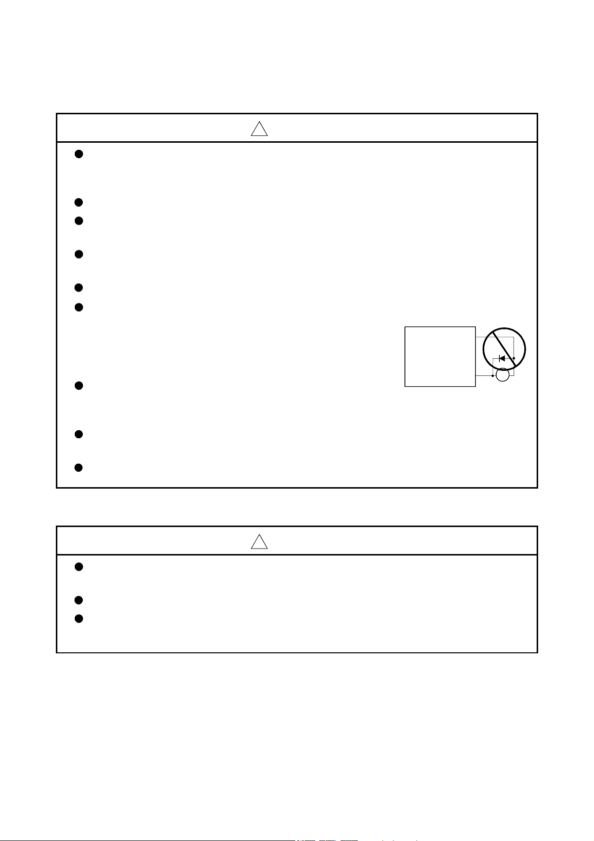
Do not mistake the direction of the surge absorbing diode
installed on the DC relay for the control signal output of
brake signals, etc. Incorrect installation may lead to signals
not being output when trouble occurs or the protective
functions not functioning.
Do not connect or disconnect the connection cables between
each unit, the encoder cable or PLC expansion cable while the
power is ON.
Servo amplifier
VIN
(24VDC)
Control output
signal
RA
Securely tighten the cable connector fixing screws and fixing mechanisms. Insufficient fixing
may lead to the cables combing off during operation.
Do not bundle the power line or cables.
(5) Trial operation and adjustment
!
CAUTION
Confirm and adjust the program and each parameter before operation. Unpredictable
movements may occur depending on the machine.
Extreme adjustments and changes may lead to unstable operation, so never make them.
When using the absolute position system function, on starting up, and when the Motion
controller or absolute value motor has been replaced, always perform a home position return.
A - 7
Page 9
(6) Usge methods
!
CAUTION
Immediately turn OFF the power if smoke, abnormal sounds or odors are emitted from the
Motion controller, servo amplifier or servomotor.
Always execute a test operation before starting actual operations after the program or
parameters have been changed or after maintenance and inspection.
The units must be disassembled and repaired by a qualified technician.
Do not make any modifications to the unit.
Keep the effect or electromagnetic obstacles to a minimum by installing a noise filter or by using
wire shields, etc. Electromagnetic obstacles may affect the electronic devices used near the
Motion controller or servo amplifier.
When using the CE Mark-compliant equipment, refer to the "EMC Installation Guidelines"
(data number IB(NA)-67339) for the Motion controllers and refer to the corresponding EMC
guideline information for the servo amplifiers, inverters and other equipment.
Use the units with the following conditions.
Item
Input power
Input frequency 50/60Hz ±5%
Tolerable
momentary
power failure
Q61P-A1 Q61P-A2 Q62P Q63P Q64P
100 to 120VAC
(85 to 132VAC) (170 to 264VAC) (85 to 264VAC) (15.6 to 31.2VDC)
+10% +10% +10% +30% +10%
200 to 240VAC
-15%
200 to 240VAC
-15%
Conditions
100 to 240VAC
20ms or less
-15%
24VDC
-35%
100 to 120VAC
(7) Corrective actions for errors
!
CAUTION
If an error occurs in the self diagnosis of the Motion controller or servo amplifier, confirm the
check details according to the instruction manual, and restore the operation.
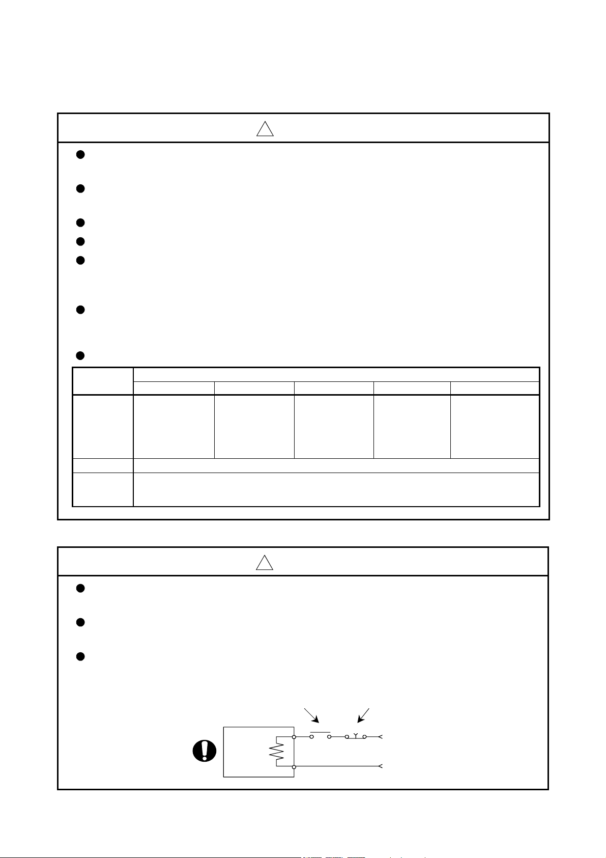
If a dangerous state is predicted in case of a power failure or product failure, use a servomotor
with electromagnetic brakes or install a brake mechanism externally.
Use a double circuit construction so that the electromagnetic brake operation circuit can be
operated by emergency stop signals set externally.
Shut off with servo ON signal OFF,
alarm, magnetic brake signal.
Servomotor
RA1
Shut off with the
emergency stop
signal(EMG).
EMG
-15%
+10%
-15%
(85 to 132VAC/
170 to 264VAC)
/
Electromagnetic
brakes
24VDC
A - 8
Page 10
!
CAUTION
If an error occurs, remove the cause, secure the safety and then resume operation after alarm
release.
The unit may suddenly resume operation after a power failure is restored, so do not go near the
machine. (Design the machine so that personal safety can be ensured even if the machine
restarts suddenly.)
(8) Maintenance, inspection and part replacement
!
CAUTION
Perform the daily and periodic inspections according to the instruction manual.
Perform maintenance and inspection after backing up the program and parameters for the
Motion controller and servo amplifier.
Do not place fingers or hands in the clearance when opening or closing any opening.
Periodically replace consumable parts such as batteries according to the instruction manual.
Do not touch the lead sections such as ICs or the connector contacts.
Do not place the Motion controller or servo amplifier on metal that may cause a power leakage
or wood, plastic or vinyl that may cause static electricity buildup.
Do not perform a megger test (insulation resistance measurement) during inspection.
When replacing the Motion controller or servo amplifier, always set the new module settings
correctly.
When the Motion controller or absolute value motor has been replaced, carry out a home
position return operation using one of the following methods, otherwise position displacement
could occur.
1) After writing the servo data to the Motion controller using programming software, switch on
the power again, then perform a home position return operation.
2) Using the backup function of the programming software, load the data backed up before
replacement.
After maintenance and inspections are completed, confirm that the position detection of the
absolute position detector function is correct.
Do not short circuit, charge, overheat, incinerate or disassemble the batteries.
The electrolytic capacitor will generate gas during a fault, so do not place your face near the
Motion controller or servo amplifier.
The electrolytic capacitor and fan will deteriorate. Periodically replace these to prevent
secondary damage from faults. Replacements can be made by our sales representative.
A - 9
Page 11
(9) About processing of waste
When you discard Motion controller, servo amplifier, a battery (primary battery) and other option articles,
please follow the law of each country (area).
!
CAUTION
This product is not designed or manufactured to be used in equipment or systems in situations
that can affect or endanger human life.
When considering this product for operation in special applications such as machinery or
systems used in passenger transportation, medical, aerospace, atomic power, electric power, or
submarine repeating applications, please contact your nearest Mitsubishi sales representative.
Although this product was manufactured under conditions of strict quality control, you are
strongly advised to install safety devices to forestall serious accidents when it is used in facilities
where a breakdown in the product is likely to cause a serious accident.
(10) General cautions
!
CAUTION
All drawings provided in the instruction manual show the state with the covers and safety
partitions removed to explain detailed sections. When operating the product, always return the
covers and partitions to the designated positions, and operate according to the instruction
manual.
A - 10
Page 12

REVISIONS
The manual number is given on the bottom left of the back cover.
Print Date Manual Number Revision
Mar., 2003 IB(NA)-0300044-A First edition
Jun., 2004 IB(NA)-0300044-B [Addition model]
Q172EX-S1, Q173PX-S1, FR-V5
[Addition function]
For Home position return function
[Additional correction/partial correction]
Safety precautions, About processing of waste, Error code list, etc.
Mar., 2006 IB(NA)-0300044-C [Addition model]
Q62P, Q172EX-S2, Q172EX-S3, Q170ENC
[Addition function]
Cam axis command signal, Smoothing clutch complete signal, Gain
changing signal, Real mode axis information register, Mechanical
system program - Clutch for slippage system (linear
acceleration/deceleration system), Mixed function of virtual mode with
real mode
[Additional correction/partial correction]
Safety precautions, Error code list, Warranty, Manual model code
(1CT783
1XB783), etc.
0-
Japanese Manual Version IB(NA)-0300025
This manual confers no industrial property rights or any rights of any other kind, nor does it confer any patent
licenses. Mitsubishi Electric Corporation cannot be held responsible for any problems involving industrial property
rights which may occur as a result of using the contents noted in this manual.
© 2003 MITSUBISHI ELECTRIC CORPORATION
A - 11
Page 13

INTRODUCTION
Thank you for choosing the Q173CPU(N)/Q172CPU(N) Motion Controller.
Please read this manual carefully so that equipment is used to its optimum.
CONTENTS
Safety Precautions .........................................................................................................................................A- 1
Revisions ........................................................................................................................................................A-11
Contents .........................................................................................................................................................A-12
About Manuals ...............................................................................................................................................A-15
1. OVERVIEW 1- 1 to 1- 4
1.1 Overview................................................................................................................................................... 1- 1
1.2 Motion Control in SV13/SV22 Real Mode ............................................................................................... 1- 3
1.3 Motion Control in SV22 Virtual Mode ......................................................................................................1- 4
2. STARTING UP THE MULTIPLE CPU SYSTEM 2- 1 to 2- 8
2.1 Starting Up the System ............................................................................................................................ 2- 1
2.2 Differences Between Incremental System and Absolute System .......................................................... 2 - 3
2.2.1 Operation for incremental system..................................................................................................... 2 - 3
2.2.2 Operation for absolute (absolute position) system........................................................................... 2 - 4
2.3 Differences Between Real Mode and Virtual Mode ................................................................................ 2 - 5
2.3.1 Positioning data ................................................................................................................................. 2 - 5
2.3.2 Positioning devices............................................................................................................................ 2 - 5
2.3.3 Servo programs................................................................................................................................. 2 - 6
2.3.4 Control change (Current value change/speed change) ................................................................... 2 - 7
3. PERFORMANCE SPECIFICATIONS 3- 1 to 3- 2
4. POSITIONING DEDICATED SIGNALS 4- 1 to 4-88
4.1 Internal Relays ......................................................................................................................................... 4- 2
4.1.1 Axis statuses ..................................................................................................................................... 4-17
4.1.2 Axis command signals ...................................................................................................................... 4-23
4.1.3 Virtual servomotor axis statuses....................................................................................................... 4-27
4.1.4 Virtual servomotor axis command signals ......................................................................................4-32
4.1.5 Synchronous encoder axis statuses ............................................................................................... 4-37
4.1.6 Synchronous encoder axis command signals..................................................................................4-39
4.1.7 Cam axis command signals.............................................................................................................. 4-40
4.1.8 Smoothing clutch complete signals ..................................................................................................4-41
4.1.9 Common devices .............................................................................................................................. 4-43
4.2 Data Registers.......................................................................................................................................... 4-57
4.2.1 Axis monitor devices ......................................................................................................................... 4-65
4.2.2 Control change registers ................................................................................................................... 4-67
4.2.3 Virtual servomotor axis monitor devices........................................................................................... 4-68
A - 12
Page 14

4.2.4 Current value after virtual servomotor axis main shaft's differential gear ....................................... 4-70
4.2.5 Synchronous encoder axis monitor devices..................................................................................... 4-72
4.2.6 Current value after synchronous encoder axis main shaft's differential gear .................................4-73
4.2.7 Cam axis monitor devices .................................................................................................................4-75
4.2.8 Common devices .............................................................................................................................. 4-76
4.3 Motion registers (#) ..................................................................................................................................4-80
4.4 Special relays (SP.M) ..............................................................................................................................4-81
4.5 Special registers (SP.D)........................................................................................................................... 4-83
5. MECHANICAL SYSTEM PROGRAM 5- 1 to 5- 6
5.1 Mechanical Module Connection Diagram ............................................................................................... 5- 2
5.2 Mechanical Module List ........................................................................................................................... 5- 5
6. DRIVE MODULE 6- 1 to 6-24
6.1 Virtual Servomotor ................................................................................................................................... 6- 1
6.1.1 Operation description ........................................................................................................................ 6- 1
6.1.2 Parameter list .................................................................................................................................... 6-11
6.1.3 Virtual servomotor axis devices (Internal relays, data registers)..................................................... 6-15
6.2 Synchronous Encoder.............................................................................................................................. 6-16
6.2.1 Operation description ........................................................................................................................ 6-16
6.2.2 Parameter list .................................................................................................................................... 6-20
6.2.3 Synchronous encoder axis devices (Internal relays, data registers) ............................................... 6-21
6.3 Virtual Servomotor/Synchronous Encoder Control Change................................................................... 6-22
6.3.1 Virtual servomotor control change ....................................................................................................6-22
6.3.2 Synchronous encoder control change.............................................................................................. 6-24
7. TRANSMISSION MODULE 7- 1 to 7-38
7.1 Gear .......................................................................................................................................................... 7- 3
7.1.1 Operation........................................................................................................................................... 7- 3
7.1.2 Parameters ........................................................................................................................................ 7- 3
7.2 Clutch........................................................................................................................................................ 7- 5
7.2.1 Operation........................................................................................................................................... 7-11
7.2.2 Parameters ........................................................................................................................................ 7-28
7.3 Speed Change Gear ................................................................................................................................ 7-34
7.3.1 Operation........................................................................................................................................... 7-34
7.3.2 Parameters ........................................................................................................................................ 7-35
7.4 Differential Gear .......................................................................................................................................7-37
7.4.1 Operation........................................................................................................................................... 7-37
7.4.2 Parameters (Must be not set) ........................................................................................................... 7-37
8. OUTPUT MODULE 8- 1 to 8-38
8.1 Rollers....................................................................................................................................................... 8- 4
8.1.1 Operation........................................................................................................................................... 8- 4
8.1.2 Parameter list .................................................................................................................................... 8- 5
8.2 Ball Screw................................................................................................................................................. 8- 9
8.2.1 Operation........................................................................................................................................... 8- 9
A - 13
Page 15

8.2.2 Parameter list .................................................................................................................................... 8-10
8.3 Rotary Tables ...........................................................................................................................................8-13
8.3.1 Operation........................................................................................................................................... 8-13
8.3.2 Parameter list .................................................................................................................................... 8-14
8.4 Cam .......................................................................................................................................................... 8-21
8.4.1 Operation........................................................................................................................................... 8-22
8.4.2 Settings items at cam data creating ................................................................................................. 8-25
8.4.3 Parameter list .................................................................................................................................... 8-29
8.4.4 Cam curve list.................................................................................................................................... 8-37
9. REAL/VIRTUAL MODE SWITCHING AND STOP/RE-START 9- 1 to 9-12
9.1 Switching from the Real to Virtual Mode .................................................................................................9- 1
9.2 Switching from the Virtual to Real Mode .................................................................................................9- 5
9.2.1 Switching from the virtual to real mode by user side ....................................................................... 9- 5
9.2.2 Switching from the virtual to real mode by operating system software ........................................... 9- 5
9.2.3 Continuous operation on servo error in virtual mode .......................................................................9- 6
9.3 Precautions at Real/Virtual Mode Switching ........................................................................................... 9- 7
9.4 Stop and re-start....................................................................................................................................... 9- 9
9.4.1 Stop operation/stop causes during operation and re-starting operation list.................................... 9-10
10. AUXILIARY AND APPLIED FUNCTIONS 10- 1 to 10- 8
10.1 Mixed Function of Virtual Mode with Real Mode ................................................................................ 10- 1
10.2 Cam/Ball Screw Switching Function.................................................................................................... 10- 7
APPENDICES APP- 1 to APP-75
APPENDIX 1 Cam Curves........................................................................................................................APP- 1
APPENDIX 2 Error Codes Stored Using The Motion CPU ...................................................................APP- 5
APPENDIX 2.1 Expression Method for Word Data Axis No. ............................................................... APP- 8
APPENDIX 2.2 Related Systems and Error Processing......................................................................APP- 9
APPENDIX 2.3 Servo program setting errors (Stored in D9190) ........................................................APP-10
APPENDIX 2.4 Drive module errors.....................................................................................................APP-15
APPENDIX 2.5 Servo errors.................................................................................................................APP-20
APPENDIX 2.6 PC link communication errors .....................................................................................APP-36
APPENDIX 2.7 Output Module Errors ..................................................................................................APP-37
APPENDIX 2.8 Errors at Real/Virtual Mode Switching ........................................................................APP-43
APPENDIX 3 Special Relays/special registers ........................................................................................APP-45
APPENDIX 3.1 Special relays ..............................................................................................................APP-45
APPENDIX 3.2 Special registers ..........................................................................................................APP-49
APPENDIX 4 Setting Range for Indirect Setting Devices........................................................................APP-53
APPENDIX 5 Processing Times of the Motion CPU ...............................................................................APP-55
A - 14
Page 16

About Manuals
This manual is only to explain hardware of the Motion controller.
The following manuals are related to this product.
Referring to this list, please request the necessary manuals.
This User's Manual do not describes hardware specification and handling methods of the PLC CPU
modules, power supply modules, base unit and I/O module in details.
The above contents, refer to the QCPU User's Manual and Building Block I/O Module User's Manual.
Related Manuals
(1) Motion controller
Q173CPU(N)/Q172CPU(N) Motion controller User's Manual
This manual explains specifications of the Motion CPU modules, Q172LX Servo external signal interface
module, Q172EX Serial absolute synchronous encoder interface module, Q173PX Manual pulse
generator interface module, Teaching units, Power supply modules, Servo amplifiers, SSCNET cables,
synchronous encoder cables and others.
(Optional)
Q173CPU(N)/Q172CPU(N) Motion controller (SV13/SV22) Programming Manual
(Motion SFC)
This manual explains the Multiple CPU system configuration, performance specifications, functions,
programming, error codes and others of the Motion SFC.
(Optional)
Manual Name
Manual Number
(Model Code)
IB-0300040
(1XB780)
IB-0300042
(1XB781)
Q173CPU(N)/Q172CPU(N) Motion controller (SV13/SV22) Programming Manual
(REAL MODE)
This manual explains the servo parameters, positioning instructions, device list, error list and others.
(Optional)
Q173CPU(N)/Q172CPU(N) Motion controller (SV43) Programming Manual
This manual describes the dedicated instructions to execute the positioning control by Motion program of
EIA language (G-code).
This manual explains the Multiple CPU system configuration, performance specifications, functions,
programming, debugging, servo parameters, positioning instructions device list and error list and others.
(Optional)
IB-0300043
(1XB782)
IB-0300070
(1CT784)
A - 15
Page 17

(2) PLC
QCPU User's Manual (Hardware Design, Maintenance and Inspection)
This manual explains the specifications of the QCPU modules, power supply modules, base modules,
extension cables, memory card battery and others.
(Optional)
QCPU User's Manual (Function Explanation, Program Fundamentals)
This manual explains the functions, programming methods and devices and others to create programs
with the QCPU.
(Optional)
QCPU User's Manual (Multiple CPU System)
This manual explains the functions, programming methods and cautions and others to construct the
Multiple CPU system with the QCPU.
(Optional)
QCPU (Q Mode)/QnACPU Programming Manual (Common Instructions)
This manual explains how to use the sequence instructions, basic instructions, application instructions and
micro computer program.
(Optional)
QCPU (Q Mode)/QnACPU Programming Manual (PID Control Instructions)
This manual explains the dedicated instructions used to exercise PID control.
(Optional)
QCPU (Q Mode)/QnACPU Programming Manual (SFC)
This manual explains the system configuration, performance specifications, functions, programming,
debugging, error codes and others of MELSAP3.
(Optional)
I/O Module Type Building Block User's Manual
This manual explains the specifications of the I/O modules, connector, connector/terminal block
conversion modules and others.
(Optional)
Manual Name
Manual Number
(Model Code)
SH-080483ENG
(13JR73)
SH-080484ENG
(13JR74)
SH-080485ENG
(13JR75)
SH-080039
(13JF58)
SH-080040
(13JF59)
SH-080041
(13JF60)
SH-080042
(13JL99)
A - 16
Page 18
1 OVERVIEW
1. OVERVIEW
1.1 Overview
This programming manual describes the dedicated instructions, positioning control
parameters and positioning dedicated devices for mechanical system program
comprised of a virtual main shaft or mechanical module required to execute the
synchronous control in the Motion controller (SV22 virtual mode).
The following positioning control is possible in the Motion controller (SV22 virtual
Generic term/abbreviation Description
Q173CPU(N)/Q172CPU(N),
Motion CPU or Motion CPU module
Q172LX/Q172EX/Q173PX
or Motion module
MR-H-BN Servo amplifier model MR-H BN
MR-J2 -B Servo amplifier model MR-J2S- B/MR-J2M-B/MR-J2- B/MR-J2-03B5
AMP or Servo amplifier
QCPU, PLC CPU
or PLC CPU module
Multiple CPU system
or Motion system
CPUn
Programming software package General name for "MT Developer" and "GX Developer"
Operating system software General name for "SW RN-SV Q "
SV13
SV22
MT Developer Abbreviation for Integrated start-up support software package "MT Developer"
GX Developer
Manual pulse generator
or MR-HDP01
Serial absolute synchronous encoder
or MR-HENC/Q170ENC
SSCNET
(Note-2)
mode).
Applicable CPU Number of positioning control axes
Q173CPU(N) (32 axes) Up to 32 axes
Q172CPU(N) (8 axes) Up to 8 axes
In this manual, the following abbreviations are used.
Q173CPUN/Q172CPUN/Q173CPUN-T/Q172CPUN-T/Q173CPU/Q172CPU
Motion CPU module
Q172LX Servo external signals interface module/
Q172EX(-S1/-S2/-S3) Serial absolute synchronous encoder interface module
Q173PX(-S1) Manual pulse generator interface module
General name for "Servo amplifier model MR-H
MR-J2-
Qn(H)CPU
Abbreviation for "Multiple PLC system of the Q series"
Abbreviation for "CPU No.n (n= 1 to 4) of the CPU module for the Multiple CPU
system"
Operating system software for conveyor assembly use (Motion SFC) :
SW6RN-SV13Q
Operating system software for automatic machinery use (Motion SFC) :
SW6RN-SV22Q
Abbreviation for MELSEC PLC programming software package "GX Developer
(Version 6 or later)"
Abbreviation for "Manual pulse generator (MR-HDP01)"
Abbreviation for "Serial absolute synchronous encoder (MR-HENC/Q170ENC)"
High speed serial communication between Motion controller and servo amplifier
B/MR-J2-03B5, Vector inverter FREQROL-V500 series"
BN/MR-J2S- B/MR-J2M-B/
(Note-1)
1
/
1 - 1
Page 19
1 OVERVIEW
Generic term/abbreviation Description
Absolute position system
Cooling fan unit Cooling fan unit (Q170FAN)
Dividing unit Dividing unit (Q173DV)
Battery unit Battery unit (Q170BAT)
A 0BD-PCF A10BD-PCF/A30BD-PCF SSC I/F board
SSC I/F communication cable Abbreviation for "Cable for SSC I/F board/card"
Intelligent function module
Vector inverter (FR-V500) Vector inverter FREQROL-V500 series
General name for "System using the servomotor and servo amplifier for
absolute position"
Abbreviation for "MELSECNET/H module/Ethernet module/CC-Link
module/Serial communication module"
(Note-1) : Q172EX can be used in SV22.
(Note-2) : SSCNET: S
REMARK
ervo System Controller NETwork
For information about the each module, design method for program and parameter,
Motion CPU module/Motion unit Q173CPU(N)/Q172CPU(N) User’s Manual
PLC CPU, peripheral devices for PLC program design, I/O
modules and intelligent function module
Operation method for MT Developer Help of each software
• Multiple CPU system configuration
• Performance specification
• Design method for common parameter
SV13/SV22
• Auxiliary and applied functions
• Design method for positioning control program in
the real mode
• Design method for positioning control parameter
refer to the following manuals relevant to each module.
Item Reference Manual
Manual relevant to each module
Q173CPU(N)/Q172CPU(N) Motion controller
(SV13/SV22) Programming Manual (Motion SFC)
Q173CPU(N)/Q172CPU(N) Motion controller
(SV13/SV22) Programming Manual (REAL MODE)
!
CAUTION
When designing the system, provide external protective and safety circuits to ensure safety in
the event of trouble with the Motion controller.
There are electronic components which are susceptible to the effects of static electricity
mounted on the printed circuit board. When handling printed circuit boards with bare hands you
must ground your body or the work bench.
Do not touch current-carrying or electric parts of the equipment with bare hands.
Make parameter settings within the ranges stated in this manual.
Use the program instructions that are used in programs in accordance with the conditions
stipulated in this manual.
Some devices for use in programs have fixed applications: they must be used in accordance
with the conditions stipulated in this manual.
1 - 2
Page 20

1 OVERVIEW
1.2 Motion Control in SV13/SV22 Real Mode
(1) System with servomotor is controlled directly using the servo program in
(SV13/SV22) real mode.
(2) Setting of the positioning parameter and creation of the servo program/Motion
SFC program are required.
(3) The procedure of positioning control is shown below:
1) Motion SFC program is requested to start using the S(P). SFCS instruction of
the PLC program.
(Motion SFC program can also be started automatically by parameter setting.)
2) Execute the positioning control using the specified Motion SFC program.
(Output to the servo amplifier)
3) The servomotor is controlled.
Program structure in SV13/SV22 real mode
<PLC CPU>
PLC program
SP.SFCS
Motion SFC
program start
request instruction
(Note) : Motion SFC program can also be started automatically
by parameter setting.
K0
••••
•••• ••••
Specification of starting
program No.
<Motion CPU>
Motion SFC program
1)
[G100]
M2049//servo ON accept ?
Servo program
[K10: real]
1 INC-2
Axis 1, 10000 PLS
Axis 2, 20000 PLS
Combined-speed 30000 PLS/s
Positioning control parameters
System settings
Fixed parameters
Servo parameters
Parameter blocks
Home position return data
JOG operation data
Limit switch output data
Transfer
END
2)
3)
Servo amplifier
Servomotor
1 - 3
Page 21
1 OVERVIEW
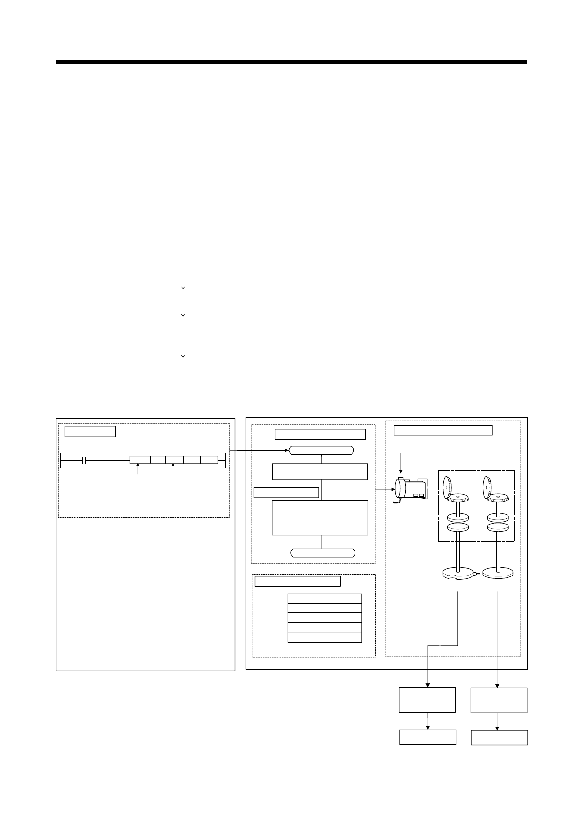
1.3 Motion Control in SV22 Virtual Mode
(1) Synchronous control with software is performed using the mechanical system
program comprised by virtual main shaft and mechanical module in (SV22) virtual
mode.
(2) Mechanical system programs is required in addition to the positioning parameter,
servo program/Motion SFC program used in real mode.
(3) The procedure of positioning control in virtual model is shown below:
1) Motion SFC program for virtual mode is requested to start using the S(P).
SFCS instruction of the PLC program.
(Motion SFC program can also be started automatically by parameter setting.)
2) The virtual servomotor of the mechanical system program is started.
3) Output the operation result obtained through the transmission module to the
servo amplifier set as the output module.
4) The servomotor is controlled.
Program structure in SV22 virtual mode
<PLC CPU>
PLC program
SP.SFCS
Motion SFC
program star t
request inst ruction
(Note) : Motion SFC program can also be started automatically
by parameter setting.
• Home position return data is not used, since home position return cannot be executed in virtual mode.
(Home position return is executed in real mode.)
• JOG operation in virtual mode is controlled using the JOG operation data set by drive module parameters.
K0
••••
•••• ••••
Specification of starting
program No.
<Motion CPU>
Motion SFC program
1)
[G200]
M2044//on virtual mode?
Servo program
[K100: virtual]
1 VF
Axis 1,
Speed # 0 PLS/s
Positioning control parameters
Transfer
END
System settings
Fixed parameters
Servo parameters
Parameter blocks
Limit switch output data
Mechanical system program
Drive module
(Virtual servomotor)
Transmission module
2)
(Axis 1)
Output module
3)
Servo amplifier
3)
Servo amplifier
4)
Servomotor
4)
Servomotor
1 - 4
Page 22
2 STARTING UP THE MULTIPLE CPU SYSTEM
2. STARTING UP THE MULTIPLE CPU SYSTEM
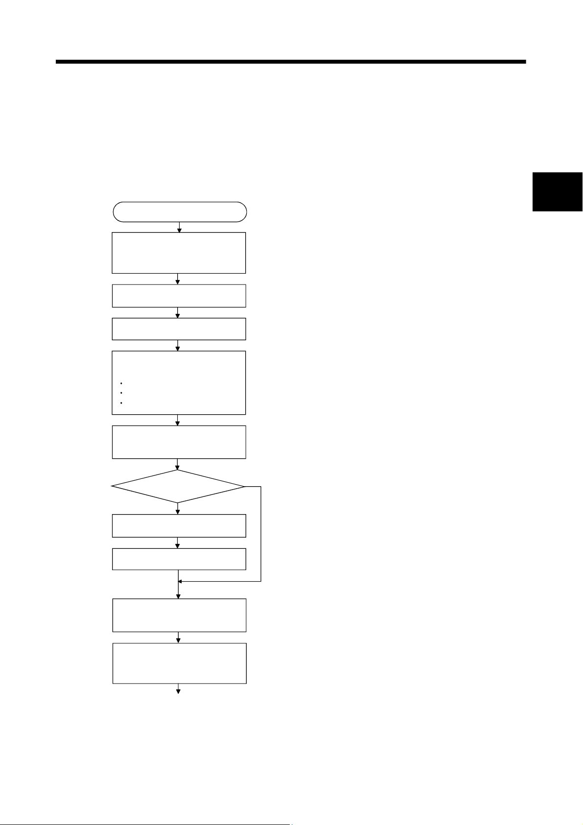
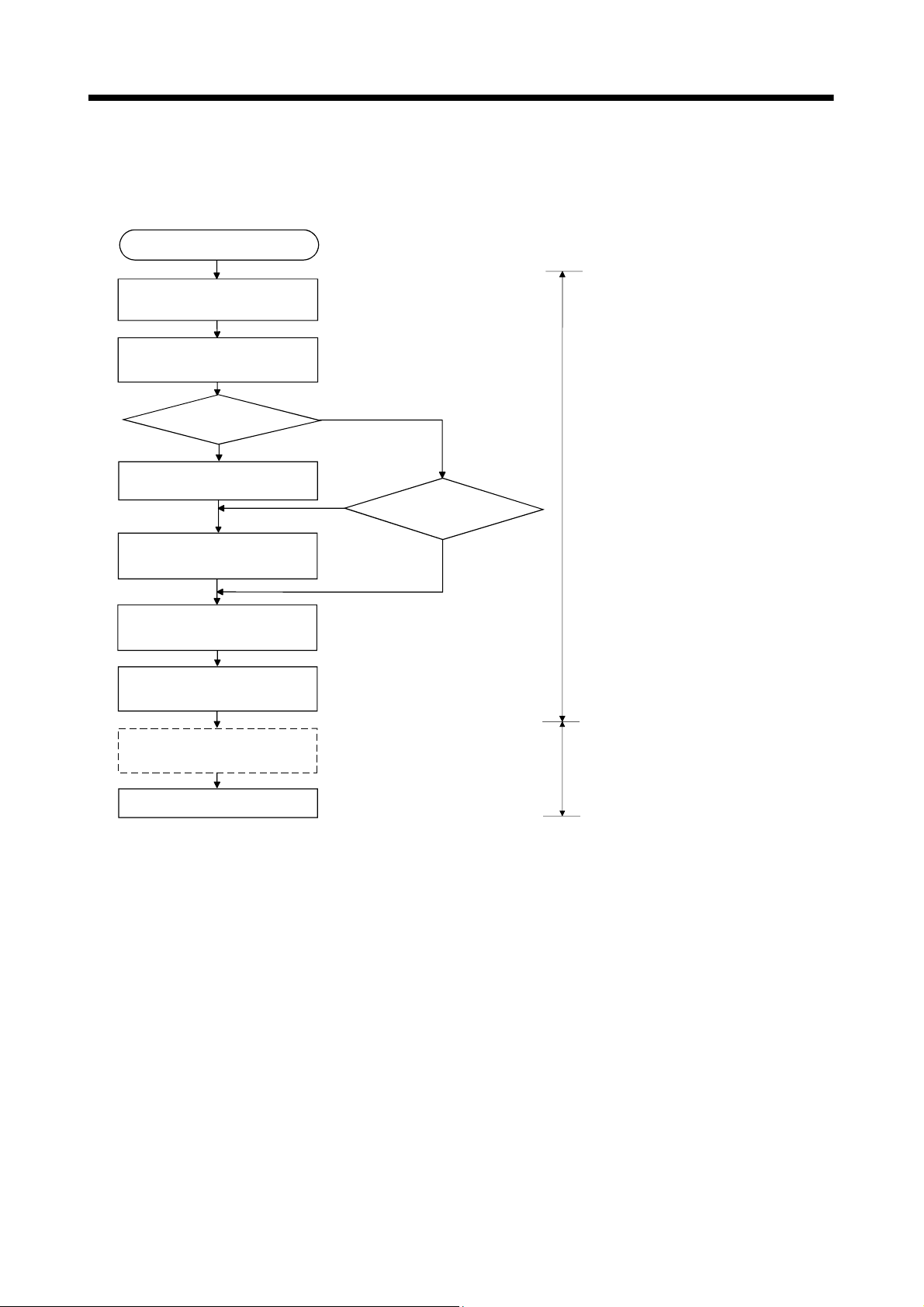
The procedure for virtual mode positioning control is shown below.
2.1 Starting Up the System
Install SW6RN-GSV22P,
SW3RN-CAMP(When cam is
used)
Starting up SW6RN-GSV22P
System settings
Set the following positioning
parameters
Fixed parameters
Servo parameters
Parameter blocks
The procedure to start up for virtual mode system is shown below.
START
2
Refer to Section "1.5 System Settings" of the
Q173CPU(N)/Q172CPU(N) Motion controller
(SV13/SV22) Programming Manual (Motion SFC).
Refer to Chapter "4 PARAMETERS FOR POSITIONING
CONTROL" of the Q173CPU(N)/Q172CPU(N) Motion
controller (SV13/SV22) Programming Manual (REAL MODE).
Execute the relative check, and
correct the setting errors
Will cam be used ?
YES
Starting up SW3RN-CAMP
Cam data settings
Create the mechanical system
program
Check the mechanical system
program, and correct the setting
errors
1)
NO
Refer to Section "1.5 System Settings" of the
Q173CPU(N)/Q172CPU(N) Motion controller
(SV13/SV22) Programming Manual (Motion SFC).
2 - 1
Page 23
2 STARTING UP THE MULTIPLE CPU SYSTEM
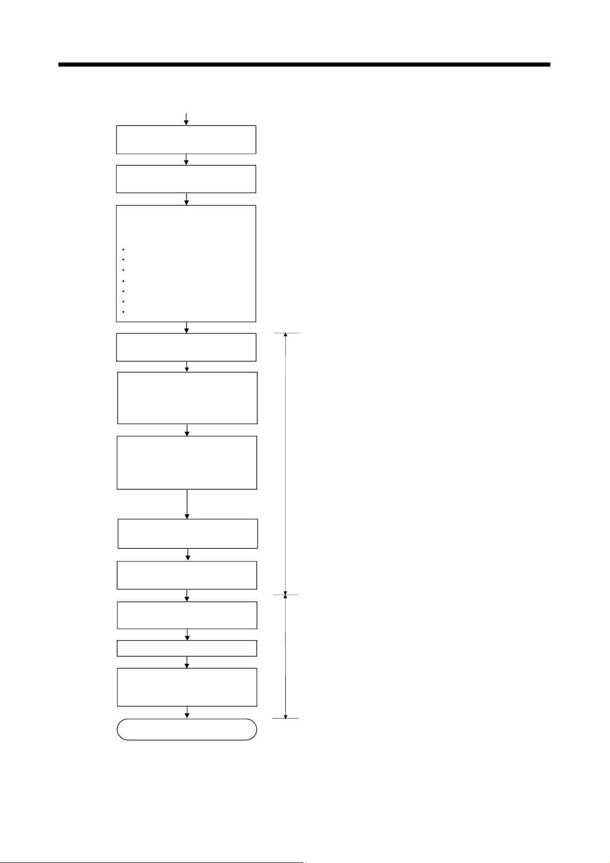
1)
Create the Motion SFC program
and servo program
Turn the power supply of
Multiple CPU system ON
Write the following data to the
Motion CPU using a peripheral
device
System setting data
Servo setting data
Motion SFC parameter
Motion SFC program
Servo program
Mechanical system program
Cam data(When cam is used)
Starting up the servo amplifier
using a peripheral device
Execute the JOG operation,
manual pulse generator
operation and home position
return test
Adjust cam setting axis (When
cam is used)
(Bottom dead point, stroke value,
etc.)
Align the virtual mode operation
start position
Set data in the parameter
setting device
Switch from real mode to virtual
mode
Refer to Section "1.5 System Settings" of the
Q173CPU(N)/Q172CPU(N) Motion controller
(SV13/SV22) Programming Manual (Motion SFC).
Real mode
Start drive module operation
Check operation state with the
servo monitor or mechanical
system monitor
END
Virtual mode
2 - 2
Page 24
2 STARTING UP THE MULTIPLE CPU SYSTEM
2.2 Differences Between Incremental System and Absolute System
The procedure for virtual mode operation is shown below.
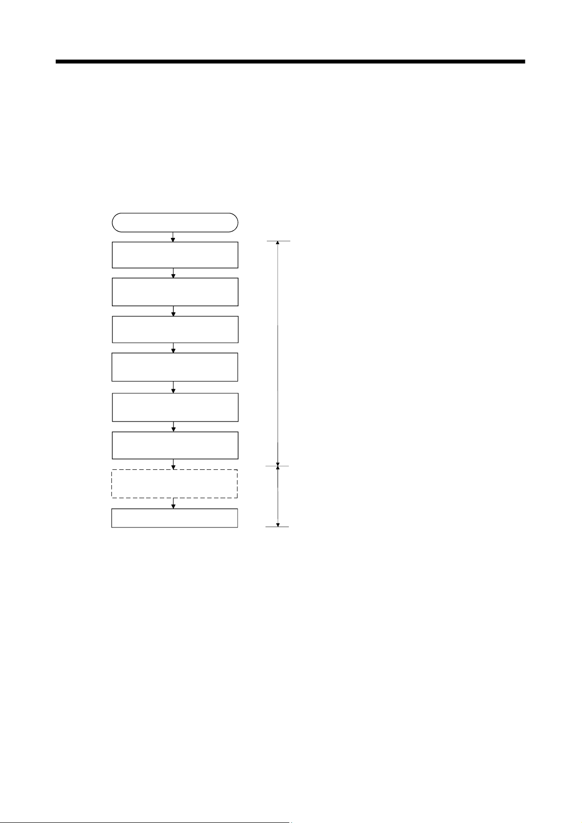
2.2.1 Operation for incremental system
The operation procedure for incremental system is shown below.
START
Turn the power supply of
Multiple CPU system ON
Execute the all axes servo
start request (Turn M2042 on)
Execute the home position
return
Align the virtual mode
operation start position
Set data in the parameter
setting device
Switch from real mode to
virtual mode
Set the operation start address
by the current value change
Refer to Section "1.5 System Settings" of the
Q173CPU(N)/Q172CPU(N) Motion controller
(SV13/SV22) Programming Manual (Motion SFC).
Real mode
Virtual mode
Execute virtual mode operation
2 - 3
Page 25
2 STARTING UP THE MULTIPLE CPU SYSTEM
2.2.2 Operation for absolute (absolute position) system
START
Turn the power supply of
Multiple CPU system ON
Execute the all axes servo
start request (Turn M2042 on)
Is the home
position return request
signal ON ?
Execute the home position
return
Align the virtual mode
operation start position
Set data in the parameter
setting device
The operation procedure for absolute system is shown below.
Refer to Section "1.5 System Settings"
of the Q173CPU(N)/Q172CPU(N) Motion
controller (SV13/SV22) Programming
Manual (Motion SFC).
NO
YES
NO
Is the continuation disabled warning
signal ON ?
YES
Real mode
Switch from real mode to
virtual mode
Set the operation start address
by the current value change
Execute virtual mode operation
Virtual mode
2 - 4
Page 26
2 STARTING UP THE MULTIPLE CPU SYSTEM
2.3 Differences Between Real Mode and Virtual Mode
Specifications of the positioning data, positioning devices and servo programs, etc.
used in the real mode differ in part in the virtual mode.
When using them in the virtual mode, refer to the "Q173CPU(N)/Q172CPU(N) Motion
controller (SV13/SV22) Programming Manual (REAL MODE)" after checking about a
different point in the real mode.
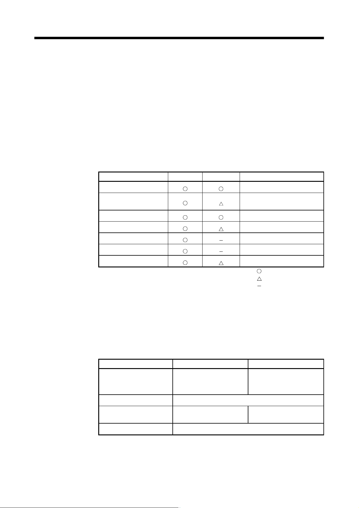
2.3.1 Positioning data
Positioning data used in the virtual mode are shown in Table 2.1 below.
Table 2.1 Positioning Data List
Item Real mode Virtual mode Remark
System settings
Fixed parameters
Servo parameters
Parameter blocks
Home position return data
JOG operation data
Limit switch output data
2.3.2 Positioning devices
The operating ranges of positioning devices used in virtual mode are shown in Table
2.2 below.
Usable units differ according to
the output module.
Only [PLS] usable.
: Used
: Used (Restrictions in part)
: Not used
Table 2.2 Operating Range of Positioning Devices
Device name Real mode Virtual mode
M2000 to M3839
Internal relays
Special relays M9073 to M9079
Data registers
Special registers D9180 to D9201
M4640 to M4687
M5440 to M5487
D0 to D799
D1120 to D1239
M2000 to M5599
D0 to D1559
2 - 5
Page 27
2 STARTING UP THE MULTIPLE CPU SYSTEM
2.3.3 Servo programs
(1) Servo program area
(a) The same servo program (Kn) No. cannot be used in both the real and virtual
modes. The range of the servo program (Kn) used in the virtual mode must
be set in advance.
(The range is set using a peripheral device which started SW6RN-GSV22P.)
(2) Servo instructions
(a) The home position return, speed control (
and high-speed oscillation control among the controls which can be used in
the real mode cannot be used in the virtual mode.
(b) Control units of the parameter block and the torque limit value among the
positioning data which can be set using the servo program are not used.
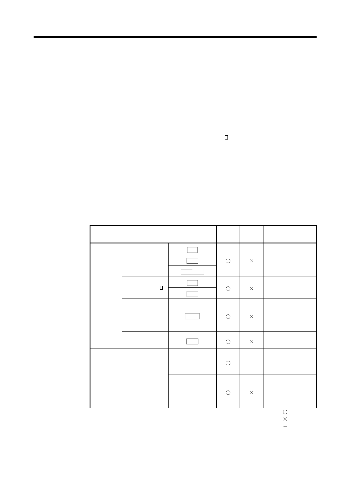
(3) Differences of the servo instruction between real mode and virtual mode are
shown in Table 2.3 below.
Table 2.3 Differences of Servo Instruction List
), speed/position switching control
Item
VPF
Speed/position
control
Servo
instruction
Positioning
data
(Note) : It is common in the real mode and virtual mode about instructions except for the above
Speed control ( )
Home position
return
High-speed
oscillation
Control units
Parameter block
Torque limit value
table.
VPR
VPSTART
ZERO
VVF
VVR
OSC
Real
mode
Virtual
mode
Fixed
as
"PLS"
Remark
Switch to virtual
mode after home
position return in the
real mode.
The torque limit
value is set with the
"drive module
parameter".
: Used
: Unusable
: Not used
2 - 6
Page 28
2 STARTING UP THE MULTIPLE CPU SYSTEM
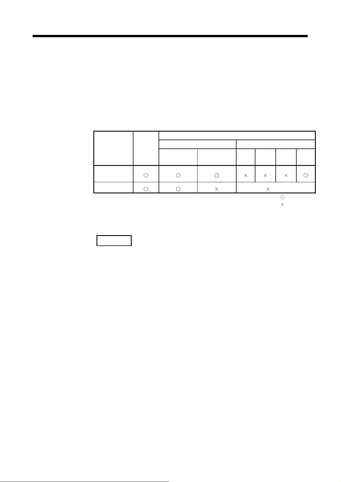
2.3.4 Control change (Current value change/speed change)
When a control change is executed in the virtual mode, the feed current value/speed of
the drive module is changed.
Control changes are not possible for the output module (except for cam).
Differences between control changes in the real and virtual modes are shown in Table
2.4 below.
Table 2.4 Differences List of Control Change
Item
Current value
change
Speed change
(Note-1) : If the output module is a roller which uses a speed change gear, a speed change can
be executed by changing the speed change gear ratio.
Real
mode
Drive module Output module
Virtual
servomotor
Synchronous
encoder
Virtual mode
Roller
Ball
screw
Rotary
(Note-1)
table
: Used
: Unusable
Cam
REMARK
1) Refer to the following Chapters for details of the drive and output modules.
• Drive module : Chapter 5 and 6
• Output module : Chapter 5 and 8
2 - 7
Page 29

2 STARTING UP THE MULTIPLE CPU SYSTEM
MEMO
2 - 8
Page 30
3 PERFORMANCE SPECIFICATIONS
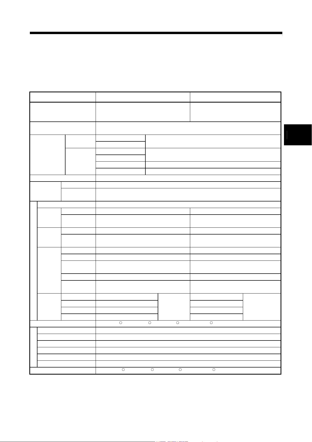
3. PERFORMANCE SPECIFICATIONS
Performance specifications of the Motion CPU are shown in Table 3.1 below.
Table 3.1 Motion CPU Performance Specifications (Virtual Mode)
Item Q173CPUN(-T)/Q173CPU Q172CPUN(-T)/Q172CPU
Up to 32 axes
Number of control axes
Control method
Drive module
Control units
Program language Dedicated instructions (Servo program + mechanical system program)
Servo program
Number of modules which can be set per CPU
Drive
modules
Virtual
axes
Transmis-
sion
modules
Mechanical system program
Output
modules
Program setting method WindowsNTR4.0/ WindowsR98/ WindowsR2000/ Windows RXP which started SW6RN-GSV22P
Types
Resolution per cycle
Memory capacity 132k bytes
Storage memory for cam data CPU internal RAM memory
Cam
Stroke resolution 32767
Control mode Two-way cam/feed cam
Cam data setting method WindowsNTR4.0/ WindowsR98/ WindowsR2000/ Windows RXP which started SW3RN-CAMP
Output module
Capacity
Number of
positioning points
Virtual module 32 axes 8 axes
Synchronous
encoder
Main shaft 32 8
Auxiliary input
axis
Gear 64 16
Clutch 64 16
Speed change
gear
Differential gear 32 8
Differential gear
to main shaft
Roller 32 8
Ball screw 32 8
Rotary table 32 8
Cam 32
Synchronous control, PTP (Point to Point), speed control, fixed-pitch feed, constant-speed control,
Virtual servomotor
Synchronous encoder
Roller
Ball screw
Rotary table Fixed as "degree"
Cam mm, inch, PLS
(Simultaneous : 2 to 4 axes)
(Independent : 32 axes)
position follow-up control, speed-switching control
mm, inch
(Note-3)
(Note-2)
(Note-3)
14k steps (14334 steps)
Total of 3200 points (It changes with programs, indirect specification is possible.)
12 axes 8 axes
32 8
64 16
32 8
Total of 32
Up to 256
256 • 512 • 1024 • 2048
Up to 8 axes
(Simultaneous : 2 to 4 axes)
(Independent : 8 axes)
PLS
Total of 8
8
3
3 - 1
Page 31

r
3 PERFORMANCE SPECIFICATIONS
Table 3.1 Motion CPU Performance Specifications (Virtual Mode) (Continued)
Item Q173CPUN(-T)/Q173CPU Q172CPUN(-T)/Q172CPU
Interpolation functions Linear interpolation (2 to 4 axes), circular interpolation (2 axes)
Control methods
Method
Positioning
Position command Address setting range : –2147483648 to 2147483647 [PLS]
Acceleration/
deceleration
Virtual servomoto
control
JOG operation function Provided
M-function (with mode) M-code output function provided, M-code complete wait function provided
Manual pulse generator operation
function
(Test mode only)
Speed command Speed setting range : 1 to 10000000 [PLS/s]
Automatic
trapezoidal
acceleration/
deceleration
S-curve
acceleration/
deceleration
(Note-1) : When the TREN input signal is used as "external input mode clutch", the high speed reading function cannot be used.
(Note-2) : Capacity matching the servo program for real mode.
(Note-3) : Relation between a resolution per cycle of cam and type are shown below.
Resolution per cycle 256 512 1024 2048
Type 256 128 64 32
(Note-4) : The setting range of 1 to 100 is valid in the SW6RN-SV22Q (Ver. 00B or before).
PTP (Point to Point), speed control, fixed-pitch feed, constant-speed control,
position follow-up control
PTP : Selection of absolute or incremental data method
Fixed-pitch feed : Incremental data method
Constant-speed control : Both absolute and incremental data method can be used together
Position follow-up control : Absolute data method
Acceleration-fixed acceleration/deceleration Time-fixed acceleration/deceleration
Acceleration time : 1 to 65535 [ms]
Deceleration time : 1 to 65535 [ms]
S-curve ratio : 0 to 100[%]
Up to 3 units can be connected.
Up to 3 axes can be operated simultaneously.
Setting of magnification : 1 to 10000
Setting of smoothing magnification provided.
Acceleration/deceleration time:1 to 5000 [ms]
(Only constant-speed control is possible.)
(Note-4)
3 - 2
Page 32

r
4 POSITIONING DEDICATED SIGNALS
4. POSITIONING DEDICATED SIGNALS
The internal signals of the Motion CPU and the external signals to the Motion CPU are
used as positioning signals.
(1) Internal signals
The following five devices of the Motion CPU are used as the internal signals of
the Motion CPU.
• Internal relay (M) .............................. M2000 to M5599 (3600 points)
• Special relay (SP.M) ........................ M9073 to M9079 (7 points)
• Data register (D) .............................. D0 to D1599 (1600 points)
• Motion register (#) ........................... #8000 to #8191 (192 points)
• Special register (SP.D) .................... D9180 to D9201 (22 points)
(2) External signals
The external input signals to the Motion CPU are shown below.
• Upper/lower limit switch input.......... The upper/lower limit of the positioning
range is controlled.
• Stop signal ....................................... Stop signal for speed control.
• Proximity dog signal......................... ON/OFF signal from the proximity dog.
• Speed/position switching signal ...... Signal for switching from speed to position.
• Manual pulse generator input .......... Signal from the manual pulse generator.
Configuration between modules
Motion CPU
2)
Motion control
processor
SSCNET
Servo amplifie
PLC control
processor
PLC CPU
Device memory
Shared CPU
memory
1)
PLC bus
Device memory
Shared CPU
memory
4
Sensor, solenoid, etc.
(DI/O)
PLC intelligent function
module (A/D, D/A, etc.)
Motion control dedicated I/F
(DOG signal, manual
pulse generator)
M
M
Note) : Device memory data : 1) = 2)
Servomotor
Fig.4.1 Flow of the internal signals/external signals
4 - 1
Page 33

4 POSITIONING DEDICATED SIGNALS
The positioning dedicated devices are shown below.
It indicates the device refresh cycle of the Motion CPU for status signal with the
positioning control, and the device fetch cycle of the Motion CPU for command signal
with the positioning control.
The operation cycle and main cycle of the Motion CPU are shown below.
(a) Operation cycle
Item
Number of control axes Up to 32 axes Up to 8 axes
Operation cycle
(Default)
SV22
(b) Main cycle is not fixed-cycle as operation cycle. The cycle is dozens[ms] to
hundreds[ms].
4.1 Internal Relays
Q173CPU(N)
0.88[ms] / 1 to 4 axes
1.77[ms] / 5 to 12 axes
3.55[ms] / 13 to 24 axes
7.11[ms] / 25 to 32 axes
Q172CPU(N)
0.88[ms] / 1 to 4 axes
1.77[ms] / 5 to 8 axes
Device No. Purpose Real Virtual Device No. Purpose Real Virtual
M0 M0
to
M2000 M2000
to
to
M2400 M2400
to
M3040 M2560
to
M3072 M3072
to
M3136 M3136
to
M3200 M3200
to
M3840 M3360
to
User device
(2000 points)
Common device
(320 points)
Special relay allocated device
(Status)
(80 points)
Axis status
(20 points
Real mode …... Each axis
Virtual mode … Output module
Unusable
Common device
(Command signal)
(64 points)
Special relay allocated device
(Command signal)
(64 points)
Axis command signal
(20 points
Real mode …... Each axis
Virtual mode … Output module
Unusable
(1) Internal relay list
Q173CPU(N) Q172CPU(N)
32 axes)
32 axes)
to
to
M2320 M2320
to
to
to
to
to
to
to
User device
(2000 points)
Common device
(320 points)
Special relay allocated device
(Status)
(80 points)
Axis status
(20 points
Real mode …... Each axis
Virtual mode … Output module
Unusable
Common device
(Command signal)
(64 points)
Special relay allocated device
(Command signal)
(64 points)
Axis command signal
(20 points
Real mode …... Each axis
Virtual mode … Output module
Unusable
8 axes)
axes)
8
Real/
virtual
community
4 - 2
Page 34

4 POSITIONING DEDICATED SIGNALS
Internal relay list (Continued)
Q173CPU(N) Q172CPU(N)
Device No. Purpose Real Virtual Device No. Purpose Real Virtual
(Note-1)
M4000
to
M4640
1)
to
M4688
to
M4800
to
M5440
to
M5488
to
M5520
to
M5584
to
M5600 M5600
to to
M8191
M4000
Virtual servomotor axis status
(20 points
(Note-
Synchronous encoder axis
status
(4 points
(Note-1)
M4672
Unusable
(Note-1)
Virtual servomotor axis
command signal
(20 points
(Note-1)
M5440
Synchronous encoder axis
command signal
(4 points
(Note-1)
M5488
Cam axis command signal
(1 point
Smoothing clutch complete
signal
(2 points
Unusable
User device
(2592 points)
32 axes)
12 axes)
32 axes)
12 axes)
32 axes)
32 axes)
(Note-2)
(Note-2)
(Note-3)
Back
up
POINT
• Total number of user device points
4592 points
(Note-1) : Do not set M4000 to M5599 as the latch range in virtual mode.
(Note-2) : "Virtual servomotor axis status/command signal" occupy only the area of
the axis set in the mechanical system program. The unused axis areas in
the mechanical system program can be used as an user device.
(Note-3) : Unused axis of cam axis command signal can be used as an user device.
(Note-4) : As for "axis status (M2400 to)" and "axis command signal (M3200 to)",
only details for internal relays used in the virtual mode are described in
this manual. If it is required, refer to the "Q173CPU(N)/Q172CPU(N)
Motion controller (SV13/SV22) Programming Manual (REAL MODE)".
to
M4160
to
M4640
to
to
M4800
to
M4960
to
to
M5472
to
to
M5496
to
M5520
to
M5536
to
M8191
(Note-1)
Virtual servomotor axis status
(20 points
(Note-1)
Unusable
(Note-1)
Synchronous encoder axis
status
(4 points
(Note-1)
Unusable
(Note-1)
Virtual servomotor axis
command signal
(20 points
(Note-1)
Unusable
(Note-1)
Synchronous encoder axis
command signal
(4 points
(Note-1)
Unusable
(Note-1)
Cam axis command signal
(1 point
Unusable
Smoothing clutch complete
signal
(2 points
Unusable
User device
(2592 points)
8 axes)
8 axes)
8 axes)
8 axes)
8 axes)
8 axes)
(Note-2)
(Note-2)
(Note-3)
It can be used as an user device.
Back
up
: Valid, : Invalid
Virtual
4 - 3
Page 35

4 POSITIONING DEDICATED SIGNALS
Axis No. Device No. Signal name
1 M2400 to M2419
2 M2420 to M2439 Virtual
3 M2440 to M2459
4 M2460 to M2479
5 M2480 to M2499
6 M2500 to M2519 0 Positioning start complete
7 M2520 to M2539 1 Positioning complete
8 M2540 to M2559
9 M2560 to M2579
10 M2580 to M2599 3 Command in-position
11 M2600 to M2619 4 Speed controlling
12 M2620 to M2639
13 M2640 to M2659
14 M2660 to M2679 6 Zero pass
15 M2680 to M2699 7 Error detection Immediately
16 M2700 to M2719
17 M2720 to M2739
18 M2740 to M2759
19 M2760 to M2779
20 M2780 to M2799
21 M2800 to M2819
22 M2820 to M2839 11 FLS
23 M2840 to M2859 12 RLS
24 M2860 to M2879 13 STOP
25 M2880 to M2899 14
26 M2900 to M2919 15 Servo ready
27 M2920 to M2939 16 Torque limiting
28 M2940 to M2959 17 Unusable
29 M2960 to M2979
30 M2980 to M2999
31 M3000 to M3019
32 M3020 to M3039
: Valid
(2) Axis status list
2 In-position
5
8 Servo error detection
9
10
18
19 M-code outputting signal
Signal name Real
Speed / position
switching latch
Home position return
request
Home position return
complete
External
signals
DOG/CHANGE
Virtual mode continuation
operation disable warning
(Note-1)
signal
Refresh
cycle
axis
Operation
cycle
Operation
cycle
Main cycle
Operation
cycle
Main cycle
Operation
cycle
At virtual
mode
transition
Operation
cycle
Ball
screw
Rotary
table
OFF
OFF
OFF
Roller
(Note-1) : It is unusable in the SV22 real mode.
(Note-2) : The range of axis No.1 to 8 is valid in the Q172CPU(N).
(Note-3) : Device area of 9 axes or more is unusable in the Q172CPU(N).
Cam
Real
Mode
Fetch
cycle
Signal
direction
Status
Status
signal
signal
REMARK
(Note-1) : Details except for internal relays used in the virtual mode are not
described in this manual.
If it is required, refer to Section "3.1.1 Axis statuses" of the
"Q173CPU(N)/Q172CPU(N) Motion controller (SV13/SV22)
Programming Manual (REAL MODE)".
4 - 4
Page 36

4 POSITIONING DEDICATED SIGNALS
Axis No. Device No. Signal name
1 M3200 to M3219
2 M3220 to M3239 Virtual
3 M3240 to M3259
4 M3260 to M3279
5 M3280 to M3299
6 M3300 to M3319 0 Stop command
7 M3320 to M3339 1 Rapid stop command
8 M3340 to M3359
9 M3360 to M3379
10 M3380 to M3399
11 M3400 to M3419
12 M3420 to M3439
13 M3440 to M3459
14 M3460 to M3479
15 M3480 to M3499
16 M3500 to M3519 6 Unusable
17 M3520 to M3539 7 Error reset command
18 M3540 to M3559
19 M3560 to M3579
20 M3580 to M3599
21 M3600 to M3619
22 M3620 to M3639 10
23 M3640 to M3659 11
24 M3660 to M3679
25 M3680 to M3699
26 M3700 to M3719
27 M3720 to M3739
28 M3740 to M3759
29 M3760 to M3779
30 M3780 to M3799
31 M3800 to M3819
32 M3820 to M3839
17
18
: Valid, : Invalid
(3) Axis command signal list
Refresh
2
3
4
5
8
9
12
13
14
15 Servo OFF command
16 Gain changing command
19 FIN signal
Signal name Real
Forward rotation JOG
start command
Reverse rotation JOG
start command
Complete signal OFF
command
Speed/position switching
enable command
Servo error reset
command
External stop input
disable at start command
Unusable
Feed current value
update request command
Address clutch reference
setting command
Cam reference position
setting command
Unusable
(Note-1)
(Note-1)
Ball
Roller
(Note-1) : It is unusable in the SV22 real mode.
(Note-2) : The range of axis No.1 to 8 is valid in the Q172CPU(N).
(Note-3) : Device area of 9 axes or more is unusable in the Q172CPU(N).
(Note-4) : Operation cycle 7.1[ms] or more: Every 3.5[ms]
Rotary
screw
table
Cam
Real
mode
axis
cycle
Fetch
cycle
Operation
cycle
Main
cycle
Operation
cycle
Main
cycle
At start
At start
At virtual
mode
transition
Operation
cycle
Operation
cycle
(Note-4)
Operation
cycle
Signal
direction
Command
signal
Command
signal
Command
signal
Command
signal
REMARK
(Note-1) : Details except for internal relays used in the virtual mode are not
described in this manual. If it is required, refer to Section "3.1.2 Axis
command signals" of the "Q173CPU(N)/Q172CPU(N) Motion controller
(SV13/SV22) Programming Manual (REAL MODE)".
4 - 5
Page 37

4 POSITIONING DEDICATED SIGNALS
Axis No. Device No. Signal name
1 M4000 to M4019
2 M4020 to M4039 Virtual
3 M4040 to M4059
4 M4060 to M4079
5 M4080 to M4099
6 M4100 to M4119 0 Positioning start complete
7 M4120 to M4139 1 Positioning complete
8 M4140 to M4159 2 Unusable
9 M4160 to M4179 3 Command in-position
10 M4180 to M4199 4 Speed controlling
11 M4200 to M4219 5
12 M4220 to M4239 6
13 M4240 to M4259
14 M4260 to M4279
15 M4280 to M4299 8
16 M4300 to M4319 9
17 M4320 to M4339 10
18 M4340 to M4359 11
19 M4360 to M4379 12
20 M4380 to M4399 13
21 M4400 to M4419 14
22 M4420 to M4439 15
23 M4440 to M4459 16
24 M4460 to M4479 17
25 M4480 to M4499 18
26 M4500 to M4519
27 M4520 to M4539
28 M4540 to M4559 : Valid, : Invalid
29 M4560 to M4579
30 M4580 to M4599
31 M4600 to M4619
32 M4620 to M4639
(4) Virtual servomotor axis status list
7 Error detection Backup
19 M-code outputting signal Backup
Signal name Real
Backup
Backup
Unusable
Unusable — —
Roller
Ball
screw
Rotary
(Note-1) : The range of axis No.1 to 8 is valid in the Q172CPU(N).
(Note-2) : The unused axis areas in the mechanical system program can be used as an user device.
Real
Cam
table
mode
axis
Refresh
cycle
Operation
cycle
Operation
cycle
Immedi-
ately
Operation
cycle
Fetch
cycle
— — —
Signal
direction
Status
signal
Status
signal
Status
signal
Status
signal
4 - 6
Page 38

4 POSITIONING DEDICATED SIGNALS
Axis No. Device No. Signal name
1 M4800 to M4819
2 M4820 to M4839 Virtual
3 M4840 to M4859
4 M4860 to M4879
5 M4880 to M4899
6 M4900 to M4919 0 Stop command
7 M4920 to M4939 1 Rapid stop command
8 M4940 to M4959
9 M4960 to M4979
10 M4980 to M4999
11 M5000 to M5019
12 M5020 to M5039
13 M5040 to M5059
14 M5060 to M5079 5
15 M5080 to M5099
16 M5100 to M5119
17 M5120 to M5139
18 M5140 to M5159 8 Unusable
19 M5160 to M5179
20 M5180 to M5199
21 M5200 to M5219
22 M5220 to M5239 10
23 M5240 to M5259 11
24 M5260 to M5279 12
25 M5280 to M5299 13
26 M5300 to M5319 14
27 M5320 to M5339 15
28 M5340 to M5359 16
29 M5360 to M5379 17
30 M5380 to M5399 18
31 M5400 to M5419
32 M5420 to M5439
: Valid, : Invalid
(5) Virtual servomotor axis command signal list
2
3
4
6
7 Error reset command
9
19 FIN signal
Signal name Real
Forward rotation JOG
start command
Reverse rotation JOG
start command
Complete signal OFF
command
Unusable
External stop input
disable at start
command
Unusable
(Note-1) : The range of axis No.1 to 8 is valid in the Q172CPU(N).
(Note-2) : The unused axis areas in the mechanical system program can be used as an user device.
Roller
Ball
screw
Rotary
table
Cam
Real
mode
axis
Refresh
cycle
Fetch
cycle
Operation
cycle
Main
cycle
Main
cycle
At start
Operation
cycle
Signal
direction
Command
signal
Command
signal
Command
signal
4 - 7
Page 39

4 POSITIONING DEDICATED SIGNALS
Axis No. Device No. Signal name
1 M4640 to M4643
2 M4644 to M4647
3 M4648 to M4651
4 M4652 to M4655 0 Error detection Immediately
5 M4656 to M4659 1 External signal TREN
6 M4660 to M4663
7 M4664 to M4667
8 M4668 to M4671 3 Unusable
9 M4672 to M4675 : Valid
10 M4676 to M4679
11 M4680 to M4683
12 M4684 to M4687
(6) Synchronous encoder axis status list
Virtual mode continuation operation
2
disable warning
Signal name Real Virtual
(Note-1) : The range of axis No.1 to 8 is valid in the Q172CPU(N).
(Note-2) : Device area of 9 axes or more is unusable in the Q172CPU(N).
Refresh
cycle
Main cycle
Fetch cycle
Signal
direction
Status
Axis No. Device No. Signal name
1 M5440 to M5443
2 M5444 to M5447
3 M5448 to M5451
4 M5452 to M5455
5 M5456 to M5459
6 M5460 to M5463 1
7 M5464 to M5467 2
8 M5468 to M5471 3
9 M5472 to M5475 : Valid, : Invalid
10 M5476 to M5479
11 M5480 to M5483
12 M5484 to M5487
(7) Synchronous encoder axis command signal list
0 Error reset
Unusable
Signal name Real Virtual
(Note-1) : The range of axis No.1 to 8 is valid in the Q172CPU(N).
(Note-2) : Device area of 9 axes or more is unusable in the Q172CPU(N).
Refresh
cycle
Fetch cycle
Main cycle
Signal
direction
Status
signal
signal
4 - 8
Page 40

4 POSITIONING DEDICATED SIGNALS
Device No. Signal name Refresh cycle Fetch cycle Signal direction Remark
M5488 Axis-1 cam/ball screw switching
M5489 Axis-2 cam/ball screw switching
M5490 Axis-3 cam/ball screw switching
M5491 Axis-4 cam/ball screw switching
M5492 Axis-5 cam/ball screw switching
M5493 Axis-6 cam/ball screw switching
M5494 Axis-7 cam/ball screw switching
M5495 Axis-8 cam/ball screw switching
M5496 Axis-9 cam/ball screw switching
M5497 Axis-10 cam/ball screw switching
M5498 Axis-11 cam/ball screw switching
M5499 Axis-12 cam/ball screw switching
M5500 Axis-13 cam/ball screw switching
M5501 Axis-14 cam/ball screw switching
M5502 Axis-15 cam/ball screw switching
M5503 Axis-16 cam/ball screw switching
M5504 Axis-17 cam/ball screw switching
M5505 Axis-18 cam/ball screw switching
M5506 Axis-19 cam/ball screw switching
M5507 Axis-20 cam/ball screw switching
M5508 Axis-21 cam/ball screw switching
M5509 Axis-22 cam/ball screw switching
M5510 Axis-23 cam/ball screw switching
M5511 Axis-24 cam/ball screw switching
M5512 Axis-25 cam/ball screw switching
M5513 Axis-26 cam/ball screw switching
M5514 Axis-27 cam/ball screw switching
M5515 Axis-28 cam/ball screw switching
M5516 Axis-29 cam/ball screw switching
M5517 Axis-30 cam/ball screw switching
M5518 Axis-31 cam/ball screw switching
M5519 Axis-32 cam/ball screw switching
(8) Cam axis command signal list
(Note-1) : The range of axis No.1 to 8 is valid in the Q172CPU(N).
(Note-2) : Device area of 9 axes or more is unusable in the Q172CPU(N).
Main cycle Command signal
4 - 9
Page 41

4 POSITIONING DEDICATED SIGNALS
Device No. Signal name Refresh cycle Fetch cycle Signal direction Remark
M5520 Main shaft side
M5521
M5522 Main shaft side
M5523
M5524 Main shaft side
M5525
M5526 Main shaft side
M5527
M5528 Main shaft side
M5529
M5530 Main shaft side
M5531
M5532 Main shaft side
M5533
M5534 Main shaft side
M5535
M5536 Main shaft side
M5537
M5538 Main shaft side
M5539
M5540 Main shaft side
M5541
M5542 Main shaft side
M5543
M5544 Main shaft side
M5545
M5546 Main shaft side
M5547
M5548 Main shaft side
M5549
M5550 Main shaft side
M5551
M5552 Main shaft side
M5553
M5554 Main shaft side
M5555
M5556 Main shaft side
M5557
M5558 Main shaft side
M5559
M5560 Main shaft side
M5561
M5562 Main shaft side
M5563
M5564 Main shaft side
M5565
M5566 Main shaft side
M5567
M5568 Main shaft side
M5569
M5570 Main shaft side
M5571
M5572 Main shaft side
M5573
M5574 Main shaft side
M5575
M5576 Main shaft side
M5577
M5578 Main shaft side
M5579
M5580 Main shaft side
M5581
M5582 Main shaft side
M5583
(9) Smoothing clutch complete signal list
Output axis 1
Output axis 2
Output axis 3
Output axis 4
Output axis 5
Output axis 6
Output axis 7
Output axis 8
Output axis 9
Output axis 10
Output axis 11
Output axis 12
Output axis 13
Output axis 14
Output axis 15
Output axis 16
Output axis 17
Output axis 18
Output axis 19
Output axis 20
Output axis 21
Output axis 22
Output axis 23
Output axis 24
Output axis 25
Output axis 26
Output axis 27
Output axis 28
Output axis 29
Output axis 30
Output axis 31
Output axis 32
Auxiliary input side
Auxiliary input side
Auxiliary input side
Auxiliary input side
Auxiliary input side
Auxiliary input side
Auxiliary input side
Auxiliary input side
Auxiliary input side
Auxiliary input side
Auxiliary input side
Auxiliary input side
Auxiliary input side
Auxiliary input side
Auxiliary input side
Auxiliary input side
Auxiliary input side
Auxiliary input side
Auxiliary input side
Auxiliary input side
Auxiliary input side
Auxiliary input side
Auxiliary input side
Auxiliary input side
Auxiliary input side
Auxiliary input side
Auxiliary input side
Auxiliary input side
Auxiliary input side
Auxiliary input side
Auxiliary input side
Auxiliary input side
Operation cycle Status signal
(Note-1) : The range of axis No.1 to 8 is valid in the Q172CPU(N).
(Note-2) : Device area of 9 axes or more is unusable in the Q172CPU(N).
4 - 10
Page 42

4 POSITIONING DEDICATED SIGNALS
Device
No.
M2000 PLC ready flag Main cycle
M2001 Axis 1
M2002 Axis 2
M2003 Axis 3 M2055
M2004 Axis 4 M2056
M2005 Axis 5 M2057
M2006 Axis 6 M2058
M2007 Axis 7 M2059
M2008 Axis 8 M2060
M2009 Axis 9 M2061 Axis 1
M2010 Axis 10 M2062 Axis 2
M2011 Axis 11 M2063 Axis 3
M2012 Axis 12 M2064 Axis 4
M2013 Axis 13 M2065 Axis 5
M2014 Axis 14 M2066 Axis 6
M2015 Axis 15 M2067 Axis 7
M2016 Axis 16 M2068 Axis 8
M2017 Axis 17 M2069 Axis 9
M2018 Axis 18 M2070 Axis 10
M2019 Axis 19 M2071 Axis 11
M2020 Axis 20 M2072 Axis 12
M2021 Axis 21 M2073 Axis 13
M2022 Axis 22 M2074 Axis 14
M2023 Axis 23 M2075 Axis 15
M2024 Axis 24 M2076 Axis 16
M2025 Axis 25 M2077 Axis 17
M2026 Axis 26 M2078 Axis 18
M2027 Axis 27 M2079 Axis 19
M2028 Axis 28 M2080 Axis 20
M2029 Axis 29 M2081 Axis 21
M2030 Axis 30 M2082 Axis 22
M2031 Axis 31 M2083 Axis 23
M2032 Axis 32
M2033 Unusable M2085 Axis 25
M2034
M2035
M2036 M2090 Axis 30
M2037 M2091 Axis 31
M2038
M2039
M2040
M2041 System setting error flag Operation cycle
M2042 All axes servo ON command Operation cycle M3074 M2100
M2043
M2044
M2045
M2046 Out-of-sync warning
M2047 Motion slot fault detection f lag Operation cycle
M2048
M2049 All axes servo ON accept fl ag M2114
M2050 Start buf fer full
M2051
M2052
Signal name Ref resh cycle Fetch cycle
Start accept flag Operation cycle
Personal com puter link
communicati on error flag
Motion SFC error history
clear request flag
Unusable
(3 points)
Motion SFC error detect ion
flag
Speed switching poi nt specified
flag
Real/virtual m ode switching
request (Virtual m ode only)
Real/virtual m ode switching
status (Virtual m ode only)
Real/virtual m ode switching
error detection
(Virtual mode only)
JOG operation sim ultaneous
start command
Manual pulse generator 1
enable flag
Manual pulse generator 2
enable flag
(Note-6)
(10) Common device list
Signal
direction
Command
signal
(Note-4)
Status
signal
(Note-1),
(Note-2)
Operation cycle
At virtual m ode
transition
Main cycle
Operation cycle
Main cycle
Immediate
At start
At virtual m ode
transition
Main cycle
Status
signal
Command
signal
Status
signal
Command
signal
(Note-4)
Status
signal
Command
signal
(Note-4)
Status
signal
Command
signal
(Note-4)
Status
signal
Command
signal
(Note-4)
Remark
Device
(Note-5)
No.
M3072 M2053
M3080
M3073
M3075
M3076
M3077
M3078
Manual pulse generator 3
enable flag
M2054 Operation cycle ov er flag Operation cycle
Unusable
(6 points)
M2084 Axis 24
M2086 Axis 26
M2087 Axis 27
M2088 Axis 28
M2089 Axis 29
M2092 Axis 32
M2093
M2094
M2095
M2096
Unusable
(8 points)
M2097
M2098
M2099
M2101 Axis 1
M2102 Axis 2
M2103 Axis 3
M2104 Axis 4
M2105 Axis 5
M2106 Axis 6
M2107 Axis 7
M2108 Axis 8
M2109 Axis 9
M2110 Axis 10
M2111 Axis 11
M2112 Axis 12
M2113
M2115
Unusable
(6 points)
M2116
M2117
M2118
Signal name Refresh cycle Fetch cycle
Speed changing flag Operati on cycle
Synchronous
encoder current
value changing fl ag
(Note-3)
(12 axes)
Operation cycle
Main cycle
Signal
direction
Command
signal
(Note-4)
Status
signal
Status
signal
(Note-1),
(Note-2)
Status
signal
(Note-1),
(Note-2)
Remark
(Note-5)
M3079
4 - 11
Page 43

4 POSITIONING DEDICATED SIGNALS
Device
No.
M2119 M2180 Main shaft side
M2120
M2121
M2122 M2182 Main shaft side
M2123
M2124
M2125 M2184 Main shaft side
M2126
M2127
M2128 Axis 1 M2186 Main shaft side
M2129 Axis 2
M2130 Axis 3
M2131 Axis 4 M2188 Main shaft side
M2132 Axis 5
M2133 Axis 6
M2134 Axis 7 M2190 Main shaft side
M2135 Axis 8
M2136 Axis 9
M2137 Axis 10 M2192 Main shaft side
M2138 Axis 11
M2139 Axis 12
M2140 Axis 13 M2194 Main shaft side
M2141 Axis 14
M2142 Axis 15
M2143 Axis 16 M2196 Main shaft side
M2144 Axis 17
M2145 Axis 18
M2146 Axis 19 M2198 Main shaft side
M2147 Axis 20
M2148 Axis 21
M2149 Axis 22 M2200 Main shaft side
M2150 Axis 23
M2151 Axis 24
M2152 Axis 25 M2202 Main shaft side
M2153 Axis 26
M2154 Axis 27
M2155 Axis 28 M2204 Main shaft side
M2156 Axis 29
M2157 Axis 30
M2158 Axis 31 M2206 Main shaft side
M2159 Axis 32
M2160 Main shaft side
M2161
M2162 Main shaft side
M2163
M2164 Main shaft side
M2165
M2166 Main shaft side
M2167
M2168 Main shaft side
M2169
M2170 Main shaft side
M2171
M2172 Main shaft side
M2173
M2174 Main shaft side
M2175
M2176 Main shaft side
M2177
M2178 Main shaft side M2226
M2179
Signal name Ref resh cycle Fetch cycle
Unusable
(9 points)
Automatic
deceleration fl ag
Output
Auxiliary input
axis 1
side
Output
Auxiliary input
axis 2
side
Output
Auxiliary input
axis 3
side
Output
Auxiliary input
axis 4
side
Output
Auxiliary input
axis 5
side
Output
Auxiliary input
axis 6
side
Output
Auxiliary input
axis 7
side
Output
Auxiliary input
axis 8
side
Output
Auxiliary input
axis 9
side
Output
Auxiliary input
axis 10
side
Common device list (Continued)
Remark
Signal
(Note-5)
direction
Status
Operation cycle
(Note-3)
Clutch status
signal
(Note-1),
(Note-2)
Device
No.
M2181
M2183
M2185
M2187
M2189
M2191
M2193
M2195
M2197
M2199
M2201
M2203
M2205
M2207
M2208 Main shaft side
M2209
M2210 Main shaft side
M2211
M2212 Main shaft side
M2213
M2214 Main shaft side
M2215
M2216 Main shaft side
M2217
M2218 Main shaft side
M2219
M2220 Main shaft side
M2221
M2222 Main shaft side
M2223
M2224
M2225
M2227
M2228
Signal name Refresh cycle Fetch cycle
Output
axis 11
Output
axis 12
Output
axis 13
Output
axis 14
Output
axis 15
Output
axis 16
Output
axis 17
Output
axis 18
Output
axis 19
Output
axis 20
Output
axis 21
Output
axis 22
Output
axis 23
Output
axis 24
Output
axis 25
Output
axis 26
Output
axis 27
Output
axis 28
Output
axis 29
Output
axis 30
Output
axis 31
Output
axis 32
Unusable
(5 points)
Auxiliary input
side
Auxiliary input
side
Auxiliary input
side
Auxiliary input
side
Auxiliary input
side
Auxiliary input
side
Auxiliary input
side
Auxiliary input
side
Auxiliary input
side
Auxiliary input
side
Auxiliary input
side
Auxiliary input
side
Auxiliary input
side
Auxiliary input
side
Auxiliary input
side
Auxiliary input
side
Auxiliary input
side
Auxiliary input
side
Auxiliary input
side
Auxiliary input
side
Auxiliary input
side
Auxiliary input
side
(Note-3)
Operation cycle
Clutch status
Signal
direction
Status
signal
(Note-1),
(Note-2)
Remark
(Note-5)
4 - 12
Page 44

4 POSITIONING DEDICATED SIGNALS
Device
No.
M2229 M2275
M2230 M2276
M2231 M2277
M2232 M2278
M2233 M2279
M2234 M2280
M2235 M2281
M2236 M2282
M2237 M2283
M2238 M2284
M2239
M2240 Axis 1 M2286
M2241 Axis 2 M2287
M2242 Axis 3 M2288
M2243 Axis 4 M2289
M2244 Axis 5 M2290
M2245 Axis 6 M2291
M2246 Axis 7 M2292
M2247 Axis 8 M2293
M2248 Axis 9 M2294
M2249 Axis 10 M2295
M2250 Axis 11 M2296
M2251 Axis 12 M2297
M2252 Axis 13 M2298
M2253 Axis 14 M2299
M2254 Axis 15 M2300
M2255 Axis 16 M2301
M2256 Axis 17 M2302
M2257 Axis 18 M2303
M2258 Axis 19 M2304
M2259 Axis 20 M2305
M2260 Axis 21 M2306
M2261 Axis 22 M2307
M2262 Axis 23 M2308
M2263 Axis 24 M2309
M2264 Axis 25 M2310
M2265 Axis 26 M2311
M2266 Axis 27 M2312
M2267 Axis 28 M2313
M2268 Axis 29 M2314
M2269 Axis 30 M2315
M2270 Axis 31 M2316
M2271 Axis 32
M2272 M2318
M2273 M2319
M2274
Signal name Ref resh cycle Fetch cycle
Unusable
(11 points)
Speed change "0"
accepting flag
Unusable
(3 points)
Common device list (Continued)
Remark
Operation cycle
Signal
direction
Status
signal
(Note-1),
(Note-2)
(Note-5)
Device
M2285
M2317
No.
Signal name Refresh cycle Fetch cycle
Unusable
(45 points)
Signal
direction
Remark
(Note-5)
4 - 13
Page 45

4 POSITIONING DEDICATED SIGNALS
No. Function Bit device Request register
1 PLC ready flag M2000 D704
2 Speed switching point specified flag M2040 D705
3 All axes servo ON command M2042 D706
4 Real/virtual mode switching request (SV22 only) M2043 D707
5 JOG operation simultaneous start command M2048 D708
6 Manual pulse generator 1 enable flag M2051 D755
7 Manual pulse generator 2 enable flag M2052 D756
8 Manual pulse generator 3 enable flag M2053 D757
Explanation of the request register
(Note-1) : The range of axis No.1 to 8 is valid in the Q172CPU(N).
(Note-2) : Device area of 9 axes or more is unusable in the Q172CPU(N).
(Note-3) : This signal is unusable in the SV22 real mode.
(Note-4) : Handling of D704 to D708 and D755 to D757 registers
Because cannot be turn ON/OFF for every bit from the PLC CPU, the above
bit devices are assigned to D register, and each bit device becomes on with
the lowest rank bit 0
with 1
0.
Use it when the above functions are requested from the PLC CPU using the
S(P).DDRD and S(P).DDWR instruction. Refer to the
"Q173CPU(N)/Q172CPU(N) Motion controller (SV13/SV22) Programming
Manual (Motion SFC)" for the S(P).DDRD and S(P).DDWR instruction.
The direct bit device ON/OFF is possible in the Motion SFC program.
(Note-5) : It can also be ordered the device of a remark column.
(Note-6) : M3080 does not turn off automatically. Turn it off as an user side.
1 of each register, and each bit device becomes off
CAUTION
The data executed later becomes effective when the same device is executed in the Motion
SFC program and PLC program.
4 - 14
Page 46

4 POSITIONING DEDICATED SIGNALS
Device No. Signal name Refresh cycle Fetch cycle Signal direction Remark
(11) Special relay allocated device list (Status)
(Note-1)
M2320 Fuse blown detection
M2321 AC / DC DOWN detection
M2322 Battery low
M2323 Battery low latch
M2324 Self-diagnostic error
M2325 Diagnostic error
M2326 Always ON
M2327 Always OFF
M2328 Clock data error
M2329 PCPU WDT error flag
M2330 PCPU READY complete flag
M2331 Test mode ON flag
M2332 External forced stop input flag
M2333
Manual pulse generator axis setting
error flag
M2334 TEST mode request error flag
M2335 Servo program setting error flag
Error
occurrence
Main
operation
Error
occurrence
At request
Operation
cycle
Error
occurrence
M9000
M9005
M9006
M9007
M9008
M9010
M9036
M9037
M9026
M9073
M9074
M9075
M9076
M9077
Status signal
M9078
M9079
M2336 CPU No.1 reset flag
M2337 CPU No.2 reset flag
M2338 CPU No.3 reset flag
M2339 CPU No.4 reset flag
M2340 CPU No.1 error flag
At status
change
M2341 CPU No.2 error flag
M2342 CPU No.3 error flag
M2343 CPU No.4 error flag
M2344 Servo parameter reading flag At request
M2345 CPU No.1 MULTR complete flag
M2346 CPU No.2 MULTR complete flag
M2347 CPU No.3 MULTR complete flag
At instruction
completion
M2348 CPU No.4 MULTR complete flag
M9240
M9241
M9242
M9243
M9244
M9245
M9246
M9247
M9105
M9216
M9217
M9218
M9219
M2349
to Unusable
M2399
(Note-1) : The same status as a remark column is output.
4 - 15
Page 47

4 POSITIONING DEDICATED SIGNALS
Device No. Signal name Refresh cycle Fetch cycle Signal direction
M3072 PLC ready flag
(12) Common device list (Command signal)
Main cycle
Remark
(Note-1) , (Note-2)
M2000
M3073 Speed switching point specified flag At start
M3074 All axes servo ON command
M3075 Real/virtual mode switching request
M3076
M3077 Manual pulse generator 1 enable flag
M3078 Manual pulse generator 2 enable flag
M3079 Manual pulse generator 3 enable flag
M3080
M3081
to
M3135
JOG operation simultaneous start
command
Motion SFC error history clear request
(Note-3)
flag
Unusable
Operation
cycle
At virtual mode
transition
Main cycle
Command
signal
M2040
M2042
M2043
M2048
M2051
M2052
M2053
M2035
(Note-1) : The device of a remarks column turns ON by OFF to ON of the above device, and the device of a remarks column turns
OFF by ON to OFF of the above device. The state of a device is not in agreement when the device of a remarks column
is turned on directly. In addition, when the request from a data register and the request from the above device are
performed simultaneously, the request from the above device becomes valid.
(Note-2) : It can also be ordered the device of a remark column.
(Note-3) : M3080 does not turn off automatically. Turn it off as an user side.
Device No. Signal name Refresh cycle Fetch cycle Signal direction
M3136 Clock data set request
(13) Special relay allocated device list (Command signal)
Remark
(Note-1), (Note-2)
M9025
M3137 Clock data read request
M3138 Error reset
M3139 Servo parameter read request flag
M3140
to
M3199
Unusable
Main cycle
Command
signal
M9028
M9060
M9104
(Note-1) : The device of a remarks column turns ON by OFF to ON of the above device, and the device of a remarks column turns
OFF by ON to OFF of the above device. The state of a device is not in agreement when the device of a remarks column
is turned on directly.
(Note-2) : It can also be ordered the device of a remark column.
4 - 16
Page 48

A
4 POSITIONING DEDICATED SIGNALS
4.1.1 Axis statuses
(1) In-position signal (M2402+20n) ................................... Status signal
(a) This signal turns on when the number of droop pulses in the deviation
counter becomes below the "in-position range" set in the servo parameters.
It turns off at the start.
Number of droop pulses
In-position range
t
In-position signal
(M2402+20n)
ON
OFF
(b) An in-position check is performed in the following cases.
• When the servo power supply is turned on.
• After the automatic deceleration is started during
positioning control.
• After the deceleration is started with the JOG start signal
OFF.
t real mode
• During the manual pulse generator operation.
• After the proximity dog ON during a home position return.
• After the deceleration is started with the stop command.
• When the speed change to a speed "0" is executed.
• Anytime................................................................................ At virtual mode
(2) Zero pass signal (M2406+20n) ................................... Status signal
This signal turns on when the zero point is passed after the power supply on of
the servo amplifier.
Once the zero point has been passed, it remains on state until the CPU has
been reset.
However, in the home position return method of proximity dog, count, dog cradle
or limit switch combined type, this signal turns off once at the home position
return in real mode start and turns on again at the next zero point passage.
4 - 17
Page 49

(
)
4 POSITIONING DEDICATED SIGNALS
(3) Error detection signal (M2407+20n) .......................... Status signal
(a) This signal turns on with detection of a minor error or major error, and it is
used as judgement of the error available/not available.
The applicable error code
register with detection of a minor error. (Refer to Section 4.2.1 (4))
The applicable error code
register with detection of a major error. (Refer to Section 4.2.1 (5))
(b) This signal turns off when the error reset command (M3207+20n) turns on.
Error detection signal
(M2407+20n)
Error reset command
(M3207+20n)
Error detection
OFF
OFF
(Note-1)
is stored in the minor error code storage
(Note-1)
is stored in the major error code storage
ON
ON
REMARK
(Note-1) : Refer to APPENDIX 2 for the error codes with detection of major/minor
errors.
(4) Servo error detection signal (M2408+20n) ................. Status signal
(a) This signal turns on when an error occurs at the servo amplifier side (except
(Note-1)
,
for errors cause of alarms and emergency stops)
judgement of the servo error available/not available.
When an error is detected at the servo amplifier side, the applicable error
(Note-1)
code
is stored in the servo error code storage register (Refer to
Section 4.2.1).
(b) This signal turns off when the servo error reset command (M3208+20n)
Servo error detection signal
(M2408+20n)
Servo error reset command
turns on or the servo power supply turns on again.
Servo error detection
OFF
OFF
M3208+20n
ON
ON
and it is used as
REMARK
(Note-1) : Refer to APPENDIX 2.5 for the error codes on errors detected at the
servo amplifier side.
4 - 18
Page 50

4 POSITIONING DEDICATED SIGNALS
(5) Home position return request signal (M2409+20n)
This signal turns on when it is necessary to confirm the home position address
at the power supply on or during positioning control.
(a) When not using an absolute position system
1) This signal turns on in the following cases:
• Motion CPU power supply on or reset
• During a home position return
2) This signal turns off by the completion of home position return.
(b) When using an absolute position system
1) This signal turns on in the following cases:
• During a home position return
• Backup data (reference value) sum check error occurence
(power supply on).
2) This signal turns off by the completion of home position return.
.........….. Status signal
CAUTION
When using the absolute position system function, on starting up, and when the Motion
controller or absolute value motor has been replaced, always perform a home position return
in real mode. In the case of the absolute position system, use the PLC program to check the
home position return request before performing the positioning operation.
Failure to observe this could lead to an accident such as a collision.
(6) Home position return complete signal (M2410+20n)
.........….. Status signal
(a) This signal turns on when the home position return operation using the
servo program has been completed normally.
(b) This signal turns off at the positioning start, JOG operation start and manual
pulse generator operation start.
(c) If the home position return of proximity dog, dog cradle or stopper type
using the servo program is executed during this signal on, the "continuous
home position return start error (minor error: 115)" occurs and it cannot be
start the home position return.
4 - 19
Page 51

4 POSITIONING DEDICATED SIGNALS
(7) FLS signal (M2411+20n) ........................................... Status signal
(a) This signal is controlled by the ON/OFF state for the upper stroke limit
switch input (FLS) of the Q172LX.
• Upper stroke limit switch input OFF ...... FLS signal: ON
• Upper stroke limit switch input ON ........ FLS signal: OFF
(b) The state for the upper stroke limit switch input (FLS) when the FLS signal
is ON/OFF is shown below.
FLS signal : ON FLS signal : OFF
Q172LX Q172LX
FLS
FLS
FLS
FLS
COM
COM
(8) RLS signal (M2412+20n) ............................................ Status signal
(a) This signal is controlled by the ON/OFF state for the lower stroke limit
switch input (RLS) of the Q172LX.
• Lower stroke limit switch input OFF ...... RLS signal: ON
• Lower stroke limit switch input ON ........ RLS signal: OFF
(b) The state of the lower stroke limit switch input (RLS) when the RLS signal is
ON/OFF is shown below.
RLS signal : ON
Q172LX
RLS
RLS
COM
RLS signal : OFF
Q172LX
RLS
RLS
COM
(9) STOP signal (M2413+20n) ......................................... Status signal
(a) This signal is controlled by the ON/OFF state for the stop signal input
(STOP) of the Q172LX.
• Stop signal input of the Q172LX OFF ..... STOP signal: OFF
• Stop signal input of the Q172LX ON ....... STOP signal: ON
(b) The state of the stop signal input (STOP) of the Q172LX when the STOP
signal input is ON/OFF is shown below.
STOP signal : ON
Q172LX
STOP
STOP
STOP signal : OFF
Q172LX
STOP
STOP
COM
COM
4 - 20
Page 52

4 POSITIONING DEDICATED SIGNALS
(10) DOG / CHANGE signal (M2414+20n) ...................... Status signal
(a) This signal turns on/off by the proximity dog input (DOG) of the Q172LX at
the home position return in the real mode.
This signal turns on/off by the speed/position switching input (CHANGE) of
the Q172LX at the speed/position switching control in the real mode.
(b) "Normally open contact input" and "Normally closed contact input" of the
system setting can be selected.
The state of the speed/position switching input (CHANGE) when the
CHANGE signal is ON/OFF is shown below.
DOG/CHANGE signal : ON
Q172LX
DOG/CHANGE
DOG/CHANGE
DOG/CHANGE signal : OFF
Q172LX
DOG/CHANGE
DOG/CHANGE
COM
COM
(11) Servo ready signal (M2415+20n) .............................. Status signal
(a) This signal turns on when the servo amplifiers connected to each axis are in
the READY state.
(b) This signal turns off in the following cases.
• M2042 is off
• Servo amplifier is not installed
• Servo parameter is not set
• It is received the forced stop input from an external source
• Servo OFF by the servo OFF command (M3215+20n) ON
• Servo error occurs
Refer to APPENDIX 2.5 "Servo errors" for details.
CPU
Q172
CPU
(N)
Q172
LX
Communication is normal
Q61P Q02H
Q38B
Servo ready signal : ON
AMP
M
AMP
M
POINT
When the part of multiple servo amplifiers connected to the SSCNET becomes a
servo error, only an applicable axis becomes the servo OFF state.
4 - 21
Page 53

4 POSITIONING DEDICATED SIGNALS
(12) Torque limiting signal (M2416+20n) ......................... Status signal
This signal turns on while torque limit is executed.
The signal toward the torque limiting axis turns on.
(13) Virtual mode continuation operation disable warning signal
(M2418+20n) ............................................................. Status signal
When the difference between the final servo command value in previous virtual
mode last time and the servo current value at virtual mode switching next time
exceeds the "Allowable travel value during power off (× Number of feedback
pulses)" set in the "System setting", "Virtual mode continuation operation
disable warning signal device" of the applicable axis is turned on as warning of
being uncontinuable in virtual mode operation.
It checks for the following cases.
No. Check Remark
Servo amplifier power supply ON for
1
absolute axis.
2 Anytime during real mode operation.
Reset the "Virtual mode continuation operation disable warning signal device"
using the Motion SFC program.
• A minor error [901] (power supply on in
real mode)/[9010] (power supply on in
virtual mode) are also set.
• It also turns on at the following cases.
1) Home position return
2) Current value change
3) Fixed-pitch feed, speed control ( ), ( )
or speed/position switching control.
4 - 22
Page 54

4 POSITIONING DEDICATED SIGNALS
4.1.2 Axis command signals
(1) Error reset command (M3207+20n) ..................... Command signal
This command is used to clear the minor/major error code storage register of an
axis for which the error detection signal has turn on (M2407+20n: ON), and reset
the error detection signal (M2407+20n).
ON
Error detection signal (M2407+20n)
Error reset command (M3207+20n)
Minor error code storage
register (D6+20n)
Major error code storage
register (D7+20n)
OFF
OFF
ON
**
**
00
00
** : Error code
(2) Servo error reset command (M3208+20n) ) ......... Command signal
This command is used to clear the servo error code storage register of an axis
for which the servo error detection signal has turn on (M2408+20n: ON), and
reset the servo error detection signal (M2408+20n).
Servo error detection signal
(M2408+20n)
Servo error reset command
(M3208+20n)
Servo error code storage
register
OFF
OFF
ON
ON
**
00
** : Error code
4 - 23
Page 55

4 POSITIONING DEDICATED SIGNALS
(3) Address clutch reference setting command (M3213+20n)
This signal is only effective when the output module is a cam connected an
address mode clutch or a rotary table, and it is used to specify the "0" reference
position for the current value within 1 virtual axis revolution.
The following processings are executed based on the ON/OFF state of the
address clutch reference setting command at the switching request from real to
virtual mode.
(a) M3213+20n : ON
Virtual mode operation starts as "0" for the current value within 1 virtual
axis revolution of the main shaft and auxiliary input axis.
(b) M3213+20n : OFF
• If the drive module is a virtual servomotor or an incremental synchronous
encoder, operation will be continued from the current value within 1 virtual
axis revolution for the main shaft and auxiliary input axis in the previous
virtual mode.
• If the drive module is an absolute synchronous encoder, operation will be
continued from the current value within 1 virtual axis revolution for the
main shaft and auxiliary input axis calculated from the current value of
synchronous encoder.
(4) Cam reference position setting command (M3214+20n)
This signal is only effective when the output module is a cam, and it is used to
specify the cam reference position.
The following processings are executed based on the ON/OFF state of the cam
reference position setting command at the switching request from real to virtual
mode.
(a) M3214+20n : ON
• The current value is cam reference position.
• The current feed current value is lower stroke limit value (bottom dead
point). Moreover, a cam table search is conducted from the beginning of a
cycle, and the bottom dead point (0) is specified as the current value
within 1 cam shaft revolution.
.......... Command signal
.......... Command signal
Stroke amount
Lower stroke limit
Feed current value
(bottom dead point)
when M3214+20n is ON.
0
1 cycle
Current value within 1 cam shaft revolution = 0
Number of pulses within
1 cam shaft revolution-1
• After the bottom dead point alignment of cam is completed at the system
start-up, it must be turned on at the first real to virtual mode switching.
Once the bottom dead point setting is set, operation will be continued with
M3214+20n ON by switching from real to virtual mode.
(The bottom dead point position is stored in the backup memory.)
4 - 24
Page 56

4 POSITIONING DEDICATED SIGNALS
(b) M3214+20n : OFF
(Final servo command value in previous virtual mode operation
(Current servo current value) (In-position) ……………………….1)
• For formura 1)
Operation will be continued by making the lower stroke limit value and
current value within 1 cam sfaft revolution into the lower stroke limit
value and current value within 1 cam sfaft revolution at the previous
virtual mode operation.
(Final servo command value in previous virtual mode operation
(Current servo current value) > (In-position) ……………………….2)
• For formura 2)
Current value within 1 cam sfaft revolution for current feed current value
is calculated and operation will be continued by making the lower stroke
limit value into the lower stroke limit value at the previous virtual mode
operation.
[Calculation of current value within 1 cam shaft revolution]
(Feed current value) = (Stroke amount)
The stroke ratio(y) used as above formula is calculated, the cam table of
the setting cam No. is searched from the beginning of a cycle, and the
current value within 1 cam shaft revolution for applicable point is
calculated.
Because the current value within 1 cam shaft revolution is serched always
from the beginning of a cycle, beware of cases where the same stroke
ratio appears more than once in the cycle.
(Make the necessary position adjustment at the switching from the real to
virtual mode.)
Stroke amount
Lower stroke limit
32767
y
Stroke
ratio
(Stroke ratio) (Lower stroke limit value)
A
1 cycle (1 cam shaft revolution)
B
)
)
In the figure at left, there are 2 relevant
points (A and B) for the calculated stroke
ratio "y", but only point "A" is recognized.
Number of pulses within
1 cam shaft revolution-1
4 - 25
Page 57

4 POSITIONING DEDICATED SIGNALS
(5) Servo OFF command (M3215+20n) .................... Command signal
This command is used to execute the servo OFF state (free run state).
• M3215+20n : OFF ......... Servo ON
• M3215+20n : ON ........... Servo OFF (free run state)
This command becomes invalid during positioning, and should therefore be
executed after completion of positioning.
When the servo OFF command is executed in virtual mode, the clutch will be
disengaged first. If it is executed while a "clutch ON" state, a minor error occurs
and the servo OFF command becomes invalid.
CAUTION
Turn the power supply of the servo amplifier side off before touching a servomotor, such as
machine adjustment.
(6) Gain changing command (M3216+20n) ) ............ Command signal
This signal is used to change gain of servo amplifier in the Motion controller
by gain changing command ON/OFF.
• ON ... Gain changing valid (Gain changing value set in the servo parmeter)
• OFF ... Gain changing invalid (Normal gain)
The servo amplifier version and software version of servo amplifier which can
be used the gain changing function are shown below.
Servo amplifier type Software version of servo amplifier
MR-J2S- B Ver. B2 or later
MR-J2M-B Ver. A0 or later
Refer to the Servo Amplifier Instruction Manual for details of gain changing
function.
Instruction Manual list is shown below.
Servo amplifier type Instruction manual name
MR-J2S- B MR-J2S- B Servo Amplifier Instruction Manual (SH-030007)
MR-J2M-B MR-J2M-B Servo Amplifier Instruction Manual (SH-030012)
REMARK
It can be used in the SW6RN-SV22Q (Ver.00R or later).
4 - 26
Page 58

4 POSITIONING DEDICATED SIGNALS
4.1.3 Virtual servomotor axis statuses
(1) Positioning start complete signal (M4000+20n)
(Note-1)
.........….. Status signal
(a) This signal turns on with the start completion for the positioning control of
the axis specified with the servo program. It does not turn on at the starting
using JOG operation or speed control.
(Note-2)
It can be used to read a M-code
(b) This signal turns off at turning the complete signal OFF command
(Note-1)
(M4804+20n)
off to on or positioning completion.
When the complete signal OFF command (M4804+20n) turns off to on.
Servo program start
Start accept flag (M2001 to M2032)
Positioning start complete signal
(M4000+20n)
Complete signal OFF command
(M4804+20n)
(Note-1)
(Note-1)
V
OFF
OFF
OFF
When the positioning is completed.
V
at the positioning start.
Dwell time
t
ON
ON
ON
Dwell time
Positioning completion
t
Servo program start
Start accept flag
(M2001 to M2032)
Positioning start complete
signal (M4000+20n)
(Note-1)
ON
OFF
ON
OFF
4 - 27
Page 59

4 POSITIONING DEDICATED SIGNALS
REMARK
(Note-1) : In the front page descriptions, "n" in "M4000+20n"or "M4804+20n" etc.
(Note-2) : Refer to Section "7.1 M-code Output Function" of the "Q173CPU(N)/
indicates a value corresponding to axis No. such as the following tables.
Axis No. n Axis No. n Axis No. n Axis No. n
1 0 9 8 17 16 25 24
2 1 10 9 18 17 26 25
3 2 11 10 19 18 27 26
4 3 12 11 20 19 28 27
5 4 13 12 21 20 29 28
6 5 14 13 22 21 30 29
7 6 15 14 23 22 31 30
8 7 16 15 24 23 32 31
• Calculate as follows for the device No. corresponding to
(Example) For axis 32
M4000+20n (Positioning start complete) = M4000+20
M4804+20n (Complete signl OFF command) = M4804+20
• The range (n=0 to 7) of axis No.1 to 8 is valid in the Q172CPU(N).
Q172CPU(N) Motion controller (SV13/SV22) Programming manual
(REAL MODE)".
each axis.
31=M4620
31=M5424
4 - 28
Page 60

4 POSITIONING DEDICATED SIGNALS
(2) Positioning complete signal (M4001+20n) .................. Status signal
(a) This signal turns on with the completion for the positioning control of the
axis specified with the servo program.
It does not turn on at the start or stop on the way using JOG operation or
speed control.
It does not turn on at the stop on the way during positioning.
It can be used to read a M-code at the positioning completion.
(Refer to Section 7.1 of the "Q173CPU(N)/Q172CPU(N) Motion controller
(SV/13/SV22) Programming Manual (REAL MODE)".)
(b) This signal turns off at turning the complete signal OFF command
When the complete signal OFF command (M4804+20n) turns off to on.
(M4804+20n) off to on or positioning start.
V
Dwell time
t
Servo program start
Start accept flag
(M2001 to M2032)
Positioning complete
signal (M4001+20n)
Complete signal OFF
command (M4804+20n)
ON
OFF
ON
OFF
OFF
ON
OFF
ON
When the next positioning starts.
Servo program start
Start accept flag
(M2001 to M2032)
Positioning complete
signal (M4001+20n)
V
OFF
OFF
Dwell time
ON
Positioning
completion
ON
Positioning start
t
ON
OFF
(3) Command in-positioning signal (M4003+20n) ............ Status signal
(a) This signal turns on when the absolute value of the difference between the
command position and the feed current value becomes below the
"command in-position range" set in the parameters of virtual servomotor
(Refer to Section 6.1.2).
This signal turns off in the following cases.
• Positioning control start
• Speed control
• JOG operation
4 - 29
Page 61

4 POSITIONING DEDICATED SIGNALS
(b) Command in-position check is continually executed during position control.
This check is not executed during speed control.
V
Position
control
start
Command in-position setting
Speed
control
start
t
Command in-position
(M4003+20n)
ON
OFF
Execution of command in-position check
(4) Speed controlling signal (M4004+20n) ....................... Status signal
(a) This signal turns on during speed control, and it is used as judgement of
during the speed control or position control.
The speed controlling signal that turned on with speed control turns off at
the positioning control start of following figure.
(b) This signal turns off at the power supply on and during position control.
At speed control
Speed control start
Speed controlling signal
(M4004+20n)
OFF
Positioning start
At position control
t
(5) Error detection signal (M4007+20n) ...........…............. Status signal
(a) This signal turns on when a minor error or major error is detected in a virtual
servomotor or output module connected to a virtual servomotor.
It is used as judgement of the error available/not available by turning the
error detection signal on/off.
(b) When the error detection signal turns on, the applicable error code is stored
in the error code storage register.
(Note-1)
• Minor error code
• Major error code
The judgement of the virtual servomotor/output module for detected error
can be confirmed by the error code details or turning the error detection
signal of output module on/off.
... Stored in the minor error code storage register
(Note-2)
.
(Note-1)
... Stored in the major error code storage register
(Note-2)
.
4 - 30
Page 62

4 POSITIONING DEDICATED SIGNALS
(c) When the error reset command (M4807+20n) turns on in the state where
the virtual servomotor or output module connected to the virtual servomotor
turns on is normal, the error detection signal turns off.
REMARK
(Note-1) : Refer to APPENDIX 2.4 for details of the virtual servomotor minor/major
error codes.
Refer to APPENDIX 2.7 for details of the output module minor/major
error codes.
(Note-2) : Refer to Section 4.2.3 for details of the minor/major error code storage
register.
(6) M-code outputting signal (M4019+20n) ...................... Status signal
(a) This signal turns during M-code is outputting.
(b) This signal turns off when the stop command, cancel signal, skip signal or
FIN signal are inputted.
M-code
M1 M2 M3
M-code
outputting signal
(M4019+20n)
FIN signal
(M4819+20n)
OFF
OFF
ON
ON
POINT
(1) The FIN signal and M-code outputting signal are both signal for the FIN signal
wait function.
(2) The FIN signal and M-code outputting signal are effective only when FIN
acceleration/deceleration is designated in the servo program. Otherwise, the
FIN signal wait function is disabled, and the M-code outputting signal does not
turn on.
4 - 31
Page 63

f
4 POSITIONING DEDICATED SIGNALS
4.1.4 Virtual servomotor axis command signals
(1) Stop command (M4800+20n)
(Note-1)
.................. Command signal
(a) This command stops a starting axis from an external source and becomes
effective at the turning signal off to on. (An axis for which the stop command
Stop command
(M4800+20n)
is turning on cannot be started.)
OFF
V
Setting speed
ON
Stop command for
specified axis
Stop
Deceleration stop processing
Control when stop
command turns of
t
(b) It can also be used as the stop command during the speed control. (Refer
to Section "6.13 Speed Control (
)" of the "Q173CPU(N)/Q172CPU(N)
Motion controller (SV13/SV22) Programming Manual (REAL MODE)" for
details of the speed control.
(c) Stop processing details when the stop command turned on is shown in
Table 4.1.
Table 4.1 Stop Processing at Stop command ON
Processing at the turning stop command on Control details
during execution
Positioning
control
Speed control
JOG operation
The axis decelerates to a stop in
the deceleration time set in the
parameter block or servo program.
During control During deceleration stop processing
The stop command is ignored and
deceleration stop processing is
continued.
(d) The stop command in a dwell time is invalid. (After a dwell time, the start
accept flag (M2001+n) turns OFF, and the positioning complete signal
(M4001+20n) turns ON.)
4 - 32
Page 64

f
4 POSITIONING DEDICATED SIGNALS
REMARK
(Note-1) : In the above descriptions, "n" in "M4800+20n", etc. indicates a value
corresponding to axis No. such as the following tables.
Axis No. n Axis No. n Axis No. n Axis No. n
1 0 9 8 17 16 25 24
2 1 10 9 18 17 26 25
3 2 11 10 19 18 27 26
4 3 12 11 20 19 28 27
5 4 13 12 21 20 29 28
6 5 14 13 22 21 30 29
7 6 15 14 23 22 31 30
8 7 16 15 24 23 32 31
• Calculate as follows for the device No. corresponding to each axis.
(Example) For axis 32
M4800+20n (Stop command) = M4800+20
• The range (n=0 to 7) of axis No.1 to 8 is valid in the Q172CPU(N).
(2) Rapid stop command (M4801+20n) ..................... Command signal
(a) This command is a signal which stop a starting axis rapidly from an external
source and becomes effective when the signal turns off to on. (An axis for
Rapid stop command
(M4801+20n)
which the rapid stop command turns on cannot be started.)
OFF
V
Setting speed
(b) The details of stop processing when the rapid stop command turns on are
shown in Table 4.2.
31 = M5420
ON
Rapid stop command
for specified axis
Rapid stop processing
Stop
Control when rapid
stop command turns of
t
4 - 33
Page 65

4 POSITIONING DEDICATED SIGNALS
Table 4.2 Details of stop processing when the rapid stop command turns on
Processing at the turning rapid stop command on Control details
during execution
Positioning
control
Speed control
JOG operation
Rapid stop processing is executed.
Real deceleration time
Rapid stop deceleration time
of the parameter block
(c) The rapid stop command in a dwell time is invalid. (After a dwell time, the
start accept flag (M2001+n) turns OFF, and the positioning complete signal
(M4001+20n) turns ON.)
During control During deceleration stop processing
Parameter (Speed limit value)
Operation speed
Stop cause
Deceleration processing is stopped and
rapid stop processing is executed.
Setting speed
Deceleration stop processing
Rapid stop cause
Rapid stop deceleration
processing
Stop
Stop
REMARK
(Note-1) : Rapid stop processing is deceleration stop with deceleration time set in
the parameter block or servo program.
(3) Forward rotation JOG start command (M4802+20n)/Reverse
rotation JOG start command (M4803+20n) ......... Command signal
(a) JOG operation to the address increase direction is executed while forward
rotation JOG start command (M4802+20n) is turning on.
When M4802+20n is turned off, a deceleration stop is executed in the
deceleration time set in the parameter block.
(b) JOG operation to the address decrease direction is executed while reverse
rotation JOG start command (M4803+20n) is turning on.
When M4803+20n is turned off, a deceleration stop is executed in the
deceleration time set in the parameter block.
POINT
Take an interlock so that the forward rotation JOG start command (M4802+20n)
and reverse rotation JOG start command (M4803+20n) may not turn on
simultaneously.
4 - 34
Page 66

(
)
4 POSITIONING DEDICATED SIGNALS
(4) Complete signal OFF command (M4804+20n)
(a) This command is used to turn off the positioning start complete signal
Positioning start
complete signal
(M4000+20n)
Positioning complete
signal (M4001+20n)
Complete signal OFF
command
Do not turn the complete signal OFF command on with a PLS instruction.
If it is turned on with a PLS instruction, it cannot be turned off the positioning start
complete signal (M4000+20n) and the positioning complete signal (M4001+20n).
(M4000+20n) and positioning complete signal (M4001+20n).
OFF
OFF
M4804+20n
POINT
OFF
ON
ON
.......... Command signal
Dwell timeDwell time
ON ON
ON
t
ON
(5) Error reset command (M4807+20n) ..................... Command signal
(a) This command is used to clear the minor/major error code storage register
of an axis for which the error detection signal has turn on (M4007+20n :
ON), and reset the error detection signal (M4007+20n).
(b) The following processing is executed when the error reset command turns
on.
• If the virtual servomotor and output module are normal, the minor/major
error code storage registers are cleared and the error detection signal
(M4007+20n) is reset.
• If the virtual servomotor and output module error has not been canceled,
the error code is again stored in the minor/major error code storage
register.
In this case, the error detection signal (M4007+20n) remains on.
(6) External stop input disable at start command (M4809+20n)
.......... Command signal
This command is used to set the external stop signal input valid or invalid.
• ON......... External stop input is set as invalid, and even axes which stop input is
turning on can be started.
• OFF .......External stop input is set as valid, and axes which stop input is
turning on cannot be started.
POINT
When it stops an axis with the external stop input after it starts by turning on the
external stop input disable at command (M4809+20n), switch the external stop
input from OFF
it from ON
ON (If the external stop input is turning on at the starting, switch
OFF ON).
4 - 35
Page 67

(
)
4 POSITIONING DEDICATED SIGNALS
(7) FIN signal (M4819+20n) ....................................... Command signal
When a M-code is set in a servo program, transit to the next block does not
execute until the FIN signal changes as follows: OFF
to the next block begins after the FIN signal changes as above.
It is effective, only when the FIN accelaration/deceleration is set and FIN signal
wait function is selected.
<K 1000>
Virtual
Point
ON OFF. Positioning
1WAIT 2
CPSTART2
Axis
Axis
Point
Speed
FIN acceleration/
deceleration
1
ABS-2
Axis
Axis
M-code
2
ABS-2
Axis
Axis
M-code
3
ABS-2
Axis
Axis
M-code
ABS-2
4
Axis
Axis
CPEND
1
2
10000
1,
2,
1,
2,
1,
2,
1,
2,
100
200000
200000
300000
250000
11
350000
300000
12
400000
400000
M-code
M-code outputting
signal
(M4019+20n)
FIN signal
M4819+20n
10
10 11
Timing Chart for Operation Description
1. When the positioning of point 1 starts, M-code 10 is output
and the M-code outputting signal turns on.
2. FIN signal turns on after performing required processing in the
Motion SFC program. Transition to the next point does not
execute until the FIN signal turns on.
3. When the FIN signal turns on, the M-code outputting signal
turns off.
4. When the FIN signal turns off after the M-code outputting signal
turns off, the positioning to the next point 2 starts.
POINT
(1) The FIN signal and M-code outputting signal are both signal for the FIN signal
wait function.
(2) The FIN signal and M-code outputting signal are valid only when FIN
acceleration/deceleration is designated in the servo program. Otherwise, the
FIN signal wait function is disabled, and the M-code outputting signal does not
turn on.
4 - 36
Page 68

4 POSITIONING DEDICATED SIGNALS
4.1.5 Synchronous encoder axis statuses
(1) Error detection signal (M4640+4n)
(Note-1)
................... Status signal
(a) This signal turns on when a minor error or major error is detected in a
synchronous encoder or output module connected to the synchronous
encoder.
It is used as judgement of the error available/not available by turning the
error detection signal on/off.
(b) When the error detection signal turns on, the applicable error code is stored
in the error code storage register.
(Note-2)
• Minor error code
• Major error code
… Stored in the minor error code storage register
(Note-3)
.
(Note-2)
… Stored in the major error code storage register
(Note-3)
.
The judgement of the synchronous encoder/output module for detected
error can be confirmed by the error code details or turning the error
detection signal of output module on/off.
(c) When the error reset command (M5440+4n) turns on in the state where the
synchronous encoder or output module connected to the synchronous
encoder is normal, the error detection signal turns off.
(2) External signal TREN (M4641+4n)
(Note-1)
.................... Status signal
(a) This signal is used for clutch control in the external input mode. It turns on
by turning on the Q172EX/Q173PX "TREN" input terminal, and indicates
the input ON/OFF state of the "TREN" terminal.
(3) Virtual mode continuation operation disabled warning signal
(M4642+4n)
(a) When the inputted current value at the power supply on of the Multiple CPU
system differs from the memorized current value (Final current value in
virtual mode operation) at the power supply off of the Multiple CPU system,
like the absolute synchronous encoder is moved during the power supply
off of the Multiple CPU system, this signal turns on.
The validity of continuation operation in virtual mode can be confirmed at
the power supply on or resetting of the Multiple CPU system.
(Note-1)
....................................................... Status signal
4 - 37
Page 69

4 POSITIONING DEDICATED SIGNALS
REMARK
(Note-1) : "n" in M4640+4n, M4641+4n and M4642+4n indicates a value corresponding to
Synchronous encoder No. n Synchronous encoder No. n
(Note-2) : Refer to APPENDIX 2.4 for details of the minor/major error code for the
(Note-3) : Refer to Section 4.2.5 for details of the minor/major error code storage register.
the synchronous encoder No. such as the following tables.
P1 / E1 0 P7 / E7 6
P2 / E2 1 P8 / E8 7
P3 / E3 2 P9 / E9 8
P4 / E4 3 P10 / E10 9
P5 / E5 4 P11 / E11 10
P6 / E6 5 P12 / E12 11
• The range of synchronous encoder No. P1/E1 to P8/E8 is valid in the Q172CPU(N).
synchronous encoder.
Refer to APPENDIX 2.7 for details of the minor/major error code for the output
module.
4 - 38
Page 70

4 POSITIONING DEDICATED SIGNALS
4.1.6 Synchronous encoder axis command signals
(1) Error reset command (M5440+4n) ....................... Command signal
(a) This command is used to clear the minor/major error code storage register
of synchronous encoder of an axis for which the error detection signal has
turn on (M4640+4n : ON), and reset the error detection signal (M4640+4n).
(b) The following processing is executed when the error reset command turns
on.
• If the synchronous encoder and output module are normal, the
minor/major error code storage registers are cleared and the error
detection signal (M4640+4n) is reset.
• If the synchronous encoder and output module error has not been
canceled, the error code is again stored in the minor/major error code
storage register.
In this case, the error detection signal (M4640+4n) remains on.
4 - 39
Page 71

4 POSITIONING DEDICATED SIGNALS
4.1.7 Cam axis command signals
(1) Cam/ball screw switching command (M5488+n)
(a) This command is used when a cam is set as output module in the
mechanical system program.
Cam executes the same operation as a ball screw by turning ON the cam/
ball screw switching command corresponding to each output axis No..
……… Specified cam pattern operation
• OFF
……….. Same operaion as ball screw
• ON
(Command to servo amplifier [PLS] = Preset command to
servo amplifier + Drive module travel value [PLS]
Electronic gear ratio)
Feed current value is calculated based on the travel value
per pulse set in the fixed parameter.
Therefore, it is invalid to turn ON the cam/ball screw switching command to
axis that except cam axis is set as output module.
If the cam/ball screw switching command is turned OFF outside the range of
"lower stroke limit value to stroke amount for cam", a minor error (error
code: 5000) will occur.
The current value within 1 cam shaft revolution is calculated based on the
feed current value, lower stroke limit value, stroke amount and cam No.
(cam pattern) by turning OFF the cam/ball screw switching command.
..…......... Command signal
REMARK
It can be used in the SW6RN-SV22Q (Ver.00R or later).
4 - 40
Page 72

4 POSITIONING DEDICATED SIGNALS
4.1.8 Smoothing clutch complete signals
(1) Smoothing clutch complete signals (M5520+2n, M5521+2n)
(a) ON/OFF state of smoothing clutch is indicated. (Only exponential function
system and linear acceleration/deceleration system
….."(Remainder slippage) < (Slippage in-position range)"
• ON
• OFF…. Smoothing processing start (Clutch ON/OFF)
(b) Set the slippage in-position range setting device
clutch complete signal.
Output module for axis 1
Output module for axis 2
Output module for axis 3
Output module for axis 4
Output module for axis 5
Output module for axis 6
Output module for axis 7
Output module for axis 8
Output module for axis 9
Output module for axis 10
Output module for axis 11
Output module for axis 12
Output module for axis 13
Output module for axis 14
Output module for axis 15
Output module for axis 16
• Smoothing clutch complete signals are shown below.
Connected module Applicable device Connected module Applicable device
Main shaft side
Auxiliary input axis side
Main shaft side
Auxiliary input axis side
Main shaft side
Auxiliary input axis side
Main shaft side
Auxiliary input axis side
Main shaft side
Auxiliary input axis side
Main shaft side
Auxiliary input axis side
Main shaft side
Auxiliary input axis side
Main shaft side
Auxiliary input axis side
Main shaft side
Auxiliary input axis side
Main shaft side
Auxiliary input axis side
Main shaft side
Auxiliary input axis side
Main shaft side M5542 Main shaft side M5574
Auxiliary input axis side M5543
Main shaft side M5544 Main shaft side M5576
Auxiliary input axis side M5545
Main shaft side M5546 Main shaft side M5578
Auxiliary input axis side M5547
Main shaft side M5548 Main shaft side M5580
Auxiliary input axis side M5549
Main shaft side M5550 Main shaft side M5582
Auxiliary input axis side M5551
(Note) : The range of output module for axis No. 1 to 8 is valid in the Q172CPU(N).
.….......... Status signal
(Note-1)
are valid.)
(Note-2)
to use the smoothing
M5520 Main shaft side M5552
M5521
M5522 Main shaft side M5554
M5523
M5524 Main shaft side M5556
M5525
M5526 Main shaft side M5558
M5527
M5528 Main shaft side M5560
M5529
M5530 Main shaft side M5562
M5531
M5532 Main shaft side M5564
M5533
M5534 Main shaft side M5566
M5535
M5536 Main shaft side M5568
M5537
M5538 Main shaft side M5570
M5539
M5540 Main shaft side M5572
M5541
Output module for axis 17
Output module for axis 18
Output module for axis 19
Output module for axis 20
Output module for axis 21
Output module for axis 22
Output module for axis 23
Output module for axis 24
Output module for axis 25
Output module for axis 26
Output module for axis 27
Output module for axis 28
Output module for axis 29
Output module for axis 30
Output module for axis 31
Output module for axis 32
Auxiliary input axis side M5553
Auxiliary input axis side M5555
Auxiliary input axis side M5557
Auxiliary input axis side M5559
Auxiliary input axis side M5561
Auxiliary input axis side M5563
Auxiliary input axis side M5565
Auxiliary input axis side M5567
Auxiliary input axis side M5569
Auxiliary input axis side M5571
Auxiliary input axis side M5573
Auxiliary input axis side M5575
Auxiliary input axis side M5577
Auxiliary input axis side M5579
Auxiliary input axis side M5581
Auxiliary input axis side M5583
4 - 41
Page 73

4 POSITIONING DEDICATED SIGNALS
(c) Operation for smoothing clutch
1) Exponential function system
V
Input to clutch
Travel value after main
shaft's differential gear
t
Internal clutch status
ON by
acceleration
smoothing
completion
Smoothing clutch
complete signal
Output of output axis
by slippage smoothing
clutch
Clutch status signal
2) Linear acceleration/deceleration system
Input to clutch
Travel value after main
shaft's differential gear
Internal clutch status
Smoothing clutch
complete signal
Output of output axis
by slippage smoothing
clutch
Clutch status signal
V
Acceleration smoothing
completion
V
ON by
acceleration
smoothing
completion
V
Acceleration smoothing
completion
OFF by
smoothing
clutch start
Slippage
in-position range
OFF by
smoothing
clutch start
Slippage
in-position range
OFF by
ON by
deceleration
smoothing
completion
Deceleration smoothing
completion
ON by
deceleration
smoothing
completion
Deceleration smoothing
completion
smoothing
clutch start
OFF by
smoothing
clutch start
ON by
acceleration
smoothing
completion
Slippage
in-position range
Acceleration smoothing
completion
ON by
acceleration
smoothing
completion
Slippage
in-position range
Acceleration smoothing
completion
t
t
t
REMARK
(Note-1) : Refer to Section 7.2 for exponential function system/linear acceleration/
deceleration system of smoothing clutch.
(Note-2) : Refer to Section 7.2.2 for slippage in-position range setting device.
(Note-3) : It can be used in the SW6RN-SV22Q
4 - 42
(Ver.00R or later).
Page 74

4 POSITIONING DEDICATED SIGNALS
4.1.9 Common devices
POINT
(1) Internal relays for positioning control are not latched even within the latch range.
In this manual, in order to indicate that internal relays for positioning control are
not latched, the expression used in this text is "M2000 to M2319".
(2) The range devices allocated as internal relays for positioning control cannot be
used by the user even if their applications have not been set.
(1) PLC ready flag (M2000) ..............…………………. Command signal
(a) This signal informs the Motion CPU that the PLC CPU is normal.
1) The positioning control, home position return or JOG operation using the
servo program which performs the Motion SFC program when the
M2000 is ON.
2) The above 1) control is not performed even if the M2000 is turned on
during the test mode [TEST mode ON flag (M9075) : ON] using a
peripheral device.
(b) The setting data such as the fixed parameters, servo parameters and limit
switch output data can be changed using a peripheral device when the
M2000 is OFF only.
The above data using a peripheral device cannot be written when the
M2000 is ON.
(c) The following processings are performed when the M2000 turns OFF to
ON.
1) Processing details
• Transfer the servo parameters to the servo amplifier.
• Clear the M-code storage area of all axes.
• Turn the PCPU READY complete flag (M9074) on.
(Motion SFC program can be executed.)
• Start to execute the Motion SFC program of the automatic starting from
the first.
2) If there is a starting axis, an error occurs, and the processing in above (c)
1) is not executed.
3) The processing in above (c) 1) is not executed during the test mode.
It is executed when the test mode is cancelled and M2000 is ON.
4 - 43
Page 75

4 POSITIONING DEDICATED SIGNALS
PLC ready flag
(M2000)
PCPU READY
complete flag
(M9074)
V
Positioning start
OFF
OFF
ON
ON
Set the servo parameters to the
servo amplifiers, clear a M-code.
Deceleration stop
PCPU READY complete flag
(M9074) does not turn on because
during deceleration.
t
(d) The following processings are performed when the M2000 turns ON to
OFF.
1) Processing details
• Turn the PCPU READY complete flag (M9074) off.
• Deceleration stop of the starting axis.
• Stop to execute the Motion SFC program.
• Turn all points of the real output PY off.
(e) Operation setting at STOP
RUN
The condition which the PLC ready flag (M2000) turns on is set in the
sysytem setting. Select the following either.
1) M2000 turns on by the switch (STOP
RUN). (Default)
The condition which M2000 turns OFF to ON.
• Move the RUN/STOP switch from STOP to RUN.
• Turn the power supply on or release to reset where the RUN/STOP
switch is moved to RUN.
The condition which M2000 turns ON to OFF.
• Move the RUN/STOP switch from RUN to STOP.
"1"
2) M2000 turns on by set
to the switch (STOP RUN) + setting
register.
(M2000 is turned on by set
"1"
to the switch RUN
setting register.)
The condition which M2000 is turned ON to OFF.
• Set "1" to the setting register (D704) of the PLC ready flag where the
RUN/STOP switch is moved to RUN. (The Motion CPU detects the
change of the lowest rank bit 0
1 in D704.)
The condition which M2000 is turned on to off.
• Set "0" to the setting register (D704) of the PLC ready flag where the
RUN/STOP switch is moved to RUN. (The Motion CPU detects the
change of the lowest rank bit 1
0 in D704.)
• Move the RUN/STOP switch from RUN to STOP.
4 - 44
Page 76

(
)
f
4 POSITIONING DEDICATED SIGNALS
(2) Virtual servo start accept flag (M2001 to M2032)
(a) This flag turns on when the servo program is started. The start accept flag
corresponding to an axis specified with the servo program turns on.
(b) The ON/OFF processing of the start accept flag is shown below.
1) When the servo program is started using the Motion SFC program or
Motion dedicated PLC instruction (S(P).SVST), the start accept flag
corresponding to an axis specified with the servo program turns on and
it turns off at the positioning completion. This flag also turns off when it
is made to stopping on the way.
(When it is made to stop on the way by the speed change to speed "0",
Servo program start
Start accept flag
(M2001+n)
Normal positioning completion
V
ON
OFF
this flag remains on.)
Dwell time
Positioning
completion
.........….. Status signal
t
Servo program start
Start accept flag
(M2001+n)
Positioning stop during control
V
Positioning
start
ON
OFF
t
Positioning
stop
completion
Positioning complete
signal (M4001+20n)
Positioning start
complete signal
(M4000+20n)
OFF
Positioning complete
ON
signal (M4001+20n)
Positioning start
complete signal
M4000+20n
ON
OFF
2) This flag turns on at the positioning control by turning on the JOG start
command (M4802+20n or M4803+20n), and turns off at the positioning
stop by turning off the JOG start command.
3) This flag turns on during the manual pulse generator enable (M2051 to
M2053: ON), and turns off at the manual pulse generator disable
(M2051 to M2053: OFF).
4) This flag turns on during a current value change by the CHGA
instruction of servo program or Motion dedicated PLC instruction
(S(P).CHGA), and turns off at the completion of the current value
change.
CHGA instruction
Start accept flag
(M2001 to M2032)
OFF
ON
Current value changing
processing
Turns off at the completion o
current value change.
4 - 45
Page 77

4 POSITIONING DEDICATED SIGNALS
CAUTION
Do not turn the start accept flags ON/OFF in the user side.
• If the start accept flag is turned off using the Motion SFC program or peripheral devices while
this flag is on, no error will occur but the positioning operation will not be reliable. Depending on
the type of machine, it might operate in an unanticipated operation.
• If the start accept flag is turned on using the Motion SFC program or peripheral devices while
this flag is off, no error will occur but the "start accept on error" will occur at the next starting and
cannot be started.
(3) Personal computer link communication error flag (M2034)
.........….. Status signal
This flag turns on when the communication error occurs in the personal
computer link communication.
• ON : Personal computer link communication error occurs
• OFF: No personal computer link communication error
(It turns off if normal communication is resumed.)
Refer to APPENDIX 2.6 for details on the PC link communication errors.
(4) Motion SFC error history clear request flag (M2035)
.……. Command signal
This flag is used to clear the backed-up Motion SFC error history (#8000 to
#8063).
The Motion SFC error history is cleared at the turning M2035 OFF to ON.
After detection of the turning M2035 OFF to ON, the Motion SFC error history is
cleared, and then the M2035 is automatically turned OFF.
REMARK
It can be used in the SW6RN-SV22Q (Ver.00N or later).
(5) Motion SFC error detection flag (M2039) .....…..……. Status signal
This flag turns on with error occurrence at the execution of the Motion SFC
program.
When turned off this flag, execute it by the user side after checking the error
contents.
4 - 46
Page 78

(
)
4 POSITIONING DEDICATED SIGNALS
(6) Speed switching point specified flag (M2040) ...... Command signal
This flag is used when the speed change is specified at the pass point of the
constant speed control.
(a) By turning M2040 on before the starting of the constant speed control
(before the servo program is started), control with the change speed can be
executed from the first of pass point.
• OFF .......... Speed is changed to the specified speed from the pass point
of the constant speed control.
• ON .......... Speed has been changed to the specified speed at the pass
point of the constant speed control.
V
M2040 OFF
V
M2040 ON
Pass points of the
constant speed control
(When the speed change
is specified with P3.)
Speed switching point
specified flag (M2040)
Servo program start
Start accept flag
(M2001+n)
t
P1 P2 P3 P4
OFF
ON
OFF
t
Pass points of the
constant speed control
(When the speed change
is specified with P3.)
Speed switching point
specified flag (M2040)
Servo program start
Start accept flag
M2001+n
P1 P2 P3 P4
ON
OFF
ON
OFF
(7) System setting error flag (M2041) ................................ Status signal
This flag set the "system setting data" and performs an adjustment check with a
real installation state (CPU base unit/extension base units) at the power supply
on or resetting of the Motion CPU.
• ON ........... Error
• OFF ......... Normal
(a) When an error occurs, the ERR.LED at the front of the CPU turns on.
The error contents can be confirmed using the error list monitor of a
peripheral device started by SW6RN-GSV
(b) When M2041 is on, positioning cannot be started. Remove an error factor,
and turn the power supply on again or reset the Multiple CPU system.
P.
REMARK
Even if the module which is not set as the system setting with the peripheral device
is installed in the slot, it is not set as the object of an adjustment check. And the
module which is not set as the system setting cannot be used in the Motion CPU.
4 - 47
Page 79

4 POSITIONING DEDICATED SIGNALS
(8) All axes servo ON command (M2042) .................. Command signal
This command is used to enable servo operation.
(a) Servo operation enabled ……M2042 turns on while the servo OFF command
(b) Servo operation disable .........• M2042 is off
• The servo OFF command (M3215+20n) is on
• Servo error state
(M3215+20n) is off and there is no servo error.
ON
(Note)
OFF
OFF
OFF
ON
ON
All axes servo ON command
(M2042)
All axes servo ON accept flag
(M2049)
Each axis servo ready state
(Note): Refer to Section "3.1.1 Axis statuses "Servo ready signal"" of the Q173CPU(N)/Q172CPU(N) Motion controller
(SV13/SV22) Programming Manual (REAL MODE) for details.
POINT
When M2042 turns on, it is not turned off even if the CPU is set in the STOP state.
(9) Real/virtual mode switching request flag (M2043)
.......... Command signal
This flag is used for switching between the real and virtual modes.
(a) Turn the M2043 on after the PCPU READY flag has turn on for switching
from the real to virtual mode.
• An error check is executed when the M2043 is switched from off to on.
If no error is detected, switch to the virtual mode, and the real/virtual
mode status switching status flag (M2044) turns on.
• If an error is detected, not switch to the virtual mode. In this case, the
real/virtual mode switching error detection flag (M2045) turns on, and the
error code is stored in the real/virtual mode switching error code storage
register (D9193).
(b) Turn the M2043 off for switching from the virtual to real mode.
• If all axes of the virtual servomotors stopped, switch to the real mode, and
M2044 turns off.
• If the virtual servomotor is operating also with 1 axis, not switch to the real
mode. In this case, the M2045 turns on, and the error code is stored in
the D9193.
(c) Refer to Chapter 9 for switching between the real and virtual modes.
4 - 48
Page 80

4 POSITIONING DEDICATED SIGNALS
(10) Real/virtual mode switching status flag (M2044)
This flag checks the switching competion between the real and virtual modes,
and the current mode.
• This flag turns off with during the real mode or switching completion from the
virtual to real mode.
• This flag turns on with switching completion from the real to virtual mode.
It can be used as an interlock for the servo program start or control change
(speed change, current value change).
(11) Real/virtual mode switching error detection flag (M2045)
This flag is used as judgement of the error available/not available at the mode
switching (between the real and virtual modes).
• This flag remains off if no error was detected at mode switching.
• This flag turns on if an error was detected at mode switching.
In this case, the error code is stored in the D9193.
(12) Out-of-sync warning flag (M2046) ............................. Status signal
(a) This signal turns on mode when a discrepancy of synchronized positions
between the drive module and output module occurs during the virtual
mode.
It is used as judgement for validity of the continuation operation when the
drive module has stopped.
• M2046 : ON...............Continuation operation disabled
• M2046 : OFF .............Continuation operation enabled
(b) This flag turns on the following cases.
• Stop by the forced stop.
• The servo error in the output module.
(c) When the out-of-sync warning flag turns on, resume operation by the
following procedure.
1) Return to the real mode and eliminate the error cause.
2) Synchronize the axes.
3) Turn the out-of-sync warning flag (M2046) off.
4) Switch to the virtual mode.
5) Resume operation.
.........….. Status signal
.........….. Status signal
4 - 49
Page 81

A
A
4 POSITIONING DEDICATED SIGNALS
(13) Motion slot fault detection flag (M2047) ..................... Status signal
This flag is used as judgement which modules installed in the motion slot of the
CPU base unit is "normal" or "abnormal".
• ON................Installing module is abnormal
• OFF .............Installing module is normal
The module information at the power supply on and after the power supply
injection are always checked, and errors are detected.
(a) Perform the disposal (stop the starting axis, servo OFF, etc.) of error
detection using the Motion SFC program.
(14) JOG operation simultaneous start command (M2048)
(a) When M2048 turns on, JOG operation simultaneous start based on the
JOG operation execution axis set in the JOG operation simultaneous start
axis setting register (D710 to D713).
(b) When M2048 turns off, the axis during operation decelerates to a stop.
(15) All axes servo ON accept flag (M2049) .................... Status signal
This flag turns on when the Motion CPU accepts the all axes servo ON
command (M2042).
Since the servo ready state of each axis is not checked, confirm it in the servo
ready signal (M2415+20n).
.......... Command signal
ON
1
(Note)
OFF
ON
OFF
ON
OFF
ll axes servo ON command
(M2042)
ll axes servo ON accept flag
(M2049)
Each axis servo ready state
(Note) : Refer to Section "3.1.1 Axis statuses "Servo ready signal"" of the Q173CPU(N)/Q172CPU(N) Motion controller
(SV13/SV22) Programming Manual (REAL MODE) for details.
(16) Manual pulse generator enable flag (M2051 to M2053)
.......... Command signal
This flag set the enabled or disabled state for positioning with the pulse input
(Note)
from the manual pulse generators connected to P1 to P3
of the Q173PX.
• ON ........ Positioning control is executed by the input from the manual pulse
generators.
• OFF ...... Positioning control cannot be executed by the manual pulse
generators because of the input from the manual pulse generators
is ignored.
Default value is invalid (OFF).
REMARK
(Note) : Refer to the "Q173CPU(N)/Q172CPU(N) User's Manual" for P1 to P3
connector of the Q173PX.
4 - 50
Page 82

4 POSITIONING DEDICATED SIGNALS
(17) Operation cycle over flag (M2054) ............................ Status signal
This flag turns on when the time concerning motion operation exceeds the
operation cycle of the Motion CPU setting. Perform the following operation, in
making it turn off.
• Turn the power supply of the Multiple CPU system on to off
• Reset the Multiple CPU system
• Reset using the user program
[Error measures]
1) Change the operation cycle into a large value in the system setting.
2) The number of instruction completions of an event task or NMI task in
the Motion SFC program.
(18) Speed changing flag (M2061 to M2092) .................... Status signal
This flag turns on during speed change by the control change (CHGV)
instruction (or Motion dedicated PLC instruction (S(P).CHGV)) of the Motion
SFC program.
CHGV instruction
ON
Speed changing flag
Setting speed
OFF
0 to 4ms
Speed change completion
Speed change
Speed after
speed change
t
The speed changing flag list is shown below.
Axis No. Device No. Axis No. Device No. Axis No. Device No. Axis No. Device No.
1 M2061 9 M2069 17 M2077 25 M2085
2 M2062 10 M2070 18 M2078 26 M2086
3 M2063 11 M2071 19 M2079 27 M2087
4 M2064 12 M2072 20 M2080 28 M2088
5 M2065 13 M2073 21 M2081 29 M2089
6 M2066 14 M2074 22 M2082 30 M2090
7 M2067 15 M2075 23 M2083 31 M2091
8 M2068 16 M2076 24 M2084 32 M2092
(Note) : The range of axis No.1 to 8 is valid in the Q172CPU(N).
4 - 51
Page 83

4 POSITIONING DEDICATED SIGNALS
(19) Automatic decelerating flag (M2128 to M2159) ... Status signal
This signal turns on while automatic deceleration processing is performed at
the positioning control or position follow-up control.
(a) This flag turns on during automatic deceleration processing to the
command address at the position follow-up control, but it turns off if the
command address is changed.
(b) When the normal start is completed at the control in all control system, it
turns off.
(c) In any of the following cases, this flag does not turn off.
• During deceleration by the JOG signal off
• During manual pulse generator operation
• At deceleration on the way due to stop command or stop cause
occurrence
• When travel value is 0
V
t
Automatic
deceleration flag
The automatic deceleration flag list is shown below.
Axis No. Device No. Axis No. Device No. Axis No. Device No. Axis No. Device No.
1 M2128 9 M2136 17 M2144 25 M2152
2 M2129 10 M2137 18 M2145 26 M2153
3 M2130 11 M2138 19 M2146 27 M2154
4 M2131 12 M2139 20 M2147 28 M2155
5 M2132 13 M2140 21 M2148 29 M2156
6 M2133 14 M2141 22 M2149 30 M2157
7 M2134 15 M2142 23 M2150 31 M2158
8 M2135 16 M2143 24 M2151 32 M2159
(Note)
ON
OFF
(Note) : The range of axis No.1 to 8 is valid in the Q172CPU(N).
4 - 52
Page 84

4 POSITIONING DEDICATED SIGNALS
(20) Clutch status (M2160 to M2223) ................................ Status signal
Clutch ON/OFF state is indicated.
ON: Clutch ON state
OFF: Clutch OFF state
Output module for axis 1
Output module for axis 2
Output module for axis 3
Output module for axis 4
Output module for axis 5
Output module for axis 6
Output module for axis 7
Output module for axis 8
Output module for axis 9
Output module for axis 10
Output module for axis 11
Output module for axis 12
Output module for axis 13
Output module for axis 14
Output module for axis 15
Output module for axis 16
The clutch status list is shown below.
Connected Module Applicable Device Connected Module Applicable Device
Main shaft side
Auxiliary input axis side
Main shaft side
Auxiliary input axis side
Main shaft side
Auxiliary input axis side
Main shaft side
Auxiliary input axis side
Main shaft side
Auxiliary input axis side
Main shaft side
Auxiliary input axis side
Main shaft side
Auxiliary input axis side
Main shaft side
Auxiliary input axis side
Main shaft side
Auxiliary input axis side
Main shaft side
Auxiliary input axis side
Main shaft side
Auxiliary input axis side
Main shaft side M2182 Main shaft side M2214
Auxiliary input axis side M2183
Main shaft side M2184 Main shaft side M2216
Auxiliary input axis side M2185
Main shaft side M2186 Main shaft side M2218
Auxiliary input axis side M2187
Main shaft side M2188 Main shaft side M2220
Auxiliary input axis side M2189
Main shaft side M2190 Main shaft side M2222
Auxiliary input axis side M2191
(Note) : The range of output module for axis No.1 to 8 is valid in the Q172CPU(N).
M2160 Main shaft side M2192
M2161
M2162 Main shaft side M2194
M2163
M2164 Main shaft side M2196
M2165
M2166 Main shaft side M2198
M2167
M2168 Main shaft side M2200
M2169
M2170 Main shaft side M2202
M2171
M2172 Main shaft side M2204
M2173
M2174 Main shaft side M2206
M2175
M2176 Main shaft side M2208
M2177
M2178 Main shaft side M2210
M2179
M2180 Main shaft side M2212
M2181
Output module for axis 17
Output module for axis 18
Output module for axis 19
Output module for axis 20
Output module for axis 21
Output module for axis 22
Output module for axis 23
Output module for axis 24
Output module for axis 25
Output module for axis 26
Output module for axis 27
Output module for axis 28
Output module for axis 29
Output module for axis 30
Output module for axis 31
Output module for axis 32
Auxiliary input axis side M2193
Auxiliary input axis side M2195
Auxiliary input axis side M2197
Auxiliary input axis side M2199
Auxiliary input axis side M2201
Auxiliary input axis side M2203
Auxiliary input axis side M2205
Auxiliary input axis side M2207
Auxiliary input axis side M2209
Auxiliary input axis side M2211
Auxiliary input axis side M2213
Auxiliary input axis side M2215
Auxiliary input axis side M2217
Auxiliary input axis side M2219
Auxiliary input axis side M2221
Auxiliary input axis side M2223
4 - 53
Page 85

4 POSITIONING DEDICATED SIGNALS
(21) Speed change "0" accepting flag (M2240 to M2271)
This flag turns on while a speed change request to speed "0" or negative
speed change is being accepted.
It turns on when the speed change request to speed "0" or negative speed
change is accepted during a start. After that, this signal turns off when a speed
change is accepted or on completion of a stop due to a stop cause.
V
Speed change "0"
V
1
.........….. Status signal
Deceleration stop at the speed change
"0" accept.
Thereafter, by changing speed to
except "0", it starts continuously.
Speed change V
2
V
2
t
Start accept flag
Speed change "0"
accepting flag
Positioning
complete signal
ON
OFF
The speed change "0" accepting flag list is shown below.
Axis No. Device No. Axis No. Device No. Axis No. Device No. Axis No. Device No.
1 M2240 9 M2248 17 M2256 25 M2264
2 M2241 10 M2249 18 M2257 26 M2265
3 M2242 11 M2250 19 M2258 27 M2266
4 M2243 12 M2251 20 M2259 28 M2267
5 M2244 13 M2252 21 M2260 29 M2268
6 M2245 14 M2253 22 M2261 30 M2269
7 M2246 15 M2254 23 M2262 31 M2270
8 M2247 16 M2255 24 M2263 32 M2271
(Note) : The range of axis No.1 to 8 is valid in the Q172CPU(N).
REMARK
(1) Even if it has stopped, when the start accept flag (M2001 to M2032) is ON
state, the state where the request of speed change "0" is accepted is
indicated.
Confirm by this speed change "0" accepting flag.
(2) During interpolation, the flags corresponding to the interpolation axes are set.
(3) In any of the following cases, the speed change "0" request is invalid.
• After deceleration by the JOG signal off
• After positioning automatic deceleration start
• After deceleration due to stop cause
4 - 54
Page 86

t
p
g
t
4 POSITIONING DEDICATED SIGNALS
(a) The flag turns off if a speed change request occurs during deceleration to a
stop due to speed change "0".
V
Start accept flag
Speed change "0"
accepting flag
(b) The flag turns off if a stop cause occurs after speed change "0" accept.
V
Speed change "0"
V
1
Speed change "0"
Speed change V
ON
OFF
2
V
2
Stop cause
t
Start accept flag
ON
Speed change "0"
accepting flag
OFF
(c) The speed change "0" accepting flag does not turn on if a speed change "0"
occurs after an automatic deceleration start.
V
Start accept flag
Speed change "0"
ting fla
acce
Automatic deceleration start
Speed change "0"
(OFF)
4 - 55
Page 87

4 POSITIONING DEDICATED SIGNALS
(d) Even if it is speed change "0" after the automatic deceleration start to the
"command address", speed change "0" accepting flag turns on.
Command address P1
V
Start accept flag
Speed change "0"
accepting flag
Automatic deceleration start
Speed change "0"
V
1
OFF
Speed change V
V
Command
address P2
P1 P2
ON
2
2
t
REMARK
It does not start, even if the "command address" is changed during speed change
"0" accepting.
4 - 56
Page 88

4 POSITIONING DEDICATED SIGNALS
4.2 Data Registers
Device No. Purpose Real Virtual Device No. Purpose Real
D0 D0
to
D640 D640
to
D704 D704
to
D758 D758
to
D800 D800
D1120 D1120
to
D1240 D1240
to
D1560 D1560
to to
D8191
Axis monitor device
(20 points
Real mode ........... Each axis
Virtual mode ........ Output module
Control change register
(2 points
Common device
(Command signal)
(54 points)
Common device (Monitor)
(42 points)
Virtual servomotor axis monitor
device
(6 points
Current value after virtual
servomotor axis main shaft's
differential gear
(4 points
Synchronous encoder axis
monitor device
(6 points
Current value after synchronous
encoder axis main shaft's
differential gear
(4 points
Cam axis monitor device
(10 points
User device
(6632 points)
(1) Data register list
Q173CPU(N) Q172CPU(N)
Virtual
Axis monitor device
32 axes)
32 axes)
32 axes)
32 axes)
12 axes)
12 axes)
32 axes)
(Note-1)
(Note-1)
(Note)
Back
up
to
D160
to
to
D656
to
to
to
to
D880
to
to
D1200
to
to
D1320
to
D8191
(20 points
Real mode ........... Each axis
Virtual mode ........ Output module
Unusable
(480 points)
Control change register
(2 points
Unusable
(48 points)
Common device
(Command signal)
(54 points)
Common device (Monitor)
(42 points)
Virtual servomotor axis monitor
device
(6 points
Current value after virtual
servomotor axis main shaft's
differential gear
(4 points
Unusable
(240 points)
Synchronous encoder axis
monitor device
(6 points
Current value after synchronous
encoder axis main shaft's
differential gear
(4 points
Unusable
(40 points)
Cam axis monitor device
(10 points
Unusable
(6872 points)
User device
(6632 points)
8 axes)
8 axes)
8 axes)
8 axes)
8 axes)
8 axes)
8 axes)
(Note-1)
(Note-1)
(Note-1)
Usable in the user device.
: Valid
Back
up
Back
up
Back
up
Real/
virtual
community
4 - 57
Page 89

4 POSITIONING DEDICATED SIGNALS
POINT
• Total number of points for the user devices
6632 points
(Note-1) : "The virtual servomotor axis/cam axis monitor device" occupy only
(Note-2) : Only details for data registers used in the virtual mode are described in this
the areas of the axes set in the mechanical system program. The unused
axis areas in the mechanical system program can be used as an user
side.
manual. If it is required, refer to the "Q173CPU(N)/Q172CPU(N) Motion
controller (SV13/SV22) Programming Manual (REAL MODE)".
4 - 58
Page 90

4 POSITIONING DEDICATED SIGNALS
Axis No. Device No. Signal name
1 D0 to D19
2 D20 to D39 Virtual
3 D40 to D59
4 D60 to D79
5 D80 to D99
6 D100 to D119 0
7 D120 to D139 1
8 D140 to D159 2
9 D160 to D179 3
10 D180 to D199 4
11 D200 to D219 5
12 D220 to D239 6 Minor error code
13 D240 to D259 7 Major error code
14 D260 to D279 8 Servo error code
15 D280 to D299
D300 to D319
16
17 D320 to D339 10
18 D340 to D359 11
19 D360 to D379 12 Execute program No. At start
20 D380 to D399 13 M-code
21 D400 to D419 14 Torque limit value
22 D420 to D439
23 D440 to D459
24 D460 to D479 16
25 D480 to D499 17
26 D500 to D519 18
27 D520 to D539 19
28 D540 to D559 : Valid, : Invalid
29 D560 to D579
30 D580 to D599
31 D600 to D619
32 D620 to D639
(2) Axis monitor device list
9
15
Signal name Real
Feed current
value/roller cycle speed
Real current value
Deviation counter value
Home position return
re-travel value
Travel value after
proximity dog ON
Data set pointer for
constant-speed control
Travel value change
register
Real current value at
stop input
Ball
Roller
(Note-1) : The range of axis No.1 to 8 is valid in the Q172CPU(N).
(Note-2) : Device area of 9 axes or more is unusable in the Q172CPU(N).
Rotary
screw
table
Backup
Backup
Cam
Real
mode
axis
Backup
Refresh
Operation
Immediately
Main cycle
Operation
Operation
At start/
during start
Operation
cycle
cycle
cycle
cycle
cycle
Fetch
cycle
Operation
cycle
Signal
direction
Monitor
device
Command
device
Monitor
device
4 - 59
Page 91

4 POSITIONING DEDICATED SIGNALS
Axis No. Device No. Signal name
1 D640, D641
2 D642, D643
3 D644, D645
4 D646, D647 0
5 D648, D649 1
6 D650, D651 : Valid
7 D652, D653
8 D654, D655
9 D656, D657
10 D658, D659
11 D660, D661
12 D662, D663
13 D664, D665
14 D666, D667
15 D668, D669
16 D670, D671
17 D672, D673
18 D674, D675
19 D676, D677
20 D678, D679
21 D680, D681
22 D682, D683
23 D684, D685
24 D686, D687
25 D688, D689
26 D690, D691
27 D692, D693
28 D694, D695
29 D696, D697
30 D698, D699
31 D700, D701
32 D702, D703
(3) Control change register list
JOG speed setting
Signal name Real Virtual
(Note-1) : The range of axis No.1 to 8 is valid in the Q172CPU(N).
(Note-2) : Device area of 9 axes or more is unusable in the Q172CPU(N).
Refresh
cycle
Fetch cycle
At start
Signal
direction
Command
device
4 - 60
Page 92

4 POSITIONING DEDICATED SIGNALS
Axis No. Device No. Signal name
1 D800 to D809
2 D810 to D819 Virtual
3 D820 to D829
4 D830 to D839
5 D840 to D849
6 D850 to D859 0
7 D860 to D869 1
8 D870 to D879 2 Minor error code
9 D880 to D889 3 Major error code
10 D890 to D899 4 Execute program No. At start
11 D900 to D909
12 D910 to D919
13 D920 to D929 6
14 D930 to D939
15 D940 to D949
16 D950 to D959 8 Error search output axis No.
D960 to D969
17
18 D970 to D979
19 D980 to D989 : Valid, : Invalid
20 D990 to D999
21 D1000 to D1009
22 D1010 to D1019
23 D1020 to D1029
24 D1030 to D1039
25 D1040 to D1049
26 D1050 to D1059
27 D1060 to D1069
28 D1070 to D1079
D1080 to D1089
29
30 D1090 to D1099
31 D1100 to D1109
32 D1100 to D1119
(4) Virtual servomotor axis monitor device list
Refresh
5 M-code
7
9
Signal name Real
Feed current value
Backup
Current value after virtual
servomotor axis main
shaft's differential gear
Data set pointer for
constant-speed control
(Note-1) : The range of axis No.1 to 8 is valid in the Q172CPU(N).
(Note-2) : The unused axis areas in the mechanical system program can be used as an user side.
Roller
Ball
screw
Rotary
table
Cam
Real
mode
axis
cycle
Operation
cycle
Immediately
Operation
cycle
Fetch
cycle
Signal
direction
Monitor
device
4 - 61
Page 93

4 POSITIONING DEDICATED SIGNALS
Axis No. Device No. Signal name
1 D1120 to D1129
2 D1130 to D1139
3 D1140 to D1149
4 D1150 to D1159 0
5 D1160 to D1169 1
6 D1170 to D1179 2 Minor error code
7 D1180 to D1189 3 Major error code
8 D1190 to D1199 4
9 D1200 to D1209 5
10 D1210 to D1219 6
11 D1220 to D1229 7
12 D1230 to D1239 8 Error search output axis No.
(5) Synchronous encoder axis monitor device list
Current value
Unusable
Current value after synchronous encoder
axis main shaft's differential gear
Unusable
9
: Valid
Signal name Real Virtual
Backup
Backup
(Note-1) : It is unusable in the SV22 real mode.
(Note-2) : The range of axis No.1 to 8 is valid in the Q172CPU(N).
(Note-3) : Device area of 9 axes or more is unusable in the Q172CPU(N).
Refresh
Operation
Immediately
Operation
cycle
cycle
cycle
Fetch cycle
Signal
direction
Monitor
device
Monitor
device
4 - 62
Page 94

4 POSITIONING DEDICATED SIGNALS
Axis No. Device No. Signal name
1 D1240 to D1249
2 D1250 to D1259
D1260 to D1269
3
4 D1270 to D1279 0 Unusable
5 D1280 to D1289
6 D1290 to D1299 2
7 D1300 to D1309 3
8 D1310 to D1319 4
9 D1320 to D1329 5
10 D1330 to D1339 6
11 D1340 to D1349
12 D1350 to D1359 8
13 D1360 to D1369
14 D1370 to D1379 : Valid
15 D1380 to D1389
16 D1390 to D1399
17 D1400 to D1409
18 D1410 to D1419
19 D1420 to D1429
20 D1430 to D1439
21 D1440 to D1449
22 D1450 to D1459
23 D1460 to D1469
24 D1470 to D1479
25 D1480 to D1489
26 D1490 to D1499
27 D1500 to D1509
28 D1510 to D1519
29 D1520 to D1529
30 D1530 to D1539
31 D1540 to D1549
32 D1550 to D1559
(6) Cam axis monitor device list
Refresh
cycle
Operation
cycle
Fetch cycle
1 Execute cam No.
Execute stroke amount
Current value within 1 cam shaft
revolution
7
Unusable
9
(Note-1) : The range of axis No.1 to 8 is valid in the Q172CPU(N).
(Note-2) : The unused axis areas in the mechanical system program can be used as an user side.
Signal name Real Virtual
Backup
Signal
direction
Monitor
device
4 - 63
Page 95

4 POSITIONING DEDICATED SIGNALS
Device
No.
D704 PLC ready flag request
D705
D706
D707
D708
D709 Unusable
D710 D758 Unusable
D711
D712
D713
D714 D761
D715
D716 D763
D717
D718 D765
D719
D720 Axis 1 D767
D721 Axis 2 D768
D722 Axis 3 D769
D723 Axis 4 D770
D724 Axis 5 D771
D725 Axis 6 D772
D726 Axis 7
D727 Axis 8 D774
D728 Axis 9 D775
D729 Axis 10 D776
D730 Axis 11 D777
D731 Axis 12 D778
D732 Axis 13 D779
D733 Axis 14 D780
D734 Axis 15 D781
D735 Axis 16 D782
D736 Axis 17 D783
D737 Axis 18 D784
D738 Axis 19 D785
D739 Axis 20 D786
D740 Axis 21 D787
D741 Axis 22 D788
D742 Axis 23 D789
D743 Axis 24 D790
D744 Axis 25 D791
D745 Axis 26 D792
D746 Axis 27 D793
D747 Axis 28 D794
D748 Axis 29 D795
D749 Axis 30 D796
D750 Axis 31 D797
D751 Axis 32
D752
Signal name
Speed switching point
specified flag request
All axes servo ON
command request
Real/virtual mode
switching request
(SV22)
JOG operation
simultaneous start
command request
JOG operation
simultaneous start axis
setting register
Manual pulse generator
axis 1 No. setting register
Manual pulse generator
axis 2 No. setting register
Manual pulse generator
axis 3 No. setting register
Manual pulse
generators
1-pulse input
magnification
setting register
(Note-2),(Note-3)
Manual pulse generator 1
smoothing magnification
setting register
(7) Common device list
(Note-1)
Refresh
cycle
Fetch cycle
Main cycle
At start
At the
manual
pulse
generator
enable flag
Signal
direction
Command
device
Command
device
Device
No.
Manual pulse generator 2
D753
smoothing magnification
D762
D764
D766
D798
setting register
Manual pulse generator 3
smoothing magnification
D754
setting register
Manual pulse generator 1
D755
enable flag request
Manual pulse generator 2
D756
enable flag request
Manual pulse generator 3
D757
enable flag request
PCPU ready complete flag
D759
status
D760
D773
Unusable
(30 points)
Real mode axis information
register (SV22) (Note-1)
Servo amplifier type
D799
(Note-1) : It is unusable in the SV22 real mode.
(Note-2) : The range of axis No.1 to 8 is valid in the Q172CPU(N).
(Note-3) : Device area of 9 axes or more is unusable in the Q172CPU(N).
Signal name
Refresh
cycle
Main cycle
Fetch cycle
At the manual
pulse generator
enable flag
Main cycle
Main cycle
At
power-on
Signal
direction
Command
device
Monitor
device
Monitor
device
4 - 64
Page 96

4 POSITIONING DEDICATED SIGNALS
4.2.1 Axis monitor devices
The monitoring data area is used by the Motion CPU to store data such as the feed
current value during positioning control, the real current value and the number of
droop pulses in the deviation counter.
It can be used to check the positioning control state using the Motion SFC program.
The user cannot write data to the monitoring data area (except the travel value
change register).
Refer to APPENDIX 5 "Processing Times of the Motion CPU" for the delay time
between a positioning device (input, internal relay and special relay) turning on/off and
storage of data in the monitor data area.
(1) Feed current value/roller cycle speed storage register
(D0+20n, D1+20n) ................................................... Monitor device
(a) The target address which is output to the servo amplifier is stored in this
register. The target address is based on the command address calculated
from the mechanical system program settings.
(b) The stroke range check is performed on this feed current value data.
(c) Roller cycle speed is stored.
The storage range for cycle speed the roller cycle speed storage register is
shown below.
Setting Units Storage Range Real Roller Cycle Speed
mm 0.01 to 6000000.00
inch
(2) Real current value storage register (D2+20n, D3+20n)
(a) This register stores the real current value which took the droop pulses of the
servo amplifier into consideration to the feed current value.
(b) The "feed current value" is equal to the "real current value" in the stopped
state.
(3) Deviation counter value storage register (D4+20n, D5+20n)
This register stores the droop pulses read from the servo amplifier.
(4) Minor error code storage register (D6+20n) .…….... Monitor device
(a) This register stores the corresponding error code (Refer to APPENDIX 2.4
and 2.7) at the minor error occurrence. If another minor error occurs after
error code storing, the previous error code is overwritten by the new error
code.
(b) Minor error codes can be cleared by an error reset command (M3207+20n).
1 to 600000000
[mm/min]
0.001 to 600000.000
[inch/min]
.........….. Monitor device
.........….. Monitor device
4 - 65
Page 97

4 POSITIONING DEDICATED SIGNALS
(5) Major error code storage register (D7+20n) ...….... Monitor device
(a) This register stores the corresponding error code (Refer to APPENDIX 2.4
and 2.7) at the major error occurrence. If another major error occurs after
error code storing, the previous error code is overwritten by the new error
code.
(b) Major error codes can be cleared by an error reset command (M3207+20n).
(6) Servo error code storage register (D8+20n) ......... Monitor device
(a) This register stores the corresponding error code (Refer to APPENDIX 2.5)
at the servo error occurrence. If another servo error occurs after error code
storing, the previous error code is overwritten by the new error code.
(b) It returuns to the real mode by the servo error.
(7) Torqrue limit value storage register (D14+20n) ....... Monitor device
This register stores the torque limit value imposed on the servo amplifier.
The default value "300[%]" is stored at the power supply of servo amplifier ON.
POINT
When the vector inverter is used, set the suitable torque limit value for each vector
inverter in the following methods.
• Set the suitable torque limit value to the torque limit value setting device of output
module.
4 - 66
Page 98

4 POSITIONING DEDICATED SIGNALS
4.2.2 Control change registers
This area stores the JOG operation speed data of the virtual servomotor axis.
Table 4.3 Data storage area for control change list
Name Axis 1 Axis 2 Axis 3 Axis 4 Axis 5 Axis 6 Axis 7 Axis 8
D641, D640 D643, D642 D645, D644 D647, D646 D649, D648 D651, D650 D653, D652 D655, D654
Axis 9 Axis 10 Axis 11 Axis 12 Axis 13 Axis 14 Axis 15 Axis 16
JOG speed
setting
register
D657, D656 D659, D658 D661, D660 D663, D662 D665, D664 D667, D666 D669, D668 D671, D670
Axis 17 Axis 18 Axis 19 Axis 20 Axis 21 Axis 22 Axis 23 Axis 24
D673, D672 D675, D674 D677, D676 D679, D678 D681, D680 D683, D682 D685, D684 D687, D686
Axis 25 Axis 26 Axis 27 Axis 28 Axis 29 Axis 30 Axis 31 Axis 32
D689, D688 D691, D690 D693, D692 D695, D694 D697, D696 D699, D698 D701, D700 D703, D702
(Note): The range of axis No.1 to 8 is valid in the Q172CPU(N).
(1) JOG speed setting registers (D640+2n) ....…….. Command device
(a) This register stores the JOG speed at the JOG operation.
(b) Setting range of the JOG speed is shown below.
Unit
Item
JOG speed 1 to 10000000 [PLS/s]
Setting Range Unit
PLS
(c) The JOG speed is the value stored in the JOG speed setting registers when
the JOG start signal turns off to on.
Even if data is changed during JOG operation, JOG speed cannot be
changed.
(d) Refer to Section 6.20 of the "Q173CPU(N)/Q172CPU(N) Motion controller
(SV13/SV22) Programming Manual (REAL MODE) "
for details of the JOG
operation.
4 - 67
Page 99

4 POSITIONING DEDICATED SIGNALS
4.2.3 Virtual servomotor axis monitor devices
(1) Feed current value storage register (D800+10n)
(Note-1)
.........….. Monitor device
(a) This register stores the target address output to the servo amplifier based
on the positioning address/travel value specified with the servo program.
(b) The stroke range check is performed on this feed current value data.
31
(c) Ring address is –2147483648 (-2
the infinite operation.
(231-1)
Feed current value
31
-2
) [PLS] to 2147483647 (231-1) [PLS] in
(d) The date of feed current value storage register is also stored in a backup
memory at the power supply off or resetting of the Multiple CPU system.
(2) Minor error code storage register (D802+10n)
.........….. Monitor device
(a) This register stores the corresponding error code (refer to APPENDIX 2.4,
2.7) at the minor error occurrence in the virtual servomotor or output
module. If another minor error occurs after error code storing, the previous
error code is overwritten by the new error code.
(b) Minor error codes in the virtual servomotor can be cleared by an error reset
(Note-2)
command
Minor error codes in the output module can be cleared by an error reset
command
of the drive module.
(Note-3)
of the output module.
REMARK
(Note-1) : In the above descriptions, "n" in "D800+10n", etc. indicates a value
corresponding to axis No. such as the following tables.
Axis No. n Axis No. n Axis No. n Axis No. n
1 0 9 8 17 16 25 24
2 1 10 9 18 17 26 25
3 2 11 10 19 18 27 26
4 3 12 11 20 19 28 27
5 4 13 12 21 20 29 28
6 5 14 13 22 21 30 29
7 6 15 14 23 22 31 30
8 7 16 15 24 23 32 31
• Calculate as follows for the device No. corresponding to each axis.
(Example) For axis 32
D800+10n (Feed current value storage register) = D800+10
• The range (n = 0 to 7) of axis No.1 to 8 is valid in the Q172CPU(N).
31 = D1110
4 - 68
Page 100

4 POSITIONING DEDICATED SIGNALS
(Note-2) : Refer to Section 4.1.4 for details of the error reset command for the virtual
servomotor axis.
(Note-3) : Refer to Section 4.1.2 for details of the error reset command for the
output module.
(3) Major error code storage register (D803+10n)
(a) This register stores the corresponding error code (refer to APPENDIX 2.4,
2.7) at the major error occurrence in the virtual servomotor or output
module. If another major error occurs after error code storing, the previous
error code is overwritten by the new error code.
(b) Major error codes in the virtual servomotor can be cleared by an error reset
command
Major error codes in the output module can be cleared by an error reset
command
(Note-1)
(Note-2)
of the drive module.
of the output module.
.........….. Monitor device
REMARK
(Note-1) : Refer to Section 4.1.4 for details of the error reset command for the virtual
servomotor axis.
(Note-2) : Refer to Section 4.1.2 for details of the error reset command for the
output module.
4 - 69
 Loading...