

Mitsubishi Electric SUZ-M-VA, MXZ-F-VF, MFZ-KT25VG-E1, MFZ-KT35VG-E1, MFZ-KT60VG-E1 Service Manual
...
INDOOR UNIT
SERVICE MANUAL
Models
E1
MFZ-KT25VG
MFZ-KT35VG
MFZ-KT50VG
MFZ-KT60VG
-
E1
-
E1
-
E1
-
No. OBH843
MFZ-KT25VG
MFZ-KT35VG
MFZ-KT50VG
MFZ-KT60VG
Outdoor unit service manual
SUZ-M•VA Series (OCH684)
F
MXZ-
CONTENTS
1. TECHNICAL CHANGES ··································· 2
2. SAFETY PRECAUTION ···································· 3
3. PART NAMES AND FUNCTIONS ···················· 7
4. SPECIFICATION ··············································· 8
5. NOISE CRITERIA CURVES ······························ 9
6. OUTLINES AND DIMENSIONS ·······················11
7. WIRING DIAGRAM ·········································· 12
8. REFRIGERANT SYSTEM DIAGRAM ············· 13
9. SERVICE FUNCTIONS ··································· 15
10. MICROPROCESSOR CONTROL ···················· 17
11. TROUBLESHOOTING ····································· 25
12. DISASSEMBLY INSTRUCTIONS ··················· 37
PARTS CATALOG (OBB843)
•VF Series (OBH790)

Use the specied refrigerant only
OBH843
Never use any refrigerant other than that specified.
Doing so may cause a burst, an explosion, or fire when the unit is being used, serviced, or disposed of.
Correct refrigerant is specified in the manuals and on the spec labels provided with our products.
We will not be held responsible for mechanical failure, system malfunction, unit breakdown or accidents caused by
failure to follow the instructions.
<Preparation before the repair service>
Prepare the proper tools.
Prepare the proper protectors.
Provide adequate ventilation.
After stopping the operation of the air conditioner, turn off the power-supply breaker and remove the power plug.
Discharge the capacitor before the work involving the electric parts.
<Precautions during the repair service>
Do not perform the work involving the electric parts with wet hands.
Do not pour water into the electric parts.
Do not touch the refrigerant.
Do not touch the hot or cold areas in the refrigeration cycle.
When the repair or the inspection of the circuit needs to be done without turning off the power, exercise great caution not to
touch the live parts.
1
TECHNICAL CHANGES
MFZ-KT25VGMFZ-KT35VGMFZ-KT50VGMFZ-KT60VG-
1. New model
E1
E1
E1
E1
2

2
OBH843
SAFETY PRECAUTION
2-1. CAUTIONS RELATED TO NEW REFRIGERANT
Cautions for units utilizing refrigerant R32/R410A
WARNING
1. Warning for service
(1) In case of reconnecting the refrigerant pipes after detaching, make the flared part of pipe re-fabricated.
(2) This unit should be installed in rooms which exceed the floor space specified in outdoor unit installation manual. Refer to
outdoor unit installation manual.
(3) Refrigerant pipes connection shall be accessible for maintenance purposes.
(4) Do not use low temperature solder alloy in case of brazing the refrigerant pipes.
(5) Do not use means to accelerate the defrosting process or to clean, other than those recommended by the manufacturer.
(6) The appliance shall be stored in a room without continuously operating ignition sources (for example: open flames, an
operating gas appliance or an operating electric heater).
(7) Do not pierce or burn.
(8) Be aware that refrigerants may not contain an odour.
(9) Pipe-work shall be protected from physical damage.
(
10
) The installation of pipe-work shall be kept to a minimum.
(
11
) Compliance with national gas regulations shall be observed.
(
12
) Keep any required ventilation openings clear of obstruction.
(
13
) Servicing shall be performed only as recommended by the manufacturer.
(
14
) The appliance shall be stored in a well-ventilated area where the room size corresponds to the room area as specified for
operation.
(
15
) Maintenance, service and repair operations shall be performed by authorized technician with required qualification.
2. Cautions for unit using R32 refrigerant
Basic work procedures are the same as those for conventional units using refrigerant R410A. However, pay careful
attention to the following points.
(1) Information on servicing
(1-1) Checks on the Area
Prior to beginning work on systems containing flammable refrigerants, safety checks are necessary to ensure that the
risk of ignition is minimized.
For repair to the refrigerating systems, (1-3) to (1-7) shall be completed prior to conducting work on the systems.
(1-2) Work Procedure
Work shall be undertaken under a controlled procedure so as to minimize the risk of a flammable gas or vapor being
present while the work is being performed.
(1-3) General Work Area
All maintenance staff and others working in the local area shall be instructed on the nature of work being carried out.
Work in confined spaces shall be avoided. The area around the workspace shall be sectioned off. Ensure that the conditions within the area have been made safe by control of flammable material.
(1-4) Checking for Presence of Refrigerant
The area shall be checked with an appropriate refrigerant detector prior to and during work, to ensure the technician is
aware of potentially toxic or flammable atmospheres. Ensure that the leak detection equipment being used is suitable
for use with all applicable refrigerants, i.e. non-sparking, adequately sealed or intrinsically safe.
(1-5) Presence of Fire Extinguisher
If any hot work is to be conducted on the refrigeration equipment or any associated parts, appropriate fire extinguishing
equipment shall be available to hand.
Have a dry powder or CO2 fire extinguisher adjacent to the charging area.
(1-6) No Ignition Sources
No person carrying out work in relation to a refrigeration system which involves exposing any pipe work shall use any
sources of ignition in such a manner that it may lead to the risk of fire or explosion. All possible ignition sources, including cigarette smoking, should be kept sufficiently far away from the site of installation, repairing, removing and disposal,
during which refrigerant can possibly be released to the surrounding space. Prior to work taking place, the area around
the equipment is to be surveyed to make sure that there are no flammable hazards or ignition risks. “No Smoking” signs
shall be displayed.
(1-7) Ventilated Area
Ensure that the area is in the open or that it is adequately ventilated before breaking into the system or conducting any
hot work. A degree of ventilation shall continue during the period that the work is carried out. The ventilation should
safely disperse any released refrigerant and preferably expel it externally into the atmosphere.
3

(1-8) Checks on the Refrigeration Equipment
OBH843
Where electrical components are being changed, they shall be fit for the purpose and to the correct specification. At all
times the manufacturer’s maintenance and service guidelines shall be followed. If in doubt, consult the manufacturer’s
technical department for assistance.
The following checks shall be applied to installations using flammable refrigerants:
The charge size is in accordance with the room size within which the refrigerant containing parts are installed.
•
The ventilation machinery and outlets are operating adequately and are not obstructed.
•
Marking to the equipment continues to be visible and legible. Markings and signs that are illegible shall be corrected.
•
Refrigeration pipe or components are installed in a position where they are unlikely to be exposed to any substance
•
which may corrode refrigerant containing components, unless the components are constructed of materials which are
inherently resistant to being corroded or are suitably protected against being corroded.
(1-9) Checks on Electrical Devices
Repair and maintenance to electrical components shall include initial safety checks and component inspection procedures. If a fault exists that could compromise safety, then no electrical supply shall be connected to the circuit until it is
satisfactorily dealt with. If the fault cannot be corrected immediately but it is necessary to continue operation, an adequate temporary solution shall be used. This shall be reported to the owner of the equipment so all parties are advised.
Initial safety checks shall include that:
capacitors are discharged: this shall be done in a safe manner to avoid possibility of sparking;
•
no live electrical components and wiring are exposed while charging, recovering or purging the system;
•
there is continuity of earth bonding
•
(2) Repairs to Sealed Components
(2-1) During repairs to sealed components, all electrical supplies shall be disconnected from the equipment being worked
upon prior to any removal of sealed covers, etc. If it is absolutely necessary to have an electrical supply to equipment
during servicing, then a permanently operating form of leak detection shall be located at the most critical point to warn
of a potentially hazardous situation.
(2-2) Particular attention shall be paid to the following to ensure that by working on electrical components, the casing is not
altered in such a way that the level of protection is affected. This shall include damage to cables, excessive number of
connections, terminals not made to original specification, damage to seals, incorrect fitting of glands, etc.
Ensure that the apparatus is mounted securely.
Ensure that seals or sealing materials have not degraded to the point that they no longer serve the purpose of preventing the ingress of flammable atmospheres.
Replacement parts shall be in accordance with the manufacturer’s specifications.
(3) Repair to intrinsically Safe Components
Do not apply any permanent inductive or capacitance loads to the circuit without ensuring that this will not exceed the
permissible voltage and current permitted for the equipment in use.
Intrinsically safe components are the only types that can be worked on while live in the presence of a flammable atmosphere. The test apparatus shall be at the correct rating.
Replace components only with parts specified by the manufacturer. Other parts may result in the ignition of refrigerant in
the atmosphere from a leak.
(4) Cabling
Check that cabling will not be subject to wear, corrosion, excessive pressure, vibration, sharp edges or any other adverse
environmental effects. The check shall also take into account the effects of aging or continual vibration from sources such
as compressors or fans.
(5) Detection of Flammable Refrigerants
Under no circumstances shall potential sources of ignition be used in the searching for or detection of refrigerant leaks.
A halide torch (or any other detector using a naked flame) shall not be used.
(6) Leak Detection Methods
Electronic leak detectors may be used to detect refrigerant leaks but, in the case of flammable refrigerants, the sensitivity
may not be adequate, or may need re-calibration. (Detection equipment shall be calibrated in a refrigerant-free area.)
Ensure that the detector is not a potential source of ignition and is suitable for the refrigerant used. Leak detection equipment shall be set at a percentage of the LFL of the refrigerant and shall be calibrated to the refrigerant employed, and the
appropriate percentage of gas (25% maximum) is confirmed.
Leak detection fluids are suitable for use with most refrigerants but the use of detergents containing chlorine shall be
avoided as the chlorine may react with the refrigerant and corrode the copper pipe-work.
If a leak is suspected, all naked flames shall be removed/extinguished.
If a leakage of refrigerant is found which requires brazing, all of the refrigerant shall be recovered from the system, or
isolated (by means of shut off valves) in a part of the system remote from the leak. For appliances containing flammable
refrigerants, oxygen free nitrogen (OFN) shall then be purged through the system both before and during the brazing process.
4

(7) Removal and Evacuation
OBH843
When breaking into the refrigerant circuit to make repairs – or for any other purpose conventional procedures shall be
used. However, for flammable refrigerants it is important that best practice is followed since flammability is a consideration. The following procedure shall be adhered to:
• remove refrigerant
• purge the circuit with inert gas
• evacuate
• purge again with inert gas
• open the circuit by cutting or brazing.
The refrigerant charge shall be recovered into the correct recovery cylinders. For appliances containing flammable refrigerants, the system shall be “flushed” with OFN to render the unit safe. This process may need to be repeated several
times.
Compressed air or oxygen shall not be used for purging refrigerant systems.
For appliances containing flammable refrigerants, flushing shall be achieved by breaking the vacuum in the system with
OFN and continuing to fill until the working pressure is achieved, then venting to atmosphere, and finally pulling down to
a vacuum. This process shall be repeated until no refrigerant is within the system. When the final OFN charge is used,
the system shall be vented down to atmospheric pressure to enable work to take place. This operation is absolutely vital
if brazing operations on the pipe-work are to take place.
Ensure that the outlet for the vacuum pump is not close to any ignition sources and that ventilation is available.
(8) Charging Procedures
In addition to conventional charging procedures, the following requirements shall be followed:
Ensure that contamination of different refrigerants does not occur when using charging equipment. Hoses or lines
•
shall be as short as possible to minimize the amount of refrigerant contained in them.
Cylinders shall be kept upright.
•
Ensure that the refrigeration system is earthed prior to charging the system with refrigerant.
•
Label the system when charging is complete (if not already).
•
Extreme care shall be taken not to overfill the refrigeration system.
•
Prior to recharging the system, it shall be pressure-tested with the appropriate purging gas. The system shall be leak-
tested on completion of charging but prior to commissioning. A follow up leak test shall be carried out prior to leaving the
site.
(9) Decommissioning
Before carrying out this procedure, it is essential that the technician is completely familiar with the equipment and all its
detail. It is recommended good practice that all refrigerants are recovered safely. Prior to the task being carried out, an
oil and refrigerant sample shall be taken in case analysis is required prior to re-use of reclaimed refrigerant. It is essential
that electrical power is available before the task is commenced.
a) Become familiar with the equipment and its operation.
b) Isolate system electrically.
c) Before attempting the procedure, ensure that:
• mechanical handling equipment is available, if required, for handling refrigerant cylinders;
• all personal protective equipment is available and being used correctly;
• the recovery process is supervised at all times by a competent person;
• recovery equipment and cylinders conform to the appropriate standards.
d) Pump down refrigerant system, if possible.
e) If a vacuum is not possible, make a manifold so that refrigerant can be removed from various parts of the system.
f) Make sure that cylinder is situated on the scales before recovery takes place.
g) Start the recovery machine and operate in accordance with manufacturer ’s instructions.
h) Do not overfill cylinders. (No more than 80 % volume liquid charge).
i) Do not exceed the maximum working pressure of the cylinder, even temporarily.
j) When the cylinders have been filled correctly and the process completed, make sure that the cylinders and the equip-
ment are removed from site promptly and all isolation valves on the equipment are closed off.
k) Recovered refrigerant shall not be charged into another refrigeration system unless it has been cleaned and checked.
5

(10) Labelling
OBH843
Equipment shall be labelled stating that it has been de-commissioned and emptied of refrigerant. The label shall be
dated and signed. For appliances containing flammable refrigerants, ensure that there are labels on the equipment stating the equipment contains flammable refrigerant.
(11) Recovery
When removing refrigerant from a system, either for servicing or decommissioning, it is recommended good practice
that all refrigerants are removed safely. When transferring refrigerant into cylinders, ensure that only appropriate refrigerant recovery cylinders are employed. Ensure that the correct number of cylinders for holding the total system charge
are available. All cylinders to be used are designated for the recovered refrigerant and labelled for that refrigerant (i.e.
special cylinders for the recovery of refrigerant). Cylinders shall be complete with pressure-relief valve and associated
shut-off valves in good working order. Empty recovery cylinders are evacuated and, if possible, cooled before recovery
occurs.
The recovery equipment shall be in good working order with a set of instructions concerning the equipment that is at
hand and shall be suitable for the recovery of all appropriate refrigerants including, when applicable, flammable refrigerants. In addition, a set of calibrated weighing scales shall be available and in good working order. Hoses shall be complete with leak-free disconnect couplings and in good condition. Before using the recovery machine, check that it is in
satisfactory working order, has been properly maintained and that any associated electrical components are sealed to
prevent ignition in the event of a refrigerant release. Consult manufacturer if in doubt.
The recovered refrigerant shall be returned to the refrigerant supplier in the correct recovery cylinder, and the relevant
waste transfer note arranged. Do not mix refrigerants in recovery units and especially not in cylinders. If compressors or
compressor oils are to be removed, ensure that they have been evacuated to an acceptable level to make certain that
flammable refrigerant does not remain within the lubricant. The evacuation process shall be carried out prior to returning
the compressor to the suppliers. Only electric heating to the compressor body shall be employed to accelerate this process. When oil is drained from a system, it shall be carried out safely.
6
3
OBH843
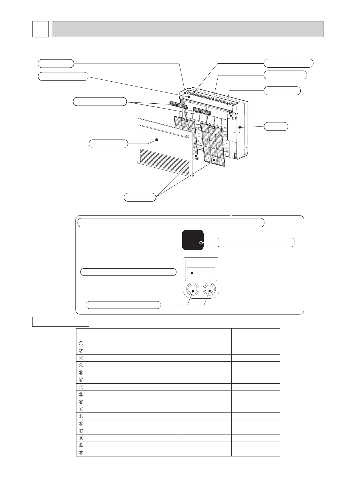
PART NAMES AND FUNCTIONS
MFZ-KT25VG MFZ-KT35VG MFZ-KT50VG MFZ-KT60VG
Air outlet
Multi-flow vane
Air cleaning filter
Horizontal vane
Vertical vane
Fan guard
Panel
Front panel
Air filter
Display and operation section (When the front panel is opened)
ACCESSORIES
E.O
SW
Emergency operation switch
Remote control receiving section
Operation indicator lamp
Model MFZ-KT25/35/50VG MFZ-KT60VG
Remote controller holder 1 1
Fixing screw for 1 3.5 x 16 mm (Black) 2 2
Pipe cover 1 1
Band 2 2
Battery (AAA) for remote controller 2 2
Indoor unit mounting bracket 1 1
Fixing screw for 6 4 x 25 mm 5 5
Wood screw for the indoor unit xation 4 4
Washer of 8 4 4
Felt tape (Used for left or left-rear piping) 1 1
Wireless remote controller 1 1
Air cleaning lter 2 2
Breaker tag 1 1
Breaker notice 1 1
Joint pipe
Pipe cover for joint pipe
7
-
-
1
1
4
OBH843
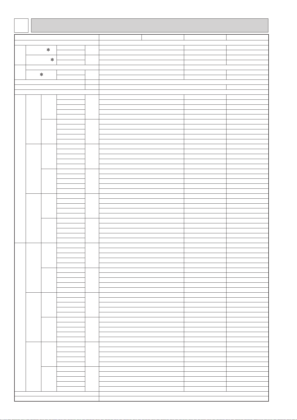
SPECIFICATION
Indoor model
Power supply Single phase 230 V, 50 Hz
Power input 1
Running current 1
Electrical
data
Model RC0J30-Q# RC0J40-P#
Current
Fan
motor
Dimensions W × H × D mm 750 × 600 × 215
Weight kg 14.5 15
Air direction 1 FLOW: 4, 2 FLOW: 4
Special remarks (Single)
Special remarks (Multi)
Fan speed regulator 5
Remote controller model SG191
1
Airow
Sound level
Fan speed
Airow
Sound level
Fan speed
Cooling
Heating 24 52 59
Cooling
Heating 0.20 0.45 0.49
Cooling
Heating 0.17 0.43 0.46
Super High
High 468 624 738
Med. 390 516 576
Cooling
Low 288 402 480
Silent 234 336 336
Super High
High 438 696 750
Med. 336 564 582
Heating
Low 240 462 462
Silent 210 360 360
Super High
High 37 42 46
Med. 31 37 40
Cooling
Low 24 32 36
Silent 19 28 28
Super High
High 37 44 47
Med. 30 40 41
Heating
Low 23 35 35
Silent 19 29 29
Super High
High 900 970 1120
Med. 770 820 900
Cooling
Low 610 670 770
Silent 520 580 580
Super High
High 850 1060 1130
Med. 690 890 910
Heating
Low 530 750 750
Silent 480 610 610
Super High
High 468 624 738
Med. 390 516 576
Cooling
Low 288 402 480
Silent 252 336 336
Super High
High 468 696 750
Med. 378 564 582
Heating
Low 294 462 462
Silent 252 360 360
Super High
High 38 42 46
Med. 33 37 40
Cooling
Low 28 32 36
Silent 23 28 28
Super High
High 39 44 47
Med. 34 40 41
Heating
Low 28 35 35
Silent 24 29 29
Super High
High 900 970 1120
Med. 770 820 900
Cooling
Low 610 670 770
Silent 550 580 580
Super High
High 900 1060 1130
Med. 750 890 910
Heating
Low 620 750 750
Silent 550 610 610
W
A
A
3
m
3
m
dB(A)
dB(A)
rpm
rpm
3
m
3
m
dB(A)
dB(A)
rpm
rpm
/h
/h
/h
/h
MFZ-KT25VG MFZ-KT35VG MFZ-KT50VG MFZ-KT60VG
20 37 63
0.17 0.34 0.55
0.14 0.32 0.52
534 738 900
582 840 876
41 48 53
44 49 51
1000 1120 1330
1080 1250 1300
540 738 900
582 840 876
43 48 53
44 49 51
1010 1120 1330
1080 1250 1300
8
NOTE: Test conditions are based on ISO 5151.
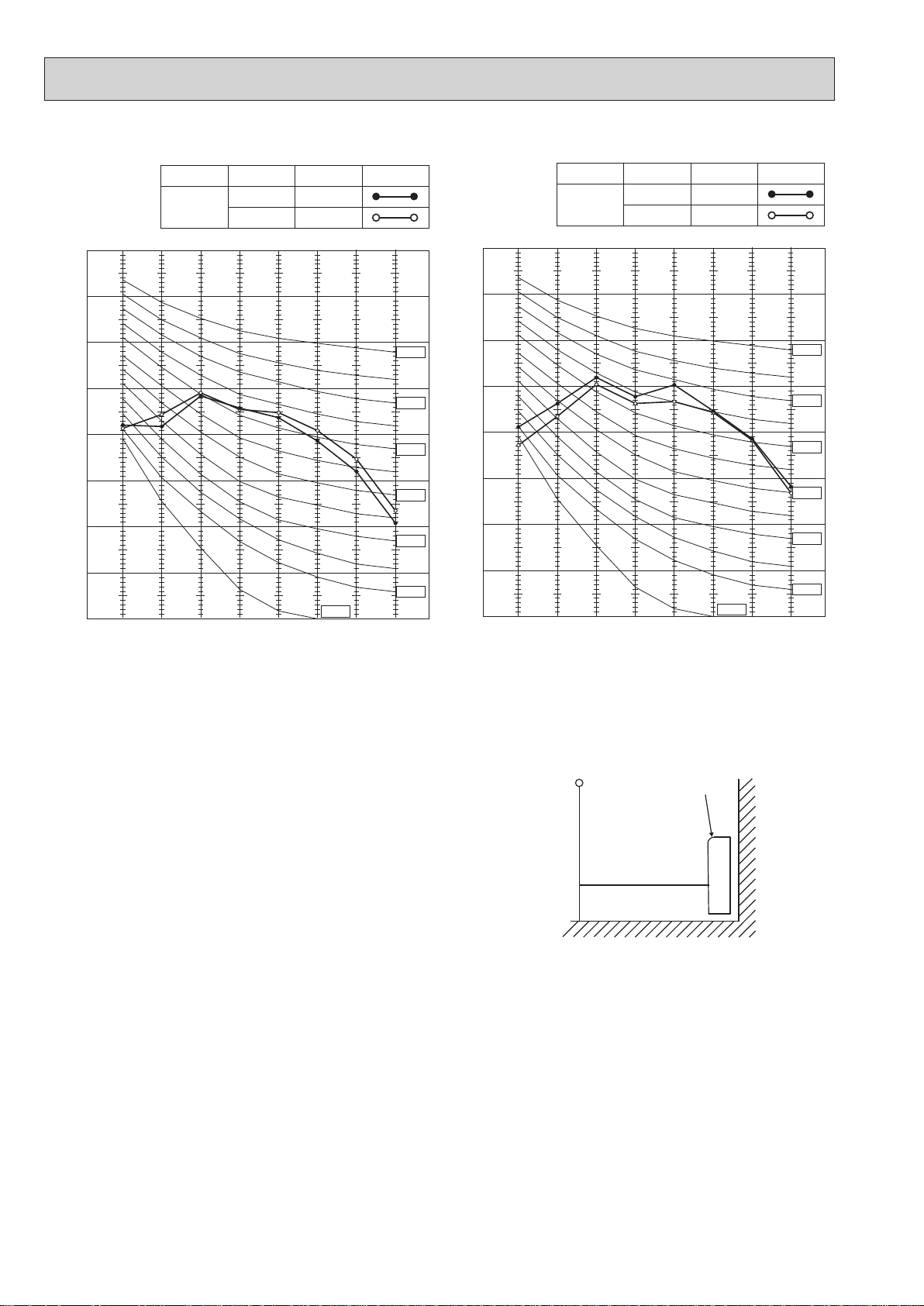
OCTAVE BAND SOUND PRESSURE LEVEL, dB re 0.0002 MICRO BAR
OCTAVE BAND SOUND PRESSURE LEVEL, dB re 0.0002 MICRO BAR
OBH843
Cooling: Indoor Dry-bulb temperature 27°C Wet-bulb temperature 19°C
Outdoor Dry-bulb temperature 35°C
Heating: Indoor Dry-bulb temperature 20°C
Outdoor Dry-bulb temperature 7°C Wet-bulb temperature 6°C
1 Measured under rated operating frequency.
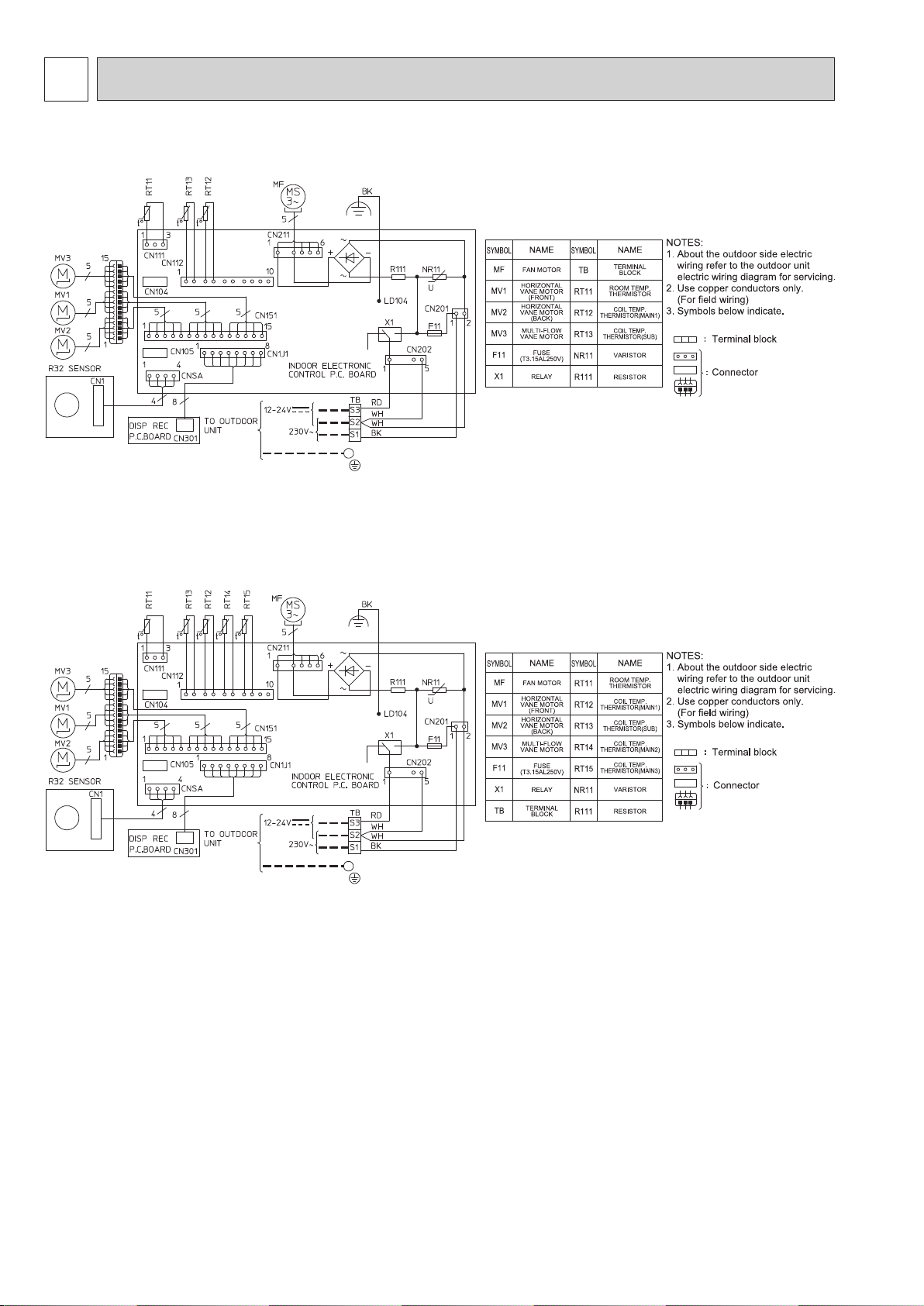
Specifications and rating conditions of main electric parts
Model
Item
Fuse (F11) T3.15AL250V
Horizontal vane motor (Front) (MV1) 12 V DC 250 Ω
Horizontal vane motor (Back) (MV2) 12 V DC 250 Ω
Multi-ow vane motor (MV3) 12 V DC 350 Ω
Terminal block (TB) 3P
Varistor (NR11) S10K300E2K1
MFZ-KT25VG MFZ-KT35VG MFZ-KT50VG MFZ-KT60VG
5
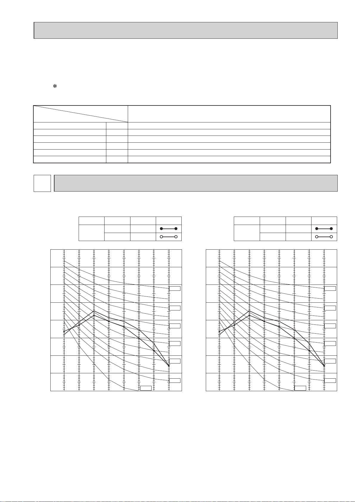
NOISE CRITERIA CURVES
MFZ-KT25VG MFZ-KT35VG
FAN SPEED
Super High
80
70
60
50
40
30
20
FUNCTION
COOLING
HEATING
SPL(dB(A))
41
44
LINE
NC-70
NC-60
NC-50
NC-40
NC-30
80
70
60
50
40
30
20
FAN SPEED
Super High
FUNCTION
COOLING
HEATING
SPL(dB(A))
41
44
LINE
NC-70
NC-60
NC-50
NC-40
NC-30
10
0
63 125 250 500 1000 2000 4000 8000
BAND CENTER FREQUENCIES, Hz
NC-10
NC-20
10
NC-20
0
63 125 250 500 1000 2000 4000 8000
BAND CENTER FREQUENCIES, Hz
NC-10
9
OCTAVE BAND SOUND PRESSURE LEVEL, dB re 0.0002 MICRO BAR
MFZ-KT50VG
OCTAVE BAND SOUND PRESSURE LEVEL, dB re 0.0002 MICRO BAR
OBH843
MFZ-KT60VG
FAN SPEED
Super High
80
70
60
50
40
30
20
10
0
63 125 250 500 1000 2000 4000 8000
BAND CENTER FREQUENCIES, Hz
FUNCTION
COOLING
HEATING
SPL(dB(A))
48
49
NC-10
LINE
NC-70
NC-60
NC-50
NC-40
NC-30
NC-20
FAN SPEED
Super High
80
70
60
50
40
30
20
10
0
63 125 250 500 1000 2000 4000 8000
BAND CENTER FREQUENCIES, Hz
FUNCTION
COOLING
HEATING
SPL(dB(A))
LINE
53
51
NC-70
NC-60
NC-50
NC-40
NC-30
NC-20
NC-10
Test conditions
Cooling : Dry-bulb temperature 27 °C Wet-bulb temperature 19 °C
Heating : Dry-bulb temperature 20 °C
MICROPHONE
INDOOR UNIT
1m
WALL
1m
10
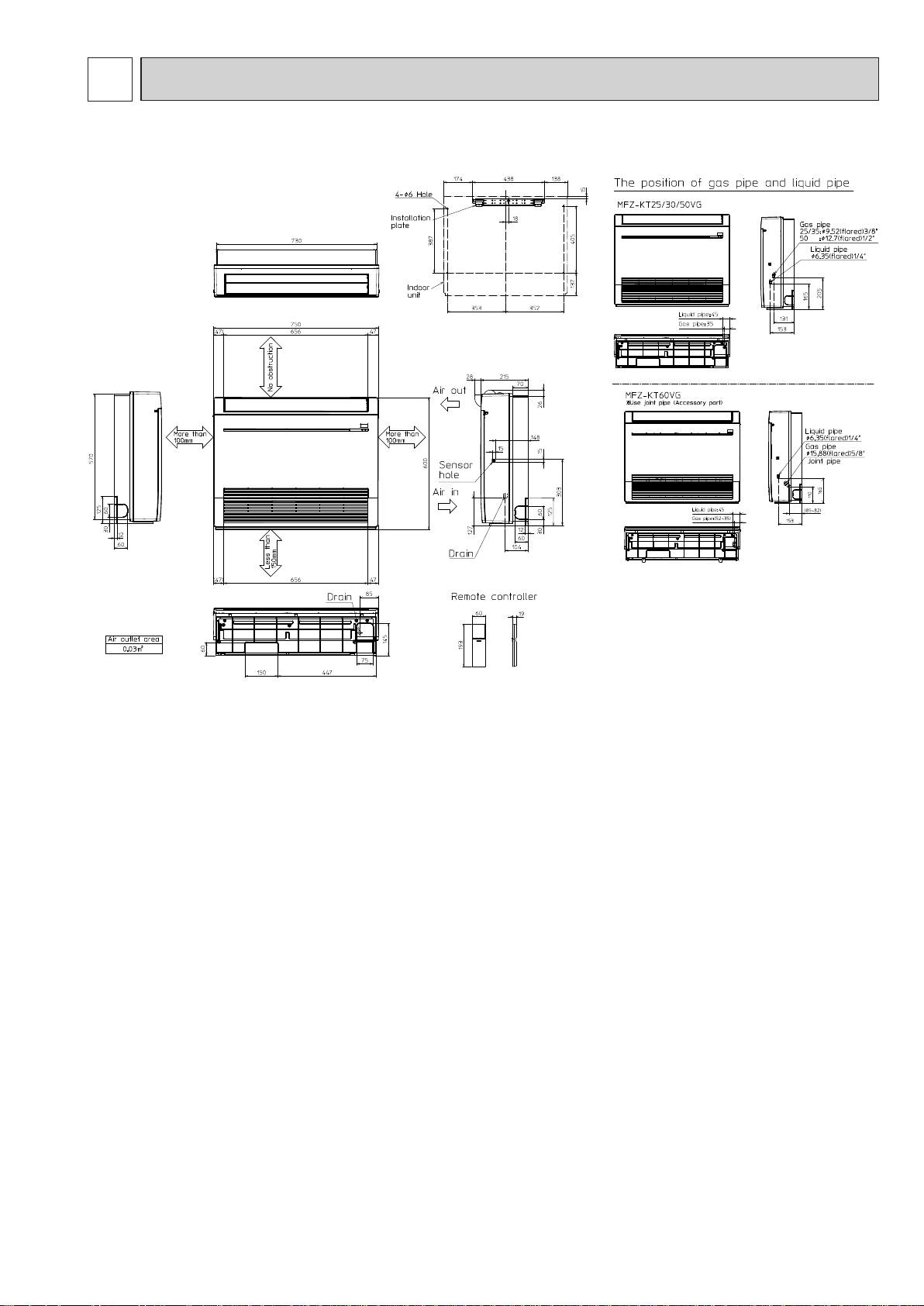
6
OBH843
OUTLINES AND DIMENSIONS
MFZ-KT25VG MFZ-KT35VG MFZ-KT50VG MFZ-KT60VG
Unit: mm
11
7
OBH843
MFZ-KT25VG MFZ-KT35VG MFZ-KT50VG
WIRING DIAGRAM
MFZ-KT60VG
12
8
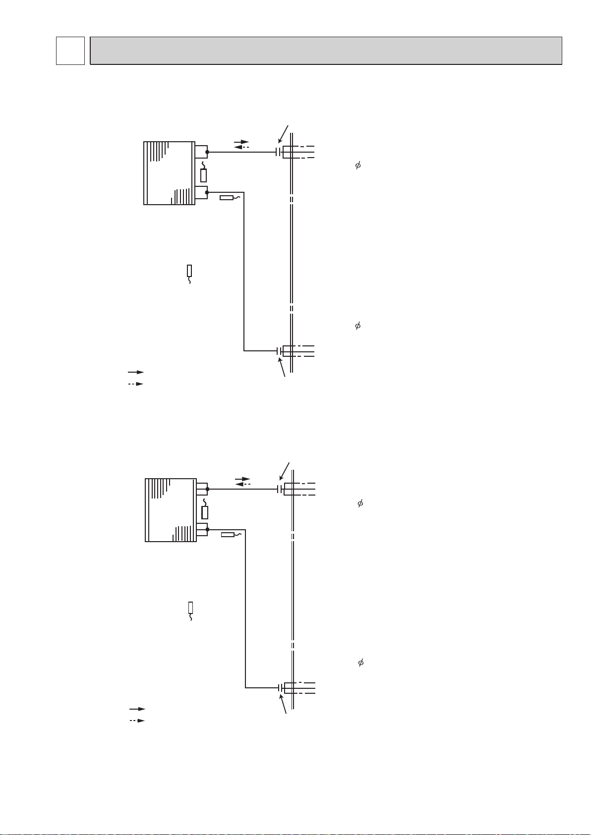
OBH843
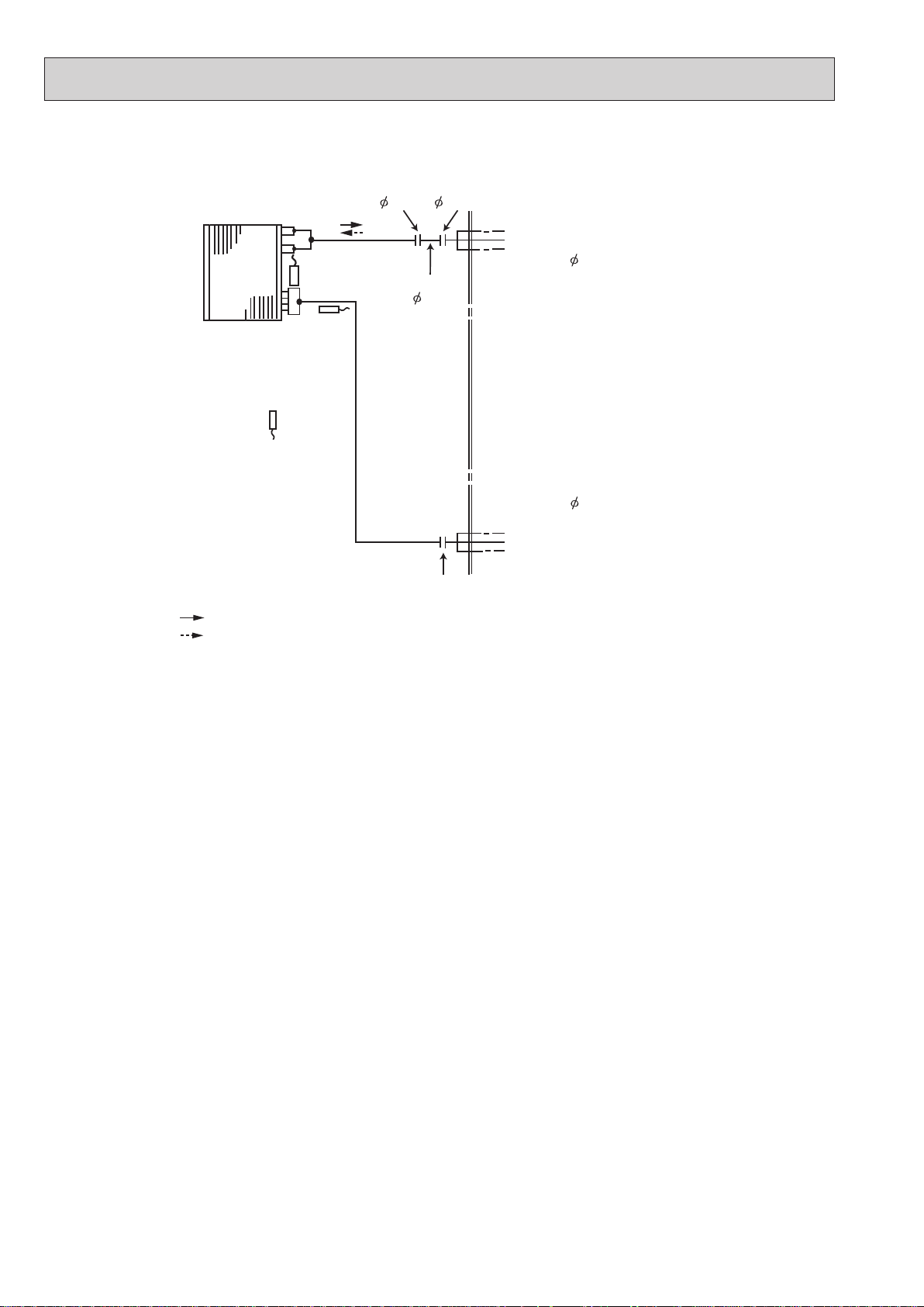
REFRIGERANT SYSTEM DIAGRAM
MFZ-KT25VG MFZ-KT35VG
Indoor
heat
exchanger
Indoor coil
thermistor
RT13 (sub)
Room temperature
thermistor
RT11
Refrigerant flow in cooling
Refrigerant flow in heating
Indoor coil
thermistor
RT12 (main)
Distributor
Unit: mm
Flared connection
Refrigerant pipe 9.52
(with heat insulator)
Refrigerant pipe 6.35
(with heat insulator)
Flared connection
MFZ-KT50VG
Indoor
heat
exchanger
Room temperature
thermistor
RT11
Refrigerant flow in cooling
Refrigerant flow in heating
Indoor coil
thermistor
RT12 (main)
Distributor
Indoor coil
thermistor
RT13 (sub)
Flared connection
Refrigerant pipe 12.7
(with heat insulator)
Refrigerant pipe 6.35
(with heat insulator)
Flared connection
13
MFZ-KT60VG
OBH843
Unit: mm
Flared connection
( 12.7) ( 15.88)
Indoor
heat
exchanger
Room temperature
thermistor
RT11
Refrigerant flow in cooling
Refrigerant flow in heating
Indoor coil
thermistor
RT12 (main)
Distributor
Indoor coil
thermistor
RT14, RT15
(main)
RT13 (sub)
Joint pipe
( 12.7)
Flared connection
Refrigerant pipe 15.88
(with heat insulator)
Refrigerant pipe 6.35
(with heat insulator)
14
 Loading...