

Mitsubishi Electric SUZ-M25VA, SUZ-M25VA-ET, SUZ-M50VA-ET, SUZ-M60VA, SUZ-M60VA-ET Service Manual
...Page 1
TECHNICAL & SERVICE MANUAL
R32
[Model Name]
SUZ-M25VA
SUZ-M25VA-ET
SUZ-M35VA
SUZ-M35VA-ET
SUZ-M50VA
SUZ-M50VA-ET
SUZ-M60VA
SUZ-M60VA-ET
SUZ-M71VA
SUZ-M71VA-ET
CONTENTS
1.
COMBINATION OF INDOOR AND OUTDOOR UNITS
.....
2
2. SAFETY PRECAUTION
....................................
2
3. PARTS NAMES AND FUNCTIONS
................
10
4. SPECIFICATION
...............................................
11
5. NOISE CRITERIA CURVES
............................
13
6. OUTLINES AND DIMENSIONS
......................
14
7. WIRING DIAGRAM
..........................................
16
8. REFRIGERANT SYSTEM DIAGRAM
.............
20
9. ACTUATOR CONTROL
...................................
23
10. SERVICE FUNCTIONS
....................................
24
11. TROUBLESHOOTING
.....................................
24
12. DISASSEMBLY PROCEDURE
........................
41
Note:
•This service manual
describes service data of
the outdoor units only.
HFC
utilized
R32
SUZ-M25VA.TH
SUZ-M35VA.TH
PARTS CATALOG (OCB684)
No. OCH684
December 2018
SPLIT-TYPE, HEAT PUMP AIR CONDITIONERS
[Service Ref.]
SUZ-M25VA.TH
SUZ-M25VA-ET.TH
SUZ-M35VA.TH
SUZ-M35VA-ET.TH
SUZ-M50VA.TH
SUZ-M50VA-ET.TH
SUZ-M60VA.TH
SUZ-M60VA-ET.TH
SUZ-M71VA.TH
SUZ-M71VA-ET.TH
Page 2
2
OCH684
1
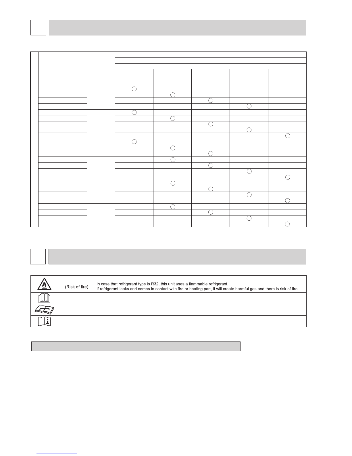
COMBINATION OF INDOOR AND OUTDOOR UNITS
INDOOR UNIT SERVICE MANUAL
Indoor unit
Outdoor unit
Heat pump type
SUZ-
Service Ref.
Service
manual No.
M25VA.TH
M25VA-ET.TH
M35VA.TH
M35VA-ET.TH
M50VA.TH
M50VA-ET.TH
M60VA.TH
M60VA-ET.TH
M71VA.TH
M71VA-ET.TH
Heat pump without electric heater
SLZ-M25FA.TH
OCH522A
OCB522A
─ ─ ─ ─
SLZ-M35FA.TH ─ ─ ─ ─
SLZ-M50FA.TH ─ ─ ─ ─
SLZ-M60FA.TH ─ ─ ─ ─
SEZ-M25VA.TH
─
─ ─ ─ ─
SEZ-M35VA.TH ─ ─ ─ ─
SEZ-M50VA.TH ─ ─ ─ ─
SEZ-M60VA.TH ─ ─ ─ ─
SEZ-M71VA.TH ─ ─ ─ ─
MLZ-KP25VF-E1
OBH801
OBB801
─ ─ ─ ─
MLZ-KP35VF-E1 ─ ─ ─ ─
MLZ-KP50VF-E1 ─ ─ ─ ─
PLA-M35EA.UK
OCH697
OCB697
─ ─ ─ ─
PLA-M50EA.UK ─ ─ ─ ─
PLA-M60EA.UK ─ ─ ─ ─
PLA-M71EA.UK ─ ─ ─ ─
PCA-M35KA
OCH659
OCB659
─ ─ ─ ─
PCA-M50KA ─ ─ ─ ─
PCA-M60KA ─ ─ ─ ─
PCA-M71KA ─ ─ ─ ─
PEAD-M35JA(L).UK
BWE017010
─ ─ ─ ─
PEAD-M50JA(L).UK ─ ─ ─ ─
PEAD-M60JA(L).UK ─ ─ ─ ─
PEAD-M71JA(L).UK ─ ─ ─ ─
2-1. ALWAYS OBSERVE FOR SAFETY
Before obtaining access to terminal, all supply circuits must be disconnected.
2
SAFETY PRECAUTION
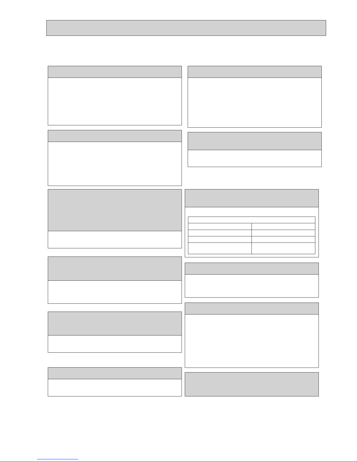
MEANINGS OF SYMBOLS DISPLAYED ON THE UNIT
WARNING
This mark is for R32 refrigerant only. Refrigerant type is written on nameplate of outdoor unit.
Read the OPERATION MANUAL carefully before operation.
Service personnel are required to carefully read the OPERATION MANUAL and INSTALLATION MANUAL before operation.
Further information is available in the OPERATION MANUAL, INSTALLATION MANUAL, and the like.
Page 3
3
OCH684
3
2-2. CAUTIONS RELATED TO NEW REFRIGERANT
Cautions for units utilizing refrigerant R32
Precautions during the repair service
• Do not perform the work involving the electric parts
with wet hands.
• Do not pour water into the electric parts.
• Do not touch the refrigerant.
•
Do not touch the hot or cold areas in the refrigerating cycle.
• When the repair or the inspection of the circuit needs
to be done without turning off the power, exercise great
caution not to touch the live parts.
Use a vacuum pump with a reverse ow check
valve.
Vacuum pump oil may ow back into refrigerant cycle
and that can cause deterioration of refrigerant oil, etc.
Use new refrigerant pipes.
In case of using the existing pipes for R22, be careful
with the following.
· Be sure to clean the pipes and make sure that the
insides of the pipes are clean.
· Change are nut to the one provided with this product.
Use a newly ared pipe.
· Avoid using thin pipes.
Preparation before the repair service
• Prepare the proper tools.
• Prepare the proper protectors.
• Provide adequate ventilation.
• After stopping the operation of the air conditioner, turn
off the power-supply breaker.
• Discharge the condenser before the work involving the
electric parts.
Handle tools with care.
If dirt, dust or moisture enters into refrigerant cycle, that
can cause deterioration of refrigerant oil or malfunction of
compressor.
Use the specied refrigerant only.
Never use any refrigerant other than that specied.
Doing so may cause a burst, an explosion, or re when
the unit is being used, serviced, or disposed of.
Correct refrigerant is specied in the manuals and on the
spec labels provided with our products.
We will not be held responsible for mechanical failure,
system malfunction, unit breakdown or accidents caused
by failure to follow the instructions.
Ventilate the room if refrigerant leaks during
operation. If refrigerant comes into contact with
a ame, poisonous gases will be released.
Use the following tools specically designed for
use with R32 refrigerant.
The following tools are necessary to use R32 refrigerant.
Tools for R32
Gauge manifold Flare tool
Charge hose Size adjustment gauge
Gas leak detector Vacuum pump adaptor
Torque wrench Electronic refrigerant
charging scale
Make sure that the inside and outside of
refrigerant piping is clean and it has no
contaminants such as sulfur, oxides, dirt,
shaving particles, etc, which are hazard to
refrigerant cycle.
In addition, use pipes with specied thickness.
Contamination inside refrigerant piping can cause deterioration of refrigerant oil, etc.
Store the piping indoors, and keep both ends of
the piping sealed until just before brazing.
(Leave elbow joints, etc. in their packaging.)
If dirt, dust or moisture enters into refrigerant cycle, that
can cause deterioration of refrigerant oil or malfunction of
compressor.
The refrigerant oil applied to are and ange
connections must be ester oil, ether oil or
alkylbenzene oil in a small amount.
If large amount of mineral oil enters, that can cause
deterioration of refrigerant oil, etc.
Do not use refrigerant other than R32.
If other refrigerant (R22, etc.) is used, chlorine in
refrigerant can cause deterioration of refrigerant oil, etc.
Page 4

4
OCH684
[1] Warning for service
(1) Do not alter the unit.
(2) For installation and relocation work, follow the instructions in the Installation Manual and use tools and pipe
components specifically made for use with refrigerant specified in the outdoor unit installation manual.
(3) Ask a dealer or an authorized technician to install, relocate and repair the unit.
For appliances not accessible to the general public.
(4) Refrigerant pipes connection shall be accessible for maintenance purposes.
(5)
If the air conditioner is installed in a small room or closed room, measures must be taken to prevent the refrigerant
concentration in the room from exceeding the safety limit in the event of refrigerant leakage. Should the refrigerant
leak and cause the concentration limit to be exceeded, hazards due to lack of oxygen in the room may result.
(6) Keep gas-burning appliances, electric heaters, and other fire sources (ignition sources) away from the location
where installation, repair, and other air conditioner work will be performed.
If refrigerant comes into contact with a flame, poisonous gases will be released.
(7) When installing or relocating, or servicing the air conditioner, use only the specified refrigerant (R32) to charge
the refrigerant lines.
Do not mix it with any other refrigerant and do not allow air to remain in the lines.
If air is mixed with the refrigerant, then it can be the cause of abnormal high pressure in the refrigerant line, and
may result in an explosion and other hazards.
(8) After installation has been completed, check for refrigerant leaks. If refrigerant leaks into the room and comes
into contact with the flame of a heater or portable cooking range, poisonous gases will be released.
(9) Do not use low temperature solder alloy in case of brazing the refrigerant pipes.
(10)
When performing brazing work, be sure to ventilate the room sufficiently. Make sure that there are no hazardous
or flammable materials nearby.
When performing the work in a closed room, small room, or similar location, make sure that there are no refriger-
ant leaks before performing the work.
If refrigerant leaks and accumulates, it may ignite or poisonous gases may be released.
(11) Do not install the unit in places where refrigerant may build-up or places with poor ventilation such as a semi-base-
ment or a sunken place in outdoor: Refrigerant is heavier than air, and inclined to fall away from the leak source.
(12)
Do not use means to accelerate the defrosting process or to clean, other than those recommended by the manu-
facturer.
(13)
The appliance shall be stored in a room without continuously operating ignition sources (for example: open
flames, an operating gas appliance or an operating electric heater).
(14)
Do not pierce or burn.
(15)
Be aware that refrigerants may not contain an odour.
(16)
Pipe-work shall be protected from physical damage.
(17)
The installation of pipe-work shall be kept to a minimum.
(18)
Compliance with national gas regulations shall be observed.
(19)
Keep any required ventilation openings clear of obstruction.
(20)
Servicing shall be performed only as recommended by the manufacturer.
(21)
The appliance shall be stored in a well-ventilated area where the room size corresponds to the room area as
specified for operation.
(22) Maintenance, service and repair operations shall be performed by authorized technician with required qualification.
(23)
Be sure to have appropriate ventilation in order to prevent ignition. Furthermore, be sure to carry out fire preven-
tion measures that there are no dangerous or flammable objects in the surrounding area.
Page 5

5
OCH684
[2] Cautions for unit using R32 refrigerant
Basic work procedures are the same as those for conventional units using refrigerant R410A. However, pay careful
attention to the following points.
(1) Information on servicing
(1-1) Checks on the Area
Prior to beginning work on systems containing flammable refrigerants, safety checks are necessary to ensure that the
risk of ignition is minimized.
For repair to the refrigerating systems, (1-3) to (1-7) shall be completed prior to conducting work on the systems.
(1-2) Work Procedure
Work shall be undertaken under a controlled procedure so as to minimize the risk of a flammable gas or vapor being
present while the work is being performed.
(1-3) General Work Area
All maintenance staff and others working in the local area shall be instructed on the nature of work being carried out.
Work in confined spaces shall be avoided. The area around the workspace shall be sectioned off. Ensure that the conditions within the area have been made safe by control of flammable material.
(1-4) Checking for Presence of Refrigerant
The area shall be checked with an appropriate refrigerant detector prior to and during work, to ensure the technician is
aware of potentially toxic or flammable atmospheres. Ensure that the leak detection equipment being used is suitable
for use with all applicable refrigerants, i.e. non-sparking, adequately sealed or intrinsically safe.
(1-5) Presence of Fire Extinguisher
If any hot work is to be conducted on the refrigeration equipment or any associated parts, appropriate fire extinguishing
equipment shall be available to hand.
Have a dry powder or CO2 fire extinguisher adjacent to the charging area.
(1-6) No Ignition Sources
No person carrying out work in relation to a refrigeration system which involves exposing any pipe work shall use any
sources of ignition in such a manner that it may lead to the risk of fire or explosion. All possible ignition sources, including cigarette smoking, should be kept sufficiently far away from the site of installation, repairing, removing and disposal,
during which refrigerant can possibly be released to the surrounding space. Prior to work taking place, the area around
the equipment is to be surveyed to make sure that there are no flammable hazards or ignition risks. “No Smoking” signs
shall be displayed.
(1-7) Ventilated Area
Ensure that the area is in the open or that it is adequately ventilated before breaking into the system or conducting any
hot work. A degree of ventilation shall continue during the period that the work is carried out. The ventilation should
safely disperse any released refrigerant and preferably expel it externally into the atmosphere.
(1-8) Checks on the Refrigeration Equipment
Where electrical components are being changed, they shall be fit for the purpose and to the correct specification. At all
times the manufacturer’s maintenance and service guidelines shall be followed. If in doubt, consult the manufacturer’s
technical department for assistance.
The following checks shall be applied to installations using flammable refrigerants:
•
The charge size is in accordance with the room size within which the refrigerant containing parts are installed.
•
The ventilation machinery and outlets are operating adequately and are not obstructed.
•
Marking to the equipment continues to be visible and legible. Markings and signs that are illegible shall be corrected.
•
Refrigeration pipe or components are installed in a position where they are unlikely to be exposed to any substance
which may corrode refrigerant containing components, unless the components are constructed of materials which are
inherently resistant to being corroded or are suitably protected against being corroded.
(1-9) Checks on Electrical Devices
Repair and maintenance to electrical components shall include initial safety checks and component inspection procedures. If a fault exists that could compromise safety, then no electrical supply shall be connected to the circuit until it is
satisfactorily dealt with. If the fault cannot be corrected immediately but it is necessary to continue operation, an adequate temporary solution shall be used. This shall be reported to the owner of the equipment so all parties are advised.
Initial safety checks shall include that:
•
capacitors are discharged: this shall be done in a safe manner to avoid possibility of sparking;
•
no live electrical components and wiring are exposed while charging, recovering or purging the system;
•
there is continuity of earth bonding
(2) Repairs to Sealed Components
(2-1) During repairs to sealed components, all electrical supplies shall be disconnected from the equipment being worked
upon prior to any removal of sealed covers, etc. If it is absolutely necessary to have an electrical supply to equipment
during servicing, then a permanently operating form of leak detection shall be located at the most critical point to warn
of a potentially hazardous situation.
(2-2) Particular attention shall be paid to the following to ensure that by working on electrical components, the casing is not
altered in such a way that the level of protection is affected. This shall include damage to cables, excessive number of
connections, terminals not made to original specification, damage to seals, incorrect fitting of glands, etc.
Ensure that the apparatus is mounted securely.
Ensure that seals or sealing materials have not degraded to the point that they no longer serve the purpose of preventing the ingress of flammable atmospheres.
Replacement parts shall be in accordance with the manufacturer’s specifications.
Page 6

6
OCH684
(3) Repair to intrinsically Safe Components
Do not apply any permanent inductive or capacitance loads to the circuit without ensuring that this will not exceed the
permissible voltage and current permitted for the equipment in use.
Intrinsically safe components are the only types that can be worked on while live in the presence of a flammable atmosphere. The test apparatus shall be at the correct rating.
Replace components only with parts specified by the manufacturer. Other parts may result in the ignition of refrigerant in
the atmosphere from a leak.
(4) Cabling
Check that cabling will not be subject to wear, corrosion, excessive pressure, vibration, sharp edges or any other adverse
environmental effects. The check shall also take into account the effects of aging or continual vibration from sources such
as compressors or fans.
(5) Detection of Flammable Refrigerants
Under no circumstances shall potential sources of ignition be used in the searching for or detection of refrigerant leaks.
A halide torch (or any other detector using a naked flame) shall not be used.
(6) Leak Detection Methods
Electronic leak detectors may be used to detect refrigerant leaks but, in the case of flammable refrigerants, the sensitivity
may not be adequate, or may need re-calibration. (Detection equipment shall be calibrated in a refrigerant-free area.)
Ensure that the detector is not a potential source of ignition and is suitable for the refrigerant used. Leak detection equipment shall be set at a percentage of the LFL of the refrigerant and shall be calibrated to the refrigerant employed, and the
appropriate percentage of gas (25% maximum) is confirmed.
Leak detection fluids are suitable for use with most refrigerants but the use of detergents containing chlorine shall be
avoided as the chlorine may react with the refrigerant and corrode the copper pipe-work.
If a leak is suspected, all naked flames shall be removed/extinguished.
If a leakage of refrigerant is found which requires brazing, all of the refrigerant shall be recovered from the system, or
isolated (by means of shut off valves) in a part of the system remote from the leak. For appliances containing flammable
refrigerants, oxygen free nitrogen (OFN) shall then be purged through the system both before and during the brazing process.
(7) Removal and Evacuation
When breaking into the refrigerant circuit to make repairs – or for any other purpose conventional procedures shall be
used. However, for flammable refrigerants it is important that best practice is followed since flammability is a consideration. The following procedure shall be adhered to:
• remove refrigerant
• purge the circuit with inert gas
• evacuate
• purge again with inert gas
• open the circuit by cutting or brazing.
The refrigerant charge shall be recovered into the correct recovery cylinders. For appliances containing flammable refrigerants, the system shall be “flushed” with OFN to render the unit safe. This process may need to be repeated several
times.
Compressed air or oxygen shall not be used for purging refrigerant systems.
For appliances containing flammable refrigerants, flushing shall be achieved by breaking the vacuum in the system with
OFN and continuing to fill until the working pressure is achieved, then venting to atmosphere, and finally pulling down to
a vacuum. This process shall be repeated until no refrigerant is within the system. When the final OFN charge is used,
the system shall be vented down to atmospheric pressure to enable work to take place. This operation is absolutely vital
if brazing operations on the pipe-work are to take place.
Ensure that the outlet for the vacuum pump is not close to any ignition sources and that ventilation is available.
(8) Charging Procedures
In addition to conventional charging procedures, the following requirements shall be followed:
•
Ensure that contamination of different refrigerants does not occur when using charging equipment. Hoses or lines
shall be as short as possible to minimize the amount of refrigerant contained in them.
•
Cylinders shall be kept upright.
•
Ensure that the refrigeration system is earthed prior to charging the system with refrigerant.
•
Label the system when charging is complete (if not already).
•
Extreme care shall be taken not to overfill the refrigeration system.
Prior to recharging the system, it shall be pressure-tested with the appropriate purging gas. The system shall be leaktested on completion of charging but prior to commissioning. A follow up leak test shall be carried out prior to leaving the
site.
(9) Decommissioning
Before carrying out this procedure, it is essential that the technician is completely familiar with the equipment and all its
detail. It is recommended good practice that all refrigerants are recovered safely. Prior to the task being carried out, an
oil and refrigerant sample shall be taken in case analysis is required prior to re-use of reclaimed refrigerant. It is essential
that electrical power is available before the task is commenced.
a) Become familiar with the equipment and its operation.
Page 7

7
OCH684
b) Isolate system electrically.
c) Before attempting the procedure, ensure that:
• mechanical handling equipment is available, if required, for handling refrigerant cylinders;
• all personal protective equipment is available and being used correctly;
• the recovery process is supervised at all times by a competent person;
• recovery equipment and cylinders conform to the appropriate standards.
d) Pump down refrigerant system, if possible.
e) If a vacuum is not possible, make a manifold so that refrigerant can be removed from various parts of the system.
f) Make sure that cylinder is situated on the scales before recovery takes place.
g) Start the recovery machine and operate in accordance with manufacturer’s instructions.
h) Do not overfill cylinders. (No more than 80 % volume liquid charge).
i) Do not exceed the maximum working pressure of the cylinder, even temporarily.
j) When the cylinders have been filled correctly and the process completed, make sure that the cylinders and the equip-
ment are removed from site promptly and all isolation valves on the equipment are closed off.
k) Recovered refrigerant shall not be charged into another refrigeration system unless it has been cleaned and checked.
(10) Labelling
Equipment shall be labelled stating that it has been de-commissioned and emptied of refrigerant. The label shall be
dated and signed. For appliances containing flammable refrigerants, ensure that there are labels on the equipment stating the equipment contains flammable refrigerant.
(11) Recovery
When removing refrigerant from a system, either for servicing or decommissioning, it is recommended good practice
that all refrigerants are removed safely. When transferring refrigerant into cylinders, ensure that only appropriate refrigerant recovery cylinders are employed. Ensure that the correct number of cylinders for holding the total system charge
are available. All cylinders to be used are designated for the recovered refrigerant and labelled for that refrigerant (i.e.
special cylinders for the recovery of refrigerant). Cylinders shall be complete with pressure-relief valve and associated
shut-off valves in good working order. Empty recovery cylinders are evacuated and, if possible, cooled before recovery
occurs.
The recovery equipment shall be in good working order with a set of instructions concerning the equipment that is at
hand and shall be suitable for the recovery of all appropriate refrigerants including, when applicable, flammable refrigerants. In addition, a set of calibrated weighing scales shall be available and in good working order. Hoses shall be complete with leak-free disconnect couplings and in good condition. Before using the recovery machine, check that it is in
satisfactory working order, has been properly maintained and that any associated electrical components are sealed to
prevent ignition in the event of a refrigerant release. Consult manufacturer if in doubt.
The recovered refrigerant shall be returned to the refrigerant supplier in the correct recovery cylinder, and the relevant
waste transfer note arranged. Do not mix refrigerants in recovery units and especially not in cylinders. If compressors or
compressor oils are to be removed, ensure that they have been evacuated to an acceptable level to make certain that
flammable refrigerant does not remain within the lubricant. The evacuation process shall be carried out prior to returning
the compressor to the suppliers. Only electric heating to the compressor body shall be employed to accelerate this process. When oil is drained from a system, it shall be carried out safely.
Page 8
8
OCH684
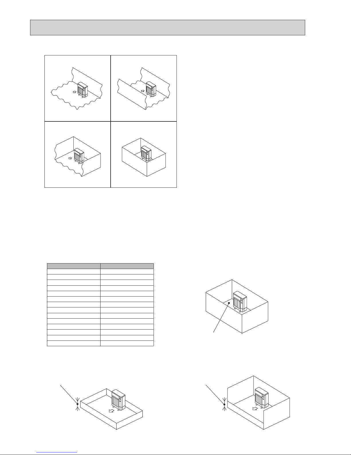
2-3. Choosing the outdoor unit installation location
R32 is heavier than air—as well as other refrigerants—
so tends to accumulate at the base (in the vicinity of the
floor). If R32 accumulates around base, it may reach a
flammable concentration in case room is small. To avoid
ignition, maintaining a safe work environment is required
by ensuring appropriate ventilation. If a refrigerant leak is
confirmed in a room or an area where there is insufficient
ventilation, refrain from using of flames until the work
environment can be improved by ensuring appropriate
ventilation.
Install outdoor units in a place where at least one of the
four sides is open, and in a sufficiently large space without depressions.
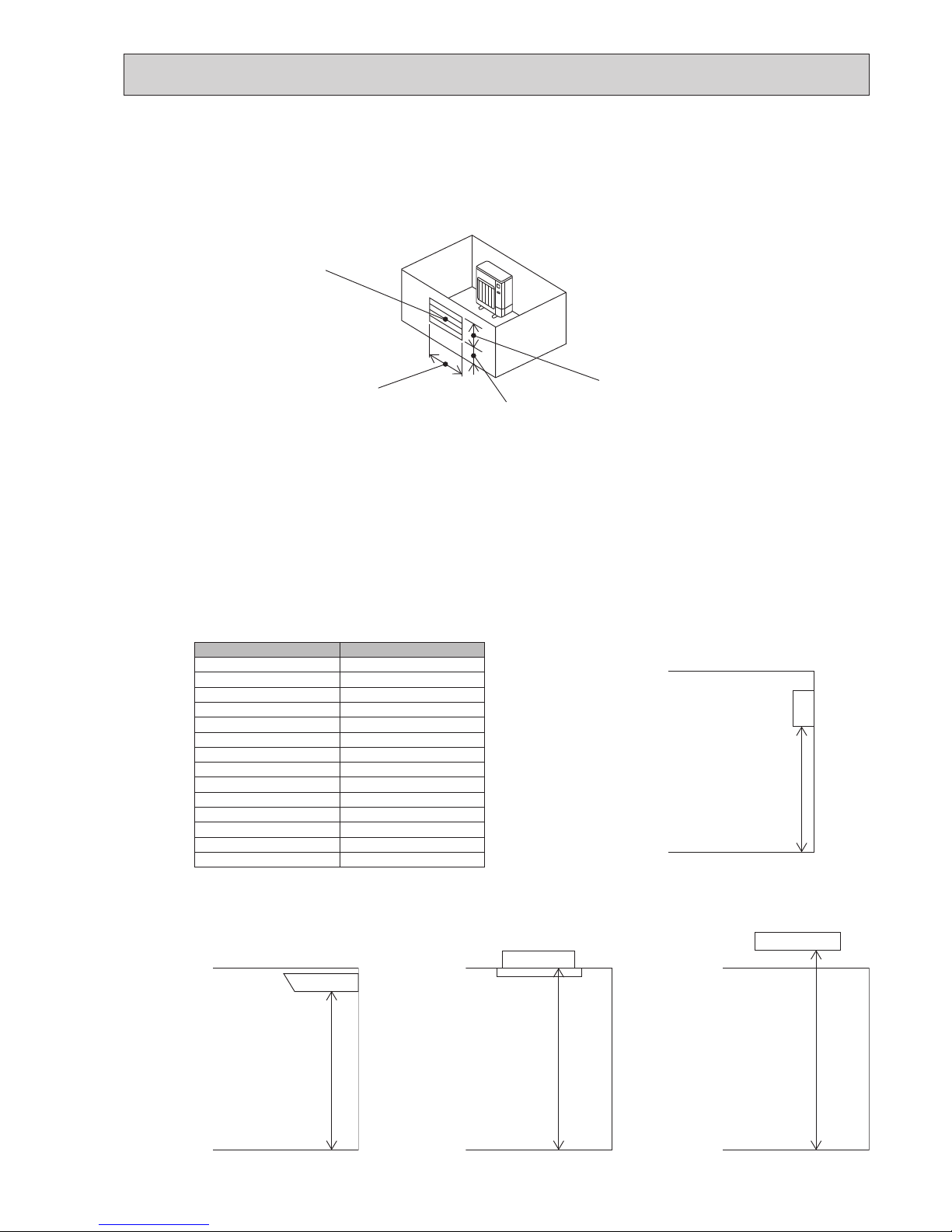
2-4. Minimum installation area
If you unavoidably install a unit in a space where all four sides are blocked or there are depressions, confirm that one of
these situations (A, B or C) is satisfied.
Note: These countermeasures are for keeping safety not for specification guarantee.
A) Secure sufficient installation space (minimum installation area Amin).
Install in a space with an installation area of Amin or more, corresponding to refrigerant quantity M (factory-charged
refrigerant + locally added refrigerant).
B) Install in a space with a depression height of [ 0.125 [m]
OK OK
OK NG
Amin
Height from the bottom of
0.125 [m] or less
Height from the bottom of
0.125 [m] or less
M [kg] Amin [m²]
1.0 12
1.5 17
2.0 23
2.5 28
3.0 34
3.5 39
4.0 45
4.5 50
5.0 56
5.5 62
6.0 67
6.5 73
7.0 78
7.5 84
Page 9
9
OCH684
C) Create an appropriate ventilation open area.
Make sure that the width of the open area is 0.9 [m] or more and the height of the open area is 0.15 [m] or more.
However, the height from the bottom of the installation space to the bottom edge of the open area should be 0.125 [m]
or less.
Open area should be 75% or more opening.
■ Indoor units
Install in a room with a floor area of Amin or more, corresponding to refrigerant quantity M (factory-charged refrigerant + locally added refrigerant).
* For the factory-charged refrigerant amount, refer to the spec nameplate or installation manual.
For the amount to be added locally, refer to the installation manual.
Install the indoor unit so that the height from the floor to the bottom of the indoor unit is h0;
for wall mounted: 1.8 m or more;
for ceiling suspended, cassette and ceiling concealed: 2.2 m or more.
* There are restrictions in installation height for each model, so read the installation manual for the particular unit.
75% or more opening
Width W 0.9 [m] or more
Height from the bottom
0.125 [m] or less
Height H 0.15 [m] or more
M [kg] Amin [m²]
1.0 4
1.5 6
2.0 8
2.5 10
3.0 12
3.5 14
4.0 16
4.5 20
5.0 24
5.5 29
6.0 35
6.5 41
7.0 47
7.5 54
Wall mounted
h0 ] 1.8 [m]
Ceiling concealedCassetteCeiling suspended
h0 ] 2.2 [m]h0 ] 2.2 [m]h0 ] 2.2 [m]
Page 10
10
OCH684
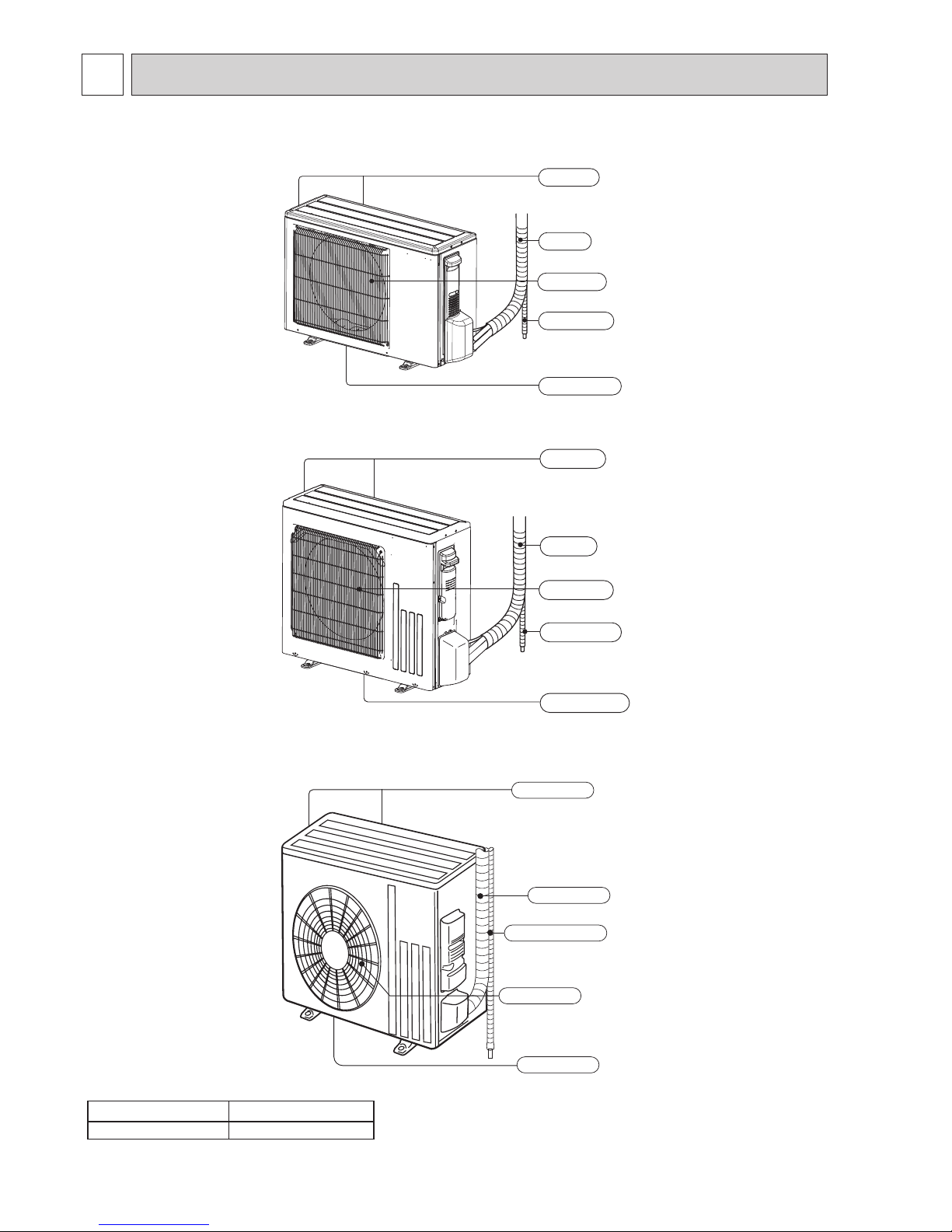
3
PARTS NAMES AND FUNCTIONS
SUZ-M25VA.TH
SUZ-M25VA-ET.TH
SUZ-M35VA.TH
SUZ-M35VA-ET.TH
SUZ-M50VA.TH
SUZ-M50VA-ET.TH
Model SUZ-M·VA
Drain socket 1
Air outlet
Drain outlet
Piping
Drain hose
Air inlet
(back and side)
SUZ-M60VA.TH
SUZ-M60VA-ET.TH
SUZ-M71VA.TH
SUZ-M71VA-ET.TH
Air outlet
Drain outlet
Piping
Drain hose
Air inlet
(back and side)
Piping
Air outlet
Drain outlet
Air inlet
(back and side)
Drain hose
Page 11
11
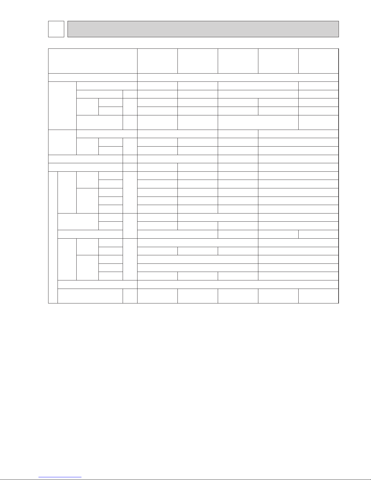
OCH684
SPECIFICATION
4
Note: Test conditions are based on ISO 5151
Cooling : Indoor D.B. 27°C W.B. 19°C
Outdoor D.B. 35°C
Heating : Indoor D.B. 20°C
Outdoor D.B. 7°C W.B. 6°C
Refrigerant piping length (one way): 5 m
*Measured under rated operating frequency.
Outdoor model
SUZ-M25VA
(-ET)
SUZ-M35VA
(-ET)
SUZ-M50VA
(-ET)
SUZ-M60VA
(-ET)
SUZ-M71VA
(-ET)
Power supply Single phase 230 V, 50 Hz
Compressor
Model KVB073FYXMC SV092FBAMT SVB130FBBMT SVB172FCKMT
Output W 470 660 900 1,200
Current*
Cooling
A
2.78 3.90 6.81 7.56 8.26
Heating 3.50 4.77 7.71 8.46 8.66
Refrigeration oil
(Model)
L 0.27 (FW68S) 0.35 (FW68S) 0.35 (FW68S) 0.40 (FW68S)
Fan motor
Model RC0J50-NC RC0J50-RA RC0J60-BC
Current*
Cooling
A
0.22 0.20 0.29 0.84
Heating 0.20 0.23 0.29 0.84
Dimensions W × H × D mm 800 × 550 × 285 800 × 714 × 285 840 × 880 × 330
Weight kg 30 35 41 54
Special remarks
Air
ow*
Cooling
High
m³/h
2,178 2,058 2,748 3,006
Low 1,038 906 1,320 1,716
Heating
High 2,076 1,962 2,622 3,006
Med. 1,788 1,686 2,238 2,892
Low 1,452 1,260 1,704 2,280
Sound pressure level*
Cooling
dB(A)
45 48 49
Heating 46 48 49 51
Sound power level
59 64 65 66
Fan
speed
Cooling
High
rpm
940 840
Low 470 460 490 450
Heating
High 900 840
Med. 780 810
Low 640 600 610 650
Fan speed regulator 3
Refrigerant lling capacity
(R32)
kg 0.65 0.90 1.20 1.25 1.45
Page 12
12
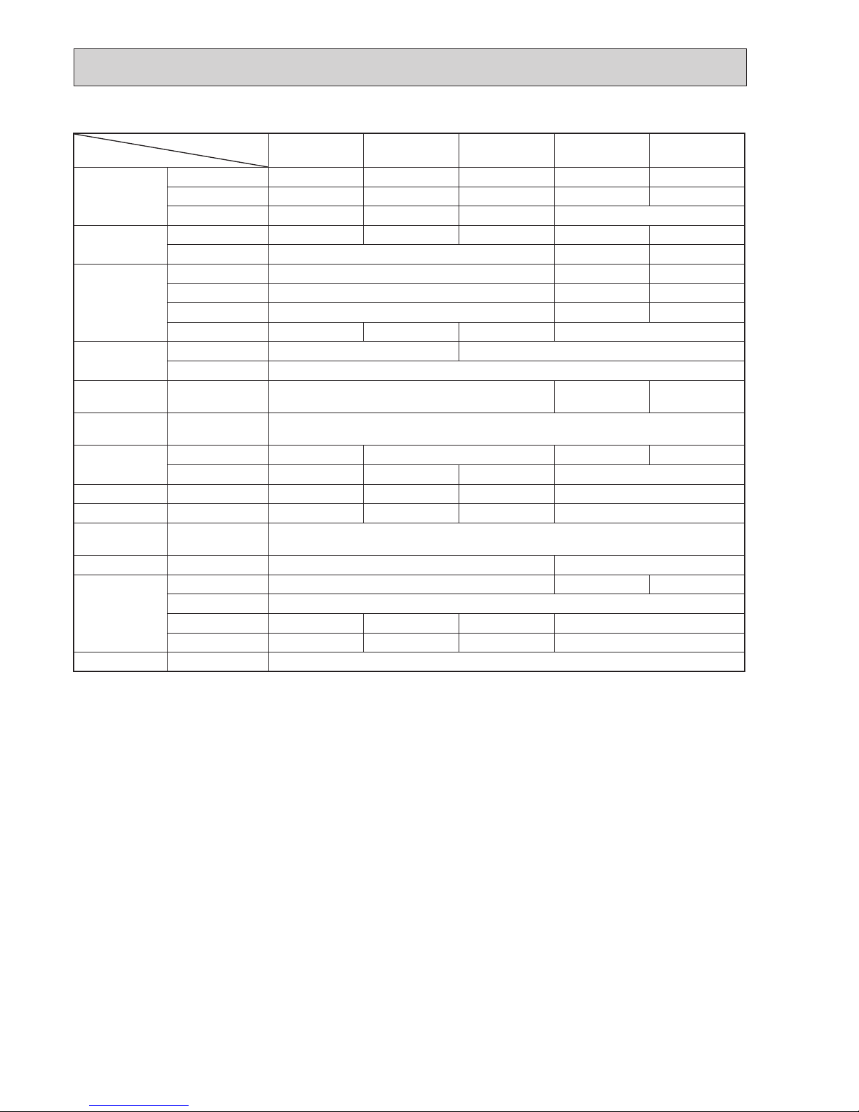
OCH684
Specifications and rating conditions of main electric parts
Model
Item
SUZ-M25VA
(-ET)
SUZ-M35VA
(-ET)
SUZ-M50VA
(-ET)
SUZ-M60VA
(-ET)
SUZ-M71VA
(-ET)
Smoothing
capacitor
(C61) — 620 μF 420 V 620 μF 420 V — —
(C62, C63) 620 μF 420 V 620 μF 420 V 620 μF420 V — —
(CB1, 2, 3) — — — 560 μF 450 V
Diode module
(DB61) 15 A 600 V 15 A 600 V 25 A 600 V — —
(DB65) 25 A 600 V — —
Fuse
(F61) 25 A 250 V — —
(F62) 15 A 250 V — —
(F701, F801, F901)
T3.15 A L250 V — —
(F601, F880, F901)
— — — T3.15 A L250 V
Power module
(IC700) 15 A 600 V 20 A 600 V
(IC932) 5 A 600 V
Switch power
transistor
(Q821) 30 A 600 V — —
Expansion valve
coil
(LEV) 12 V DC
Reactor
(L61) 18 mH 23 mH — —
(L) — — — 282 μH
Diode (D3A, D3B) — — — 20 A 600 V
Diode module (DB41A, DB41B) — — — 20 A 600 V
Current-Limiting
PTC thermistor
(PTC64, PTC65) 33Ω
Terminal block (TB1) 5P 3P
Relay
(X63) 3 A 250 V — —
(X64) 20 A 250 V
(X601) — — — 3 A 250 V
(X602) — — — 3 A 250 V
R.V. coil (21S4) 220–240 V AC
Page 13
13
OCH684
13
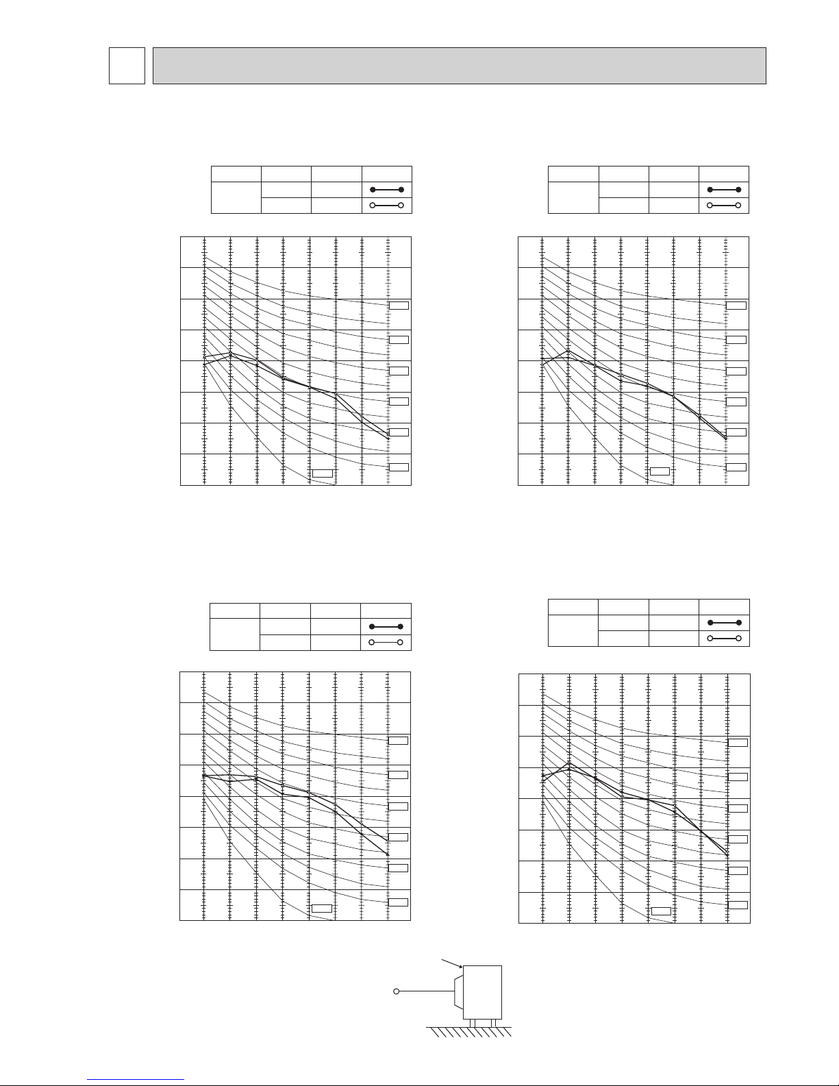
NOISE CRITERIA CURVES
5
OCTAVE BAND SOUND PRESSURE LEVEL, dB re 0.0002 MICRO BAR
COOLING
FUNCTION
SPL(dB(A))
LINE
High
Med.
FAN SPEED
HEATING
45
46
90
80
70
60
50
40
30
20
10
63 125 250 500 1000 2000 4000 8000
NC-60
NC-50
NC-40
NC-30
NC-20
NC-70
BAND CENTER FREQUENCIES, Hz
NC-10
SUZ-M25VA.TH
SUZ-M25VA-ET.TH
OCTAVE BAND SOUND PRESSURE LEVEL, dB re 0.0002 MICRO BAR
COOLING
FUNCTION
SPL(dB(A))
LINE
FAN SPEED
HEATING
48
48
High
Med.
90
80
70
60
50
40
30
20
10
63 125 250 500 1000 2000 4000 8000
NC-60
NC-50
NC-40
NC-30
NC-20
NC-70
BAND CENTER FREQUENCIES, Hz
NC-10
SUZ-M35VA.TH
SUZ-M35VA-ET.TH
COOLING
FUNCTION
SPL(dB(A)) LINE
High
FAN SPEED
HEATING
48
49
OCTAVE BAND SOUND PRESSURE LEVEL, dB re 0.0002 MICRO BAR
90
80
70
60
50
40
30
20
10
63 125 250 500 1000 2000 4000 8000
NC-60
NC-50
NC-40
NC-30
NC-20
NC-70
BAND CENTER FREQUENCIES, Hz
NC-10
SUZ-M50VA.TH
SUZ-M50VA-ET.TH
Test conditions
Cooling: Dry-bulb temperature 35°C
Heating: Dry-bulb temperature 7°C
Wet-bulb temperature 6°C
OUTDOOR UNIT
MICROPHONE
1 m
SUZ-M60VA.TH SUZ-M71VA.TH
SUZ-M60VA-ET.TH SUZ-M71VA-ET.TH
OCTAVE BAND SOUND PRESSURE LEVEL, 0dB re 0.0002 MICRO BAR
COOLING
FUNCTION
SPL(dB(A)) LINE
High
FAN SPEED
HEATING4951
90
80
70
60
50
40
30
20
10
63 125 250 500 1000 2000 4000 8000
NC-60
NC-50
NC-40
NC-30
NC-20
NC-70
BAND CENTER FREQUENCIES, Hz
NC-10
Page 14
14
OCH684
mm (inch)
mm (inch)
6
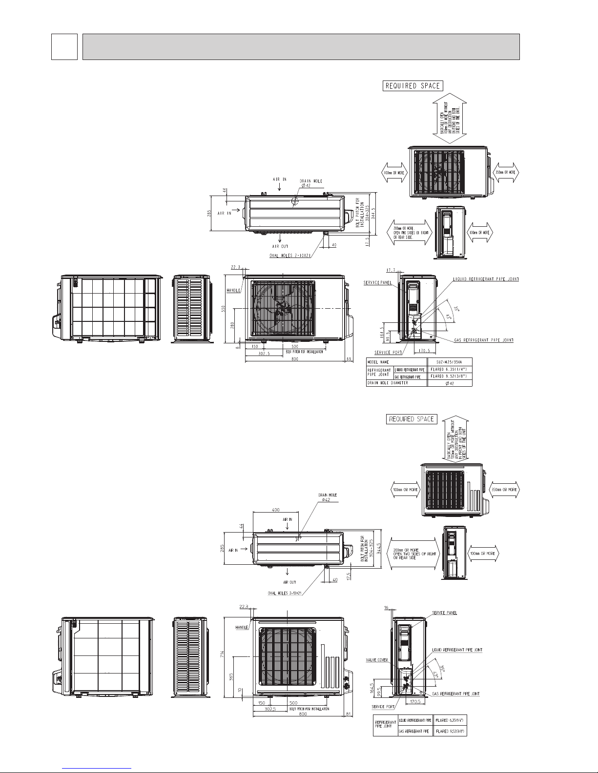
OUTLINES AND DIMENSIONS
Unit: mm
SUZ-M25VA.TH SUZ-M35VA.TH
SUZ-M25VA-ET.TH SUZ-M35VA-ET.TH
Unit: mm
SUZ-M50VA.TH
SUZ-M50VA-ET.TH
Page 15
15
OCH684
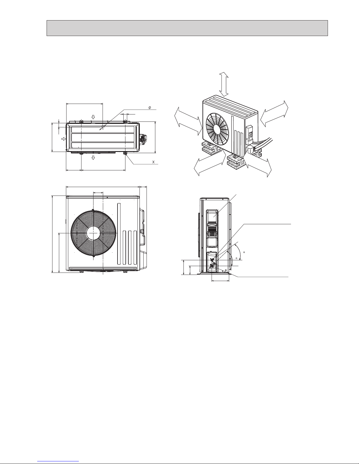
15
SUZ-M60VA.TH SUZ-M71VA.TH
SUZ-M60VA-ET.TH SUZ-M71VA-ET.TH
417.5
40
42
Drain hole
175
500
330
50
Air in
Air out
2-holes 10 21
360
840
109
81
880
452
Service panel
99.5
164.5
195
35
44
Liquid refrigerant pipe joint
Refrigerant pipe (flared)
Ø 6.35
Gas refrigerant pipe joint
Refrigerant pipe (flared)
Ø 12.7
Air in
350 mm or more
100 mm or more
REQUIRED SPACE
100 mm or more
500 mm
or more *2
*1 500 mm or more when front
and sides of the unit are clear
*2 When any 2 sides of left, right
and rear of the unit are clear
Clear *1
Unit: mm
Page 16
16
OCH684
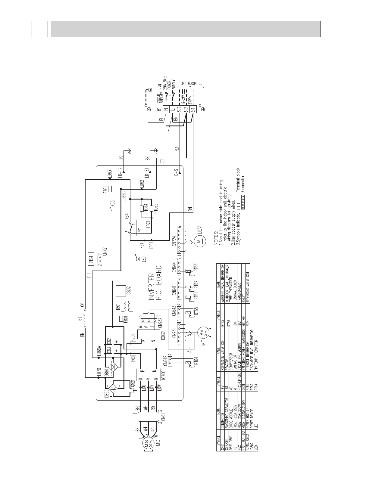
7
WIRING DIAGRAM
SUZ-M25VA.TH
SUZ-M25VA-ET.TH
Page 17

17
OCH684
17
SUZ-M35VA.TH
SUZ-M35VA-ET.TH
Page 18

18
OCH684
SUZ-M50VA.TH
SUZ-M50VA-ET.TH
Page 19

19
OCH684
SUZ-M60VA.TH SUZ-M71VA.TH
SUZ-M60VA-ET.TH SUZ-M71VA-ET.TH
Page 20

20
OCH684
REFRIGERANT SYSTEM DIAGRAM
8
Unit: mm
SUZ-M25VA.TH SUZ-M35VA.TH
SUZ-M25VA-ET.TH SUZ-M35VA-ET.TH
Flared connection
Defrost
thermistor
RT61
Discharge
temperature
thermistor
RT62
Flared connection
Stop valve
(with strainer)
Stop valve
(with service port)
Refrigerant flow in cooling
Compressor
4-way valve
Refrigerant flow in heating
Refrigerant pipe ø9.52
(with heat insulator)
Refrigerant pipe ø6.35
(with heat insulator)
R.V. coil
heating ON
cooling OFF
Strainer
#100
Ambient
temperature
thermistor
RT65
Muffler
Capillary tube
ø3.0×ø2.0×240(M35)
Outdoor heat
exchanger
temperature
thermistor
RT68
Muffler
Outdoor
heat
exchanger
LEV
Strainer
#50
ø4.0×ø2.4×240(M25)
Outdoor
heat
exchanger
Flared connection
Defrost
thermistor
RT61
Discharge
temperature
thermistor
RT62
Flared connection
Stop valve
(with strainer)
Stop valve
(with service port)
Refrigerant flow in cooling
Compressor
4-way valve
Refrigerant flow in heating
Refrigerant pipe ø9.52
(with heat insulator)
Refrigerant pipe ø6.35
(with heat insulator)
R.V. coil
heating ON
cooling OFF
Strainer
#100
Capillary tube
ø3.0×ø2.0×210(×2)
LEV
Ambient
temperature
thermistor
Muffler
Capillary tube
ø4.0×ø2.4×240
Outdoor heat
exchanger
temperature
thermistor
Muffler
RT65
RT68
Strainer
#50
Unit: mm
SUZ-M50VA.TH
SUZ-M50VA-ET.TH
Page 21

21
OCH684
21
Unit: mm
SUZ-M60VA.TH SUZ-M71VA.TH
SUZ-M60VA-ET.TH SUZ-M71VA-ET.TH
Outdoor
heat
exchanger
Flared connection
Defrost
thermistor
RT61
Discharge
temperature
thermistor
RT62
Flared connection
Stop valve
Stop valve
(with service port)
Capillary tube
ø
4.0
×
ø
2.4×100
Refrigerant flow in cooling
Compressor
4-way valve
Refrigerant flow in heating
Refrigerant pipe
ø
15.88
(with heat insulator)
Refrigerant pipe ø6.35
(with heat insulator)
LEV
R.V. coil
heating ON
cooling OFF
Muffler
Strainer
#100
Outdoor heat
exchanger
temperature
thermistor
RT68
Ambient
temperature
thermistor
RT65
Strainer
#100
Strainer
#50
Strainer
#100
Muffler
Capillary tube
ø3.0×ø2.0×200(×6)
Distributer
Page 22

22
OCH684
ADDITIONAL REFRIGERANT CHARGE (R32: g)
MAX. REFRIGERANT PIPING LENGTH
Max. Length
A
* Height difference limitations are binding regardless of the height position at which either indoor or outdoor is placed higher.
* Max. Height
difference
B
Indoor
unit
Outdoor unit
MAX. HEIGHT DIFFERENCE
Calculation : Xg=20g/m×(Refrigerant piping length(m)−7)
Calculation : Xg=55g/m×(Refrigerant piping length(m)−7)
Model
Outdoor unit
precharged
Refrigerant piping length (one way)
7 m 10 m 15 m 20 m
SUZ-M25VA(-ET) 650 0 60 160 260
SUZ-M35VA(-ET) 900 0 60 160 260
Calculation: Xg=30g/m×(Refrigerant piping length(m)−7)
Model
Refrigerant piping: m Piping size O.D: mm
Max. Length A
Max. Height difference B
Gas Liquid
SUZ-M25VA(-ET)
20 12 9.52
6.35
SUZ-M35VA(-ET)
SUZ-M50VA(-ET)
30 30
12.7
SUZ-M60VA(-ET)
15.88
SUZ-M71VA(-ET) 9.52
Model
Outdoor unit
precharged
Refrigerant piping length (one way)
7 m 10 m 15 m 20 m 25 m 30 m
SUZ-M50VA(-ET) 1,200 0 60 160 260 360 460
SUZ-M60VA(-ET) 1,250 0 60 160 260 360 460
Model
Outdoor unit
precharged
Refrigerant piping length (one way)
7 m 10 m 15 m 20 m 25 m 30 m
SUZ-M71VA(-ET) 1,450 0 120 320 520 720 920
Pumping Down
When relocating or disposing of the air conditioner, pump down the system by following the procedure below so that no
refrigerant is released into the atmosphere.
1 Turn off the power supply (circuit breaker).
2 Connect the gauge manifold valve to the service port of the stop valve on the gas pipe side of the outdoor unit.
3 Fully close the stop valve on the liquid pipe side of the outdoor unit.
4 Supply power (circuit breaker).
5 Perform the refrigerant collecting operation (cooling test run).
•
For the PAR-3xMAA ("x" represents 0 or later), select “Service” → “Test Run” from the main menu to start the test run, and then
select the cooling mode.
• For details or for other information about starting the test run when using remote controllers, refer to the installation manual
for the indoor unit or the remote controller.
6 Fully close the stop valve on the gas pipe side of the outdoor unit when the pressure gauge shows 0.05 to 0 MPa [Gauge]
(approx. 0.5 to 0 kgf/cm²) and quickly stop the air conditioner.
• Push the “ON/OFF” button on the remote controller to stop the air conditioner.
Note:
When the extension piping is very long with a large refrigerant amount, it may not be possible to perform a pump down
operation. In this case, use refrigerant recovery equipment to collect all of the refrigerant in the system.
7 Turn off the power supply (circuit breaker), remove the gauge manifold valve, and then disconnect the refrigerant pipes.
.Warning: When pumping down the refrigerant, stop the compressor before disconnecting the refrigerant pipes.
• If the refrigerant pipes are disconnected while the compressor is operating and the stop valve (ball valve) is open,
the pressure in the refrigeration cycle could become extremely high if air is drawn in, causing the pipes to burst,
personal injury, etc.
Page 23

23
OCH684
23
ACTUATOR CONTROL
9
9-3. RELATION BETWEEN MAIN SENSOR AND ACTUATOR
9-2. R.V. COIL CONTROL
Heating
.................
ON
Cooling ................. OFF
Dry
....................
OFF
ON
OFF
ON
OFF
Outdoor fan
Compressor
5 seconds 15 seconds
ON
OFF
Compressor
Outdoor fan
motor
R.V.coil
ON
OFF
ON
OFF
<COOL>
5 seconds
<HEAT>
5 seconds
9-1. OUTDOOR FAN MOTOR CONTROL
The fan motor turns ON/OFF, interlocking with the compressor.
[ON] The fan motor turns ON 5 seconds before the compressor starts up.
[OFF] The fan motor turns OFF 15 seconds after the compressor has stopped running.
NOTE: The 4-way valve reverses for 5 seconds
right before start-up of the compressor.
Sensor Purpose
Actuator
Compressor
LEV
Outdoor fan
motor
R.V.coil
Indoor fan
motor
Discharge temperature
thermistor
Protection
○ ○
Indoor coil temperature
thermistor
Cooling: Coil frost prevention
○
Heating: High pressure protection
○ ○
Defrost thermistor Heating: Defrosting
○ ○ ○ ○ ○
Fin temperature thermistor Protection
○ ○
Ambient temperature
thermistor
Cooling: Low ambient temperature operation
○ ○ ○
Outdoor heat exchanger
temperature thermistor
Cooling: Low ambient temperature operation
○ ○ ○
Cooling: High pressure protection
○ ○ ○
SUZ-M25VA.TH SUZ-M35VA.TH SUZ-M50VA.TH
SUZ-M25VA-ET.TH SUZ-M35VA-ET.TH SUZ-M50VA-ET.TH
SUZ-M60VA.TH SUZ-M71VA.TH
SUZ-M60VA-ET.TH SUZ-M71VA-ET.TH
Page 24

24
OCH684
CHANGE IN DEFROST SETTING
Changing defrost finish temperature
<JS> To change the defrost finish temperature, cut/solder the JS wire of the outdoor inverter P.C. board. (Refer to "11-6-1.
Inverter P.C. board".)
11
TROUBLESHOOTING
3. Troubleshooting procedure
1) Check if the OPERATION INDICATOR lamp on the outdoor P.C. board is blinking on and off to indicate an abnormality. To make sure, check how many times the abnormality indication is blinking on and off before starting service work.
2) Before servicing check that the connector and terminal are connected properly.
3) If the electronic control P.C. board is supposed to be defective, check the copper foil pattern for disconnection and the
components for bursting and discoloration.
4) When troubleshooting, refer to "11-2. TROUBLESHOOTING CHECK TABLE" and "11-3. HOW TO PROCEED "SELFDIAGNOSIS"".
11-1. CAUTIONS ON TROUBLESHOOTING
1. Before troubleshooting, check the following items:
1) Check the power supply voltage.
2) Check the indoor/outdoor connecting wire for miswiring.
2. Take care of the following during servicing.
1)
Before servicing the air conditioner, be sure to turn OFF the main unit first with the remote controller, and turn off the breaker.
2) Be sure to turn OFF the power supply before removing the front panel, the cabinet, the top panel, and the electronic
control P.C. board.
3) When removing the electrical parts, be careful of the residual voltage of smoothing capacitor.
4) When removing the electronic control P.C. board, hold the edge of the board with care NOT to apply stress on the
components.
5) When connecting or disconnecting the connectors, hold the housing of the connector. DO NOT pull the lead wires.
Housing point
Lead wire
10
SERVICE FUNCTIONS
Jumper wire
Defrost nish temperature (°C)
SUZ-M25 SUZ-M35 SUZ-M50
SUZ-M60
SUZ-M71
JS
Soldered (Initial setting) 5 9 9 10
None (cut) 8 13 18 18
SUZ-M25VA.TH SUZ-M35VA.TH SUZ-M50VA.TH
SUZ-M25VA-ET.TH SUZ-M35VA-ET.TH SUZ-M50VA-ET.TH
SUZ-M60VA.TH SUZ-M71VA.TH
SUZ-M60VA-ET.TH SUZ-M71VA-ET.TH
SUZ-M25VA.TH SUZ-M35VA.TH SUZ-M50VA.TH
SUZ-M25VA-ET.TH SUZ-M35VA-ET.TH SUZ-M50VA-ET.TH
SUZ-M60VA.TH SUZ-M71VA.TH
SUZ-M60VA-ET.TH SUZ-M71VA-ET.TH
Page 25

25
OCH684
25
temperature thermistor, outdoor heat exchanger temperature
No. Symptoms
Abnormal point/
Condition
RemedyCondition
1
Outdoor unit
does not operate.
1-time blink
every
2.5 seconds
Outdoor power system
Overcurrent protection cut-out operates 3 consecutive times
within 1 minute after the compressor gets started.
Reconnect connector of compressor.
Refer to 11-5. "How to check inverter/compressor".
Check stop valve.
•
•
•
2
Outdoor thermistors Discharge temperature thermistor shorts, or opens during
compressor running.
defrost thermistor, P.C. board
thermistor or ambient temperature thermistor shorts, or opens
during compressor running.
Refer to 11-5.F"Check of outdoor
thermistors".
•
3
Outdoor control system
Nonvolatile memory data cannot be read properly.
Replace inverter P.C. board. •
4
6-time blink
2.5 seconds
OFF
Serial signal The communication fails between the indoor and outdoor unit
for 3 minutes.
5
11-time blink
2.5 seconds OFF
Stop valve/
Closed valve
Closed valve is detected by compressor current. Check stop valve.
•
6
•
7
'Outdoor unit
stops and
restarts 3
minutes later'
is repeated.
2-time blink
2.5 seconds OFF
Overcurrent protection
Large current flows into intelligent power module.
Reconnect connector of compressor.
Refer to 11-5. "How to check inverter/compressor".
Check stop valve.
•
•
•
8
3-time blink
2.5 seconds OFF
Discharge temperature overheat protection
Temperature of discharge temperature thermistor exceeds
116°C, compressor stops. Compressor can restart if discharge
temperature thermistor reads 100°C or less 3 minutes later.
Check refrigerant circuit and refrigerant amount.
Refer to 11-5. "Check of LEV".
•
•
9
4-time blink
2.5 seconds OFF
Fin temperature
/P.C. board temperature thermistor
overheat protection
Temperature of fin temperature thermistor on the heat sink
exceeds 72 to 86°C or temperature of P.C. board temperature
thermistor on the inverter P.C.board exceeds 72 to 85°C.
Check around outdoor unit.
Check outdoor unit air passage.
Refer to 11-5. "Check of outdoor
fan motor".
•
•
•
10
5-time blink
2.5 seconds OFF
High pressure protection
Indoor coil thermistor exceeds 70°C in HEAT mode. Defrost
thermistor exceeds 70°C in COOL mode.
Check refrigerant circuit and refrigerant amount.
Check stop valve.
•
•
11
8-time blink
2.5 seconds OFF
Compressor synchronous abnormality
The waveform of compressor current is distorted.
Reconnect connector of compressor.
Refer to 11-5. "How to check inverter/compressor".
•
•
12
10-time blink
2.5 seconds OFF
Outdoor fan motor Outdoor fan has stopped 3 times in a row within 30 seconds
after outdoor fan start-up.
Refer to 11-5. "Check of outdoor
fan motor.
Refer to 11-5. "Check of inverter
P.C. board.
•
•
13
12-time blink
2.5 seconds OFF
Each phase current
of compressor
Each phase current of compressor cannot be detected normally.
Refer to 11-5. "How to check inverter/compressor".
•
14
13-time blink
2.5 seconds OFF
DC voltage DC voltage of inverter cannot be detected normally. Refer to 11-5. "How to check in-
verter/compressor".
•
15
Outdoor unit
operates.
1-time blink
2.5 seconds OFF
Frequency drop by
current protection
When the input current exceeds approximately 7A(M25 )/
8A(M35)/12A(M50)14A(M60)/16A(M71), compressor
The unit is normal, but check the
following.
Check if indoor filters are clogged.
Check if refrigerant is short.
Check if indoor/outdoor unit air
circulation is short cycled.
•
•
•
16
3-time blink
2.5 seconds OFF
Frequency drop by
high pressure protection
Temperature of indoor coil thermistor exceeds 55°C in HEAT
mode, compressor frequency lowers.
Frequency drop by
defrosting in COOL
mode
Indoor coil thermistor reads 8°C or less in COOL mode, compressor frequency lowers.
17
4-time blink
2.5 seconds OFF
Frequency drop by
discharge temperature protection
Temperature of discharge temperature thermistor exceeds
111°C, compressor frequency lowers.
Check refrigerant circuit and refrigerant amount.
Refer to 11-5. "Check of LEV".
Refer to 11-5. "Check of outdoor
thermistors".
•
•
•
18
19
7-time blink
2.5 seconds OFF
Low discharge temperature protection
Temperature of discharge temperature thermistor has been
50°C or less for 20 minutes.
Refer to 11-5. "Check of LEV".
Check refrigerant circuit and refrig-
erant amount.
•
•
8-time blink
2.5 seconds OFF
PAM protection
PAM: Pulse Amplitude Modulation
The overcurrent flows into PFC (Power factor correction :
IC820) or the bus-bar voltage reaches 394 V or more, PAM
stops and restarts.
This is not malfunction. PAM protection will be activated in the following cases:
1. Instantaneous power voltage
drop. (Short time power failure)
2. When the power supply voltage
is high.
9-time blink
2.5 seconds OFF
Inverter check mode The connector of compressor is disconnected, inverter check
mode starts.
Check if the connector of the compressor is correctly connected.
Refer to 11-5. "How to check
inverter/compressor".
•
Notes: 1. The location of LED is illustrated at the right figure. Refer to “11-6. Test point diagram and voltage”.
2. LED is lighted during normal operation.
The blinking frequency shows the number of times the LED blinks after every 2.5-second OFF.
(Example) When the blinking frequency is “2”.
ON
OFF
2.5-second OFF
2.5-second OFF
0.5-second ON
0.5-second ON
LED
Blinking →
Inverter P.C. board
•
I
H
H
J
I
F
I
•
Check of indoor/outdoor connecting wire.
Replace indoor or outdoor P.C. board if
abnormality is displayed again.
(M25/35/50)
(M60/71)
Zero cross detecting
circuit
Zero cross signal for PAM control cannot be detected.
LED
indication
check
code
UP
U3
U4
FC
E8
E9
UE
Fin temperature thermistor,
/
frequency lowers.
16-time blink
2.5 seconds
OFF
PL
Outdoor refrigerant
system abnormality
A closed valve and air trapped in the refrigerant circuit are detected
based on the temperature sensed by the indoor and outdoor thermistors
and the current of the compressor.
•
Check for a gas leak in a connecting
piping, etc.
Check stop valve.
•
Refer to 11-5
.
L
refrigerant circuit”.
•
"Check of outdoor
20
11-2. TROUBLESHOOTING CHECK TABLE
Page 26

26
OCH684
F1 F2 F3 F4
unem ecivreS
rosruC
:unem niaM
Test run
Input maintenance info.
Function setting
Check
Self check
kcehc fleS
:tceleS
Ref. address
sserddA
kcehc fleS
Ref. address
Return:
teseR
Error Unt # CI.prG
Self check
Return:
Reset
Ref. address
Error
--
Unt #
Grp.
-- --
When there is no error history
Self check
Delete error history?
Ref. address
Cancel OK
Self check
Return:
Ref. address
Error history deleted
2
With theF1orF2button, enter the refrigerant address, and press the button.
Select "Self check" with the F1 or F2 button, and press the button.
1
Select "Service" from the Main menu, and press the button.
3
Check code, unit number, attribute will appear.
"-" will appear if no error history is available.
4
Resetting the error history.
Press the
F4
button (Reset) on the screen that shows the error history.
A conrmation screen will appear asking if you want to delete the error history.
Press the
F4
button (OK) to delete the error history.
If deletion fails, "Request rejected" will appear.
"Unit not exist" will appear if no indoor units that are correspond to the entered
address are found.
Navigating through the screens
• To go back to the Service menu ..........
button
• To return to the previous screen .......
button
11-3. HOW TO PROCEED "SELF-DIAGNOSIS"
11-3-1. Self-diagnosis <PAR-3xMAA ("x" represents 0 or later)>
As this air conditioner has a function to memorize all the failures that had occured, the latest failure detail can be recalled by
following the procedure below.
Use this function when the check code is not displayed with wired remote controller or the remote controller at use is wireless
type.
Page 27

27
OCH684
If operations cannot be completed with the remote controller, diagnose the remote controller with this function.
F1 F2 F3 F4
unem ecivreS
rosruC
:unem niaM
Maintenance password
Remote controller check
F1 F2 F3 F4
Remote controller check
:nigeB
Start checking?
Remote controller check
:nigeB
Start checking?
1
Select "Service" from the Main menu, and press the button.
Select "Remote controller check" with the F1
or F2 button, and press
the
button.
2
Select "Remote controller check" from the Service menu, and press the button to start the remote controller check and see the check results.
To cancel the remote controller check and exit the Remote controller check
menu screen, press the
or the button.
The remote controller will not reboot itself.
Check the remote controller display and see if anything is displayed
(including lines). Nothing will appear on the remote controller display if
the correct voltage (8.5–2 V DC) is not supplied to the remote controller.
If this is the case, check the remote controller wiring and indoor units.
OK: No problems are found with the remote controller. Check other
parts for problems.
E3, 6832: There is noise on the transmission line, or the indoor unit or another
remote controller is faulty. Check the transmission line and the
other remote controllers.
NG (ALL0, ALL1):
Send-receive circuit fault. Remote controller needs replacing.
ERC:
The number of data errors is the discrepancy between the number of
bits in the data transmitted from the remote controller and that of the
data that was actually transmitted over the transmission line. If data
errors are found, check the transmission line for external noise inter
-
ference.
Remote controller check results screen
If the button is pressed after the remote controller check results are displayed, remote controller check will end, and the remote controller will automati-
cally reboot itself.
11-3-2. Remote controller check <PAR-3xMAA ("x" represents 0 or later)>
3
Page 28

28
OCH684
11-3-3. Self-diagnosis <PAC-YT52CRA>
Retrieve the error history of each unit using the Simple MA controller.
1 Switch to the self-diagnosis mode.
When the A button and the button are pressed for 5 seconds or longer, the
figure shown below is
2
Set the address or refrigerant address No. you want to self-diagnosis.
When the
B
and
C
are pressed, the address decreases and increases between 01 and 50 or 00 and 15.
Set it to the address No. or refrigerant address No. you want to self-diagnosis.
ON
OFF
.
. .
C
Self-diagnosis address
or self-diagnosis
refrigerant address
Approximately 3 seconds
after the change operation, the
self-diagnosis refrigerant
address changes from blinking
to a steady light and selfdiagnosis begins.
3
Self-diagnosis result display <error history>
the contents of the check code, refer to the indoor unit installation
Check code 4 digits or
check code 2 digits
Error detection attribute
Address 3 digits or
unit address No. 2 digits
<When there is no error history> <When opposite side does not exist>
(Alternate
display)
4
Error history reset
The error history is displayed in 3 self-diagnosis results display.
When the
D button is pressed 2 times successively within 3 seconds, the self-diagnosis object address
When the error history was reset, the display shown below appears.
When error history reset is failed, the error contents are displayed again.
5
Self-diagnosis reset
There are the following 2 ways of resetting self-diagnosis.
Press the
A button and the C button simultaneously for 5 seconds or longer.
→
Resets self-diagnosis and returns to the state before self-diagnosis.
Press the
A
button. → Self-diagnosis resets and indoor units stop.
prohibited, this operation is ineffective.)
ON
OFF
.
ON
OFF
displayed.
manual or service handbook.)
and refrigerant address blink.
(For
(When operation is
Page 29

29
OCH684
11-3-4. Remote Controller Check <PAC-YT52CRA>
When the air conditioner cannot be controlled from the Simple MA controller, use this function
to check the remote controller.
1
First, check the power mark.
When normal voltage (12 V DC) is not applied to the remote controller, the power mark goes off.
When the power mark is off, check the remote controller wiring and the indoor unit.
2
Switch to the remote controller check mode.
When the B
button and
D
button are pressed simultaneously for 5 seconds or
longer, the figure
When the
A
button is pressed, remote controller check begins.
.
ON
OFF
Remote controller check result
<When remote controller is normal>
3
Since there is no problem at the remote controller, check for other causes.
<When remote controller is faulty>
(Error display 1) “NG” blinks →
Remote controller sends/receives circuit abnormal
Remote controller switching is necessary.
When the problem is other than the checked remote controller
(Error display 2) “E3” “6833” “6832” blink
→
Cannot send
(Error display 3) “ERC” and data error count are displayed
→
Data error generation
There is noise on the transmission line, or the indoor unit or another remote controller is faulty.
Check the transmission line and the other remote controllers.
“Data error count” is the difference between the number of bits of remote controller send
data and the number of bits actually sent to the transmission line. In this case, the
send
data was disturbed by the noise, etc. Check the transmission line.
When data error count is 02
Remote controller send data
Send data on transmission line
4
Remote controller check reset
When the
B
button and
D
button are pressed simultaneously for 5 seconds or
longer, remote controller
and run lamp blink for a certain period of time, and then the remote controller returns to its
.
diagnosis is
reset, the [HO]
shown below is displayed.
Power mark
state before diagnosis.
Page 30

30
OCH684
[Procedure]
1. Press the CHECK button twice.
• "CHECK" lights, and refrigerant address "00" blinks.
• Check that the remote controller's display has stopped before continuing.
2. Press the TEMP buttons.
• Select the refrigerant address of the indoor unit for the self-diagnosis.
Note: Set refrigerant address using the outdoor unit’s DIP switch (SW1).
(For more information, see the outdoor unit installation manual.)
3. Point the remote controller at the sensor on the indoor unit and press the
HOUR button.
• If an air conditioner error occurs, the indoor unit's sensor emits an
intermittent buzzer sound, the operation light blinks, and the check
code is output.
(It takes 3 seconds at most for check code to appear.)
4. Point the remote controller at the sensor on the indoor unit and press the
ON/OFF button.
• The check mode is cancelled.
<Malfunction-diagnosis method at maintenance service>
11-3-5. Self-diagnosis <Wireless remote controller> *
For SLZ model, refer to the indoor unit's service manual.
<In case of trouble during operation, except for SLZ model*>
When a malfunction occurs to air conditioner, both indoor unit and outdoor unit will stop and operation lamp blinks to inform
unusual stop.
ON/OFF
TEMP
FAN
VANE
MODE
CHECK
LOUVER
TEST RUN
AUTO STOP
AUTO START
h
min
RESET
SET
CLOCK
CHECK
CHECK
display
TEMP
button
CHECK
button
Refrigerant
address
display
HOUR
button
ON/OFF
button
Page 31

31
OCH684
OPERATION
INDICATOR
lamp blink
pattern
Beep Beep Beep Beep Beep
Beep Beep
Off
Approx. 2.5 sOnApprox. 3 sOn0.5 sOn0.5 sOn0.5 s
On
0.5 s
Off
Approx. 2.5 sOnApprox. 3 sOn0.5 sOn0.5 s
··· Repeated
Number of blinks/beeps in pattern indicates the check
code in the following table (i.e., n=5 for “U2”)
Number of blinks/beeps in pattern indicates
the check code in the following table
n
th
1st2nd3
rd
1st2
nd
Self-check
starts
(Start signal
received)
Beeper sounds
[Output pattern B]
OPERATION
INDICATOR
lamp blink
pattern
Beep
Beep Beep Beep Beep Beep Beep
Off
Approx. 2.5 s
On
0.5 sOn0.5 sOn0.5 s
On
0.5 s
Off
Approx. 2.5 sOn0.5 sOn0.5 s
··· Repeated
Number of blinks/beeps in pattern indicates the check
code in the following table (i.e., n=5 for “P5”)
Number of blinks/beeps in pattern indicates
the check code in the following table
n
th
1st2nd3
rd
1st2
nd
Self-check
starts
(Start signal
received)
Beeper sounds
• Refer to the following tables for details on the check codes.
[Output pattern A]
[Output pattern A] Errors detected by indoor unit
Wireless remote controller
Wired remote controller
Symptom Remark
Beeper sounds/OPERATION
INDICATOR lamp blinks
(Number of times)
Check code
1 P1 Intake sensor error
As for indoor
unit, refer to
indoor unit's
service manual.
2
P2 Pipe (TH2) sensor error
P9 Pipe (TH5) sensor error
3 E6,E7 Indoor/outdoor unit communication error
4 P4 Drain sensor error/Float switch connector (CN4F) open
5
P5 Drain pump error
PA Forced compressor stop (due to water leakage abnormality)
6 P6 Freezing/Overheating protection operation
7 EE Communication error between indoor and outdoor units
9 E4,E5 Remote controller signal receiving error
12 Fb (FB)* Indoor unit control system error (memory error, etc.)
14 PL Abnormality of refrigerant circuit
- E0,E3 Remote controller transmission error
- E1,E2 Remote controller control board error
[Output pattern B] Errors detected by unit other than indoor unit (outdoor unit, etc.)
Wireless remote controller
Wired remote controller
Symptom
Beeper sounds/OPERATION
INDICATOR lamp blinks
(Number of times)
Check code
1 E9
Indoor/outdoor unit communication error
(Transmitting error) (Outdoor unit)
2 UP Compressor overcurrent interruption
3 U3,U4 Open/short of outdoor unit thermistors
14 PL or Others
Abnormality of refrigerant circuit or other errors
(Refer to the technical manual for the outdoor unit.)
Notes: 1. If the beeper does not sound again after the initial 2 beeps to conrm the self-check start signal was received and
the OPERATION INDICATOR lamp does not come on, there are no error records.
2. If the beeper sounds 3 times continuously “beep, beep, beep (0.4 + 0.4 + 0.4 sec.)” after the initial 2 beeps to
conrm the self-check start signal was received, the specied refrigerant address is incorrect.
*The check code in the parenthesis indicates PAR-3xMAA model.("x" represents 0 or later).
Page 32

32
OCH684
11-4. TROUBLE CRITERION OF MAIN PARTS
Parts name
Figure
Check method and criterion
Outdoor fan motor
R.V. coil (21S4)
Expansion valve coil
(LEV)
Measure the resistance between terminals with a tester.
(Temperature: −10 to 40°C)
WH - BK
BK - RD
RD - WH
Normal
Measure the resistance between terminals with a tester.
(Temperature : −10 to 40°C)
Normal
Measure the resistance with a tester.
Refer to “11-6. Test point diagram and voltage”, 11-6-1. (M25/35/50) or
11-6-2. (M60/71) “Inverter P.C. board”, for the chart of thermistor.
Color of the lead wire
Discharge temperature
thermistor (RT62)
Measure the resistance with a tester.
Before measurement, hold the thermistor with your hands to warm it up.
Refer to “11-6. Test point diagram and voltage”, 11-6-1. (M25/35/50) or
11-6-2. (M60/71) “Inverter P.C. board”, for the chart of thermistor.
Defrost thermistor (RT61)
Fin temperature
thermistor (RT64)
32 to 43 Ω
Measure the resistance between terminals with a tester.
(Temperature: −10 to 40°C)
Compressor
U-V
U-W
V-W
Normal
W
U
V
WH
RD BK
W
U
V
WH
RD BK
Ambient temperature
thermistor (RT65)
Outdoor heat exchanger
temperature thermistor(RT68)
SUZ-M25
1.59 to 2.16Ω
SUZ-M35
1.60 to 2.17 Ω
1.41 to 2.00 kΩ
SUZ-M50/60
0.82 to 1.11 Ω
SUZ-M71
0.87 to 1.18 Ω
SUZ-M25/35 SUZ-M50
15 to 20 Ω
LEV
WH
RD
YE
OG
BU
Measure the resistance with a tester.
(Temperature : −10 to 40°C)
RD - OG
RD - WH
RD - BU
RD - YE
Normal
37 to 54 Ω
Color of the lead wire
SUZ-M60/71
25 to 34 Ω
1.17 to 1.66 kΩ
SUZ-M25/35/50 SUZ-M60/71
SUZ-M25VA.TH SUZ-M35VA.TH SUZ-M50VA.TH
SUZ-M25VA-ET.TH SUZ-M35VA-ET.TH SUZ-M50VA-ET.TH
SUZ-M60VA.TH SUZ-M71VA.TH
SUZ-M60VA-ET.TH SUZ-M71VA-ET.TH
Page 33

33
OCH684
A How to check inverter/compressor
Are the voltages balanced?
Disconnect the connector between the
compressor and the intelligent power module
(IC700)
.
Replace the inverter P.C. board.
Check the voltage between terminals.
Check the compressor.
See 11-5. “Check of compressor”.
No
Yes
See 11-5. “Check of open phase”.
With the connector between the compressor and the intelligent power module disconnected, activate the inverter and check if
the inverter is normal by measuring the voltage balance between the terminals.
Output voltage is 50–130 V. (The voltage may differ according to the tester.)
< Operation method (Test run operation)>
• For the
PAR-3xMAA model.("x" represents 0 or later), select “Service” → “Test Run” from the main menu to start the test
run, and then select the cooling mode.
• For details or for other information about starting the test run when using remote controllers, refer to the installation manual
for the indoor unit or the remote controller.
<Measurement point>
At 3 points
BK (U) - WH (V)
BK (U) - RD (W)
WH (V) - RD (W)
NOTE: 1. Output voltage varies according to power supply voltage.
2. Measure the voltage by analog type tester.
3. During this check, LED of the inverter P.C. board blinks 9 times. (M25/35/50: Refer to 11-6-1, M60/71: 11-6-2)
Refer to 11-5. “Check of compressor
operation time”.
Does the compressor operate continuously?
OK
No
Yes
Refer to 11-5. “Check of compressor
winding”.
Is the compressor normal?
Replace the compressor.
No
Yes
C Check of compressor
B Check of open phase
11-5. TROUBLESHOOTING FLOW
Measure AC voltage between the lead wires at 3 points.
Is the compressor
operation time more than
10 seconds?
Replace the compressor.
No
Yes
Check the refrigerant circuit.
Page 34

34
OCH684
D Check of compressor winding
Disconnect the connector between the compressor and the intelligent power module, and measure the resistance between the
compressor terminals.
<Measurement point>
Measure the resistance between the lead wires at 3 points.
BK-WH
BK-RD
WH-RD
<Judgement>
Refer to "11-4. TROUBLE CRITERION OF MAIN PARTS".
0 [Ω] ················Abnormal [short]
Infinite [Ω] ·······Abnormal [open]
NOTE: Be sure to zero the ohmmeter before measurement.
E Check of compressor operation time
Compressor starts
Abnormal
(IPM failure)
(Compressor winding short)
Abnormal
(Compressor lock out)
(Starting defect)
Abnormal
(Poor contact,)
(Outdoor P.C. board defect)
(Disconnected connector)
Abnormal
(Refrigerant circuit defect)
(Closed valve)
Normal
0 second
1 second
2 seconds
10 seconds
10 minutes
<<Judgement>>
Connect the compressor and activate the inverter. Then measure the
time until the inverter stops due to overcurrent.
<Operation method>
Start heating or cooling test run.
(TEST RUN OPERATION : Refer to 11-5
.)
<Measurement>
Measure the time from the start of compressor to the stop of
compressor due to overcurrent.
Is the resistance of thermistor normal?
(M25/35/50: Refer to 11-6-1,M60/71: 11-6-2.)
Disconnect the connector of thermistor in the outdoor P.C. board (see
below table), and measure the resistance of thermistor.
Replace the thermistor except RT64.
When RT64 is abnormal, replace the inverter
P.C. board.
Reconnect the connector of thermistor.
Turn ON the power supply and press EMERGENCY OPERATION switch.
No
Yes
F Check of outdoor thermistors
Does the unit operate for 10 minutes or more
without showing thermistor abnormality?
Yes
OK
(Cause is poor contact.)
No
Replace the inverter P.C. board.
Thermistor Symbol
Connector, Pin No.
Board
SUZ-M25/35/50 SUZ-M60/71
Defrost RT61 Between CN641 pin1 and pin2 Between CN671 pin1 and pin2
Inverter
P.C. board
Discharge temperature RT62 Between CN641 pin3 and pin4 Between CN671 pin3 and pin4
Fin temperature RT64 Between CN642 pin1 and pin2 Between CN673 pin1 and pin2
Ambient temperature RT65 Between CN643 pin1 and pin2 Between CN672 pin1 and pin2
Outdoor heat exchanger temperature RT68 Between CN644 pin1 and pin3 Between CN671 pin5 and pin6
Page 35

35
OCH684
G Check of R.V. coil
First of all, measure the resistance of R.V. coil to check if the coil is defective. Refer to "11-4. TROUBLE CRITERION OF
MAIN PARTS".
In case CN721(M25/35/50)/CN602(M60/71) is not connected or R.V. coil is open, voltage is generated between the
terminal pins of the connector although any signal is not being transmitted to R.V. coil.
Check if CN721(M25/35/50)/CN602(M60/71) is connected.
Is there 230 VAC between CN721
(M25/35/50)/CN602(M60/71)
and on
the inverter P.C. board 3 minutes after the
power supply is turned ON?
No
Yes
Replace the inverter
P.C. board.
Replace the 4-way valve.
Unit operates COOL mode even if it is set to HEAT mode.
Is there 230 VAC between CN721
(M25/35/50)/CN602(M60/71)
and on
the inverter P.C. board 3 minutes after the
power supply is turned ON?
Yes
No
Replace the inverter
P.C. board.
Replace the 4-way valve.
Unit operates HEAT mode even if it is set to COOL mode.
Disconnect connector between
the compressor and the intelligent
power module.
Turn ON the power supply and start
heating test run.
(TEST RUN OPERATION: Refer to
11-5
)
Disconnect connector between
the compressor and the intelligent
power module.
Turn ON the power supply and start
cooling test run.
(TEST RUN OPERATION: Refer to
11-5
)
H Check of outdoor fan motor
Is the resistance between each terminal of outdoor fan motor normal? (Refer to "11- 4. TROUBLE CRITERION
OF MAIN PARTS". )
Disconnect the connectors CN931
and CN932 from the inverter P.C.
board. Check the connection between
the connector CN931 and CN932.
Disconnect CN932 from the inverter
P.C. board, and turn on the power sup-
ply.
Rotate the outdoor fan motor manually and measure the voltage of CN931.
Between 1(+) and 5(−)
Between 2(+) and 5(−)
Between 3(+) and 5(−)
Does the voltage between each terminal become 5 and 0 V
DC repeatedly?
Does the outdoor fan motor rotate smoothly?
Replace the outdoor fan motor.
Replace the inverter P.C. board.
Yes
Yes
No
(Fixed to either 5 or 0 V DC)
No
No
Yes
Page 36

36
OCH684
I Check of LEV
Turn on power supply to the outdoor unit after checking
LEV coil is xed to the LEV body securely.
Yes
Disconnect the connector CN724 is there normal resistance to LEV coil?
No
Replace the inverter P.C. board.
Replace the LEV coil.
No
Normal
Start
Is "click - click" sound heard?
Or, do you feel vibration of the LEV coil with a hand?
Yes
Check the outdoor fan motor.
(Refer to .)
Is the fuse (F901) blown on the inverter P.C. board?
Check the connection of the connectors
(CN931, CN932) of the outdoor fan motor.
If the connection is poor, correct it.
Operate the outdoor unit by starting
EMERGENCY OPERATION.
Check the LED indication on the inverter P.C. board.
Does the LED blink 10 times?
Replace the inverter P.C. board.
Check the corresponding parts
following LED indication.
(Refer to "11-3. HOW TO PROCEED "SELF-DIAGNOSIS"".)
Yes
No
Yes
(10-time blink)
No
J Check of inverter P.C. board
Page 37

37
OCH684
Electromagnetic noise enters into TV sets or radios
Yes
Is the unit earthed?
No
Earth the unit.
Yes
Is the distance between the antennas
and the indoor unit within 3 m, or is the
distance between the antennas and the
outdoor unit within 3 m?
No
Extend the distance between the antennas and
the indoor unit, and/or the antennas and the
outdoor unit.
Is the distance between the TV sets or
radios and the indoor unit within 1 m, or
is the distance between the TV sets or
radios and the outdoor unit within 3 m?
Yes
Extend the distance between the TV sets and/or
radios and the indoor unit, or the TV sets or
radios and the outdoor unit.
Are the antennas damaged?
Is the coaxial cable damaged?
Is there any poor contact in the antenna wiring?
Yes
No
No
Replace or repair the antenna.
Replace or repair the coaxial cable.
Is the indoor/outdoor connecting wire
of the air conditioner and the wiring of
the antennas close?
Yes
Extend the distance between the indoor/outdoor
connecting wire of the air conditioner and the wiring of the antennas.
No
Even if all of the above conditions are fullled, the electromagnetic noise may enter, depending on the electric eld strength
or the installation condition (combination of specic conditions such as antennas or wiring).
Check the following before asking for service.
1. Devices affected by the electromagnetic noise
TV sets, radios (FM/AM broadcast, shortwave)
2. Channel, frequency, broadcast station affected by the electromagnetic noise
3. Channel, frequency, broadcast station unaffected by the electromagnetic noise
4. Layout of ;
indoor/outdoor unit of the air conditioner, indoor/outdoor wiring, earth wire, antennas, wiring from antennas, receiver
5. Electric eld intensity of the broadcast station affected by the electromagnetic noise
6. Presence or absence of amplier such as booster
7. Operation condition of air conditioner when the electromagnetic noise enters in
1) Turn OFF the power supply once, and then turn ON the power supply. In this situation, check for the electromagnetic
noise.
2) Within 3 minutes after turning ON the power supply, press OPERATE/STOP (ON/OFF) button on the remote controller
for power ON, and check for the electromagnetic noise.
3) After a short time (3 minutes later after turning ON), the outdoor unit starts running. During operation, check for the
electromagnetic noise.
4) Press OPERATE/STOP (ON/OFF) button on the remote controller for power OFF, when the outdoor unit stops but the
indoor/outdoor communication still runs on. In this situation, check for the electromagnetic noise.
K
Page 38

38
OCH684
Check of outdoor refrigerant circuit
L
The unit occasionally stops when the
stop valve is opened or closed during
operation. Open the stop valve and
start the cooling operation again.
No
Has the operation stopped
during pump down?
Yes
Was the operation started with
the stop valve closed, and was
it opened during operation?
Yes
The refrigerant gas amount may
be 60% or less than the normal
amount. Identify where the gas is
leaking from, and x the leak.
No
CAUTION:
Do not start the operation again to
prevent hazards.
The operation has stopped to
prevent the diesel explosion caused
by air trapped in the refrigerant
circuit. Close the stop valve, and
disconnect the power plug or turn
the breaker OFF.
Note: If the abnormality can not be reset with remote controllers, it is
detected in the connected indoor unit. Please refer to the indoor
unit's service manual.
Page 39

39
OCH684
11-6. TEST POINT DIAGRAM AND VOLTAGE
11-6-1. Inverter P.C. board
SUZ-M25VA.TH SUZ-M35VA.TH SUZ-M50VA.TH
SUZ-M25VA-ET.TH SUZ-M35VA-ET.TH SUZ-M50VA-ET.TH
-20 -10 0 10 20 30 40
0
10
20
30
40
50
60
70
80
90
100
Temperature( )
Defrost thermistor(RT61)
Ambient temperature thermistor(RT65)
Outdoor heat exchanger temperature thermistor(RT68)
0 10 20 30 40 50 60 70 80
0
20
40
60
80
100
120
140
160
180
200
Temperature( )
Fin temperature thermistor(RT64)
Resistance(k )
Resistance(k )
Temperature (°C)
Discharge temperature thermistor (RT62)
Resistance (kΩ)
0
100
200
300
400
500
600
700
800
0 10 20 30 40 50 60 70 8 0 90 10 01 10 120
Fin temperature
thermistor/RT64
(CN642)
Ambient temperature
thermistor/RT65
(CN643)
Discharge temperature
thermistor/RT62
(CN641)
Defrost thermistor
/RT61(CN641)
DB61
260 - 370 V DC
Front side of unit
230 V AC
Output to
drive
compressor
(LDU,
LDV,
LDW)
(+)
(-)
Fuse (F701)
T3.15AL250V
R.V.coil
(CN721)
230 V AC
Jumper wire for
changing defrost
setting (JS)
Signal of outdoor
fan motor (CN931)
230 V AC
Outdoor heat exchanger
temperature thermistor
/RT68 (CN644)
Jumper wire
for pre-heat
control setting
(JK)
Fuse (F801)
T3.15AL250V
Back side of unit
LEV (CN724)
Output to
drive outdoor
fan motor
(CN932)
LED
Defrost heater
(CN722)
Fuse (F62)
15 A 250 V
Fuse (F901)
T3.15AL250V
Smoothing
capacitor
(C63)
Smoothing
capacitor
(C62)
Smoothing
capacitor (C61)
(SUZ-M35/50)
Fuse (F61)
25 A 250V
Page 40

40
OCH684
11-6-2. Inverter P.C. board
SUZ-M60VA.TH SUZ-M71VA.TH
SUZ-M60VA-ET.TH SUZ-M71VA-ET.TH
−20 −10 0 10 20 30 40
0
10
20
30
40
50
60
70
80
90
100
Temperature( )
Defrost thermistor(RT61)
Ambient temperature thermistor(RT65)
Outdoor heat exchanger temperature thermistor(RT68)
Temperature( )
Discharge temperature thermistor(RT62)
0 10 20 30 40 50 60 70 80 90 100 11 0 120
0
100
200
300
400
500
600
700
0 10 20 30 40 50 60 70 80
0
20
40
60
80
100
120
140
160
180
200
Temperature( )
Fin temperature thermistor(RT64)
Resistance(k )
Resistance(k )
Resistance(k )
Fin temperature
thermistor/RT64
(CN673)
Ambient temperature
thermistor/RT65
(CN672)
Discharge temperature
thermistor/RT62
(CN671)
Defrost thermistor
/RT61 (CN671)
Output to
drive outdoor
fan motor
(CN932)
Outdoor heat exchanger
temperature thermistor
/RT68 (CN671)
Fuse (F901)
T3.15AL250V
Fuse (F880)
T3.15AL250V
LEV (CN724)
Jumper wire for
changing defrost
setting (JS)
Jumper wire for
pre-heat control
setting (JK)
Fuse (F601)
T3.15AL250V
Signal of outdoor fan motor
(CN931)
R.V. coil (CN602)
230 V AC
230 V AC
260 - 370 V DC
IC700 (N)
IC700 (P)
LED
Page 41

41
OCH684
41
12
DISASSEMBLY PROCEDURE
(1) Slide the sleeve and check if there is a locking lever or not. (2) The terminal with this connector has the
locking mechanism.
1Slide the sleeve.
2Pull the terminal while
pushing the locking
lever.
1Hold the sleeve, and
pull out the terminal
slowly.
The terminal which has the locking mechanism can be detached as shown below.
There are 2 types (Refer to (1) and (2)) of the terminal with locking mechanism.
The terminal without locking mechanism can be detached by pulling it out.
Check the shape of the terminal before detaching.
<"Terminal with locking mechanism" Detaching points>
Connector
Sleeve
Locking lever
SUZ-M25VA.TH SUZ-M35VA.TH
SUZ-M25VA-ET.TH SUZ-M35VA-ET.TH
: Indicates the visible parts in the photos/gures.
: Indicates the invisible parts in the photos/gures.
NOTE: Turn OFF the power supply before disassembly.
OPERATING PROCEDURE PHOTOS/FIGURES
1. Removing the cabinet
(1) Remove the screw fixing the service panel.
(2) Pull down the service panel and remove it.
(3) Disconnect the power supply cord and indoor/outdoor
connecting wire.
(4) Remove the screws fixing the top panel.
(5) Remove the top panel.
(6) Remove the screws fixing the cabinet.
(7) Remove the cabinet.
(8) Remove the screws fixing the back panel.
(9) Remove the back panel.
Photo 3
Photo 1
Photo 2
Back panel
Service panel
Screws of the top panel
Screws of the terminal block support and the back panel
Screws of the cabinet
Screws of
the back panel
Screws of
the top panel
Direction to
remove
Screws of the cabinet
Hooks of
the service
panel
Screw of the cabinet
Screw of
the service
panel
Page 42

42
OCH684
OPERATING PROCEDURE
PHOTOS/FIGURES
2. Removing the inverter assembly, inverter P.C. board
(1) Remove the cabinet and panels. (Refer to section 1.)
(2) Disconnect the lead wire to the reactor and the following con-
nectors:
<Inverter P.C. board>
CN721 (R.V. coil)
CN931, CN932 (Fan motor)
CN641 (Defrost thermistor and discharge temperature ther-
mistor)
CN643 (Ambient temperature thermistor)
CN644 (Outdoor heat exchanger temperature thermistor)
CN724 (LEV)
(3) Remove the compressor connector (CN61).
(4) Remove the screws fixing the heat sink support and the sep-
arator.
(5) Remove the fixing screws of the terminal block support and
the back panel.
(6) Remove the inverter assembly.
(7) Remove the screw of the earth wire and screw of the termi-
nal block support.
(8) Remove the heat sink support from the P.C. board support.
(9) Remove the screw of the inverter P.C. board and remove the
inverter P.C. board from the P.C. board support.
Photo 4
Photo 5 (Inverter assembly)
Photo 6
3. Removing R.V. coil
(1) Remove the cabinet and panels. (Refer to section 1.)
(2) Disconnect the following connectors:
<Inverter P.C. board>
CN721 (R.V. coil)
(3) Remove the R.V. coil.
4. Removing the discharge temperature thermistor,
defrost thermistor, outdoor heat exchanger temperature thermistor and ambient temperature thermistor
(1) Remove the cabinet and panels. (Refer to section 1.)
(2) Disconnect the lead wire to the reactor and the following con-
nectors:
<Inverter P.C. board>
CN641 (Defrost thermistor and discharge temperature ther-
mistor)
CN643 (Ambient temperature thermistor)
CN644 (Outdoor heat exchanger temperature thermistor)
(3) Pull out the discharge temperature thermistor from its holder.
(4) Pull out the defrost thermistor from its holder. (Photo 7)
(5) Pull out the outdoor heat exchanger temperature thermistor
from its holder. (Photo 7)
(6) Pull out the ambient temperature thermistor from its holder.
Discharge temperature thermistor
Screw of the
R.V. coil
Screws of the heat sink
support and the separator
Screws of the terminal block
support and the back panel
Heat sink
Screw of the
earth wire
Screw of the
Terminal block
support
Screw of the
inverter P.C. board
Heat sink support
P.C. board
support
Terminal
block
support
Page 43

43
OCH684
OPERATING PROCEDURE
PHOTOS/FIGURES
5. Removing outdoor fan motor
(1) Remove the cabinet and panels. (Refer to section 1.)
(2) Disconnect the following connectors:
<Inverter P.C. board>
CN931, CN932 (Fan motor)
(3) Remove the propeller fan nut.
(4) Remove the propeller fan.
(5) Remove the screws fixing the fan motor.
(6) Remove the fan motor.
Photo 7
NOTE: SUZ-M25/35VA are different in the installation
position of thermistors.
Photo 8
6. Removing the compressor and 4-way valve
(1) Remove the cabinet and panels. (Refer to section 1.)
(2) Remove the inverter assembly. (Refer to section 2.)
(3) Recover gas from the refrigerant circuit.
NOTE: Recover gas from the pipes until the pressure gauge
shows 0 kg/cm2 (0 MPa).
(4) Detach the brazed part of the suction and the discharge pipe
connected with compressor.
(5) Remove the nuts of compressor legs.
(6) Remove the compressor.
(7) Detach the brazed part of pipes connected with 4-way valve.
7. Removing the LEV assembly
(1) Detaching the brazed part of pipes connected with LEV
valve.
Photo 10
Photo 9
Defrost thermistor
Outdoor heat
exchanger temperature thermistor
Brazed parts of 4-way valve
Ambient temperature
thermistor
Brazed parts of LEV valve
Propeller fan nut
Screws of the outdoor fan motor
Propeller fan
Page 44

44
OCH684
SUZ-M50VA.TH
SUZ-M50VA-ET.TH
NOTE: Turn OFF the power supply before disassembly.
OPERATING PROCEDURE
PHOTOS/FIGURES
1. Removing the cabinet
(1) Remove the screws of the service panel.
(2) Remove the screws of the top panel.
(3) Remove the screw of the valve cover.
(4) Remove the service panel.
(5) Remove the top panel.
(6) Remove the valve cover.
(7) Disconnect the power supply and indoor/outdoor connect-
ing wire.
(8) Remove the screws of the cabinet.
(9) Remove the cabinet.
(10)
Remove the screws of the back panel.
(11)
Remove the back panel.
Photo 2
Photo 1
Screws of
the cabinet
Screws of the top panel
Screws of
the cabinet
Screws of the top panel
Screw of the back panel
Screws of
the service panel
Screw of
the valve cover
Screws of
the cabinet
Screws of
the back panel
Page 45

45
OCH684
OPERATING PROCEDURE PHOTOS/FIGURES
2. Removing the inverter assembly and inverter P.C.
board
(1) Remove the cabinet and panels. (Refer to section 1.)
(2) Disconnect the lead wire to the reactor and the following con-
nectors:
<Inverter P.C. board>
CN721 (R.V. coil)
CN931, CN932 (Fan motor)
CN641 (Defrost thermistor and discharge temperature ther-
mistor)
CN643 (Ambient temperature thermistor)
CN644 (Outdoor heat exchanger temperature thermistor)
CN724 (LEV)
(3) Remove the compressor connector (CN61).
(4) Remove the screws fixing the heat sink support and the sep-
arator.
(5)
Remove the fixing screw of the P.B. support and the separator.
(6) Remove the fixing screws of the terminal block support and
the back panel.
(7) Remove the inverter assembly.
(8) Remove the heat sink support from the P.C. board support.
(9) Remove the screw of the inverter P.C. board and remove the
inverter P.C. board from the P.C. board support.
*
Connection procedure when attaching the inverter P.C.
board (Photo 4)
1. Connect the lead wires of the heat exchanger temperature
thermistor, the defrost thermistor and discharge temperature thermistor to the connector on the inverter P.C. board.
Pull the lead wires toward you and put them on the right
hook on the P.C. board support.
2. Connect the lead wires of the LEV to the connector on the
inverter P.C. board. Pull the lead wires toward you and put
them on the right hook on the P.C. board support.
3. Connect the lead wires of the ambient temperature thermistor to the connector on the inverter P.C. board. Pull
the lead wires toward you and put them on the left hook
on the P.C. board support so that the fan motor lead wires
are bundled up as shown in Photo 4.
Photo 3
Photo 4
Photo 5 (Inverter assembly)
Screw of the heat sink
support and the separator
Screws of
the terminal block
support and
the back panel
Screw of the P.B. support
and the separator
Heat sink
Screws of
the earth wire
Screw of the inverter P.C. board
Heat sink support
P.C. board support
Inverter P.C. board
Lead wires of
the heat exchanger
temperature and
discharge temperature
thermistor
Inverter P.C. board support
Lead wires of
the ambient
temperature
thermistor
Page 46

46
OCH684
OPERATING PROCEDURE
PHOTOS/FIGURES
3. Removing R. V. coil
(1) Remove the cabinet and panels. (Refer to section 1.)
(2) Disconnect the following connectors:
<Inverter P.C. board>
CN721 (R.V. coil)
(3) Remove the R.V. coil.
Photo 6
Photo 7
4. Removing the discharge temperature thermistor,
defrost thermistor, outdoor heat exchanger temperature thermistor and ambient temperature thermistor
(1) Remove the cabinet and panels. (Refer to section 1.)
(2) Disconnect the lead wire to the reactor and the following con-
nectors:
<Inverter P.C. board>
CN641 (Defrost thermistor and discharge temperature ther-
mistor)
CN643 (Ambient temperature thermistor)
CN644 (Outdoor heat exchanger temperature thermistor)
(3) Pull out the discharge temperature thermistor from its holder.
(4) Pull out the defrost thermistor from its holder.
(5) Pull out the outdoor heat exchanger temperature thermistor
from its holder.
(6) Pull out the ambient temperature thermistor from its holder.
5. Removing outdoor fan motor
(1) Remove the cabinet and panels. (Refer to section 1.)
(2) Disconnect the following connectors:
<Inverter P.C. board>
CN931, CN932 (Fan motor)
(3) Remove the propeller fan nut.
(4) Remove the propeller fan.
(5) Remove the screws fixing the fan motor.
(6) Remove the fan motor.
Photo 8
Discharge temperature thermistor
Screw of the R.V. coil
Defrost thermistor
Outdoor heat
exchanger temperature thermistor
Ambient temperature
thermistor
Screws of the outdoor fan motor
Propeller fan
Propeller fan nut
Page 47

47
OCH684
OPERATING PROCEDURE
PHOTOS/FIGURES
6. Removing the compressor and 4-way valve
(1) Remove the cabinet and panels. (Refer to section 1.)
(2) Remove the inverter assembly. (Refer to section 2.)
(3) Recover gas from the refrigerant circuit.
NOTE: Recover gas from the pipes until the pressure gauge
shows 0 kg/cm
2
(0 MPa).
(4) Detach the brazed part of the suction and the discharge pipe
connected with compressor.
(5) Remove the compressor nuts.
(6) Remove the compressor.
(7) Detach the brazed part of pipes connected with 4-way valve.
Photo 9
Brazed parts of 4-way valve
Suction pipe
brazed part
Discharge pipe
brazed part
Page 48

48
OCH684
SUZ-M60VA.TH SUZ-M71VA.TH
SUZ-M60VA-ET.TH SUZ-M71VA-ET.TH
NOTE: Turn OFF the power supply before disassembly.
OPERATING PROCEDURE
PHOTOS/FIGURES
1. Removing the cabinet
(1) Remove the screws of the service panel.
(2) Remove the screws of the top panel.
(3) Remove the screw of the valve cover.
(4) Remove the service panel.
(5) Remove the top panel.
(6) Remove the valve cover.
(7) Disconnect the power supply and indoor/outdoor connect-
ing wire.
(8) Remove the screws of the cabinet.
(9) Remove the cabinet.
(10)
Remove the screws of the back panel.
(11)
Remove the back panel.
Photo 2
Photo 1
Screws of
the cabinet
Screws of the top panel
Screws of
the cabinet
Screws of the top panel
Screw of the back panel
Screws of
the cabinet
Screws of
the service panel
Screw of
the valve cover
Screws of
the cabinet
Screws of
the back panel
Page 49

49
OCH684
OPERATING PROCEDURE
PHOTOS/FIGURES
2. Removing the inverter assembly and inverter P.C.
board
(1) Remove the cabinet and the service panel. (Refer to 1.)
(2) Disconnect the lead wire to the reactor and the following
connectors:
<Inverter P.C. board>
CN602 (R.V. coil)
CN931, CN932 (Fan motor)
CN671 (Defrost thermistor, discharge temperature thermistor
and outdoor heat exchanger temperature thermistor)
CN672 (Ambient temperature thermistor)
CN724 (LEV)
(3) Remove the compressor connector.
(4) Remove the earth wires and the lead wires of the inverter P.C.
board.
(5) Remove the screws of the P.B. support.
(6) Remove the P.B. support from the relay panel.
(7) Remove the screws of the inverter P.C. board.
(8) Remove the inverter P.C. board from P.B. support.
*
Notes about attaching the inverter P.C. board
1.
When attaching the inverter P.C. board, clip the lead wires of
the reactor to the wire saddles on the bottom of relay panel.
2. After attaching the inverter P.C. board, make sure that the
lead wires are connected and placed as shown in Photo 3.
Photo 3
Photo 4
Screws of the relay panel
Inverter P.C board
Earth wires
Screws of
the P.B.
support
Screws of
the inverter
P.C. board
Screw of
the relay
panel
Screw of the P.B. support
Page 50

50
OCH684
OPERATING PROCEDURE PHOTOS/FIGURES
3. Removing R.V. coil
(1) Remove the cabinet and panels. (Refer to 1.)
(2) Disconnect the following connector:
<Inverter P.C. board>
CN602 (R.V. coil)
(3) Remove the R.V. coil.
Photo 5
Photo 6
4. Removing the discharge temperature thermistor,
defrost thermistor, outdoor heat exchanger temperature thermistor and ambient temperature thermistor
(1) Remove the cabinet and panels. (Refer to 1.)
(2) Disconnect the lead wire to the reactor and the following
connectors:
<Inverter P.C. board>
CN671 (Defrost thermistor, discharge temperature thermis-
tor and outdoor heat exchanger temperature thermistor)
CN672 (Ambient temperature thermistor)
(3) Pull out the discharge temperature thermistor from its hold-
er. (Photo 8)
(4) Pull out the defrost thermistor from its holder.
(5) Pull out the outdoor heat exchanger temperature thermistor
from its holder.
(6) Pull out the ambient temperature thermistor from its holder.
Outdoor heat
exchanger
temperature thermistor
Ambient
temperature
thermistor
Defrost thermistor
Brazed parts of
4-way valve
Screw of
the R.V. coil
Page 51

51
OCH684
OPERATING PROCEDURE PHOTOS/FIGURES
5. Removing outdoor fan motor
(1)
Remove the top panel, cabinet and service panel. (Refer to 1.)
(2) Disconnect the following connectors:
<Inverter P.C. board>
CN931, CN932 (Fan motor)
(3) Remove the propeller fan nut.
(4) Remove the propeller fan.
(5) Remove the screws fixing the fan motor.
(6) Remove the fan motor.
Photo 7
Photo 8
6. Removing the compressor and 4-way valve
(1)
Remove the top panel, cabinet and service panel. (Refer to 1.)
(2) Remove the back panel. (Refer to 1.)
(3) Remove the screws fixing the relay panel.
(4) Remove the relay panel.
(5) Remove the inverter assembly. (Refer to 2.)
(6) Recover gas from the refrigerant circuit.
NOTE: Recover gas from the pipes until the pressure
gauge shows 0 kg/cm
2
(0 MPa).
(7) Detach the brazed part of the suction and the discharge
pipe connected with compressor.
(8) Remove the compressor nuts.
(9) Remove the compressor.
(
10
) Detach the brazed parts of 4-way valve and pipe. (Photo 5)
Brazed part of
the discharge pipe
Brazed part of
the suction pipe
Discharge temperature
thermistor
Screws of the outdoor fan motor
Propeller fan
Propeller fan
nut
Page 52

HEAD OFFICE: TOKYO BUILDING, 2-7-3, MARUNOUCHI, CHIYODA-KU, TOKYO100-8310, JAPAN
Copyright 2018 MITSUBISHI ELECTRIC CORPORATION
Published: Dec. 2018 No. OCH684
Made in Japan
Specifications are subject to change without notice.
 Loading...