

Mitsubishi Electric Slim Four-Way Cassette Type, Slim Four-Way Cassette Type Air Conditioner Installation Manual
Page 1

For correct installation,read this manual before starting installation.
This manual may be subject to change without notice for purpose of improvement..
INSTALLATION MANUAL
AIR CONDITIONER
Slim Four-Way Cassette Type
Page 2

CONTENTS
1. INSTALLATION INFORMATION..............................................
2. INSTALLATION LOCATION....................................................
3. INDOOR UNIT INSTALLATION...............................................
4. OUTDOOR UNIT INSTALLATION...........................................
5. INSTALL THE CONNECTING PIPE........................................
6. REFRIGERANT PIPE CONNECTING.....................................
7. WIRING....................................................................................
8. TEST OPERATION..................................................................
1
2
3
6
8
9
14
20
Page 3
Please read this Installation Manual carefully before installation.
The Air Conditioner must be installed by qualified service personnel.
When installing the indoor unit or its tubing, please follow this manual as strictly as possible.
When all the installation work is finished, please turn on the power only after a thorough check.
This manual is subject to changes due to technological improvement without further notices.
Note:
Cautions on remote controller installation:
The installer should illustrate how to correctly use and maintenance the appliance to user and
remind the user carefully reading and keeping both Installation Manual and Owner's Manual
after the air conditioner is installed.
Pictures in this manual are based on standard model. The shape shown may be slightly
different from the air conditioner you purchased.
Do not throw or beat the remote controller.
Before installation, operate the remote controller to
determine its location in a reception range.
Keep the remote controller at least 1m apart from the
nearest TV set or stereo equipment. (It is necessary
to prevent image disturbances or noise interferences.)
Do not install the remote controller in a place exposed
to direct sunlight or close to a heating source, such as
a stove.
Note that the positive and negative poles are right
positions when loading batteries.
Please read the Remote controller User's Manual carefully
before using.
1
.
.
.
.
.
.
.
.
.
.
.
.
.
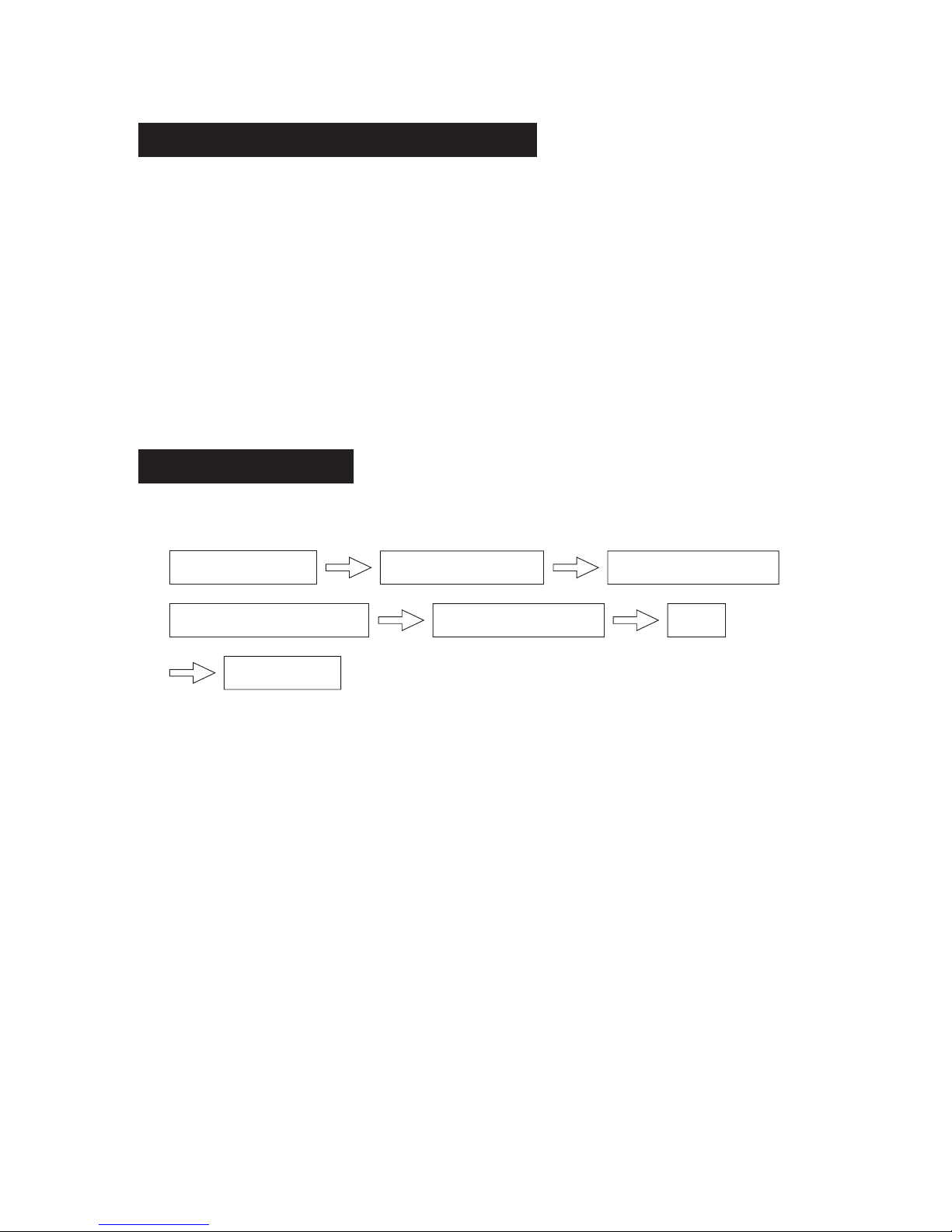
Please check whether the accessories are of full scope. If there are some fittings free from use,
please restore them carefully.
Select the location
Install the connecting pipe
Install the indoor unit
Connect the drain pipe
Install the outdoor unit
Wiring
INSTALLATION INFORMATION
ACCESSORIES
Test operation
Page 4

A place where there is enough room for installation and maintenance.
The ceiling is structurally sound to hold the Indoor Unit.
A place that is well ventilated and the influence of weather is the least.
A place that the airflow can reach every corners of the room.
A place where the refrigerant connecting pipe and drain pipe can reach out easily.
A place free of flammable gas or corrosive gas leakage.
A place where there is no direct affection from man-made high-voltage current and highfrequency wave.
A place which is far from noises and vibration.
A place where there is enough room for installation and maintenance.
A place where there is no obstruction for good air flow. And a place avoids strong wind.
A dry and well ventilating place.
The supporting surface is flat and horizontal and can endure the weight of outdoor unit without
adding extra noises and vibration.
Ensure that the operation noise and the discharged air do not disturb your neighbors.
A place avoids flammable gas.
A place which is easy to install the connecting pipe or electrical wire.
Children could not reach.
The condensate should be well drained away by the drain hole to an appropriate place, not to
the wall or road, so as not to interfere other people or public.
Do not install at a public corridor or a place which affect the appearance of the city.
Location in the following places may cause malfunction of the machine. (If unavoidable, please
consult your local dealer.)
a. A place with mineral oil, such as machine oil.
b. A saline place such as a seashore vicinity.
c. A place with sulphur gas.
d. A place where voltage fluctuated in a wide range.
e. A place with oil gas, such as kitchen.
f. A place where high-frequency waves are generated.
g. A place with flammable gas or material.
h. A place with acid or alkaline gas.
i. Other special conditions.
.
.
.
.
.
.
.
.
.
.
.
.
.
.
.
.
.
.
INDOOR UNIT SHOULD BE INSTALLED AT:
OUTDOOR UNIT SHOULD BE INSTALLED AT:
CAUTIONS
INSTALLATION LOCATION
2
Page 5

A 280
1. Decide the correct carry-in path.
2. Move this unit as originally packaged as possible.
3. If the air conditioner is installed on a metal part of the building, it must be electrically insulated
according to the relevant electrical code.
4. If installing in a lonely building or at a high position where it is hot and humid with frequent
thunderstorm, lightning-protection equipment is necessary.
NOTES BEFORE INSTALLATION
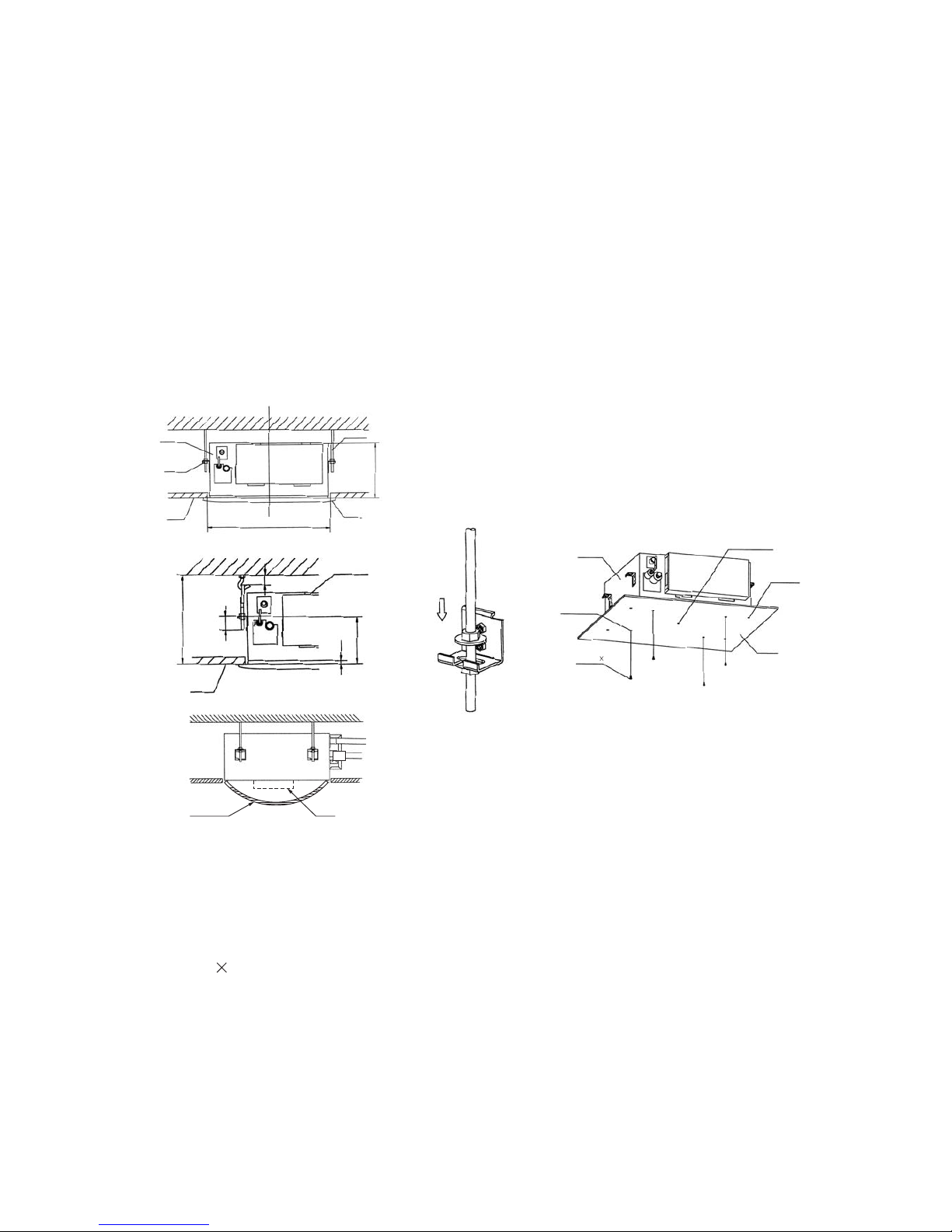
1. Install the main body
Necessary roomNecessary room
A. The existing ceiling (to be horizontal)
a. Please cut a quadrangular hole of 600 600mm in the ceiling according to the shape of the
installation paper board. (Refer to Chart3,4)
The center of the hole should be at the same position of that of the air conditioner body.
Determine the lengths and outlets of the connecting pipe, drain pipe and cables.
To balance the ceiling and to avoid vibration, please enforce the ceiling when necessary.
b. Please select the position of installation hooks according to the hook holes on the installation
board.
Drill four holes of 12mm, 50~55mm deep at the selected positions on the ceiling. Then embed
the expansible hooks(fittings).
Face the concave side of the installation hooks toward the expansible hooks. Determine the
length of the installation hooks from the height of ceiling, then cut off the unnecessary part.
If the ceiling is extremely high, please determine the length of the installation hook according to
facts.
Cut the installation hook open in the middle position, then use apropriate length of reinforcing
rod ( 12) to weld together.
Chart 1
Chart 3
Chart 2
Ground
Outlet
Drain side
A
422 28.5
67
401(Hook location)
611(Hook location)
580(Body)
580(Body)
600(Ceiling hole)
600(Ceiling hole)
650(Panel)
650(Panel)
Outlet
>2300
Inlet
INDOOR UNIT INSTALLATION
.
.
.
.
.
.
.
.
.
.
.
.
.
.
>1000
>1000
>1000
>1000
3
Page 6
The length could be calculated from Chart5:
Length=210+L(in general, L is half of the whole length of the installation hook)
c. Please adjust the hexangular nuts on the four installation hooks evenly, to ensure the balance
of the body.
Use the transparent hose filled with water to check the lever of the main body from the four
sides or diagonal line direction, the lever indicator also can check the lever from four sides of
the main body Refer to chart 6)
If the drainpipe is awry, leakage will be caused by the malfunction of the water-level switch.
Adjust the position to ensure the gaps between the body and the four sides of ceiling are even.
The body's lower part should sink into the ceiling for 10~12mm (Refer to chart5).
Locate the air conditioner firmly by wrenching the nuts after having adjusted the body's position
well.
.(
.
.
.
.
B. New built houses and ceilings
a. In the case of new built house, the hook can be embedded in advance (refer to the A.b
mentioned above). But it should be strong enough to bear the indoor unit and will not become
loose because of concrete shrinking.
b. After installing the body, please fasten the installation paper board onto the air conditioner with
bolts (M5 16) to determine in advance the sizes and positions of the hole opening on ceiling.
Please first guarantee the flatness and horizontal of ceiling when installing it.
Refer to the A.a mentioned above for others.
c. Refer to the A.c mentioned above for installation.
d. Remove the installation paper board.
L
10-12
176
34
Chart 6
Chart 5
Chart 4
Chart 7 Chart 8
Colourless
trans parent pipe
Ceiling
Body
Ceiling
Panel
Hook
A
285
Nut
Body
600
Body
Fixing hole
Installation
paper board
Screw M5 16
(Accessory)
Installation
paper board
Hook hole
Central hole
H(ceiling height)
Horizontal
indicator
4
Page 7
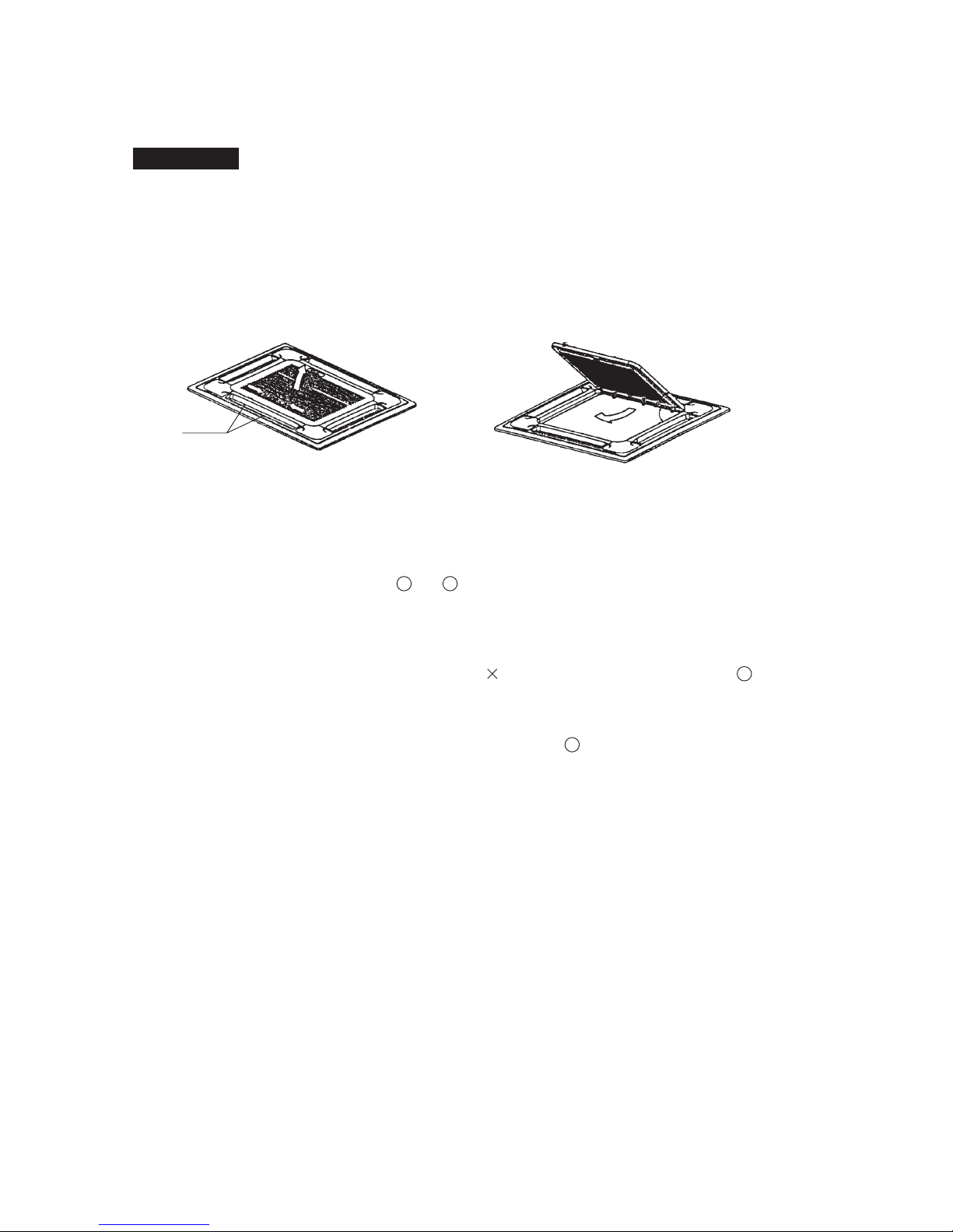
2. Install The Panel
(1) Remove the inlet grid.
(2) Install the panel
(3) Hang the air-in grid to the panel, then connect the lead terminator of the swing motor
and that of the control box with corresponding terminators on the body respectively.
(4) Relocate the air-in grid in the procedure of reversed order, install the air-in grid.
CAUTIONS:
CAUTIONS
Never put the panel face down on floor or against the wall, or on bulgy objects.
Never crash or strike it.
a. Slide two grid switches toward the middle at the same time, and then pull them up. (Refer to
chart 9)
b. Draw the grid up to an angle of about 30 , and remove it. (Refer to chart 10)
o
a. Align the swing motor on the panel to the water receiver of the body properly. (Refer to chart 11)
b. Hang the four fixed rope of the main body to the installation cover and the other three covers of
the swing motor: (Refer to chart 11 and )
c. Install the panel on the main body with bolt (M5 16) and washer. (Refer to chart 11 )
d. Adjust the four panel hook screws to keep the panel horizontal, and screw them up to the ceiling
evenly.
e. Regulate the panel in the direction of the arrow in Chart 11 slightly to fit the panel's center to
the center of the ceiling's opening. Guarantee that hooks of four corners are fixed well.
f. Keep fastening the screws under the panel hooks, until the thickness of the sponge between the
body and the panel's outlet has been reduced to about 4~6mm. The edge of the panel should
contact with the ceiling well. (Refer to chart 12)
Malfunction described in Chart 13 can be caused by inappropriate tightness the screw.
If the gap between the panel and ceiling still exists after fastening the screws, the height of the
indoor unit should be modified again. You can modify the height of the indoor unit through the
openings on the panel's four corners, if the lift of the indoor unit and the drainpipe is not
influenced (refer to chart 14-right).
12
4
3
The installation cover of the swing motor must sink into the corresponding water receiver.
.
.
.
.
45
o
Grid switch
Chart9
Chart 10
5
Page 8

Keep this unit away from direct radiation of the sun or other heaters.
If unavoidable, please cover it with a shelter.
In places near coast or with a high attitude where the wind is violent, please install the outdoor
unit against the wall to ensure normal performance.
Use a baffle when necessary.
In the case of extremely strong wind, please prevent the air from flowing backwards into the
outdoor unit. (Refer to chart 15)
Locate the outdoor unit as close to the indoor unit as possible.
The minimum distance between the outdoor unit and obstacles described in the installation
chart does not mean that the same is applicable to the situation of an airtight. Leave open two
of three directions A,B,C..
No obstacles near the air outlet. When install in the balcony the
height of the balcony grill should be less than 1m, Otherwise, it
must be install on the metal frame for ventilate well.
For the cooling and heating type, please use the concrete to
increase the base when the stableness is not good enough.
If need suspending installation, the installation bracket should accord with technique
requirement in the installation bracket diagram. The installation wall should be solid brick,
concrete or the same intensity construction, or actions to reinforce, damping, supporting should
be taken.
.
.
.
.
.
.
.
.
OUTDOOR UNIT INSTALLATION
CAUTIONS
Cover
Steel rope
Body
Panel foam2
Ceiling
Panel foam
Air plate
Panel
Panel foam1
Panel sealing foam
Inlet air
Outlet air
Swing motor side
Ceiling
Leakage
Hexagon nut
Ceiling
Horizontal adjust ment
Dew
Swing motor installation cover
Drain side
Chart 11
Chart 13
Chart 14
Chart 12
Bolt, washer
Chart 15
Strong wind
X
6
1
2
4
3
Page 9

NECESSARY ROOM FOR INSTALLATION AND MAINTENANCE
Never install the outdoor unit in a seal place without vertilation.
If possible, please remove the obstacles nearby to prevent the performance from being impeded
by too little of air circulation.
.
.
The minimum distance between the outdoor unit and obstacles described in the installation
chart does not mean that the same is applicable to the situation of an airtight room. Leave open
two of the three directions (A,B,C)
Since the gravity center of this unit is not at its physical center, so please be careful when lifting
it with a sling.
Never hold the air-in of the outdoor unit to prevent it from deforming.
Do not touch the fan with hands or other objects.
Do not lean it more than 45 , and do not lay it sidelong.
Please fasten the feet of this unit with bolts (M10) firmly to prevent it from collapsing in case of
earthquake or strong wind.
Make concrete foundation. (Refer to chart 17)
o
Fix the outdoor unit with the anchor bolts at a place which is not exposed to a strong wind.
Use M10 anchor bolts.
If need suspending installation, the installation should accord with the technique requirement in
the Manual.
.
.
.
.
.
.
.
.
.
.
CAUTIONS
MOVING AND INSTALLING
Anchor bolts arrangement of outdoor unit (Unit: mm)
>30cm
>30cm
>60cm
>60cm
>200cm
A
B
C
(Wall or obstacle)
Necessary wide
Fix with bolt
Deep
foundation
air inlet
air inlet
air inlet
Chart 16
Chart 17
7
Supending installation on the loosen texture wall is not allowed.
If it is unavoidable, the intensity construction and endure weight and the quantity air conditioners
installed in the same wall must be considered, actions to reinforce and protect should be taken
to secure the unit works properly.
The connection between bracket and wall, bracket and the air conditioner should be firm, stable
and reliable.
.
.
Page 10

Check whether the height drop between the indoor unit and outdoor unit, the length of refrigerant
pipe, and the number of the bends meet the following requirements:
The max height drop ................................................................................................... 20m
(If the height drop is more than 10m, you had better put the outdoor unit over above the indoor
unit.)
The length of refrigerant pipe ...................................................................... less than 30m
The number of bends ..................................................................................... less than 15
1. Locate The Pipe
a) Measure the necessary length of the connecting pipe.
b) Drill a hole in the wall (suitable just for the size of the wall conduit, 90mm in general), then set
on the fittings such as the wall conduit and its cover.
c) Bind the connecting pipe and the cables together tightly with binding tapes. Do not let air in,
which will cause water leakage by condensation.
d) Pass the bound connecting pipe through the wall conduit from outside. Be careful of the pipe
allocation to do no damage to the tubing.
2. Connect the pipes.
a) Connect the indoor unit at first, then the outdoor unit.
Bend the tubing in proper way. Do not harm them.
CAUTIONS
Daub the surfaces of the flare pipe and the joint nuts with frozen oil, and wrench it for 3~4
rounds with hands before fasten the flare nuts. (Refer to chart 18)
Be sure to use two wrenches simultaneously when you connect or disconnect the pipes.
b) The stop valve of the outdoor unit should be closed absolutely (as original state). Every time
you connect it, first loosen the nuts at the part of stop valve, then connect the flare pipe
immediately (in 5 minutes). If the nuts have been loosened for a long time, dusts and other
impurities may enter the pipe system and may cause malfunction later. So please expel the air
out of the pipe with refrigerant before connection.
The standard length of connecting pipe is no more than 8m, choose appropriate position for
both indoor and outdoor unit to make the connecting pipe as short as possible.
Do not let air, dust, or other impurities fall in the pipe system during the time of installation.
The connecting pipe should not be installed until the indoor and outdoor units have been fixed
already.
Keep the connecting pipe dry, and do not let moisture in during installation.
.
.
.
.
.
.
.
THE PROCEDURE OF CONNECTING PIPES
INSTALL THE CONNECTING PIPE
Use frozen oil
Bend the pipe with thumb
Make the end straight
min-radius 100mm
Chart 18
Chart 19
Chart 20
8
Page 11

Expel the air (refer to the "Expel The Air") after connecting the refrigerant pipe with the indoor
unit and the outdoor unit. Then fasten the nuts at the repair-points.
The bending angle should not exceed 90 .
Bending position is preferably in the bendable pipe. The larger the better it is.
Do not bend the pipe more than three times.
o
Cut out a desired concave at the bending part of the insulating pipe. Then expose the pipe
(cover it with tapes after bending).
To prevent collapsing or deforming, please bend the pipe at its biggest radius.
Use bender to get a small radius pipes.
Be sure use the same insulating materials when you buy the brass pipe. (Thickness over 9mm
in general)
NOTICES FOR BENDABLE PIPE
BEND THE CONNECTING PIPE OF SMALL WALL THICKNESS
USE THE MARKET BRASS PIPE
3. Then, open the stem of stop valves of the outdoor unit to make the refrigerant pipe connecting
the indoor unit with the outdoor unit in fluent flow.
4. Be sure of no leakage by checking it with leak detector or soap water.
5. Necessary refrigerant capacity:
6. Cover the joint of the connecting pipe to the indoor unit with the soundproof insulating sheath
(fittings), and bind it well with the tapes to prevent leakage.
.
.
.
.
.
.
.
.
Please record and reserve well the refrigerant stow capacity of your air conditioner for later
maintenance.
.
Less than 8m (one-way)
7000-12000Btu/h
18000Btu/h
0.03kg/m (L-8)m
LENGTH (L)
TYPE
Added Refrigerant When
Over 8m(one-way)
1. Cut a pipe with a pipe cutter.
2. Insert a flare nut into a pipe and flare the pipe.
FLARING
EXPEL THE AIR
REFRIGERANT PIPE CONNECTING
90
90 4
45 2
A
lean
crude
burr
Chart 21 Chart 22
Table 1
A(mm)
8.7
8.3
15.8
15.4
max
min
Outsidediameter
6.35mm
12.7mm
9
Make sure the refrigerant added into the air conditioner is liquid form in any case.
.
(For R22,R407C,R410A
Heating&Cooling Type)
(For R22,R407C,R410A
Heating&Cooling Type)
7000-12000Btu/h
18000Btu/h
(For R22,R407C,R410A
Cooling onlyType)
(For R22,R407C,R410A
Cooling only Type)
Page 12

FASTEN THE NUT
Put the connecting tubing at the proper position,
wrench the nuts with hands then fasten it with a
wrench. (Refer to chart 23)
Need A5mm hexagon wrench.
When use vacuum pump, Please ask the qualified service personnel to do it.
.
.
.
CAUTION
Too large torque will harm the bellmouthing and too
small will cause leakage. Please determine the
torque according to Table 2.
Chart 23
Table 2
Torque
Tubing Size
6.35mm
1420~1720N.cm
(144~176kgf.cm)
4950~6030N.cm
(504~616kgf.cm)
12.7mm
Select the measure of expelling the air according the following table
The length fo the connecting pipe (one way) The measure of expelling the air
Less than 8m Use Vacuum Pump
8~30m
Use Vacuum Pump
Expel the air
10
Page 13

(Refer to Chart 25, Chart24)
(Please refer to its manual for the way of using manifold valve)
1. Loosen and remove the maintenance nuts of stop valves A and B, and connect the charge hose
of the manifold value with the maintenance terminal of stop valve A. (Be sure that stop valves
A and B are both closed)
2. Connect the joint of the charge hose with the vacuum pump.
3. Open the Lo-lever of the manifold valve completely.
4. Turn on the vacuum pump. At the beginning of pumping, loosen the maintenance terminator
nut of stop valve B a little to check whether the air comes in (the sound of the pump changes,
and the indicator of compound meter turns below zero). Then fasten the nut.
5. When the pumping has finished, close the Lo-lever of the manifold valve completely and turn
off the vacuum pump.
When you have pumped for over 15 minutes, please confirm that the indicator of multi-meter is
on -1.0 10 Pa(-76cmHg).
6. Loosen and remove the quadrangle cover of stop valves A and B to open stop valve A and B
completely, then fasten them.
7. Disassemble the charge hose from the repair-mouth of stop valve A, and fasten the nut.
5
Expel the air with a vacuum pump
.
Open the valve stem until it reaches the limitator. Do not open it any further.
Fasten the stop valves with a wrench or similar tools.
The wrench torque is listed in the table 2 mentioned above.
.
.
.
Operate the stop values
Manifold valve
Multi-meter Pressure meter
Hi-lever
Charge hose
Charge hose
Vacuum pump
Lo-lever
Lo-lever
-76cmHg
Chart 25
11
A
C
D
B
6.35mm
Trap
Pipe joint
Indoor unit
Outdoor unit
Gas-side
Liquid side
12.7mm
Chart 24
Page 14

Check all the joints with the leak detector or
soap water.
(See Chart 26 as a reference illustration)
NOTE: in the chart
A..............Lo-stop valve
B..............Hi-stop valve
C, D.........Joints of the connecting
pipe to the indoor unit.
CHECK THE LEAKAGE
HEAT INSULATION
CONNECT THE DRAIN PIPE
Be sure to with insulating materials cover all the exposed parts of the flare pipe joints and
refrigerant pipe on the liquid-side and the gas-side. Ensure that there is no gap between them.
Incomplete insulation may cause water condensation.
.
.
You can use a polyethylene tube as the drainpipe (out-dia. 31~32mm, in-dia. 25mm). It could
be bought at local market or from your dealer.
Set the mouth of the drainpipe onto the root of the body's pump-pipe, and clip the drainpipe and
the out-let pipe sheath (fittings) together firmly with the out-let pipe clasp (fitting).
The body's pump pipe and the drainpipe (especially the indoor part) should be covered evenly
with the out-let pipe sheath (fittings) and be bound tightly with the constrictor to prevent
condensation caused by entered air.
To prevent water from flowing backwards into the air conditioner while the air conditioner stops,
please lean the drainpipe down toward outdoor (outlet-side) at a degree of over 1/50. And
please avoid any bulge or water deposit. (Refer to Chart 27.a)
Do not drag the drainpipe violently when connecting to prevent the body from being pulled.
Meanwhile. one support-point should be set every 1~1.5m to prevent the drainpipe from yielding
(Refer to Chart 27.b). Or you can tie the drainpipe with the connecting pipe to fix it. (Refer to
Chart 27.c)
In the case of prolonged drainpipe, you had better tighten its indoor part with a protection tube
to prevent it from loosing.
If the outlet of the drainpipe is higher than the body's pump joint, the pipe should be arranged
as vertically as possible. And the lift distance must be less than 200mm, otherwise the water will
overflow when the air conditioner stops. (Refer to Chart 28)
.
.
.
.
.
.
.
1. Install the drainpipe of the indoor unit
CAUTIONS: Use your strength carefully to prevent the pump-pipe from breaking.
12
D
B
C
A
Electrical Box Cover
Check-point of outdoor unit
Check-point of indoor unit
Chart 26
Page 15

The end of the drainpipe should be over 50mm higher than the ground or the bottom of the
drainage chute, and do not immerse it in water. If you discharge the water directly into sewage
be sure to make a U-form aquaseal by bending the pipe up to prevent the smelly gas entering
the house through the drain pipe.
CAUTIONS: All the joints of the drain system must be sealed to prevent water leakage.
a
c
b
Lean over 1/50
Lean over 1/50
Pump-pipe clasp
(the fittings)
1-1.5m
1-1.5m
>1.5m
>200mm
<200mm
223mm
Constrict here
Lean over 1/50
Drainpipe
Connecting pipe
Chart 27
Chart 28
13
2. Drainage test
Check whether the drainpipe is unhindered
New built house should have this test done before paving the ceiling.
Remove the test cover, and stow water of about 1500ml to the water receiver through the
stow tube. (Refer to Chart 29)
.
.
Chart 29
1
Stow
Body
Drain pipe
Drain plug
Mater pan
Water receiver
Stow tube
Turn on the power, and operate the air conditioner under the "COOLING" mode. Listen to the
sound of the drain pump. Check whether the water is discharged well (a lag of 1min is allowed
before discharging, according to the length of the drain pipe), and check whether water leaks
from the joints.
If there is any malfunction, please resolve it immediately.CAUTIONS:
2
Stop the air conditioner for there minutes, check if everything is ok. If the drain hose is located
unreasonable, water overflow will cause the Alarm indicator lamp flashing (For both cooling
and heating type or cooling only type), even the water leak out from the water receiver.
3
Page 16

14
3. Drainage Elbow Installation (Cooling Only Type Without)
Fit the seal into the drain elbow, then insert the drain elbow into base pan hole of outdoor unit,
rotate 90 to securely assemble them. Connect the drain elbow with an extension drain hose
(Locally purchased), in case of the condensate draining off the outdoor unit during the heating
(Refer to Chart 30)
O
mode.
Check the drain pump whether drain water immediately when alarm sound for the high water
lever. If the water lever can't come down below to the limited water lever, the air conditioner
will stop. Restart it untill turn off the power and drain off all the water.
Turn off the power, drain the water away.
The drain plug is used to empty the water-receiver for maintenance of the air conditioner. Please
stuff it imposition at all times during operation to avoid leakage.
.
Chart 30
5
The base pan hole
of outdoor unit
The base pan
of outdoor unit
Drain elbow
Drain
elbow
Seal
Seal
1. The air conditioner should use separate power supply with rated voltage, the voltage of power
supply must be within90%~110% of rated value.
2. The external power supply to the air conditioner should have ground wiring, which is linked to
the ground wiring of the indoor and outdoor unit.
3. The wiring work should be done by qualified persons according to circuit drawing.
4. A disconnection device having an air gap contact separation in all active conductors should
incorporated in the fixed wiring according to the National wiring regulation.
5. Be sure to locate the power wiring and the signal wiring well to avoid cross-disturbance and
their contact with connecting pipe or stop valve body.
6. The wiring attached to this air conditioner is 6m long. Be sure to prolong it with wiring of the
same type and proper length if necessary. Generally, do not twist two wiring together unless the
joint is soldered well and covered with insulator tape.
7. Do not turn on the power until you have checked carefully after wiring.
8. The yellow and green wire can only be used to link to the ground wiring.
CAUTION
WIRING
Page 17

15
NOTE:
1.The connecting wiring of strong electric signal for 18000Btu/h type(R22,cooling only) is
just .
2. Please remember the surroundings (environmental temperature, direct sunlight, rain etc.)
3. We consider the minimal size of the metal core as the wire size. So it is recommended you
adopt a thicker one as the power conducting wire so as to avoid power decrease;
4. Connect the grounded wire to both indoor and outdoor units;
5. This table is just an on-site wire-connecting example. For details, please refer to relative
National criteria.
3x2.0
mm
2
The length of the power wire and connecting-wire which connects the indoor unit to the outdoor
unit. (The figure given below shows a suitable length)
THE SPECIFICATION OF POWER
Indoor
Unit
Outdoor
Unit
A
B
Distance between indoor/outdoor unit
Entrance
of the Indoor Unit
Entrance
of the outdoor Unit
Chart 31
A()
()mm
2
TYPE(Btu/h)
POWER
GROUND WIRING
OUTDOOR UNIT POWER
WIRING
STRONG ELECTRIC
SIGNAL
INDOOR/OUTDOOR
CONNECTING
WIRING
CIRCUIT BREAKER/FUSE
INDOOR UNIT POWER WIRING
PHASE
FREQUENCY AND VOLT
WEAK ELECTRIC
SIGNAL
1-PHASE
40/25
3x2.0
7000-12000Btu/h
18000Btu/h
(For R22, R407C and R410A,
Heating&Cooling type )
220-240V~, 50Hz
(For R22, R407C and R410A,
Cooling only type )
40/25
2.0
3x2.0
7000-12000Btu/h
18000Btu/h
(For R22, R407C and R410A,
Cooling only type )
(For R22, R407C and R410A,
Heating&Cooling type )
1x0.5
1-core shield wire
40/25
1x0.5
1-core shield wire
40/25
4x2.0
4x2.0
(3x2.0)
5x2.0
5x2.0
2.0
3x2.0
ATTENTION: Chart 32 is based on the standard model, which may look a little different from
own outdoor unit.
your
Note: The wiring could not touch the refrigerant pipe.
Electrical box
big handle
Terminal block
Signal wire
Electrical box
Indoor / outdoor
unit signal wire
Indoor / outdoor
unit powerard
Cord clamp
Chart 32
3x2.0
2.0
2.0
Page 18

Air Condition Link-Circuit
7000~12000Btu/h type(1-phase)
For R407C,heating&cooling
3. Remove the protection board.
Notice:
Disassemble the bolts from the maintenance board, and pull it in the direction of the arrow to
remove the protection board.
Do not scratch the surface during operation.
16
Installing wiring chart, refer to link circuit chart for defails
WIRING CHART
Switch/Fuse
(Available locally)
Indoor Unit
Strong elec-signal link wiring
Weak elec-signal link wiring
Power
Power wiring (indoor)
Power linking wiring (outdoor)
Outdoor unit
Connect the unit to the ground correctly, otherwise it will affect the anti-interference of the unit.
The cooling only type without weak elec-signal link wiring.Note:
.
Chart 33
Chart 34
POWER:
220-240V~50Hz
Page 19

17
Air Condition Link-Circuit
7000~12000Btu/h type(1-phase)
For R407C,cooling only
Chart 36
Chart 35
Air Condition Link-Circuit
18000Btu/h type(1-phase)
For R407C,R410A,heating&cooling
POWER:
220-240V~50Hz
POWER:
220-240V~50Hz
12000Btu/h type(1-phase)
For R410A,heating&cooling
Page 20

Air Condition Link-Circuit
18000Btu/h type(1-phase)
For R407C,R410A,cooling only
Air Condition Link-Circuit
18000Btu/h type(1-phase)
For R22,heating&cooling
Chart 38
Chart 37
18
POWER:
220-240V~50Hz
POWER:
220-240V~50Hz
Page 21

Air Condition Link-Circuit
18000Btu/h type(1-phase)
For R22,cooling only
Chart 39
19
CAUTION: Wrong wiring connections may cause some electrical parts to malfunction.
1. Remove the electric parts cover from the outdoor unit.
2. Connect the connective cables to the terminals as identified with their respective matched
numbers on the terminal block of indoor and outdoor units.
(Connective cable sheath length to be removed and insert into the terminal block.)
3. To prevent the ingress off water, from a loop of the connective cable as illustrated in the
installation diagram of indoor and outdoor units.
4. Insulate unused cords (conductors) with PVC-tape. Process them so they do not touch any
electrical or metal parts.
OUTDOOR UNIT
Cord wire
40mm
10mm
Chart 40
POWER:
220-240V~50Hz
Page 22

TEST OPERATION
1. The test operation must be carried out after the entire installation has been completed.
2. Please confirm the following points before the test operation.
3. Test operation
The indoor unit and outdoor unit are installed properly.
Tubing and wiring are correctly completed.
The refrigerant pipe system is leakage-checked.
The drainage is unimpeded.
The heating insulation works well.
The ground wiring is connected correctly.
The length of the tubing and the added stow capacity of the refrigerant have been recorded.
The power voltage fits the rated voltage of the air conditioner.
There is no obstacle at the outlet and inlet of the outdoor and indoor units.
The gas-side and liquid-side stop valves are both opened.
The air conditioner is pre-heated by turning on the power.
Set the air conditioner under the mode of "COOLING" with the remote controller, and check the
following points per the "Owner's Manual". If there is any malfunction, please resolve it as per
chapter "Troubles And Causes" in the "Owner's Manual".
1) The indoor unit
a. Whether the switch on the remote controller works well.
b. Whether the buttons on the remote controller works well.
c. Whether the air flow louver moves normally.
d. Whether the room temperature is adjusted well.
e. Whether the indicator lights normally.
f. Whether the temporary buttons works well.
g. Whether the drainage is normal.
h. Whether there is water leakage by condensation because of the connecting pipe and drain
hose not bind well.
i. Open the air-in grid, check whether any water is leaked, expecially at the drain plug.
j. Whether there is vibration or abnormal noise during operation.
k. Whether the air conditioner heats well in the case of the HEATING/COOLING type.
2) The outdoor unit
a. Whether there is vibration or abnormal noise during operation.
b. Whether the generated wind, noise, or condensed of by the air conditioner have influenced
your neighborhood.
c. Whether any of the refrigerant is leaked.
.
.
.
.
.
.
.
.
.
.
.
.
A protection feature prevents the air conditioner from being activated for approximately 3 minutes
when it is restarted immediately after shut off.
CAUTIONS
20
Page 23

MDV04I-009cW
2200017068
 Loading...