

Mitsubishi SLH-1AR(1).TH, SLH-1.6AR(1).TH, SLH-2AR(1).TH, SL-1AR.TH, SL-1.6AR.TH Service Manual
...Page 1
SPLIT-TYPE, HEAT PUMP AIR CONDITIONERS
ON/OFF
RESET
TOO
WARM
TOO
COOL
MODE
AUTO COOL
DRY
HEAT
FAN
VANE
SELECT
TIME
h
ON/OFF
RESET
TOO
WARM
TOO
COOL
MODE
COOL
DRYFAN
FAN
VANE
SELECT
TIME
h
SPLIT-TYPE, AIR CONDITIONERS
TECHNICAL & SERVICE MANUAL
No. OC280
REVISED EDITION-B
Series SLH/SL
Ceiling Cassettes
Indoor unit
[Model names] [Service Ref.]
SLH-1AR SLH-1AR.TH
SLH-1AR
SLH-1.6AR SLH-1.6AR.TH
SLH-1.6AR
SLH-2AR SLH-2AR.TH
SLH-2AR
SL-1AR SL-1AR.TH
SL-1AR.TH-T
SL-1.6AR SL-1.6AR.TH
SL-1.6AR.TH-T
SL-2AR SL-2AR.TH
SL-2AR.TH-T
1.TH
1.TH
1.TH
Revision:
•SLH-1AR1.TH, SLH-1.6AR1.TH and
SLH-2AR1.TH are added in REVISED
EDITION-B.
•Please void OC280 REVISED
EDITION-A.
•This manual does not cover the
following outdoor units. When
servicing them, please refer to the
service manual No.OC282 REVISED
EDITION-B and this manual in a set.
SUH-1VR.TH, SUH-1.6VR2.TH,
SUH-2VR1.TH, SUH-2VR2.TH,
SU-1VR.TH, SU-1.6VR2.TH,
SU-2VR1.TH, SU-1VR.TH-T,
SU-1.6VR2.TH-T, SU-2VR1.TH-T
[For SLH- • AR1.TH]
NOTE:
This service manual descrides only for
the indoor unit and the connected outdoor
unit of SUH series. In PUMY series, refer
to the service manual outdoor unit and
“R-CONVERTER UNIT” for PUMY series.
CONTENTS
1. TECHNICAL CHANGE ·························2
2. PART NAMES AND FUNCTIONS ········2
3. SPECIFICATIONS·································4
4. OUTLINES AND DIMENSIONS··········34
5. WIRING DIAGRAM·····························36
6.
REFRIGERANT SYSTEM DIAGRAM
INDOOR UNIT
7. DATA ···················································43
8. MICROPROCESSOR CONTROL·······47
9. TROUBLESHOOTING ························56
10. 4-WAY AIR FLOW SYSTEM ··············63
11. DISASSEMBLY PROCEDURE···········65
12. PARTS LIST·······································68
REMOTE CONTROLLER
SLH-1AR
SLH-1.6AR
SLH-2AR
SL-1AR
SL-1.6AR
SL-2AR
·······39
Page 2
1
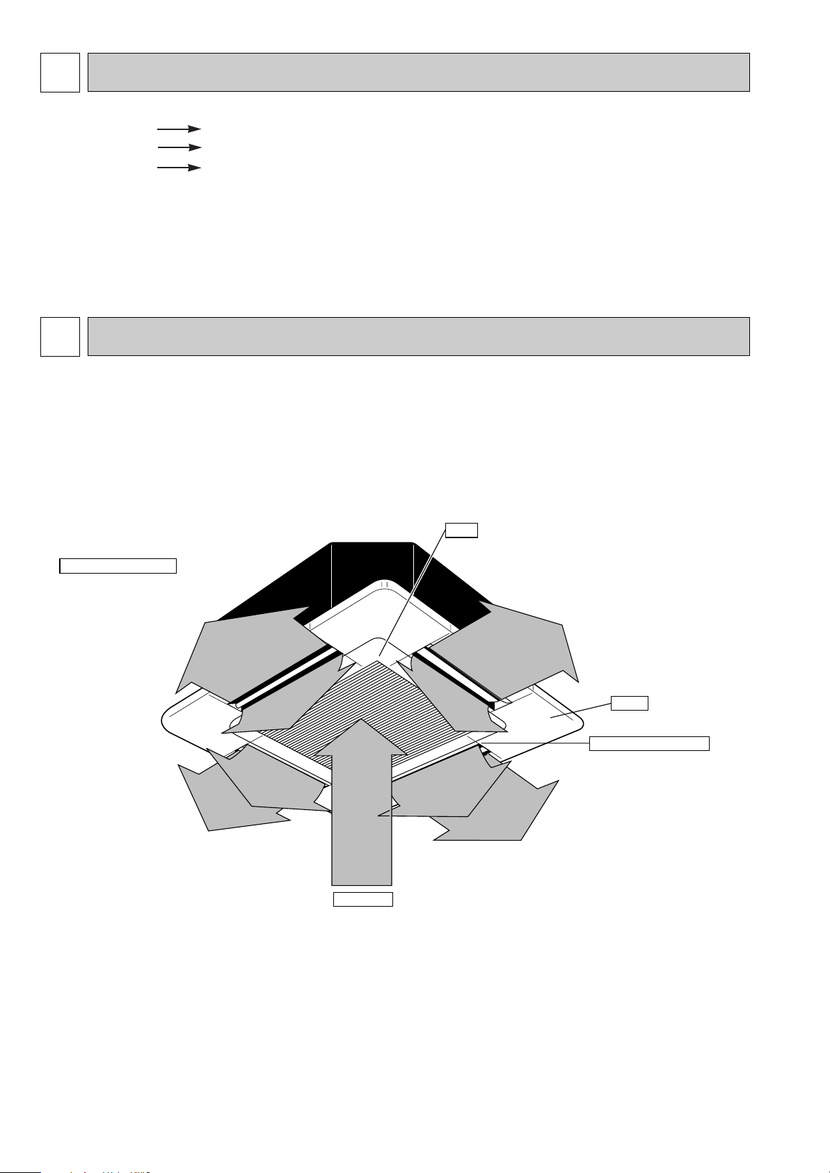
Auto Air Swing Vane
Disperses airflow up and
down and adjusts the angle
of airflow direction.
Grille
Filter
Remove dust and pollutants
from inhaled air
Horizontal Air Outlet
Sets airflow horizontal automatically
during cooling or dehumidifying.
Air Intake
Inhales air from room.
TECHNICAL CHANGE
SLH-1AR.TH SLH-1AR1.TH
SLH-1.6AR.TH SLH-1.6AR1.TH
SLH-2AR.TH SLH-2AR1.TH
1. The indoor controller board changed in order to connect with R-CONVERTER UNIT.
2. Outdoor units of the PUMY series are cnnectable via R-CONVERTER UNIT.
2
PART NAMES AND FUNCTIONS
● Indoor (Main) Unit
SLH-1AR.TH SL-1AR.TH SL-1AR.TH-T
SLH-1.6AR.TH SL-1.6AR.TH SL-1.6AR.TH-T
SLH-2AR.TH SL-2AR.TH SL-2AR.TH-T
SLH-1AR
SLH-1.6AR
SLH-2AR
1.TH
1.TH
1.TH
2
Page 3
ON/OFF
RESET
TOO
WARM
TOO
COOL
MODE
COOL
DRYFAN
FAN
VANE
SELECT
TIME
h
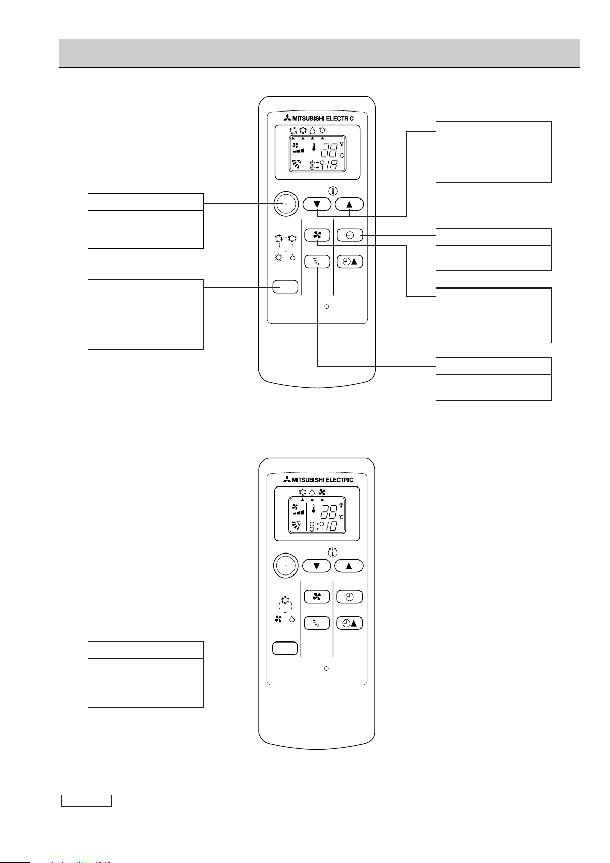
● Remote controller
ON / OFF button
Pushing button starts
operation. Pushing again
stops operation.
MODE SELECT button
This button is used to change
between auto, cooling,
heating and drying operation
modes. (SLH)
h
ON/OFF
AUTO COOL
HEAT
MODE
DRY
TOO
WARM
FAN
VANE
TOO
COOL
SELECT
TIME
RESET
SLH-1AR.TH SLH-1AR1.TH
SLH-1.6AR.TH SLH-1.6AR
SLH-2AR.TH SLH-2AR
1.TH
1.TH
SET TEMPERATURE
button
SET TEMPERATURE
button sets and any
desired room temperature.
TIMER SELECT button
Used for selecting timed
starting or stopping.
FAN SPEED button
This button is used to set
fan speed to low, medium
or high.
VANE CONTROL button
Used to change the airflow
direction.
MODE SELECT button
This button is used to
change between cooling,
drying and fan operation
modes. (SL)
SL-1AR.TH SL-1AR.TH-T
SL-1.6AR.TH SL-1.6AR.TH-T
SL-2AR.TH SL-2AR.TH-T
Attention :
● Avoid operation of buttons with fingernails or other sharp objects. Sharp objects may scratch remote controller.
3
Page 4
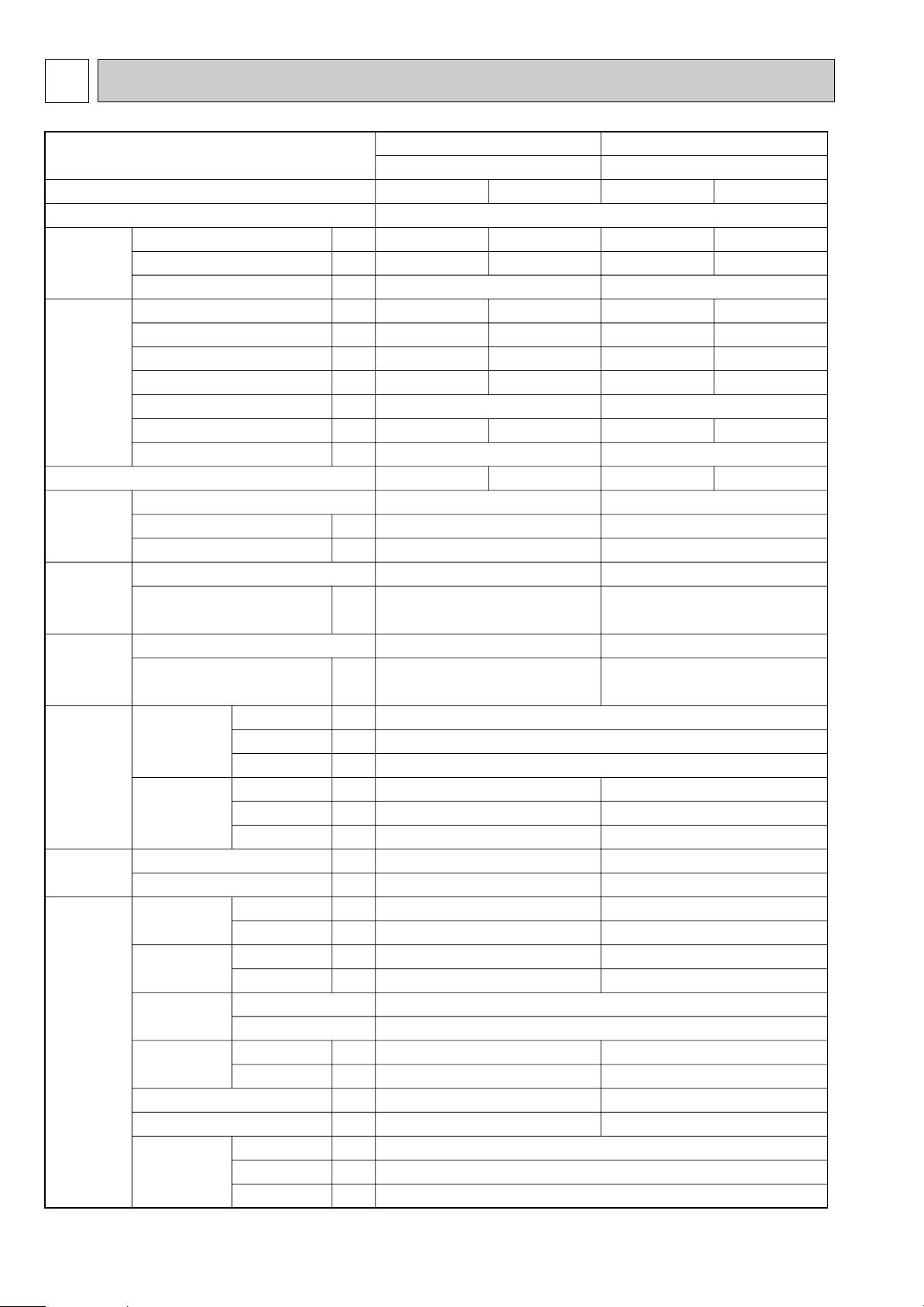
3
Function
Power supply
Service Ref.
Capacity
Dehumidification
Air flow
Running current
Power input
Auxiliary heater
Power factor
Starting current
Compressor motor current
Fan motor current
kW
R/h
K/h
A
W
A(kW)
%
A
A
A
W
"
"
"
mm
mm
mm
mm
mm
mm
kg
kg
dB
dB
rpm
rpm
m/W
m
kg
L
k"
k"
k"
Capacity
Electrical
data
Coefficient of performance (C.O.P)
Compressor
Indoor
fan motor
Outdoor
fan motor
Dimensions
Indoor unit
[Grille]
Indoor unit [Grille]
Width
Height
Depth
Width
Height
Depth
Indoor unit
Outdoor unit
Indoor unit
Outdoor unit
Indoor unit
Outdoor unit
Air speed
Coverage range
RT11(at 25:)
RT12(at 25:)
RT61(at 0:)
Sound level
(Hi)
Fan speed
(Hi)
Fan speed
regulator
Outlet air speed
and coverage range
Outdoor unit
Outdoor unit
Refrigerant filling capacity(R-22)
Thermistor
Weight
Special
remarks
Model
Output
Winding resistance (at 20:)
Model
Winding resistance (at 20:)
Model
Winding resistance (at 20:)
SUH-1VR.TH
Single phase, 220-240V, 50Hz
Cooling
SUH-1.6VR2.TH
SLH-1AR.TH SLH-1AR
1.TH SLH-1.6AR.TH SLH-1.6AR1.TH
2.5-2.5
0.9
4.5-4.3
970-1010
—
98-98
4.10-3.88
2.58-2.48
Heating
3.0-3.1
—
4.7-4.5
1010-1050
—
98-97
4.30-4.08
2.97-2.95
33
36
47
580-620
710-760
3.4
3.7
0.8
MS56 O 0.30
RH-174VGHT
800
C-R: 3.30 C-S: 5.80
PK6V11-LA
WHT-BLK : 308 BLK-BLU : 57
BLU-YLW : 35 YLW-BRN : 39
BRN-RED : 271
PN6V23-UA
WHT-BLK : 353
BLK-RED : 321
780
540
255
15 [3]
43
39
50
670-700
780-820
3.7
4.1
1.4
MS56 O 0.52
570 [650]
208 [20]
570 [650]
3
1
10
10
33.18
600
Cooling
4.0-4.1
1.8
7.5-7.5
1600-1700
—
97-94
6.91-6.88
2.50-2.41
Heating
4.5-4.6
—
7.1-7.1
1510-1610
—
97-94
6.51-6.48
2.98-2.86
RH-277VHAT
1300
C-R: 1.80 C-S: 3.00
PK6V21-LA
WHT-BLK : 384 BLK-BLU : 111
BLU-YLW : 49 YLW-BRN : 46
BRN-RED : 311
RA6V40-EE
WHT-BLK : 130
BLK-RED : 135
850
605
290
16.5 [3]
660
21-23 33-36
0.40-0.42 0.59-0.62
Refrigerant oil
SPECIFICATIONS
NOTE:Test conditions
Cooling : Indoor D.B. 27°C W.B. 19°C Outdoor D.B. 35°C W.B. 24°C
Heating : Indoor D.B. 20°C W.B. — Outdoor D.B. 7°C W.B. 6°C
4
Page 5
Service Ref.
Function
Power supply
Capacity
Capacity
Electrical
data
Coefficient of performance (C.O.P)
Compressor
Indoor
fan motor
Outdoor
fan motor
Dimensions
Weight
Special
remarks
NOTE:Test conditions
Cooling : Indoor D.B. 27°C W.B. 19°C Outdoor D.B. 35°C W.B. 24°C
Heating : Indoor D.B. 20°C W.B. — Outdoor D.B. 7°C W.B. 6°C
Dehumidification
Air flow
Running current
Power input
Auxiliary heater
Power factor
Starting current
Compressor motor current
Fan motor current
Model
Output
Winding resistance (at 20:)
Model
Winding resistance (at 20:)
Model
Winding resistance (at 20:)
Width
Indoor unit
[Grille]
Outdoor unit
Indoor unit [Grille]
Outdoor unit
Sound level
(Hi)
Fan speed
(Hi)
Fan speed
regulator
Outlet air speed
and coverage range
Refrigerant filling capacity(R-22)
Refrigerant oil
Thermistor
Height
Depth
Width
Height
Depth
Indoor unit
Outdoor unit
Indoor unit
Outdoor unit
Indoor unit
Outdoor unit
Air speed
Coverage range
RT11(at 25:)
RT12(at 25:)
RT61(at 0:)
kW
R/h
K/h
A
W
A(kW)
%
A
A
A
W
"
"
"
mm
mm
mm
mm
mm
mm
kg
kg
dB
dB
rpm
rpm
m/W
m
kg
L
k"
k"
k"
Cooling
5.0-5.1
10.2-9.8
2230-2310
99-98
9.58-9.15
2.24-2.21
SLH-2AR.TH SLH-2AR1.TH
SUH-2VR1.TH
SUH-2VR
Single phase, 220-240V, 50Hz
2.6
—
NH38VMDT
C-R : 1.07 C-S : 2.26
PK6V21-LB
WHT-BLK : 317 BLK-BLU : 88
BLU-YLW : 52 YLW-BRN : 45
BRN-RED : 301
RA6V50-OF
WHT-BLK : 116
BLK-RED : 111
MS32(N-1) O 1.2
2.TH
660
52-58
0.62-0.65
1700
570 [650]
208 [20]
570 [650]
850
605
290
16.5 [3]
59
40
52
700-730
810-845
3
1
3.7
4.1
1.8
10
10
33.18
Heating
5.4-5.5
—
10.0-9.4
2180-2220
—
99-98
9.38-8.75
2.48-2.48
5
Page 6
Function
Power supply
Service Ref.
Capacity
Dehumidification
Air flow
Running current
Power input
Auxiliary heater
Power factor
Starting current
Compressor motor current
Fan motor current
kW
R/h
K/h
A
W
A(kW)
%
A
A
A
W
"
"
"
mm
mm
mm
mm
mm
mm
kg
kg
dB
dB
rpm
rpm
m/W
m
kg
L
k"
k"
k"
Capacity
Electrical
data
Coefficient of performance (C.O.P)
Compressor
Indoor
fan motor
Outdoor
fan motor
Dimensions
Indoor unit
[Grille]
Indoor unit [Grille]
Width
Height
Depth
Width
Height
Depth
Indoor unit
Outdoor unit
Indoor unit
Outdoor unit
Indoor unit
Outdoor unit
Air speed
Coverage range
RT11(at 25:)
RT12(at 25:)
RT61(at 0:)
Sound level
(Hi)
Fan speed
(Hi)
Fan speed
regulator
Outlet air speed
and coverage range
Outdoor unit
Outdoor unit
Refrigerant filling capacity(R-22)
Thermistor
Weight
Special
remarks
Model
Output
Winding resistance (at 20:)
Model
Winding resistance (at 20:)
Model
Winding resistance (at 20:)
SU-1VR.TH
SU-1VR.TH-T
Single phase, 220-240V, 50Hz
Cooling
SU-1.6VR2.TH
SU-1.6VR2.TH-T
SL-1AR.TH
SL-1AR.TH-T
SL-1.6AR.TH
SL-1.6AR.TH-T
2.6-2.6
1.0
600
4.6-4.4
990-1030
—
98-98
21-23
4.20-3.98
0.40-0.42
2.63-2.52
RH-174VGHT
800
C-R: 3.30 C-S: 5.80
PK6V11-LA
RA6V23-FC
WHT-BLK : 353
BLK-RED : 321
780
540
255
15 [3]
32
36
45
580-620
710-760
3.4
3.7
0.8
MS56 O 0.30
570 [650]
208 [20]
570 [650]
3
1
10
10
33.18
Cooling
4.0-4.1
1.8
660
7.7-7.7
1640-1740
—
97-94
33-36
7.11-7.08
0.59-0.62
2.44-2.36
RH-277VHAT
1300
C-R: 1.80 C-S: 3.00
PK6V21-LA
RA6V40-EE
WHT-BLK : 130
BLK-RED : 135
850
605
290
16.5 [3]
38
39
50
670-700
780-820
3.7
4.1
0.9
MS56 O 0.52
WHT-BLK : 308 BLK-BLU : 57
BLU-YLW : 35 YLW-BRN : 39
BRN-RED : 271
WHT-BLK : 384 BLK-BLU : 111
BLU-YLW : 49 YLW-BRN : 46
BRN-RED : 311
Refrigerant oil
NOTE:Test conditions
Cooling : Indoor D.B. 27°C W.B. 19°C Outdoor D.B. 35°C W.B. 24°C
Heating : Indoor D.B. 20°C W.B. — Outdoor D.B. 7°C W.B. 6°C
6
Page 7
Service Ref.
Function
Power supply
Capacity
Electrical
data
Capacity
Dehumidification
Air flow
Running current
Power input
Auxiliary heater
Power factor
Starting current
Compressor motor current
Fan motor current
kW
R/h
K/h
A
W
A(kW)
%
A
A
A
Coefficient of performance (C.O.P)
Model
Compressor
Output
Winding resistance (at 20:)
W
"
Model
Indoor
fan motor
Winding resistance (at 20:)
"
Model
Outdoor
fan motor
Dimensions
Weight
Special
remarks
Winding resistance (at 20:)
Width
Indoor unit
[Grille]
Height
Depth
Width
Outdoor unit
Height
Depth
Indoor unit [Grille]
Outdoor unit
Sound level
(Hi)
Fan speed
(Hi)
Fan speed
regulator
Outlet air speed
and coverage range
Indoor unit
Outdoor unit
Indoor unit
Outdoor unit
Indoor unit
Outdoor unit
Air speed
Coverage range
Refrigerant filling capacity(R-22)
Refrigerant oil
RT11(at 25:)
Thermistor
RT12(at 25:)
RT61(at 0:)
"
mm
mm
mm
mm
mm
mm
kg
kg
dB
dB
rpm
rpm
m/W
m
kg
L
k"
k"
k"
NOTE:Test conditions
Cooling : Indoor D.B. 27°C W.B. 19°C Outdoor D.B. 35°C W.B. 24°C
Heating : Indoor D.B. 20°C W.B. — Outdoor D.B. 7°C W.B. 6°C
7
SL-2AR.TH
SL-2AR.TH-T
SU-2VR1.TH
SU-2VR
1.TH-T
Cooling
Single phase, 220-240V, 50Hz
5.1-5.2
2.7
660
10.6-10.0
2300-2360
—
99-98
35-38
9.73-9.51
0.62-0.65
2.22-2.20
NH38VMDT
1700
C-R : 1.07 C-S : 2.26
PK6V21-LB
WHT-BLK : 317 BLK-BLU : 88
BLU-YLW : 52 YLW-BRN : 45
BRN-RED : 301
RA6V50-OF
WHT-BLK : 116
BLK-RED : 111
570 [650]
208 [20]
570 [650]
850
605
290
16.5 [3]
55
40
52
700-730
810-845
3
1
3.7
4.1
1.6
MS32(N-1) O 1.2
10
10
33.18
Page 8

OUTDOOR D.B.(;)
INDOOR INDOOR
21 25 27 30
D.B.(;) W.B.(;)
Q SHC SHF INPUT Q SHC SHF INPUT Q SHC SHF INPUT Q SHC SHF INPUT
21
21
22
22
22
23
23
23
24
24
24
24
25
25
25
26
26
26
26
26
27
27
27
27
27
28
28
28
28
28
29
29
29
29
29
30
30
30
30
30
31
31
31
31
31
32
32
32
32
32
18
20
18
20
22
18
20
22
18
20
22
24
20
22
24
18
20
22
24
26
18
20
22
24
26
18
20
22
24
26
18
20
22
24
26
18
20
22
24
26
18
20
22
24
26
18
20
22
24
26
2.59
2.70
2.59
2.70
2.81
2.59
2.70
2.81
2.59
2.70
2.81
2.95
2.70
2.81
2.95
2.59
2.70
2.81
2.95
3.04
2.59
2.70
2.81
2.95
3.04
2.59
2.70
2.81
2.95
3.04
2.59
2.70
2.81
2.95
3.04
2.59
2.70
2.81
2.95
3.04
2.59
2.70
2.81
2.95
3.04
2.59
2.70
2.81
2.95
3.04
0.57
0.45
0.61
0.49
0.37
0.65
0.53
0.41
0.69
0.57
0.45
0.33
0.61
0.49
0.37
0.77
0.65
0.53
0.41
0.29
0.81
0.69
0.57
0.45
0.33
0.85
0.73
0.61
0.49
0.37
0.89
0.77
0.65
0.53
0.41
0.93
0.81
0.69
0.57
0.45
0.97
0.85
0.73
0.61
0.49
1.01
0.89
0.77
0.65
0.53
776
815
776
815
844
776
815
844
776
815
844
883
815
844
883
776
815
844
883
931
776
815
844
883
931
776
815
844
883
931
776
815
844
883
931
776
815
844
883
931
776
815
844
883
931
776
815
844
883
931
1.67
1.38
1.79
1.50
1.18
1.91
1.62
1.31
2.03
1.75
1.43
1.11
1.87
1.56
1.24
2.26
1.99
1.69
1.37
1.00
2.38
2.11
1.82
1.51
1.14
2.50
2.24
1.94
1.64
1.28
2.61
2.36
2.07
1.78
1.41
2.73
2.48
2.20
1.91
1.55
2.85
2.60
2.33
2.04
1.69
2.97
2.73
2.45
2.18
1.83
2.81
2.94
2.81
2.94
3.08
2.81
2.94
3.08
2.81
2.94
3.08
3.23
2.94
3.04
3.23
2.81
2.94
3.08
3.23
3.35
2.81
2.94
3.08
3.23
3.35
2.81
2.94
3.08
3.23
3.35
2.81
2.94
3.08
3.23
3.35
2.81
2.94
3.08
3.23
3.35
2.81
2.94
3.08
3.23
3.35
2.81
2.94
3.08
3.23
3.35
0.57
0.45
0.61
0.49
0.37
0.65
0.53
0.41
0.69
0.57
0.45
0.33
0.61
0.49
0.37
0.77
0.65
0.53
0.41
0.29
0.81
0.69
0.57
0.45
0.33
0.85
0.73
0.61
0.49
0.37
0.89
0.77
0.65
0.53
0.41
0.93
0.81
0.69
0.57
0.45
0.97
0.85
0.73
0.61
0.49
1.01
0.89
0.77
0.65
0.53
815
863
815
863
897
815
863
897
815
863
897
931
815
863
897
815
863
897
931
980
815
863
897
931
980
815
863
897
931
980
815
863
897
931
980
815
863
897
931
980
815
863
897
931
980
815
863
897
931
980
1.60
1.32
1.72
1.44
1.14
1.83
1.56
1.26
1.94
1.67
1.38
1.06
1.79
1.51
1.19
2.17
1.91
1.63
1.32
0.97
2.28
2.03
1.75
1.45
1.11
2.39
2.14
1.88
1.58
1.24
2.50
2.26
2.00
1.71
1.37
2.62
2.38
2.12
1.84
1.51
2.73
2.50
2.24
1.97
1.64
2.84
2.61
2.37
2.10
1.78
2.70
2.85
2.70
2.85
3.00
2.70
2.85
3.00
2.70
2.85
3.00
3.15
2.85
3.00
3.15
2.70
2.85
3.00
3.15
3.30
2.70
2.85
3.00
3.15
3.30
2.70
2.85
3.00
3.15
3.30
2.70
2.85
3.00
3.15
3.30
2.70
2.85
3.00
3.15
3.30
2.70
2.85
3.00
3.15
3.30
2.70
2.85
3.00
3.15
3.30
0.57
0.45
0.61
0.49
0.37
0.65
0.53
0.41
0.69
0.57
0.45
0.33
0.61
0.49
0.37
0.77
0.65
0.53
0.41
0.29
0.81
0.69
0.57
0.45
0.33
0.85
0.73
0.61
0.49
0.37
0.89
0.77
0.65
0.53
0.41
0.93
0.81
0.69
0.57
0.45
0.97
0.85
0.73
0.61
0.49
1.01
0.89
0.77
0.65
0.53
854
883
854
883
922
854
883
922
854
883
922
960
883
922
960
854
883
922
960
1009
854
883
922
960
1009
854
883
922
960
1009
854
883
922
960
1009
854
883
922
960
1009
854
883
922
960
1009
854
883
922
960
1009
1.54
1.28
1.65
1.40
1.11
1.76
1.51
1.23
1.86
1.62
1.35
1.04
1.74
1.47
1.17
2.08
1.85
1.59
1.29
0.96
2.19
1.97
1.71
1.42
1.09
2.30
2.08
1.83
1.54
1.22
2.40
2.19
1.95
1.67
1.35
2.51
2.31
2.07
1.80
1.49
2.62
2.42
2.19
1.92
1.62
2.73
2.54
2.31
2.05
1.75
2.60
2.75
2.60
2.75
2.88
2.60
2.75
2.88
2.60
2.75
2.88
3.05
2.75
2.88
3.05
2.60
2.75
2.88
3.05
3.20
2.60
2.75
2.88
3.05
3.20
2.60
2.75
2.88
3.05
3.20
2.60
2.75
2.88
3.05
3.20
2.60
2.75
2.88
3.05
3.20
2.60
2.75
2.88
3.05
3.20
2.60
2.75
2.88
3.05
3.20
0.57
0.45
0.61
0.49
0.37
0.65
0.53
0.41
0.69
0.57
0.45
0.33
0.61
0.49
0.37
0.77
0.65
0.53
0.41
0.29
0.81
0.69
0.57
0.45
0.33
0.85
0.73
0.61
0.49
0.37
0.89
0.77
0.65
0.53
0.41
0.93
0.81
0.69
0.57
0.45
0.97
0.85
0.73
0.61
0.49
1.01
0.89
0.77
0.65
0.53
892
922
892
922
960
892
922
960
892
922
960
1009
922
960
1009
892
922
960
1009
1038
892
922
960
1009
1038
892
922
960
1009
1038
892
922
960
1009
1038
892
922
960
1009
1038
892
922
960
1009
1038
892
922
960
1009
1038
1.48
1.24
1.59
1.35
1.06
1.69
1.46
1.18
1.79
1.57
1.29
1.01
1.68
1.41
1.13
2.00
1.79
1.52
1.25
0.93
2.11
1.90
1.64
1.37
1.06
2.21
2.01
1.75
1.49
1.18
2.31
2.12
1.87
1.62
1.31
2.42
2.23
1.98
1.74
1.44
2.52
2.34
2.10
1.86
1.57
2.63
2.45
2.21
1.98
1.70
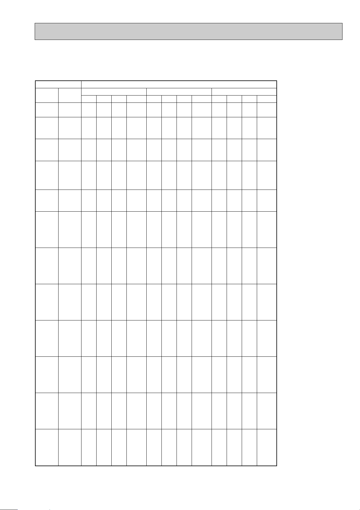
PERFORMANCE DATA
COOLING operation(220V)
SLH-1AR
CAPACITY : 2.5 kW INPUT : 970 W SHF : 0.75
8
Page 9

PERFORMANCE DATA
COOLING operation(220V)
SLH-1AR
CAPACITY : 2.5 kW INPUT : 970 W SHF : 0.75
INDOOR INDOOR
D.B.(;) W.B.(;)
21
21
22
22
22
23
23
23
24
24
24
24
25
25
25
26
26
26
26
26
27
27
27
27
27
28
28
28
28
28
29
29
29
29
29
30
30
30
30
30
31
31
31
31
31
32
32
32
32
32
18
20
18
20
22
18
20
22
18
20
22
24
20
22
24
18
20
22
24
26
18
20
22
24
26
18
20
22
24
26
18
20
22
24
26
18
20
22
24
26
18
20
22
24
26
18
20
22
24
26
Q SHC SHF INPUT Q SHC SHF INPUT Q SHC SHF INPUT
2.45
2.58
2.45
2.58
2.73
2.45
2.58
2.73
2.45
2.58
2.73
2.88
2.58
2.73
2.88
2.45
2.58
2.73
2.88
3.03
2.45
2.58
2.73
2.88
3.03
2.45
2.58
2.73
2.88
3.03
2.45
2.58
2.73
2.88
3.03
2.45
2.58
2.73
2.88
3.03
2.45
2.58
2.73
2.88
3.03
2.45
2.58
2.73
2.88
3.03
35 40 46
1.40
1.16
1.49
1.26
1.01
1.59
1.36
1.12
1.69
1.47
1.23
0.95
1.57
1.34
1.06
1.89
1.67
1.44
1.18
0.88
1.98
1.78
1.55
1.29
1.00
2.08
1.88
1.66
1.41
1.12
2.18
1.98
1.77
1.52
1.24
2.28
2.09
1.88
1.64
1.36
2.38
2.19
1.99
1.75
1.48
2.47
2.29
2.10
1.87
1.60
0.57
0.45
0.61
0.49
0.37
0.65
0.53
0.41
0.69
0.57
0.45
0.33
0.61
0.49
0.37
0.77
0.65
0.53
0.41
0.29
0.81
0.69
0.57
0.45
0.33
0.85
0.73
0.61
0.49
0.37
0.89
0.77
0.65
0.53
0.41
0.93
0.81
0.69
0.57
0.45
0.97
0.85
0.73
0.61
0.49
1.01
0.89
0.77
0.65
0.53
1028
1028
1028
1067
1028
1067
1028
1067
1106
1028
1067
1106
1028
1067
1106
1028
1067
1106
1028
1067
1106
1028
1067
1106
1028
1067
1106
951
989
951
989
951
989
951
989
989
951
989
951
989
951
989
951
989
951
989
951
989
951
989
2.25
2.40
2.25
2.40
2.55
2.25
2.40
2.55
2.25
2.40
2.55
2.70
2.40
2.55
2.70
2.25
2.40
2.55
2.70
2.85
2.25
2.40
2.55
2.70
2.85
2.25
2.40
2.55
2.70
2.85
2.25
2.40
2.55
2.70
2.85
2.25
2.40
2.55
2.70
2.85
2.25
2.40
2.55
2.70
2.85
2.25
2.40
2.55
2.70
2.85
OUTDOOR D.B.(;)
1.28
1.08
1.37
1.18
0.94
1.46
1.27
1.05
1.55
1.37
1.15
0.89
1.46
1.25
1.00
1.73
1.56
1.35
1.11
0.83
1.82
1.66
1.45
1.22
0.94
1.91
1.75
1.56
1.32
1.05
2.00
1.85
1.66
1.43
1.17
2.09
1.94
1.76
1.54
1.28
2.18
2.04
1.86
1.65
1.40
2.27
2.14
1.96
1.76
1.51
0.57
0.45
0.61
0.49
0.37
0.65
0.53
0.41
0.69
0.57
0.45
0.33
0.61
0.49
0.37
0.77
0.65
0.53
0.41
0.29
0.81
0.69
0.57
0.45
0.33
0.85
0.73
0.61
0.49
0.37
0.89
0.77
0.65
0.53
0.41
0.93
0.81
0.69
0.57
0.45
0.97
0.85
0.73
0.61
0.49
1.01
0.89
0.77
0.65
0.53
1009
1038
1009
1038
1086
1009
1038
1086
1009
1038
1086
1116
1038
1086
1116
1009
1038
1086
1116
1154
1009
1038
1086
1116
1154
1009
1038
1086
1116
1154
1009
1038
1086
1116
1154
1009
1038
1086
1116
1154
1009
1038
1086
1116
1154
1009
1038
1086
1116
1154
2.08
2.23
2.08
2.23
2.38
2.08
2.23
2.38
2.08
2.23
2.38
2.55
2.23
2.38
2.55
2.08
2.23
2.38
2.55
2.68
2.08
2.23
2.38
2.55
2.68
2.08
2.23
2.38
2.55
2.68
2.08
2.23
2.38
2.55
2.68
2.08
2.23
2.38
2.55
2.68
2.08
2.23
2.38
2.55
2.68
2.08
2.23
2.38
2.55
2.68
1.18
1.00
1.27
1.09
0.88
1.35
1.18
0.97
1.43
1.27
1.07
0.84
1.36
1.16
0.94
1.60
1.45
1.26
1.05
0.78
1.68
1.54
1.35
1.15
0.88
1.76
1.62
1.45
1.25
0.99
1.85
1.71
1.54
1.35
1.10
1.93
1.80
1.64
1.45
1.20
2.01
1.89
1.73
1.56
1.31
2.10
1.98
1.83
1.66
1.42
0.57
0.45
0.61
0.49
0.37
0.65
0.53
0.41
0.69
0.57
0.45
0.33
0.61
0.49
0.37
0.77
0.65
0.53
0.41
0.29
0.81
0.69
0.57
0.45
0.33
0.85
0.73
0.61
0.49
0.37
0.89
0.77
0.65
0.53
0.41
0.93
0.81
0.69
0.57
0.45
0.97
0.85
0.73
0.61
0.49
1.01
0.89
0.77
0.65
0.53
1048
1096
1048
1096
1125
1048
1096
1125
1048
1096
1125
1164
1096
1125
1164
1048
1096
1125
1164
1203
1048
1096
1125
1164
1203
1048
1096
1125
1164
1203
1048
1096
1125
1164
1203
1048
1096
1125
1164
1203
1048
1096
1125
1164
1203
1048
1096
1125
1164
1203
9
Page 10
OUTDOOR D.B.(;)
INDOOR INDOOR
21 25 27 30
D.B.(;) W.B.(;)
Q SHC SHF INPUT Q SHC SHF INPUT Q SHC SHF INPUT Q SHC SHF INPUT
21
21
22
22
22
23
23
23
24
24
24
24
25
25
25
26
26
26
26
26
27
27
27
27
27
28
28
28
28
28
29
29
29
29
29
30
30
30
30
30
31
31
31
31
31
32
32
32
32
32
18
20
18
20
22
18
20
22
18
20
22
24
20
22
24
18
20
22
24
26
18
20
22
24
26
18
20
22
24
26
18
20
22
24
26
18
20
22
24
26
18
20
22
24
26
18
20
22
24
26
2.94
3.06
2.94
3.06
3.19
2.94
3.06
3.19
2.94
3.06
3.19
3.35
3.06
3.19
3.35
2.94
3.06
3.19
3.35
3.45
2.94
3.06
3.19
3.35
3.45
2.94
3.06
3.19
3.35
3.45
2.94
3.06
3.19
3.35
3.45
2.94
3.06
3.19
3.35
3.45
2.94
3.06
3.19
3.35
3.45
2.94
3.06
3.19
3.35
3.45
0.57
0.45
0.61
0.49
0.37
0.65
0.53
0.41
0.69
0.57
0.45
0.33
0.61
0.49
0.37
0.77
0.65
0.53
0.41
0.29
0.81
0.69
0.57
0.45
0.33
0.85
0.73
0.61
0.49
0.37
0.89
0.77
0.65
0.53
0.41
0.93
0.81
0.69
0.57
0.45
0.97
0.85
0.73
0.61
0.49
1.01
0.89
0.77
0.65
0.53
808
848
808
848
879
808
848
879
808
848
879
919
848
879
919
808
848
879
919
970
808
848
879
919
970
808
848
879
919
970
808
848
879
919
970
808
848
879
919
970
808
848
879
919
970
808
848
879
919
970
1.67
1.38
1.79
1.50
1.18
1.91
1.62
1.31
2.03
1.75
1.43
1.11
1.87
1.56
1.24
2.26
1.99
1.69
1.37
1.00
2.38
2.11
1.82
1.51
1.14
2.50
2.24
1.94
1.64
1.28
2.61
2.36
2.07
1.78
1.41
2.73
2.48
2.20
1.91
1.55
2.85
2.60
2.33
2.04
1.69
2.97
2.73
2.45
2.18
1.83
2.81
2.94
2.81
2.94
3.08
2.81
2.94
3.08
2.81
2.94
3.08
3.23
2.94
3.08
3.23
2.81
2.94
3.08
3.23
3.35
2.81
2.94
3.08
3.23
3.35
2.81
2.94
3.08
3.23
3.35
2.81
2.94
3.08
3.23
3.35
2.81
2.94
3.08
3.23
3.35
2.81
2.94
3.08
3.23
3.35
2.81
2.94
3.08
3.23
3.35
0.57
0.45
0.61
0.49
0.37
0.65
0.53
0.41
0.69
0.57
0.45
0.33
0.61
0.49
0.37
0.77
0.65
0.53
0.41
0.29
0.81
0.69
0.57
0.45
0.33
0.85
0.73
0.61
0.49
0.37
0.89
0.77
0.65
0.53
0.41
0.93
0.81
0.69
0.57
0.45
0.97
0.85
0.73
0.61
0.49
1.01
0.89
0.77
0.65
0.53
848
899
848
899
934
848
899
934
848
899
934
970
899
934
970
848
899
934
970
1020
848
899
934
970
1020
848
899
934
970
1020
848
899
934
970
1020
848
899
934
970
1020
848
899
934
970
1020
848
899
934
970
1020
1.60
1.32
1.72
1.44
1.14
1.83
1.56
1.26
1.94
1.67
1.38
1.06
1.79
1.51
1.19
2.17
1.91
1.63
1.32
0.97
2.28
2.03
1.75
1.45
1.11
2.39
2.14
1.88
1.58
1.24
2.50
2.26
2.00
1.71
1.37
2.62
2.38
2.12
1.84
1.51
2.73
2.50
2.24
1.97
1.64
2.84
2.61
2.37
2.10
1.78
2.70
2.85
2.70
2.85
3.00
2.70
2.85
3.00
2.70
2.85
3.00
3.15
2.85
3.00
3.15
2.70
2.85
3.00
3.15
3.30
2.70
2.85
3.00
3.15
3.30
2.70
2.85
3.00
3.15
3.30
2.70
2.85
3.00
3.15
3.30
2.70
2.85
3.00
3.15
3.30
2.70
2.85
3.00
3.15
3.30
2.70
2.85
3.00
3.15
3.30
0.57
0.45
0.61
0.49
0.37
0.65
0.53
0.41
0.69
0.57
0.45
0.33
0.61
0.49
0.37
0.77
0.65
0.53
0.41
0.29
0.81
0.69
0.57
0.45
0.33
0.85
0.73
0.61
0.49
0.37
0.89
0.77
0.65
0.53
0.41
0.93
0.81
0.69
0.57
0.45
0.97
0.85
0.73
0.61
0.49
1.01
0.89
0.77
0.65
0.53
889
919
889
919
960
889
919
960
889
919
960
1000
919
960
1000
889
919
960
1000
1050
889
919
960
1000
1050
889
919
960
1000
1050
889
919
960
1000
1050
889
919
960
1000
1050
889
919
960
1000
1050
889
919
960
1000
1050
1.54
1.28
1.65
1.40
1.11
1.76
1.51
1.23
1.86
1.62
1.35
1.04
1.74
1.47
1.17
2.08
1.85
1.59
1.29
0.96
2.19
1.97
1.71
1.42
1.09
2.30
2.08
1.83
1.54
1.22
2.40
2.19
1.95
1.67
1.35
2.51
2.31
2.07
1.80
1.49
2.62
2.42
2.19
1.92
1.62
2.73
2.54
2.31
2.05
1.75
2.60
2.75
2.60
2.75
2.88
2.60
2.75
2.88
2.60
2.75
2.88
3.05
2.75
2.88
3.05
2.60
2.75
2.88
3.05
3.20
2.60
2.75
2.88
3.05
3.20
2.60
2.75
2.88
3.05
3.20
2.60
2.75
2.88
3.05
3.20
2.60
2.75
2.88
3.05
3.20
2.60
2.75
2.88
3.05
3.20
2.60
2.75
2.88
3.05
3.20
0.57
0.45
0.61
0.49
0.37
0.65
0.53
0.41
0.69
0.57
0.45
0.33
0.61
0.49
0.37
0.77
0.65
0.53
0.41
0.29
0.81
0.69
0.57
0.45
0.33
0.85
0.73
0.61
0.49
0.37
0.89
0.77
0.65
0.53
0.41
0.93
0.81
0.69
0.57
0.45
0.97
0.85
0.73
0.61
0.49
1.01
0.89
0.77
0.65
0.53
929
960
929
960
1000
929
960
1000
929
960
1000
1050
960
1000
1050
929
960
1000
1050
1081
929
960
1000
1050
1081
929
960
1000
1050
1081
929
960
1000
1050
1081
929
960
1000
1050
1081
929
960
1000
1050
1081
929
960
1000
1050
1081
1.48
1.24
1.59
1.35
1.06
1.69
1.46
1.18
1.79
1.57
1.29
1.01
1.68
1.41
1.13
2.00
1.79
1.52
1.25
0.93
2.11
1.90
1.64
1.37
1.06
2.21
2.01
1.75
1.49
1.18
2.31
2.12
1.87
1.62
1.31
2.42
2.23
1.98
1.74
1.44
2.52
2.34
2.10
1.86
1.57
2.63
2.45
2.21
1.98
1.70
PERFORMANCE DATA
COOLING operation(240V)
SLH-1AR
CAPACITY : 2.5 kW INPUT : 1010 W SHF : 0.75
10
Page 11

PERFORMANCE DATA
COOLING operation(240V)
SLH-1AR
CAPACITY : 2.5 kW INPUT : 1010 W SHF : 0.75
INDOOR INDOOR
D.B.(;) W.B.(;)
21
21
22
22
22
23
23
23
24
24
24
24
25
25
25
26
26
26
26
26
27
27
27
27
27
28
28
28
28
28
29
29
29
29
29
30
30
30
30
30
31
31
31
31
31
32
32
32
32
32
18
20
18
20
22
18
20
22
18
20
22
24
20
22
24
18
20
22
24
26
18
20
22
24
26
18
20
22
24
26
18
20
22
24
26
18
20
22
24
26
18
20
22
24
26
18
20
22
24
26
Q SHC SHF INPUT Q SHC SHF INPUT Q SHC SHF INPUT
2.45
2.58
2.45
2.58
2.73
2.45
2.58
2.73
2.45
2.58
2.73
2.88
2.58
2.73
2.88
2.45
2.58
2.73
2.88
3.03
2.45
2.58
2.73
2.88
3.03
2.45
2.58
2.73
2.88
3.03
2.45
2.58
2.73
2.88
3.03
2.45
2.58
2.73
2.88
3.03
2.45
2.58
2.73
2.88
3.03
2.45
2.58
2.73
2.88
3.03
35 40 46
1.40
1.16
1.49
1.26
1.01
1.59
1.36
1.12
1.69
1.47
1.23
0.95
1.57
1.34
1.06
1.89
1.67
1.44
1.18
0.88
1.98
1.78
1.55
1.29
1.00
2.08
1.88
1.66
1.41
1.12
2.18
1.98
1.77
1.52
1.24
2.28
2.09
1.88
1.64
1.36
2.38
2.19
1.99
1.75
1.48
2.47
2.29
2.10
1.87
1.60
0.57
0.45
0.61
0.49
0.37
0.65
0.53
0.41
0.69
0.57
0.45
0.33
0.61
0.49
0.37
0.77
0.65
0.53
0.41
0.29
0.81
0.69
0.57
0.45
0.33
0.85
0.73
0.61
0.49
0.37
0.89
0.77
0.65
0.53
0.41
0.93
0.81
0.69
0.57
0.45
0.97
0.85
0.73
0.61
0.49
1.01
0.89
0.77
0.65
0.53
990
1030
990
1030
1071
990
1030
1071
990
1030
1071
1111
1030
1071
1111
990
1030
1071
1111
1151
990
1030
1071
1111
1151
990
1030
1071
1111
1151
990
1030
1071
1111
1151
990
1030
1071
1111
1151
990
1030
1071
1111
1151
990
1030
1071
1111
1151
2.25
2.40
2.25
2.40
2.55
2.25
2.40
2.55
2.25
2.40
2.55
2.70
2.40
2.55
2.70
2.25
2.40
2.55
2.70
2.85
2.25
2.40
2.55
2.70
2.85
2.25
2.40
2.55
2.70
2.85
2.25
2.40
2.55
2.70
2.85
2.25
2.40
2.55
2.70
2.85
2.25
2.40
2.55
2.70
2.85
2.25
2.40
2.55
2.70
2.85
OUTDOOR D.B.(;)
1.28
1.08
1.37
1.18
0.94
1.46
1.27
1.05
1.55
1.37
1.15
0.89
1.46
1.25
1.00
1.73
1.56
1.35
1.11
0.83
1.82
1.66
1.45
1.22
0.94
1.91
1.75
1.56
1.32
1.05
2.00
1.85
1.66
1.43
1.17
2.09
1.94
1.76
1.54
1.28
2.18
2.04
1.86
1.65
1.40
2.27
2.14
1.96
1.76
1.51
0.57
0.45
0.61
0.49
0.37
0.65
0.53
0.41
0.69
0.57
0.45
0.33
0.61
0.49
0.37
0.77
0.65
0.53
0.41
0.29
0.81
0.69
0.57
0.45
0.33
0.85
0.73
0.61
0.49
0.37
0.89
0.77
0.65
0.53
0.41
0.93
0.81
0.69
0.57
0.45
0.97
0.85
0.73
0.61
0.49
1.01
0.89
0.77
0.65
0.53
1050
1081
1050
1081
1131
1050
1081
1131
1050
1081
1131
1162
1081
1131
1162
1050
1081
1131
1162
1202
1050
1081
1131
1162
1202
1050
1081
1131
1162
1202
1050
1081
1131
1162
1202
1050
1081
1131
1162
1202
1050
1081
1131
1162
1202
1050
1081
1131
1162
1202
2.08
2.23
2.08
2.23
2.38
2.08
2.23
2.38
2.08
2.23
2.38
2.55
2.23
2.38
2.55
2.08
2.23
2.38
2.55
2.68
2.08
2.23
2.38
2.55
2.68
2.08
2.23
2.38
2.55
2.68
2.08
2.23
2.38
2.55
2.68
2.08
2.23
2.38
2.55
2.68
2.08
2.23
2.38
2.55
2.68
2.08
2.23
2.38
2.55
2.68
1.18
1.00
1.27
1.09
0.88
1.35
1.18
0.97
1.43
1.27
1.07
0.84
1.36
1.16
0.94
1.60
1.45
1.26
1.05
0.78
1.68
1.54
1.35
1.15
0.88
1.76
1.62
1.45
1.25
0.99
1.85
1.71
1.54
1.35
1.10
1.93
1.80
1.64
1.45
1.20
2.01
1.89
1.73
1.56
1.31
2.10
1.98
1.83
1.66
1.42
0.57
0.45
0.61
0.49
0.37
0.65
0.53
0.41
0.69
0.57
0.45
0.33
0.61
0.49
0.37
0.77
0.65
0.53
0.41
0.29
0.81
0.69
0.57
0.45
0.33
0.85
0.73
0.61
0.49
0.37
0.89
0.77
0.65
0.53
0.41
0.93
0.81
0.69
0.57
0.45
0.97
0.85
0.73
0.61
0.49
1.01
0.89
0.77
0.65
0.53
1091
1141
1091
1141
1172
1091
1141
1172
1091
1141
1172
1212
1141
1172
1212
1091
1141
1172
1212
1252
1091
1141
1172
1212
1252
1091
1141
1172
1212
1252
1091
1141
1172
1212
1252
1091
1141
1172
1212
1252
1091
1141
1172
1212
1252
1091
1141
1172
1212
1252
11
Page 12

OUTDOOR D.B.(;)
INDOOR INDOOR
21 25 27 30
D.B.(;) W.B.(;)
Q SHC SHF INPUT Q SHC SHF INPUT Q SHC SHF INPUT Q SHC SHF INPUT
21
21
22
22
22
23
23
23
24
24
24
24
25
25
25
26
26
26
26
26
27
27
27
27
27
28
28
28
28
28
29
29
29
29
29
30
30
30
30
30
31
31
31
31
31
32
32
32
32
32
18
20
18
20
22
18
20
22
18
20
22
24
20
22
24
18
20
22
24
26
18
20
22
24
26
18
20
22
24
26
18
20
22
24
26
18
20
22
24
26
18
20
22
24
26
18
20
22
24
26
4.70
4.90
4.70
4.90
5.10
4.70
4.90
5.10
4.70
4.90
5.10
5.36
4.90
5.10
5.36
4.70
4.90
5.10
5.36
5.52
4.70
4.90
5.10
5.36
5.52
4.70
4.90
5.10
5.36
5.52
4.70
4.90
5.10
5.36
5.52
4.70
4.90
5.10
5.36
5.52
4.70
4.90
5.10
5.36
5.52
4.70
4.90
5.10
5.36
5.52
0.51
0.39
0.55
0.43
0.31
0.59
0.47
0.35
0.63
0.51
0.39
0.27
0.55
0.43
0.31
0.71
0.59
0.47
0.35
0.23
0.75
0.63
0.51
0.39
0.27
0.79
0.67
0.55
0.43
0.31
0.83
0.71
0.59
0.47
0.35
0.87
0.75
0.63
0.51
0.39
0.91
0.79
0.67
0.55
0.43
0.95
0.83
0.71
0.59
0.47
1280
1344
1280
1344
1392
1280
1344
1392
1280
1344
1392
1456
1344
1392
1456
1280
1344
1392
1456
1536
1280
1344
1392
1456
1536
1280
1344
1392
1456
1536
1280
1344
1392
1456
1536
1280
1344
1392
1456
1536
1280
1344
1392
1456
1536
1280
1344
1392
1456
1536
2.40
1.91
2.59
2.11
1.58
2.77
2.30
1.79
2.96
2.50
1.99
1.45
2.70
2.19
1.66
3.34
2.89
2.40
1.88
1.27
3.53
3.09
2.60
2.09
1.49
3.71
3.28
2.81
2.30
1.71
3.90
3.48
3.01
2.52
1.93
4.09
3.68
3.21
2.73
2.15
4.28
3.87
3.42
2.95
2.37
4.47
4.07
3.62
3.16
2.59
4.50
4.70
4.50
4.70
4.92
4.50
4.70
4.92
4.50
4.70
4.92
5.16
4.70
4.92
5.16
4.50
4.70
4.92
5.16
5.36
4.50
4.70
4.92
5.16
5.36
4.50
4.70
4.92
5.16
5.36
4.50
4.70
4.92
5.16
5.36
4.50
4.70
4.92
5.16
5.36
4.50
4.70
4.92
5.16
5.36
4.50
4.70
4.92
5.16
5.36
0.51
0.39
0.55
0.43
0.31
0.59
0.47
0.35
0.63
0.51
0.39
0.27
0.55
0.43
0.31
0.71
0.59
0.47
0.35
0.23
0.75
0.63
0.51
0.39
0.27
0.79
0.67
0.55
0.43
0.31
0.83
0.71
0.59
0.47
0.35
0.87
0.75
0.63
0.51
0.39
0.91
0.79
0.67
0.55
0.43
0.95
0.83
0.71
0.59
0.47
1344
1424
1344
1424
1480
1344
1424
1480
1344
1424
1480
1536
1424
1480
1536
1344
1424
1480
1536
1616
1344
1424
1480
1536
1616
1344
1424
1480
1536
1616
1344
1424
1480
1536
1616
1344
1424
1480
1536
1616
1344
1424
1480
1536
1616
1344
1424
1480
1536
1616
2.30
1.83
2.48
2.02
1.53
2.66
2.21
1.72
2.84
2.40
1.92
1.39
2.59
2.12
1.60
3.20
2.77
2.31
1.81
1.23
3.38
2.96
2.51
2.01
1.45
3.56
3.15
2.71
2.22
1.66
3.74
3.34
2.90
2.43
1.88
3.92
3.53
3.10
2.63
2.09
4.10
3.71
3.30
2.84
2.30
4.28
3.90
3.49
3.04
2.52
4.32
4.56
4.32
4.56
4.80
4.32
4.56
4.80
4.32
4.56
4.80
5.04
4.56
4.80
5.04
4.32
4.56
4.80
5.04
5.28
4.32
4.56
4.80
5.04
5.28
4.32
4.56
4.80
5.04
5.28
4.32
4.56
4.80
5.04
5.28
4.32
4.56
4.80
5.04
5.28
4.32
4.56
4.80
5.04
5.28
4.32
4.56
4.80
5.04
5.28
0.51
0.39
0.55
0.43
0.31
0.59
0.47
0.35
0.63
0.51
0.39
0.27
0.55
0.43
0.31
0.71
0.59
0.47
0.35
0.23
0.75
0.63
0.51
0.39
0.27
0.79
0.67
0.55
0.43
0.31
0.83
0.71
0.59
0.47
0.35
0.87
0.75
0.63
0.51
0.39
0.91
0.79
0.67
0.55
0.43
0.95
0.83
0.71
0.59
0.47
1408
1456
1408
1456
1520
1408
1456
1520
1408
1456
1520
1584
1456
1520
1584
1408
1456
1520
1584
1664
1408
1456
1520
1584
1664
1408
1456
1520
1584
1664
1408
1456
1520
1584
1664
1408
1456
1520
1584
1664
1408
1456
1520
1584
1664
1408
1456
1520
1584
1664
2.20
1.78
2.38
1.96
1.49
2.55
2.14
1.68
2.72
2.33
1.87
1.36
2.51
2.06
1.56
3.07
2.69
2.26
1.76
1.21
3.24
2.87
2.45
1.97
1.43
3.41
3.06
2.64
2.17
1.64
3.59
3.24
2.83
2.37
1.85
3.76
3.42
3.02
2.57
2.06
3.93
3.60
3.22
2.77
2.27
4.10
3.78
3.41
2.97
2.48
4.16
4.40
4.16
4.40
4.60
4.16
4.40
4.60
4.16
4.40
4.60
4.88
4.40
4.60
4.88
4.16
4.40
4.60
4.88
5.12
4.16
4.40
4.60
4.88
5.12
4.16
4.40
4.60
4.88
5.12
4.16
4.40
4.60
4.88
5.12
4.16
4.40
4.60
4.88
5.12
4.16
4.40
4.60
4.88
5.12
4.16
4.40
4.60
4.88
5.12
0.51
0.39
0.55
0.43
0.31
0.59
0.47
0.35
0.63
0.51
0.39
0.27
0.55
0.43
0.31
0.71
0.59
0.47
0.35
0.23
0.75
0.63
0.51
0.39
0.27
0.79
0.67
0.55
0.43
0.31
0.83
0.71
0.59
0.47
0.35
0.87
0.75
0.63
0.51
0.39
0.91
0.79
0.67
0.55
0.43
0.95
0.83
0.71
0.59
0.47
1472
1520
1472
1520
1584
1472
1520
1584
1472
1520
1584
1664
1520
1584
1664
1472
1520
1584
1664
1712
1472
1520
1584
1664
1712
1472
1520
1584
1664
1712
1472
1520
1584
1664
1712
1472
1520
1584
1664
1712
1472
1520
1584
1664
1712
1472
1520
1584
1664
1712
2.12
1.72
2.29
1.89
1.43
2.45
2.07
1.61
2.62
2.24
1.79
1.32
2.42
1.98
1.51
2.95
2.60
2.16
1.71
1.18
3.12
2.77
2.35
1.90
1.38
3.29
2.95
2.53
2.10
1.59
3.45
3.12
2.71
2.29
1.79
3.62
3.30
2.90
2.49
2.00
3.79
3.48
3.08
2.68
2.20
3.95
3.65
3.27
2.88
2.41
PERFORMANCE DATA
COOLING operation(220V)
SLH-1.6AR
CAPACITY : 4.0 kW INPUT : 1600 W SHF : 0.69
12
Page 13
PERFORMANCE DATA
COOLING operation(220V)
SLH-1.6AR
CAPACITY : 4.0 kW INPUT : 1600 W SHF : 0.69
INDOOR INDOOR
D.B.(;) W.B.(;)
21
21
22
22
22
23
23
23
24
24
24
24
25
25
25
26
26
26
26
26
27
27
27
27
27
28
28
28
28
28
29
29
29
29
29
30
30
30
30
30
31
31
31
31
31
32
32
32
32
32
18
20
18
20
22
18
20
22
18
20
22
24
20
22
24
18
20
22
24
26
18
20
22
24
26
18
20
22
24
26
18
20
22
24
26
18
20
22
24
26
18
20
22
24
26
18
20
22
24
26
Q SHC SHF INPUT Q SHC SHF INPUT Q SHC SHF INPUT
3.92
4.12
3.92
4.12
4.36
3.92
4.12
4.36
3.92
4.12
4.36
4.60
4.12
4.36
4.60
3.92
4.12
4.36
4.60
4.84
3.92
4.12
4.36
4.60
4.84
3.92
4.12
4.36
4.60
4.84
3.92
4.12
4.36
4.60
4.84
3.92
4.12
4.36
4.60
4.84
3.92
4.12
4.36
4.60
4.84
3.92
4.12
4.36
4.60
4.84
35 40 46
2.00
1.61
2.16
1.77
1.35
2.31
1.94
1.53
2.47
2.10
1.70
1.24
2.27
1.87
1.43
2.78
2.43
2.05
1.61
1.11
2.94
2.60
2.22
1.79
1.31
3.10
2.76
2.40
1.98
1.50
3.25
2.93
2.57
2.16
1.69
3.41
3.09
2.75
2.35
1.89
3.57
3.25
2.92
2.53
2.08
3.72
3.42
3.10
2.71
2.27
0.51
0.39
0.55
0.43
0.31
0.59
0.47
0.35
0.63
0.51
0.39
0.27
0.55
0.43
0.31
0.71
0.59
0.47
0.35
0.23
0.75
0.63
0.51
0.39
0.27
0.79
0.67
0.55
0.43
0.31
0.83
0.71
0.59
0.47
0.35
0.87
0.75
0.63
0.51
0.39
0.91
0.79
0.67
0.55
0.43
0.95
0.83
0.71
0.59
0.47
1568
1632
1568
1632
1696
1568
1632
1696
1568
1632
1696
1760
1632
1696
1760
1568
1632
1696
1760
1824
1568
1632
1696
1760
1824
1568
1632
1696
1760
1824
1568
1632
1696
1760
1824
1568
1632
1696
1760
1824
1568
1632
1696
1760
1824
1568
1632
1696
1760
1824
3.60
3.84
3.60
3.84
4.08
3.60
3.84
4.08
3.60
3.84
4.08
4.32
3.84
4.08
4.32
3.60
3.84
4.08
4.32
4.56
3.60
3.84
4.08
4.32
4.56
3.60
3.84
4.08
4.32
4.56
3.60
3.84
4.08
4.32
4.56
3.60
3.84
4.08
4.32
4.56
3.60
3.84
4.08
4.32
4.56
3.60
3.84
4.08
4.32
4.56
OUTDOOR D.B.(;)
1.84
1.50
1.98
1.65
1.26
2.12
1.80
1.43
2.27
1.96
1.59
1.17
2.11
1.75
1.34
2.56
2.27
1.92
1.51
1.05
2.70
2.42
2.08
1.68
1.23
2.84
2.57
2.24
1.86
1.41
2.99
2.73
2.41
2.03
1.60
3.13
2.88
2.57
2.20
1.78
3.28
3.03
2.73
2.38
1.96
3.42
3.19
2.90
2.55
2.14
0.51
0.39
0.55
0.43
0.31
0.59
0.47
0.35
0.63
0.51
0.39
0.27
0.55
0.43
0.31
0.71
0.59
0.47
0.35
0.23
0.75
0.63
0.51
0.39
0.27
0.79
0.67
0.55
0.43
0.31
0.83
0.71
0.59
0.47
0.35
0.87
0.75
0.63
0.51
0.39
0.91
0.79
0.67
0.55
0.43
0.95
0.83
0.71
0.59
0.47
1664
1712
1664
1712
1792
1664
1712
1792
1664
1712
1792
1840
1712
1792
1840
1664
1712
1792
1840
1904
1664
1712
1792
1840
1904
1664
1712
1792
1840
1904
1664
1712
1792
1840
1904
1664
1712
1792
1840
1904
1664
1712
1792
1840
1904
1664
1712
1792
1840
1904
3.32
3.56
3.32
3.56
3.80
3.32
3.56
3.80
3.32
3.56
3.80
4.08
3.56
3.80
4.08
3.32
3.56
3.80
4.08
4.28
3.32
3.56
3.80
4.08
4.28
3.32
3.56
3.80
4.08
4.28
3.32
3.56
3.80
4.08
4.28
3.32
3.56
3.80
4.08
4.28
3.32
3.56
3.80
4.08
4.28
3.32
3.56
3.80
4.08
4.28
1.69
1.39
1.83
1.53
1.18
1.96
1.67
1.33
2.09
1.82
1.48
1.10
1.96
1.63
1.26
2.36
2.10
1.79
1.43
0.98
2.49
2.24
1.94
1.59
1.16
2.62
2.39
2.09
1.75
1.33
2.76
2.53
2.24
1.92
1.50
2.89
2.67
2.39
2.08
1.67
3.02
2.81
2.55
2.24
1.84
3.15
2.95
2.70
2.41
2.01
0.51
0.39
0.55
0.43
0.31
0.59
0.47
0.35
0.63
0.51
0.39
0.27
0.55
0.43
0.31
0.71
0.59
0.47
0.35
0.23
0.75
0.63
0.51
0.39
0.27
0.79
0.67
0.55
0.43
0.31
0.83
0.71
0.59
0.47
0.35
0.87
0.75
0.63
0.51
0.39
0.91
0.79
0.67
0.55
0.43
0.95
0.83
0.71
0.59
0.47
1728
1808
1728
1808
1856
1728
1808
1856
1728
1808
1856
1920
1808
1856
1920
1728
1808
1856
1920
1984
1728
1808
1856
1920
1984
1728
1808
1856
1920
1984
1728
1808
1856
1920
1984
1728
1808
1856
1920
1984
1728
1808
1856
1920
1984
1728
1808
1856
1920
1984
13
Page 14

OUTDOOR D.B.(;)
INDOOR INDOOR
21 25 27 30
D.B.(;) W.B.(;)
Q SHC SHF INPUT Q SHC SHF INPUT Q SHC SHF INPUT Q SHC SHF INPUT
21
21
22
22
22
23
23
23
24
24
24
24
25
25
25
26
26
26
26
26
27
27
27
27
27
28
28
28
28
28
29
29
29
29
29
30
30
30
30
30
31
31
31
31
31
32
32
32
32
32
18
20
18
20
22
18
20
22
18
20
22
24
20
22
24
18
20
22
24
26
18
20
22
24
26
18
20
22
24
26
18
20
22
24
26
18
20
22
24
26
18
20
22
24
26
18
20
22
24
26
4.82
5.02
4.82
5.02
5.23
4.82
5.02
5.23
4.82
5.02
5.23
5.49
5.02
5.23
5.49
4.82
5.02
5.23
5.49
5.66
4.82
5.02
5.23
5.49
5.66
4.82
5.02
5.23
5.49
5.66
4.82
5.02
5.23
5.49
5.66
4.82
5.02
5.23
5.49
5.66
4.82
5.02
5.23
5.49
5.66
4.82
5.02
5.23
5.49
5.66
0.51
0.39
0.55
0.43
0.31
0.59
0.47
0.35
0.63
0.51
0.39
0.27
0.55
0.43
0.31
0.71
0.59
0.47
0.35
0.23
0.75
0.63
0.51
0.39
0.27
0.79
0.67
0.55
0.43
0.31
0.83
0.71
0.59
0.47
0.35
0.87
0.75
0.63
0.51
0.39
0.91
0.79
0.67
0.55
0.43
0.95
0.83
0.71
0.59
0.47
1360
1428
1360
1428
1479
1360
1428
1479
1360
1428
1479
1547
1428
1479
1547
1360
1428
1479
1547
1632
1360
1428
1479
1547
1632
1360
1428
1479
1547
1632
1360
1428
1479
1547
1632
1360
1428
1479
1547
1632
1360
1428
1479
1547
1632
1360
1428
1479
1547
1632
2.46
1.96
2.65
2.16
1.62
2.84
2.36
1.83
3.04
2.56
2.04
1.48
2.76
2.25
1.70
3.42
2.96
2.46
1.92
1.30
3.61
3.16
2.67
2.14
1.53
3.81
3.37
2.88
2.36
1.75
4.00
3.57
3.08
2.58
1.98
4.19
3.77
3.29
2.80
2.21
4.38
3.97
3.50
3.02
2.43
4.58
4.17
3.71
3.24
2.66
4.61
4.82
4.61
4.82
5.04
4.61
4.82
5.04
4.61
4.82
5.04
5.29
4.82
5.04
5.29
4.61
4.82
5.04
5.29
5.49
4.61
4.82
5.04
5.29
5.49
4.61
4.82
5.04
5.29
5.49
4.61
4.82
5.04
5.29
5.49
4.61
4.82
5.04
5.29
5.49
4.61
4.82
5.04
5.29
5.49
4.61
4.82
5.04
5.29
5.49
0.51
0.39
0.55
0.43
0.31
0.59
0.47
0.35
0.63
0.51
0.39
0.27
0.55
0.43
0.31
0.71
0.59
0.47
0.35
0.23
0.75
0.63
0.51
0.39
0.27
0.79
0.67
0.55
0.43
0.31
0.83
0.71
0.59
0.47
0.35
0.87
0.75
0.63
0.51
0.39
0.91
0.79
0.67
0.55
0.43
0.95
0.83
0.71
0.59
0.47
1428
1513
1428
1513
1573
1428
1513
1573
1428
1513
1573
1632
1513
1573
1632
1428
1513
1573
1632
1717
1428
1513
1573
1632
1717
1428
1513
1573
1632
1717
1428
1513
1573
1632
1717
1428
1513
1573
1632
1717
1428
1513
1573
1632
1717
1428
1513
1573
1632
1717
2.35
1.88
2.54
2.07
1.56
2.72
2.26
1.77
2.91
2.46
1.97
1.43
2.65
2.17
1.64
3.27
2.84
2.37
1.85
1.26
3.46
3.04
2.57
2.06
1.48
3.64
3.23
2.77
2.27
1.70
3.83
3.42
2.98
2.49
1.92
4.01
3.61
3.18
2.70
2.14
4.20
3.81
3.38
2.91
2.36
4.38
4.00
3.58
3.12
2.58
4.43
4.67
4.43
4.67
4.92
4.43
4.67
4.92
4.43
4.67
4.92
5.17
4.67
4.92
5.17
4.43
4.67
4.92
5.17
5.41
4.43
4.67
4.92
5.17
5.41
4.43
4.67
4.92
5.17
5.41
4.43
4.67
4.92
5.17
5.41
4.43
4.67
4.92
5.17
5.41
4.43
4.67
4.92
5.17
5.41
4.43
4.67
4.92
5.17
5.41
0.51
0.39
0.55
0.43
0.31
0.59
0.47
0.35
0.63
0.51
0.39
0.27
0.55
0.43
0.31
0.71
0.59
0.47
0.35
0.23
0.75
0.63
0.51
0.39
0.27
0.79
0.67
0.55
0.43
0.31
0.83
0.71
0.59
0.47
0.35
0.87
0.75
0.63
0.51
0.39
0.91
0.79
0.67
0.55
0.43
0.95
0.83
0.71
0.59
0.47
1496
1547
1496
1547
1615
1496
1547
1615
1496
1547
1615
1683
1547
1615
1683
1496
1547
1615
1683
1768
1496
1547
1615
1683
1768
1496
1547
1615
1683
1768
1496
1547
1615
1683
1768
1496
1547
1615
1683
1768
1496
1547
1615
1683
1768
1496
1547
1615
1683
1768
2.26
1.82
2.44
2.01
1.53
2.61
2.20
1.72
2.79
2.38
1.92
1.39
2.57
2.12
1.60
3.14
2.76
2.31
1.81
1.24
3.32
2.94
2.51
2.01
1.46
3.50
3.13
2.71
2.22
1.68
3.68
3.32
2.90
2.43
1.89
3.85
3.51
3.10
2.63
2.11
4.03
3.69
3.30
2.84
2.33
4.21
3.88
3.49
3.05
2.54
4.26
4.51
4.26
4.51
4.72
4.26
4.51
4.72
4.26
4.51
4.72
5.00
4.51
4.72
5.00
4.26
4.51
4.72
5.00
5.25
4.26
4.51
4.72
5.00
5.25
4.26
4.51
4.72
5.00
5.25
4.26
4.51
4.72
5.00
5.25
4.26
4.51
4.72
5.00
5.25
4.26
4.51
4.72
5.00
5.25
4.26
4.51
4.72
5.00
5.25
0.51
0.39
0.55
0.43
0.31
0.59
0.47
0.35
0.63
0.51
0.39
0.27
0.55
0.43
0.31
0.71
0.59
0.47
0.35
0.23
0.75
0.63
0.51
0.39
0.27
0.79
0.67
0.55
0.43
0.31
0.83
0.71
0.59
0.47
0.35
0.87
0.75
0.63
0.51
0.39
0.91
0.79
0.67
0.55
0.43
0.95
0.83
0.71
0.59
0.47
1564
1615
1564
1615
1683
1564
1615
1683
1564
1615
1683
1768
1615
1683
1768
1564
1615
1683
1768
1819
1564
1615
1683
1768
1819
1564
1615
1683
1768
1819
1564
1615
1683
1768
1819
1564
1615
1683
1768
1819
1564
1615
1683
1768
1819
1564
1615
1683
1768
1819
2.17
1.76
2.35
1.94
1.46
2.52
2.12
1.65
2.69
2.30
1.84
1.35
2.48
2.03
1.55
3.03
2.66
2.22
1.75
1.21
3.20
2.84
2.40
1.95
1.42
3.37
3.02
2.59
2.15
1.63
3.54
3.20
2.78
2.35
1.84
3.71
3.38
2.97
2.55
2.05
3.88
3.56
3.16
2.75
2.26
4.05
3.74
3.35
2.95
2.47
PERFORMANCE DATA
COOLING operation(240V)
SLH-1.6AR
CAPACITY : 4.1 kW INPUT : 1700 W SHF : 0.69
14
Page 15

PERFORMANCE DATA
COOLING operation(240V)
SLH-1.6AR
CAPACITY : 4.1 kW INPUT : 1700 W SHF : 0.69
INDOOR INDOOR
D.B.(;) W.B.(;)
21
21
22
22
22
23
23
23
24
24
24
24
25
25
25
26
26
26
26
26
27
27
27
27
27
28
28
28
28
28
29
29
29
29
29
30
30
30
30
30
31
31
31
31
31
32
32
32
32
32
18
20
18
20
22
18
20
22
18
20
22
24
20
22
24
18
20
22
24
26
18
20
22
24
26
18
20
22
24
26
18
20
22
24
26
18
20
22
24
26
18
20
22
24
26
18
20
22
24
26
Q SHC SHF INPUT Q SHC SHF INPUT Q SHC SHF INPUT
4.02
4.22
4.02
4.22
4.47
4.02
4.22
4.47
4.02
4.22
4.47
4.72
4.22
4.47
4.72
4.02
4.22
4.47
4.72
4.96
4.02
4.22
4.47
4.72
4.96
4.02
4.22
4.47
4.72
4.96
4.02
4.22
4.47
4.72
4.96
4.02
4.22
4.47
4.72
4.96
4.02
4.22
4.47
4.72
4.96
4.02
4.22
4.47
4.72
4.96
35 40 46
2.05
1.65
2.21
1.82
1.39
2.37
1.98
1.56
2.53
2.15
1.74
1.27
2.32
1.92
1.46
2.85
2.49
2.10
1.65
1.14
3.01
2.66
2.28
1.84
1.34
3.17
2.83
2.46
2.03
1.54
3.33
3.00
2.64
2.22
1.74
3.50
3.17
2.82
2.40
1.93
3.66
3.34
2.99
2.59
2.13
3.82
3.51
3.17
2.78
2.33
0.51
0.39
0.55
0.43
0.31
0.59
0.47
0.35
0.63
0.51
0.39
0.27
0.55
0.43
0.31
0.71
0.59
0.47
0.35
0.23
0.75
0.63
0.51
0.39
0.27
0.79
0.67
0.55
0.43
0.31
0.83
0.71
0.59
0.47
0.35
0.87
0.75
0.63
0.51
0.39
0.91
0.79
0.67
0.55
0.43
0.95
0.83
0.71
0.59
0.47
1666
1734
1666
1734
1802
1666
1734
1802
1666
1734
1802
1870
1734
1802
1870
1666
1734
1802
1870
1938
1666
1734
1802
1870
1938
1666
1734
1802
1870
1938
1666
1734
1802
1870
1938
1666
1734
1802
1870
1938
1666
1734
1802
1870
1938
1666
1734
1802
1870
1938
3.69
3.94
3.69
3.94
4.18
3.69
3.94
4.18
3.69
3.94
4.18
4.43
3.94
4.18
4.43
3.69
3.94
4.18
4.43
4.67
3.69
3.94
4.18
4.43
4.67
3.69
3.94
4.18
4.43
4.67
3.69
3.94
4.18
4.43
4.67
3.69
3.94
4.18
4.43
4.67
3.69
3.94
4.18
4.43
4.67
3.69
3.94
4.18
4.43
4.67
OUTDOOR D.B.(;)
1.88
1.54
2.03
1.69
1.30
2.18
1.85
1.46
2.32
2.01
1.63
1.20
2.16
1.80
1.37
2.62
2.32
1.97
1.55
1.08
2.77
2.48
2.13
1.73
1.26
2.92
2.64
2.30
1.90
1.45
3.06
2.79
2.47
2.08
1.64
3.21
2.95
2.63
2.26
1.82
3.36
3.11
2.80
2.44
2.01
3.51
3.27
2.97
2.61
2.20
0.51
0.39
0.55
0.43
0.31
0.59
0.47
0.35
0.63
0.51
0.39
0.27
0.55
0.43
0.31
0.71
0.59
0.47
0.35
0.23
0.75
0.63
0.51
0.39
0.27
0.79
0.67
0.55
0.43
0.31
0.83
0.71
0.59
0.47
0.35
0.87
0.75
0.63
0.51
0.39
0.91
0.79
0.67
0.55
0.43
0.95
0.83
0.71
0.59
0.47
1768
1819
1768
1819
1904
1768
1819
1904
1768
1819
1904
1955
1819
1904
1955
1768
1819
1904
1955
2023
1768
1819
1904
1955
2023
1768
1819
1904
1955
2023
1768
1819
1904
1955
2023
1768
1819
1904
1955
2023
1768
1819
1904
1955
2023
1768
1819
1904
1955
2023
3.40
3.65
3.40
3.65
3.90
3.40
3.65
3.90
3.40
3.65
3.90
4.18
3.65
3.90
4.18
3.40
3.65
3.90
4.18
4.39
3.40
3.65
3.90
4.18
4.39
3.40
3.65
3.90
4.18
4.39
3.40
3.65
3.90
4.18
4.39
3.40
3.65
3.90
4.18
4.39
3.40
3.65
3.90
4.18
4.39
3.40
3.65
3.90
4.18
4.39
1.74
1.42
1.87
1.57
1.21
2.01
1.72
1.36
2.14
1.86
1.52
1.13
2.01
1.67
1.30
2.42
2.15
1.83
1.46
1.01
2.55
2.30
1.99
1.63
1.18
2.69
2.44
2.14
1.80
1.36
2.82
2.59
2.30
1.97
1.54
2.96
2.74
2.45
2.13
1.71
3.10
2.88
2.61
2.30
1.89
3.23
3.03
2.77
2.47
2.06
0.51
0.39
0.55
0.43
0.31
0.59
0.47
0.35
0.63
0.51
0.39
0.27
0.55
0.43
0.31
0.71
0.59
0.47
0.35
0.23
0.75
0.63
0.51
0.39
0.27
0.79
0.67
0.55
0.43
0.31
0.83
0.71
0.59
0.47
0.35
0.87
0.75
0.63
0.51
0.39
0.91
0.79
0.67
0.55
0.43
0.95
0.83
0.71
0.59
0.47
1836
1921
1836
1921
1972
1836
1921
1972
1836
1921
1972
2040
1921
1972
2040
1836
1921
1972
2040
2108
1836
1921
1972
2040
2108
1836
1921
1972
2040
2108
1836
1921
1972
2040
2108
1836
1921
1972
2040
2108
1836
1921
1972
2040
2108
1836
1921
1972
2040
2108
15
Page 16

OUTDOOR D.B.(;)
INDOOR INDOOR
21 25 27 30
D.B.(;) W.B.(;)
Q SHC SHF INPUT Q SHC SHF INPUT Q SHC SHF INPUT Q SHC SHF INPUT
21
21
22
22
22
23
23
23
24
24
24
24
25
25
25
26
26
26
26
26
27
27
27
27
27
28
28
28
28
28
29
29
29
29
29
30
30
30
30
30
31
31
31
31
31
32
32
32
32
32
18
20
18
20
22
18
20
22
18
20
22
24
20
22
24
18
20
22
24
26
18
20
22
24
26
18
20
22
24
26
18
20
22
24
26
18
20
22
24
26
18
20
22
24
26
18
20
22
24
26
5.88
6.13
5.88
6.13
6.38
5.88
6.13
6.38
5.88
6.13
6.38
6.70
6.13
6.38
6.70
5.88
6.13
6.38
6.70
6.90
5.88
6.13
6.38
6.70
6.90
5.88
6.13
6.38
6.70
6.90
5.88
6.13
6.38
6.70
6.90
5.88
6.13
6.38
6.70
6.90
5.88
6.13
6.38
6.70
6.90
5.88
6.13
6.38
6.70
6.90
0.46
0.34
0.50
0.38
0.26
0.54
0.42
0.30
0.58
0.46
0.34
0.22
0.50
0.38
0.26
0.66
0.54
0.42
0.30
0.18
0.70
0.58
0.46
0.34
0.22
0.74
0.62
0.50
0.38
0.26
0.78
0.66
0.54
0.42
0.30
0.82
0.70
0.58
0.46
0.34
0.86
0.74
0.62
0.50
0.38
0.90
0.78
0.66
0.54
0.42
1784
1873
1784
1873
1940
1784
1873
1940
1784
1873
1940
2029
1873
1940
2029
1784
1873
1940
2029
2141
1784
1873
1940
2029
2141
1784
1873
1940
2029
2141
1784
1873
1940
2029
2141
1784
1873
1940
2029
2141
1784
1873
1940
2029
2141
1784
1873
1940
2029
2141
2.70
2.08
2.94
2.33
1.66
3.17
2.57
1.91
3.41
2.82
2.17
1.47
3.06
2.42
1.74
3.88
3.31
2.68
2.01
1.24
4.11
3.55
2.93
2.28
1.52
4.35
3.80
3.19
2.55
1.79
4.58
4.04
3.44
2.81
2.07
4.82
4.29
3.70
3.08
2.35
5.05
4.53
3.95
3.35
2.62
5.29
4.78
4.21
3.62
2.90
5.63
5.88
5.63
5.88
6.15
5.63
5.88
6.15
5.63
5.88
6.15
6.45
5.88
6.15
6.45
5.63
5.88
6.15
6.45
6.70
5.63
5.88
6.15
6.45
6.70
5.63
5.88
6.15
6.45
6.70
5.63
5.88
6.15
6.45
6.70
5.63
5.88
6.15
6.45
6.70
5.63
5.88
6.15
6.45
6.70
5.63
5.88
6.15
6.45
6.70
0.46
0.34
0.50
0.38
0.26
0.54
0.42
0.30
0.58
0.46
0.34
0.22
0.50
0.38
0.26
0.66
0.54
0.42
0.30
0.18
0.70
0.58
0.46
0.34
0.22
0.74
0.62
0.50
0.38
0.26
0.78
0.66
0.54
0.42
0.30
0.82
0.70
0.58
0.46
0.34
0.86
0.74
0.62
0.50
0.38
0.90
0.78
0.66
0.54
0.42
1873
1985
1873
1985
2063
1873
1985
2063
1873
1985
2063
2141
1985
2063
2141
1873
1985
2063
2141
2252
1873
1985
2063
2141
2252
1873
1985
2063
2141
2252
1873
1985
2063
2141
2252
1873
1985
2063
2141
2252
1873
1985
2063
2141
2252
1873
1985
2063
2141
2252
2.59
2.00
2.81
2.23
1.60
3.04
2.47
1.85
3.26
2.70
2.09
1.42
2.94
2.34
1.68
3.71
3.17
2.58
1.94
1.21
3.94
3.41
2.83
2.19
1.47
4.16
3.64
3.08
2.45
1.74
4.39
3.88
3.32
2.71
2.01
4.61
4.11
3.57
2.97
2.28
4.84
4.35
3.81
3.23
2.55
5.06
4.58
4.06
3.48
2.81
5.40
5.70
5.40
5.70
6.00
5.40
5.70
6.00
5.40
5.70
6.00
6.30
5.70
6.00
6.30
5.40
5.70
6.00
6.30
6.60
5.40
5.70
6.00
6.30
6.60
5.40
5.70
6.00
6.30
6.60
5.40
5.70
6.00
6.30
6.60
5.40
5.70
6.00
6.30
6.60
5.40
5.70
6.00
6.30
6.60
5.40
5.70
6.00
6.30
6.60
0.46
0.34
0.50
0.38
0.26
0.54
0.42
0.30
0.58
0.46
0.34
0.22
0.50
0.38
0.26
0.66
0.54
0.42
0.30
0.18
0.70
0.58
0.46
0.34
0.22
0.74
0.62
0.50
0.38
0.26
0.78
0.66
0.54
0.42
0.30
0.82
0.70
0.58
0.46
0.34
0.86
0.74
0.62
0.50
0.38
0.90
0.78
0.66
0.54
0.42
1962
2029
1962
2029
2119
1962
2029
2119
1962
2029
2119
2208
2029
2119
2208
1962
2029
2119
2208
2319
1962
2029
2119
2208
2319
1962
2029
2119
2208
2319
1962
2029
2119
2208
2319
1962
2029
2119
2208
2319
1962
2029
2119
2208
2319
1962
2029
2119
2208
2319
2.48
1.94
2.70
2.17
1.56
2.92
2.39
1.80
3.13
2.62
2.04
1.39
2.85
2.28
1.64
3.56
3.08
2.52
1.89
1.19
3.78
3.31
2.76
2.14
1.45
4.00
3.53
3.00
2.39
1.72
4.21
3.76
3.24
2.65
1.98
4.43
3.99
3.48
2.90
2.24
4.64
4.22
3.72
3.15
2.51
4.86
4.45
3.96
3.40
2.77
5.20
5.50
5.20
5.50
5.75
5.20
5.50
5.75
5.20
5.50
5.75
6.10
5.50
5.75
6.10
5.20
5.50
5.75
6.10
6.40
5.20
5.50
5.75
6.10
6.40
5.20
5.50
5.75
6.10
6.40
5.20
5.50
5.75
6.10
6.40
5.20
5.50
5.75
6.10
6.40
5.20
5.50
5.75
6.10
6.40
5.20
5.50
5.75
6.10
6.40
0.46
0.34
0.50
0.38
0.26
0.54
0.42
0.30
0.58
0.46
0.34
0.22
0.50
0.38
0.26
0.66
0.54
0.42
0.30
0.18
0.70
0.58
0.46
0.34
0.22
0.74
0.62
0.50
0.38
0.26
0.78
0.66
0.54
0.42
0.30
0.82
0.70
0.58
0.46
0.34
0.86
0.74
0.62
0.50
0.38
0.90
0.78
0.66
0.54
0.42
2052
2119
2052
2119
2208
2052
2119
2208
2052
2119
2208
2319
2119
2208
2319
2052
2119
2208
2319
2386
2052
2119
2208
2319
2386
2052
2119
2208
2319
2386
2052
2119
2208
2319
2386
2052
2119
2208
2319
2386
2052
2119
2208
2319
2386
2052
2119
2208
2319
2386
2.39
1.87
2.60
2.09
1.50
2.81
2.31
1.73
3.02
2.53
1.96
1.34
2.75
2.19
1.59
3.43
2.97
2.42
1.83
1.15
3.64
3.19
2.65
2.07
1.41
3.85
3.41
2.88
2.32
1.66
4.06
3.63
3.11
2.56
1.92
4.26
3.85
3.34
2.81
2.18
4.47
4.07
3.57
3.05
2.43
4.68
4.29
3.80
3.29
2.69
PERFORMANCE DATA
COOLING operation(220V)
SLH-2AR
CAPACITY : 5.0 kW INPUT : 2230 W SHF : 0.64
16
Page 17

PERFORMANCE DATA
COOLING operation(220V)
SLH-2AR
CAPACITY : 5.0 kW INPUT : 2230 W SHF : 0.64
INDOOR INDOOR
D.B.(;) W.B.(;)
21
21
22
22
22
23
23
23
24
24
24
24
25
25
25
26
26
26
26
26
27
27
27
27
27
28
28
28
28
28
29
29
29
29
29
30
30
30
30
30
31
31
31
31
31
32
32
32
32
32
18
20
18
20
22
18
20
22
18
20
22
24
20
22
24
18
20
22
24
26
18
20
22
24
26
18
20
22
24
26
18
20
22
24
26
18
20
22
24
26
18
20
22
24
26
18
20
22
24
26
Q SHC SHF INPUT Q SHC SHF INPUT Q SHC SHF INPUT
4.90
5.15
4.90
5.15
5.45
4.90
5.15
5.45
4.90
5.15
5.45
5.75
5.15
5.45
5.75
4.90
5.15
5.45
5.75
6.05
4.90
5.15
5.45
5.75
6.05
4.90
5.15
5.45
5.75
6.05
4.90
5.15
5.45
5.75
6.05
4.90
5.15
5.45
5.75
6.05
4.90
5.15
5.45
5.75
6.05
4.90
5.15
5.45
5.75
6.05
35 40 46
2.25
1.75
2.45
1.96
1.42
2.65
2.16
1.64
2.84
2.37
1.85
1.27
2.58
2.07
1.50
3.23
2.78
2.29
1.73
1.09
3.43
2.99
2.51
1.96
1.33
3.63
3.19
2.73
2.19
1.57
3.82
3.40
2.94
2.42
1.82
4.02
3.61
3.16
2.65
2.06
4.21
3.81
3.38
2.88
2.30
4.41
4.02
3.60
3.11
2.54
0.46
0.34
0.50
0.38
0.26
0.54
0.42
0.30
0.58
0.46
0.34
0.22
0.50
0.38
0.26
0.66
0.54
0.42
0.30
0.18
0.70
0.58
0.46
0.34
0.22
0.74
0.62
0.50
0.38
0.26
0.78
0.66
0.54
0.42
0.30
0.82
0.70
0.58
0.46
0.34
0.86
0.74
0.62
0.50
0.38
0.90
0.78
0.66
0.54
0.42
2185
2275
2185
2275
2364
2185
2275
2364
2185
2275
2364
2453
2275
2364
2453
2185
2275
2364
2453
2542
2185
2275
2364
2453
2542
2185
2275
2364
2453
2542
2185
2275
2364
2453
2542
2185
2275
2364
2453
2542
2185
2275
2364
2453
2542
2185
2275
2364
2453
2542
4.50
4.80
4.50
4.80
5.10
4.50
4.80
5.10
4.50
4.80
5.10
5.40
4.80
5.10
5.40
4.50
4.80
5.10
5.40
5.70
4.50
4.80
5.10
5.40
5.70
4.50
4.80
5.10
5.40
5.70
4.50
4.80
5.10
5.40
5.70
4.50
4.80
5.10
5.40
5.70
4.50
4.80
5.10
5.40
5.70
4.50
4.80
5.10
5.40
5.70
OUTDOOR D.B.(;)
2.07
1.63
2.25
1.82
1.33
2.43
2.02
1.53
2.61
2.21
1.73
1.19
2.40
1.94
1.40
2.97
2.59
2.14
1.62
1.03
3.15
2.78
2.35
1.84
1.25
3.33
2.98
2.55
2.05
1.48
3.51
3.17
2.75
2.27
1.71
3.69
3.36
2.96
2.48
1.94
3.87
3.55
3.16
2.70
2.17
4.05
3.74
3.37
2.92
2.39
0.46
0.34
0.50
0.38
0.26
0.54
0.42
0.30
0.58
0.46
0.34
0.22
0.50
0.38
0.26
0.66
0.54
0.42
0.30
0.18
0.70
0.58
0.46
0.34
0.22
0.74
0.62
0.50
0.38
0.26
0.78
0.66
0.54
0.42
0.30
0.82
0.70
0.58
0.46
0.34
0.86
0.74
0.62
0.50
0.38
0.90
0.78
0.66
0.54
0.42
2319
2386
2319
2386
2498
2319
2386
2498
2319
2386
2498
2565
2386
2498
2565
2319
2386
2498
2565
2654
2319
2386
2498
2565
2654
2319
2386
2498
2565
2654
2319
2386
2498
2565
2654
2319
2386
2498
2565
2654
2319
2386
2498
2565
2654
2319
2386
2498
2565
2654
4.15
4.45
4.15
4.45
4.75
4.15
4.45
4.75
4.15
4.45
4.75
5.10
4.45
4.75
5.10
4.15
4.45
4.75
5.10
5.35
4.15
4.45
4.75
5.10
5.35
4.15
4.45
4.75
5.10
5.35
4.15
4.45
4.75
5.10
5.35
4.15
4.45
4.75
5.10
5.35
4.15
4.45
4.75
5.10
5.35
4.15
4.45
4.75
5.10
5.35
1.91
1.51
2.08
1.69
1.24
2.24
1.87
1.43
2.41
2.05
1.62
1.12
2.23
1.81
1.33
2.74
2.40
2.00
1.53
0.96
2.91
2.58
2.19
1.73
1.18
3.07
2.76
2.38
1.94
1.39
3.24
2.94
2.57
2.14
1.61
3.40
3.12
2.76
2.35
1.82
3.57
3.29
2.95
2.55
2.03
3.74
3.47
3.14
2.75
2.25
0.46
0.34
0.50
0.38
0.26
0.54
0.42
0.30
0.58
0.46
0.34
0.22
0.50
0.38
0.26
0.66
0.54
0.42
0.30
0.18
0.70
0.58
0.46
0.34
0.22
0.74
0.62
0.50
0.38
0.26
0.78
0.66
0.54
0.42
0.30
0.82
0.70
0.58
0.46
0.34
0.86
0.74
0.62
0.50
0.38
0.90
0.78
0.66
0.54
0.42
2408
2520
2408
2520
2587
2408
2520
2587
2408
2520
2587
2676
2520
2587
2676
2408
2520
2587
2676
2765
2408
2520
2587
2676
2765
2408
2520
2587
2676
2765
2408
2520
2587
2676
2765
2408
2520
2587
2676
2765
2408
2520
2587
2676
2765
2408
2520
2587
2676
2765
17
Page 18
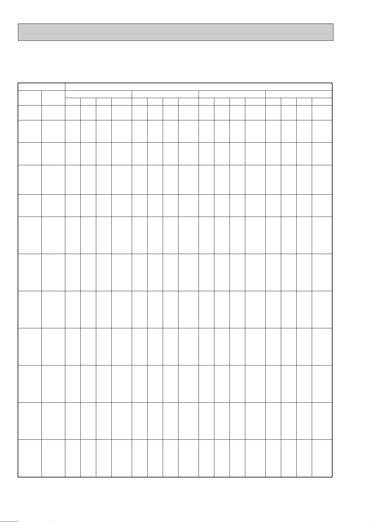
OUTDOOR D.B.(;)
INDOOR INDOOR
21 25 27 30
D.B.(;) W.B.(;)
Q SHC SHF INPUT Q SHC SHF INPUT Q SHC SHF INPUT Q SHC SHF INPUT
21
21
22
22
22
23
23
23
24
24
24
24
25
25
25
26
26
26
26
26
27
27
27
27
27
28
28
28
28
28
29
29
29
29
29
30
30
30
30
30
31
31
31
31
31
32
32
32
32
32
18
20
18
20
22
18
20
22
18
20
22
24
20
22
24
18
20
22
24
26
18
20
22
24
26
18
20
22
24
26
18
20
22
24
26
18
20
22
24
26
18
20
22
24
26
18
20
22
24
26
5.99
6.25
5.99
6.25
6.50
5.99
6.25
6.50
5.99
6.25
6.50
6.83
6.25
6.50
6.83
5.99
6.25
6.50
6.83
7.04
5.99
6.25
6.50
6.83
7.04
5.99
6.25
6.50
6.83
7.04
5.99
6.25
6.50
6.83
7.04
5.99
6.25
6.50
6.83
7.04
5.99
6.25
6.50
6.83
7.04
5.99
6.25
6.50
6.83
7.04
0.46
0.34
0.50
0.38
0.26
0.54
0.42
0.30
0.58
0.46
0.34
0.22
0.50
0.38
0.26
0.66
0.54
0.42
0.30
0.18
0.70
0.58
0.46
0.34
0.22
0.74
0.62
0.50
0.38
0.26
0.78
0.66
0.54
0.42
0.30
0.82
0.70
0.58
0.46
0.34
0.86
0.74
0.62
0.50
0.38
0.90
0.78
0.66
0.54
0.42
1848
1940
1848
1940
2010
1848
1940
2010
1848
1940
2010
2102
1940
2010
2102
1848
1940
2010
2102
2218
1848
1940
2010
2102
2218
1848
1940
2010
2102
2218
1848
1940
2010
2102
2218
1848
1940
2010
2102
2218
1848
1940
2010
2102
2218
1848
1940
2010
2102
2218
2.76
2.12
3.00
2.37
1.69
3.24
2.62
1.95
3.48
2.87
2.21
1.50
3.12
2.47
1.78
3.96
3.37
2.73
2.05
1.27
4.19
3.62
2.99
2.32
1.55
4.43
3.87
3.25
2.60
1.83
4.67
4.12
3.51
2.87
2.11
4.91
4.37
3.77
3.14
2.39
5.15
4.62
4.03
3.42
2.67
5.39
4.87
4.29
3.69
2.96
5.74
5.99
5.74
5.99
6.27
5.74
5.99
6.27
5.74
5.99
6.27
6.58
5.99
6.27
6.58
5.74
5.99
6.27
6.58
6.83
5.74
5.99
6.27
6.58
6.83
5.74
5.99
6.27
6.58
6.83
5.74
5.99
6.27
6.58
6.83
5.74
5.99
6.27
6.58
6.83
5.74
5.99
6.27
6.58
6.83
5.74
5.99
6.27
6.58
6.83
0.46
0.34
0.50
0.38
0.26
0.54
0.42
0.30
0.58
0.46
0.34
0.22
0.50
0.38
0.26
0.66
0.54
0.42
0.30
0.18
0.70
0.58
0.46
0.34
0.22
0.74
0.62
0.50
0.38
0.26
0.78
0.66
0.54
0.42
0.30
0.82
0.70
0.58
0.46
0.34
0.86
0.74
0.62
0.50
0.38
0.90
0.78
0.66
0.54
0.42
1940
2056
1940
2056
2137
1940
2056
2137
1940
2056
2137
2218
2056
2137
2218
1940
2056
2137
2218
2333
1940
2056
2137
2218
2333
1940
2056
2137
2218
2333
1940
2056
2137
2218
2333
1940
2056
2137
2218
2333
1940
2056
2137
2218
2333
1940
2056
2137
2218
2333
2.64
2.04
2.87
2.28
1.63
3.10
2.52
1.88
3.33
2.76
2.13
1.45
3.00
2.38
1.71
3.79
3.24
2.63
1.97
1.23
4.02
3.48
2.89
2.24
1.50
4.25
3.72
3.14
2.50
1.78
4.48
3.96
3.39
2.76
2.05
4.70
4.19
3.64
3.03
2.32
4.93
4.43
3.89
3.29
2.60
5.16
4.67
4.14
3.55
2.87
5.51
5.81
5.51
5.81
6.12
5.51
5.81
6.12
5.51
5.81
6.12
6.43
5.81
6.12
6.43
5.51
5.81
6.12
6.43
6.73
5.51
5.81
6.12
6.43
6.73
5.51
5.81
6.12
6.43
6.73
5.51
5.81
6.12
6.43
6.73
5.51
5.81
6.12
6.43
6.73
5.51
5.81
6.12
6.43
6.73
5.51
5.81
6.12
6.43
6.73
0.46
0.34
0.50
0.38
0.26
0.54
0.42
0.30
0.58
0.46
0.34
0.22
0.50
0.38
0.26
0.66
0.54
0.42
0.30
0.18
0.70
0.58
0.46
0.34
0.22
0.74
0.62
0.50
0.38
0.26
0.78
0.66
0.54
0.42
0.30
0.82
0.70
0.58
0.46
0.34
0.86
0.74
0.62
0.50
0.38
0.90
0.78
0.66
0.54
0.42
2033
2102
2033
2102
2195
2033
2102
2195
2033
2102
2195
2287
2102
2195
2287
2033
2102
2195
2287
2402
2033
2102
2195
2287
2402
2033
2102
2195
2287
2402
2033
2102
2195
2287
2402
2033
2102
2195
2287
2402
2033
2102
2195
2287
2402
2033
2102
2195
2287
2402
2.53
1.98
2.75
2.21
1.59
2.97
2.44
1.84
3.19
2.67
2.08
1.41
2.91
2.33
1.67
3.64
3.14
2.57
1.93
1.21
3.86
3.37
2.82
2.18
1.48
4.08
3.60
3.06
2.44
1.75
4.30
3.84
3.30
2.70
2.02
4.52
4.07
3.55
2.96
2.29
4.74
4.30
3.79
3.21
2.56
4.96
4.53
4.04
3.47
2.83
5.30
5.61
5.30
5.61
5.87
5.30
5.61
5.87
5.30
5.61
5.87
6.22
5.61
5.87
6.22
5.30
5.61
5.87
6.22
6.53
5.30
5.61
5.87
6.22
6.53
5.30
5.61
5.87
6.22
6.53
5.30
5.61
5.87
6.22
6.53
5.30
5.61
5.87
6.22
6.53
5.30
5.61
5.87
6.22
6.53
5.30
5.61
5.87
6.22
6.53
0.46
0.34
0.50
0.38
0.26
0.54
0.42
0.30
0.58
0.46
0.34
0.22
0.50
0.38
0.26
0.66
0.54
0.42
0.30
0.18
0.70
0.58
0.46
0.34
0.22
0.74
0.62
0.50
0.38
0.26
0.78
0.66
0.54
0.42
0.30
0.82
0.70
0.58
0.46
0.34
0.86
0.74
0.62
0.50
0.38
0.90
0.78
0.66
0.54
0.42
2125
2195
2125
2195
2287
2125
2195
2287
2125
2195
2287
2402
2195
2287
2402
2125
2195
2287
2402
2472
2125
2195
2287
2402
2472
2125
2195
2287
2402
2472
2125
2195
2287
2402
2472
2125
2195
2287
2402
2472
2125
2195
2287
2402
2472
2125
2195
2287
2402
2472
2.44
1.91
2.65
2.13
1.52
2.86
2.36
1.76
3.08
2.58
1.99
1.37
2.81
2.23
1.62
3.50
3.03
2.46
1.87
1.18
3.71
3.25
2.70
2.12
1.44
3.92
3.48
2.93
2.36
1.70
4.14
3.70
3.17
2.61
1.96
4.35
3.93
3.40
2.86
2.22
4.56
4.15
3.64
3.11
2.48
4.77
4.38
3.87
3.36
2.74
PERFORMANCE DATA
COOLING operation(240V)
SLH-2AR
CAPACITY : 5.1 kW INPUT : 2310 W SHF : 0.64
18
Page 19
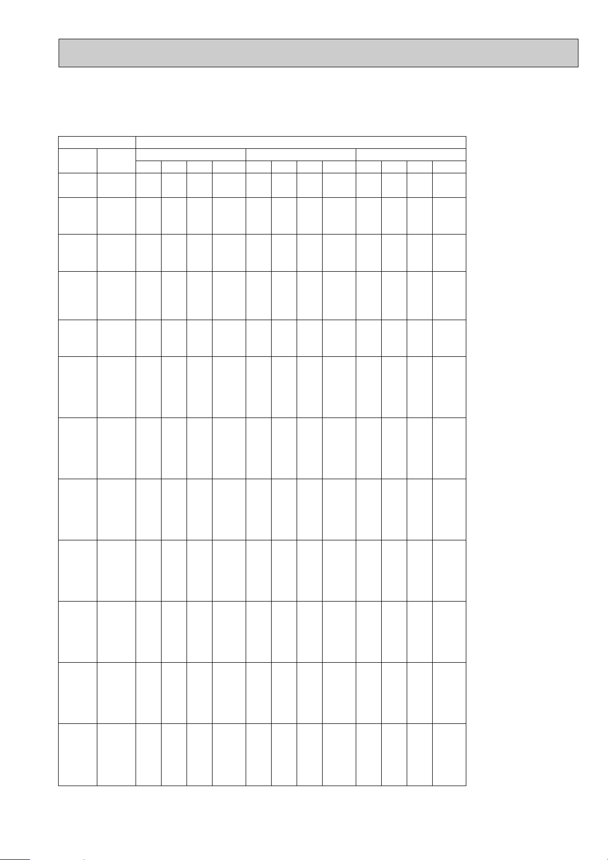
PERFORMANCE DATA
COOLING operation(240V)
SLH-2AR
CAPACITY : 5.1 kW INPUT : 2310 W SHF : 0.64
INDOOR INDOOR
D.B.(;) W.B.(;)
21
21
22
22
22
23
23
23
24
24
24
24
25
25
25
26
26
26
26
26
27
27
27
27
27
28
28
28
28
28
29
29
29
29
29
30
30
30
30
30
31
31
31
31
31
32
32
32
32
32
18
20
18
20
22
18
20
22
18
20
22
24
20
22
24
18
20
22
24
26
18
20
22
24
26
18
20
22
24
26
18
20
22
24
26
18
20
22
24
26
18
20
22
24
26
18
20
22
24
26
Q SHC SHF INPUT Q SHC SHF INPUT Q SHC SHF INPUT
5.00
5.25
5.00
5.25
5.56
5.00
5.25
5.56
5.00
5.25
5.56
5.87
5.25
5.56
5.87
5.00
5.25
5.56
5.87
6.17
5.00
5.25
5.56
5.87
6.17
5.00
5.25
5.56
5.87
6.17
5.00
5.25
5.56
5.87
6.17
5.00
5.25
5.56
5.87
6.17
5.00
5.25
5.56
5.87
6.17
5.00
5.25
5.56
5.87
6.17
35 40 46
2.30
1.79
2.50
2.00
1.45
2.70
2.21
1.67
2.90
2.42
1.89
1.29
2.63
2.11
1.52
3.30
2.84
2.33
1.76
1.11
3.50
3.05
2.56
1.99
1.36
3.70
3.26
2.78
2.23
1.60
3.90
3.47
3.00
2.46
1.85
4.10
3.68
3.22
2.70
2.10
4.30
3.89
3.45
2.93
2.34
4.50
4.10
3.67
3.17
2.59
0.46
0.34
0.50
0.38
0.26
0.54
0.42
0.30
0.58
0.46
0.34
0.22
0.50
0.38
0.26
0.66
0.54
0.42
0.30
0.18
0.70
0.58
0.46
0.34
0.22
0.74
0.62
0.50
0.38
0.26
0.78
0.66
0.54
0.42
0.30
0.82
0.70
0.58
0.46
0.34
0.86
0.74
0.62
0.50
0.38
0.90
0.78
0.66
0.54
0.42
2264
2356
2264
2356
2449
2264
2356
2449
2264
2356
2449
2541
2356
2449
2541
2264
2356
2449
2541
2633
2264
2356
2449
2541
2633
2264
2356
2449
2541
2633
2264
2356
2449
2541
2633
2264
2356
2449
2541
2633
2264
2356
2449
2541
2633
2264
2356
2449
2541
2633
4.59
4.90
4.59
4.90
5.20
4.59
4.90
5.20
4.59
4.90
5.20
5.51
4.90
5.20
5.51
4.59
4.90
5.20
5.51
5.81
4.59
4.90
5.20
5.51
5.81
4.59
4.90
5.20
5.51
5.81
4.59
4.90
5.20
5.51
5.81
4.59
4.90
5.20
5.51
5.81
4.59
4.90
5.20
5.51
5.81
4.59
4.90
5.20
5.51
5.81
OUTDOOR D.B.(;)
2.11
1.66
2.30
1.86
1.35
2.48
2.06
1.56
2.66
2.25
1.77
1.21
2.45
1.98
1.43
3.03
2.64
2.18
1.65
1.05
3.21
2.84
2.39
1.87
1.28
3.40
3.04
2.60
2.09
1.51
3.58
3.23
2.81
2.31
1.74
3.76
3.43
3.02
2.53
1.98
3.95
3.62
3.23
2.75
2.21
4.13
3.82
3.43
2.97
2.44
0.46
0.34
0.50
0.38
0.26
0.54
0.42
0.30
0.58
0.46
0.34
0.22
0.50
0.38
0.26
0.66
0.54
0.42
0.30
0.18
0.70
0.58
0.46
0.34
0.22
0.74
0.62
0.50
0.38
0.26
0.78
0.66
0.54
0.42
0.30
0.82
0.70
0.58
0.46
0.34
0.86
0.74
0.62
0.50
0.38
0.90
0.78
0.66
0.54
0.42
2402
2472
2402
2472
2587
2402
2472
2587
2402
2472
2587
2657
2472
2587
2657
2402
2472
2587
2657
2749
2402
2472
2587
2657
2749
2402
2472
2587
2657
2749
2402
2472
2587
2657
2749
2402
2472
2587
2657
2749
2402
2472
2587
2657
2749
2402
2472
2587
2657
2749
4.23
4.54
4.23
4.54
4.85
4.23
4.54
4.85
4.23
4.54
4.85
5.20
4.54
4.85
5.20
4.23
4.54
4.85
5.20
5.46
4.23
4.54
4.85
5.20
5.46
4.23
4.54
4.85
5.20
5.46
4.23
4.54
4.85
5.20
5.46
4.23
4.54
4.85
5.20
5.46
4.23
4.54
4.85
5.20
5.46
4.23
4.54
4.85
5.20
5.46
1.95
1.54
2.12
1.72
1.26
2.29
1.91
1.45
2.46
2.09
1.65
1.14
2.27
1.84
1.35
2.79
2.45
2.03
1.56
0.98
2.96
2.63
2.23
1.77
1.20
3.13
2.81
2.42
1.98
1.42
3.30
3.00
2.62
2.18
1.64
3.47
3.18
2.81
2.39
1.86
3.64
3.36
3.00
2.60
2.07
3.81
3.54
3.20
2.81
2.29
0.46
0.34
0.50
0.38
0.26
0.54
0.42
0.30
0.58
0.46
0.34
0.22
0.50
0.38
0.26
0.66
0.54
0.42
0.30
0.18
0.70
0.58
0.46
0.34
0.22
0.74
0.62
0.50
0.38
0.26
0.78
0.66
0.54
0.42
0.30
0.82
0.70
0.58
0.46
0.34
0.86
0.74
0.62
0.50
0.38
0.90
0.78
0.66
0.54
0.42
2495
2610
2495
2610
2680
2495
2610
2680
2495
2610
2680
2772
2610
2680
2772
2495
2610
2680
2772
2864
2495
2610
2680
2772
2864
2495
2610
2680
2772
2864
2495
2610
2680
2772
2864
2495
2610
2680
2772
2864
2495
2610
2680
2772
2864
2495
2610
2680
2772
2864
19
Page 20

OUTDOOR D.B.(;)
INDOOR INDOOR
21 25 27 30
D.B.(;) W.B.(;)
Q SHC SHF INPUT Q SHC SHF INPUT Q SHC SHF INPUT Q SHC SHF INPUT
21
21
22
22
22
23
23
23
24
24
24
24
25
25
25
26
26
26
26
26
27
27
27
27
27
28
28
28
28
28
29
29
29
29
29
30
30
30
30
30
31
31
31
31
31
32
32
32
32
32
18
20
18
20
22
18
20
22
18
20
22
24
20
22
24
18
20
22
24
26
18
20
22
24
26
18
20
22
24
26
18
20
22
24
26
18
20
22
24
26
18
20
22
24
26
18
20
22
24
26
3.06
3.19
3.06
3.19
3.32
3.06
3.19
3.32
3.06
3.19
3.32
3.48
3.19
3.32
3.48
3.06
3.19
3.32
3.48
3.59
3.06
3.19
3.32
3.48
3.59
3.06
3.19
3.32
3.48
3.59
3.06
3.19
3.32
3.48
3.59
3.06
3.19
3.32
3.48
3.59
3.06
3.19
3.32
3.48
3.59
3.06
3.19
3.32
3.48
3.59
0.55
0.43
0.59
0.47
0.35
0.63
0.51
0.39
0.67
0.55
0.43
0.31
0.59
0.47
0.35
0.75
0.63
0.51
0.39
0.27
0.79
0.67
0.55
0.43
0.31
0.83
0.71
0.59
0.47
0.35
0.87
0.75
0.63
0.51
0.39
0.91
0.79
0.67
0.55
0.43
0.95
0.83
0.71
0.59
0.47
0.99
0.87
0.75
0.63
0.51
792
832
792
832
861
792
832
861
792
832
861
901
832
861
901
792
832
861
901
950
792
832
861
901
950
792
832
861
901
950
792
832
861
901
950
792
832
861
901
950
792
832
861
901
950
792
832
861
901
950
1.68
1.37
1.80
1.50
1.16
1.92
1.62
1.29
2.05
1.75
1.43
1.08
1.88
1.56
1.22
2.29
2.01
1.69
1.36
0.97
2.41
2.13
1.82
1.50
1.11
2.54
2.26
1.96
1.64
1.26
2.66
2.39
2.09
1.78
1.40
2.78
2.52
2.22
1.92
1.54
2.90
2.64
2.35
2.06
1.69
3.02
2.77
2.49
2.19
1.83
2.93
3.06
2.93
3.06
3.20
2.93
3.06
3.20
2.93
3.06
3.20
3.35
3.06
3.20
3.35
2.93
3.06
3.20
3.35
3.48
2.93
3.06
3.20
3.35
3.48
2.93
3.06
3.20
3.35
3.48
2.93
3.06
3.20
3.35
3.48
2.93
3.06
3.20
3.35
3.48
2.93
3.06
3.20
3.35
3.48
2.93
3.06
3.20
3.35
3.48
0.55
0.43
0.59
0.47
0.35
0.63
0.51
0.39
0.67
0.55
0.43
0.31
0.59
0.47
0.35
0.75
0.63
0.51
0.39
0.27
0.79
0.67
0.55
0.43
0.31
0.83
0.71
0.59
0.47
0.35
0.87
0.75
0.63
0.51
0.39
0.91
0.79
0.67
0.55
0.43
0.95
0.83
0.71
0.59
0.47
0.99
0.87
0.75
0.63
0.51
832
881
832
881
916
832
881
916
832
881
916
950
881
916
950
832
881
916
950
1000
832
881
916
950
1000
832
881
916
950
1000
832
881
916
950
1000
832
881
916
950
1000
832
881
916
950
1000
832
881
916
950
1000
1.61
1.31
1.73
1.44
1.12
1.84
1.56
1.25
1.96
1.68
1.38
1.04
1.80
1.50
1.17
2.19
1.92
1.63
1.31
0.94
2.31
2.05
1.76
1.44
1.08
2.43
2.17
1.89
1.58
1.22
2.54
2.29
2.01
1.71
1.36
2.66
2.41
2.14
1.84
1.50
2.78
2.54
2.27
1.98
1.64
2.90
2.66
2.40
2.11
1.78
2.81
2.96
2.81
2.96
3.12
2.81
2.96
3.12
2.81
2.96
3.12
3.28
2.96
3.12
3.28
2.81
2.96
3.12
3.28
3.43
2.81
2.96
3.12
3.28
3.43
2.81
2.96
3.12
3.28
3.43
2.81
2.96
3.12
3.28
3.43
2.81
2.96
3.12
3.28
3.43
2.81
2.96
3.12
3.28
3.43
2.81
2.96
3.12
3.28
3.43
0.55
0.43
0.59
0.47
0.35
0.63
0.51
0.39
0.67
0.55
0.43
0.31
0.59
0.47
0.35
0.75
0.63
0.51
0.39
0.27
0.79
0.67
0.55
0.43
0.31
0.83
0.71
0.59
0.47
0.35
0.87
0.75
0.63
0.51
0.39
0.91
0.79
0.67
0.55
0.43
0.95
0.83
0.71
0.59
0.47
0.99
0.87
0.75
0.63
0.51
871
901
871
901
941
871
901
941
871
901
941
980
901
941
980
871
901
941
980
1030
871
901
941
980
1030
871
901
941
980
1030
871
901
941
980
1030
871
901
941
980
1030
871
901
941
980
1030
871
901
941
980
1030
1.54
1.27
1.66
1.39
1.09
1.77
1.51
1.22
1.88
1.63
1.34
1.02
1.75
1.47
1.15
2.11
1.87
1.59
1.28
0.93
2.22
1.99
1.72
1.41
1.06
2.33
2.10
1.84
1.54
1.20
2.44
2.22
1.97
1.67
1.34
2.56
2.34
2.09
1.80
1.48
2.67
2.46
2.22
1.93
1.61
2.78
2.58
2.34
2.06
1.75
2.70
2.86
2.70
2.86
2.99
2.70
2.86
2.99
2.70
2.86
2.99
3.17
2.86
2.99
3.17
2.70
2.86
2.99
3.17
3.33
2.70
2.86
2.99
3.17
3.33
2.70
2.86
2.99
3.17
3.33
2.70
2.86
2.99
3.17
3.33
2.70
2.86
2.99
3.17
3.33
2.70
2.86
2.99
3.17
3.33
2.70
2.86
2.99
3.17
3.33
0.55
0.43
0.59
0.47
0.35
0.63
0.51
0.39
0.67
0.55
0.43
0.31
0.59
0.47
0.35
0.75
0.63
0.51
0.39
0.27
0.79
0.67
0.55
0.43
0.31
0.83
0.71
0.59
0.47
0.35
0.87
0.75
0.63
0.51
0.39
0.91
0.79
0.67
0.55
0.43
0.95
0.83
0.71
0.59
0.47
0.99
0.87
0.75
0.63
0.51
911
941
911
941
980
911
941
980
911
941
980
1030
941
980
1030
911
941
980
1030
1059
911
941
980
1030
1059
911
941
980
1030
1059
911
941
980
1030
1059
911
941
980
1030
1059
911
941
980
1030
1059
911
941
980
1030
1059
1.49
1.23
1.60
1.34
1.05
1.70
1.46
1.17
1.81
1.57
1.29
0.98
1.69
1.41
1.11
2.03
1.80
1.52
1.24
0.90
2.14
1.92
1.64
1.36
1.03
2.24
2.03
1.76
1.49
1.16
2.35
2.15
1.88
1.62
1.30
2.46
2.26
2.00
1.74
1.43
2.57
2.37
2.12
1.87
1.56
2.68
2.49
2.24
2.00
1.70
PERFORMANCE DATA
COOLING operation(220V)
SL-1AR
CAPACITY : 2.6 kW INPUT : 990 W SHF : 0.73
20
Page 21
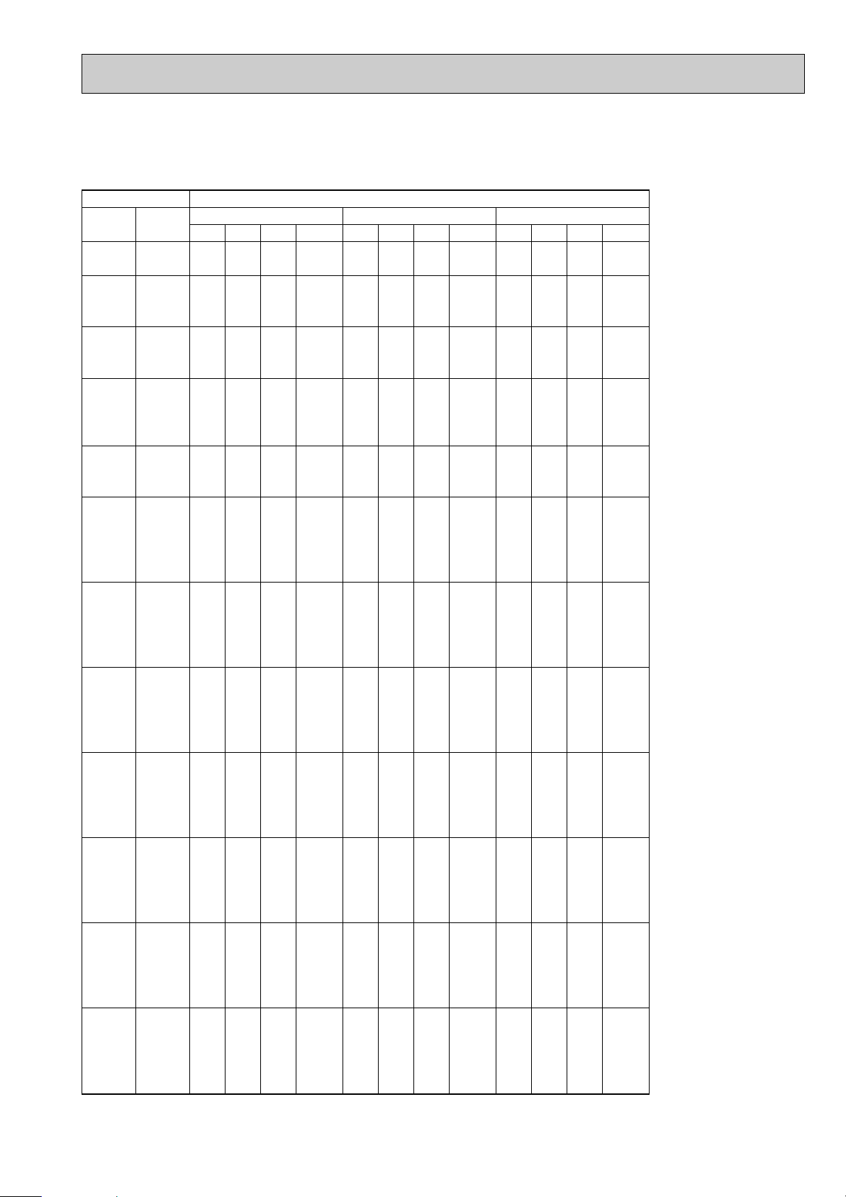
PERFORMANCE DATA
COOLING operation(220V)
SL-1AR
CAPACITY : 2.6 kW INPUT : 990 W SHF : 0.73
INDOOR INDOOR
D.B.(;) W.B.(;)
21
21
22
22
22
23
23
23
24
24
24
24
25
25
25
26
26
26
26
26
27
27
27
27
27
28
28
28
28
28
29
29
29
29
29
30
30
30
30
30
31
31
31
31
31
32
32
32
32
32
18
20
18
20
22
18
20
22
18
20
22
24
20
22
24
18
20
22
24
26
18
20
22
24
26
18
20
22
24
26
18
20
22
24
26
18
20
22
24
26
18
20
22
24
26
18
20
22
24
26
Q SHC SHF INPUT Q SHC SHF INPUT Q SHC SHF INPUT
2.55
2.68
2.55
2.68
2.83
2.55
2.68
2.83
2.55
2.68
2.83
2.99
2.68
2.83
2.99
2.55
2.68
2.83
2.99
3.15
2.55
2.68
2.83
2.99
3.15
2.55
2.68
2.83
2.99
3.15
2.55
2.68
2.83
2.99
3.15
2.55
2.68
2.83
2.99
3.15
2.55
2.68
2.83
2.99
3.15
2.55
2.68
2.83
2.99
3.15
35 40 46
1.40
1.15
1.50
1.26
0.99
1.61
1.37
1.11
1.71
1.47
1.22
0.93
1.58
1.33
1.05
1.91
1.69
1.45
1.17
0.85
2.01
1.79
1.56
1.29
0.98
2.11
1.90
1.67
1.41
1.10
2.22
2.01
1.79
1.52
1.23
2.32
2.12
1.90
1.64
1.35
2.42
2.22
2.01
1.76
1.48
2.52
2.33
2.13
1.88
1.60
0.55
0.43
0.59
0.47
0.35
0.63
0.51
0.39
0.67
0.55
0.43
0.31
0.59
0.47
0.35
0.75
0.63
0.51
0.39
0.27
0.79
0.67
0.55
0.43
0.31
0.83
0.71
0.59
0.47
0.35
0.87
0.75
0.63
0.51
0.39
0.91
0.79
0.67
0.55
0.43
0.95
0.83
0.71
0.59
0.47
0.99
0.87
0.75
0.63
0.51
1010
1010
1049
1010
1049
1010
1049
1089
1010
1049
1089
1010
1049
1089
1129
1010
1049
1089
1129
1010
1049
1089
1129
1010
1049
1089
1129
1010
1049
1089
1129
1010
1049
1089
1129
1010
1049
1089
1129
970
970
970
970
970
970
970
970
970
970
970
2.34
2.50
2.34
2.50
2.65
2.34
2.50
2.65
2.34
2.50
2.65
2.81
2.50
2.65
2.81
2.34
2.50
2.65
2.81
2.96
2.34
2.50
2.65
2.81
2.96
2.34
2.50
2.65
2.81
2.96
2.34
2.50
2.65
2.81
2.96
2.34
2.50
2.65
2.81
2.96
2.34
2.50
2.65
2.81
2.96
2.34
2.50
2.65
2.81
2.96
OUTDOOR D.B.(;)
1.29
1.07
1.38
1.17
0.93
1.47
1.27
1.03
1.57
1.37
1.14
0.87
1.47
1.25
0.98
1.76
1.57
1.35
1.10
0.80
1.85
1.67
1.46
1.21
0.92
1.94
1.77
1.56
1.32
1.04
2.04
1.87
1.67
1.43
1.16
2.13
1.97
1.78
1.54
1.27
2.22
2.07
1.88
1.66
1.39
2.32
2.17
1.99
1.77
1.51
0.55
0.43
0.59
0.47
0.35
0.63
0.51
0.39
0.67
0.55
0.43
0.31
0.59
0.47
0.35
0.75
0.63
0.51
0.39
0.27
0.79
0.67
0.55
0.43
0.31
0.83
0.71
0.59
0.47
0.35
0.87
0.75
0.63
0.51
0.39
0.91
0.79
0.67
0.55
0.43
0.95
0.83
0.71
0.59
0.47
0.99
0.87
0.75
0.63
0.51
1030
1059
1030
1059
1109
1030
1059
1109
1030
1059
1109
1139
1059
1109
1139
1030
1059
1109
1139
1178
1030
1059
1109
1139
1178
1030
1059
1109
1139
1178
1030
1059
1109
1139
1178
1030
1059
1109
1139
1178
1030
1059
1109
1139
1178
1030
1059
1109
1139
1178
2.16
2.31
2.16
2.31
2.47
2.16
2.31
2.47
2.16
2.31
2.47
2.65
2.31
2.47
2.65
2.16
2.31
2.47
2.65
2.78
2.16
2.31
2.47
2.65
2.78
2.16
2.31
2.47
2.65
2.78
2.16
2.31
2.47
2.65
2.78
2.16
2.31
2.47
2.65
2.78
2.16
2.31
2.47
2.65
2.78
2.16
2.31
2.47
2.65
2.78
1.19
1.00
1.27
1.09
0.86
1.36
1.18
0.96
1.45
1.27
1.06
0.82
1.37
1.16
0.93
1.62
1.46
1.26
1.03
0.75
1.70
1.55
1.36
1.14
0.86
1.79
1.64
1.46
1.25
0.97
1.88
1.74
1.56
1.35
1.08
1.96
1.83
1.65
1.46
1.20
2.05
1.92
1.75
1.56
1.31
2.14
2.01
1.85
1.67
1.42
0.55
0.43
0.59
0.47
0.35
0.63
0.51
0.39
0.67
0.55
0.43
0.31
0.59
0.47
0.35
0.75
0.63
0.51
0.39
0.27
0.79
0.67
0.55
0.43
0.31
0.83
0.71
0.59
0.47
0.35
0.87
0.75
0.63
0.51
0.39
0.91
0.79
0.67
0.55
0.43
0.95
0.83
0.71
0.59
0.47
0.99
0.87
0.75
0.63
0.51
1069
1119
1069
1119
1148
1069
1119
1148
1069
1119
1148
1188
1119
1148
1188
1069
1119
1148
1188
1228
1069
1119
1148
1188
1228
1069
1119
1148
1188
1228
1069
1119
1148
1188
1228
1069
1119
1148
1188
1228
1069
1119
1148
1188
1228
1069
1119
1148
1188
1228
21
Page 22

OUTDOOR D.B.(;)
INDOOR INDOOR
21 25 27 30
D.B.(;) W.B.(;)
Q SHC SHF INPUT Q SHC SHF INPUT Q SHC SHF INPUT Q SHC SHF INPUT
21
21
22
22
22
23
23
23
24
24
24
24
25
25
25
26
26
26
26
26
27
27
27
27
27
28
28
28
28
28
29
29
29
29
29
30
30
30
30
30
31
31
31
31
31
32
32
32
32
32
18
20
18
20
22
18
20
22
18
20
22
24
20
22
24
18
20
22
24
26
18
20
22
24
26
18
20
22
24
26
18
20
22
24
26
18
20
22
24
26
18
20
22
24
26
18
20
22
24
26
3.06
3.19
3.06
3.19
3.32
3.06
3.19
3.32
3.06
3.19
3.32
3.48
3.19
3.32
3.48
3.06
3.19
3.32
3.48
3.59
3.06
3.19
3.32
3.48
3.59
3.06
3.19
3.32
3.48
3.59
3.06
3.19
3.32
3.48
3.59
3.06
3.19
3.32
3.48
3.59
3.06
3.19
3.32
3.48
3.59
3.06
3.19
3.32
3.48
3.59
0.55
0.43
0.59
0.47
0.35
0.63
0.51
0.39
0.67
0.55
0.43
0.31
0.59
0.47
0.35
0.75
0.63
0.51
0.39
0.27
0.79
0.67
0.55
0.43
0.31
0.83
0.71
0.59
0.47
0.35
0.87
0.75
0.63
0.51
0.39
0.91
0.79
0.67
0.55
0.43
0.95
0.83
0.71
0.59
0.47
0.99
0.87
0.75
0.63
0.51
824
865
824
865
896
824
865
896
824
865
896
937
865
896
937
824
865
896
937
989
824
865
896
937
989
824
865
896
937
989
824
865
896
937
989
824
865
896
937
989
824
865
896
937
989
824
865
896
937
989
1.68
1.37
1.80
1.50
1.16
1.92
1.62
1.29
2.05
1.75
1.43
1.08
1.88
1.56
1.22
2.29
2.01
1.69
1.36
0.97
2.41
2.13
1.82
1.50
1.11
2.54
2.26
1.96
1.64
1.26
2.66
2.39
2.09
1.78
1.40
2.78
2.52
2.22
1.92
1.54
2.90
2.64
2.35
2.06
1.69
3.02
2.77
2.49
2.19
1.83
2.93
3.06
2.93
3.06
3.20
2.93
3.06
3.20
2.93
3.06
3.20
3.35
3.06
3.20
3.35
2.93
3.06
3.20
3.35
3.48
2.93
3.06
3.20
3.35
3.48
2.93
3.06
3.20
3.35
3.48
2.93
3.06
3.20
3.35
3.48
2.93
3.06
3.20
3.35
3.48
2.93
3.06
3.20
3.35
3.48
2.93
3.06
3.20
3.35
3.48
0.55
0.43
0.59
0.47
0.35
0.63
0.51
0.39
0.67
0.55
0.43
0.31
0.59
0.47
0.35
0.75
0.63
0.51
0.39
0.27
0.79
0.67
0.55
0.43
0.31
0.83
0.71
0.59
0.47
0.35
0.87
0.75
0.63
0.51
0.39
0.91
0.79
0.67
0.55
0.43
0.95
0.83
0.71
0.59
0.47
0.99
0.87
0.75
0.63
0.51
865
917
865
917
953
865
917
953
865
917
953
989
917
953
989
865
917
953
989
1040
865
917
953
989
1040
865
917
953
989
1040
865
917
953
989
1040
865
917
953
989
1040
865
917
953
989
1040
865
917
953
989
1040
1.61
1.31
1.73
1.44
1.12
1.84
1.56
1.25
1.96
1.68
1.38
1.04
1.80
1.50
1.17
2.19
1.92
1.63
1.31
0.94
2.31
2.05
1.76
1.44
1.08
2.43
2.17
1.89
1.58
1.22
2.54
2.29
2.01
1.71
1.36
2.66
2.41
2.14
1.84
1.50
2.78
2.54
2.27
1.98
1.64
2.90
2.66
2.40
2.11
1.78
2.81
2.96
2.81
2.96
3.12
2.81
2.96
3.12
2.81
2.96
3.12
3.28
2.96
3.12
3.28
2.81
2.96
3.12
3.28
3.43
2.81
2.96
3.12
3.28
3.43
2.81
2.96
3.12
3.28
3.43
2.81
2.96
3.12
3.28
3.43
2.81
2.96
3.12
3.28
3.43
2.81
2.96
3.12
3.28
3.43
2.81
2.96
3.12
3.28
3.43
0.55
0.43
0.59
0.47
0.35
0.63
0.51
0.39
0.67
0.55
0.43
0.31
0.59
0.47
0.35
0.75
0.63
0.51
0.39
0.27
0.79
0.67
0.55
0.43
0.31
0.83
0.71
0.59
0.47
0.35
0.87
0.75
0.63
0.51
0.39
0.91
0.79
0.67
0.55
0.43
0.95
0.83
0.71
0.59
0.47
0.99
0.87
0.75
0.63
0.51
906
937
906
937
979
906
937
979
906
937
979
1020
937
979
1020
906
937
979
1020
1071
906
937
979
1020
1071
906
937
979
1020
1071
906
937
979
1020
1071
906
937
979
1020
1071
906
937
979
1020
1071
906
937
979
1020
1071
1.54
1.27
1.66
1.39
1.09
1.77
1.51
1.22
1.88
1.63
1.34
1.02
1.75
1.47
1.15
2.11
1.87
1.59
1.28
0.93
2.22
1.99
1.72
1.41
1.06
2.33
2.10
1.84
1.54
1.20
2.44
2.22
1.97
1.67
1.34
2.56
2.34
2.09
1.80
1.48
2.67
2.46
2.22
1.93
1.61
2.78
2.58
2.34
2.06
1.75
2.70
2.86
2.70
2.86
2.99
2.70
2.86
2.99
2.70
2.86
2.99
3.17
2.86
2.99
3.17
2.70
2.86
2.99
3.17
3.33
2.70
2.86
2.99
3.17
3.33
2.70
2.86
2.99
3.17
3.33
2.70
2.86
2.99
3.17
3.33
2.70
2.86
2.99
3.17
3.33
2.70
2.86
2.99
3.17
3.33
2.70
2.86
2.99
3.17
3.33
0.55
0.43
0.59
0.47
0.35
0.63
0.51
0.39
0.67
0.55
0.43
0.31
0.59
0.47
0.35
0.75
0.63
0.51
0.39
0.27
0.79
0.67
0.55
0.43
0.31
0.83
0.71
0.59
0.47
0.35
0.87
0.75
0.63
0.51
0.39
0.91
0.79
0.67
0.55
0.43
0.95
0.83
0.71
0.59
0.47
0.99
0.87
0.75
0.63
0.51
948
979
948
979
1020
948
979
1020
948
979
1020
1071
979
1020
1071
948
979
1020
1071
1102
948
979
1020
1071
1102
948
979
1020
1071
1102
948
979
1020
1071
1102
948
979
1020
1071
1102
948
979
1020
1071
1102
948
979
1020
1071
1102
1.49
1.23
1.60
1.34
1.05
1.70
1.46
1.17
1.81
1.57
1.29
0.98
1.69
1.41
1.11
2.03
1.80
1.52
1.24
0.90
2.14
1.92
1.64
1.36
1.03
2.24
2.03
1.76
1.49
1.16
2.35
2.15
1.88
1.62
1.30
2.46
2.26
2.00
1.74
1.43
2.57
2.37
2.12
1.87
1.56
2.68
2.49
2.24
2.00
1.70
PERFORMANCE DATA
COOLING operation(240V)
SL-1AR
CAPACITY : 2.6 kW INPUT : 1030 W SHF : 0.73
22
Page 23
PERFORMANCE DATA
COOLING operation(240V)
SL-1AR
CAPACITY : 2.6 kW INPUT : 1030 W SHF : 0.73
INDOOR INDOOR
D.B.(;) W.B.(;)
21
21
22
22
22
23
23
23
24
24
24
24
25
25
25
26
26
26
26
26
27
27
27
27
27
28
28
28
28
28
29
29
29
29
29
30
30
30
30
30
31
31
31
31
31
32
32
32
32
32
18
20
18
20
22
18
20
22
18
20
22
24
20
22
24
18
20
22
24
26
18
20
22
24
26
18
20
22
24
26
18
20
22
24
26
18
20
22
24
26
18
20
22
24
26
18
20
22
24
26
Q SHC SHF INPUT Q SHC SHF INPUT Q SHC SHF INPUT
2.55
2.68
2.55
2.68
2.83
2.55
2.68
2.83
2.55
2.68
2.83
2.99
2.68
2.83
2.99
2.55
2.68
2.83
2.99
3.15
2.55
2.68
2.83
2.99
3.15
2.55
2.68
2.83
2.99
3.15
2.55
2.68
2.83
2.99
3.15
2.55
2.68
2.83
2.99
3.15
2.55
2.68
2.83
2.99
3.15
2.55
2.68
2.83
2.99
3.15
35 40 46
1.40
1.15
1.50
1.26
0.99
1.61
1.37
1.11
1.71
1.47
1.22
0.93
1.58
1.33
1.05
1.91
1.69
1.45
1.17
0.85
2.01
1.79
1.56
1.29
0.98
2.11
1.90
1.67
1.41
1.10
2.22
2.01
1.79
1.52
1.23
2.32
2.12
1.90
1.64
1.35
2.42
2.22
2.01
1.76
1.48
2.52
2.33
2.13
1.88
1.60
0.55
0.43
0.59
0.47
0.35
0.63
0.51
0.39
0.67
0.55
0.43
0.31
0.59
0.47
0.35
0.75
0.63
0.51
0.39
0.27
0.79
0.67
0.55
0.43
0.31
0.83
0.71
0.59
0.47
0.35
0.87
0.75
0.63
0.51
0.39
0.91
0.79
0.67
0.55
0.43
0.95
0.83
0.71
0.59
0.47
0.99
0.87
0.75
0.63
0.51
1009
1051
1009
1051
1092
1009
1051
1092
1009
1051
1092
1133
1051
1092
1133
1009
1051
1092
1133
1174
1009
1051
1092
1133
1174
1009
1051
1092
1133
1174
1009
1051
1092
1133
1174
1009
1051
1092
1133
1174
1009
1051
1092
1133
1174
1009
1051
1092
1133
1174
2.34
2.50
2.34
2.50
2.65
2.34
2.50
2.65
2.34
2.50
2.65
2.81
2.50
2.65
2.81
2.34
2.50
2.65
2.81
2.96
2.34
2.50
2.65
2.81
2.96
2.34
2.50
2.65
2.81
2.96
2.34
2.50
2.65
2.81
2.96
2.34
2.50
2.65
2.81
2.96
2.34
2.50
2.65
2.81
2.96
2.34
2.50
2.65
2.81
2.96
OUTDOOR D.B.(;)
1.29
1.07
1.38
1.17
0.93
1.47
1.27
1.03
1.57
1.37
1.14
0.87
1.47
1.25
0.98
1.76
1.57
1.35
1.10
0.80
1.85
1.67
1.46
1.21
0.92
1.94
1.77
1.56
1.32
1.04
2.04
1.87
1.67
1.43
1.16
2.13
1.97
1.78
1.54
1.27
2.22
2.07
1.88
1.66
1.39
2.32
2.17
1.99
1.77
1.51
0.55
0.43
0.59
0.47
0.35
0.63
0.51
0.39
0.67
0.55
0.43
0.31
0.59
0.47
0.35
0.75
0.63
0.51
0.39
0.27
0.79
0.67
0.55
0.43
0.31
0.83
0.71
0.59
0.47
0.35
0.87
0.75
0.63
0.51
0.39
0.91
0.79
0.67
0.55
0.43
0.95
0.83
0.71
0.59
0.47
0.99
0.87
0.75
0.63
0.51
1071
1102
1071
1102
1154
1071
1102
1154
1071
1102
1154
1185
1102
1154
1185
1071
1102
1154
1185
1226
1071
1102
1154
1185
1226
1071
1102
1154
1185
1226
1071
1102
1154
1185
1226
1071
1102
1154
1185
1226
1071
1102
1154
1185
1226
1071
1102
1154
1185
1226
2.16
2.31
2.16
2.31
2.47
2.16
2.31
2.47
2.16
2.31
2.47
2.65
2.31
2.47
2.65
2.16
2.31
2.47
2.65
2.78
2.16
2.31
2.47
2.65
2.78
2.16
2.31
2.47
2.65
2.78
2.16
2.31
2.47
2.65
2.78
2.16
2.31
2.47
2.65
2.78
2.16
2.31
2.47
2.65
2.78
2.16
2.31
2.47
2.65
2.78
1.19
1.00
1.27
1.09
0.86
1.36
1.18
0.96
1.45
1.27
1.06
0.82
1.37
1.16
0.93
1.62
1.46
1.26
1.03
0.75
1.70
1.55
1.36
1.14
0.86
1.79
1.64
1.46
1.25
0.97
1.88
1.74
1.56
1.35
1.08
1.96
1.83
1.65
1.46
1.20
2.05
1.92
1.75
1.56
1.31
2.14
2.01
1.85
1.67
1.42
0.55
0.43
0.59
0.47
0.35
0.63
0.51
0.39
0.67
0.55
0.43
0.31
0.59
0.47
0.35
0.75
0.63
0.51
0.39
0.27
0.79
0.67
0.55
0.43
0.31
0.83
0.71
0.59
0.47
0.35
0.87
0.75
0.63
0.51
0.39
0.91
0.79
0.67
0.55
0.43
0.95
0.83
0.71
0.59
0.47
0.99
0.87
0.75
0.63
0.51
1112
1164
1112
1164
1195
1112
1164
1195
1112
1164
1195
1236
1164
1195
1236
1112
1164
1195
1236
1277
1112
1164
1195
1236
1277
1112
1164
1195
1236
1277
1112
1164
1195
1236
1277
1112
1164
1195
1236
1277
1112
1164
1195
1236
1277
1112
1164
1195
1236
1277
23
Page 24

OUTDOOR D.B.(;)
INDOOR INDOOR
21 25 27 30
D.B.(;) W.B.(;)
Q SHC SHF INPUT Q SHC SHF INPUT Q SHC SHF INPUT Q SHC SHF INPUT
21
21
22
22
22
23
23
23
24
24
24
24
25
25
25
26
26
26
26
26
27
27
27
27
27
28
28
28
28
28
29
29
29
29
29
30
30
30
30
30
31
31
31
31
31
32
32
32
32
32
18
20
18
20
22
18
20
22
18
20
22
24
20
22
24
18
20
22
24
26
18
20
22
24
26
18
20
22
24
26
18
20
22
24
26
18
20
22
24
26
18
20
22
24
26
18
20
22
24
26
4.70
4.90
4.70
4.90
5.10
4.70
4.90
5.10
4.70
4.90
5.10
5.36
4.90
5.10
5.36
4.70
4.90
5.10
5.36
5.52
4.70
4.90
5.10
5.36
5.52
4.70
4.90
5.10
5.36
5.52
4.70
4.90
5.10
5.36
5.52
4.70
4.90
5.10
5.36
5.52
4.70
4.90
5.10
5.36
5.52
4.70
4.90
5.10
5.36
5.52
0.51
0.39
0.55
0.43
0.31
0.59
0.47
0.35
0.63
0.51
0.39
0.27
0.55
0.43
0.31
0.71
0.59
0.47
0.35
0.23
0.75
0.63
0.51
0.39
0.27
0.79
0.67
0.55
0.43
0.31
0.83
0.71
0.59
0.47
0.35
0.87
0.75
0.63
0.51
0.39
0.91
0.79
0.67
0.55
0.43
0.95
0.83
0.71
0.59
0.47
1312
1378
1312
1378
1427
1312
1378
1427
1312
1378
1427
1492
1378
1427
1492
1312
1378
1427
1492
1574
1312
1378
1427
1492
1574
1312
1378
1427
1492
1574
1312
1378
1427
1492
1574
1312
1378
1427
1492
1574
1312
1378
1427
1492
1574
1312
1378
1427
1492
1574
2.40
1.91
2.59
2.11
1.58
2.77
2.30
1.79
2.96
2.50
1.99
1.45
2.70
2.19
1.66
3.34
2.89
2.40
1.88
1.27
3.53
3.09
2.60
2.09
1.49
3.71
3.28
2.81
2.30
1.71
3.90
3.48
3.01
2.52
1.93
4.09
3.68
3.21
2.73
2.15
4.28
3.87
3.42
2.95
2.37
4.47
4.07
3.62
3.16
2.59
4.50
4.70
4.50
4.70
4.92
4.50
4.70
4.92
4.50
4.70
4.92
5.16
4.70
4.92
5.16
4.50
4.70
4.92
5.16
5.36
4.50
4.70
4.92
5.16
5.36
4.50
4.70
4.92
5.16
5.36
4.50
4.70
4.92
5.16
5.36
4.50
4.70
4.92
5.16
5.36
4.50
4.70
4.92
5.16
5.36
4.50
4.70
4.92
5.16
5.36
0.51
0.39
0.55
0.43
0.31
0.59
0.47
0.35
0.63
0.51
0.39
0.27
0.55
0.43
0.31
0.71
0.59
0.47
0.35
0.23
0.75
0.63
0.51
0.39
0.27
0.79
0.67
0.55
0.43
0.31
0.83
0.71
0.59
0.47
0.35
0.87
0.75
0.63
0.51
0.39
0.91
0.79
0.67
0.55
0.43
0.95
0.83
0.71
0.59
0.47
1378
1460
1378
1460
1517
1378
1460
1517
1378
1460
1517
1574
1460
1517
1574
1378
1460
1517
1574
1656
1378
1460
1517
1574
1656
1378
1460
1517
1574
1656
1378
1460
1517
1574
1656
1378
1460
1517
1574
1656
1378
1460
1517
1574
1656
1378
1460
1517
1574
1656
2.30
1.83
2.48
2.02
1.53
2.66
2.21
1.72
2.84
2.40
1.92
1.39
2.59
2.12
1.60
3.20
2.77
2.31
1.81
1.23
3.38
2.96
2.51
2.01
1.45
3.56
3.15
2.71
2.22
1.66
3.74
3.34
2.90
2.43
1.88
3.92
3.53
3.10
2.63
2.09
4.10
3.71
3.30
2.84
2.30
4.28
3.90
3.49
3.04
2.52
4.32
4.56
4.32
4.56
4.80
4.32
4.56
4.80
4.32
4.56
4.80
5.04
4.56
4.80
5.04
4.32
4.56
4.80
5.04
5.28
4.32
4.56
4.80
5.04
5.28
4.32
4.56
4.80
5.04
5.28
4.32
4.56
4.80
5.04
5.28
4.32
4.56
4.80
5.04
5.28
4.32
4.56
4.80
5.04
5.28
4.32
4.56
4.80
5.04
5.28
0.51
0.39
0.55
0.43
0.31
0.59
0.47
0.35
0.63
0.51
0.39
0.27
0.55
0.43
0.31
0.71
0.59
0.47
0.35
0.23
0.75
0.63
0.51
0.39
0.27
0.79
0.67
0.55
0.43
0.31
0.83
0.71
0.59
0.47
0.35
0.87
0.75
0.63
0.51
0.39
0.91
0.79
0.67
0.55
0.43
0.95
0.83
0.71
0.59
0.47
1443
1492
1443
1492
1558
1443
1492
1558
1443
1492
1558
1624
1492
1558
1624
1443
1492
1558
1624
1706
1443
1492
1558
1624
1706
1443
1492
1558
1624
1706
1443
1492
1558
1624
1706
1443
1492
1558
1624
1706
1443
1492
1558
1624
1706
1443
1492
1558
1624
1706
2.20
1.78
2.38
1.96
1.49
2.55
2.14
1.68
2.72
2.33
1.87
1.36
2.51
2.06
1.56
3.07
2.69
2.26
1.76
1.21
3.24
2.87
2.45
1.97
1.43
3.41
3.06
2.64
2.17
1.64
3.59
3.24
2.83
2.37
1.85
3.76
3.42
3.02
2.57
2.06
3.93
3.60
3.22
2.77
2.27
4.10
3.78
3.41
2.97
2.48
4.16
4.40
4.16
4.40
4.60
4.16
4.40
4.60
4.16
4.40
4.60
4.88
4.40
4.60
4.88
4.16
4.40
4.60
4.88
5.12
4.16
4.40
4.60
4.88
5.12
4.16
4.40
4.60
4.88
5.12
4.16
4.40
4.60
4.88
5.12
4.16
4.40
4.60
4.88
5.12
4.16
4.40
4.60
4.88
5.12
4.16
4.40
4.60
4.88
5.12
0.51
0.39
0.55
0.43
0.31
0.59
0.47
0.35
0.63
0.51
0.39
0.27
0.55
0.43
0.31
0.71
0.59
0.47
0.35
0.23
0.75
0.63
0.51
0.39
0.27
0.79
0.67
0.55
0.43
0.31
0.83
0.71
0.59
0.47
0.35
0.87
0.75
0.63
0.51
0.39
0.91
0.79
0.67
0.55
0.43
0.95
0.83
0.71
0.59
0.47
1509
1558
1509
1558
1624
1509
1558
1624
1509
1558
1624
1706
1558
1624
1706
1509
1558
1624
1706
1755
1509
1558
1624
1706
1755
1509
1558
1624
1706
1755
1509
1558
1624
1706
1755
1509
1558
1624
1706
1755
1509
1558
1624
1706
1755
1509
1558
1624
1706
1755
2.12
1.72
2.29
1.89
1.43
2.45
2.07
1.61
2.62
2.24
1.79
1.32
2.42
1.98
1.51
2.95
2.60
2.16
1.71
1.18
3.12
2.77
2.35
1.90
1.38
3.29
2.95
2.53
2.10
1.59
3.45
3.12
2.71
2.29
1.79
3.62
3.30
2.90
2.49
2.00
3.79
3.48
3.08
2.68
2.20
3.95
3.65
3.27
2.88
2.41
PERFORMANCE DATA
COOLING operation(220V)
SL-1.6AR
CAPACITY : 4.0 kW INPUT : 1640 W SHF : 0.69
24
Page 25

PERFORMANCE DATA
COOLING operation(220V)
SL-1.6AR
CAPACITY : 4.0 kW INPUT : 1640 W SHF : 0.69
INDOOR INDOOR
D.B.(;) W.B.(;)
21
21
22
22
22
23
23
23
24
24
24
24
25
25
25
26
26
26
26
26
27
27
27
27
27
28
28
28
28
28
29
29
29
29
29
30
30
30
30
30
31
31
31
31
31
32
32
32
32
32
18
20
18
20
22
18
20
22
18
20
22
24
20
22
24
18
20
22
24
26
18
20
22
24
26
18
20
22
24
26
18
20
22
24
26
18
20
22
24
26
18
20
22
24
26
18
20
22
24
26
Q SHC SHF INPUT Q SHC SHF INPUT Q SHC SHF INPUT
3.92
4.12
3.92
4.12
4.36
3.92
4.12
4.36
3.92
4.12
4.36
4.60
4.12
4.36
4.60
3.92
4.12
4.36
4.60
4.84
3.92
4.12
4.36
4.60
4.84
3.92
4.12
4.36
4.60
4.84
3.92
4.12
4.36
4.60
4.84
3.92
4.12
4.36
4.60
4.84
3.92
4.12
4.36
4.60
4.84
3.92
4.12
4.36
4.60
4.84
35 40 46
2.00
1.61
2.16
1.77
1.35
2.31
1.94
1.53
2.47
2.10
1.70
1.24
2.27
1.87
1.43
2.78
2.43
2.05
1.61
1.11
2.94
2.60
2.22
1.79
1.31
3.10
2.76
2.40
1.98
1.50
3.25
2.93
2.57
2.16
1.69
3.41
3.09
2.75
2.35
1.89
3.57
3.25
2.92
2.53
2.08
3.72
3.42
3.10
2.71
2.27
0.51
0.39
0.55
0.43
0.31
0.59
0.47
0.35
0.63
0.51
0.39
0.27
0.55
0.43
0.31
0.71
0.59
0.47
0.35
0.23
0.75
0.63
0.51
0.39
0.27
0.79
0.67
0.55
0.43
0.31
0.83
0.71
0.59
0.47
0.35
0.87
0.75
0.63
0.51
0.39
0.91
0.79
0.67
0.55
0.43
0.95
0.83
0.71
0.59
0.47
1607
1673
1607
1673
1738
1607
1673
1738
1607
1673
1738
1804
1673
1738
1804
1607
1673
1738
1804
1870
1607
1673
1738
1804
1870
1607
1673
1738
1804
1870
1607
1673
1738
1804
1870
1607
1673
1738
1804
1870
1607
1673
1738
1804
1870
1607
1673
1738
1804
1870
3.60
3.84
3.60
3.84
4.08
3.60
3.84
4.08
3.60
3.84
4.08
4.32
3.84
4.08
4.32
3.60
3.84
4.08
4.32
4.56
3.60
3.84
4.08
4.32
4.56
3.60
3.84
4.08
4.32
4.56
3.60
3.84
4.08
4.32
4.56
3.60
3.84
4.08
4.32
4.56
3.60
3.84
4.08
4.32
4.56
3.60
3.84
4.08
4.32
4.56
OUTDOOR D.B.(;)
1.84
1.50
1.98
1.65
1.26
2.12
1.80
1.43
2.27
1.96
1.59
1.17
2.11
1.75
1.34
2.56
2.27
1.92
1.51
1.05
2.70
2.42
2.08
1.68
1.23
2.84
2.57
2.24
1.86
1.41
2.99
2.73
2.41
2.03
1.60
3.13
2.88
2.57
2.20
1.78
3.28
3.03
2.73
2.38
1.96
3.42
3.19
2.90
2.55
2.14
0.51
0.39
0.55
0.43
0.31
0.59
0.47
0.35
0.63
0.51
0.39
0.27
0.55
0.43
0.31
0.71
0.59
0.47
0.35
0.23
0.75
0.63
0.51
0.39
0.27
0.79
0.67
0.55
0.43
0.31
0.83
0.71
0.59
0.47
0.35
0.87
0.75
0.63
0.51
0.39
0.91
0.79
0.67
0.55
0.43
0.95
0.83
0.71
0.59
0.47
1706
1755
1706
1755
1837
1706
1755
1837
1706
1755
1837
1886
1755
1837
1886
1706
1755
1837
1886
1952
1706
1755
1837
1886
1952
1706
1755
1837
1886
1952
1706
1755
1837
1886
1952
1706
1755
1837
1886
1952
1706
1755
1837
1886
1952
1706
1755
1837
1886
1952
3.32
3.56
3.32
3.56
3.80
3.32
3.56
3.80
3.32
3.56
3.80
4.08
3.56
3.80
4.08
3.32
3.56
3.80
4.08
4.28
3.32
3.56
3.80
4.08
4.28
3.32
3.56
3.80
4.08
4.28
3.32
3.56
3.80
4.08
4.28
3.32
3.56
3.80
4.08
4.28
3.32
3.56
3.80
4.08
4.28
3.32
3.56
3.80
4.08
4.28
1.69
1.39
1.83
1.53
1.18
1.96
1.67
1.33
2.09
1.82
1.48
1.10
1.96
1.63
1.26
2.36
2.10
1.79
1.43
0.98
2.49
2.24
1.94
1.59
1.16
2.62
2.39
2.09
1.75
1.33
2.76
2.53
2.24
1.92
1.50
2.89
2.67
2.39
2.08
1.67
3.02
2.81
2.55
2.24
1.84
3.15
2.95
2.70
2.41
2.01
0.51
0.39
0.55
0.43
0.31
0.59
0.47
0.35
0.63
0.51
0.39
0.27
0.55
0.43
0.31
0.71
0.59
0.47
0.35
0.23
0.75
0.63
0.51
0.39
0.27
0.79
0.67
0.55
0.43
0.31
0.83
0.71
0.59
0.47
0.35
0.87
0.75
0.63
0.51
0.39
0.91
0.79
0.67
0.55
0.43
0.95
0.83
0.71
0.59
0.47
1771
1853
1771
1853
1902
1771
1853
1902
1771
1853
1902
1968
1853
1902
1968
1771
1853
1902
1968
2034
1771
1853
1902
1968
2034
1771
1853
1902
1968
2034
1771
1853
1902
1968
2034
1771
1853
1902
1968
2034
1771
1853
1902
1968
2034
1771
1853
1902
1968
2034
25
Page 26

OUTDOOR D.B.(;)
INDOOR INDOOR
21 25 27 30
D.B.(;) W.B.(;)
Q SHC SHF INPUT Q SHC SHF INPUT Q SHC SHF INPUT Q SHC SHF INPUT
21
21
22
22
22
23
23
23
24
24
24
24
25
25
25
26
26
26
26
26
27
27
27
27
27
28
28
28
28
28
29
29
29
29
29
30
30
30
30
30
31
31
31
31
31
32
32
32
32
32
18
20
18
20
22
18
20
22
18
20
22
24
20
22
24
18
20
22
24
26
18
20
22
24
26
18
20
22
24
26
18
20
22
24
26
18
20
22
24
26
18
20
22
24
26
18
20
22
24
26
4.82
5.02
4.82
5.02
5.23
4.82
5.02
5.23
4.82
5.02
5.23
5.49
5.02
5.23
5.49
4.82
5.02
5.23
5.49
5.66
4.82
5.02
5.23
5.49
5.66
4.82
5.02
5.23
5.49
5.66
4.82
5.02
5.23
5.49
5.66
4.82
5.02
5.23
5.49
5.66
4.82
5.02
5.23
5.49
5.66
4.82
5.02
5.23
5.49
5.66
0.51
0.39
0.55
0.43
0.31
0.59
0.47
0.35
0.63
0.51
0.39
0.27
0.55
0.43
0.31
0.71
0.59
0.47
0.35
0.23
0.75
0.63
0.51
0.39
0.27
0.79
0.67
0.55
0.43
0.31
0.83
0.71
0.59
0.47
0.35
0.87
0.75
0.63
0.51
0.39
0.91
0.79
0.67
0.55
0.43
0.95
0.83
0.71
0.59
0.47
1392
1462
1392
1462
1514
1392
1462
1514
1392
1462
1514
1583
1462
1514
1583
1392
1462
1514
1583
1670
1392
1462
1514
1583
1670
1392
1462
1514
1583
1670
1392
1462
1514
1583
1670
1392
1462
1514
1583
1670
1392
1462
1514
1583
1670
1392
1462
1514
1583
1670
2.46
1.96
2.65
2.16
1.62
2.84
2.36
1.83
3.04
2.56
2.04
1.48
2.76
2.25
1.70
3.42
2.96
2.46
1.92
1.30
3.61
3.16
2.67
2.14
1.53
3.81
3.37
2.88
2.36
1.75
4.00
3.57
3.08
2.58
1.98
4.19
3.77
3.29
2.80
2.21
4.38
3.97
3.50
3.02
2.43
4.58
4.17
3.71
3.24
2.66
4.61
4.82
4.61
4.82
5.04
4.61
4.82
5.04
4.61
4.82
5.04
5.29
4.82
5.04
5.29
4.61
4.82
5.04
5.29
5.49
4.61
4.82
5.04
5.29
5.49
4.61
4.82
5.04
5.29
5.49
4.61
4.82
5.04
5.29
5.49
4.61
4.82
5.04
5.29
5.49
4.61
4.82
5.04
5.29
5.49
4.61
4.82
5.04
5.29
5.49
0.51
0.39
0.55
0.43
0.31
0.59
0.47
0.35
0.63
0.51
0.39
0.27
0.55
0.43
0.31
0.71
0.59
0.47
0.35
0.23
0.75
0.63
0.51
0.39
0.27
0.79
0.67
0.55
0.43
0.31
0.83
0.71
0.59
0.47
0.35
0.87
0.75
0.63
0.51
0.39
0.91
0.79
0.67
0.55
0.43
0.95
0.83
0.71
0.59
0.47
1462
1549
1462
1549
1610
1462
1549
1610
1462
1549
1610
1670
1549
1610
1670
1462
1549
1610
1670
1757
1462
1549
1610
1670
1757
1462
1549
1610
1670
1757
1462
1549
1610
1670
1757
1462
1549
1610
1670
1757
1462
1549
1610
1670
1757
1462
1549
1610
1670
1757
2.35
1.88
2.54
2.07
1.56
2.72
2.26
1.77
2.91
2.46
1.97
1.43
2.65
2.17
1.64
3.27
2.84
2.37
1.85
1.26
3.46
3.04
2.57
2.06
1.48
3.64
3.23
2.77
2.27
1.70
3.83
3.42
2.98
2.49
1.92
4.01
3.61
3.18
2.70
2.14
4.20
3.81
3.38
2.91
2.36
4.38
4.00
3.58
3.12
2.58
4.43
4.67
4.43
4.67
4.92
4.43
4.67
4.92
4.43
4.67
4.92
5.17
4.67
4.92
5.17
4.43
4.67
4.92
5.17
5.41
4.43
4.67
4.92
5.17
5.41
4.43
4.67
4.92
5.17
5.41
4.43
4.67
4.92
5.17
5.41
4.43
4.67
4.92
5.17
5.41
4.43
4.67
4.92
5.17
5.41
4.43
4.67
4.92
5.17
5.41
0.51
0.39
0.55
0.43
0.31
0.59
0.47
0.35
0.63
0.51
0.39
0.27
0.55
0.43
0.31
0.71
0.59
0.47
0.35
0.23
0.75
0.63
0.51
0.39
0.27
0.79
0.67
0.55
0.43
0.31
0.83
0.71
0.59
0.47
0.35
0.87
0.75
0.63
0.51
0.39
0.91
0.79
0.67
0.55
0.43
0.95
0.83
0.71
0.59
0.47
1531
1583
1531
1583
1653
1531
1583
1653
1531
1583
1653
1723
1583
1653
1723
1531
1583
1653
1723
1810
1531
1583
1653
1723
1810
1531
1583
1653
1723
1810
1531
1583
1653
1723
1810
1531
1583
1653
1723
1810
1531
1583
1653
1723
1810
1531
1583
1653
1723
1810
2.26
1.82
2.44
2.01
1.53
2.61
2.20
1.72
2.79
2.38
1.92
1.39
2.57
2.12
1.60
3.14
2.76
2.31
1.81
1.24
3.32
2.94
2.51
2.01
1.46
3.50
3.13
2.71
2.22
1.68
3.68
3.32
2.90
2.43
1.89
3.85
3.51
3.10
2.63
2.11
4.03
3.69
3.30
2.84
2.33
4.21
3.88
3.49
3.05
2.54
4.26
4.51
4.26
4.51
4.72
4.26
4.51
4.72
4.26
4.51
4.72
5.00
4.51
4.72
5.00
4.26
4.51
4.72
5.00
5.25
4.26
4.51
4.72
5.00
5.25
4.26
4.51
4.72
5.00
5.25
4.26
4.51
4.72
5.00
5.25
4.26
4.51
4.72
5.00
5.25
4.26
4.51
4.72
5.00
5.25
4.26
4.51
4.72
5.00
5.25
0.51
0.39
0.55
0.43
0.31
0.59
0.47
0.35
0.63
0.51
0.39
0.27
0.55
0.43
0.31
0.71
0.59
0.47
0.35
0.23
0.75
0.63
0.51
0.39
0.27
0.79
0.67
0.55
0.43
0.31
0.83
0.71
0.59
0.47
0.35
0.87
0.75
0.63
0.51
0.39
0.91
0.79
0.67
0.55
0.43
0.95
0.83
0.71
0.59
0.47
1601
1653
1601
1653
1723
1601
1653
1723
1601
1653
1723
1810
1653
1723
1810
1601
1653
1723
1810
1862
1601
1653
1723
1810
1862
1601
1653
1723
1810
1862
1601
1653
1723
1810
1862
1601
1653
1723
1810
1862
1601
1653
1723
1810
1862
1601
1653
1723
1810
1862
2.17
1.76
2.35
1.94
1.46
2.52
2.12
1.65
2.69
2.30
1.84
1.35
2.48
2.03
1.55
3.03
2.66
2.22
1.75
1.21
3.20
2.84
2.40
1.95
1.42
3.37
3.02
2.59
2.15
1.63
3.54
3.20
2.78
2.35
1.84
3.71
3.38
2.97
2.55
2.05
3.88
3.56
3.16
2.75
2.26
4.05
3.74
3.35
2.95
2.47
PERFORMANCE DATA
COOLING operation(240V)
SL-1.6AR
CAPACITY : 4.1 kW INPUT : 1740 W SHF : 0.69
26
Page 27

PERFORMANCE DATA
COOLING operation(240V)
SL-1.6AR
CAPACITY : 4.1 kW INPUT : 1740 W SHF : 0.69
INDOOR INDOOR
D.B.(;) W.B.(;)
21
21
22
22
22
23
23
23
24
24
24
24
25
25
25
26
26
26
26
26
27
27
27
27
27
28
28
28
28
28
29
29
29
29
29
30
30
30
30
30
31
31
31
31
31
32
32
32
32
32
18
20
18
20
22
18
20
22
18
20
22
24
20
22
24
18
20
22
24
26
18
20
22
24
26
18
20
22
24
26
18
20
22
24
26
18
20
22
24
26
18
20
22
24
26
18
20
22
24
26
Q SHC SHF INPUT Q SHC SHF INPUT Q SHC SHF INPUT
4.02
4.22
4.02
4.22
4.47
4.02
4.22
4.47
4.02
4.22
4.47
4.72
4.22
4.47
4.72
4.02
4.22
4.47
4.72
4.96
4.02
4.22
4.47
4.72
4.96
4.02
4.22
4.47
4.72
4.96
4.02
4.22
4.47
4.72
4.96
4.02
4.22
4.47
4.72
4.96
4.02
4.22
4.47
4.72
4.96
4.02
4.22
4.47
4.72
4.96
35 40 46
2.05
1.65
2.21
1.82
1.39
2.37
1.98
1.56
2.53
2.15
1.74
1.27
2.32
1.92
1.46
2.85
2.49
2.10
1.65
1.14
3.01
2.66
2.28
1.84
1.34
3.17
2.83
2.46
2.03
1.54
3.33
3.00
2.64
2.22
1.74
3.50
3.17
2.82
2.40
1.93
3.66
3.34
2.99
2.59
2.13
3.82
3.51
3.17
2.78
2.33
0.51
0.39
0.55
0.43
0.31
0.59
0.47
0.35
0.63
0.51
0.39
0.27
0.55
0.43
0.31
0.71
0.59
0.47
0.35
0.23
0.75
0.63
0.51
0.39
0.27
0.79
0.67
0.55
0.43
0.31
0.83
0.71
0.59
0.47
0.35
0.87
0.75
0.63
0.51
0.39
0.91
0.79
0.67
0.55
0.43
0.95
0.83
0.71
0.59
0.47
1705
1775
1705
1775
1844
1705
1775
1844
1705
1775
1844
1914
1775
1844
1914
1705
1775
1844
1914
1984
1705
1775
1844
1914
1984
1705
1775
1844
1914
1984
1705
1775
1844
1914
1984
1705
1775
1844
1914
1984
1705
1775
1844
1914
1984
1705
1775
1844
1914
1984
3.69
3.94
3.69
3.94
4.18
3.69
3.94
4.18
3.69
3.94
4.18
4.43
3.94
4.18
4.43
3.69
3.94
4.18
4.43
4.67
3.69
3.94
4.18
4.43
4.67
3.69
3.94
4.18
4.43
4.67
3.69
3.94
4.18
4.43
4.67
3.69
3.94
4.18
4.43
4.67
3.69
3.94
4.18
4.43
4.67
3.69
3.94
4.18
4.43
4.67
OUTDOOR D.B.(;)
1.88
1.54
2.03
1.69
1.30
2.18
1.85
1.46
2.32
2.01
1.63
1.20
2.16
1.80
1.37
2.62
2.32
1.97
1.55
1.08
2.77
2.48
2.13
1.73
1.26
2.92
2.64
2.30
1.90
1.45
3.06
2.79
2.47
2.08
1.64
3.21
2.95
2.63
2.26
1.82
3.36
3.11
2.80
2.44
2.01
3.51
3.27
2.97
2.61
2.20
0.51
0.39
0.55
0.43
0.31
0.59
0.47
0.35
0.63
0.51
0.39
0.27
0.55
0.43
0.31
0.71
0.59
0.47
0.35
0.23
0.75
0.63
0.51
0.39
0.27
0.79
0.67
0.55
0.43
0.31
0.83
0.71
0.59
0.47
0.35
0.87
0.75
0.63
0.51
0.39
0.91
0.79
0.67
0.55
0.43
0.95
0.83
0.71
0.59
0.47
1810
1862
1810
1862
1949
1810
1862
1949
1810
1862
1949
2001
1862
1949
2001
1810
1862
1949
2001
2071
1810
1862
1949
2001
2071
1810
1862
1949
2001
2071
1810
1862
1949
2001
2071
1810
1862
1949
2001
2071
1810
1862
1949
2001
2071
1810
1862
1949
2001
2071
3.40
3.65
3.40
3.65
3.90
3.40
3.65
3.90
3.40
3.65
3.90
4.18
3.65
3.90
4.18
3.40
3.65
3.90
4.18
4.39
3.40
3.65
3.90
4.18
4.39
3.40
3.65
3.90
4.18
4.39
3.40
3.65
3.90
4.18
4.39
3.40
3.65
3.90
4.18
4.39
3.40
3.65
3.90
4.18
4.39
3.40
3.65
3.90
4.18
4.39
1.74
1.42
1.87
1.57
1.21
2.01
1.72
1.36
2.14
1.86
1.52
1.13
2.01
1.67
1.30
2.42
2.15
1.83
1.46
1.01
2.55
2.30
1.99
1.63
1.18
2.69
2.44
2.14
1.80
1.36
2.82
2.59
2.30
1.97
1.54
2.96
2.74
2.45
2.13
1.71
3.10
2.88
2.61
2.30
1.89
3.23
3.03
2.77
2.47
2.06
0.51
0.39
0.55
0.43
0.31
0.59
0.47
0.35
0.63
0.51
0.39
0.27
0.55
0.43
0.31
0.71
0.59
0.47
0.35
0.23
0.75
0.63
0.51
0.39
0.27
0.79
0.67
0.55
0.43
0.31
0.83
0.71
0.59
0.47
0.35
0.87
0.75
0.63
0.51
0.39
0.91
0.79
0.67
0.55
0.43
0.95
0.83
0.71
0.59
0.47
1879
1966
1879
1966
2018
1879
1966
2018
1879
1966
2018
2088
1966
2018
2088
1879
1966
2018
2088
2158
1879
1966
2018
2088
2158
1879
1966
2018
2088
2158
1879
1966
2018
2088
2158
1879
1966
2018
2088
2158
1879
1966
2018
2088
2158
1879
1966
2018
2088
2158
27
Page 28

OUTDOOR D.B.(;)
INDOOR INDOOR
21 25 27 30
D.B.(;) W.B.(;)
Q SHC SHF INPUT Q SHC SHF INPUT Q SHC SHF INPUT Q SHC SHF INPUT
21
21
22
22
22
23
23
23
24
24
24
24
25
25
25
26
26
26
26
26
27
27
27
27
27
28
28
28
28
28
29
29
29
29
29
30
30
30
30
30
31
31
31
31
31
32
32
32
32
32
18
20
18
20
22
18
20
22
18
20
22
24
20
22
24
18
20
22
24
26
18
20
22
24
26
18
20
22
24
26
18
20
22
24
26
18
20
22
24
26
18
20
22
24
26
18
20
22
24
26
5.99
6.25
5.99
6.25
6.50
5.99
6.25
6.50
5.99
6.25
6.50
6.83
6.25
6.50
6.83
5.99
6.25
6.50
6.83
7.04
5.99
6.25
6.50
6.83
7.04
5.99
6.25
6.50
6.83
7.04
5.99
6.25
6.50
6.83
7.04
5.99
6.25
6.50
6.83
7.04
5.99
6.25
6.50
6.83
7.04
5.99
6.25
6.50
6.83
7.04
0.46
0.34
0.50
0.38
0.26
0.54
0.42
0.30
0.58
0.46
0.34
0.22
0.50
0.38
0.26
0.66
0.54
0.42
0.30
0.18
0.70
0.58
0.46
0.34
0.22
0.74
0.62
0.50
0.38
0.26
0.78
0.66
0.54
0.42
0.30
0.82
0.70
0.58
0.46
0.34
0.86
0.74
0.62
0.50
0.38
0.90
0.78
0.66
0.54
0.42
1840
1932
1840
1932
2001
1840
1932
2001
1840
1932
2001
2093
1932
2001
2093
1840
1932
2001
2093
2208
1840
1932
2001
2093
2208
1840
1932
2001
2093
2208
1840
1932
2001
2093
2208
1840
1932
2001
2093
2208
1840
1932
2001
2093
2208
1840
1932
2001
2093
2208
2.76
2.12
3.00
2.37
1.69
3.24
2.62
1.95
3.48
2.87
2.21
1.50
3.12
2.47
1.78
3.96
3.37
2.73
2.05
1.27
4.19
3.62
2.99
2.32
1.55
4.43
3.87
3.25
2.60
1.83
4.67
4.12
3.51
2.87
2.11
4.91
4.37
3.77
3.14
2.39
5.15
4.62
4.03
3.42
2.67
5.39
4.87
4.29
3.69
2.96
5.74
5.99
5.74
5.99
6.27
5.74
5.99
6.27
5.74
5.99
6.27
6.58
5.99
6.27
6.58
5.74
5.99
6.27
6.58
6.83
5.74
5.99
6.27
6.58
6.83
5.74
5.99
6.27
6.58
6.83
5.74
5.99
6.27
6.58
6.83
5.74
5.99
6.27
6.58
6.83
5.74
5.99
6.27
6.58
6.83
5.74
5.99
6.27
6.58
6.83
0.46
0.34
0.50
0.38
0.26
0.54
0.42
0.30
0.58
0.46
0.34
0.22
0.50
0.38
0.26
0.66
0.54
0.42
0.30
0.18
0.70
0.58
0.46
0.34
0.22
0.74
0.62
0.50
0.38
0.26
0.78
0.66
0.54
0.42
0.30
0.82
0.70
0.58
0.46
0.34
0.86
0.74
0.62
0.50
0.38
0.90
0.78
0.66
0.54
0.42
1932
2047
1932
2047
2128
1932
2047
2128
1932
2047
2128
2208
2047
2128
2208
1932
2047
2128
2208
2323
1932
2047
2128
2208
2323
1932
2047
2128
2208
2323
1932
2047
2128
2208
2323
1932
2047
2128
2208
2323
1932
2047
2128
2208
2323
1932
2047
2128
2208
2323
2.64
2.04
2.87
2.28
1.63
3.10
2.52
1.88
3.33
2.76
2.13
1.45
3.00
2.38
1.71
3.79
3.24
2.63
1.97
1.23
4.02
3.48
2.89
2.24
1.50
4.25
3.72
3.14
2.50
1.78
4.48
3.96
3.39
2.76
2.05
4.70
4.19
3.64
3.03
2.32
4.93
4.43
3.89
3.29
2.60
5.16
4.67
4.14
3.55
2.87
5.51
5.81
5.51
5.81
6.12
5.51
5.81
6.12
5.51
5.81
6.12
6.43
5.81
6.12
6.43
5.51
5.81
6.12
6.43
6.73
5.51
5.81
6.12
6.43
6.73
5.51
5.81
6.12
6.43
6.73
5.51
5.81
6.12
6.43
6.73
5.51
5.81
6.12
6.43
6.73
5.51
5.81
6.12
6.43
6.73
5.51
5.81
6.12
6.43
6.73
0.46
0.34
0.50
0.38
0.26
0.54
0.42
0.30
0.58
0.46
0.34
0.22
0.50
0.38
0.26
0.66
0.54
0.42
0.30
0.18
0.70
0.58
0.46
0.34
0.22
0.74
0.62
0.50
0.38
0.26
0.78
0.66
0.54
0.42
0.30
0.82
0.70
0.58
0.46
0.34
0.86
0.74
0.62
0.50
0.38
0.90
0.78
0.66
0.54
0.42
2024
2093
2024
2093
2185
2024
2093
2185
2024
2093
2185
2277
2093
2185
2277
2024
2093
2185
2277
2392
2024
2093
2185
2277
2392
2024
2093
2185
2277
2392
2024
2093
2185
2277
2392
2024
2093
2185
2277
2392
2024
2093
2185
2277
2392
2024
2093
2185
2277
2392
2.53
1.98
2.75
2.21
1.59
2.97
2.44
1.84
3.19
2.67
2.08
1.41
2.91
2.33
1.67
3.64
3.14
2.57
1.93
1.21
3.86
3.37
2.82
2.18
1.48
4.08
3.60
3.06
2.44
1.75
4.30
3.84
3.30
2.70
2.02
4.52
4.07
3.55
2.96
2.29
4.74
4.30
3.79
3.21
2.56
4.96
4.53
4.04
3.47
2.83
5.30
5.61
5.30
5.61
5.87
5.30
5.61
5.87
5.30
5.61
5.87
6.22
5.61
5.87
6.22
5.30
5.61
5.87
6.22
6.53
5.30
5.61
5.87
6.22
6.53
5.30
5.61
5.87
6.22
6.53
5.30
5.61
5.87
6.22
6.53
5.30
5.61
5.87
6.22
6.53
5.30
5.61
5.87
6.22
6.53
5.30
5.61
5.87
6.22
6.53
0.46
0.34
0.50
0.38
0.26
0.54
0.42
0.30
0.58
0.46
0.34
0.22
0.50
0.38
0.26
0.66
0.54
0.42
0.30
0.18
0.70
0.58
0.46
0.34
0.22
0.74
0.62
0.50
0.38
0.26
0.78
0.66
0.54
0.42
0.30
0.82
0.70
0.58
0.46
0.34
0.86
0.74
0.62
0.50
0.38
0.90
0.78
0.66
0.54
0.42
2116
2185
2116
2185
2277
2116
2185
2277
2116
2185
2277
2392
2185
2277
2392
2116
2185
2277
2392
2461
2116
2185
2277
2392
2461
2116
2185
2277
2392
2461
2116
2185
2277
2392
2461
2116
2185
2277
2392
2461
2116
2185
2277
2392
2461
2116
2185
2277
2392
2461
2.44
1.91
2.65
2.13
1.52
2.86
2.36
1.76
3.08
2.58
1.99
1.37
2.81
2.23
1.62
3.50
3.03
2.46
1.87
1.18
3.71
3.25
2.70
2.12
1.44
3.92
3.48
2.93
2.36
1.70
4.14
3.70
3.17
2.61
1.96
4.35
3.93
3.40
2.86
2.22
4.56
4.15
3.64
3.11
2.48
4.77
4.38
3.87
3.36
2.74
PERFORMANCE DATA
COOLING operation(220V)
SL-2AR
CAPACITY : 5.1 kW INPUT : 2300 W SHF : 0.64
28
Page 29

PERFORMANCE DATA
COOLING operation(220V)
SL-2AR
CAPACITY : 5.1 kW INPUT : 2300 W SHF : 0.64
INDOOR INDOOR
D.B.(;) W.B.(;)
21
21
22
22
22
23
23
23
24
24
24
24
25
25
25
26
26
26
26
26
27
27
27
27
27
28
28
28
28
28
29
29
29
29
29
30
30
30
30
30
31
31
31
31
31
32
32
32
32
32
18
20
18
20
22
18
20
22
18
20
22
24
20
22
24
18
20
22
24
26
18
20
22
24
26
18
20
22
24
26
18
20
22
24
26
18
20
22
24
26
18
20
22
24
26
18
20
22
24
26
Q SHC SHF INPUT Q SHC SHF INPUT Q SHC SHF INPUT
5.00
5.25
5.00
5.25
5.56
5.00
5.25
5.56
5.00
5.25
5.56
5.87
5.25
5.56
5.87
5.00
5.25
5.56
5.87
6.17
5.00
5.25
5.56
5.87
6.17
5.00
5.25
5.56
5.87
6.17
5.00
5.25
5.56
5.87
6.17
5.00
5.25
5.56
5.87
6.17
5.00
5.25
5.56
5.87
6.17
5.00
5.25
5.56
5.87
6.17
35 40 46
2.30
1.79
2.50
2.00
1.45
2.70
2.21
1.67
2.90
2.42
1.89
1.29
2.63
2.11
1.52
3.30
2.84
2.33
1.76
1.11
3.50
3.05
2.56
1.99
1.36
3.70
3.26
2.78
2.23
1.60
3.90
3.47
3.00
2.46
1.85
4.10
3.68
3.22
2.70
2.10
4.30
3.89
3.45
2.93
2.34
4.50
4.10
3.67
3.17
2.59
0.46
0.34
0.50
0.38
0.26
0.54
0.42
0.30
0.58
0.46
0.34
0.22
0.50
0.38
0.26
0.66
0.54
0.42
0.30
0.18
0.70
0.58
0.46
0.34
0.22
0.74
0.62
0.50
0.38
0.26
0.78
0.66
0.54
0.42
0.30
0.82
0.70
0.58
0.46
0.34
0.86
0.74
0.62
0.50
0.38
0.90
0.78
0.66
0.54
0.42
2254
2346
2254
2346
2438
2254
2346
2438
2254
2346
2438
2530
2346
2438
2530
2254
2346
2438
2530
2622
2254
2346
2438
2530
2622
2254
2346
2438
2530
2622
2254
2346
2438
2530
2622
2254
2346
2438
2530
2622
2254
2346
2438
2530
2622
2254
2346
2438
2530
2622
4.59
4.90
4.59
4.90
5.20
4.59
4.90
5.20
4.59
4.90
5.20
5.51
4.90
5.20
5.51
4.59
4.90
5.20
5.51
5.81
4.59
4.90
5.20
5.51
5.81
4.59
4.90
5.20
5.51
5.81
4.59
4.90
5.20
5.51
5.81
4.59
4.90
5.20
5.51
5.81
4.59
4.90
5.20
5.51
5.81
4.59
4.90
5.20
5.51
5.81
OUTDOOR D.B.(;)
2.11
1.66
2.30
1.86
1.35
2.48
2.06
1.56
2.66
2.25
1.77
1.21
2.45
1.98
1.43
3.03
2.64
2.18
1.65
1.05
3.21
2.84
2.39
1.87
1.28
3.40
3.04
2.60
2.09
1.51
3.58
3.23
2.81
2.31
1.74
3.76
3.43
3.02
2.53
1.98
3.95
3.62
3.23
2.75
2.21
4.13
3.82
3.43
2.97
2.44
0.46
0.34
0.50
0.38
0.26
0.54
0.42
0.30
0.58
0.46
0.34
0.22
0.50
0.38
0.26
0.66
0.54
0.42
0.30
0.18
0.70
0.58
0.46
0.34
0.22
0.74
0.62
0.50
0.38
0.26
0.78
0.66
0.54
0.42
0.30
0.82
0.70
0.58
0.46
0.34
0.86
0.74
0.62
0.50
0.38
0.90
0.78
0.66
0.54
0.42
2392
2461
2392
2461
2576
2392
2461
2576
2392
2461
2576
2645
2461
2576
2645
2392
2461
2576
2645
2737
2392
2461
2576
2645
2737
2392
2461
2576
2645
2737
2392
2461
2576
2645
2737
2392
2461
2576
2645
2737
2392
2461
2576
2645
2737
2392
2461
2576
2645
2737
4.23
4.54
4.23
4.54
4.85
4.23
4.54
4.85
4.23
4.54
4.85
5.20
4.54
4.85
5.20
4.23
4.54
4.85
5.20
5.46
4.23
4.54
4.85
5.20
5.46
4.23
4.54
4.85
5.20
5.46
4.23
4.54
4.85
5.20
5.46
4.23
4.54
4.85
5.20
5.46
4.23
4.54
4.85
5.20
5.46
4.23
4.54
4.85
5.20
5.46
1.95
1.54
2.12
1.72
1.26
2.29
1.91
1.45
2.46
2.09
1.65
1.14
2.27
1.84
1.35
2.79
2.45
2.03
1.56
0.98
2.96
2.63
2.23
1.77
1.20
3.13
2.81
2.42
1.98
1.42
3.30
3.00
2.62
2.18
1.64
3.47
3.18
2.81
2.39
1.86
3.64
3.36
3.00
2.60
2.07
3.81
3.54
3.20
2.81
2.29
0.46
0.34
0.50
0.38
0.26
0.54
0.42
0.30
0.58
0.46
0.34
0.22
0.50
0.38
0.26
0.66
0.54
0.42
0.30
0.18
0.70
0.58
0.46
0.34
0.22
0.74
0.62
0.50
0.38
0.26
0.78
0.66
0.54
0.42
0.30
0.82
0.70
0.58
0.46
0.34
0.86
0.74
0.62
0.50
0.38
0.90
0.78
0.66
0.54
0.42
2484
2599
2484
2599
2668
2484
2599
2668
2484
2599
2668
2760
2599
2668
2760
2484
2599
2668
2760
2852
2484
2599
2668
2760
2852
2484
2599
2668
2760
2852
2484
2599
2668
2760
2852
2484
2599
2668
2760
2852
2484
2599
2668
2760
2852
2484
2599
2668
2760
2852
29
Page 30

OUTDOOR D.B.(;)
INDOOR INDOOR
21 25 27 30
D.B.(;) W.B.(;)
Q SHC SHF INPUT Q SHC SHF INPUT Q SHC SHF INPUT Q SHC SHF INPUT
21
21
22
22
22
23
23
23
24
24
24
24
25
25
25
26
26
26
26
26
27
27
27
27
27
28
28
28
28
28
29
29
29
29
29
30
30
30
30
30
31
31
31
31
31
32
32
32
32
32
18
20
18
20
22
18
20
22
18
20
22
24
20
22
24
18
20
22
24
26
18
20
22
24
26
18
20
22
24
26
18
20
22
24
26
18
20
22
24
26
18
20
22
24
26
18
20
22
24
26
6.11
6.37
6.11
6.37
6.63
6.11
6.37
6.63
6.11
6.37
6.63
6.97
6.37
6.63
6.97
6.11
6.37
6.63
6.97
7.18
6.11
6.37
6.63
6.97
7.18
6.11
6.37
6.63
6.97
7.18
6.11
6.37
6.63
6.97
7.18
6.11
6.37
6.63
6.97
7.18
6.11
6.37
6.63
6.97
7.18
6.11
6.37
6.63
6.97
7.18
0.46
0.34
0.50
0.38
0.26
0.54
0.42
0.30
0.58
0.46
0.34
0.22
0.50
0.38
0.26
0.66
0.54
0.42
0.30
0.18
0.70
0.58
0.46
0.34
0.22
0.74
0.62
0.50
0.38
0.26
0.78
0.66
0.54
0.42
0.30
0.82
0.70
0.58
0.46
0.34
0.86
0.74
0.62
0.50
0.38
0.90
0.78
0.66
0.54
0.42
1888
1982
1888
1982
2053
1888
1982
2053
1888
1982
2053
2148
1982
2053
2148
1888
1982
2053
2148
2266
1888
1982
2053
2148
2266
1888
1982
2053
2148
2266
1888
1982
2053
2148
2266
1888
1982
2053
2148
2266
1888
1982
2053
2148
2266
1888
1982
2053
2148
2266
2.81
2.17
3.06
2.42
1.72
3.30
2.68
1.99
3.54
2.93
2.25
1.53
3.19
2.52
1.81
4.03
3.44
2.78
2.09
1.29
4.28
3.69
3.05
2.37
1.58
4.52
3.95
3.32
2.65
1.87
4.77
4.20
3.58
2.93
2.15
5.01
4.46
3.85
3.21
2.44
5.25
4.71
4.11
3.48
2.73
5.50
4.97
4.38
3.76
3.01
5.85
6.11
5.85
6.11
6.40
5.85
6.11
6.40
5.85
6.11
6.40
6.71
6.11
6.40
6.71
5.85
6.11
6.40
6.71
6.97
5.85
6.11
6.40
6.71
6.97
5.85
6.11
6.40
6.71
6.97
5.85
6.11
6.40
6.71
6.97
5.85
6.11
6.40
6.71
6.97
5.85
6.11
6.40
6.71
6.97
5.85
6.11
6.40
6.71
6.97
0.46
0.34
0.50
0.38
0.26
0.54
0.42
0.30
0.58
0.46
0.34
0.22
0.50
0.38
0.26
0.66
0.54
0.42
0.30
0.18
0.70
0.58
0.46
0.34
0.22
0.74
0.62
0.50
0.38
0.26
0.78
0.66
0.54
0.42
0.30
0.82
0.70
0.58
0.46
0.34
0.86
0.74
0.62
0.50
0.38
0.90
0.78
0.66
0.54
0.42
1982
2100
1982
2100
2183
1982
2100
2183
1982
2100
2183
2266
2100
2183
2266
1982
2100
2183
2266
2384
1982
2100
2183
2266
2384
1982
2100
2183
2266
2384
1982
2100
2183
2266
2384
1982
2100
2183
2266
2384
1982
2100
2183
2266
2384
1982
2100
2183
2266
2384
2.69
2.08
2.93
2.32
1.66
3.16
2.57
1.92
3.39
2.81
2.17
1.48
3.06
2.43
1.74
3.86
3.30
2.69
2.01
1.25
4.10
3.54
2.94
2.28
1.53
4.33
3.79
3.20
2.55
1.81
4.56
4.03
3.45
2.82
2.09
4.80
4.28
3.71
3.09
2.37
5.03
4.52
3.97
3.35
2.65
5.27
4.77
4.22
3.62
2.93
5.62
5.93
5.62
5.93
6.24
5.62
5.93
6.24
5.62
5.93
6.24
6.55
5.93
6.24
6.55
5.62
5.93
6.24
6.55
6.86
5.62
5.93
6.24
6.55
6.86
5.62
5.93
6.24
6.55
6.86
5.62
5.93
6.24
6.55
6.86
5.62
5.93
6.24
6.55
6.86
5.62
5.93
6.24
6.55
6.86
5.62
5.93
6.24
6.55
6.86
0.46
0.34
0.50
0.38
0.26
0.54
0.42
0.30
0.58
0.46
0.34
0.22
0.50
0.38
0.26
0.66
0.54
0.42
0.30
0.18
0.70
0.58
0.46
0.34
0.22
0.74
0.62
0.50
0.38
0.26
0.78
0.66
0.54
0.42
0.30
0.82
0.70
0.58
0.46
0.34
0.86
0.74
0.62
0.50
0.38
0.90
0.78
0.66
0.54
0.42
2077
2148
2077
2148
2242
2077
2148
2242
2077
2148
2242
2336
2148
2242
2336
2077
2148
2242
2336
2454
2077
2148
2242
2336
2454
2077
2148
2242
2336
2454
2077
2148
2242
2336
2454
2077
2148
2242
2336
2454
2077
2148
2242
2336
2454
2077
2148
2242
2336
2454
2.58
2.02
2.81
2.25
1.62
3.03
2.49
1.87
3.26
2.73
2.12
1.44
2.96
2.37
1.70
3.71
3.20
2.62
1.97
1.24
3.93
3.44
2.87
2.23
1.51
4.16
3.68
3.12
2.49
1.78
4.38
3.91
3.37
2.75
2.06
4.61
4.15
3.62
3.01
2.33
4.83
4.39
3.87
3.28
2.61
5.05
4.62
4.12
3.54
2.88
5.41
5.72
5.41
5.72
5.98
5.41
5.72
5.98
5.41
5.72
5.98
6.34
5.72
5.98
6.34
5.41
5.72
5.98
6.34
6.66
5.41
5.72
5.98
6.34
6.66
5.41
5.72
5.98
6.34
6.66
5.41
5.72
5.98
6.34
6.66
5.41
5.72
5.98
6.34
6.66
5.41
5.72
5.98
6.34
6.66
5.41
5.72
5.98
6.34
6.66
0.46
0.34
0.50
0.38
0.26
0.54
0.42
0.30
0.58
0.46
0.34
0.22
0.50
0.38
0.26
0.66
0.54
0.42
0.30
0.18
0.70
0.58
0.46
0.34
0.22
0.74
0.62
0.50
0.38
0.26
0.78
0.66
0.54
0.42
0.30
0.82
0.70
0.58
0.46
0.34
0.86
0.74
0.62
0.50
0.38
0.90
0.78
0.66
0.54
0.42
2171
2242
2171
2242
2336
2171
2242
2336
2171
2242
2336
2454
2242
2336
2454
2171
2242
2336
2454
2525
2171
2242
2336
2454
2525
2171
2242
2336
2454
2525
2171
2242
2336
2454
2525
2171
2242
2336
2454
2525
2171
2242
2336
2454
2525
2171
2242
2336
2454
2525
2.49
1.94
2.70
2.17
1.55
2.92
2.40
1.79
3.14
2.63
2.03
1.40
2.86
2.27
1.65
3.57
3.09
2.51
1.90
1.20
3.79
3.32
2.75
2.16
1.46
4.00
3.55
2.99
2.41
1.73
4.22
3.78
3.23
2.66
2.00
4.43
4.00
3.47
2.92
2.26
4.65
4.23
3.71
3.17
2.53
4.87
4.46
3.95
3.43
2.80
PERFORMANCE DATA
COOLING operation(240V)
SL-2AR
CAPACITY : 5.2 kW INPUT : 2360 W SHF : 0.64
30
Page 31

OUTDOOR D.B.(;)
INDOOR INDOOR
35 40 46
D.B.(;) W.B.(;)
Q SHC SHF INPUT Q SHC SHF INPUT Q SHC SHF INPUT
21
21
22
22
22
23
23
23
24
24
24
24
25
25
25
26
26
26
26
26
27
27
27
27
27
28
28
28
28
28
29
29
29
29
29
30
30
30
30
30
31
31
31
31
31
32
32
32
32
32
18
20
18
20
22
18
20
22
18
20
22
24
20
22
24
18
20
22
24
26
18
20
22
24
26
18
20
22
24
26
18
20
22
24
26
18
20
22
24
26
18
20
22
24
26
18
20
22
24
26
5.10
5.36
5.10
5.36
5.67
5.10
5.36
5.67
5.10
5.36
5.67
5.98
5.36
5.67
5.98
5.10
5.36
5.67
5.98
6.29
5.10
5.36
5.67
5.98
6.29
5.10
5.36
5.67
5.98
6.29
5.10
5.36
5.67
5.98
6.29
5.10
5.36
5.67
5.98
6.29
5.10
5.36
5.67
5.98
6.29
5.10
5.36
5.67
5.98
6.29
0.46
0.34
0.50
0.38
0.26
0.54
0.42
0.30
0.58
0.46
0.34
0.22
0.50
0.38
0.26
0.66
0.54
0.42
0.30
0.18
0.70
0.58
0.46
0.34
0.22
0.74
0.62
0.50
0.38
0.26
0.78
0.66
0.54
0.42
0.30
0.82
0.70
0.58
0.46
0.34
0.86
0.74
0.62
0.50
0.38
0.90
0.78
0.66
0.54
0.42
2313
2407
2313
2407
2502
2313
2407
2502
2313
2407
2502
2596
2407
2502
2596
2313
2407
2502
2596
2690
2313
2407
2502
2596
2690
2313
2407
2502
2596
2690
2313
2407
2502
2596
2690
2313
2407
2502
2596
2690
2313
2407
2502
2596
2690
2313
2407
2502
2596
2690
2.34
1.82
2.55
2.04
1.47
2.75
2.25
1.70
2.96
2.46
1.93
1.32
2.68
2.15
1.55
3.36
2.89
2.38
1.79
1.13
3.57
3.11
2.61
2.03
1.38
3.77
3.32
2.83
2.27
1.64
3.97
3.53
3.06
2.51
1.89
4.18
3.75
3.29
2.75
2.14
4.38
3.96
3.51
2.99
2.39
4.59
4.18
3.74
3.23
2.64
4.68
4.99
4.68
4.99
5.30
4.68
4.99
5.30
4.68
4.99
5.30
5.62
4.99
5.30
5.62
4.68
4.99
5.30
5.62
5.93
4.68
4.99
5.30
5.62
5.93
4.68
4.99
5.30
5.62
5.93
4.68
4.99
5.30
5.62
5.93
4.68
4.99
5.30
5.62
5.93
4.68
4.99
5.30
5.62
5.93
4.68
4.99
5.30
5.62
5.93
0.46
0.34
0.50
0.38
0.26
0.54
0.42
0.30
0.58
0.46
0.34
0.22
0.50
0.38
0.26
0.66
0.54
0.42
0.30
0.18
0.70
0.58
0.46
0.34
0.22
0.74
0.62
0.50
0.38
0.26
0.78
0.66
0.54
0.42
0.30
0.82
0.70
0.58
0.46
0.34
0.86
0.74
0.62
0.50
0.38
0.90
0.78
0.66
0.54
0.42
2454
2525
2454
2525
2643
2454
2525
2643
2454
2525
2643
2714
2525
2643
2714
2454
2525
2643
2714
2808
2454
2525
2643
2714
2808
2454
2525
2643
2714
2808
2454
2525
2643
2714
2808
2454
2525
2643
2714
2808
2454
2525
2643
2714
2808
2454
2525
2643
2714
2808
2.15
1.70
2.34
1.90
1.38
2.53
2.10
1.59
2.71
2.30
1.80
1.24
2.50
2.02
1.46
3.09
2.70
2.23
1.68
1.07
3.28
2.90
2.44
1.91
1.30
3.46
3.10
2.65
2.13
1.54
3.65
3.29
2.86
2.36
1.78
3.84
3.49
3.08
2.58
2.02
4.02
3.69
3.29
2.81
2.25
4.21
3.89
3.50
3.03
2.49
4.32
4.63
4.32
4.63
4.94
4.32
4.63
4.94
4.32
4.63
4.94
5.30
4.63
4.94
5.30
4.32
4.63
4.94
5.30
5.56
4.32
4.63
4.94
5.30
5.56
4.32
4.63
4.94
5.30
5.56
4.32
4.63
4.94
5.30
5.56
4.32
4.63
4.94
5.30
5.56
4.32
4.63
4.94
5.30
5.56
4.32
4.63
4.94
5.30
5.56
0.46
0.34
0.50
0.38
0.26
0.54
0.42
0.30
0.58
0.46
0.34
0.22
0.50
0.38
0.26
0.66
0.54
0.42
0.30
0.18
0.70
0.58
0.46
0.34
0.22
0.74
0.62
0.50
0.38
0.26
0.78
0.66
0.54
0.42
0.30
0.82
0.70
0.58
0.46
0.34
0.86
0.74
0.62
0.50
0.38
0.90
0.78
0.66
0.54
0.42
2549
2667
2549
2667
2738
2549
2667
2738
2549
2667
2738
2832
2667
2738
2832
2549
2667
2738
2832
2926
2549
2667
2738
2832
2926
2549
2667
2738
2832
2926
2549
2667
2738
2832
2926
2549
2667
2738
2832
2926
2549
2667
2738
2832
2926
2549
2667
2738
2832
2926
1.99
1.57
2.16
1.76
1.28
2.33
1.94
1.48
2.50
2.13
1.68
1.17
2.31
1.88
1.38
2.85
2.50
2.07
1.59
1.00
3.02
2.68
2.27
1.80
1.22
3.19
2.87
2.47
2.02
1.45
3.37
3.05
2.67
2.23
1.67
3.54
3.24
2.87
2.44
1.89
3.71
3.42
3.06
2.65
2.11
3.88
3.61
3.26
2.86
2.34
PERFORMANCE DATA
COOLING operation(240V)
SL-2AR
CAPACITY : 5.2 kW INPUT : 2360 W SHF : 0.64
31
Page 32

OUTDOOR W.B.(;)
INDOOR
-10
D.B.(;)
Q INPUT-5Q INPUT0Q INPUT5Q INPUT10Q INPUT15Q INPUT20Q INPUT
15
21
26
1.89
1.80
1.62
657
707
758
2.28
2.16
2.01
788
838
889
2.67
2.55
2.37
889
929
980
3.06
2.91
2.76
960
1000
1050
3.45
3.30
3.15
1020
1050
1101
3.81
3.66
3.51
1050
1081
1131
4.20
4.04
3.90
1071
1121
1162
PERFORMANCE DATA
HEATING operation(220V)
SLH-1AR
CAPACITY : 3.0 kW INPUT : 1010 W
OUTDOOR W.B.(;)
INDOOR
-10
D.B.(;)
Q INPUT-5Q INPUT0Q INPUT5Q INPUT10Q INPUT15Q INPUT20Q INPUT
15
21
26
2.84
2.70
2.43
982
1057
1133
3.42
3.24
3.02
1178
1253
1329
4.01
3.83
3.56
1329
1389
1465
4.59
4.37
4.14
1435
1495
1570
5.18
4.95
4.73
1525
1570
1646
5.72
5.49
5.27
1570
1616
1691
6.30
6.05
5.85
1601
1676
1737
SLH-1.6AR
CAPACITY : 4.5 kW INPUT : 1510 W
OUTDOOR W.B.(;)
INDOOR
-10
D.B.(;)
Q INPUT-5Q INPUT0Q INPUT5Q INPUT10Q INPUT15Q INPUT20Q INPUT
15
21
26
3.40
3.24
2.92
1417
1526
1635
4.10
3.89
3.62
1700
1809
1918
4.81
4.59
4.27
1918
2006
2115
5.51
5.24
4.97
2071
2158
2267
6.21
5.94
5.67
2202
2267
2376
6.86
6.59
6.32
2267
2333
2442
7.56
7.26
7.02
2311
2420
2507
SLH-2AR
CAPACITY : 5.4 kW INPUT : 2180 W
OUTDOOR W.B.(;)
INDOOR
-10
D.B.(;)
Q INPUT-5Q INPUT0Q INPUT5Q INPUT10Q INPUT15Q INPUT20Q INPUT
15
21
26
1.95
1.86
1.67
683
735
788
2.36
2.23
2.08
819
872
924
2.76
2.64
2.45
924
966
1019
3.16
3.01
2.85
998
1040
1092
3.57
3.41
3.26
1061
1092
1145
3.94
3.78
3.63
1092
1124
1176
4.34
4.17
4.03
1113
1166
1208
HEATING operation(240V)
SLH-1AR
CAPACITY : 3.1 kW INPUT : 1050 W
OUTDOOR W.B.(;)
INDOOR
-10
D.B.(;)
Q INPUT-5Q INPUT0Q INPUT5Q INPUT10Q INPUT15Q INPUT20Q INPUT
15
21
26
2.90
2.76
2.48
1047
1127
1208
3.50
3.31
3.08
1256
1336
1417
4.09
3.91
3.63
1417
1481
1562
4.69
4.46
4.23
1530
1594
1674
5.29
5.06
4.83
1626
1674
1755
5.84
5.61
5.38
1674
1723
1803
6.44
6.19
5.98
1707
1787
1852
SLH-1.6AR
CAPACITY : 4.6 kW INPUT : 1610 W
OUTDOOR W.B.(;)
INDOOR
-10
D.B.(;)
Q INPUT-5Q INPUT0Q INPUT5Q INPUT10Q INPUT15Q INPUT20Q INPUT
15
21
26
3.47
3.30
2.97
1443
1554
1665
4.18
3.96
3.69
1732
1843
1954
4.90
4.68
4.35
1954
2042
2153
5.61
5.34
5.06
2109
2198
2309
6.33
6.05
5.78
2242
2309
2420
6.99
6.71
6.44
2309
2375
2486
7.70
7.40
7.15
2353
2464
2553
SLH-2AR
CAPACITY : 5.5 kW INPUT : 2220 W
32
Page 33

NOISE CRITERION CURVES
UNIT
1.5m
MICROPHONE
CEILING
Ambient temperature 27:
Test conditions are based on JIS Z8731
90
80
70
60
50
40
30
20
10
63 125 250 500 1000 2000 4000 8000
APPROXIMATE
TERESHOLD OF
HEARING FOR
CONTINUOUS
NOISE
NC-60
NC-50
NC-40
NC-30
NC-20
NC-70
OCTAVE BAND SOUND PRESSURE LEVEL, dB re 0.002 MICRO BAR
BAND CENTER FREQUENCIES, Hz
SLH-2AR.TH
SLH-2AR
1.TH
SL-2AR.TH
SL-2AR.TH-T
Hi
Me
40
SPL(dB)38LINE
<50Hz>
NOTCH
Lo
35
SLH-1AR.TH
SLH-1AR
1.TH
SL-1AR.TH
SL-1AR.TH-T
90
NOTCH
Hi
Me
Lo
<50Hz>
SPL(dB)34LINE
36
31
SLH-1.6AR.TH
SLH-1.6AR
1.TH
SL-1.6AR.TH
SL-1.6AR.TH-T
90
NOTCH
Hi
Me
Lo
<50Hz>
SPL(dB)37LINE
39
34
80
70
60
50
40
30
APPROXIMATE
20
TERESHOLD OF
OCTAVE BAND SOUND PRESSURE LEVEL, dB re 0.002 MICRO BAR
HEARING FOR
CONTINUOUS
NOISE
10
63 125 250 500 1000 2000 4000 8000
BAND CENTER FREQUENCIES, Hz
NC-70
NC-60
NC-50
NC-40
NC-30
NC-20
80
70
60
50
40
30
APPROXIMATE
20
TERESHOLD OF
OCTAVE BAND SOUND PRESSURE LEVEL, dB re 0.002 MICRO BAR
HEARING FOR
CONTINUOUS
NOISE
10
63 125 250 500 1000 2000 4000 8000
BAND CENTER FREQUENCIES, Hz
NC-70
NC-60
NC-50
NC-40
NC-30
NC-20
NOTE: The sound level is measured in an anechoic room where echoes are few, when compressor stops. The sound
may be bigger than displayed level under actual installation condition by surrounding echoes. The sound level
can be higher by about 2 dB than the displayed level during cooling and heating operation.
33
Page 34

4
15~37 15~37
576~620
570
530
1
2
Grille
Fresh air intake
Drain pipe
VP-25 connection
(O.D. [32)
Vane motor
Drain hole
V/M
V/M
V/M
V/M
Air intake grille
55 35
35 55
Auto vane
Grille
Air intake hole
Air intake hole
Air outlet hole
Air outlet hole
301
301
Emergency operation
switch(cooling)
Emergency operation
switch(heating)
Operation lamp
DEFROST/STAND BY lamp
Receiver
Detail drawing of fresh air intake
Ceiling surface
Cut out hole
[73.4
Burring hole
3-[2.8 hole
[100
118
25
120°
120°
377
377
650
650
Suspension bolt M10 or W3/8
Suspension bolt lower edge
230
18248
Wiring entry
Terminal block
Ceiling surface
235
208
27
+5
0
193
20
93
38~58
66121
17 202
56
57
72
31
Ceiling hole
Suspension bolt pitch
15~37
15~37
576~620
420
570
335
199
352
335
Suspension bolt pitch
Ceiling hole
21
SLH-2AR
SL-2AR
Refrigerant pipe
flared connection
5/8F
(15.88mm dia.)
(6.35mm dia.)
Refrigerant pipe
1/4F
flared connection
Models
SLH-1AR
SL-1AR
SLH-1.6AR
SL-1.6AR
Refrigerant pipe
(6.35mm dia.)
flared connection
(9.52mm dia.)
Refrigerant pipe
1/4F
3/8F
flared connection
flared connection
1/4F
Refrigerant pipe
(6.35mm dia.)
(12.7mm dia.)
1/2F
flared connection
Refrigerant pipe
OUTLINES AND DIMENSIONS
SLH-1AR.TH SLH-1AR1.TH
SLH-1.6AR.TH SLH-1.6AR1.TH
SLH-2AR.TH SLH-2AR1.TH
SL-1AR.TH
SL-1.6AR.TH
SL-2AR.TH
SL-1AR.TH-T
SL-1.6AR.TH-T
SL-2AR.TH-T
Unit : mm
34
Page 35

REMOTE CONTROLLER
Installation area
• Area in which the remote controller is not exposed direct sunshine.
• Area in which there is no nearby heating source.
• Area in which the remote controller is not exposed to cold (or hot) winds.
• Area in which the remote controller can be operated easily
• Area in which the remote controller is beyond the reach of children.
Installation method
1 Attach the remote controller holder to the desired location using two tapping screws.
2 Place the lower end of the controller into the holder.
A Wireless remote controller (Accessory)
B Wall
C Remote controller holder (Accessory)
D Fixing screw (Accessory)
• The signal can travel up to approximately 7 meters (in a straight line) within 45
degrees to both right and left of the center line of the receiver.
In addition, the signal may not be received if there is interference of light of fluorescent
lights or strong sunlight.
A
C
B
D
ON/OFF
RESET
TOO
WARM
TOO
COOL
MODE
AUTO COOL
DRY
HEAT
FAN
VANE
SELECT
TIME
h
57 17.5
140
35
Page 36

5
GRILLE
TB
TERMINAL BLOCK
MV MV MV MV
CNB
BZ
LED2
LED1
SW1
SW2
RU
W.B
POWER SUPPLY
~/N
220-240V
50Hz
FAN MOTOR
CAPACITOR
C1
5
5
5
5
H2
5
BLK
DC13.1V
TRANS
X5
X5
W.R
REMOTE
CONTROLLER
TB
COIL TEMP.
THERMISTOR
RT12
W.R
WIRELESS REMOTE
CONTROLLER
RT11
ROOM TEMP.
THERMISTOR
VANE MOTOR
MV
FAN MOTOR
MF
DEW PREVENTION
HEATER
H2
DRAIN SENSOR
DRAIN-UP
MACHINE
DP
DS
FUSE
FUSE(3.15A)
WHT
3
N
2
220-240V~
12VDC
L
w
3
4
52C
ZNR1
DP
MF
X1
X2
X3
X4
X4
X3
X2
X1
RED
w
TO OUTDOOR
UNIT
CONNECTING
BLU
GRN/YLW
w
WHT
w
w
N
w
GRN/YLW
TB
CIRCUIT BREAKER
BLU
How to remove the terminals
shown at “w” mark.
“w”
shows the terminals with a lock mechanism,
so they cannot be removed when you pull the
lead wire.Be sure to pull the wire by pushing
the locking lever (projected part) of the
terminal with a finger.
locking
lever
1Slide the sleeve.
2Pull the wire
while pushing
the locking lever.
sleeve
NOTES: 1.About the outdoor side electric wiring
refer to the outdoor unit electlic wiring
diagram for servicing.
2.Use copper conductors only. (For field wiring)
3.Symbols below indicate.
: Terminal block : Connector
9
BUZZER
ZNR1
VARISTOR
SYMBOL SYMBOL
SYMBOL
NAME NAME NAME
X1
X2-X5
RELAY(D.PUMP
/D.HEATER)
RELAY
(FAN MOTOR)
COMPRESSOR
CONTACTOR
52C
BZ
LED1
LED2
SW1
SW2
I.B
INDOOR
CONTROLLER
BOARD
W.B
WIRELESS REMOTE
CONTROLLER
BOARD
RU
LED(RUN
INDICATOR)
LED
(HOT ADJUST)
SWITCH
(HEATING ON/OFF)
SWITCH
(COOLING ON/OFF)
RECEVING UNIT
[LEGEND]
FUSE
C1
I.B
RT11
RT12
DS
1
3
BRN
RED
ORN
YLW
BLU
VLT
GRY
PINK
SKY BLU
YLW
YLW
RED
ORN
YLW
WHT
BLU
1
7
45
10
8
9
ORN
RED
BRN
YLW
BLU
WHT
YLW
YLW
BLU
RED
WHT
RED
GRN
WHT
WHT
1
3
5
7
1
3
1
3
1
3
5
5
3
1
CNP
(FAN)
(PUMP)
CNC
CND(POWER)
RED
CN31
CN20
CN21
(DRAIN)
(INTAKE)
(PIPE)
CN90
(WIRELESS)
CN6V
(VANE)
(HEATER)
1
2
3
1
1
2
2
12345
1
2
3
4
5
6
7
8
9
FAN2(FAN)
FAN1
BLU
WHT
ORN
RED
YLW
6
WHT
WHT
SKY BLU
PINK
GRY
VLT
BLU
YLW
ORN
RED
BRN
YLW
YLW
236
123456789
WIRING DIAGRAM
SLH-1AR.TH
SLH-1.6AR.TH
SLH-2AR.TH
36
Page 37

SLH-1AR1.TH
SLH-1.6AR1.TH
SLH-2AR1.TH
CIRCUIT BREAKER
POWER SUPPLY
~/N
220-240V 220V
50Hz 60Hz
12VDC
TO OUTDOOR
UNIT
CONNECTING
FOR MULTI SYSTEM
TO OUTDOOR
UNIT
CONNECTING
(OR "R-CONVERTER UNIT"
IN CASE OF PUMY)
220-240V~
12VDC
[LEGEND]
SYMBOL
NOTES:
NAME
INDOOR
I.B
CONTROLLER
BOARD
FAN MOTOR
C1
CAPACITOR
FUSE
FUSE(3.15A)
RELAY(D.PUMP
X1
/D.HEATER)
RELAY
X2-X5
(FAN MOTOR)
ZNR1
VARISTOR
COMPRESSOR
52C
CONTACTOR
1. About the outdoor side electric wiring
refer to the outdoor unit electlic wiring
diagram for servicing.
2. Use copper conductors only. (For field wiring)
3. Symbols below indicate.
: Terminal block
TB
L
WHT
w
N
BLU
w
GRN/YLW
TB
3
RED
w
2
WHT
w
N
BLU
w
GRN/YLW
3
2
N
GRILLE
MV MV MV MV
SYMBOL
W.B
BZ
LED1
LED2
SW1
SW2
RU
1
236
7
45108
WHT
ORN
BLU
5
RED
YLW
5
NAME
WIRELESS REMOTE
CONTROLLER
BOARD
BUZZER
LED(RUN
INDICATOR)
LED
(HOT ADJUST)
SWITCH
(HEATING ON/OFF)
SWITCH
(COOLING ON/OFF)
RECEVING UNIT
YLW
5
5
5
SYMBOL
: Connector
DP
MF
9
123456789
YLW
DP
DS
H2
MF
MV
RT11
RT12
TB
W.R
BRN
H2
NAME
DRAIN-UP
MACHINE
DRAIN SENSOR
DEW PREVENTION
HEATER
FAN MOTOR
VANE MOTOR
ROOM TEMP.
THERMISTOR
COIL TEMP.
THERMISTOR
TERMINAL BLOCK
WIRELESS REMOTE
CONTROLLER
RED
YLW
YLW
YLW
3
YLW
1
WHT
YLW
BRN
ORN
ORN
BLK
BLU
RED
YLW
9
CNB
BLU
CND(POWER)
5
RED
3
1
CNC
(HEATER)
RED
3
1
CNP
(PUMP)
BLU
3
1
FAN1
(FAN)
WHT
7
5
3
1
FAN2(FAN)
WHT
5
3
1
C1
X1
X2
X3
X4
X5
X1
TRANS
DC13.1V
X2
X3
X4
X5
52C
w
3
FUSE
4
ZNR1
(WIRELESS)
CN6V
(VANE)
GRN
12345
WHT
BLU
YLW
W.R
VLT
BZ
GRY
PINK
LED2
SKY BLU
LED1
SW1
SW2
RU
W.B
REMOTE
CONTROLLER
How to remove the terminals
shown at "
" shows the terminals with a lock mechanism,
"
w
" mark.
w
so they cannot be removed when you pull the
lead wire. Be sure to pull the wire by pushing
the locking lever (projected part) of the
terminal with a finger.
sleeve
1Slide the sleeve.
2Pull the wire
while pushing
the locking lever.
locking
lever
CN21
(PIPE)
WHT
CN20
(INTAKE)
RED
CN31
(DRAIN)
WHT
CN90
WHT
6
ORN
RED
I.B
2
1
2
1
3
2
1
SKY BLU
9
8
7
6
5
4
3
2
1
PINK
GRY
VLT
BLU
YLW
ORN
RED
BRN
RT12
RT11
DS
37
Page 38

GRILLE
9
5
5
5
5
5
H2
220-240V~
MF
DP
WHT
220-240V~
L
w
w
w
w
w
RED
TO OUTDOOR
UNIT
CONNECTING
BLU
GRN/YLW
WHT
N
GRN/YLW
POWER SUPPLY
~/N
220-240V
50Hz
CIRCUIT BREAKER
BLU
34w
w
X1
X2
X3
X4
X2
X1
TB
N
2
3
TB
W.R
REMOTE
CONTROLLER
I.B
C1
X4
X3
DC13.1V
TRANS
52C
FUSE
ZNR1
BLK
DS
RT12
RT11
MV MV MV MV
CNB
BZ
LED2
LED1
SW1
SW2
W.B
RU
7
6132
10
9
8
5
4
612345 789
BLU
WHT
ORN
RED
YLW
YLW
YLW
SKY BLU
PINK
GRY
VLT
BLU
YLW
ORN
RED
BRN
3
1
BLU
WHT
ORN
RED
YLW
BLU
RED
WHT
RED
GRN
WHT
1
3
5
7
1
3
1
3
1
3
5
5
3
1
CNP
(FAN)
(PUMP)
CNC
CND(POWER)
RED
CN31
CN20
CN21
(DRAIN)
(INTAKE)
(PIPE)
CN90
(WIRELESS)
CN6V
(VANE)
(HEATER)
1
2
3
1
1
2
2
12345
1
2
3
4
5
6
7
8
9
FAN1
6
WHT
WHT
YLW
VLT
GRY
PINK
SKY BLU
FAN2
(FAN)
WHT
BLU
BRN
BRN
RED
RED
ORN
ORN
YLW
BLU
WHT
YLW
YLW
YLW
YLW
TB
TERMINAL BLOCK
FAN MOTOR
CAPACITOR
C1
COIL TEMP.
THERMISTOR
RT12
W.R
WIRELESS REMOTE
CONTROLLER
RT11
ROOM TEMP.
THERMISTOR
VANE MOTOR
MV
FAN MOTOR
MF
DEW PREVENTION
HEATER
H2
DRAIN SENSOR
DRAIN-UP
MACHINE
DP
DS
FUSE
FUSE(3.15A)
How to remove the terminals
shown at “w” mark.
“w”
shows the terminals with a lock mechanism,
so they cannot be removed when you pull the
lead wire.Be sure to pull the wire by pushing
the locking lever (projected part) of the
terminal with a finger.
locking
lever
1Slide the sleeve.
2Pull the wire
while pushing
the locking lever.
sleeve
NOTES: 1.About the outdoor side electric wiring
refer to the outdoor unit electlic wiring
diagram for servicing.
2.Use copper conductors only. (For field wiring)
3.Symbols below indicate.
: Terminal block : Connector
BUZZER
ZNR1
VARISTOR
SYMBOL SYMBOL
SYMBOL
NAME NAME NAME
X1
X2-X4
RELAY(D.PUMP
/D.HEATER)
RELAY
(FAN MOTOR)
COMPRESSOR
CONTACTOR
52C
BZ
LED1
LED2
SW1
SW2
I.B
INDOOR
CONTROLLER
BOARD
W.B
WIRELESS REMOTE
CONTROLLER
BOARD
RU
LED(RUN
INDICATOR)
LED
( —— )
SWITCH
( —— )
SWITCH
(COOLING ON/OFF)
RECEVING UNIT
[LEGEND]
SL-1AR.TH SL-1AR.TH-T
SL-1.6AR.TH SL-1.6AR.TH-T
SL-2AR.TH SL-2AR.TH-T
38
Page 39

6
Indoor
heat
exchanger
Outdoor
heat
exchanger
Distributor
(With strainer)
Flared connection
Room temperature
thermistor
RT11
Indoor coil
thermistor
RT12
Flared connection
Stop valve
Stop valve
(with service port)
(#100)
Strainer 2
Strainer
(#50)
Strainer
(#50)
Capillary tube
({3.0x{1.4xL580)
Capillary tube
({3.0x{1.6xL400)
Restrictor valve
Refrigerant flow in cooling
Compressor
Accumulator
Strainer 1
(#100)
valve
Muffler
Refrigerant flow in heating
Refrigerant pipe [9.52
(Option)
(with heat insulator)
Refrigerant pipe
(Option) [6.35
(with heat insulator)
Dis
Pressure
Regulator
Reversing
Defrost
thermistor
RT61
Capillary
tube
({3.0X{1.4XL800)X2
Indoor
heat
exchanger
Outdoor
heat
exchanger
Distributor
(With strainer)
Flared connection
Room temperature
thermistor
RT11
Indoor coil
thermistor
RT12
Defrost
thermistor
RT61
Flared connection
Stop valve
Stop valve
(with service port)
(#100)
Strainer
Capillary tube
({4.0X{2.4XL660)···2VR
1
({3.0X{2.0XL250)···2VR2
Capillary
tube
({3.0X{1.6XL860)X2
Restrictor valve
Refrigerant flow in cooling
Compressor
Accumulator
Strainer 1
(#100)
valve
Muffler
Refrigerant flow in heating
Refrigerant pipe [15.88
(Option)
(with heat insulator)
Refrigerant pipe
(Option) [6.35
(with heat insulator)
Dis
Pressure
Regulator
Strainer
(#50)
Strainer
(#50)
Reversing
Indoor
heat
exchanger
Outdoor
heat
exchanger
Distributor
(With strainer)
Flared connection
Room temperature
thermistor
RT11
Indoor coil
thermistor
RT12
Defrost
thermistor
RT61
Flared connection
Stop valve
Stop valve
(with service port)
(#100)
Strainer
Strainer
(#50)
Strainer
(#50)
Capillary tube
({3.0x{1.6xL420)
Capillary
tube
({3.0x{1.8xL550)
Restrictor valve
Refrigerant flow in cooling
Compressor
Accumulator
Strainer 1
(#100)
valve
Muffler
Refrigerant flow in heating
Refrigerant pipe [12.7
(Option)
(with heat insulator)
Refrigerant pipe
(Option) [6.35
(with heat insulator)
Dis
Pressure
Regulator
Reversing
REFRIGERANT SYSTEM DIAGRAM
SLH-1AR.TH SLH-1AR1.TH
INDOOR
UNIT
SUH-1VR.TH
OUTDOOR
UNIT
SLH-1.6AR.TH SLH-1.6AR1.TH SUH-1.6VR2.TH
INDOOR
UNIT
OUTDOOR
UNIT
SLH-2AR.TH SLH-2AR1.TH
INDOOR
UNIT
39
SUH-2VR1.TH SUH-2VR2.TH
OUTDOOR
UNIT
Page 40

Indoor
heat
exchanger
Outdoor
heat
exchanger
Distributor
(With strainer)
Flared connection
Room temperature
thermistor
(RT11)
Indoor coil
thermistor
(RT12)
Flared connection
Stop valve
Stop valve
(with service port)
(#100)
Strainer
Strainer
(#50)
Strainer
(#50)
Capillary tube
(
[3.0x[1.8xL500
)
Compressor
Refrigerant pipe [12.7
(Option)
(with heat insulator)
Refrigerant pipe
(Option) [6.35
(with heat insulator)
Refrigerant flow
Indoor
heat
exchanger
Outdoor
heat
exchanger
Distributor
(With strainer)
Flared connection
Room temperature
thermistor
Indoor coil
thermistor
Flared connection
Stop valve
Stop valve
(with service port)
(#100)
Strainer
Strainer
(#50)
Strainer
(#50)
Capillary tube
(
[3.0x[2.0xL570
)
Compressor
Accumulator
Refrigerant pipe [15.88
(Option)
(with heat insulator)
Refrigerant pipe
(Option) [6.35
(with heat insulator)
Refrigerant flow
Indoor
heat
exchanger
Outdoor
heat
exchanger
Distributor
(With strainer)
Flared connection
Room temperature
thermistor
(RT11)
Indoor coil
thermistor
(RT12)
Flared connection
Stop valve
Stop valve
(with service port)
(#100)
Strainer
Strainer
(#50)
Strainer
(#50)
Capillary tube
(
[3.0x[1.4xL600
)
Refrigerant flow
Compressor
Refrigerant pipe [9.52
(Option)
(with heat insulator)
Refrigerant pipe
(Option) [6.35
(with heat insulator)
SL-1AR.TH SL-1AR.TH-T
SU-1VR.TH SU-1VR.TH-T
INDOOR UNIT
SL-1.6AR.TH SL-1.6AR.TH-T
INDOOR UNIT
OUTDOOR UNIT
SU-1.6VR2.TH SU-1.6VR2.TH-T
OUTDOOR UNIT
SL-2AR.TH SL-2AR.TH-T
INDOOR UNIT
40
SU-2VR1.TH SU-2VR1.TH-T
OUTDOOR UNIT
Page 41

MAX. REFRIGERANT PIPING LENGTH & MAX. HEIGHT DIFFERENCE
Indoor unit
SLH-1AR.TH, SLH-1AR1.TH
SL-1AR.TH
SL-1AR.TH-T
SUH-1VR.TH
SU-1VR.TH
SU-1VR.TH-T
SLH-1.6AR.TH, SLH-1.6AR1.TH
SL-1.6AR.TH
SL-1.6AR.TH-T
SUH-1.6VR2.TH
SU-1.6VR2.TH
SU-1.6VR2.TH-T
SLH-2AR.TH, SLH-2AR1.TH
SL-2AR.TH
SL-2AR.TH-T
SUH-2VR1.TH, SUH-2VR2.TH
SU-2VR1.TH
SU-2VR1.TH-T
20(66)
{9.52(3/8)
{12.7(1/2)
{15.88(5/8)
{6.35(1/4)
Outdoor unit
Piping size O.D. : mm (in.)
Gas Liquid
Length : m(ft)
A
Models
wIt does not matter which unit is higher.
Indoor unit
SLH-1AR.TH, SLH-1AR1.TH
SLH-1.6AR.TH, SLH-1.6AR1.TH
SLH-2AR.TH, SLH-2AR1.TH
SL-1AR.TH, SL-1AR.TH-T
SL-1.6AR.TH, SL-1.6AR.TH-T
SL-2AR.TH, SL-2AR.TH-T
SUH-1VR.TH
SUH-1.6VR2.TH
SUH-2VR1.TH, SUH-2VR2.TH
SU-1VR.TH, SU-1VR.TH-T
SU-1.6VR2.TH, SU-1.6VR2.TH-T
SU-2VR1.TH, SU-2VR1.TH-T
800
1,400
1,800
800
900
1,600
0
0
0
25
50
15
50
100
30
75
150
45
100
200
60
125
250
75
150
300
90
175
350
105
200
400
120
225
450
135
250
500
150
275
550
165
300
600
180
325
650
195
Outdoor unit
Refrigerant piping length (one way)
7m 8m 9m 10m 11m 12m 13m14m 15m 16m17m 18m19m 20m
Outdoor unit
precharged
(up to 7m)
Models
Calculation : (SLH-1AR)og=25g/mo(Refrigerant piping length minus 7m)
(SLH-1.6/2AR)og=50g/mo(Refrigerant piping length minus 7m)
(SL-1/1.6/2AR)og=15g/mo(Refrigerant piping length minus 7m)
ADDITIONAL REFRIGERANT CHARGE (R-22 : g)
If pipe length exceeds 7m, additional refrigerant (Freon 22) charge is required
41
A: Refrigerant piping
Max.length
20m(66ft)
8m(26ft)
Max. Height difference *
(g)
Page 42

EVACUATION PROCEDURES
Stop valve
Stop valve
Stop valve
Close
Caps
Gauge manifold valve
Gas pipe
Connection
pipe
Open
Vacuum pump
Service port
Hexagonal
wrench
Liquid pipe
Hexagonal
wrench
Connect the refrigerant pipes (both the liquid and gas
pipes) between the indoor and the outdoor units.
Remove the service port cap of the stop valve on the side of the outdoor unit gas pipe.
(The stop valve will not work in its initial state fresh out of the factory (totally closed with cap on).)
Connect the gauge manifold valve and the vacuum pump to the service port of the stop valve on the gas
pipe side of the outdoor unit.
Run the vacuum pump. (Vacuumize for more than 15 minutes.)
Check the vacuum with the gauge manifold valve, then close the gauge manifold valve, and stop the
vacuum pump.
Leave as it is for one or two minutes. Make sure the pointer of the gauge manifold valve remains in the
same position. Confirm that the pressure gauge show-0.1 MPa(-76 cmHg)
SU(H)-1VR
SU(H)-1.6VR2
SU(H)-2VR
Remove the gauge manifold valve quickly from the service port of the stop valve.
After refrigerant pipes are connected and evacuated, fully open all stop valves
on gas and liquid pipe sides.
Operating without fully opening lowers the performance and causes trouble.
Pipe length :
7m maximum
No gas charge is
needed.
Tighten the cap to the service port to obtain the initial status.
Retighten the cap.
Leak test
42
Pipe length
exceeding 7m
Charge the prescribed
amount of gas.
Page 43

7
Wet-and dry-bulb
thermometers
BACK VIEW
DATA
The standard data contained in these specifications apply only to the operation of the air conditioner under normal condition.
Operating conditions vary according to the areas where these units are installed. The following information has been provided
to clarify the operating characteristics of the air conditioner under the conditions indicated by the performance curve.
(1) GUARANTEED VOLTAGE
Rated voltage : ±10% (198~264V), 50Hz
(2) AIR FLOW
Air flow should be set at MAX.
(3) MAIN READINGS
COOLING
(1) Indoor intake air wet-bulb temperature : W.B. ˚C
(2) Indoor outlet air wet-bulb temperature : W.B. ˚C
(3) Outdoor intake air dry-bulb temperature : D.B. ˚C
(4) Total input : W
Indoor air wet/dry-bulb temperature difference on the side of the chart on page shows the difference between the
indoor intake air wet/dry-bulb temperature and the indoor outlet air wet/dry-bulb temperature for your reference at service.
HEATING
(1) Indoor intake air dry-bulb temperature : D.B. ˚C
(2) Indoor outlet air dry-bulb temperature : D.B. ˚C
(3) Outdoor intake air wet-bulb temperature : W.B. ˚C
(4) Total input : W
How to measure the indoor air wet-bulb/dry-bulb temperature difference
1. Attach at least 2 sets of wet-and-dry-bulb thermometers to the indoor air inlet as shown in the figure, and at least 2 sets of
wet-and-dry-bulb thermometers to the indoor air outlet. The thermometers must be attached to the position where air speed
is high.
2. Attach at least 2 sets of wet-and-dry-bulb thermometers to the outdoor air inlet.
Cover the thermometers to prevent direct rays of the sun.
3. Check that the air filter is cleaned.
4. Open windows and doors of the room.
5. Press the TEST RUN switch once to start the COOL(HEAT) MODE.
6. When system stabilizes after more than 15 minutes, measure temperature and take an average temperature.
7. 10 minutes later, measure temperature again and check that the temperature does not change.
7.1
6.5
5.9
5.4
4.9
4.3
1.TH
SLH-1AR.TH
SLH-1AR
20.3
18.7
17.2
15.6
14.0
12.5
10.9
9.4
11.4
15.0
10.4
13.6
9.4
12.3
8.5
11.0
7.6
9.8
6.7
8.7
1.TH
SLH-1.6AR.TH
SLH-1.6AR
SLH-2AR.TH
27.3
32.7
25.2
30.2
23.1
27.7
21.0
25.2
18.9
22.6
16.8
20.1
14.7
17.6
12.6
15.1
INDOOR UNIT
1.TH
SLH-2AR
OUTDOOR UNIT
1.TH
1.TH
SLH-1AR.TH
SLH-1AR
SLH-1.6AR.TH
1.TH
SLH-1.6AR
SLH-2AR.TH
SLH-2AR
43
Page 44

(4) OUTDOOR LOW PRESSURE AND OUTDOOR UNIT CURRENT
0.8
0.7
0.6
0.5
0.4
0.3
Outdoor low pressure
8
7
5
6
4
3
(MPa)
(kgf/F)
15 18 20 25 30 32 35(:)
50 60 70 (%)
Ambient temperature (:) / Ambient humidity (%)
8
7
6
5
4
3
15 18 20 25 30 32 35(:)
50 60 70 (%)
Ambient temperature (:) / Ambient humidity (%)
Outdoor unit current (A)
240V
220V
0.7
0.6
0.5
0.4
0.3
0.2
15 18 20 25 30 32 35(:)
50 60 70 (%)
Ambient temperature (:) / Ambient humidity (%)
10
9
8
7
6
5
15 18 20 25 30 32 35(:)
50 60 70 (%)
Ambient temperature (:) / Ambient humidity (%)
Outdoor unit current (A)
240V
220V
Outdoor low pressure
7
6
4
5
3
2
(MPa)
(kgf/F)
SL-1AR.TH
SL-1AR.TH-T
SL-1.6AR.TH
SL-1.6AR.TH-T
SL-2AR.TH
SL-2AR.TH-T
11.4
10.4
9.4
8.5
7.6
6.7
7.4
6.8
6.2
5.6
5.1
4.5
15.4
14.0
12.6
11.3
10.1
8.9
COOL operation
1 Both indoor and outdoor units are under the same temperature/humidity condition.
Dry Bulb temperature (˚C)
20
25
30
2 Air flow should be set at MAX.
3 The unit of pressure has been changed to MPa based on the international system of units(SI unit system).
The converted score against the traditional unit system can be gotten according to the formula below.
ff
1( MPa) = 10.2(kgf/
)
Relative humidity (%)
50
60
70
SLH-1AR.TH SLH-1AR1.TH / SUH-1VR.TH
SLH-1.6AR.TH SLH-1.6AR1.TH / SUH-1.6VR2.TH
44
Page 45

0.8
0.7
0.6
0.5
0.4
0.3
Outdoor low pressure
8
7
5
6
4
3
(MPa)
(kgf/F)
15 18 20 25 30 32 35(:)
50 60 70 (%)
Ambient temperature (:) / Ambient humidity (%)
8
7
6
5
4
3
15 18 20 25 30 32 35(:)
50 60 70 (%)
Ambient temperature (:) / Ambient humidity (%)
Outdoor unit current (A)
220v
240v
0.7
0.6
0.5
0.4
0.3
0.2
Outdoor low pressure
7
6
4
5
3
2
(MPa)
(kgf/F)
220V
15 18 20 25 30 32 35(:)
50 60 70 (%)
Ambient temperature (:) / Ambient humidity (%)
13
12
11
10
9
8
7
15 18 20 25 30 32 35(:)
50 60 70 (%)
Ambient temperature (:) / Ambient humidity (%)
Outdoor unit current (A)
240v
SLH-2AR.TH SLH-2AR1.TH / SUH-2VR1.TH SUH-2VR2.TH
0.7
0.6
0.5
0.4
0.3
0.2
Outdoor low pressure
7
6
4
5
3
2
(MPa)
(kgf/F)
240V
220V
15 18 20 25 30 32 35(:)
50 60 70 (%)
Ambient temperature (:) / Ambient humidity (%)
13
12
11
10
9
8
7
15 18 20 25 30 32 35(:)
50 60 70 (%)
Ambient temperature (:) / Ambient humidity (%)
Outdoor unit current (A)
SL-1AR.TH / SU-1VR.TH
SL-1AR.TH-T / SU-1VR.TH-T
SL-1.6AR.TH / SU-1.6VR2.TH
SL-1.6AR.TH-T / SU-1.6VR2.TH-T
(kgf/F)
(MPa)
0.7
7
0.6
6
0.5
5
0.4
4
Outdoor low pressure
0.3
3
0.2
2
15 18 20 25 30 32 35(:)
Ambient temperature (:) / Ambient humidity (%)
50 60 70 (%)
SL-2AR.TH / SU-2VR1.TH
SL-2AR.TH-T / SU-2VR1.TH-T
10
9
8
7
6
Outdoor unit current (A)
5
15 18 20 25 30 32 35(:)
Ambient temperature (:) / Ambient humidity (%)
45
50 60 70 (%)
240v
220V
Page 46

9
8
7
6
0 2 5 10 15 20 25(:)
Ambient temperature (:)
Outdoor unit current (A)
240V
220V
13
11
9
7
0 2 5 10 15 20 25(:)
Ambient temperature (:)
Outdoor unit current (A)
220/240V
8
7
6
5
4
3
0 2 5 10 15 20 25(:)
Ambient temperature (:)
Outdoor unit current (A)
HEAT operation
Condition Indoor : Dry bulb temerature 20.0:
Wet bulb temerature 14.5:
Outdoor : Dry bulb temerature 7,15,20:
Wet bulb temerature 6,12,14.5:
240V
220V
SLH-1AR.TH SLH-1AR1.TH / SUH-1VR.TH
SLH-1.6AR.TH SLH-1.6AR1.TH / SUH-1.6VR2.TH
SLH-2AR.TH SLH-2AR
1.TH / SUH-2VR1.TH SUH-2VR2.TH
46
Page 47

8
MIN. 3 minutes 1
ON
Thermostat
Indoor fan
Compressor
Outdoor fan
ON
LOW or MED. or HIGH LOW or MED. or HIGH
ON
OFF
OFF
OFF
Operation starts by
POWER button
ON.
Operation stops by
POWER button
OFF.
Room temperature
becomes equal to
set temperature.
Room temperature
rises above set
temperature.
}
MICROPROCESSOR CONTROL
1. COOL operation
ON/OFF
TOO
TOO
WARM
COOL
SELECT
FAN
AUTO COOL
VANE
TIME
DRY
HEAT
MODE
RESET
ON/OFF
COOL
DRYFAN
MODE
TOO
WARM
FAN
VANE
SELECT
RESET
TOO
COOL
TIME
<How to operate>
1 Press POWER ON / OFF button.
2 Press MODE SELECT button to set operation mode to COOL.
Each time the MODE SELECT button is pressed the DISPLAY “▲” on the remote
controller moves.
3 Press the SET TEMPERATURE button to set the desired temperature.
NOTE: The set temperature changes 1°C when the ▲ or ▼ button is
press one time Cooling 19 to 30°C.
SLH-1AR
SLH-1.6AR
SLH-2AR
SL-1AR
SL-1.6AR
SL-2AR
<COOL operation time chart>
W1 Even if the room temperature rise above the set temperature during this period, the compressor will not start until this
period end.
(1) Compressor control
1 3-minute time delay
To prevent overload, the compressor will not start within 3 minutes after stop.
2 The compressor runs when the room temperature is higher than the set temperature.
The compressor stops when the room temperature is equal to or lower than the set temperature.
3 The compressor stops in check mode.
(2) Indoor fan control
Indoor fan speed LOW/MED./HIGH depends on the remote controller setting.
(3) Outdoor fan control
POWER ON/OFF with the compressor.
(4) Coil frost prevention
1 Temperature control
When the indoor coil thermistor RT12 reads -1°C or below, the coil frost prevention mode starts immediately.
However the coil frost prevention will not work for 10 minutes after the compressor starts.
During the coil frost prevention compressor stops and the indoor fan operates at the set speed for 5 minutes.
After that, if RT12 still reads or below -1°C, this mode prolonged until the RT12 reads over -1°C.
After the coil frost prevention stops, units will not enter this mode again at least 10 minutes even RT12 reads -1°C.
2 Time control
When the three conditions below have been satisfied for 1 hour and 45 minutes, compressor stops for 3 minutes.
a. Compressor has been continuously operating.
b. Indoor fan speed is LOW / MED.
c. Room temperature is below 26°C.
When compressor stops ,the accumulated time is cancelled and when compressor restarts, time counting starts from
the beginning.
Time counting also stops temporarily when the indoor fan speed becomes HIGH or the room temperature exceeds 26°C.
However, when two of the above conditions (b. And c.) are satisfied again time accumulation is resumed.
47
Page 48

(5) Auto vane control
1 234
12345
Auto vane position is set to 30 degrees airflow at the start-up of COOL operation. It can then be changed by the remote
controller.
(a) Stop mode (fixed operation)
( i ) At start-up of COOL operation, the auto vane is set to 30 degrees airflow direction.
(ii) Discharge direction can be changed with button.
1 Horizontal airflow 30° 4 Downward airflow 70°
2 Downward airflow 45° 5 Swing
3 Downward airflow 55°
(b) SWING mode
( i ) The vane motor turns ON when the SWING mode is selected. The vane motor is continuously ON during SWING mode.
<VANE POSITION>
1 Fan speed : LOW / MED.
30°
2 Fan speed : HIGH
30°
45°
45°
55°
AUTO
RETURN
55°
70°
If you select 2 or 3 or 4 when the fan speed is LOW
or MED. the airconditioner will switch automatically to
Horizontal airflow 1 mode after one hour.
70°
48
Page 49

2. DRY operation
ON/OFF
RESET
TOO
WARM
TOO
COOL
MODE
AUTO COOL
DRY
HEAT
FAN
VANE
SELECT
TIME
ON/OFF
RESET
TOO
WARM
TOO
COOL
MODE
COOL
DRYFAN
FAN
VANE
SELECT
TIME
<How to operate>
1 Press POWER ON / OFF button.
2 Press MODE SELECT button to set operation mode to DRY.
Each time the MODE SELECT button is pressed the display “▲” on the remote
controller moves.
NOTE : Temperature can not be in DRY operation.
SLH-1AR
SLH-1.6AR
SLH-2AR
SL-1AR
SL-1.6AR
SL-2AR
<DRY operation time chart> In case of the room temperature of 23: and above.
1st ON
Thermostat
Indoor fan
Outdoor fan
OFF
OFF
OFF
ON
ON
OFF
OFF
ON
OFF
ON
OFF
OFF
ON
ON
compressor
1min
8min.
3min.
4min.
.
(1) Setting temperature
Follow the right chart with according to the initial room temperature. When
the room temperature is 13: or under, dry operation does not work.
ON
(2) ON/OFF control
When the room temperature is 23°C or over:
Compressor operates by temperature control and time control.
1 Set temperature is controlled to fall 2°C above from initial set temperature.
2 When the thermostat is ON, the compressor repeats 8 minutes ON and 3 minutes OFF.
When the thermostat is OFF, the compressor repeats 4 minutes OFF and 1 minute ON.
Indoor fan and outdoor fan operate in the same cycle as the compressor.
When the room temperature is under 23°C.
When the thermostat is ON, the compressor repeats 2 minutes ON and 3 minutes OFF.
When the thermostat is OFF, the compressor repeats 4 minutes OFF and 1 minute ON.
(3) Coil frost prevention
The operation is same as that of coil frost prevention during COOL mode.
However the indoor fan speed becomes the set speed or Low.
49
Page 50

(4) Auto vane control
1 234
12345
Auto vane position is set to 30 degrees airflow at the start-up of DRY operation. It can then be changed by the remote controller.
(a) Stop mode (fixed operation)
( i ) At start-up of DRY operation, the auto vane is set to 30 degrees airflow direction.
(ii) Discharge direction can be changed with button.
1 Horizontal airflow 30° 4 Downward airflow 70°
2 Downward airflow 45° 5 Swing
3 Downward airflow 55°
(b) SWING mode
( i ) The vane motor turns ON when the SWING mode is selected.The vane motor is continuously ON during SWING mode.
<VANE POSITION>
1 Fan speed : LOW / MED.
30°
2 Fan speed : HIGH
30°
45°
45°
55°
AUTO
RETURN
55°
70°
If you select 2 or 3 or 4 when the fan speed is LOW
or MED. the airconditioner will switch automatically to
Horizontal airflow 1 mode after one hour.
70°
50
Page 51

3. HEAT operation (Only SLH-1, 1.6, 2AR)
Minimum 3 minutes W 2
ON
Thermostat
Indoor fan
Compressor
Outdoor fan
ON
LOW or MED. or HIGH
LOW or MED. or HIGH
VLo or
Lo or
OFF
VLo or
Lo or
OFF
VLo
OFF
OFF
ON
OFF
Operation starts by
POWER button
ON.
Operation stops by
POWER button
OFF.
Room temperature
becomes equal to
set temperature.
Room temperature
falls below set temperature.
}
W 1 W 1
ON/OFF
RESET
TOO
WARM
TOO
COOL
MODE
AUTO COOL
DRY
HEAT
FAN
VANE
SELECT
TIME
<How to operate>
1 Press POWER ON / OFF button.
2 Press MODE SELECT button to set operation mode to HEAT.
Each time the MODE SELECT button is pressed the display “▲” on the remote
controller moves.
3 Press the SET TEMPERATURE button to set the desired temperature.
NOTE: The set temperature changes 1°C when the ▲ or ▼ button is
press one time heating 17 to 28°C.
SLH-1AR
SLH-1.6AR
SLH-2AR
<HEAT operation time chart>
w1 In case of coil temperature thermistor detect,
22°C or above : Lo notch
16°C ~ 22°C : VLo notch
15°C or below : FAN STOP
w2 Even if the room temperature falls below the set temperature during this period, the compressor will not start until this period has
ended.
(1) Compressor control
1 3minute time delay
To prevent overload, the compressor will not start within 3minutes after stop.
2 The compressor runs when the room temperature is higher than the set temperature.
The compressor stops when the room temperature is equal to or higher than the set temperature.
w 4degrees up control
During heat operation, lower the room temperature for 4degrees more than thermistor value.
3 The compressor stops in check mode.
4 Follow the item (5) during defrosting.
51
Page 52

(2) Indoor fan control
12345
1 Cold air prevention control
The fan runs at set speed when the indoor coil thermistor RT12 temperature exceeds 22°C. The fan operates at VLo
when the temperature is below 18°C. But the fan stops when the indoor fan operates at VLo and the room temperature
is 15°C or less. Released
Cold Air Prevention
NOTE : At initial in hysteresis this control works.
2 New warm air control.
When compressor starts in heating operation or after defrosting, the fan changes the speed with dependence on the
indoor coil thermistor RT12 temperature to blow out warm air.
After releasing of cold air prevention, when the indoor coil temperature is 37°C or above, the fan speed shifts to the set
speed, and when the fan speed is changed by the remote controller, the fan speed is the set speed.
When the indoor coil temperature is less than 37°C, the fan speed is controlled by time as below.
<Time condition> <Indoor fan speed>
• Less than 2 minutes·······································LOW
• 2 minutes or more, less than 4 minutes ········MED.
• 4 minutes or more··········································HIGH
The upper limit of the fan speed is the set speed.
If the thermostat turns off, this operation changes to flow soft control.
3 Flow soft control
After the thermostat turns off, the indoor fan operates at VLo.
NOTE : When the thermostat turns on, the fan operates at the set speed. Due to the cold air prevention control, the fan
does not start until the indoor coil thermistor RT12 reads 22°C or more.
4 Follow the item (6) during defrosting.
(3) Auto vane control
Auto vane position is set to 70 degrees airflow at the start-up of HEAT operation. It can then be changed by the remote
controller.
( i ) At start-up of HEAT operation, the auto vane is set to 70 degrees airflow direction.
(ii) Discharge direction can be changed with button.
18°C
22°C
1 Horizontal airflow 30° 4 Downward airflow 70°
2 Downward airflow 45° 5 Swing
3 Downward airflow 55°
In the following cases, airflow direction becomes 30° regardless of the remote controller setting.
1 During the cold air prevention control with fan speed at VLo
2 During defrosting with indoor fan OFF
3 During the thermostat OFF
(4) Outdoor fan control
POWER ON/OFF with the compressor. However during defrosting, follow the item (5).
(5) Reversing valve
Heating · · · · · ON
Cooling · · · · · OFF
Dry · · · · · · · · OFF
NOTE: The Reversing valve reverses for 5 seconds right before start-up of the compressor.
(HEAT)
5 sec.
Compressor
Reversing valve
(COOL / DRY)
5 sec.
ON
OFF
ON
OFF
Outdoor fan
ON
OFF
52
Page 53

(6) Defrosting
Defrosting of outdoor heat exchanger is controlled by dicer P.C. board, with detection by the defrost thermistor RT61.
1Defrost starting conditions
When all conditions of a),b) are satisfied, the defrosting operation starts.
a) Under the heat operation, the compressor cumulative operation time exceeds 40 minutes without the defrosting opera-
tion working.
b) The defrost thermistor RT61 reads - 3°C or less.
2Defrost terminating conditions
When the condition d) or e) is satisfied, the defrosting operation stops.
d) The defrost thermistor RT61 reads 3.1°C or more.
e) The defrosting time exceeds 10 minutes.
<Defrosting time chart>
Defrost thermistor
3.1: or more
-3: or less
Outdoor 52C relay
(Compressor)
X62
(Reversing valve)
SR61
Outdoor fan
Defrost
counter
ON
OFF
ON
OFF
ON
OFF
ON
OFF
RT61
30 sec.
15 sec.
30 sec.
15 sec.
Max 10 min.
VLo
ON
Indoor fan
NOTE w When the indoor coil thermistor reads above 18°C, indoor fan operates at VLo for 30 seconds.
OFF
w When the indoor coil thermistor reads 18°C or less, the indoor fan stops.
w
53
Page 54

4. FAN operation (Only SL-1, 1.6, 2AR)
ON/OFF
RESET
TOO
WARM
TOO
COOL
MODE
COOL
DRYFAN
FAN
VANE
SELECT
TIME
ON/OFF
RESET
TOO
WARM
TOO
COOL
MODE
AUTO COOL
DRY
HEAT
FAN
VANE
SELECT
1
2
TIME
h
ON/OFF
RESET
TOO
WARM
TOO
COOL
MODE
COOL
DRYFAN
FAN
VANE
SELECT
TIME
h
1
2
TIME
SELECT
SELECT
ON/OFF
RESET
TOO
WARM
TOO
COOL
MODE
AUTO COOL
DRY
HEAT
FAN
VANE
SELECT
TIME
<How to operate>
1 Press POWER ON / OFF button.
2 Press MODE SELECT button to set operation mode to FAN.
NOTE : Temperature can not be set in FAN operation.
SL-1AR
SL-1.6AR
SL-2AR
(1) Indoor fan control
The indoor fan speed LOW / MED./ HIGH depends on the remote controller setting.
5. AUTO MODE operation (Only SLH-1, 1.6, 2AR)
<How to operate>
1 Press POWER ON / OFF button.
2 Press MODE SELECT button to set operation mode to AUTO.
3 Press SET TEMPERATURE button to set the desired temperature.
NOTE: The set temperature changes 1°C when the ▲ or ▼ button is
press one time AUTO MODE 19 to 28°C.
● “AUTO” works to change by itself the operation mode either to cooling or heating
according to the room temperature.
SLH-1AR
SLH-1.6AR
SLH-2AR
(1) lnitial mode
1 When AUTO operation starts after unit OFF.
● If the room temperature is higher than the set temperature, operation starts in COOL mode.
● If the room temperature is equal to or lower than the set temperature, operation starts HEAT mode.
2 When AUTO operation starts after COOL or HEAT operation, the previous mode continues.
(2) Mode change
1 HEATmode changes to COOL mode when 15 minutes have passed since the room temperature became 2 degrees above
the set temperature.
2 COOL mode changes to HEATmode when 15 minutes have passed since the room temperature became 2 degrees below
the set temperature.
6. TIMER operation
<Timer function>
It is convenient to set the timer when you go to bed, when you get home, when you
get up, etc.
1 Select the timer mode by pressing the button during operation
• Each time this button is pressed, the the timer mode is changed in sequence:
(OFF TIMER) (ON TIMER) TIMER RELEASE
2 Set the time of the timer using the button.
• Each time this button is pressed, the set time increases by 1 hour to 12 hours.
SLH-1AR
SLH-1.6AR
SLH-2AR
To release the timer:
• Press the button unit (OFF TIMER) and (ON TIMER) are not
displayed.
SL-1AR
SL-1.6AR
SL-2AR
Note:
The OFF TIMER and the ON TIMER cannot be set at the time.
54
Page 55

7. TEST RUN
Emergency operation
switch(cooling)
Emergency operation
switch(heating)
Operation lamp
Measure an impedance between the power supply terminal block on the outdoor unit and the ground with
a 500 V Megger and check that it is equal to or greater than 1.0MΩ.
• Before performing the test run, recheck for any wrong wiring.
Wrong wiring prevents normal operation or results in blown fuse disabling operation.
• The test run can be started by pressing emergency operation switch (cooling/heating). When the emergency operation
switch is once pressed, the unit will start the test run (continuous operation) for 30 minutes.
A thermostat does not work during this time. After 30 minutes the unit will start the emergency operation at a fixed temperature
setting of 24°C in cooling mode or heating mode.
Procedure
1 Press the button [Emergency operation switch(cooling)] to start the cooling operation.
If the [Operation lamp] blinks every 0.5 seconds, inspect the indoor/outdoor connecting wire for mis-wiring.
• Check that the vanes operate properly when cool air is blown out.
2 Press it once more, and the operation stops.
3 Press the button [Emergency operation switch(heating)] to start the heating operation. (SLH only)
Check that warm air blows out.
• In starting the heating operation, indoor unit fan may not operate to prevent blowing cool air. Please wait for a few minutes
unit the temperature of heat exchanger rises and warm air blows out.
4 Press it once more, and the operation stops. (SLH only)
Checking the remote (infrared) signal reception
Press the ON/OFF button on the remote controller and check that an electronic sound is heard from the indoor unit. Press the
ON/OFF button again to turn the air conditioner off.
If the indoor unit is operated with the remote controller, both the test run and the emergency operation are released
by commands from the remote controller.
Once the compressor stop, the restart preventive device operates so the compressor will not operate for three minutes to
protect the air conditioner.
8. SERVICE FUNCTION
• AUTO RESTART FUNCTION
Indoor controller board
1 Remove 2 screws to detach the electric component cover.
2 Cut the JP8 jumper wire of the indoor controller board with a pair of nippers.
Indoor controller board
C1
FAN1
JP8
RC00J590B
C412
52C
Note : (Auto restart function)
• When the indoor unit is controlled with the remote controller, the operation mode, set temperature, and the fan speed are
memorized by the indoor controller board. The auto restart function sets to work the moment the power has restored after
power failure, then, the unit will restart automatically.
• If the main power (220-240V AC) has been cut, the operation settings remain.
• When three minutes have passed after power was restored, the unit will restart automatically settings are memorized when
10 seconds have passed after the remote controller was operated.
CNPCNCCND FAN2
55
Page 56

9
Operation lamp
Mis-wiring1
blinking
2
blinking
Indoor-outdoor
signal error
Wiring between the indoor and
outdoor is coming off.
Difference of wiring polarity
between the indoor and outdoor.
Trouble of the outdoor deicer
P.C. board.
Check the wiring out between the indoor and
outdoor.
Check the deicer P.C.board out.
Trouble of the Indoor controller
board.
Exchange the Indoor controller board.
Indoor coil thermistor Mis-connecting of the Indoor coil
thermistor.
Reinsert the connector (CN21).
Trouble of the Indoor coil
thermistor.
Trouble of the Indoor controller
board.
Exchange the Indoor controller board.
Check the resistance value of the thermistor.
Room temperature
thermistor
Mis-connecting of the room
temperature thermistor.
Reinsert the connector (CN20).
Trouble of the room temperature
thermistor.
Trouble of the Indoor controller
board.
Exchange the Indoor controller board.
Check the resistance value of the thermistor.
Drain sensor Mis-connecting of the indoor drain
sensor
Reinsert the connector (CN31).
Trouble of the indoor drain sensor
Trouble of the Indoor controller
board.
Exchange the Indoor controller board.
Check the resistance value of the thermistor.
Phenomenon
Blinking
frequency
Cause Countermeasure
TROUBLESHOOTING
1. Cautions on troubleshooting
(1) Before troubleshooting, check the followings:
1Check the power supply voltage.
2Check the indoor/outdoor connecting wire for mis-wiring.
(2) Take care the followings during servicing.
1 Before servicing the air conditioner, be sure to first turn off the remote controller to stop the main unit, and then turn
off the breaker.
2 When removing the electronic control P.C. board, hold the edge of the board with care NOT to apply stress on the
components.
3 When connecting or disconnecting the connectors, hold the housing of the connector. DO NOT pull the lead wires.
2. Trouble display
Blinking frequency of operation lamp shows the details of trouble in case trouble happens while indoor and
outdoor units.
(1) Incase of being indicated irregularity on the self diagnoses.
56
To be continued on the next page.
Page 57

3
blinking
5
blinking
6
blinking
9
blinking
Freezing protection is
working.
1) Short cycle of air cycle
2) Dirty air filter
3) Damaged fan
4) Abnormal refrigerant
1) Clear obstructions from air cycle.
2) Clean the air filter
3) Check the fan
4) Check the refrigerant temperature.
Malfunction of outdoor unit
(in case of using PUMY
series outdoor unit)
Malfunction of outdoor unit Check the display (7-SEG LED) on the PCB of
outdoor unit.
Refer to the TECHNICAL & SERVICE MANUAL
of outdoor unit.
Malfunction of drain pump 1) Malfunction of drain pump
2) Damaged drain sensor
1) Check the drain pump.
2) Check the drain sensor.
(Check the drop of water is on.)
If the resistance is normal, replace the indoor
controller board.
Outdoor thermistor Mis-connecting of the outdoor
thermistor.
Reinsert the connector (CN661).
Trouble of the outdoor thermistor.
Trouble of the Indoor controller
board.
Exchange the Indoor controller board.
Check the resistance value of the thermistor.
Phenomenon
Blinking
frequency
Cause Countermeasure
Not working of remote
controller switch ON/OFF
Short circuit the protecting parts in the
Indoor P.C. board.
Trouble of the Indoor P.C. board. Check the Indoor P.C. board out.
Trouble of the remote controller.
Check the varistor (ZNR1) and fuse (FUSE) out in
the Indoor controller board.
Exchange the remote controller.
Wiring between the indoor and outdoor is
coming off.
Working the Indoor units
and not working the outdoor
units.
Check the wiring out between the indoor and
outdoor.
Difference of wiring polarity between the
indoor and outdoor.
Trouble of the deicer P.C. board.
Trouble of the contactor (52C). Exchange the contactor.
Check the deicer P.C. board out.
Trouble of the compressor (MC) and
outdoor fan motor (MF).
Check the compressor and fan motor out.
Fan motor connector is coming off.
Not rotating the fan in the
indoor unit.
Trouble of the Indoor controller board.
Check the fan motor output of the Indoor
controller
board.
Check the connector out.
Trouble of the fan motor. Check the resistance value between the each tap
of fan motor.
A connector attaching the panel to the body
is not connected.
Horizontal vane doesn't work.
Check if the connector for vane motor is connected.
Connect it.
A connector attaching the panel to the body
is not connected.
Fixing of horizontal vane.
Connect it.
Phenomenon Cause Countermeasure
From the preceding page.
(2) Other case
57
Page 58

Yes
No
Yes
No
No
Yes
No
Yes
No
Yes
Yes
No
Yes
No
Yes
No
Yes
No
No
Yes
Operation lamp blinks once in a fixed period.
Indoor controller board is defective.
Connection is defective.
Error was found in the signal transmitted or
received between the indoor and outdoor units.
Turn off the power supply and turn it on again to operate the unit in
cooling or heating mode.
Is the connecting wire between
the indoor and outdoor units
connected properly?
Normal
Operation lamp blinks once in a
fixed period.
Remove the devices.
Are there any devices emitting
noise near the power supply or
the connecting wire between the
indoor and outdoor units?
Operation lamp blinks twice in a fixed period.
Measure the resistance
of indoor coil thermistor.
Measure the resistance of
room temperature thermistor.
Indoor controller board is defective.
Check the room temperature thermistor.
Check the indoor coil thermistor.
Turn off the power supply and turn it on again to operate the unit in
cooling mode.
Is the connector CN20 on the
indoor controller board connected?
Connection is defective. Connection is defective. Connection is defective.
Is the connector CN21 on the
indoor controller board connected?
Indoor coil thermistor
is defective.
Is the resistance 0 (short circuit) or
∞ (open circuit)?
Measure the resistance
of drain sensor.
Check the drain sensor thermistor.
Is the connector CN31 on the
indoor controller board connected?
Drain sensor is defective.
Is the resistance 0 (short circuit) or
∞ (open circuit)?
Room temperature
thermistor is defective.
Is the resistance 0 (short circuit) or
∞ (open circuit)?
Normal
Operation lamp blinks twice in a
fixed period.
Check of indoor controller board and indoor fan motor
To be continued on the next page.
58
Page 59

From the preceding page.
The switch of remote controller does not work.
Is the connecting
wire between the
indoor unit and
the decoration
No
Connection is defective.
panel connected
Is the varistor on
the indoor controller
Yes
Yes No
Replace the varistor.
board burnt?
Indoor controller board is defective.
Yes
Replace the fuse.
Is the fuse on the
indoor controller
board melted?
No
No
Replace the
remote controller.
Check the followings.
•The display on the remote controller does
not appear on the screen.
•The display on the remote controller is dim.
•The indoor unit does not respond to the
remote control signal when the remote
controller is not operated near the signal
receiving section on the unit.
Replace the batteries.
Does the display appear on the
screen?
Does the indoor unit receive the
remote control signal when the
remote controller is not operated
near the signal receiving section
on the unit?
Yes
Turn off the power supply and check the connectors
FAN1 and 2 on the indoor controller board visually.
No
Connection is defective.
No
Indoor controller board is defective.
Indoor fan motor does not rotate.
Are the connectors FAN1 and 2
connected?
Yes
Measure the resistance of connectors FAN1
and 2 on the indoor controller board.
Is the resistance 0 (short circuit) or
∞ (open circuit)?
Yes
Indoor fan motor is defective.
59
Page 60

Indoor coil thermistor (RT12)
Room temperature thermistor (RT11)
0
10
20
30
40
50
-20 -10 0 10 20 30 40 50
< Thermistor for lower temperature >
Temperature (:)
Resistance (K")
3. Test point of indoor controller board
Indoor electronic control board
Indoor coil thermistor (RT12)
Room temperature thermistor (RT11)
Drain sensor (DS)
Power supply
input 220-240V AC
Fuse 250V AC 3.15A
60
Page 61

4. Trouble criterion of main parts
BLK RED ORNYLW
BLU
BRN
WHT
P
Room temperature
thermistor
(RT11)
Measure the resistance with a tester.
(Part temperature 10°C ~ 30°C)
Measure the resistance between the terminals with a tester.
(Coil wiring temperature 10°C ~ 30°C)
Indoor coil thermistor
(RT12)
Indoor fan motor
(MF)
Check method and criterion
Part name
Normal
1AR
Normal
WHT-BLK
BLK-BLU
BLU-YLW
YLW-BRN
BRN-RED
296~320
55~59
34~36
37~41
260~282
1.6AR
309~399
107~115
47~51
44~48
299~323
2AR
305~329
85~92
50~54
43~47
289~313
4.3kΩ~9.6kΩ
Abnormal
Abnormal
Opened or
short-circuited
Opened or short-circuited
Measure the resistance between the terminals using a tester.
(Surrounding temperature 20:~30:)
Measure the resistance between the terminals using a tester.
(Surrounding temperature 20:~30:)
Measure the resistance between the terminals using a tester.
(Surrounding temperature 10:~30:)
Vane motor (MV)
Drain pump (DP)
Drain sensor (DS)
(Refer to the thermistor)
1
2
Yellow
Yellow
1
2
3
Abnormal
Open or short
Normal
0.6k"~6.0k"
NormalConnector Abnormal
300" Open or short
Normal Abnormal
290" Open or short
Orange
Red
White
Red — Yellow
Red — Blue
Red — Orange
Red — White
Blue
Yellow
35
1
2
4
M
SLH-1AR.TH SLH-1.6AR.TH SLH-2AR.TH
SLH-1AR
1.TH SLH-1.6AR1.TH SLH-2AR1.TH
SL-1AR.TH SL-1.6AR.TH SL-2AR.TH
SL-1AR.TH-T SL-1.6AR.TH-T SL-2AR.TH-T
61
Page 62

<Thermistor Characteristic graph>
-200 20406080
< Thermistor for drain sensor >
Temperature (:)
0
1
2
3
4
5
6
7
8
9
10
Resistance (K")
Thermistor for
lower temperature
Room temperature thermistor(RT11)
Indoor coil thermistor(RT12)
Thermistor R0=15k' ±3%
Fixed number of B=3480k' ±2%
Rt=15exp { 3480( ) }
1
273+t
1
273
0: 15k'
10: 9.6k'
20: 6.3k'
25: 5.2k'
30: 4.3k'
40: 3.0k'
Thermistor for
drain sensor
< Thermistor for lower temperature >
50
40
30
20
Resistance (K")
10
0
-20 -10 0 10 20 30 40 50
Temperature (:)
Thermistor R0=6.0k' ±5%
Fixed number of B=3390k' ±2%
Rt=15exp { 3390( ) }
1
273+t
1
273
0: 6.0k'
10: 3.9k'
20: 2.6k'
25: 2.2k'
30: 1.8k'
40: 1.3k'
62
Page 63

4-WAY AIR FLOW SYSTEM10
Detail drawing of fresh air intake
Ceiling surface
Refrigerant pipe
Drain pipe
Electrical Box
Cut out hole
[73.4
Burring hole
3-[2.8 hole
[100
118
25
120°
120°
Fresh air intake
Static pressure : P [Pa]
Air flow : Q [m
3
/min]
50
-50
-100
-150
-200
-250
-300
0
0.5 1.0 1.5 2.0 2.5 3.0 3.5
Q
0
B
A
C
1
Curve in the
left praphs.
Duct characteristics
at site
Q
A
EC
2
Q
Qa
AD
3
CN51
Multiple remote
controller adapter
PAC-SA88HA-E
Indoor controller board
Distance between indoor
controller board and relay
must be within 10m.
Be sure to secure insulation
material by tape and such
5
Green
Yellow
Orange
Connector (5P)
Package side
Multiplr remote
controller adapter
PAC-SA88HA-E
Be sure to secure insulation
material by tape and such
Installation at site
CN51
on
indoor unit
board
Red
Brown
1
MB
~
CNPCNCCND FAN2
C1
FAN1
52C
C412
CN51
RC00J590B
1. Fresh air intake (Location for installation)
At the time of installation, use the duct holes (cut out) located at the positions shown in following diagram, as and when required.
2. Fresh air intake amount & static pressure characteristics
SLH-1, 1.6, 2AR(1).TH
SL-1, 1.6, 2AR.TH
SL-1, 1.6, 2AR.TH-T
Taking air into the unit
NOTE: Fresh air intake amount should be 20% or less of
3. Interlocking operation method with duct fan (Booster fan)
●Whenever the indoor unit is operating, the duct fun
operates.
(1)Connect the optional multiple remote controller
adapter(PAC-SA88HA-E)to the connector CN51 on the
indoor controller board.
(2)Drive the relay after connecting the 12V DC relay
between the Yellow and Orange connector lines.
Use a relay under 1W.
MB: Electromagnetic switch power relay for duct fan.
X: Auxiliary relay (12V DC LY-1F)
whole air amount to prevent dew dripping.
How to read curves
63
Q…Planned amount of fresh air intake
A…Static pressure loss of fresh air
intake duct system with air flow
amount Q
B…Forced static pressure at air condi-
tioner inlet with air flow amount Q
C…Static pressure of booster fan with
air flow amount Q
D…Static pressure loss increase
amount of fresh air intake dust system for air flow amount Q <Pa>
E…Static pressure of indoor unit with air
flow amount Q
Qa…Estimated amount of fresh air
intake with out D <m3/min>
<m
3
/min>
<Pa>
<Pa>
<Pa>
<Pa>
Page 64

4. Fixing of horizontal vane
Standard of
horizontal position
Dimension A (mm)
21 25 28 30
Level 30°
(Min.)
Downward 45° Downward 55°
Downward 70°
(Max.)
w Dimension between 21 mm and 30 mm can be arbitrarily set.
Caution
Do not set the dimension out of the range.
It could cause dew drips and attain on ceiling, etc. and the unit may be damaged.
<Set range>
.
Horizontal vane of each air outlet can be fixed according to the environment, which is installed.
Setting procedure
1) Turn off a main power supply (Turn off a breaker).
2) Disconnect the vane motor connector of the direction of the arrow with pressing the unlocking button as shown in figure
below.
Electricity insulate the disconnected connector with the vinyl tape.
Vane motor
Vane motor
Connector
Horizontal vane
3) Set a vertical vane of the air outlet, which tries to fixed by the hand slowly within the range in the table below.
Measured standard
position of the grille
Horizontal vane
Unlocking button
64
Page 65

DISASSEMBLY PROCEDURE11
SLH-1AR.TH SLH-1.6AR.TH SLH-2AR.TH
SLH-1AR1.TH SLH-1.6AR1.TH SLH-2AR1.TH
SL-1AR.TH SL-1.6AR.TH SL-2AR.TH
SL-1AR.TH-T SL-1.6AR.TH-T SL-2AR.TH-T
OPERATING PROCEDURE PHOTOS&ILLUSTRATIONS
Be careful on removing heavy parts.
1. Removing the air intake grille
(1) Slide the knob of air intake grille to the direction of the
arrow 1 to open the air intake grille.
(2) Remove the string hook from the panel to pretend the
grille from dropping.
(3) Slide the shaft in the hinge to the direction of the arrow2
and remove the air intake grille.
2. Removing the fan guard
(1) Open the air intake grille.
(2) Remove the 3 screws of fan guard.
3. Removing the panel
(1) Remove the air intake grille.(See figure 1)
Corner panel (See figure 2)
(1) Remove the screw of the corner.
(2) Slide the corner panel to the direction of the arrow3, and
remove the corner panel.
Panel (See photo 2)
(1) Disconnect the connector that connects with the unit.
(2) Remove the 2 screws from the panel and loose another 2
screws, which fixed to the oval hole, have different diameter.
(3) Rotate the panel a little to remove the screws.(Slide the
panel so that the screw comes to a large diameter of the
oval hole, which has two different diameters.)
Figure 1
Air intake grille
Air intake grille knob
Photo 1
Fan guard
Figure 2
Corner
panel
Photo 2
Connectors
Screws
Grille
Screw
Corner
panel
Screws
Air intake grille
Panel
Screws
Panel
4. Removing the electrical parts
(1) Remove the 2 screws and the control box cover.
<Electrical parts in the control box>
• Indoor controller board
• Compressor contactor
• Fuse
• Varistor
• Terminal block
65
Photo 3
Indoor controller board
Panel
Compressor contactor
Fuse
Indoor
controller box
Varistor
Terminal blocks
Page 66

OPERATING PROCEDURE
PHOTOS&ILLUSTRATIONS
5. Remove the room temperature thermistor
(1) Remove the panel. (See photo 2)
(2) Pull out the room temperature thermistor from the drain
pan.
(3) Remove the 2 screws fixed to the control box cover, and
remove the control box cover.
(4) Remove the connector (CN20) from the indoor controller
board, and disconnect the room temperature thermistor.
6. Remove the drain pan
(1) Remove the panel.(See photo 2)
(2) Remove the room temperature thermistor and the 2 lead
wires held with fastener; wireless controller board relay
connector (9P red) and panel relay connector (10P white).
(3) Remove the 4 screws fixed to the drain pan, and remove
the drain pan.
(4) Remove the fan guard. (See photo 1)
Photo 4
Screw
Room
temperature
thermistor
Screw
Control box
Fan guard
Connectors
Drain plug
Screw
Drain pan
Screw
7. Removing the indoor coil thermistor
(1) Remove the panel.(See photo 2)
(2) Remove the drain pan.(See photo 4)
(3) Disconnect the indoor coil thermistor from the holder.
(4) Remove the 3 screws fixed to the piping cover, and
remove the piping cover. (See photo 9)
(5) Remove the 2 screws fixed to the control box cover, and
remove the control box cover.
(6) Remove the connector (CN21) from the indoor controller
board, and disconnect the indoor coil thermistor.
8. Remove the fan motor
(1) Remove the panel.(See photo 2)
(2) Remove the drain pan.(See photo 4)
(3) Remove the nut and the washer from the turbo fan, and
remove the turbo fan.
(4) Remove the 2 screws fixed to the control box cover, and
remove the control box cover.
(5) Disconnect the connectors of the (fan 1) and the (fan 2)
from the indoor controller board.
(6) Remove the 3 screws fixed to the piping cover, and
remove the piping cover. (See photo 9)
(7) Remove the 6 screws fixed to the flat plate, and remove
the flat plate.
(8) Disconnect the lead wires to the direction of the fan motor,
and remove the 3 nuts of the fan motor.
Photo 5
Indoor coil thermistor
Photo 6
Screws
Lead
wires
Flat plate
Screw
Control box
Screw
Nut
Nut
Fan motor
Nut
Screws
66
Page 67

OPERATING PROCEDURE PHOTOS&ILLUSTRATIONS
9. Removing the drain pump and drain sensor
(1) Remove the panel. (See photo 2)
(2) Remove the drain pan.(See photo 4)
(3) Remove the 2 screws fixed to the control box cover, and
remove the control box cover.
(4) Remove the connectors of the (CNP) and the (CN31)
from the indoor controller board.
(5) Remove the 1 screw fixed to the cover, and remove the
cover.
(6) Disconnect the lead wires to the direction of the drain
pump.(See photo 7)
(7) Remove the 3 screws of the drain pump.
(8) Cut the drain hose band, pull out the drain hose from the
drain pump.
(9) Pull out the drain pump.
(10) Remove the drain sensor and the holder.
10. Removing the heat exchanger
(1) Remove the panel.(See photo 2)
(2) Remove the drain pan.(See photo 4)
(3) Remove the nut and the washer from the turbo fan, and
remove the turbo fan.
(4) Remove the 2 screws fixed to the control box cover, and
remove the control box cover.
(5) Disconnect the connectors of the (fan 1) and the (fan 2)
from the indoor controller board.
(6) Remove the 3 screws fixed to the piping cover, and
remove the piping cover. (See photo 9)
(7) Remove the drain indoor coil thermistor.(See photo 5)
(8) Disconnect the lead wires to the direction of the fan motor.
(9) Remove the 1 coil support screw, the 2 inside coil screws
(See photo 10), and the 4 outside coil screws (See photo 9)
from the heat exchanger, and remove the heat exchanger.
Photo 7
Control
box
Photo 8
Drain
hose
Screw
Photo 9
Coil
screws
Screws of
piping cover
Piping cover
Screw
Drain sensor Drain pump
Fixing band
Cover
Lead wires
Lead wires
Screws
Control box
Coil
screws
Control box
67
Photo 10
Coil screws
Coil
support
Coil
support
Screw
Heat exchanger
Page 68

12 PARTS LIST
ON/OFF
RESET
TOO
WARM
TOO
COOL
MODE
AUTO COOL
DRY
HEAT
FAN
VANE
SELECT
TIME
h
ON/OFF
RESET
TOO
WARM
TOO
COOL
MODE
COOL
DRYFAN
FAN
VANE
SELECT
TIME
h
FUNCTIONAL PARTS
SLH-1AR.TH SLH-1AR1.TH
SLH-1.6AR.TH SLH-1.6AR1.TH
SLH-2AR.TH SLH-2AR1.TH
21
22
SL-1AR.TH
SL-1.6AR.TH
SL-2AR.TH
SL-1AR.TH-T
SL-1.6AR.TH-T
SL-2AR.TH-T
1
3
2
3
21
20
4
19
5
18
17
16
6
15
23
7
8
9
10
SLH-1AR.TH
SLH-1.6AR.TH
SLH-2AR.TH
SLH-1AR
SLH-1.6AR1.TH
SLH-2AR1.TH
1.TH
SL-1AR.TH
SL-1.6AR.TH
SL-2AR.TH
SL-1AR.TH-T
SL-1.6AR.TH-T
SL-2AR.TH-T
11
24
12
13
14
68
Page 69

No.
Parts No.
1
E07 104 290
2
E07 104 124
3
E07 104 808
4
E07 105 124
E07 104 620
5
E07 105 620
E07 106 620
6
E07 104 105
E07 104 300
7
E07 105 300
E07 106 300
8
E07 104 816
9
E07 104 502
10
E07 104 097
11
E07 104 700
12
E07 104 308
13
E07 104 520
14
E07 104 524
15
E07 104 648
16
E07 104 307
17
E07 104 702
18
E07 104 266
19
E07 104 241
20
E07 104 355
21
E07 104 809
22
E07 104 006
E07 107 426
23
E07 104 426
24
E02 527 083
Parts name
BASE
DRUM-1
LEG-1
DRUM-2
INDOOR HEAT EXCHANGER
INDOOR HEAT EXCHANGER
INDOOR HEAT EXCHANGER
MOTOR MOUNT
INDOOR FAN MOTOR
INDOOR FAN MOTOR
INDOOR FAN MOTOR
FLAT PLATE
TURBO FAN
SPL WASHER
DRAIN PAN
RO0M TEMPERATURE THERMISTOR
FAN GUARD
DRAIN PLUG
COIL SUPPORT
INDOOR COIL THERMISTOR
DRAIN HOSE
DRAIN SENSOR
SENSOR HOLDER
DRAIN PUMP
LEG-2
COVER (DRUM)
WIRELESS REMOTE CONTROLLER
WIRELESS REMOTE CONTROLLER
REMOTE CONTROLLER HOLDER
Specification
PK6V11-LA
PK6V21-LA
PK6V21-LB
Q'ty/set
SLH-
1.61 2 1.612
AR.TH
AR
1.TH
1
1
2
1
1
3
1
1
1
1
1
1
1
1
1
1
1
1
1
1
2
1
1
1
1
1
1
1
2
2
1
1
1
1
3
3
1
1
1
1
1
1
1
1
1
1
1
1
1
1
1
1
1
1
1
1
1
1
1
1
1
1
1
1
2
2
1
1
1
1
1
1
SL-
AR.TH
AR.TH-T
1
1
1
1
2
2
1
1
1
1
3
3
1
1
1
1
1
1
1
1
1
1
1
1
1
1
1
1
1
1
1
1
1
1
1
1
1
1
1
1
2
2
1
1
1
1
1
1
1
1
2
1
1
3
1
1
1
1
1
1
1
1
1
1
1
1
1
1
2
1
1
1
Remarks
(Drawing No.)
3PCS/SET
Wiring
Diagram
Symbol
MF
MF
MF
RT11
RT12
DS
DP
W.R
W.R
Recom-
mended
Q'ty
Unit
Price
Amount
69
Page 70

220-240V
220-240V~
N
2
3
N
L
POWER
SUPPLY
TO OUTDOOR
UNIT
ELECTRICAL PARTS
No.
Parts No.
Parts name
Specification
Remarks
(Drawing No.)
Unit
Amount
Wiring
Diagram
Symbol
Recom-
mended
Q'ty
Price
1
2
3
4
5
6
E02 138 340
E02 127 382
E02 661 385
E02 367 377
E02 257 375
E07 107 447
E07 108 447
E07 109 447
E07 133 447
E07 134 447
E07 135 447
COMPRESSOR CONTACTOR
FUSE
VARISTOR
TERMINAL BLOCK
TERMINAL BLOCK
INDOOR CONTROLLER BOARD
INDOOR CONTROLLER BOARD
INDOOR CONTROLLER BOARD
INDOOR CONTROLLER BOARD
INDOOR CONTROLLER BOARD
INDOOR CONTROLLER BOARD
1
1
1
1
1
1
52C
FUSE
ZNR1,2
TB
TB
I.B
I.B
I.B
I.B
I.B
I.B
3P
4P
250V 3.15A
1
1
1
1
1
1
1
1
1
1
1
1
1
1
1
1
1
1
1
1
1
1
1
1
1
1
1
1
1
1
SLH-
Q'ty/set
1.61 2 1.612
AR.TH AR
1.TH
SLH-1AR.TH SLH-1AR1.TH
SLH-1.6AR.TH SLH-1.6AR1.TH
SLH-2AR.TH SLH-2AR1.TH
6
5
1 324
70
Page 71

ELECTRICAL PARTS
No.
Parts No.
Parts name
Specification
Remarks
(Drawing No.)
Unit
Amount
Wiring
Diagram
Symbol
Recom-
mended
Q'ty
Price
1
2
3
4
5
6
E02 138 340
E02 127 382
E02 661 385
E02 367 377
E02 229 375
E07 104 447
E07 105 447
E07 106 447
COMPRESSOR CONTACTOR
FUSE
VARISTOR
TERMINAL BLOCK
TERMINAL BLOCK
INDOOR CONTROLLER BOARD
INDOOR CONTROLLER BOARD
INDOOR CONTROLLER BOARD
52C
FUSE
ZNR1,2
TB
TB
I.B
I.B
I.B
250V 3.15A
1
1
1
1
1
1
1
1
1
1
1
1
1
1
1
1
1
1
Q'ty/set
SL-
1.612
AR.TH
AR.TH-T
3P
4P
SL-1AR.TH SL-1AR.TH-T
SL-1.6AR.TH SL-1.6AR.TH-T
SL-2AR.TH SL-2AR.TH-T
6
N
2
220-240V~
3
N
220-240V
L
TO OUTDOOR
UNIT
POWER
SUPPLY
5
1 324
71
Page 72

No.
Parts No.
Specification
Remarks
(Drawing No.)
Unit
Amount
Wiring
Diagram
Symbol
Recom-
mended
Q'ty
Price
1
2
3
4
5
6
7
8
9
10
1
1
4
4
1
1
4
8
4
4
W.B
MV
E07 103 003
E07 103 317
E07 103 037
E07 103 975
E07 103 100
E07 103 010
E07 103 303
E07 103 044
E07 103 031
E07 103 032
AIR OUTLET GRILLE
WIRELSS REMOTE CONTROL BOARD
AUTO VANE
CORNER PANEL
AIR FILTER
INTAKE GRILLE
VANE MOTOR
VANE BUSH
GEAR (V)
GEAR (M)
Parts name
SLP-2AL
SLP-2AL-T
Q'ty/set
PANEL PARTS
SLP-2AL
SLP-2AL-T
10
9
8
3
2
1
7
4
5
6
72
Page 73

Page 74

HEAD OFFICE : MITSUBISHI DENKI BLDG., 2-2-3, MARUNOUCHI, CHIYODA-KU, TOKYO 100-8310, JAPAN
CCopyright 2002 MITSUBISHI ELECTRIC ENGINEERING CO., LTD.
Distributed in May 2003 No.OC280 REVISED EDITION-B 24
Distributed in Jan. 2003 No.OC280 REVISED EDITION-A PDF 141
Distributed in May 2002 No.OC280 PDF 507
Made in Japan.
New publication, effective May 2003.
Specifications subject to change without notice.
 Loading...