

Mitsubishi Electric SKU-50RJ-E Installation Manual
Lossnay Energy Recovery Ventilator for Home Use
Model
Installation Instructions
0802872HN7303
(For use by dealer/ contractor)
Separate bookletOperating Instructionsis provided for the customer.
The booklet and this manual must be handed over to the customer after completing the installation.
Installation must be performed by a dealer or installation contractor. Please note that improper installation
may cause malfunction or accident.
The following signs indicate that death or serious injury may be caused by failure to heed the precautions described below.
This product needs to be installed properly in order to ensure maximum functionality as well as safety.
Please make sure to read this installation manual before starting the installation.
Safety Precautions
Do not
disassemble
Prohibited
Do not modify or disassemble.
(It could cause fire, electric shock or injury.)
The main unit and remote controller should not be installed where it is highly humid, like a bathroom, or other wet place.
(It could cause electric shock or power leakage.)
Use the specified power supply and voltage. (Use of incorrect power supply or voltage could cause fire or electric shock.)
Select a place with sufficient strength and install the main unit securely. (It could cause injury if it falls.)
Wiring work must be performed by qualified professionals, and be implemented safely and securely in accordance
with the engineering standards and the extension wiring rules for electrical equipment.
(Poor connection or improper wiring work could cause electric shock or fire.)
Install a power supply isolator at the power supply side for protection against power leakage.
(It could cause fire if power leakage occurs.)
Use the specified wires and connect them securely to prevent disengagement when they are pulled.
(If there is a defect in the connection, there is a possibility of fire.)
Select an adequate place for the opening to introduce outdoor air, where it will not inhale the exhaust fumes like
combustion gas, or others, and there is no risk of blockage by snow fall, or others.
(Shortage of fresh air could put the room in a state of oxygen deficiency.)
A duct made of steel must be installed with care not to be connected electrically with metals such as metal , wire ,
stainless steel plate, or others. (It could cause fire when power leakage occurs.)
WARNING
Prohibition of use in
bath or shower room
The instructions
given must be
followed.
Do not place a burning appliance in a place where it is exposed directly to the wind from Lossnay.
(It could cause an accident as a result of incomplete combustion.)
Do not place an object on or sit on the main unit. (It could cause electric shock, fire, or other damage.)
Do not use at a place where it is exposed to high temperatures (40℃ or higher), naked flames, or in environment
with heavy fumes. (It could cause fire.)
Do not use in an environment such as a chemical factory, where hazardous gases such as acidic gases, alkaline gases,
organic solvent fumes, paint fumes, or gases containing corrosive components are generated. (It could malfunction.)
Put on gloves during installation. (It could cause injury.)
Make sure the power supply isolator is turned off on the power distribution panel when Lossnay is not used for a long period
of time after the installation. (It could cause electric shock, power leakage, or fire as a result of deteriorated insulation.)
Always use the specified suspension bolts, nuts and washers.
(Use of hardware with insufficient strength could result in the product dropping.)
The outside ducts must be tilted at a gradient (1/30 or more) down toward the outdoor louvres from Lossnay,
and properly insulated. (The entry of rain water may cause power leakage, fire, or damage to household property.)
The control box cover must be closed after the installation. (Dust or humidity may cause power leakage or fire.)
The instructions
given must be
followed.
CAUTION
SKU-50RJ-E
2 flashes
4 flashes
1 flashes
Failure of Lossnay circuit
Failure of Lossnay Thermistor (OA side)
Failure of Lossnay Thermistor (SA side)
The inspection indicator lamp
(LED1 Green) in the control
box flashes.
Turn off the power and immediately contact
your dealer.
Trial Operation (continued)
3. If trouble occurs during trial operation
Symptom Remedy
Lossnay runs
→ Check the signal lines
Lossnay doesn’t run
→ Check the power supply
Lossnay does not operate
when the ON/OFF button of
the remote controller (PZ45SLJ-E) is pressed.
・Check the power supply (The specified power supply is single-phase 230V50Hz.)
・Check for a short circuit or disconnection in the transmission cable. (Check that the voltage between
terminals in the transmission cables is 9 to 15 VDC for the PZ-45SLJ-E.)
・Check that there is 5 cm or more separating the transmission cable from the power supply cable and any
other transmission cables.
・Run the Lossnay independently using the trial operation switch (SW2-1) and check if it runs.
2. Lossnay independent trial operation
(1) Remove the control box cover.
(2) Turn the trial operation switch (SW2-1) to "On."
Operation will start at the "High" setting. (This will take
approximately 45 seconds after the power is turned on.)
(3) Turn the trial operation switch (SW2-1) to "Off."
(4) Install the cover in its original position on the control box.
OperationOFF ON
1
SW2
Power will be supplied to the motor for the
Lossnay fan and operation will be
performed at the "High" setting.
When using the product where it is exposed to high temperatures and humidity (30℃ or higher, RH 80% or higher), or fogs
occur frequently, moisture is likely to condense in the core, resulting in the dripping of condensation water. The product
should not be used under such conditions.
Outdoor air may be introduced into the product owing to the pressure difference between indoor and outdoor or external winds
even when the product is not operated. It is recommended to install also an electrically operated damper to block the outdoor air.
In a cold weather area, an area with strong external winds or where fogs occur frequently, cold outdoor air, external winds or
fog may be introduced into the product when its operation is stopped. It is recommended to install also an electrically
operated damper to shut them out.
In a cold weather area, or others, dewing or freezing could occur on the main unit, where the duct is connected, or other sections,
depending on the conditions of outdoor air and indoor temperature and moisture, even if they are within the range of operating conditions.
Make sure to confirm the operating conditions and other precautions, and do not use the product if dewing or freezing is anticipated.
*Example of dewing condition – Outdoor air: -5˚C or lower, dew-point temperature at installation place: 10˚C or higher
(When the indoor temperature is 22˚C or higher with the relative humidity higher than 50%, or other)
When using the product in an environment where there is a window, or opening near the outdoor louvre , where insects are
likely to gather around the light , take note that small insects may intrude into the product
.
Do not install the product near a bedroom.
Provide heat insulation to all ducts to prevent moisture condensation.
Do not use vent caps or round hoods in places directly exposed to rain.
Do not install the Lossnay unit in the ceiling of bedroom.
OA intake should be placed where it is not exposed to rain.
CAUTION
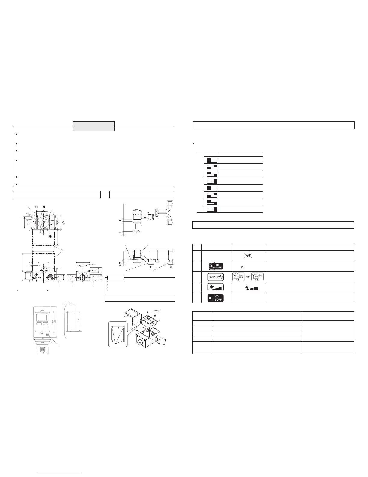
Unit (mm)
Outline Drawings
Trial Operation
Sample installation
Attention
After the product has been installed, carry out a trial operation.
If an error code should be flash, refer to the following table and take the required action.
1. Trial operation with the remote controller (PZ-45SLJ-E)
OA
(Outside air)
EA
(Exhaust air)
OA
(Outside air)
Hood or Louvre
(to prevent rain water
from seeping in)
Downward gradient of duct:
1/30 or more (toward wall side, provide 1m or more )
(to prevent rain water from seeping in)
EA
(Exhaust air)
RA
(Return air)
RA
(Return air)
SA
(
Supply air)
SA
(
Supply air)
Anchor bolt, nut
(Not included)
Supply air grille
(Not included)
Return air grille
(Not included)
Anchor bolt, nut
(Not included)
φ
200 Duct
(Not included)
Function setting
Configure the function setting using the function selection switch (SW-2) in the control box.
The setting can be changed at any time.
Configuring function selection switch (SW-2)
Ventilation stop by low SA temperature / high SA temperature and automatic recovery
When Lossnay detects low or high temperatures out of the
SA temperature setting range, it stops ventilation. Lossnay
checks the SA temperature every two hours. When it
detects a temperature within the setting range, it starts
operating again at the fan speed used before stopping.
※"STby"(Standby) is displayed on the remote controller if
Lossnay does not operate due to the above function.
※"Lo" is displayed on the remote controller when the
temperature is -10
℃ or lower.
OFF ON
SW2
Operation
7
8
Lossnay stops when the SA temperature is
detected 8
℃ or lower.
7
8
Lossnay stops when the SA temperature is
detected 10
℃ or lower.
7
8
Lossnay stops when the SA temperature is
detected 12
℃ or lower.
7
8
Invalid
9
10
9
10
9
10
9
10
Lossnay stops when the SA temperature is
detected 31
℃ or higher.
Lossnay stops when the SA temperature is
detected 28
℃ or higher.
Lossnay stops when the SA temperature is
detected 25
℃ or higher.
Invalid
Relevant button
Relevant display items
Sequence
1
2
3
4
5
Initiate the supply of power to the Lossnay unit. (The [HO]
display will flash for approximately 40 seconds)
Press the ON/OFF button. The Operation lamp will turn on and
the Lossnay unit will begin to operate.
Press the DISPLAY ℃button to select the display of SA or IA
temperature.
Press the Fan Speed Adjustment button to select low, middle,
or high fan speed.
Press the ON/OFF button. The Operation lamp will turn off and
the Lossnay unit will stop operating.
A circuit abnormality has occurred in the Lossnay unit.
Error code
4116
Cause Remedy
A breakdown has occurred in the Lossnay thermistor (OA side).
5101
A breakdown has occurred in the Lossnay thermistor (SA side).
5105
A breakdown has occurred in the remote controller thermistor.
Communication error
Turn off the power supply and
contact the retail outlet from
where this product was
purchased for further instructions.
Turn off the main switch and turn it
back on. If the error still continues,
contact the retail outlet.
5106
6608
- 2 - - 7 -
Built-in IA (Indoor Air) thermistor
Remote controller (included with the product)
Accessory parts
Mounting screw⋯×12 Duct connecting flange⋯×3
Control
box
EA
(exhaust air)
(supply air)
SA
(return air)
RA
(outside air)
OA
Air supply fan
Heat exchanger
(Lossnay core)
Air filter
Power cord opening
fixture
OA Maintenance cover
Air exhaust fan
Ceiling suspension
Maintenance
cover
Inspection space
420
184
262
871
30262
544
19
256
58
202
95
424
85
85
544
φ192
φ192
φ192
φ192
φ208
φ208
φ208
φ208
142
142
415
142
391
More than 700
More than 830
More than 600
How to remove the RA chamber form the Lossnay unit
The RA duct can be installed on the opposite side. Remove the RA chamber from the
unit by removing the screws, then rotate the RA chamber 180 degrees and reinstall.
Remove the RA chamber from the unit by removing the
mounting screws.
Maintenance
cover
Mounting
screw
Mounting
screw
RA chamber
RA chamber
Mounting screw
 Loading...