

Mitsubishi SEZ-KD18NA4, SEZ-KD12NA4, SEZ-KD15NA, SEZ-KD15NA4, SEZ-KD09NA Installation Guide
...Page 1
4F1k EL.ECTRIC
Air-Conditioners
SEZ-KD09,KD12,KD15,KD18NA
INSTALLATION MANUAL
For safe and correct use, please read this installation manual thoroughly before installing the air-conditioner
unit.
MANUEL D'INSTALLATION
Veuillez life le manuel d'installation en entier avant d'installer ce climatiseur pour eviter tout accident et vous
assurer d'une utilisation correcte.
Page 2
3
[Fig. 3-1]
3.1
(Unit: mm [in])
41
[Fig. 4-1]
@
D
5712-1/4 ]
@
(_ Access door
(_ Electrical parts box
(_©Air inlet
(_) Air outlet
(_) Ceiling surface
(F_)Service space (viewed from the side)
G(G)Service space (viewed from the direction of arrow)
Model A B C D E
SEZ-KD09 700[27-9/16] 752[29-5/8] 798[31-7/16] 660[26] 800[31-1/2]
SEZ-KD12,15 900135-7/16] 952137-1/2] 998139-5/16] 860133-7/8] 1000139-3/8]
SEZ-KD18 1100143-5/16]1152145-3/8]1198147-3/16]1060141-3/4]1200147q/4]
(_ Center of gravity
G 600 mm [23-5/8 in] or more
Q 100 mm [3-15/16 in] or more
@ 10 mm [13/32 in] or more
@ 300 mm [11-13/16 in] or more
(Unit: mm [in])
5__ 5.1 5.2
[Fig. 5-1] [Fig. 5-2]
©
[Fig. 5-3]
®
@ Unit © Nuts (field supplied)
(B_Lifting machine @ Washers (accessory)
(E_ M10 hanging bolt (field supplied)
(_ Indoor unit's bottom surface
2
Page 3
1 6.1
(Unit: mm [in])
[Fig. 6-1] _ _ 1_B
[Fig. 6-3]
@ Copper tubes @ Bad examples @ Uneven
@ Good example @ Tilted (_ Burred
[Fig. 6-6]
®
Ca_Flaring tool @ Flare nut
(_ Die Ce_Yoke
_ Copper tube
_) Indoor unit
@ Outdoor unit
[Fig. 6-4]
@ Burr @ Spare reamer
@ Copper tube/pipe @ Pipe cutter
[Fig. 6-7]
_) Smooth
@ Inside is shiny without
any scratches
@ Even length
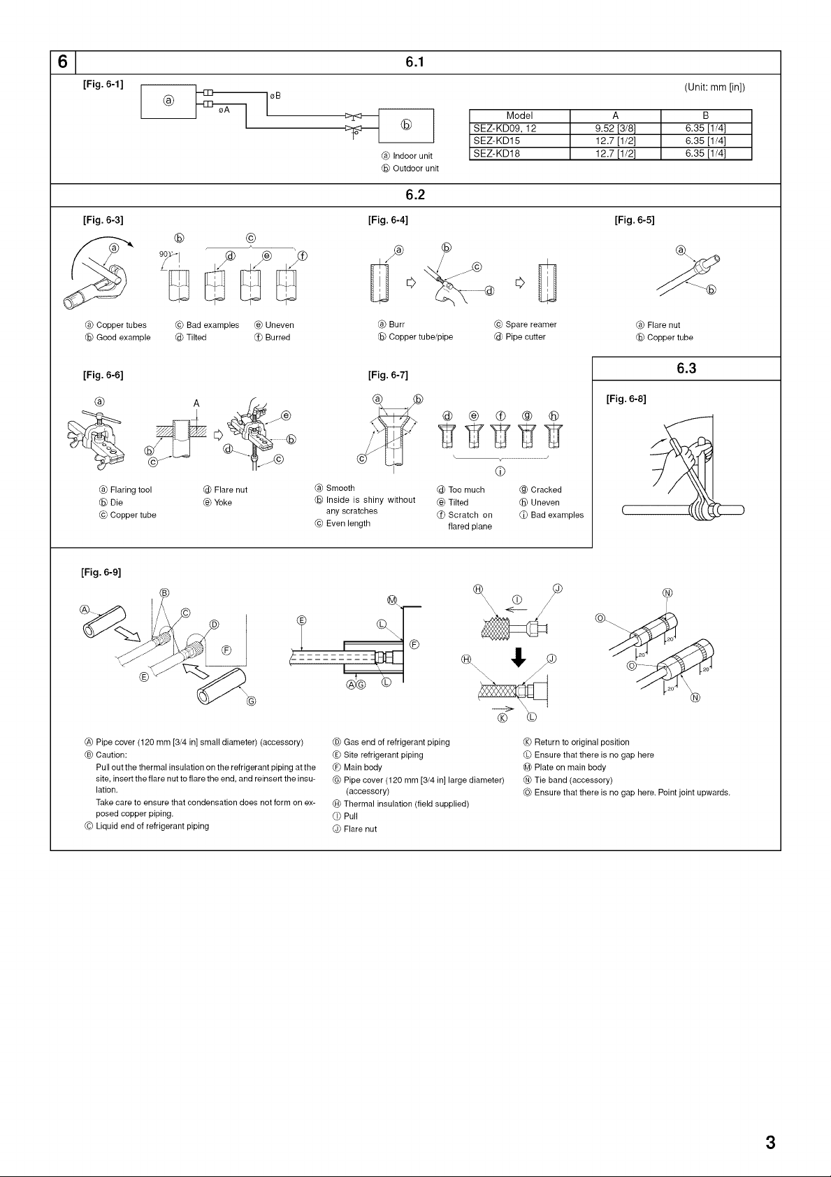
SEZ-KD09, 12 9.52 [3/8] 6.35 [1/4]
SEZ-KD15 12.7 [1/2] 6.35 [1/4]
SEZ-KD18 12.7 [1/2] 6.35 [1/4]
6.2
@
@ @ O @ ®
g' ggg
_ .........................................J
@
@ Too much @ Cracked
Ce_Tilted @ Uneven
(_ Scratch on _ Bad examples
flared plane
Model A B
[Fig. 6-5]
®
@ Flare nut
@ Copper tube
6.3
[Fig. 6-8]
[Fig. 6-9]
®
(_ Pipe cover (120 mm [3/4 in] small diameter) (accessory)
C_ Caution:
Pull out the thermal insulation on the refrigerant piping at the
site, insert the flare nut to flare the end, and reinsert the insu-
lation.
Take care to ensure that condensation does not form on ex-
posed copper piping.
Cc_Liquid end of refrigerant piping
@ Gas end of refrigerant piping
_E_Site refrigerant piping
_ Main body
@ Pipe cover (120 mm [3/4 in] large diameter)
(accessory)
(_ Thermal insulation (field supplied)
_) Pull
@ Flare nut
® ©
(_ Return to original position
CL_Ensure that there is no gap here
@ Plate on main body
Tie band (accessory)
@ Ensure that there is no gap here. Point joint upwards.
3
Page 4
6.5
[Fig. 6-10]
140 1.5_2m [5to 7ft] _L_C_
////Y/// ////1_// _v
////////////J //////// _
Max. 20m [65 ft]
x ,_ _x _'_
[Fig.6-11]
@
®
(Unit: mm [in])
b Correct piping
>4 Wrong piping
@ Insulation (9 mm [3/8 in] or more)
Downward slope (1/100 or more)
© Support metal
(_ Air bleeder
(_ Raised
@ Odor trap
Grouped piping
@ O. D. e32 mm [1-1/4 in] PVC TUBE
(E_Make it as large as possible. About 10 cm [3-15/16 in].
@DIndoor unit
(_ Make the piping size large for grouped piping.
(_ Downward slope (1/100 or more)
O. D.038 mm [1-1/2 in] PVC TUBE for grouped piping.
(9 mm [3/8 in] or more insulation)
@ Up to 550 mm [21-21/32 in]
(_) Drain hose (accessory)
@ Horizontal or slightly upward
[Fig.6-12]
®
@ Indoor unit
Pipe cover (60 mm [3/8 in]) (accessory)
© Tie band (accessory)
@ Visible part
(E_ Insertion margin
@DDrain hose (accessory)
(_ Drain pipe (O.D. 032 mm [1-1/4 in] PVC TUBE, field supplied)
(_ Insulating material (field supplied)
(_ Tie band (accessory)
(_J)Max.180 + 5 mm [7-3/32 + 7/32 in]
(_ No gap. The joint section of the insulation material must meet at the top.
[Fig. 6-13] [Fig. 6-14]
©
_) Insert pump's end 2 to 4 cm [13/16 to 1-19/32 in].
(_ Remove the water supply port.
(© About 2 liters
(_) Water
(_, Filling port
@_ Screw
<Indoor board>
(_) Indoor unit
(_ Pipe cover (30 mm [3/16 in]) (accessory)
© Tie band (accessory)
(_) Band fixing part
C_,Insertion margin
@_Drain hose (accessory)
Drain pipe (O.D. 032 PVC TUBE, field supplied)
(€1_Insulating material (field supplied)
Ci_Max.145 + 5 mm
6.6
SWE
4
Page 5
71
[Fig. 7-1]
®
8 8.1
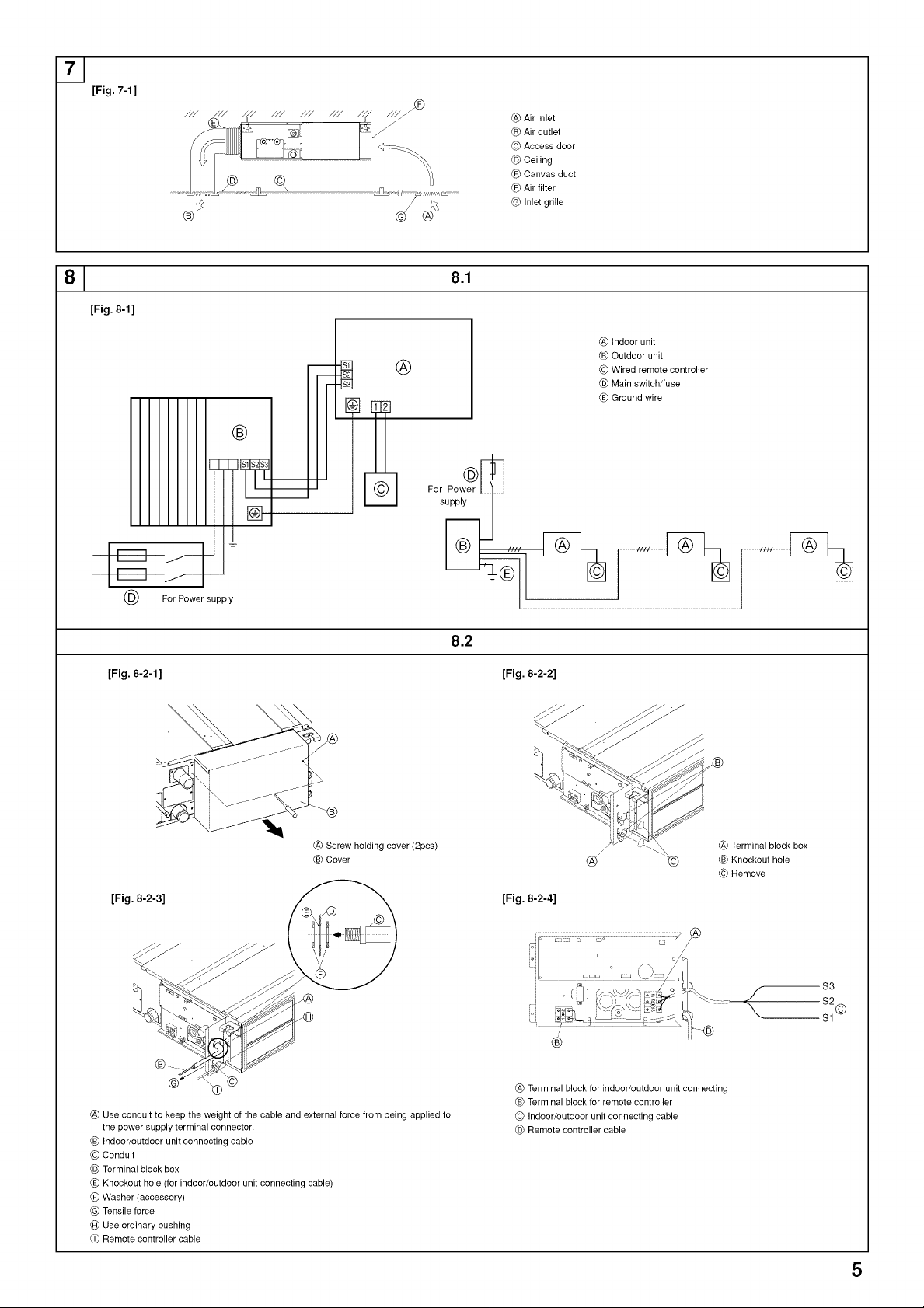
[Fig. 8-1]
®
(_ Air inlet
C_ Air outlet
C©Access door
(_) Ceiling
C_,Canvas duct
_ Air filter
G_ Inlet grille
@ Indoor unit
Outdoor unit
© Wired remote controller
@ Main switch/fuse
_E_Ground wire
For Power supply
8.2
[Fig. 8-2-1] [Fig. 8-2-2]
(8) Screw holding cover (2pcs) __ _ Terminal block box
C_ Cover (_ _ _ Knockout hole
[Fig. 8-2-3]
[Fig. 8-2-4]
_ i _ _ /_S _
© Remove
$3
®
(8) Use conduit to keep the weight of the cable and external force from being applied to
the power supply terminal connector.
C_ Indoor/outdoor unit connecting cable
© Conduit
(_) Terminal block box
C_,Knockout hole (for indoor/outdoor unit connecting cable)
_ Washer (accessory)
Tensile force
CH_Use ordinary bushing
Ci_Remote controller cable
(_ Terminal block for indoor/outdoor unit connecting
C_ Terminal block for remote controller
© Indoor/outdoor unit connecting cable
(_) Remote controller cable
5
Page 6
8 8.2
[Fig. 8-3]
@L-----J L_ b [AWG16] or more
(_ Indoor terminal block
Outdo o
@ Power supply cord
[Fig. 8-4]
__ CE;_ iUnit: mm [in])
(8) Indoor terminal block
C_ Ground wire (green/yellow)
Cc_Indoor/outdoor unit connecting cable 3-
core 1.5 mm 2 [AWG 16] or more
(_) Outdoor terminal block
C_,Power supply cord
O Indoor/outdoor unit connecting cable 3-
core 1.5 mm2 [AWG 16] or more, fol-
lowing Design 245 IEC 57.
(D Indoor terminal block
@ Outdoor terminal block
@ Always install an ground wire (1-core
8.3
(8) Remote controller
C_ Required clearances for the remote controller
Cc_Installation pitch
1.5 mm 2[AWG 16]) longer than other cables
@ Remote controller cable
Wire No x size (mm2) : Cable 2C × 0.3
Accessory wire of remote controller
(wire length : 10m [32 ft], non-polar. Max. 500 m
[1640 ft])
O Wired remote controller
(_ Power supply cord
[Fig. 8-5]
@ B-1.
®
@ For installation in the switch box:
CB_For direct installation on the wall, select one of the following:
• Prepare a hole through the wall to pass the remote controller cord (in order to run the remote controller cord from
the back), then seal the hole with putty.
• Run the remote controller cord through the cut-out upper case, then seal the cut-out notch with putty similarly as
above.
[Fig. 8-6]
(_ To the terminal block on the indoor unit
C_ TB6 (No polarity)
®
8.4
[Fig. 8-7]
C©Wall
(_) Conduit
C_,Lock nut
@_Bushing
Switch box
CA_Remote controller cord
Ci_Seal with putty
CJ_Wood screw
(_ Mode number
(_ Setting number
(_ Refrigerant address
(_ Unit number
(_ Filter .I button (<Enter> button)
C_ TEST button
&,
"_-',-_-I
6 4_
C©Set Time button
(_) Timer On/Off button (Set Day button)
C_,Mode selection button
_ Set temperature button
Timer Menu button (Monitor/Set button)
6
Page 7
91
[Fig. 9-1]
9.2 9.3
[Fig. 9-2]
©
_TEMP
@ ON/OFF button
Test run display
© Indoor temperature liquid line
temperature display
@ ON/OFF lamp
(E_ Power display
_ Error code display
Test run remaining time display
(_ Set temperature button
(_ Mode selection button
_) Fan speed button
@ TEST button
10 lO.1
[Fig. lO-1]
©
@ Indoor unit
Union
© Liquid pipe
@ Gas pipe
(E_ Stop valve
_ Outdoor unit
CG_Refrigerant gas cylinder operating valve
@ CHECK button
Refrigerant address
© TEME button
@ IC: Indoor unit
OC: Outdoor unit
(E_ Check code
(H_Refrigerant gas cylinder for R410A with
siphon
(i_ Refrigerant (liquid)
(J_)Electronic scale for refrigerant charging
(_ Charge hose (for R410A)
(L_Gauge manifold valve (for R410A)
@ Service port
7
Page 8
Contents
1. Safety precautions ................................................................................... 8
2. Selecting the installation location ............................................................. 8
3. Selecting an installation site & accessories ............................................. 9
4. Fixing hanging bolts ................................................................................. 9
5. Installing the unit ...................................................................................... 9
6. Refrigerant piping work .......................................................................... 10
7. Duct work ............................................................................................... 12
8. Electrical work ........................................................................................ 12
1. Safety precautions
Please report to or take consent by the supply authority before connection
to the system.
Be sure to read "The following should always be observed for safety" before
installing the air conditioner.
Be sure to observe the cautions specified here as they include important
items related to safety.
• The indications and meanings are as follows.
/_ Warning:
Could lead to death, serious injury, etc.
Z_ Caution:
Could lead to serious injury in particular environments when operated incor-
rectly.
After reading this manual, be sure to keep it together with the instruction
manual in a handy place on the customer's site.
z_ Warning:
• Do not install it by yourself (customer).
Incomplete installation could cause injury due to fire, electric shock, the unit
falling or leakage of water. Consult the dealer from whom you purchased the
unit or special installer.
• Install the unit securely in a place which can bear the weight of the unit.
When installed in an insufficient strong place, the unit could fall causing in-
jured.
• Use the specified wires to connect the indoor and outdoor units securely and
attach the wires firmly to the terminal board connecting sections so the stress
of the wires is not applied to the sections.
Incomplete connecting and fixing could cause fire.
• Do not use intermediate connection of the power cord or the extension cord
and do not connect many devices to one AC outlet.
It could cause a fire or an electric shock due to defective contact, defective
insulation, exceeding the permissible current, etc.
• Check that the refrigerant gas does not leak after installation has completed.
9. Test run .................................................................................................. 14
10. Maintenance .......................................................................................... 15
This Installation Manual only applies to the indoor unit and the SUZ series out-
door unit.
If the outdoor unit is MXZ series, refer to the Installation Manual for MXZ series.
Symbols put on the unit
: Indicates an action that must be avoided.
O: Indicates that important instructions must be followed.
O : Indicates a part which must be grounded.
z_: Indicates that caution should be taken with rotating parts.
: Indicates that the main switch must be turned off before servicing.
Z_ : Beware of electric shock.
z_ : Beware of hot surface.
Z_ Warning:
Carefully read the labels affixed to the main unit.
• Perform the installation securely referring to the installation manual.
Incomplete installation could cause a personal injury due to fire, electric shock,
the unit falling or leakage of water.
• Perform electrical work according to the installation manual and be sure to
use an exclusive circuit.
If the capacity of the power circuit is insufficient or there is incomplete elec-
trical work, it could result in a fire or an electric shock.
• Attach the electrical part cover to the indoor unit and the service panel to the
outdoor unit securely.
If the electrical part cover in the indoor unit and/or the service panel in the
outdoor unit are not attached securely, it could result in a fire or an electric
shock due to dust, water, etc.
• Be sure to use the part provided or specified parts for the installation work.
The use of defective parts could cause an injury or leakage of water due to a
fire, an electric shock, the unit falling, etc.
• Ventilate the room if refrigerant leaks during operation.
If the refrigerant comes in contact with a flame, poisonous gases will be re-
leased.
/_, Caution:
• Ground the unit.
Do not connect the ground wire to a gas pipe, water pipe arrester or telephone
ground wire. Defective grounding could cause an electric shock.
• Do not install the unit in a place where an inflammable gas leaks.
If gas leaks and accumulates in the area surrounding the unit, it could cause
an explosion.
• Install a ground leakage breaker depending on the installation place (where it
is humid).
If a ground leakage breaker is not installed, it could cause an electric shock.
2. Selecting the installation location
2.1. Indoor unit
• Where airflow is not blocked.
• Where cool air spreads over the entire room.
• Where it is not exposed to direct sunshine.
• At a distance 1 m [39-3/8 in] or more away from aTV and radio (to prevent picture
from being distorted or sound from being generated).
• In a place as far away as possible from fluorescent and incandescent lights (so the
infrared remote control can operate the air conditioner normally).
2.2. Outdoor unit
• Where it is not exposed to strong wind.
• Where airflow is good and dustless.
• Where it is not exposed to rain and direct sunshine.
• Where neighbours are not annoyed by operation sound or hot air.
• Where rigid wall or support is available to prevent the increase of operation sound
or vibration.
• Where there is no risk of combustible gas leakage.
• When installing the unit at a high level, be sure to fix the unit legs.
• Where it is at least 3m [10 ft] away from the antenna of TV set or radio. (Otherwise,
images would be disturbed or noise would be generated.)
• Perform the drainage/piping work securely according to the installation
manual,
If there is a defect in the drainage/piping work, water could drop from the unit
and household goods could be wet and damaged,
• Fasten a flare nut with a torque wrench as specified in this manual,
When fastened too tight, a flare nut may broken after a long period and cause
a leakage of refrigerant,
• Where the air filter can be removed and replaced easily.
Warning:
Mount the indoor unit into a ceiling strong enough to withstand the weight of
the unit.
• Install the unit horizontally.
Z_ Caution:
Avoid the following places for installation where air conditioner trouble is li-
able to occur.
• Where there is too much machine oil in the air.
• Salty environments as seaside areas.
• Hot-spring areas.
• Where sulfide gas exists.
• Other special atmospheric areas.
8
Page 9

3. Selecting an installation site & accessories
• Select a site with sturdy fixed surface that is strong enough to support the weight of
unit.
• Before installing unit, the routing to carry in unit to the installation site should be
determined.
• Select a site where the unit is not affected by entering air.
• Select a site where the flow of supply and return air is not blocked.
• Select a site where refrigerant piping can easily be installed to the outside.
• Select a site which allows the supply air to be fully distributed in a room.
• Do not install unit at a site near a lot of oil or steam.
• Do not install unit at a site where combustible gas may generate, flow in, stagnate
or leak.
• Do not install unit at a site where there is equipment generating high frequency
waves (a high frequency wave welder for example).
• Do not install unit at a site where fire detector is located at the supply air side. (Fire
detector may operate erroneously due to the heated air supplied during heating
operation.)
• If there are chemicals in the area, such as chemical plants and hospitals, full inves-
tigation is required before installing unit. (The plastic components may be dam-
aged depending on the chemical product applied.)
• If the unit runs for long hours when the air above the ceiling is at high temperature/
high humidity (due point above 79 °F [26 °C]), condensation may be produced in
the indoor unit. Add insulation material (10-20 mm [13/32 to 13/16 in]) to the entire
surface of the indoor unit to avoid condensation.
3.1. Install the indoor unit on a ceiling strong enough
to sustain its weight
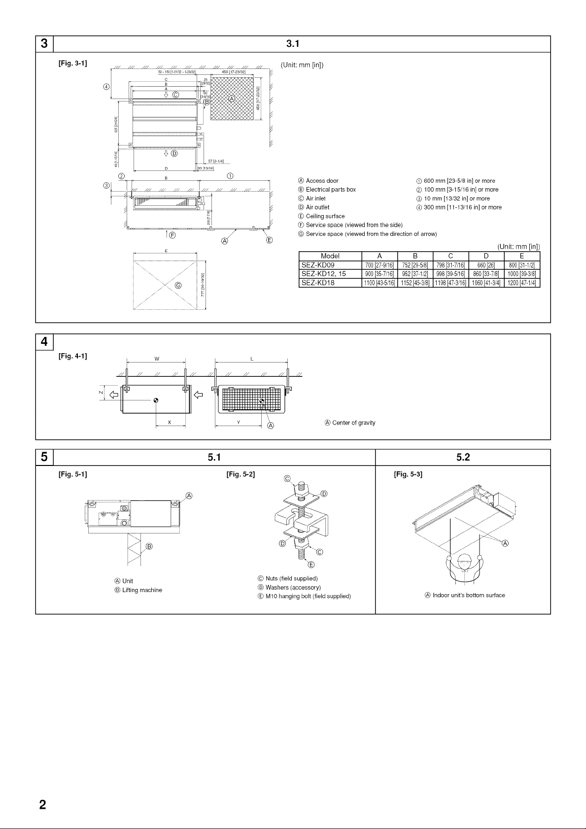
[Fig. 3-1] (P.2)
@ Access door (_ Electrical parts box
© Air inlet (_)Air outlet
(E_Ceiling surface @_Service space (viewed from the side)
(_ Servicespace (viewed from the direction of arrow)
(_ 600 mm[23-5/8 in] or more (D 100mm [3-15/16 in] or more
Q 10 mm [13/32 in] or more @ 300mm [11-13/16 in] or more
/_ Warning:
The unit must be securely installed on a structure that can sustain its weight. If
the unit is mounted on an unstable structure, it may fall down, causing injuries.
3.2. Securing installation and service space
• Select the optimum direction of supply airflow according to the configuration of the
room and the installation position.
• As the piping and wiring are connected at the bottom and side surfaces, and the
maintenance is made at the same surfaces, allow a proper space properly. For the
efficient suspension work and safety, provide a space as much as possible.
3.3. Outdoor unit
Ventilation and service space
Units should be installed by licensed contractor accordingly to local code require-
ments.
For outdoor units to be connected, refer to the Installation Manual that comes with
the units.
3.4. Indoor unit accessories
The unit is provided with the following accessories:
No. Name Quantity
Q Pipecover (forrefrigerant pipingjoint) 120 mm [3/4 in] Small diameter 1
Q Pipecover (forrefrigerant pipingjoint) 120 mm [3/4 in] Large diameter 1
Q Tie band 7
(_ Remote controller parts 1
@ Remote controller cable 1
@ Washer (for hanging) 8
Q Drain hose 1
Q Pipe cover (for Drain hose) 60 mm [3/8 in] 1
@ Pipe cover (for Drain hose) 30 mm [3/16 in] 1
@ Washer (for power source wiring) 2
4. Fixing hanging bolts
4.1. Fixing hanging bolts
[Fig. 4-1] (P.2)
@ Centerof gravity
Hanging structure
• Ceiling:The ceiling structure varies from building to one another. For detailed infor-
mation, consult the construction company.
Center of gravity and Product Weight
Model name
SEZ-KD09
SEZ-KD12
SEZ-KD15
SEZ-KD18
W (mm [in]) L (mm [in]) X (mm [in]) Y (mm [in]) Z (mm [in]) Product Weight (kg [Ib])
625 [24-5/8] 752 [29-5/8] 263 [10-3/8] 351 [13-27/32] 106 [4-3/16] 19 [42]
625 [24-5/8] 952 [37-1/2] 286 [11-9/32] 448 [17-21/32] 104 [4-1/8] 22 [50]
625 [24-5/8] 952 [37-1/2] 280 [11-1/32] 437 [17-7/32] 104 [4-1/8] 24 [54]
625 [24-5/8] 1152 [45-3/8] 285 [11-1/4] 527 [20-3/4] 104 [4-1/8] 28 [62]
5. Installing the unit
5.1.
Hanging the unit
I,
Transport the indoor unit to the site in its original packing material.
I,
To hang the indoor unit, use a lifting machine to lift and pass through the
hanging bolts.
[Fig. 5-1] (P.2)
@ Unit
@ Lifting machine
[Fig. 5-2] (P.2)
© Nuts (field supplied)
@ Washers (accessory)
(E_M10hanging bolt (fieldsupplied)
• If necessary, reinforce the hanging bolts to protect against earthquakes.
* Use M10 for hanging bolts and reinforcements to protect against earthquake
(field supplied).
(_) Ceiling reinforcement (edge beam, etc.) must be required to keep the ceiling level
and to prevent it from vibrating.
(D Cut and remove the ceiling beams.
(_ Reinforce the ceiling, and add other beams for fixing the ceiling boards.
5.2. Confirming the unit's position and attaching hang-
ing bolts
Use the gauge supplied with the panel to confirm that the unit and hanging
bolts are positioned in place. If they are not positioned in place, it may
condensated due to drafts. Be sure to check the position.
Use a level to check that the surface indicated by @ is straight. Ensure that
the hanging bolt nuts are tightened to fix the hanging bolts.
To ensure that drain is discharging properly, be sure to hang the unit is
straight using a level.
[Fig. 5-3] (P.2)
_) Indoorunit's bottomsurface
Z_ Caution:
Be sure to install the unit level.
9
Page 10

6. Refrigerant piping work
6.1. Refrigerant pipe
[Fig. 6-1] (P.3)
Ca_Indoorunit
@ Outdoor unit
Refer to the outdoor unit Instruction Manual for restrictions on
the height difference between units and for the amount of additional refrigerant
charge.
Avoid the following places for installation where the air conditioner malfunction is
liable to occur.
Where there is too much oil in the air such as for machines or cooking.
Salty environments as seaside areas.
Hot-spring areas.
Where sulfide gas exists.
Other special atmospheric areas.
This unit has flared connections on both indoor and outdoor sides. (Fig. 6-1)
Refrigerant pipes are used to connect the indoor and outdoor units as shown inthe
figure below.
• Insulate both refrigerant and drainage piping completely to prevent condensation.
Piping preparation
• Refrigerantpipes 3, 5, 7, 10 and 15 m [5 ft] are availableas optional items.
(1) The specifications of commercially available pipes.
Model Pipe
SEZ- For liquid 6.35 1/4 0.8rnm[1/16in] 8mm[11/32in]
KD09 For gas 9.52 3/8 0.8rnm[1/16in] 8mm[11/32in]
SEZ- For liquid 6.35 1/4 0.8rnm[1/16in] 8mm[11/32in]
KD 12 For gas 9.52 3/8 0.8rnm[1/16in] 8mm[11/32in]
SEZ- For liquid 6.35 1/4 0.8rnm[1/16in] 8mm[11/32in]
KD15 For gas 12.7 1/2 0.8rnm[1/16in] 8mm[11/32in]
SEZ- For liquid 6.35 1/4 0.8rnm[1/16in] 8mm[11/32in]
KD 18 For gas 12.7 5/8 1.0rnm[1/16in] 8mm[11/32in]
Outside diameter Min wall Insulation
mm inch thickness thickness
Insulation
material
Heat-resistant
foam plastic,
0.045 specific
gravity
6.2.3. Putting nut on
[Fig. 6-5] (P.3)
Ca_Flare nut
@ Copper tube
• Remove flare nuts attached to indoor and outdoor unit, then attach them on pipe/
tube after burr removal.
(not possible to attach them on after flaring work)
6.2.4. Flaring work
[Fig. 6-6] (P.3)
Ca_Flaringtool
(_ Die
_ Copper tube
@ Flare nut
Yoke
• Carry out flaring work using flaring tool as shown below.
Dimension
Pipe diameter
(mm [in]) B -+°4[-u32](mm [in])
6.35 [1/4] 9.1 [3/8]
9.52 [3/8] 13.2 [17/32]
12.7 [1/2] 16.6 [21/32]
15.88 [5/8] 19.7 [25/32]
Firmly hold copper tube in a die in the dimension shown in the table at above.
6.2.5. Check
[Fig. 6-7] (P.3)
(_ Smooth (_ Scratch on flared plane
@ Insideis shiny withoutany scratches @ Cracked
@ Even length @ Uneven
@ Toe much (D Badexamples
@_Tilted
• If flare is defective, cut off the flared section and repeat.
When the tool for R410A is used
A (ram [in])
Clutch type
0 to 0.5 [0 to 1/32]
0 to 0.5 [0 to 1/32]
0 to 0.5 [0 to 1/32]
0 to 0.5 [0 to 1/32]
(2) Ensure that the two refrigerant pipes are well insulated to prevent condensation.
(3) Refrigerant pipe bending radius must be 10 cm [3-15/16 in] or more.
/_, Caution:
Use insulation of specified thickness. Excessive thickness prevents storage
behind the indoor unit and smaller thickness causes condensation.
6.2. Flaring work
• Main cause of gas leakage is defect in flaring work.
Carry out correct flaring work in the following procedure.
6.2.1. Cutting the pipes
[Fig. 6-3] (P.3)
Ca_Copper tubes
(_)Goodexample
_ Badexamples
@ Tilted
_e_Uneven
(_ Burred
• Use a pipe cutter cut the copper tube correctly.
6.2.2. Burr removal
[Fig. 6-4] (P.3)
Ca_Burr
(_)Coppertube/pipe
_ Spare reamer
@ Pipecutter
• Completely remove all burrs from the cut section of pipe/tube.
• Point the end of the copper tube/pipe to downward direction as you remove burrs in
order to avoid burrs drop in the tubing.
6.3. Pipe connection
[Fig. 6-8] (P.3)
• Apply a thin coat of refrigeration oil on the surface of pipe.
• When connecting, first align the center, then tighten the flare nut 3 to 4 turns.
• Use tightening torque table below as a guideline for indoor unit side union joint section,
and tighten using two wrenches. Excessive tightening damages the flare section.
Copper pipe O.D.
(mm [in])
66.35 [1/4]
69.52 [3/8]
612.7 [1/2]
615.88 [5/8]
Z_ Warning:
Be careful of removing the flare nut! (Internally pressurize can cause them to
burst off.)
Remove the flare nut as follows:
1. Loosen the nut until you hear a hissing noise.
2. Do not remove the nut until the gas has been completely released (i.e., hiss-
ing noise stops).
3. Check that the gas has been completely released, and then remove the nut.
Outdoor unit connection
Connect pipes to stop valve pipe joint of the outdoor unit following the same proce-
dure as the indoor unit.
• For tightening, use a torque wrench or spanner, and use the same tightening torque
procedure for indoor unit.
Flare nut O.D. Tightening torque
(mm [in]) (N.m)
17 [11/16] 14- 18
22 [7/8] 34- 42
26 [1-1/32] 49- 61
29 [1-5/32] 68- 82
10
Page 11

6. Refrigerant piping work
Refrigerant pipe insulation
• After connecting refrigerant piping, insulate the joints (flared joints) with thermal
insulation tubing as shown below.
[Fig. 6-9] (P.3)
@ Pipecover (120 mm [3/4 in]small diameter) (accessory)
_B_Caution:
Pullout thethermal insulationon the refrigerant pipingat the site,insertthe flarenut toflare
the end,and reinsertthe insulation.
Takecare to ensure thatcondensation does notform on exposed copper piping.
© Liquidend of refrigerant piping
@ Gasend of refrigerant piping
(E_Site refrigerant piping
@_Mainbody
(_ Pipecover (120 mm [3/4 in] large diameter) (accessory)
(_ Thermal insulation (fieldsupplied)
(_ Pull
@ Flare nut
(_ Returnto original position
(_ Ensurethat there is no gap here
@ Plate on mainbody
(_) Tie band (accessory)
@ Ensurethat there is no gap here. Point joint upwards.
1.Remove and discard the rubber bung which is inserted in the end of the unit piping.
2.Flare the end of the refrigerant piping.
3.Remove the thermal insulation on the site refrigerant piping and replace the insula-
tion in its original position.
Cautions On Refrigerant Piping
Be sure to use non-oxidized brazing for brazing to ensure that foreign mat-
ter or moisture do not enter into the pipe.
Be sure to apply refrigerating machine oil over the flare connection seating
surface and tighten the connection using a double spanner.
Provide a metal brace to support the refrigerant pipe so that no load is
imparted to the indoor unit end pipe.This metal brace should be provided
50 cm [19-11/16 in] away from the indoor unit's flare connection.
6.4. Purging procedures leak test
( PURGING PROCEDURES 1
*Close
Stop valve
*Open
Hexagonal wrench *4 to 5 turns
-0.10IMPs Compound pressure gauge
Stop valve (-760 mmHg) (for R410A)
_ , Pressure gauge
,F_S_ "_ / (for R410A)
Ill[ _ _ _ Gauge manifold
./
IIL ,,_ _valve (for R410A)
II Ij,_ffJ-'_ Handle2, Handle High
_ll_,__-_k Low ///7 _ Charge hose (for
_" \X Stop /j/ _,.=.. R410A)
. ./ \\valve J/ / ' va_u_ (or the vacuum
Service _ / i_'"1 numn wth th_
oft -- • - _ r-...r .......
P ,,7 Wmaow f'b'rrrz¢_7" function to prevent
Charge hose Ada)ter for the back flow)
(for R410A) preventing the
back flow
l
['Remove the gage manifold valve quickly from the service port of the stop valve.
l
After refrigerant pipes are connected and evacuated, fully open all stop valves on']
gas and liquid pipe sides. |
Operating without fully opening lowers the performance and causes trouble. )
1
7 m [23 ft] maximum Charge the prescribed
I Pipe length : 1 [ Pipe length exceeding 7 m [23 ft] l
No gas charge is needed, amount of gas.
1
Connect the refrigerant pipes (both the liquid and gas pipes) between the indoor"
and the outdoor units.
l
Remove the service port cap of the stop valve on the side of the outdoor unit gas pipe."
(The stop valve will not work in its initial state fresh out of the factory (totally closed
with cap on).) .,
l
Connect the gage manifold valve and the vacuum pump to the service port of the"
stop valve on the gas pipe side of the outdoor unit.
l
(Run the vacuum pump. (Vacuumize for more than 15 minutes.)
!
Check the vacuum with the gage manifold valve, then close the gage manifold valve,_
and stop the vacuum pump. )
1
Leave it as is for one or two minutes. Make sure the pointer of the gage manifold']
valve remains in the same position. Confirm that the pressure gage show -0.101 MPa|
(-760 mmHg). J
l
4,
(
(
(
6.5. Drain piping work
• Ensure that the drain piping is downward (pitch of more than 1/100) to the outdoor
• Ensure that any cross drain piping is less than 20 m [65 ft] (excluding the differ-
• Use a hard vinyl chloride pipe O.D. e32 mm [1-1/4 in] for drain piping.
• Ensure that collected pipes are 10 cm [3-15/16 in] lower than the unit body's drain
• Do not provide any odor trap at the drain discharge port.
• Place the end of the drain piping in a position where odor is not generated.
• Do not put the end of the drain piping in any drain where ionic gases are generated.
Grouped piping
Tighten the cap to the service port to obtain the initial status. )
Retighten the cap )
Leak test )
(discharge) side. Do not add a trap.
ence of elevation). If the drain piping is long, add metal braces to prevent it from
shaking. Never provide an air vent pipe, otherwise drain may be ejected.
port.
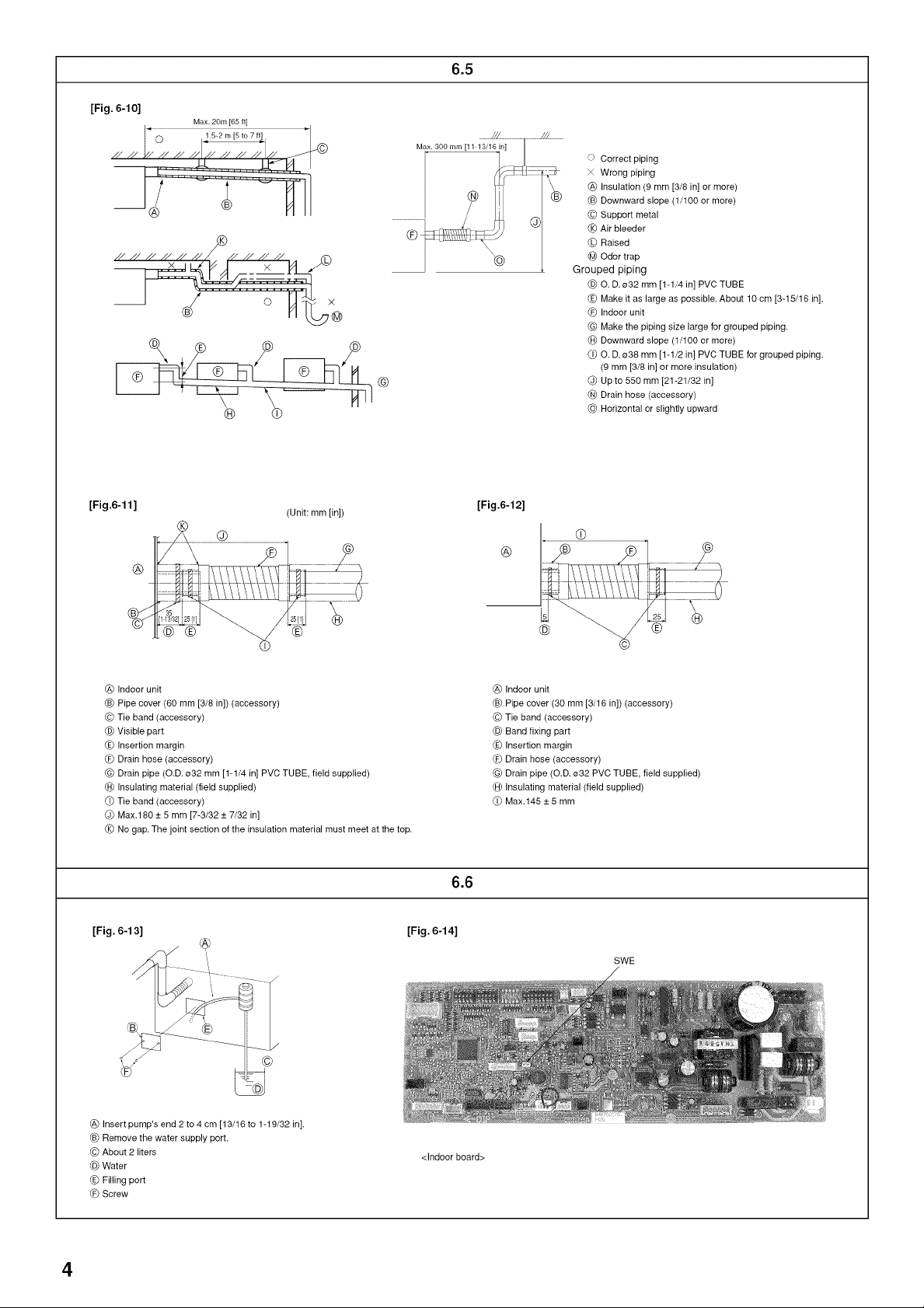
[Fig. 6-10] (P.4)
c Correct piping
x Wrong piping
@ Insulation (9 mm [3/8in] or more)
Downward slope (1/100 or more)
© Support metal
(_ Air bleeder
(_ Raised
@ Odor trap
@ O. D. o32 mm [1-1/4 in] PVC TUBE
(E_Make itas large as possible. About 10 cm [3-15/18 in].
@_Indoorunit
(_ Makethe pipingsize largefor grouped piping.
(_ Downward slope (1/100 or more)
O. D.038 mm[1-1/2 in] PVC TUBEfor groupedpiping.
(9 mm [3/8 in] or more insulation)
@ Up to 550 mm [21-21/32 in]
(_)Drain hose (accessory)
@ Horizontal or slightly upward
11
Page 12

6. Refrigerant piping work
1. Insert the drain hose (accessory) into the drain port (insertion margin: 25 mm
[1 in]).
(The drain hose must not be bent more than 45 ° to prevent the hose from break-
ing or clogging.)
(Attach the hose with glue for the hard vinyl chloride pipe, and fix it with the band
(accessory).)
2. Attach the drain pipe (O.D. o32 mm [1-1/4 in] PVC TUBE, field supplied).
(Attach the pipe with glue for the hard vinyl chloride pipe, and fix it with the band
(accessory).)
3. Perform insulation work on the drain pipe (O.D. 032 mm [1-1/4 in] PVC TUBE)
and on the socket (including elbow).
4. Check the drainage. (Refer to [Fig. 6-13])
5. Attach the insulating material (accessory), and fix it with the band (accessory) to
insulate the drain port.
[Fig. 6-11] (R4)
_) Indoorunit
(_ Pipecover (60 mm [3/8 in]) (accessory)
(© Tie band(accessory)
(_)Visiblepart
_, insertion margin
@_Drain hose (accessory)
G(_Drain pipe (O.D.032 mm [1-1/4 in] PVC TUBE, field supplied)
(€1_Insulating material (field supplied)
(i_ Tie band(accessory)
(J_)Max.180+ 5 mm[7-3/32 + 7/32 in]
(_ Nogap.The joint of the insulation material must meet atthe top.
[Drainage by gravity]
1. Insert the drain hose (accessory) into the drain port.
(The drain hose must not be bent more than 45 ° to prevent the hose from breaking
or clogging.)
The connecting part between the indoor unit and the drain hose may be discon-
nected at the maintenance. Fix the part with the accessory band, not be adhered.
2. Attach the drain pipe (O.D. e32 PVC TUBE, field supplied).
(Attach the pipe with glue for the hard vinyl chloride pipe, and fix it with the band
(accessory).)
3. Perform insulation work on the drain pipe (O.D. e32 PVC TUBE) and on the socket
(including elbow).
7. Duct work
[Fig. 6-12] (P.4) * Drainage by gravity
(_) Indoor unit
(_ Pipe cover (30 mm [3/16 in]) (accessory)
© Tie band (accessory)
(_) Band fixing part
<_, Insertion margin
@_ Drain hose (accessory)
G(_Drain pipe (O.D. 032 PVC TUBE, field supplied)
(€1_Insulating material (field supplied)
(i_ Max. 145+ 5 mm
6.6. Confirming drain discharge
b' Make sure that the drain-up mechanism operates normally for discharge
and that there is no water leakage from the connections.
• Be sure to confirm the above when in heating operation.
• Be sure to confirm the above before ceiling work is done in the case of a new
construction.
1. Remove the water supply port cover on the same side as the indoor unit piping.
2. Fill water into the feed water pump using a feed water tank. Be sure to put the end
of the pump or tank in a drain pan. (If the insertion is incomplete, water may flow
over the machine.)
3. Perform the test run in cooling mode, or turn on the switch SWE on the controller
circuit board. (The drain pump and the fan are forced to operate without any re-
mote controller operation.) Make sure using a transparent hose that drain is dis-
charged. SWE SWE
ON OFF ON OFF
4. After confirmation, cancel the test run mode, and turn off the main power. When
the switch SWE has been turned on, turn it off, and attach the water supply port
cover into its original position.
[Fig. 6-13] (P.4)
(_ Insertpump's end 2to 4 cm [13/16 to 1-19/32 in].
_ Removethe water supply port.
© About 2000 liters
(_)Water
<_,Filling port
@_Screw
[Fig. 6-14] (P.4)
<Indoor board>
SWE SWE
liTir-I ---. I-lilil
ON OFF ON OFF
• When connecting ducts, insert a canvas duct between the main body and the duct.
• Use non-combustible duct components.
/_ Caution:
The sound from the intake will increase dramatically if intake (_) is fitted
directly beneath the main body. Intake @ should therefore be installed as
far away from the main body as possible.
Particular care is required when using it with bottom inlet specifications.
Install sufficient thermal insulation to prevent condensation forming on
outlet duct flanges and outlet ducts.
To connect the air conditioner main body and the duct for potential equali-
zation.
8. Electrical work
8.1. Power supply
Electrical specification Input capacity Main Switch/Fuse (A)
Power supply SEZ-KD09 SEZ-KD12 SEZ-KD15 SEZ-KD18
(1 phase _/N, 208/230V, 60Hz 10 10 20 20
Z_ Warning:
• The compressor will not operate unless the power supply phase connection
is correct.
• Ground protection with a no-fuse breaker (ground leakage breaker) is usu-
ally installed for (!_).
• The connection wiring between the outdoor and indoor units can be extended
up to a maximum of 50 m [164 ft], and the total extension including the crosso-
ver wiring between rooms is a maximum of 80 m [262 ft].
Provide switch with at least 3 mm [1/8 in] contact separation in each pole.
* Label each breaker according to purpose (heater, unit etc.).
[Fig. 8-1] (P.5)
(_ Indoorunit _B_Outdoorunit
(© Wired remote controller @ Mainswitch/fuse
(_)Groundwire
The distance between the inlet grille and the fan should be at least over 850
mm [33-15/32 in] or more.
If it is less than 850 mm [33-15/32 in], install a safety guard so the fan can-
not be easily accessed.
[Fig. 7-1] (P.5)
(_) Air inlet
(_ Air outlet
© Access door
(_) Ceiling
<_,Canvas duct
@_Air filter
G(_Inlet grille
8.2. Indoor wire connection
Work procedure
1. Remove two screws to detach the electric component cover.
2. Route each cable through the wiring intake into the electric component box. (Pro-
cure power cable and in-out connecting cable locally and use remote control cable
supplied with the unit.)
3. Securely connect the power cable and the in-out connecting cable and the remote
control cable to the terminal blocks.
4. Secure the cables with clamps inside the electric component box.
5. Reattach the electric component cover.
• Attach power supply cable and indoor/outdoor cable to control box by using buffer
bushing for tensile force. (PG connection or the like.)
Warning:
• Attach the electrical part cover securely. If it is attached incorrectly, it could
result in a fire or electric shock due to dust, water, etc.
• Use the specified indoor/outdoor unit connecting wire to connect the indoor
and outdoor units. Attach the wire to the terminal block securely so that stress
is not applied to the terminal block connection. Incomplete connection or
fixing of the wire could result in a fire.
12
Page 13

8. Electrical work
[Fig. 8-2-1] (P.5)
@ Screw holding cover (2pcs)
_B_Cover
[Fig. 8-2-2] (P.5)
@ Terminal block box
Knockout hole
© Remove
[Fig. 8-2-3] (P.5)
@ Use conduit to keep the weight of the cable and external force from being applied to the
power supply terminal connector.
Indoor/outdoor unit connecting cable
© Conduit
@ Terminal block box
(E_ Knockout hole (for indoor/outdoor unit connecting cable)
@_ Washer (accessory)
(_ Tensile force
O Use ordinary bushing
Remote controller cable
[Fig. 8-2-4] (P.5)
@ Terminal block for indoor/outdoor unit connecting
Terminal block for remote controller
© Indoor/outdoor unit connecting cable
@ Remote controller cable
• Perform wiring as shown in the diagram to the lower left. (Procure the cable lo-
cally.)
Make sure to use cables of the correct polarity only.
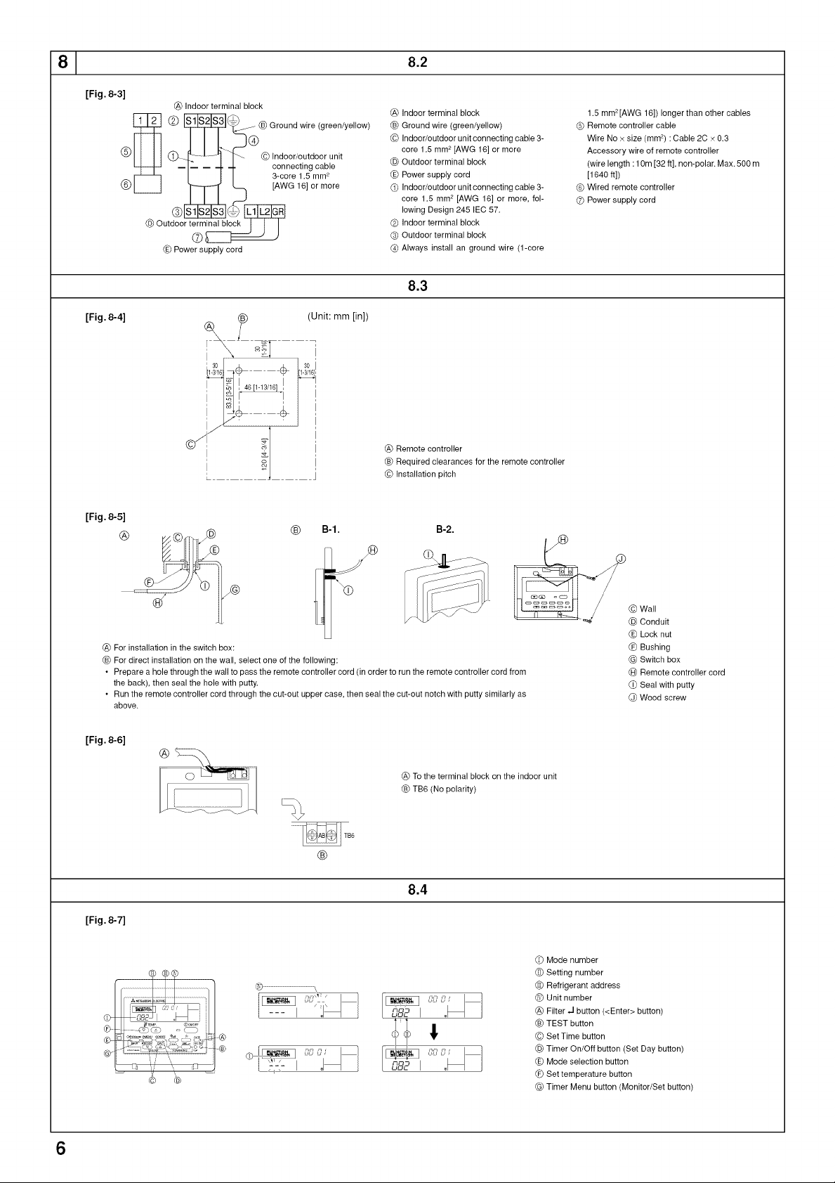
[Fig. 8-3] (P.6)
@ Indoor terminal block
Ground wire (green/yellow)
© Indoor/outdoor unit connecting cable 3-core 1.5 mm 2 [AWG 16] or more
@ Outdoor terminal block
(E_ Power supply cord
(_ Indoor/outdoor unit connecting cable 3-core 1.5 mm 2[AWG 16] or more, following Design
245 IEC 57.
(_ Indoor terminal block
@ Outdoor terminal block
@ Always install an ground wire (1-core 1.5 mm 2 [AWG 16]) longer than other cables
(_ Remote controller cable
Wire No × size (mm 2) : Cable 2C x 0.3
Accessory wire of remote controller
(wire length : 10 m [32 ft], non-polar. Max. 500 m [1640 ft])
G Wired remote controller
G Power supply cord
• Connect the terminal blocks as shown in the diagram below.
Z_ Caution:
• Conduct electrical work properly.
• Firmly tighten the terminal screws to prevent them from loosening.
• After tightening, pull the wires lightly to confirm that they do not move.
8.3. Remote controller
8.3.1. For wired remote controller
1) Installing procedures
(1) Select an installing position for the remote controller.
The temperature sensors are located on both remote controller and indoor unit.
Procure the following parts locally:
Two piece switch box
Thin copper conduit tube
Lock nuts and bushings
[Fig. 8-4] (P.6)
@ Remotecontroller
Required clearancesfor the remote controller
© Installationpitch
(2) Seal the service entrance for the remote controller cord with putty to prevent pos-
sible invasion of dew drops, water, cockroaches or worms.
[Fig. 8-5] (P.6)
@ Forinstallation inthe switch box:
_B_For direct installationon the wall,select oneof the following:
• Preparea holethrough the wallto passthe remotecontrollercord (in orderto run the remote
controller cord from the back), then seal the hole withputty,
• Run the remote controller cord through the cut-out upper case, thenseal the cut-out notch
with putty similarly as above.
© Wall G(_Switch box
@ Conduit (A_Remote controller cord
(E_Locknut (i_ Seal with putty
@_Bushing (3pWoodscrew
B-1. To lead the remote controller cord from the back of the controller:
B-2. To run the remote controller cord through the upper portion:
(3) For direct installation on the wall
2) Connecting procedures
(_) Connect the remote controller cord to the terminal block.
[Fig. 8-6] (P.6)
@ Tothe terminal block on the indoor unit
(B_TB6 (Nopolarity)
(D Set the dip switch No.1 shown below when using two remote controller's for the
same group.
3) Selecting the remote controller function
If two remote controllers are connected, set one to "Main" and the other to "Sub". For
setting procedures, refer to "Function selection of remote controller" in the operation
manual for the indoor unit.
8.4. Function settings (Function selection via the re-
mote controller)
Refer to the manual that came with the remote controller for setting procedure and
operation method.
8.4.1 Function setting on the unit (Selecting the unit functions)
1) Changing the external static pressure setting [Fig. 8-7] (P.6)
• Be sure to change the external static pressure setting depending on the duct and
the grill used.
(_) Go to the function setting mode.
Switch OFF the remote controller.
Press the @ and (_) buttons simultaneously and hold them for at least 2
seconds. FUNCTION will start to flash.
(D Use the © button to set the refrigerant address (HI) to 00.
(_ Press @ and [--] will start to flash in the unit number (IV) display.
(_ Use the © button to set the unit number (_T) to 01-04 or AL.
O Press the (_ MODE button to designate the refrigerant address/unit number.
[--] will flash in the mode number ( [ ) display momentarily.
O Press the (_ buttons to set the mode number ( _ ) to 08.
(_ Press the @ button and the current set setting number ([J[) will flash.
Use the (_ button to switch the setting number in response to the external static
3ressure to be used.
External static Setting no. of mode Setting no. of mode
pressure no. 08 no. 10
5 Pa (0.02 in.WG) 1 2
15 Pa (0.06 in.WG) 1 1
(before shipment)
35 Pa (0.14 in.WG) 2 1
50 Pa (0.20 in.WG) 3 1
O Press the MODE button (_ and mode and the setting number ( _ ) and ( L[ ) will
change to being on constantly and the contents of the setting can be confirmed.
@ Press the FILTER @ and TEST RUN (_) buttons simultaneously for at least two
seconds. The function selection screen will disappear momentarily and the air
conditioner OFF display will appear.
O To set the static pressure at 5Pa (0.02 in.WG), repeat steps (_ to @. (Set the
mode number to 10 for step O.)
2) Other functions
(_) Select unit number 00 for the settings. (Settings for all indoor units)
Refer to Function table 1.
(D Select unit number 01 to 04 or AL for the settings. (Settings for each indoor unit)
To set the indoor unit in the individual system, select unit number 01.
To set each indoor unit of two, three or four indoor units, which are connected
when these units are simultaneously in operation, select unit number 01 to 04.
To set all indoor units of two, three or four indoor units which are connected when
these units are simultaneously in operation, select AL.
Refer to Function table 2.
13
Page 14

8. Electrical work
Function table 1
Select unit number 00
Mode
Power failure automatic recovery*l
(AUTO RESTART FUNCTION)
Indoor temperature detecting
LOSSNAY connectivity
Function table 2
Select unit numbers 01 to 04 or all units (AL [wired remote controller]/07 [wireless remote controller])
Mode Settings
Filter sign 100 Hr
External static pressure 15 Pa (0.06 in.WG)
"1 When the power supply returns, the air conditioner will start 3 minutes later.
Note: When the function of an indoor unit were changed by function selection after the end of installation, always indicate the contents by
appropriate check filed of the tables.
Settings Mode no.
Not available 01
Available "1
Indoor unit operating average
Set by indoor unit's remote controller 02
Remote controller's internal sensor
Not Supported
Supported (indoor unit is not equipped with outdoor-air intake) 03
Supported (indoor unit is equipped with outdoor-air intake)
Mode no. Setting no. Initial setting
2500 Hr
No filter sign indicator
35 Pa (0.14 in.WG)
50 Pa (0.20 in.WG)
The same as setting of mode no.08
5 Pa (0.02 in.WG) (set mode no. 08 to 1)
O7 2
08 2
10
Setting no. Initial setting
1
Check
2 O
1 O
2
3
1 O
2
3
Check
1
3 O
1 O
3
1 O
2
entering a O or other mark in the
9. Test run
9.1. Before test run
After completing installation and the wiring and piping of the indoor and outdoor
units, check for refrigerant leakage, looseness in the power supply or control
wiring, wrong polarity, and no disconnection of one phase in the supply.
Use a 5OO-volt megohmmeter to check that the resistance between the power
supply terminals and ground is at least 1.0 M_.
Do not carry out this test on the control wiring (low voltage circuit) termi-
nals.
//_ Warning:
Do not use the air conditioner if the insulation resistance is less than 1.0 MQ.
Insulation resistance
After installation or after the power source to the unit has been cut for an extended
period, the insulation resistance will drop below 1 M_Qdue to refrigerant accumulat-
ing in the compressor.This is not a malfunction. Perform the following procedures.
1. Remove the wires from the compressor and measure the insulation resistance of
the compressor.
2. If the insulation resistance is below 1 M£_, the compressor is faulty or the resist-
ance dropped due the accumulation of refrigerant in the compressor.
3. After connecting the wires to the compressor, the compressor will start to warm
up after power is supplied. After supplying power for the times indicated below,
measure the insulation resistance again.
• The insulation resistance drops due to accumulation of refrigerant in the com-
pressor. The resistance will rise above 1M_Qafter the compressor is warmed
up for two to three hours.
(The time necessary to warm up the compressor varies according to atmos-
pheric conditions and refrigerant accumulation.)
• To operate the compressor with refrigerant accumulated in the compressor,
the compressor must be warmed up at least 12 hours to prevent breakdown.
4. If the insulation resistance rises above 1 M_Q,the compressor is not faulty.
Z_ Caution:
• The compressor will not operate unless the power supply phase connection
is correct.
• Turn on the power at least 12 hours before starting operation.
- Starting operation immediately after turning on the main power switch can result in
severe damage to internal parts. Keep the power switch turned on during the op-
erational season.
9.2. Test run
9.2.1. Using wired remote controller
Q Turn on the power at least 12 hours before the test run.
@ Press the [TEST] button twice. -_ "TEST RUN" liquid crystal display
Q Press the [Mode selection] button. -_ Make sure that wind is blown out.
(_ Press the [Mode selection] button and switch to the cooling (or heating) mode.
-_ Make sure that cold (or warm) wind is blown out.
@ Press the [Fan speed] button. -_ Make sure that the wind speed is switched.
@ Check operation of the outdoor unit fan.
Q Release test run by pressing the [ON/OFF] button. -_ Stop
Q Register a telephone number.
The telephone number of the repair shop, sales office, etc., to contact if an error
occurs can be registered in the remote controller. The telephone number will be
displayed when an error occurs. For registration procedures, refer to the operation
manual for the indoor unit.
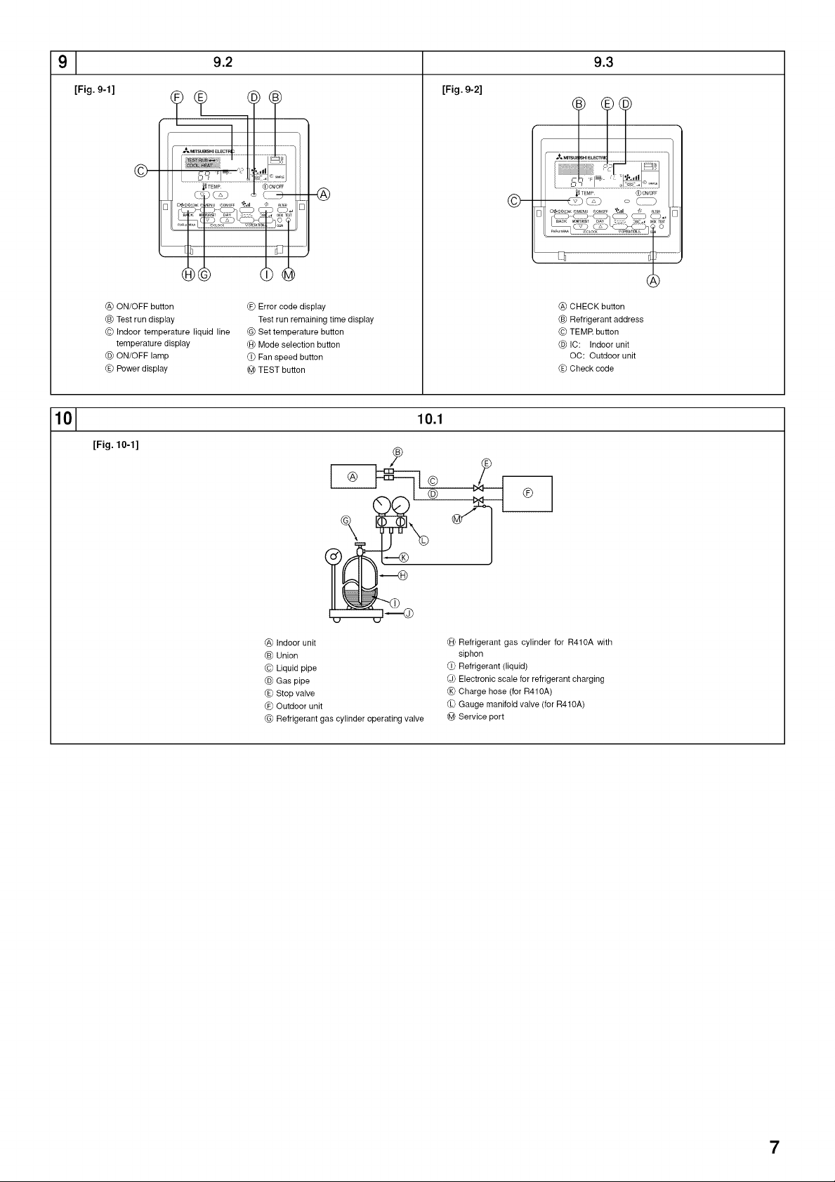
[Fig. 9-1] (P.7)
(_)ON/OFF button
C_Test rundisplay
(© Indoor temperature liquid line temperaturedisplay
(_)ON/OFF lamp
(_, Powerdisplay
@_Errorcode display
Test run remaining time display
G(_Set temperature button
(A_Modeselection button
(i_ Fanspeed button
@ TEST button
14
Page 15

9. Test run
9.3. Self-check
9.3.1. Wired remote controller
(_ Turn on the power.
(D Press the [CHECK] button twice.
(_ Set refrigerant address with [TEMP] button if system control is used.
(_ Press the [ON/OFF] button to stop the self-check.
• For description of
Q Check code
P1
P2, P9
E6, E7
P4
P5
PA
P6
EE
P8
E4
Fb
E0, E3
El, E2
E9
UP
U3, U4
UF
U2
U1, Ud
U5
U8
U6
U7
U9, UH
Others Other errors (Refer to the technical manual for the outdoor unit.)
On wired remote controller
(_) Check code displayed in the LCD.
each check code, refer to the following table.
Intake sensor error
Pipe (Liquid or 2-phase pipe) sensor error
Indoor/outdoor unit communication error
Drain sensor error
Drain pump error
Forced compressor error
Freezing/Overheating safeguard operation
Communication error between indoor and outdoor units
Pipe temperature error
Remote controller signal receiving error
Indoor unit control system error (memory error, etc.)
Remote controller transmission error
Remote controller control board error
Indoor/outdoor unit communication error (Transmitting error) (Outdoor unit)
Compressor overcurrent interruption
Open/short of outdoor unit thermistors
Compressor overcurrent interruption (When compressor locked)
Abnormal high discharging temperature/49C worked/insufficient refrigerant
Abnormal high pressure (63H worked)/Overheating safeguard operation For details, check the LED display
Abnormal temperature of heat sink of the outdoor controller board.
Outdoor unit fan safeguard stop
Compressor overcurrent interruption/Abnormal of power module
Abnormality of super heat due to low discharge temperature
Abnormality such as overvoltage or voltage shortage and abnormal synchronous signal to main circuit/
Current sensor error
Symptom Remark
[Fig. 9-2] (P.7)
_} CHECK button
Refrigerant address
© TEMR button
IC: Indoor unit
OC: Outdoor unit
(E_Check code
10. Maintenance
10.1. Gas charge
[Fig. 10-1] (P.7)
_A}Indoorunit
Union
© Liquidpipe
@ Gaspipe
(E_Stopvalve
@DOutdoor unit
(_ Refrigerant gas cylinder operatingvalve
(_ Refrigerant gas cylinder forR410A with siphon
(_) Refrigerant(liquid)
@ Electronic scalefor refrigerant charging
(_ Charge hose (for R410A)
(_ Gaugemanifold valve (for R410A)
@ Serviceport
1. Connect gas cylinder to the service port of stop valve (3-way).
2. Execute air purge of the pipe (or hose) coming from refrigerant gas cylinder.
3. Replenish specified amount of refrigerant, while running the air conditioner
for cooling.
Note:
In case of adding refrigerant, comply with the quantity specified for the refrigerating
cycle.
_, Caution:
• Do not discharge the refrigerant into the atmosphere.
Take care not to discharge refrigerant into the atmosphere during installa-
tion, reinstallation, or repairs to the refrigerant circuit.
• For additional charging, charge the refrigerant from liquid phase of the gas
cylinder.
If the refrigerant is charged from the gas phase, composition change may
occur in the refrigerant inside the cylinder and the outdoor unit. In this case,
ability of the refrigerating cycle decreases or normal operation can be impos-
sible. However, charging the liquid refrigerant all at once may cause the com-
pressor to be locked. Thus, charge the refrigerant slowly.
To maintain the high pressure of the gas cylinder, warm the gas cylinder with warm
water (under 104 °F [40 °C]) during cold season. But never use naked fire or steam.
15
Page 16

Index
1. Consignes de securite ........................................................................... 16
2. Choisir I'emplacement de Hnstallation ................................................... 16
3. Selection de I'emplacement d'installation et accessoires ...................... 17
4. Fixation des boulons de suspension ...................................................... 17
5. Installation de I'appareil ......................................................................... 18
6. Mise en place des tuyaux de r6frig6rant ................................................ 18
7. Travaux de conduites ............................................................................. 20
8. Installations electriques ......................................................................... 21
1. Consignes de securite
Avant la connexion au systeme, le signaler au distributeur d'electricite ou
demander son accord.
• Veuillez lire en entier "Les mesures de securite suivantes doivent toujours
6tre respectees" avant d'installer le climatiseur.
Comme ces mesures sont tres importantes pour votre securite, veuillez les
respecter.
• Les symboles signifient.
/_ Avertissement:
pourrait resulter en un deces, une blessure grave, etc.
Z_ Attention:
pourrait resulter en une blessure grave, selon les circonstances, si I'appareil
est incorrectement utilis&
Lorsque vous aurez lu le manuel en entier, veuillez le garder dans un en-
droit pratique, chez le client, avec le manuel d'utilisation.
/_ Avertissement:
• Ne pas installer I'appareil vous-m6me (client).
Toute mauvaise installation pourrait resulter en une blessure due a un incen-
die, un choc electrique, ou une fuite d'eau ou si I'appareil tombait. Consulter
votre distributeur ou technicien specialise.
• Vous assurer que I'appareil est installe dans un endroit assez solide pour en
supporter le poids.
Autrement, il pourrait tomber et par consequent blesser quelqu'un.
• Utiliser les c&bles specifies pour connecter les appareils interieur et exte-
rieur en toute securite, et attacher les fils fermement au bloc de sorties pour
qu'aucune force venant des fils ne soit exercee sur les bornes.
Toute connexion ou attachement defectueux pourrait resulter en un incen-
die.
• N'utilisez pas de rallonge et ne branchez pas plusieurs appareils a la m6me
prise de courant CA.
II y aurait risque d'incendie ou de decharge electrique a cause d'un contact
ou d'une isolation defectueux, ou a cause d'un exces de courant etc.
• Verifier que le gaz refrigerant ne fuit pas Iorsque I'installation est terminee.
• Veuillez suivre ce manuel durant I'installation.
Toute installation defectueuse pourrait 6tre la cause d'une blessure due a un
incendie, une decharge electrique, si I'appareil tombait ou une fuite d'eau.
Z_ Attention:
• Mettre I'appareil a la terre.
Ne pas relier le c_ble de terre au tuyau de gaz, d'eau, un parafoudre ou un
c&ble de terre telephonique. Toute mise a la terre defectueuse pourrait 6tre la
cause d'un choc electrique.
• Ne pas installer I'appareil dans un endroit o=3il sera expose a des gaz inflam-
mables.
Tout gaz accumule autour de I'appareil pourrait exploser.
• Installer un disjoncteur differentiel si necessaire (Iorsque I'endroit de I'instal-
lation est humide.)
Sans disjoncteur differentiel, il y aura risque de decharge electrique.
9. Marche d'essai ....................................................................................... 23
10. Entretien ................................................................................................ 24
Le manuel d'installation ne concerne que I'unite int@ieure et I'unit6 ext@ieure de
la s@ie SUZ.
Si I'appareil exterieur fait partie de la s@ie MXZ, consulter le manuel d'installa-
tion de cette s@ie MXZ.
Symboles sur rappareil
: Indique une action qui dolt _tre evitee.
O : Indique que des instructions importantes doivent _tre prises en consid@ation.
: Indique un element qui dolt _tre mis & la terre.
Z_ : Indique des precautions & prendre Iors du maniement de pieces tournantes.
_ : Indique que I'interrupteur principal dolt _tre desactive avant d'effectuer tout
travail d'entretien.
z_ : Danger d'electrocuition.
Z_: Attention, surface chaude.
Z_ Avertissement:
Prendre soin de lire les etiquettes se trouvant sur I'appareil principal.
• Veuillez suivre ce manuel durant I'installation electrique et veuillez utiliser un
circuit exclusif pour cette installation electrique.
Tout manque de capacite de circuit ou toute installation defectueuse pourrait
resulter en un incendie ou une decharge electrique.
• Veuillez fermement attacher les couvercles de la partie electrique de I'appa-
reil interieur et le panneau de service de I'appareil exterieur.
Tout attachement defectueux du couvercle de I'appareil interieur et/ou le pan-
neau de service de I'appareil exterieur pourrait resulter en un incendie ou un
choc electrique a cause de la poussiere, de I'eau, etc, pouvant s'infiltrer.
• Veuillez vous assurer d'utiliser la piece fournie ou les pieces specifiees pour
I'installation.
Toute piece defectueuse utilisee pourrait 6tre la cause d'un incendie, d'un
choc electrique, de I'appareil tombant de sa position, etc, ce qui resulterait
en une blessure ou une fuite d'eau.
• Aerez le local en cas de fuite de liquide frigorigene en cours de fonctionne-
ment.
Tout contact du liquide frigorigene avec une flamme libere des gaz toxiques.
• Veuillez suivre les instructions de ce manuel pour I'installation de la tuyaute-
rie et du systeme d'evacuation.
Si cette installation n'est pas faite correctement, il est possible que I'appareil
fuie et par consequent mouille ou abime vos meubles.
• Serrer I'ecrou evase avec une cle dynamometrique en respectant les indica-
tions du present manuel.
Un ecrou evase trop serre peut en effet casser apres un certain temps et
provoquer une fuite de refrigerant.
2. Choisir I'emplacement de I'installation
2.1. Appareil interieur
• Emplacement ne favorisant pas la circulation d'air.
• Emplacement favorisant une bonne repartition de I'air froid darts la piece.
• Emplacement ne favorisant pas une exposition directe au soleil.
• A une distance au moins egale b.1 m [39-3/8 in] d'un televiseur ou d'une radio
(pour eviter que I'image ne soit d_formee ou que des sons ne soient produits).
2.2. Appareil exterieur
• Emplacement ne favorisant pas une exposition aux rafales de vent.
• Emplacement favorisant une bonne circulation d'air sans poussiere.
• Emplacement ne favorisant pas une exposition directe & la pluie et au soleil.
• Emplacement ne suscitant pas une nuisance par le bruit de fonctionnement de
I'appareil et la pulsion d'air chaud pour le voisinage.
• Emplacement avec un mur solide ou un support ferme emp_chant la propagation
du bruit de fonctionnement et de vibrations.
16
• Emplacement permettant d'obtenir un eloignement suffisant d'une lampe fiuores-
cente ou de tout autre dispositif d'eclairage b.ampoule (la proximite de ces disposi-
tifs entravent la reception des signaux de commande du boitier de tel_commande
et emp_che le climatiseur de fonctionner normalement).
• Emplacement permettant de retirer facilement le filtre & air vers le bas.
,/_ Avertissement:
Fixer I'appareil interieur dans un plafond suffisamment resistant pour suppor-
ter son poids.
• Emplacement ot_ il n'y a aucun risque de fuites de gaz combustibles.
• Lorsque I'appareil est installe en hauteur, les pieds de support doivent _tre instal-
I_s.
• A 3 m [10 ft] au moins de I'antenne d'un t_leviseur ou d'une radio. (Autrement il
pourrait y avoir du brouillage sonore ou visuel.)
• Installer I'appareil & I'horizontale.
Page 17

2. Choisir I'emplacement de I'installation
Z_ Attention:
Les emplacements sousmentionnes doivent _tre evites pour effectuer rinstal-
lation s'il existe un risque de panne pour le climatiseur.
• Si rair a une teneur trop elevee en huile machine.
• Sites salins.
• Stations thermales.
• En presence de gaz sulfurique.
• Autres types de conditions climatiques speciales.
3. Selection de I'emplacement d'installation et accessoires
Choisir un endroit avec une surface suffisamment solide pour supporter le poids de
I'appareil.
Avant d'installer I'appareil, d_terminer la maniere de I'acheminer au lieu d'installa-
tion.
Choisir un endroit or) le bon fonctionnement de I'appareil ne peut pas _tre affect6
par un courant d'air.
Selectionner un endroit cO le debit d'alimentation en air et de retour d'air n'est pas
perturb&
Selectionner un endroit cO les tuyaux de refrig@ant peuvent facilement _tre instal-
les & I'ext@ieur.
Selectionner un emplacement qui permet de repartir I'air enti@ement dans toute la
piece.
Ne pas installer I'appareil dans un endroit sujet a des eclaboussures de graisse ou
de vapeur.
Ne pas installer I'appareil dans un endroit avec arriv6e de gaz combustible, entre-
p6t de gaz ou sujet a des fuites de gaz.
Ne pas installer I'appareil dans un endroit contenant des equipements qui produi-
sent des ondes de haute frequence (comme une machine b. souder fonctionnant
par ondes de haute fr6quence).
• Ne pas installer I'appareil dans un endroit cO le d_tecteur incendie est situe du c6te
de I'arrivee d'air. (Le detecteur d'incendie risque de se d6clencher par erreur suite
b.I'alimentation en air chaud pendant le fonctionnement du chauffage.)
• En cas de pr6sence de produits chimiques sur les lieux, comme dans des usines
chimiques ou des h6pitaux, une etude approfondie s'av@e necessaire avant de
proc6der a Hnstallation de I'appareil. (Certains produits chimiques peuvent en effet
endommager les composants plastiques du climatiseur.)
• Si I'appareil dolt fonctionner pendant Iongtemps quand Fair au-dessus du plafond
est a haute temp@ature/haute humidite (point de condensation sup@ieur & 79 °F
[26 °C]), la condensation d'humidite est possible dans I'appareil int@ieur. Couvrir la
totalite de la surface de I'unit6 int@ieure d'un mat@iau isolant (10-20 mm [13/32 b.
13/16 in]) de fagon a interdire la formation de condensation.
3.1. Fixer I'appareil interieur a un plafond suffisamment
resistant pour supporter son poids
[Fig. 3-1] (P.2)
@ Porte d'acces (_ Boftier des elements _lectriques
© Arriveed'air (_)Sortie d'air
(E_Surfacedu plafond _ Espace pour I'entretien (vue de c6t_)
(_ Espacepour I'entretien (vue du sens de la fl_che)
(_ 600 mm[23-5/8 in] ou plus (D 100 mm [3-15/16 in] ou plus
Q 10 mm [13/32 in] ou plus @ 300 mm[11-13/16 in] ou plus
/_ Avertissement:
L'appareil doit 6tre fermement installe sur une structure capable de supporter
son poids. Si le climatiseur est monte sur une structure trop fragile, il risque de
tomber et de blesser quelqu'un.
3.2. Prevoir I'espace necessaire pour I'installation et
rentretien
• Selectionner le meilleur sens pour I'arrivee d'air en fonction de la configuration de
la piece et du lieu d'installation.
• Pr6voir un espace suffisant pour le raccordement des c&bles et des tuyaux, ainsi
que pour I'entretien, sur les panneaux inf@ieur et lat6raux. Pour faciliter les travaux
de suspension et pour plus de s6curite, veuillez prevoir un maximum d'espace.
3.3. Appareil exterieur
Espace pour la ventilation et le service
Les appareils doivent _tre installes par un technicien qualifie suivant les regle-
mentations locales en vigueur.
Pour le raccordement des appareils ext@ieurs, reportez-vous au manuel d'instal-
lation fourni avec les appareils.
3.4. Elements qui accompagnent I'appareil interieur
I'appareil est livr6 avec les el6ments suivants:
No Nom Quantite
Q C0uvercledetuyau(pourlejointdestuyauxderefrigerant)petitdiametre120rnrn[3/4in] 1
Q C0uvercledetuyau(pourlejointdestuyauxder_frigerant)granddiametre120rnrn[3/4in] 1
Q Sangle 7
(_ Pieces de la tel_commande 1
@ C&ble de I'unit_ recevant le signal 1
@ Rondelle (pour la suspension) 8
Q Tuyau d'evacuation 1
Couvre-tube (pour tuyau d'evacuation) 60 mm [3/8 in] 1
@ Couvre-tube (pour tuyau d'evacuation) 30 mm [3/16 in] 1
@ Rondelle (pour le fil d'alimentation) 2
4. Fixation des boulons de suspension
4.1 Fixation des boulons de suspension
[Fig. 4-1] (P.2)
@ Centrede gravit_
Cadre de suspension
• Plafond: La structure du plafond varie d'un edifice b.un autre. Pour plus d'informa-
tions, veuillez prendre contact avec la societ_ de construction de I'immeuble.
Centre de gravite et poids du produit
Nom du modele
SEZ-KD09
SEZ-KD12
SEZ-KD15
SEZ-KD18
W (mm [in]) L (mm [in]) X (mm [in]) Y (mm [in]) Z (mm [in]) Poids du produit (kg [Ib])
625 [24-5/8] 752 [29-5/8] 263 [10-3/8] 351 [13-27/32] 106 [4-3/16] 19 [42]
625 [24-5/8] 952 [37-1/2] 286 [11-9/32] 448 [17-21/32] 104 [4-1/8] 22 [50]
625 [24-5/8] 952 [37-1/2] 280 [11-1/32] 437 [17-7/32] 104 [4-1/8] 24 [54]
625 [24-5/8] 1152 [45-3/8] 285 [11-1/4] 527 [20-3/4] 104 [4-1/8] 28 [62]
• Le cas echeant, renforcer les boulons de suspension pour assurer la protection en
cas de tremblement de terre.
* Utilisez M10 pour les boulons de suspension et les supports antisismiques
(fourni sur place).
(_) Renfort du plafond avec des elements supplementaires (poutres sur champ, etc)
n_cessaire pour maintenir le plafond a niveau et pour eviter qu'il vibre.
(_ Couper et retirer les elements de construction du plafond.
(_ Renforcer les elements de construction du plafond et ajouter d'autres elements
pour y fixer les planches du plafond.
17
Page 18

5. Installation de I'appareil
5.1. Suspension de I'appareil
Transporter I'appareil interieure jusqu'au site en la conservant dans son
emballage d'origine.
Pour le suspendre, utiliser une poulie de levage pour le soulever et le faire
passer par les boulons de suspension.
[Fig. 5-1] (P.2)
(_ Appareil
(_ Pouliede levage
[Fig. 5-2] (R2)
© Boulons (fourni sur place)
(_)Rondelles(accessoire)
([) Boulon desuspension M10 (fourni sur place)
6. Mise en place des tuyaux de refrigerant
6.1. Tuyaux de refrigerant
[Fig. 6-1] (P.3)
(a_Appareil interieur
@ Appareil exterieur
Reportez-vous au mode d'emploi de I'appareil ext@ieure pour les hauteurs limites
entre les appareils et pour la quantite de refrig@ant b. charger.
Eviter d'installer I'appareil dans les endroits suivants, pour eviter toute complication :
Eair contient trop d'huile provenant de machine ou de cuisson.
Dans un environnement sale, par exemple pres de lamer.
Pres de sources naturelles d'eau chaude.
Pres de gaz sulfurique.
Tout autre zone atmosph@ique inhabituelle.
Cet appareil a des connexions _vas_es sur les c6tes ext@ieurs et int@ieurs. (Fig. 6-1 )
Les tuyaux b.r6frig_rant sont utilis6s pour connecter les appareils int6rieur et exte-
rieur comme I'indique le croquis ci-dessous.
• Isoler entierement les tuyaux & refrig@ant et d'evacuation pour eviter toute con-
densation.
Pre,paration des tuyaux
• Des tuyaux de 3, 5, 7, 10 et 15 metres [5 ft] sont disponibles en option.
(1) Specifications des tuyaux disponibles dans le commerce.
Modele Tuyau Diametre ext@ieur Epaisseur Epaisseur Isolant
SEZ- A liquide 6,35 1/4 0.8mm[1/16in] 8mm[11/32in]
KD09 ,_,gaz 9,52 3/8 0.8mm[1/16in] 8mm[11/32in]
SEZ- Aliquide 6,35 1/4 0.Smrn[l/16in] 8mm[11/32in] Plastiquemousse
KD12 A gaz 9,52 3/8 0.8mm[1/16in] 8mm[11/32in] r6sistantala
SEZ- A liquide 6,35 1/4 0.Smrn[l/16in] 8mm[11/32in] chaleurgravit_
KD15 Agaz 12,7 1/2 0.Smrn[l/16in] 8mm[11/32in] ;p@ifiquede 0,045
SEZ- A liquide 6,35 1/4 0.Smrn[l/16in] 8mm[11/32in]
KD18 Agaz 12,7 5/8 1.0mrn[1/16in] 8mm[11/32in]
(2) Vous assurer que les deux tuyaux & r6frig@ant sont bien isol6s contre la conden-
sation.
(3) Le rayon du coude du tuyau b. r6frig@ant doit mesurer au moins 10 cm
[3-15/16 in].
Z_ Attention:
Utiliser risolant ayant repaisseur prescrite.Trop d'epaisseur emp6chera le stoc-
kage derriere rappareil interieur et un isolant trop mince ne pourra eviter le
suintage de condensation.
6.2. Evasement
• La cause principale de fuite de gaz est un evasement defectueux.
Veuillez effectuer I'evasement selon la methode suivante.
mm inch min.du mur del'isolant
5.2. Assurer I'emplacement de I'appareil et monter les
boulons de suspension
Utiliser le calibre livre avec le panneau pour verifier si I'appareil et les bou-
Ions de suspension sont places a rendroit indique. Si ce n'est pas le cas,
de la condensation peut se former en raison des courants d'air. Verifier
soigneusement les differents emplacements.
Utiliser un niveau pour verifier si la surface reperee 1_)est bien a niveau.
Veiller a ce que les ecrous des boulons de fixation soient bien serres avant
de fixer les boulons eux-m_mes.
Pour s'assurer d'une bonne vidange, suspendre soigneusement I'appareil
rhorizontale en se servant d'un niveau.
[Fig. 5-3] (P.2)
(_ Basde I'appareil int@ieur
/_ Attention:
Ne pas omettre de s'assurer que I'appareil est de niveau.
6.2.1. Couper le tuyau
[Fig. 6-3] (P.3)
(a_Tubes en cuivre
(_) Bonexemple
_ Mauvaisexemple
@ Penche
(e) Inegal
(_) Bavure
• Utiliser un coupe-tuyaux pour couper le tube en cuivre correctement.
6.2.2. Enlever les bavures
[Fig. 6-4] (P.3)
(a_Bavure
(_)Tuyau/tubeen cuivre
@ Al_soir suppl_mentaire
@ Coupe-tuyaux
• t_barber soigneusement la coupe de la section de tuyau/tube.
• Diriger vers le bas I'extr_mite de la section de tuyau/tube b.ebarber de mani@e que
les copeaux ne p_netrent pas dans le tuyau/tube.
6.2.3. Mettre I'ecrou en place
[Fig. 6-5] (P.3)
(a_)Ecrou _vas_
(6_Tube en cuivre
• Retirer les raccords coniques fixes sur les appareils int@ieure et exterieure et les
poser sur les tuyau/tube apres ebarbage.
(il est impossible de les fixer apres mise en forme conique)
6.2.4. Le fraisage
[Fig. 6-6] (P.3)
(a_Fraise
(_) Etau
_ Tubeen cuivre
d@Ecrou_vas_
(e_Serrage
• Effectuez I'evasement a I'aide de I'alesoir selon la m@hode suivante.
Dimensions
Diametre de tuyau
(mm [in]) B -+04[-1,'32](mm [in])
6,35 [1/4] 9,1 [3/8]
9,52 [3/8] 13,2 [17/32]
12,7 [1/2] 16,6 [21/32]
15,88 [5/8] 19,7 [25/32]
Coincer fermement le tube en cuivre dans un etau aux dimensions indiquees ci-
dessus.
L0rsdeI'utilisati0ndeI'0utilpourleR410A
A (ram [in])
Type d'embrayage
0 a 0,5 [0 b.1/32]
0 a 0,5 [0 b.1/32]
0 a 0,5 [0 b.1/32]
0 a 0,5 [0 b.1/32]
18
6.2.5. Verification
[Fig. 6-7] (P.3)
(a_Lisse (_ Rayuresur la surfaceevasee
(_) Eint@ieurbrille et n'est pas raye @ Craqu_
c_)Longueur egale @ Inegal
@ Trop (i_ Exemples de mauvais specimens
(._ Penche
• Si la section conique est defectueuse, la supprimer et r_peter les op@ations.
Page 19

6. Mise en place des tuyaux de refrigerant
6.3. Connexion des tuyaux
[Fig. 6-8] (P.3)
• Appliquer une fine couche d'huile de r6frig@ant sur la surface de conduite.
• Lors du raccordement, aligner le centre puis serrer le raccord conique de 3 b. 4
tours.
• Appliquer les couples de serrage sp6cifi_s dans letableau ci-dessous comme moyen
de r6f@ence pour les raccords de tuyauterie de I'appareil int@ieur et serrer avec
deux cles. Un serrage endommage la partie evas6e.
Diam. ext. Tuyau en cuivre
(mm [in])
e6,35 [1/4]
e9,52 [3/8]
el 2,7 [1/2]
e15,88 [5/8]
z_ Avertissement:
II faut veiller a ne pas retirer le raccord conique ! (La pression interne peut
provoquer leur echappement.)
Retirer recrou evase en procedant comme suit:
1. Desserrer I'ecrou jusqu'a ce qu'un sifflement se fasse entendre.
2. Ne jamais retirer I'ecrou tant que tout le gaz ne s'est pas echappe (c'est-a-
dire Iorsque le sifflement s'arr6te).
3. Verifier si tout le gaz s'est echappe avant de retirer I'ecrou.
Connexion de I'appareil exterieur
Connecter les tuyaux au raccord de vanne d'arr_t de I'appareil ext@ieur en proce-
dant comme pour I'appareil int@ieure.
• Pour le serrage, utiliser une cle dynamom@rique et serrer au m6me couple que
pour I'appareil int@ieure.
Isolation des tuyaux de refrigerant
• Apres le raccordement des tuyaux de r6frig_rant, isoler les joints (evas6s) avec
une gaine d'isolation thermique, comme illustr6 ci-dessous.
[Fig. 6-9] (P.3)
@ Couvre-tube (petitdiametre 120 mm [3/4 in]) (accessoire)
@ Precaution:
Extraire, sur le site, Hsolationthermique des tuyaux refrig@ants,introduirele raccord coni-
quepour rendre conique I'extremit_ et r_introduire Hsolation.
Veiller & ce qu'il n'y ait pas de formation de gouttes de condensation sur la tuyauterie en
cuivreexpos_e.
© Extr6mit_ du tuyaude r6frigerant liquide
@ Extr_mit_ dutuyau de r_frigerant gazeux
(E_Tuyauteriede refrigerant sur place _ Corps principal de I'appareil
(-@Couwe-tube(granddiarn_tre120mm[3/4in])(accessoite)(€1_Isolationthermique (fourni sur place)
(_) Tirer (,]_ Raccord conique
(_ Remettre & la position originale (0 S'assurer qu'il n'y a pas d'espaceici
@ Plaque sur la partie principale (_) Sangle (accessoire)
@ S'assurer qu'il n'y a pas d'espace ici. Diriger les raccordsvers le haut.
1.Retirer et jeter le bouchon de caoutchouc qui a et6 ins@6 & I'extr6mite de la tuyau-
terie de I'appareil.
2.Evaser I'extr6mit6 du tuyau de r6frig@ant.
3.Sur le site, extraire Hsolation thermique des tuyaux de r6frig@ant et replacer Hso-
lant comme b.I'origine.
Diam.ext. raccord conique Couple de serrage
(mm [in]) (N.m)
17 [11/16] 14- 18
22 [7/8] 34- 42
26 [1-1/32] 49- 61
29 [1-5/32] 68- 82
4,
La laisser ainsi pendant une ou deux minutes. Vous assurer que I'aiguille de la`]
soupape multiple de manometre reste sur la m_me position. Wrifier que le mano-|
metre indique bien -0,101 MPa (-760 mmHg). )
4,
*Ferme
*Ouvert
Cle hexagona e, *4 ou 5 tours
Robinet d'arr_t (-760 mmHg) (pour le R410A)
Port de service
-0,101 MPa Jauge de pression composee
/
Tuyau de
chargement
(pour le R410A)
Enlever rapidement la soupape multiple de manometre de la sortie de service de la]
soupape d'arr_t. J
"Lorsque
les
tuyaux b. refrigerant sont connectes et vid_s, ouvrir completement la1
soupape d'arr_t du o6te des tuyaux b.gaz et b.liquide. |
Une utilisation sans I'avoir enti@ement ouverte emp_chera I'appareil de fonction-|
ner du mieux possible et pourra causer des problemes. )
4, 4,
Longueur de tuyau: plus de 7 m [23 ft]
7 m [23 ft] maximum Ajouter la quantite de gaz
I ]I °n ue rdet u
Nul besoin d'ajouter de gaz.
(Serrer le capuchon de la sortie de service pour la remettre dans son etat d'origine.)
Adaptateur
anti-reflux
4,
4,
4,
Robinet d'arr_t
Jauge de pression
(pour le R410A)
Vanne des jauges
(pour le R410A)
Poignee pression
elevee (Hi)
Tuyau de chargement
(pour le R410A)
recommand&
(ou pompe & vide
equipee d'une
fonction anti-
reflux)
4,
( Resserrer le capuchon )
4,
( Test anti-fuites )
Precautions concernant le raccordement des tuyaux de refrigerant
Toujours utiliser des soudures non oxydantes afin qu'aucun corps etran-
ger ni aucune humidite ne penetre a rinterieur du tuyau.
Rev6tir le siege du goujon d'huile pour machine refrigerante et le serrer
fermement a I'aide de deux cles.
Placer une entretoise metallique pour soutenir les tuyaux de refrigerant de
telle sorte qu'aucune charge ne s'applique a la sortie des tuyaux de rappa-
reil interieur. Placer le support metallique a 50 cm [19-11/16 in] ou plus de la
connexion avec goujon de I'appareil interieur.
6.4. Test anti-fuites et methodes de vidange
METHODES DE VIDANGE "_
4,
Connecter les tuyaux & r_frig_rant (tuyaux b.liquide et b.gaz) entre les appareils_
mt@_eur et ext@_eur. J
du tuyau & gaz de I'appareil ext@ieur. (La soupape d'arr_t ne marchera pas
Enlever le capuchon de la sortie de service de la soupape d'arr_t situ6e sur le iC6rtse_l
qu'elle sera toute neuve (completement fermee et recouverte).)
Connecter la soupape multiple de gaz et la pompe a vide & la sortie de service de']
la soupape d'arr_t situee du c6te de I'appareil ext@ieur ot_se trouve le tuyau a gaz.J
4,
4,
Utiliser la pompe a vide.
(Vider pendant plus de 15 minutes.) J
Wrifier le vide avec la soupape multiple de manometre, puis fermer la soupape_
multiple de manometre, et arr_ter la pompe & vide. J
4,
4,
6.5. Travaux de mise en place du tuyau d'ecoulement
• S'assurer que le tuyau d'ecoulement soit place en pente vers le bas (pente de plus
de 1/100) vers le c6te ext@ieur (de la d_charge). Ne pas ajouter de piege.
• S'assurer que tout tuyau d'ecoulement de traverse a moins de 20 m [65 ft] (non
compris la diff@ence d'el_vation). Si le tuyau d'ecoulement est long, ajouter des
crochets metalliques pour le soutenir et eviter qu'il ne vibre.
Ne jamais pr_voir d'orifice de ventilation d'air par lequel I'ecoulement risquerait de
se repandre.
• Utiliser un tube en chlorure de vinyle dur D.E. e32 mm [1-1/4 in] comme conduite
d'ecoulement.
• Veiller ace que les tuyaux group,s soient 10 cm [3-15/16 in] en dessous de I'ouver-
ture d'_coulement situ_e sur le corps de I'appareil.
• Ne pas laisser de renfoncement pour les odeurs au port de d_charge de I'ecoule-
ment.
• Poser I'extremit_ du tuyau d'ecoulement de fagon b.ne pas gen@er d'odeurs.
• Ne jamais placer les tuyaux d'ecoulement dans un drainage gen@ant des gaz
ioniques.
[Fig. 6-10] (P.4)
O Tuyauteriecorrecte
X Tuyauterieerronee
@ Isolation(9 mm [3/8 in] minimum)
Pente descendante (1/100 minimum)
© Support metallique
(_ Purge d'air
(_ Lev_
@ Trappeanti-odeur
19
Page 20

6. Mise en place des tuyaux de refrigerant
Tuyaux group6s
(_)D.E.o 32mm [1-1/4 in]TUBE PVC
(_,Elargir leplus possible. 10 cm [3-15/16in] environ.-
@_Appareil int@ieur
G(_Elargir latuyauterie pour recevoir lestuyaux group,s.
(€1_Pente descendante (1/100 minimum)
(i_ D.E. o38 mm [1-1/2 in] TUBE PVC pour les tuyaux groupes. (Isolation de 9 mm [3/8 in]
minimum)
0_)Jusqu'& 550 mm [21-21/32 in]
Tuyaud'_coulement (accessoire)
_6)Surface horizontale ou legerementmontante
1. Inserer le tuyau d'6coulement (accessoire) dans I'ouverture d'ecoulement (marge
d'insertion : 25 mm [1 in]).
(Ne pas cintrer le tuyau au-del& de 45 ° pour eviter qu'il casse ou se bouche.)
(Rattacher le flexible au tuyau en chlorure de vinyle dur avec de la colle et le fixer
avec le ruban (accessoire).)
2. Fixer le tuyau d'ecoulement (D.E. e32 mm [1-1/4 in] TUBE PVC, fourni sur place).
(Rattacher le tuyau au tuyau en chlorure de vinyle dur avec de la colle et le fixer
avec le ruban (accessoire).)
3. Isoler le tuyau et la douille d'ecoulement (D.E. e32 mm [1-1/4 in] TUBE PVC)
(coude inclus).
4. Contr61er I'ecoulement. (Volt [Fig. 6-13])
5. Fixer le mat@iel d'isolation (accessoire), et le fixer avec la sangle (accessoire)
pour isoler I'ouverture d'ecoulement.
[Fig. 6-11 ] (P.4)
(_ Appareil int@ieur
(_ Couvre-tube (60mm [3/8 in]) (accessoire)
© Sangle (accessoire)
(_)Partievisible
(_,Marged'insertion
_ Tuyaud'_coulement (accessoire)
G(_Tuyaud'_coulement (D.E.032 mm [1-1/4 in]TUBE PVC,fourni sur place)
(€1_Mat@ield'isolation (fourni sur place)
(i_ Sangle (accessoire)
(.]_)180 + 5 mm[7-3/32 + 7/32 in] maxi.
(_ Absence de jeu.
Le raccordement du mat@ield'isolation dolt se joindre & la partie sup@ieure.
[Evacuation par gravite]
1. Ins@er le tuyau d'ecoulement (accessoire) dans I'ouverture d'ecoulement.
(Ne pas cintrer le tuyau au-dela de 45 ° pour eviter qu'il casse ou se bouche.)
La partie reliant I'unite int@ieure et le tuyau d'evacuation peut _tre debranchee
pour I'entretien. Fixer la partie avec le ruban fourni en accessoire, sans adhesif.
2. Fixer le tuyau d'ecoulement (D.E. e32TUBE PVC, fourni sur place).
(Rattacher le tuyau au tuyau en chlorure de vinyle dur avec de la colle et le fixer
avec le ruban (accessoire).)
3. Isoler le tuyau et la douille d'ecoulement (D.E. e32 TUBE PVC) (coude inclus).
[Fig. 6-12] (P.4) * Evacuation par gravite
(_ Appareil int@ieur
(_ Couvre-tube (30 mm [3/16 in]) (accessoire)
© Sangle (accessoire)
(_) Partie fixee avec du ruban
(_, Marge d'insertion
@_Tuyau d'_coulement (accessoire)
G(_Tuyau d'_coulement (D.E. o32 TUBE PVC, fourni sur place)
(€1_Mat@iel d'isolation (fourni sur place)
(i_ 145 + 5 mm maxi.
6.6. Confirmation des decharges d'ecoulement
Veiller a ce que le mecanisme de decharge d'ecoulement fonctionne nor-
malement et que les raccordements ne presentent aucune fuite.
• Le point ci-dessus dolt _tre respecte en mode de chauffage.
• Le point ci-dessus dolt _tre respecte avant de proceder aux travaux du plafond
dans le cas d'une construction neuve.
1. Retirer le couvercle de I'ouverture d'arrivee d'eau du c6te de la tuyauterie de I'ap-
pareil int@ieur.
2. Remplir la pompe d'alimentation en eau a I'aide d'un reservoir d'alimentation en
eau. Lors du remplissage, veiller a placer I'extr6mite de la pompe ou du r6servoir
dans un bac d'6coulement. (En cas d'insertion incomplete, de I'eau pourrait couler
sur I'appareil.)
3. Effectuer I'essai de fonctionnement en mode de refroidissement, ou placer le com-
mutateur SWE de la carte b.circuit imprime du boitier de commandes en position
de marche. (La pompe d'6coulement et le ventilateur doivent fonctionner sans
telecommande.) A I'aide d'un tuyau transparent, proceder a la d_charge du bac
d'ecoulement.
4. Apres confirmation, annuler le mode d'essai de fonctionnement, et couper I'ali-
mentation principale. Si le commutateur SWE est en position de marche, le placer
en position d'arr#t, et fixer le couvercle de I'ouverture d'arrivee d'eau dans sa
position d'origine. SWE SWE
[Fig. 6-13] (P.4)
(_ Ins@er I'extremit_ de la pompe de 2 & 4 cm [13/16 & 1-19/32 in].
(_ Retirer I'ouverture d'arriv_e d'eau.
© 2 000 litres environ
(_) Eau
(_, Ouverture de remplissage
_) Vis
[Fig. 6-14] (R4)
<Panneau int@ieur>
SWE SWE
I-J_l ---, l_J-I
ON OFF ON OFF
IJJq ---, l-F_q
ON OFF ON OFF
7. Travaux de conduites
• Utilisez le conduit en toile pour effectuer la connexion entre le corps principal et le
conduit.
• Utilisez des mat@iaux ininflammables.
/_ Attention:
Le bruit du tuyau d'admission augmentera fortement si radmission @ est
attachee directement sous le corps principal. II est donc imperatif d'instal-
ler I'admission @ le plus loin possible du corps principal.
Faire particulierement attention Iors de son installation pour une admis-
sion par le bas.
Utilisez suffisamment d'isolation thermique afin d'eviter toute condensa-
tion sur les conduits de sortie et leurs brides.
Raccordez le corps principal du climatiseur et le conduit afin que leurs
potentiels correspondent.
La distance entre la grille d'aspiration et le ventilateur doit 6tre superieure
850 mm [33-15/32 in].
Si la distance est inferieure a 850 mm [33-15/32 in], installez un filet de
securite pour eviter tout contact avec le ventilateur.
[Fig.7-1 ] (P.5)
_) Entree d'air
(_ Sortie d'air
(© Panneau d'acces
(_) Surface du plafond
(_, Conduit en toile
@_ Filtre & air
G(_Grille d'aspiration
20
Page 21

8. Installations electriques
8.1. Alimentation electrique
Sp6cification electrique Capacit6 de disjoncteur (A)
Alimentation electrique SEZ-KD09 SEZ-KD12 SEZ-KD15 SEZ-KD18
(1 phase _/N, 208/230V, 60Hz) 10 10 20 20
z_ Avertissement:
• Le compresseur ne fonctionne pas si la connexion de la phase d'alimenta-
tion electrique est incorrecte.
• Une protection de mise a la terre avec disjoncteur sans fusible (disjoncteur
de perte a la terre) est gen6ralement installee pour (_).
• Le c_blage de connexion entre les appareils interieurs et exterieur peut 6tre
rallonge jusqu'a un maximum de 50 m [164 ft], et la rallonge totale y compris
le c_blage en pont entre les pieces sera de 80 m [262 ft] maximum.
Utiliser des contacteurs presentant une distance entre contacts au moins egale
3 mm [1/6 in] pour chaque pble.
* Etiquetter chaque interrupteur selon sa fonction (chauffage, unite, etc.).
[Fig. 8-1] (P.5)
@ Appariel interieur
Appareil exterieur
© Tel_commande filiaire
@ Interrupteur principal/fusible
(E_ Mise & la terre
8.2. Branchement des fils interieurs
Procedure
1. Enlevez les 2 vis pour d6tacher le couvercle de la boke des composants electri-
ques.
2. Faites passer chaque c&ble par le point d'entree des c&bles et introduisez-les
dans la boke des composants electriques. (Procurez-vous le c&ble d'alimentation
et le c&ble de connexion entre les unites ext@ieure et int@ieure Iocalement et
utilisez la tel6commande fournie avec I'unit&)
3. Raccorder solidement les c&bles d'alimentation, de raccordement entree-sortie et
de la telecommande aux blocs de raccordement.
4. Fixez les c&bles & I'aide de crampons a I'int@ieur de la boTte des composants
electriques.
5. Remettez le couvercle du bottler des composants electriques a sa place d'origine.
• Attachez le c&ble d'alimentation en courant et le c&ble des unites interieure/exte-
rieure b.la boTte de commande en vous servant d'une douille tampon comme force
de tension. (connexion PG ou similaire).
Avertissement:
• Veuiller remettre proprement le couvercle de la partie electrique. Autrement,
il y aura risque d'incendie, ou de choc electrique a cause de la poussiere, de
reau etc. pouvant s'infiltrer.
• Utiliser le cable prescrit de liaison d'appareils interieure/exterieure pour re-
lier les appareils interieure et exterieure. Fixer soigneusement le c_ble au
bornier de maniere qu'aucune contrainte ne soit appliquee sur les bornes de
raccordement. Une mauvaise connexion et une mauvaise installation electri-
que pourraient 6tre la cause d'incendie.
[Fig. 8-2-1] (P.5)
@ Cache-vis (2 pcs)
(B_Cache
[Fig. 8-2-2] (RS)
@ Boftierde bornier
Orificed'6jection
© Retirer
[Fig. 8-2-3] (P.5)
@ Utilisez leconduit pourque lec&ble,du faitde son poids,et uneforce externe nefasse pas
pression sur le connecteur dela borne d'alimentation.
C&blede connexionde I'appareil int@ieur/ext@ieur
© Conduit
@ Bornier
(E_Ouverture(pourc&blede connexion de I'appareil int@ieur/ext@ieur)
@_Rondelle (accessoire)
(_ Force detension
(_ Utiliser une bagueordinaire
C&blede la tel_commande
[Fig. 8-2-4] (P.5)
@ Bloc terminal pour la connexion de I'appareil int@ieur/ext@ieur
Boftierde raccordement de la t_lecommande
© C&blede connexion de I'appareil int@ieur/ext@ieur
@ C&bledela tel_commande
• Effectuez le c&blage selon le diagramme en bas et b.gauche. (Veuillez vous procu-
rer le c&ble Iocalement).
Assurez-vous que les c&bles utilis6s sont de la polarite correcte.
[Fig. 8-3] (P.6)
@ Bornier int6rieur
® Filde mise a la terre (vert/jaune)
© C&ble de connection pour appareil int@ieur/exterieur 3 conducteurs, 1,5 mm 2 [AWG 16] ou
plus
@ Bornier exterieur
(E_Cordon d'alimentation electrique
(_ C&ble de connection pour appareil int@ieur/exterieur 3 conducteurs, 1,5 mm _ [AWG 16] ou
plus, conforme & la prescription 245 IEC 57.
(_ Embase de borne int@ieur
@ Embase de borne ext@ieur
@ Posez toujours un c&ble de raise & la terre (1 noyau de 1,5 mm_ [AWG 16]) plus long que les
autres c&bles.
(_ C&ble de la tel_commande
No. × taille de fil (mm _) :C&ble 2C × 0,3
Conducteur accessoire de la t_lecommande
(Iongueur du c&ble : 10 m [32 ft], non polaire, max. 500 m [1640 ft])
Tel_commande filaire
Cordon d'alimentation
• Branchez les blocs de sorties comme I'indique le diagramme ci-dessous.
Z_ Attention:
• Effectuer les travaux d'electricite comme il convient.
• Serrer fermement les vis des bornes pour les emp6cher de se desserrer.
• Puis tirer legerement sur les fils pour vous assurer qu'ils ne bougent pas.
8.3. Telecommande
8.3.1. Pour la telecommande filaire
1) Methodes d'installation
(1) Selectionner I'endroit d'installation de la telecommande.
Les detecteurs de temp6rature se trouvent sur la telecommande et I'appareil inte-
rieur.
Fournir les pieces suivantes Iocalement:
Boke de commutation pour deux pieces
Tuyau de conduit en cuivre fin
Contre-6crous et manchons
[Fig. 8-4] (P.6)
@ T616commande
Degagements requispour la tel_commande
© Emplacement de I'installation
(2) Sceller I'entree de service du cordon de la tel_commande avec du mastic pour
eviter toute invasion possible de rosee, d'eau, de cafards ou de vers.
[Fig. 8-5] (P.6)
(.&,_Pour Hnstallationdans labofte decommutation:
(B_Pour uneinstallation directe aumur,choisir unedes methodessuivantes:
• Faire un trou dans le mur pour passer lecordonde la t_lecommande (afin de faire passer le
cordon de la t_lecommande par derriere), puis sceller letrou avecdu mastic.
• Faire passer le cordonde latel6commande &travers lapartiesup@ieurecoupee, puisscel-
ler I'encoche avecdu mastic de lam6me fagon que ci-dessus.
© Mur G(_ Bofte de commutation
@ Conduit (€1_Cordon de la tel6commande
(E_Contre-ecrou (i_ Sceller avec du mastic
(#_Manchon (,]_ Vis en bois
B-1. Pour faire passer le cordon de la telecommande derriere la telecommande:
B-2. Pour faire passer le cordon de la telecomamnde a travers la partie supe-
rieure:
(3) Pour Hnstaller directement au mur
2) Methodes de connnexion
Connecter le cordon de la telecommande au bornier.
[Fig. 8-6] (P.6)
@ Au bloc de raccordement de I'appareilint@ieur
(B_TB6 (Pas de polarite)
(_ Regler le commutateur N° 1 montre ci-dessous si deux telecommandes sont uti-
lisees pour le m6me groupe.
3) Selection des fonctions
Si deux telecommandes sont connectees, r6glez I'une sur "principal" et I'autre sur
"auxiliaire". Pour prendre connaissance des proc6dures de configuration, consultez
"Selection des fonctions" dans le mode d'emploi de I'appareil int@ieur.
21
Page 22

8. Installations electriques
8.4. Reglage des fonctions (Selection des fonctions par
la telecommande)
Se reporter au mode d'emploi fourni avec la tel6commande pour les r6glages et la
fagon d'op@er.
8.4.1 Reglage des fonctions sur rappareil (Selection des fonctions
de rappareil)
1) Changement du reglage de pression statique exterieure [Fig. 8-7] (P.6)
• Veillez a changer le r6glage de la pression statique ext@ieure selon le conduit et la
grille utilises.
® Passer au mode de reglage des fonctions.
Eteindre la tel6commande.
Appuyer simultan6ment sur les touches @ et (_) et les maintenir enfon-
cees pendant au moins 2 secondes. FUNCTION commencera b.clignoter.
@ Utiliser la touche © pour r6gler I'adresse du r6frig@ant (HI) sur 00.
Q Appuyer sur @ ;[--] se met a clignoter sur I'affichage du num@o d'appareil (IV).
(_ Utiliser le bouton © pour specifier le num@o d'appareil (N) & 01-04 ou AL.
@ Appuyer sur la touche (_) (MODE) pour sp6cifier I'adresse du refrig@ant/numero
d'appareil ; [--] clignote momentan6ment sur I'affichage du num@o de mode ( I ).
@ Appuyez sur la touche (_ pour r6gler le num@o de mode ( I ) sur 08.
Q Appuyer sur la touche _), le num@o de programmation actuellement selectionne
( ]:1) clignotera.
Utilisez la touche (_ pour changer le num@o de reglage en fonction de la pres-
sion statique ext@ieure qui sera utilis6e.
Pression statique No. de r6glage du No. de r6glage du
ext@ieure mode No. 08 mode No. 10
5 Pa (0,02 in WG) 1 2
15 Pa (0,06 in WG) (en usine) 1 1
35 Pa (0,14 in WG) 2 1
50 Pa (0,20 in WG) 3 1
®
Appuyer sur la touche MODE (_, les num@os de programmation et de mode ( I )
et ( [[ )changeront et seront continuellement affich_s, et les details de la program-
mation pourront _tre confirmes.
®
Appuyer simultan6ment sur les touches FILTER @ et TEST RUN (_) pendant au
moins 2 secondes. IZecran de s61ection des fonctions apparatt momentan6ment,
et I'affichage d'arr_t du climatiseur apparak.
®
Pour r6gler la pression statique sur SPa (0.02 in.WG), rep6ter les op@ations ®
@. (Regler le num@o de mode sur 10 pour I'etape @.)
Autres fonctions
2)
®
Selectionner le num@o d'appareil 00 pour les r6glages. (Reglages pour tousles
appareils int@ieurs)
Se reporter au tableau des fonctions 1.
®
Selectionner les num@os de r6glage 01 a 04 ou AL pour ces r6glages. (Reglages
pour chaque appareil int@ieur)
Pour specifier I'appareil int@ieur dans un systeme individuel, selectionner le nu-
m@o d'appareil 01.
Pour sp6cifier chaque appareil int@ieur parmi deux, trois ou quatre appareils inte-
rieurs raccord6s, Iorsque ces appareils fonctionnent ensemble, selectionner un
num@o d'appareil 01 a 04.
Pour specifier tousles appareils int@ieurs parmi deux, trois ou quatre appareils
interieurs raccordes Iorsque ces appareils fonctionnent ensemble, selection-
ner AL.
Se reporter au tableau des fonctions 2.
Tableau des fonctions 1
Selectionner I'appareil num@o 00
Mode
Restauration automatique apres une coupure de courant "1
(FONCTION DE REMISE EN MARCHE AUTOMATIQUE)
D6tection de la temp@ature int@ieure
Connectivite LOSSNAY
Tableau des fonctions 2
Selectionner les appareils num@o 01 a 04 ou tousles appareils (AL [t_lecommande avec fil]/07 [tel_commande sans ill])
Mode Parametre
Signe du filtre 100 Hr
Pression statique ext@ieure 15 Pa (0,06 in WG)
"1 Une fois I'alimentation retablie, le climatiseur redemarreapres 3 minutes.
Rernarque : Si la fonction d'un appareil interieur a et_ chang_e en s_lectionnant un autre fonction apres I'installation, toujours indiquer le contenu en saisissant un O ou une autre marque dans la
case & cocher appropriee des tableaux.
Parametre
Non disponible
Disponible "1
Moyenne de fonctionnement de I'appareil interieur
Regl6e par la tel_commande de I'appareil int_rieur
D_tecteur interne de la tel_commande
Non supportee
Supportee(l'appareilinterieurn'estpas equiped'une prised'air ext@ieure)
Supportee(l'appareilinterieurestequiped'uneprise d'air ext@ieure)
2500 Hr
Pas d'indicateur de signe du filtre
35 Pa (0,14 in WG)
50 Pa (0,20 in WG)
Identique au r_glage du mode No. 08
5 Pa (0,02 in WG) (regler le No. de mode 08 sur 1)
No. de Mode No.dereglage Reglageinitial
01
02 2
03 2
No. de Mode No.dereglage
07 2
08 2
10
1
2 O
1 O
3
1 O
3
Reglageinitial Cocher
1
3
1
3
1
2
O
O
O
Cocher
22
Page 23

9. Marche d'essai
9.1. Avant la marche d'essai
b Lorsque rinstallation, le tuyautage et le c_blage des appareils interieur et
exterieur sont termines, verifier rabsence de fuites de refrigerant, la fixation
des c&bles d'alimentation et de commande, I'absence d'erreur de polarite et
contr_ler qu'aucune phase de ralimentation n'est deconnectee.
b Utiliser un megohm-metre de 500 V pour s'assurer que la resistance entre
les terminaux d'alimentation electrique et la terre soit au moins de 1,0 MQ.
b Ne pas effectuer ce test sur les terminaux des c&bles de contr_le (circuit
basse tension).
Z_ Avertissement:
Ne pas utiliser le climatiseur si la resistance de risolation est inferieure
1,0 MQ.
Resistance de risolation
Apres I'installation ou apres la coupure prolongee de la source d'alimentation, la
resistance de Hsolation chutera en de£& d'l M_ en raison de I'accumulation de r6fri-
g@ant dans le compresseur. IIne s'agit pas d'un dysfonctionnement. Respectez les
procedures suivantes.
1. Retirer les c&bles du compresseur et mesurer la resistance de Hsolation du com-
presseur.
2. Si la resistance de Hsolation est inferieure b. 1 M_, le compresseur est d_faillant
ou du r6frig_rant s'est accumul6 dans le compresseur.
3. Apres avoir connecte les c&bles au compresseur, celui-ci commence & chauffer
des qu'il est sous tension. Apres avoir mis sous tension le compresseur pendant
les durees indiqu6es ci-dessous, mesurer de nouveau la r6sistance de Hsolation.
• La r6sistance de I'isolation chute en raison de I'accumulation de refrig@ant
dans le compresseur. La r6sistance depassera 1 M_Qapres que le compres-
seur a chauff6 pendant deux ou trois heures.
(Le temps mis par le compresseur pour chauffer varie selon les conditions
atmosph@iques et I'accumulation de r6frig_rant).
• Pour faire fonctionner le compresseur dans lequel s'est accumul6 du refrig6-
rant, il est necessaire de le faire chauffer pendant au moins 12 heures afin
d'eviter toute d_faillance.
4. Si la r6sistance de Hsolation d6passe 1 M_, le compresseur n'est pas d6fec-
tueux.
Z_ Attention:
• Le compresseur fonctionnera uniquement si les connexions des phases de
ralimentation electrique sont correctes.
• Mettez I'appareil sous tension au moins 12 heures avant de le faire fonction-
her.
- La mise en marche de I'appareil immediatement apres sa mise sous tension pour-
rait provoquer de s@ieux d_g&ts aux elements internes. Ne mettez pas I'appareil
hors tension pendant la saison de fonctionnement.
9.2. Marche d'essai
9.2.1. Utilisation de la telecommande filaire
(_ Mettre I'appareil sous tension au moins 12 heures avant I'essai de fonctionne-
ment.
(_) Appuyer deux fois sur la touche [TEST] (ESSAI). -_ Affichage a cristaux liquides
"TEST RUN" (ESSAI DE FONCTIONNEMENT)
(_ Appuyer sur la touche [Mode selection] (Selection Mode). -_ Wrifier si la soufflerie
fonctionne.
(_ Appuyer sur la touche [Mode selection] (Selection Mode) et passer en mode re-
froidissement (ou chauffage). -_ Wrifier si la soufflerie souffle de Fair froid (ou
chaud).
(_) Appuyer sur la touche [Fan speed] (Vitesse soufflerie). -_ Wrifier si la vitesse de la
soufflerie change.
(_) Wrifier le bon fonctionnement du ventilateur de I'appareil ext@ieur.
(_ Arr_ter I'essai de fonctionnement en appuyant sur la touche [ON/OFF] (Marche/Arr_t).
-_ Arr_t
(_) Enregistrez un num@o de telephone.
Le num@o de telephone de I'atelier de reparation, de I'agence commerciale, etc.,
& contacter en cas de panne peut _tre enregistr_ dans la telecommande. Le nu-
mero de telephone s'affichera en cas d'erreur. Pour prendre connaissance des
procedures d'enregistrement, consultez le mode d'emploi de I'appareil int_rieur.
[Fig. 9-1] (P.7)
@ ToucheON/OFF
Affichage de la marched'essai
© Affichage de la temperature int@ieurede la conduite de liquide
@ Temoin ON/OFF
(E_Affichage demise sous tension
(F_Affichage du code d'erreur
Affichage du temps restant pour la marched'essai
(_ Touchede r_glagede la temp@ature
(_ Touchedes_lection des modes
(_ Touchede r_glagede la vitesse de ventilation
@ ToucheTEST
23
Page 24

9. Marche d'essai
9.3. Auto-verification
9.3.1. Pour la telecommande filaire
Q Mettre sous tension.
Q Appuyer deux fois sur la touche [CHECK] (v6rification).
Q Regler I'adresse du r6frig6rant & I'aide de la touche [TEMP] Iors de I'utilisation de
la tel6commande du systeme.
(_ Appuyer sur la touche [ON/OFF] (marche/arr_t) pour arr_ter I'auto-verification.
Pour une description d6taill6e de chacun des codes de v6rification, consulter le tableau suivant.
(_) Code de
verification Sympt6me Remarque
P1 Erreur du capteur d'admission
P2, P9 Erreur du capteur sur tuyaux (Tuyau liquide ou & 2 phases)
E6, E7 Erreur de communication de I'appareil interieur/exterieur
P4 Erreur du capteur d'ecoulement
P5 Erreur de la pompe d'ecoulement
PA Erreur du compresseur & circulation forc6e
P6 Fonctionnement du dispositif de protection en cas de gel/surchauffe
EE Erreur de communication entre les appareils interieur et exterieur
P8 Erreur de temp6rature des tuyaux
E4 Erreur de reception du signal de la tel6commande
Fb Erreur du systeme de contr61e de I'appareil interieur (erreur de memoire, etc.)
E0, E3 Erreur de transmission de la tel6commande
E1, E2 Erreur du panneau du contr61eur de la tel6commande
E9 Erreur de communication de I'appareil interieur/exterieur (Erreur de transmission) (Appareil exterieur)
UP Interruption due b.la surintensite du compresseur
U3, U4 Circuit ouvert/court-circuit des thermistances de I'appareil exterieur
UF Interruption due b.la surintensite du compresseur (Quand compresseur verrouille)
U2 Temperature de d6charge anormalement elev6e/fonctionnement de 49C/refrig6rant insuffisant
U1, Ud Pression anormalement elev6e (Fonctionnement de 63H)/Fonctionnement du dispositif de protection en cas de surchauffe Pour de plus amples informations,
U5 Temperature anormale de la source de froid contr61ez I'ecran LED du panneau
U8 Arr_t du dispositif de protection du ventilateur de I'appareil exterieur du contr61eur exterieur.
U6 Interruption due & la surintensite du compresseur/Module d'alimentation anormal
U7 Surchauffe anormale due b.une temp6rature de d_charge basse
U9, UH Anomalies telles que surtension ou sous-tension et signal synchronise anormal vers le circuit principal/
Erreur du capteur d'intensite
Autres Autres erreurs (Consultez le manuel technique de I'appareil exterieur.)
Sur la tel6commande sans fil
(_) Code de verification affich6 & I'ecran LCD.
[Fig. 9-2] (P.7)
Touche CHECK (verification)
(_ Adresse du refrigerant
_© Touche TEMP.
IC: Appareil interieur
OC: Appareil exterieur
(_ Code de v_rification
10.Entretien
10.1. Charge de Gaz
[Fig. 10-1] (P.7)
Appareil interieur
(_ Raccord
_©Conduitede liquide
Conduit de gaz refrigerant
(9 Robinetd'arr_t
_ Appareilexterieur
G(_Vannede fonctionnement du cylindre de refrigerant
(€1_Cylindrede gaz refrigerant pour R410A, avecsiphon
(i_ R_frigerant (liquide)
(3_Echelle electroniquepour la charge de refrigerant
Conduiteflexible de chargement(pour le R410A)
(9 Jauge collectrice (pour le R410A)
@ Prise de service
1. Raccorder le tuyau de gaz au port de service de la vanne d'arr_t (a 3 voles).
2. Purger rair du tuyau raccorde au tuyau de gaz refrigerant.
3. Ajouter la quantite specifiee de refrigerant, pendant que le climatiseur fonc-
tionne en mode rafraichissement.
Remarque:
En cas d'ajout de refrigerant, respecter la quantite pr_cis_e pour le cycle de refrige-
ration.
Attention:
• Ne pas decharger le refrigerant dans ratmosphere.
Faire attention de ne pas decharger le refrigerant dans ratmosphere durant
rinstallation, une nouvelle installation ou la reparation du circuit refrigerant.
• En cas de supplement de charge, charger le refrigerant sous sa forme liquide
partir d'un cylindre de gaz.
Si le refrigerant est charge sous sa forme gazeuse, sa composition risque de
se modifier a rinterieur du cylindre et dans rappareil exterieur. Dans ce cas,
la capacite de refroidissement du refrigerant diminue ou le fonctionnement
normal peut m_me s'averer impossible. Attention: une charge trop rapide de
tout le refrigerant liquide risque de bloquer le compresseur; des Iors, nous
conseillons de charger le refrigerant lentement.
Pour maintenir une pression elev_e dans le cylindre de gaz, le rechauffer avec de
I'eau chaude (d'une temperature inferieure b.104 °F [40 °C]) pendant la saison froide.
Ne jamais utiliser une flamme vive ou de la vapeur pour effectuer cette operation.
24
Page 25

This product is designed and intended for use in the residential,
commercial and light-industrial environment.
Please be sure to put the contact address/telephone number on
this manual before handing it to the customer.
KB79K740H02
Art=MITSUBISHI ELECTRIC CORPORATION
HEAD OFFICE: TOKYO BLDG. 2-7-3 MARUNOUCHI. CHIYODA-KU. TOKYO 100-8310 JAPAN
 Loading...