

Mitsubishi Electronics SEZ-KD09NA4.TH, SEZ-KD12NA4.TH, SEZ-KD15NA4.TH, SEZ-KD18NA4.TH User Manual
Page 1

M-SERIES SINGLE ZONE SYSTEMS
SEZ DUCTED HEAT PUMP SYSTEMS
1. INDOOR UNITS .........................................................................................................................................................SEZ-3
2. OUTDOOR UNITS .....................................................................................................................................................SEZ-4
3. SYSTEM .....................................................................................................................................................................SEZ-5
3-1. SPECIFICATIONS ..................................................................................................................................................SEZ-6
SEZ-KD09NA4 SEZ-KD12NA4 ...............................................................................................................................SEZ-6
SEZ-KD15NA4 SEZ-KD18NA4 ...............................................................................................................................SEZ-7
SUZ-KA09NA SUZ-KA12NA SUZ-KA15NA .........................................................................................................SEZ-8
SUZ-KA09NA SUZ-KA12NA SUZ-KA15NA .........................................................................................................SEZ-9
SUZ-KA09NA SUZ-KA12NA SUZ-KA15NA .......................................................................................................SEZ-10
Efciency Ratings ................................................................................................................................................... SEZ-11
3-2. EXTERNAL DIMENSIONS....................................................................................................................................SEZ-12
SEZ-KD09NA4 .......................................................................................................................................................SEZ-12
SEZ-KD12NA4 .......................................................................................................................................................SEZ-12
SEZ-KD15NA4 .......................................................................................................................................................SEZ-12
SEZ-KD18NA4 .......................................................................................................................................................SEZ-12
SUZ-KA09NA.TH SUZ-KA12NA.TH SUZ-KA15NA.TH ...................................................................................SEZ-13
SUZ-KA18NA.TH ...................................................................................................................................................SEZ-14
3-3. CENTER OF GRAVITY ......................................................................................................................................... SEZ-15
3-4. ELECTRICAL WIRING DIAGRAMS......................................................................................................................SEZ-16
SEZ-KD09NA4.TH SEZ-KD12NA4.TH SEZ-KD15NA4.TH SEZ-KD18NA4.TH ...........................................SEZ-16
SUZ-KA09NA.TH SUZ-KA12NA.TH ...................................................................................................................SEZ-17
SUZ-KA15NA.TH ...................................................................................................................................................SEZ-18
SUZ-KA18NA.TH ...................................................................................................................................................SEZ-19
3-5. REFRIGERANT SYSTEM DIAGRAMS ................................................................................................................SEZ-20
SEZ-KD09NA4.TH SEZ-KD12NA4.TH SEZ-KD15NA4.TH SEZ.KD18NA4.TH............................................SEZ-20
SUZ-KA12NA.TH SUZ-KA15NA.TH ...................................................................................................................SEZ-21
3-6. CAPACITY CORRECTION CURVE BY TEMPERATURE ....................................................................................SEZ-22
(1) Cooling Performance Curve..............................................................................................................................SEZ-22
(2) Heating Performance Curve .............................................................................................................................SEZ-23
3-7. CAPACITY CORRECTION TABLE BY TEMPERATURE ......................................................................................SEZ-25
(1) Cooling Capacity ...............................................................................................................................................SEZ-25
(2) Heating Capacity ..............................................................................................................................................SEZ-26
(3) M-Series Cooling Correction .............................................................................................................................SEZ-27
(4) M-Series Defrost Correction .............................................................................................................................SEZ-27
(5) M-Series Heating Correction.............................................................................................................................SEZ-28
Due to continuing improvement, above specication may be subject to change without notice.
SEZ Ducted Heat Pump Systems (August 2014)
© 2014 Mitsubishi Electric US, Inc.
SEZ-1
Page 2

M-SERIES SINGLE ZONE SYSTEMS
3-8. CAPACITY CORRECTION CURVE BY REFRIGERANT PIPING LENGTH.........................................................SEZ-29
3-9. CAPACITY CORRECTION TABLE BY REFRIGERANT PIPING LENGTH .......................................................... SEZ-30
(1) Cooling capacity correction ...............................................................................................................................SEZ-30
(2) Maximum refrigerant piping length & maximum height difference ....................................................................SEZ-30
(3) M-Series Piping Correction Cooling ..................................................................................................................SEZ-31
(4) M-Series Piping Correction Heating..................................................................................................................SEZ-31
3-10. CHARGE CALCULATIONS ................................................................................................................................SEZ-32
(1). Addition Of Refrigerant.....................................................................................................................................SEZ-32
3-11. AIR FLOW DATA .................................................................................................................................................SEZ-33
(1) Indoor Unit ........................................................................................................................................................SEZ-33
3-12. SOUND PRESSURE LEVELS ............................................................................................................................SEZ-37
(1) Indoor Unit ........................................................................................................................................................SEZ-37
(2) Outdoor Unit......................................................................................................................................................SEZ-41
3-13. STANDARD OPERATION RANGE .....................................................................................................................SEZ-42
3-14. ACCESSORIES ..................................................................................................................................................SEZ-43
(1) Indoor Unit ........................................................................................................................................................SEZ-43
(2) Outdoor Unit......................................................................................................................................................SEZ-46
Due to continuing improvement, above specication may be subject to change without notice.
SEZ-2
SEZ Ducted Heat Pump Systems (August 2014)
© 2014 Mitsubishi Electric US, Inc.
Page 3

1. INDOOR UNITS
• SEZ-KD09NA4.TH
• SEZ-KD12NA4.TH
• SEZ-KD15NA4.TH
• SEZ-KD18NA4.TH
Due to continuing improvement, above specication may be subject to change without notice.
SEZ Ducted Heat Pump Systems (August 2014)
© 2014 Mitsubishi Electric US, Inc.
SEZ-3
Page 4

2. OUTDOOR UNITS
• SUZ-KA09NA.TH
• SUZ-KA12NA.TH
• SUZ-KA15NA.TH
• SUZ-KA18NA.TH
Due to continuing improvement, above specication may be subject to change without notice.
SEZ-4
SEZ Ducted Heat Pump Systems (August 2014)
© 2014 Mitsubishi Electric US, Inc.
Page 5

3. SYSTEM
• Horizontal-ducted indoor unit for concealed applications
• Ultra thin body: 7-7/8” high
• Built-in drain mechanism for condensate removal; lifts to 21-11/16”
• Quiet operation - as low as 23 dB(A)
• Choice of fan speeds: Low, Medium, and High; Auto fan speed control also included
• Indoor unit powered from outdoor unit using A-control
• Self-check function -- onboard diagnostics
• Advanced microprocessor control
• Auto restart following a power outage
• Hand-held Wireless Remote Controller
• Anti-allergy Enzyme Filter
• Limited warranty: ve years parts and seven years compressor
Due to continuing improvement, above specication may be subject to change without notice.
SEZ Ducted Heat Pump Systems (August 2014)
© 2014 Mitsubishi Electric US, Inc.
SEZ-5
Page 6
3-1. SPECIFICATIONS
SEZ-KD09NA4 SEZ-KD12NA4
0.05
0.46
13600
Heating
63 to 83 (17 to 28)
208/230V (60Hz)
SEZ-KD12NA4
0.07
0.57
11500
Cooling
67 to 86 (19 to 30)
0.04
0.39
10900
Heating
63 to 83 (17 to 28)
208/230V (60Hz)
SEZ-KD09NA4
0.06
0.51
8100
Cooling
67 to 86 (19 to 30)
-
0.096
Galvanized
7.0-9.0-11.0
116-150-183
Direct-driven
Sirocco fan x 2
247-317-388
DC brushless motor
0.02-0.06-0.14-0.20 (5-15-35-50)
-
0.096
5.5-7.0-9.0
Galvanized
91-116-150
Direct-driven
Sirocco fan x 2
194-247-317
DC brushless motor
0.02-0.06-0.14-0.20 (5-15-35-50)
50
15
1/8 (1.6)
200 x 990 x 700
7-7/8 x 39 x 27-9/16
ø1/4 (ø6.35) Flare
42
15
ø3/8 (ø9.52) Flare
1/8 (1.6)
200 x 790 x 700
ø1/4 (ø6.35) Flare
ø3/8 (ø9.52) Flare
7-7/8 x 31-1/8 x 27-9/16
10
23-28-33
O.D. 1-9/32 (32)
PP Honeycomb fabric (washable)
ERZV10D471
Fuse (250V 6.3A)
Installation Manual, Instruction Book
Cross fin (Aluminum fin and copper tube)
Polystyrene foam, Polyethylene foam, Urethane foam
To outdoor unit : 3P To wired remote controller : 2P
-
Drain hose (flexible joint), Wired Remote Controller
10
23-26-30
O.D. 1-9/32 (32)
PP Honeycomb fabric (washable)
ERZV10D471
Fuse (250V 6.3A)
Installation Manual, Instruction Book
Cross fin (Aluminum fin and copper tube)
Polystyrene foam, Polyethylene foam, Urethane foam
To outdoor unit : 3P To wired remote controller : 2P
Drain hose (flexible joint), Wired Remote Controller
BTU/h
kW
Power input
Capacity
Model Name
Power source
A
°F(°C)
in.WG(Pa)
Type x Quantity
External static press
Current
Airflow direction
Temperature set range Remote controller
Fan
3
kW
m
CFM
L/S
Driving mechanism
Blower motor output
Blower type
Airflow rate(Low-Mid-High)
Airflow rate(Low-Mid-High)
Airflow rate(Low-Mid-High)
External finish
mm
In.
External dimension
H x W x D
in.(mm)
in.(mm)
in.(mm)
Lbs.
in.(mm)
A
R410A
Liquid
Amperage of wire breaker
Min.size of wire
Net weight
Refrigerant
Wiring
dB<A>
R410A
Gas
Drain piping diameter
piping diameter
Sound level (Low-Mid-High)
Insulation material
Air filter
Refrigerant control device
(measured in anechoic room)
Protection devices
Heat exchanger
/min
Due to continuing improvement, above specication may be subject to change without notice.
SEZ-6
SEZ Ducted Heat Pump Systems (August 2014)
A
Varistor
Terminal block
Power outlet
Document
Accessory
Standard
attachment
Remark
© 2014 Mitsubishi Electric US, Inc.
<Cooling> Indoor:80°FD.B. / 67°FW.B. (26.7°CD.B. / 19.4°CW.B.) Outdoor:95°FD.B. (35°CD.B.)
1.Cooling/Heating capacity indicates the maximum value at operation under the following condition.
Note
Pipe length:24-9/16ft (7.5m) Height difference:0ft (0m)
Heating capacity value at 1:1system
2.Power consumption. Run current at 0.06[in.WG] (15Pa) (external static pressure)
3.Cooling capacity value at 1:1system
<Heating> Indoor:70°FD.B. (21.1°CD.B.) Outdoor:47°FD.B. / 43°FW.B. (8.3°CD.B. / 6.1°CW.B.)
Page 7
3-1. SPECIFICATIONS
SEZ-KD15NA4 SEZ-KD18NA4
0.07
0.63
20100
Heating
63 to 83 (17 to 28)
208/230V (60Hz)
SEZ-KD18NA4
0.09
0.74
17200
Cooling
67 to 86 (19 to 30)
0.07
0.63
18000
Heating
63 to 83 (17 to 28)
208/230V (60Hz)
SEZ-KD15NA4
0.09
0.74
14100
Cooling
67 to 86 (19 to 30)
-
0.096
Sirocco fan x 4
Direct-driven
Galvanized
423-529-635
12.0-15.0-18.0
DC brushless motor
0.02-0.06-0.14-0.20 (5-15-35-50)
200-250-300
-
0.096
Sirocco fan x 3
Direct-driven
Galvanized
353-441-529
167-208-250
10.0-12.5-15.0
DC brushless motor
0.02-0.06-0.14-0.20 (5-15-35-50)
62
15
1/8 (1.6)
200 x 1190 x 700
O.D. 1-9/32 (32)
ø1/4 (ø6.35) Flare
ø1/2 (ø12.7) Flare
7-7/8 x 46-7/8 x 27-9/16
54
15
1/8 (1.6)
200 x 990 x 700
7-7/8 x 39 x 27-9/16
O.D. 1-9/32 (32)
ø1/4 (ø6.35) Flare
ø1/2 (ø12.7) Flare
20
30-34-38
ERZV10D471
Fuse (250V 6.3A)
PP Honeycomb fabric (washable)
Installation Manual, Instruction Book
Cross fin (Aluminum fin and copper tube)
Polystyrene foam, Polyethylene foam, Urethane foam
To outdoor unit : 3P To wired remote controller : 2P
-
Drain hose (flexible joint), Wired Remote Controller
20
30-34-37
ERZV10D471
Fuse (250V 6.3A)
PP Honeycomb fabric (washable)
Installation Manual, Instruction Book
Cross fin (Aluminum fin and copper tube)
Polystyrene foam, Polyethylene foam, Urethane foam
To outdoor unit : 3P To wired remote controller : 2P
Drain hose (flexible joint), Wired Remote Controller
BTU/h
kW
Power input
Capacity
Model Name
Power source
A
°F(°C)
Current
Airflow direction
Temperature set range Remote controller
kW
in.WG(Pa)
Type x Quantity
External static press
Blower motor output
Blower type
Fan
L/S
m
Driving mechanism
Airflow rate(Low-Mid-High)
mm
Airflow rate(Low-Mid-High)
Airflow rate(Low-Mid-High)
External dimension
External finish
In.
H x W x D
in.(mm)
in.(mm)
in.(mm)
Lbs.
in.(mm)
A
R410A
Liquid
Min.size of wire
Amperage of wire breaker
Net weight
Refrigerant
Wiring
dB<A>
R410A
Gas
piping diameter
Drain piping diameter
Sound level (Low-Mid-High)
Insulation material
Air filter
Refrigerant control device
Protection devices
(measured in anechoic room)
Varistor
Heat exchanger
/min
3
CFM
Due to continuing improvement, above specication may be subject to change without notice.
SEZ Ducted Heat Pump Systems (August 2014)
© 2014 Mitsubishi Electric US, Inc.
A
Document
Standard
Terminal block
Power outlet
Accessory
attachment
1.Cooling/Heating capacity indicates the maximum value at operation under the following condition.
Note
Remark
Pipe length:24-9/16ft (7.5m) Height difference:0ft (0m)
Heating capacity value at 1:1system
<Cooling> Indoor:80°FD.B. / 67°FW.B. (26.7°CD.B. / 19.4°CW.B.) Outdoor:95°FD.B. (35°CD.B.)
3.Cooling capacity value at 1:1system
2.Power consumption. Run current at 0.06[in.WG] (15Pa) (external static pressure)
<Heating> Indoor:70°FD.B. (21.1°CD.B.) Outdoor:47°FD.B. / 43°FW.B. (8.3°CD.B. / 6.1°CW.B.)
SEZ-7
Page 8
NOTES : *1.Rating conditions (cooling)-Indoor : D.B. 26.7°C(80°F), W.B. 19.4°C(67°F) Outdoor : D.B. 35°C(95°F), W.B. 23.9°C(75°F)
*2.Rating conditions(heating)-Indoor : D.B. 21.1°C(70°F), W.B. 15.6°C(60°F) Outdoor : D.B. -8.3°C(17°F), W.B. -9.4°C(15°F)
3-1. SPECIFICATIONS
SUZ-KA09NA SUZ-KA12NA SUZ-KA15NA
SUZ-KA09NA.TH SUZ-KA12NA.TH SUZ-KA15NA.TH SUZ-KA18NA.TH
Indoor unit SEZ-KD09NA4.TH SEZ-KD12NA4.TH SEZ-KD15NA4.TH SEZ-KD18NA4.TH
Outdoor unit
Max. Capacity Btu/h 10,900 13,300 17,000 19,000
Rated Capacity Btu/h 8,100 11,500 14,100 17,200
Model name
Cooling
Min. Capacity Btu/h 3,800 3,800 3,800 3,800
Total input W 670 920 1,170 1,380
EER Btu/h 12 12.5 12 12.5
SEER Btu/h 15 16 15.5 17.5
Moisture Removal Pints/h 1.5 2.4 2.6 3.4
SHF 0.80 0.76 0.80 0.79
Max. Capacity Btu/h 14,100 16,400 21,100 24,900
Rated Capacity Btu/h 10,900 13,600 18,000 21,600
Heating
Min. Capacity Btu/h 4,800 4,800 4,800 4,800
Total input W 1,020 1,140 1,500 1,700
COP W/W 3.13 3.50 3.52 3.72
HSPF(IV) Btu/h/W 10.0 10.0 10.0 10.0
Max. Capacity Btu/h 6,700 9,000 11,900 12,100
Heating
at low ambient
Total input W 1,000 1,180 1,650 1,830
COP W/W 2.14 2.43 2.43 2.40
Phase,Cycle,Voltage 1phase, 60Hz, 208/230V
Breaker size A 15
Indoor - Outdoor S1-S2 AC208 / 230V
Indoor - Outdoor S2-S3 DC 12 - 24V
Power supply
Voltage
(heating)-Indoor : D.B. 21.1°C(70°F), W.B. 15.6°C(60°F) Outdoor : D.B. 8.3°C(47°F), W.B. 6.1°C(43°F)
Due to continuing improvement, above specication may be subject to change without notice.
SEZ-8
SEZ Ducted Heat Pump Systems (August 2014)
© 2014 Mitsubishi Electric US, Inc.
Page 9
NOTES : *1.Rating conditions (cooling)-Indoor : D.B. 26.7°C(80°F), W.B. 19.4°C(67°F) Outdoor : D.B. 35°C(95°F), W.B. 23.9°C(75°F)
*2.Rating conditions(heating)-Indoor : D.B. 21.1°C(70°F), W.B. 15.6°C(60°F) Outdoor : D.B. -8.3°C(17°F), W.B. -9.4°C(15°F)
3-1. SPECIFICATIONS
SUZ-KA09NA SUZ-KA12NA SUZ-KA15NA
Optional parts
SUZ-KA09NA.TH SUZ-KA12NA.TH SUZ-KA15NA.TH SUZ-KA18NA.TH
Indoor unit SEZ-KD09NA4.TH SEZ-KD12NA4.TH SEZ-KD15NA4.TH SEZ-KD18NA4.TH
Outdoor unit
MCA A 1
MOCP A 15
Model name
Indoor unit
Blower Motor F.L.A 0.51 0.57 0.74
CMM 5.5 - 7 - 9 7 - 9 - 11 10 - 12.5 - 15 12 - 15 - 18
Blower Motor Output W 96
Air ow DRY
(Lo-Mid-Hi) WET
CFM 194 - 247 - 317 247 - 317 - 388 353 - 441 - 529 423 - 529 - 635
CMM 4.9 - 6 - 8 6 - 8 - 10 9 - 11.2 - 14 11 - 14 - 17
CFM 174 - 222 - 285 222 - 285 - 349 317 - 396 - 476 381 - 476 - 572
Air ow DRY
(Lo-Mid-Hi) WET
23 - 26 - 30 23 - 28 - 33 30 - 34 - 37 30 - 34 - 38
kg 19 22 24 28
dB (A)
D:mm [inch] 700 [27-9/16]
W:mm [inch] 790 [31-1/8] 990 [39] 1190 [46-7/8]
External pressure in.WG [Pa] 0.02 / 0.06 / 0.14 / 0.20 [5/15/35/50]
Sound level (Lo-Mi-Hi)
Dimension
H:mm [inch] 200 [7-7/8]
Unit
lbs 42 50 54 62
mm [inch] 32 [1-1/4]
Weight
Unit
Field Drain pipe O.D.
Remote Controller
(heating)-Indoor : D.B. 21.1°C(70°F), W.B. 15.6°C(60°F) Outdoor : D.B. 8.3°C(47°F), W.B. 6.1°C(43°F)
Due to continuing improvement, above specication may be subject to change without notice.
© 2014 Mitsubishi Electric US, Inc.
SEZ Ducted Heat Pump Systems (August 2014)
SEZ-9
Page 10
NOTES : *1.Rating conditions (cooling)-Indoor : D.B. 26.7°C(80°F), W.B. 19.4°C(67°F) Outdoor : D.B. 35°C(95°F), W.B. 23.9°C(75°F)
*2.Rating conditions(heating)-Indoor : D.B. 21.1°C(70°F), W.B. 15.6°C(60°F) Outdoor : D.B. -8.3°C(17°F), W.B. -9.4°C(15°F)
3-1. SPECIFICATIONS
SUZ-KA09NA SUZ-KA12NA SUZ-KA15NA
Flared
Not Supplied
SUZ-KA09NA.TH SUZ-KA12NA.TH SUZ-KA15NA.TH SUZ-KA18NA.TH
Indoor unit SEZ-KD09NA4.TH SEZ-KD12NA4.TH SEZ-KD15NA4.TH SEZ-KD18NA4.TH
Outdoor unit
MCA A 12 14
MOCP A 15
Blower Motor F.L.A. 0.50 0.93
Model name
Outdoor unit
R.L.A. 6.6 7.4 10
Blower Motor Output W 55 77
Compressor KNB073FQDHC KNB092FQAHC SNB130FQBH
CFM 1,151 / 1,225 1,229 / 1,172 1,243 / 1,229 1,730 / 1,659
CMM 32.6 / 34.7 34.8 / 33.2 35.2 / 34.8 49 / 47
L.R.A. 8.2 9.3 12.5
Air ow
(Cooling/Heating)
Refrigerant Control Linear Expansion Valve
Defrost Method Reverse Cycle
Sound level at cooling dB (A) 46 49 49 54
Sound level at heating dB (A) 50 51 51 56
W:mm [inch] 800 [31-1/2] 840 [33-1/16]
External nish Ivory Munsell 3Y 7.8/1.1
Dimension
30 [66] 35 [77] 36 [80] 54 [119]
kg [lbs]
D:mm [inch] 285 [11-1/4] 330 [13]
H:mm [inch] 550 [21-5/8] 850 [33-7/16]
Weignt
Charge, R410 A kg [lbs,oz] 0.9 [1 lb 16 oz] 1.15 [2 lb 9 oz] 1.80 [3 lb 16 oz]
Oil L [oz] 0.32 (NEO 22) [10.8] 0.45 (NEO 22) [15.2]
Gas side O.D. mm [inch] 9.52 [3/8] 12.7 [1/2]
Liquid side O.D. mm [inch] 6.35 [1/4]
Refrigerant
Refrigerant pipe size
Height difference Max. 40 ft Max. 50 ft
Length Max. 65 ft Max. 100 ft]
Refrigerant pipe length
Refrigerant Piping
Connection Method
(heating)-Indoor : D.B. 21.1°C(70°F), W.B. 15.6°C(60°F) Outdoor : D.B. 8.3°C(47°F), W.B. 6.1°C(43°F)
Due to continuing improvement, above specication may be subject to change without notice.
SEZ-10
SEZ Ducted Heat Pump Systems (August 2014)
© 2014 Mitsubishi Electric US, Inc.
Page 11
3-1. SPECIFICATIONS
Efciency Ratings
Outdoor Unit Indoor Unit SEER EER HSPF
COP
@ 47° F
COP
@ 17° F
SEZ DUCTED HEAT PUMP SYSTEMS
SUZ-KA09NA SEZ-KD09NA4 21.00 13.6 10 4.20 2.76
SUZ-KA12NA SEZ-KD12NA4 20.25 12.5 10 3.60 2.86
SUZ-KA15NA SEZ-KD15NA4 21.00 13.0 10 3.30 2.88
SUZ-KA18NA SEZ-KD18NA4 19.20 10.5 10 3.32 2.70
Note:
Efciency values based on AHRI 210/240 test method.
Energy
Star
Yes
Yes Yes
Yes
Yes Yes
Tax
Credit
Due to continuing improvement, above specication may be subject to change without notice.
SEZ Ducted Heat Pump Systems (August 2014)
© 2014 Mitsubishi Electric US, Inc.
SEZ-11
Page 12
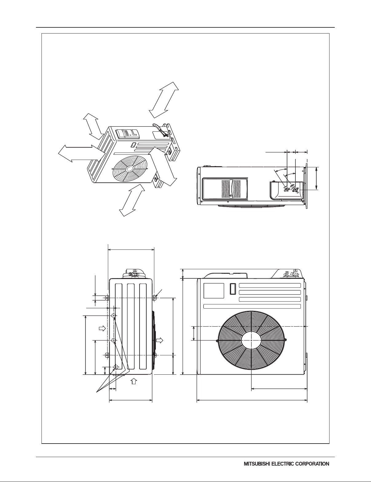
3-2. EXTERNAL DIMENSIONS
(46-7/8)
1190
(39)
990
(31-1/8)
790
N
(48-25/32)
1239
(40-29/32)
1039
(33-1/16)
839
M
Drain pipe(O.D.ø32(1-1/4))
Terminal block (Remote controller transmission line)
Terminal block (Indoor/outdoor connecting line)
2
Refrigerant piping
flare connection (liquid)
ø12.7(1/2)
mm(in.)
(35-7/16)
(27-9/16)
(19-11/16)
(41-3/4)
(33-7/8)
(26)
(47-1/4)
(39-3/8)
(31-1/2)
(39-3/8)
(31-1/2)
(23-5/8)
(41-3/4)
(33-7/8)
(26)
(47-3/16)
(39-5/16)
(31-7/16)
(45-3/8)
(37-1/2)
(29-5/8)
(43-5/16)
(35-7/16)
(27-9/16)
700
Drain pipe(O.D.ø32(1-1/4))
(Emergency draining)
ø6.35(1/4)
ø9.52(3/8)
SEZ-KD15NA4
900 952 998 860
9
800 1000 860
7
700
20
24
16
L
900
500
K
9
5
J
1060
660
H
800600
7
660798752
K nocko ut h ole ø27( 1-3/32 )
(Remote controller transmission line)
K nocko ut h ole ø27 (1-3/3 2)
(Indoor/outdoor connecting line)
G
1200
F
1000
E
11
D
1060
C
1100B1152
SEZ-KD09NA4
SEZ-KD12NA4
SEZ-KD18NA4
Model A
1198
Gas pipe Liquid pipe
L-ø2.9(1/8)
2×2-ø2.9(1/8)
2×E-ø2.9(1/8)
Control box
Air filter
Suspension bolt hole
4-14×30(9/16×1-3/16) Slot
Refrigerant piping
flare connection (gas)
1
1
2
Drain pipe(O.D.ø32(1-1/4))
(Spontaneous draining)
Air
inlet
Air
outlet
N
M
175±5(6-29/32±7/32)
Less than 300
Less than 550
(11-13/16)
(21-21/32)
More than 20
More than 10
57(2-1/4)
57(2-1/4)
(1-31/32 ~ 5-29/32)
(30-19/32)
(17-23/32)
(11-13/16)
(17-23/32)
More than 300
(13/16)
(13/32)
(3-9/16)
(5-29/32)
(2-25/32)(4-19/32)
70
10(13/32)
(3-15/16)
(1-15/16) (24-5/8)
450
37(1-15/32)
200(7-7/8)
H
157.5(6-7/32)20(13/16)
100(3-15/16)
37(1-15/32)
12(1/2)
12(1/2)
88(3-15/32)
100(3-15/16)XJ=K
100(3-15/16)
88(3-15/32)
777
50(1-31/32)
50 ~ 150
50(1-31/32)
G
450
10(13/32)
49
25(1)
170(6-23/32)
102(4-1/32)
116
100 25(1)
23(29/32)
C
B (Suspension bolt pitch)23(29/32)
A
90
D (Duct)
100(3-15/16)X(E-1)=F
100(3-15/16)
15(19/32)
Drain hose (I.D.ø32(1-1/4))
<accessory>
(Actual length)
Note2
Access door
Required space for service and maintenance
Access door
Ceiling surface
Make the access door at the appointed position properly
for service maintenance.
Note1. Use M10 screw for the suspension bolt (field supply).
2. Keep the service space for the maintenance at the bottom.
3. This chart indicates for SEZ-KD15NA4 model, which has 3 fans.
SEZ-KD09,12NA4 models have 2 fans.
SEZ-KD18NA4 model has 4 fans.
4. When an inlet duct is used, remove the air filter (supply with the unit), then install the filter (field supply) at suction side.
159(6-9/32)
345(13-19/32)
20(13/16)
30(1-3/16)
23(29/32)
270(10-21/32)
20(13/16)
625(Suspension bolt pitch)
700(27-9/16)
677(26-21/32)
150(Duct)
SEZ-KD09NA4
SEZ-KD12NA4
SEZ-KD15NA4
SEZ-KD18NA4
Unit: mm (inch)
Due to continuing improvement, above specication may be subject to change without notice.
SEZ-12
SEZ Ducted Heat Pump Systems (August 2014)
© 2014 Mitsubishi Electric US, Inc.
Page 13
3-2. EXTERNAL DIMENSIONS
Liquid pipe :1/4 (flared)
Gas pipe :3/8 (flared) (KA09/12)
1/2 (flared) (KA15)
6-23/32
2
5-7/8
2-23/32
1-3/4
15-3/4
12 ~ 12-3/4
13-9/16
11/16
1-9/16
7/8
21-5/8
11-1/32
13/32
31-1/2
19-11/16
5-15/16
11-29/32
17/3229/32 11-1/4
Air in
handle
Air in
Air out
2- 3/8 13/16 Oval hole
Drain hole 1-5/8
REQUIRED SPACE
Basically open 4 inch or more
without any obstruction in front
and on both sides of the unit.
14 in. or more
8 in. or more
4 in. or more
4 in. or more
Open two sides of left,
right, or rear side.
SUZ-KA09NA.TH SUZ-KA12NA.TH SUZ-KA15NA.TH
Unit: mm (inch)
Due to continuing improvement, above specication may be subject to change without notice.
© 2014 Mitsubishi Electric US, Inc.
SEZ Ducted Heat Pump Systems (August 2014)
SEZ-13
Page 14
3-2. EXTERNAL DIMENSIONS
20-9/32
14-3/16
Air in
11-25/32
2-19/32
Air in
Air out
19-11/16
33-1/16
13
2
4-25/32
33-7/16
16-15/16
3-3/16
4-3/8
×
13/16 slot
1-11/32
1-9/16
Drain 3 holes
(ø1
-5/16)
30°
35°
2-9/16
Liquid:1/4(flared)
Gas :1/2(flared)
3-9/16
8-11/32
6-21/32
Open as a rule
20 inch or more if
the front and both
sides are open
4 inch or more/
8 inch or more if
there are obstacles
to both sides
Open as a rule
20 inch or more if the back,
both sides and top are open
REQUIRED SPACE
14 in. or more
4 in. or more
Unit: Inch
SUZ-KA18NA.TH
Due to continuing improvement, above specication may be subject to change without notice.
SEZ-14
SEZ Ducted Heat Pump Systems (August 2014)
© 2014 Mitsubishi Electric US, Inc.
Page 15

3-3. CENTER OF GRAVITY
YX
LW
Z
c
C
A
a b
B
SEZ-KD09NA4.TH SEZ-KD12NA4.TH SEZ-KD15NA4.TH SEZ-KD18NA4.TH
Unit: inch(mm)
Model name W L X Y Z
SEZ-KD09NA.TH
SEZ-KD12NA.TH
SEZ-KD15NA.TH
SEZ-KD18NA.TH
24-5/8
(625)
24-5/8
(625)
24-5/8
(625)
24-5/8
(625)
SUZ-KA09NA.TH SUZ-KA12NA.TH SUZ-KA15NA.TH
29-5/8
(752)
37-1/2
(952)
37-1/2
(952)
45-3/8
(1152)
10-3/8
(263)
11-9/32
(286)
11-1/32
(280)
11-1/4
(285)
13-27/32
(351)
17-21/32
(448)
17-7/32
(437)
20-3/4
(527)
4-3/16
(106)
4-1/8
(104)
4-1/8
(104)
4-1/8
(104)
Unit: inch(mm)
Model name A B C a b c
SUZ-KA09NA.TH
SUZ-KA12NA.TH
SUZ-KA15NA.TH
SUZ-KA18NA.TH
Due to continuing improvement, above specication may be subject to change without notice.
© 2014 Mitsubishi Electric US, Inc.
11-1/16
(280)
11-13/16
(300)
5-9/16
(140)
5-7/8
(150)
SEZ Ducted Heat Pump Systems (August 2014)
9-1/2
(240)
13-3/8
(340)
31-1/2
(800)
33-1/16
(840)
11-1/4
(285)
13
(330)
21-5/8
(550)
33-7/16
(850)
SEZ-15
Page 16

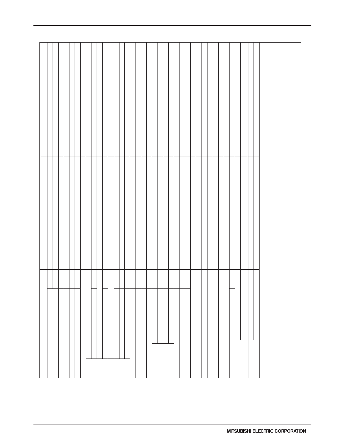
3-4. ELECTRICAL WIRING DIAGRAMS
4
WIRING DIAGRAM
SEZ-KD09NA4.TH
SEZ-KD12NA4.TH
SEZ-KD15NA4.TH
SEZ-KD18NA4.TH
12
1~
M
ON
OFF
SW6
DC294-340V
RECTIFY CIRCUIT
RU
SW1
BZ1
SW2
LED1
CN1
W.B.
RFI
R.B.
1
2
X1
FUSE
DRAINPUMP
135
(BLACK)
CN01
CNP
INSIDE SECTION OF CONTROL BOX
(BLUE)
CN22
31
1
LED1
CN3C
SW2SW1
CN32
CN30(GREEN)
(RED)
CN20
CN41
SWE
ON
OFF
CN51
(BLUE)
1474
59
95
2
12
41
FS TH2 TH5 TH1
FAN MOTOR
TB15
1
2
(RED)
CN105
(RED)
CN4F
(WHITE)
CN90
(WHITE)
CN44
(WHITE)
CNMF
(WHITE)
12
CN2L
TB6
(BLUE)
LED3
3
LED2
I. B.
S1
TB4
S3
S2
1
1
1
19
TRANSMISSION
WIRES DC 12V
-
+
MS
3~
SW2
SWITCH (HEATING ON/OFF)
SWITCH (COOLING ON/OFF)
SW1
RECEIVING UNIT
RU
LED (RUN INDICATOR)
LED1
BUZZER
BZ1
IR WIRELESS REMOTE CONTROLLER BOARD
COND./EVA. TEMP. THERMISTOR
TH5
PIPE TEMP. THERMISTOR/LIQUID
TH2
INTAKE AIR TEMP. THERMISTOR
TH1
CONNECTOR (EMERGENCY OPERATION)
SWITCH (FOR CAPACITY CODE)
SWITCH (FOR MODE SELECTION)
SWITCH (FOR MODEL SELECTION)
SWE
CONNECTOR (REMOTE SWITCH)
CONNECTOR (LLC)
CONNECTOR (LOSSNAY)
CONNECTOR (BACK-UP HEATING)
NAME NAMESYMBOL SYMBOLSYMBOL
I.B. I.B.
W.B.
OPTIONAL PARTS
R.B.
CN32
CN30
INDOOR CONTROLLER BOARD INDOOR CONTROLLER BOARD
SW2
SW1
SW6
SYMBOL EXPLANATION
NAME
CN2L
CN24
CONNECTOR (HA TERMINAL-A)
CN51
CN90
CN105
CN41
CONNECTOR (CENTRALLY CONTROL)
CONNECTOR (WIRELESS)
CONNECTOR
(RADIO FREQUENCY INTERFACE)
FUSE AC250V 6.3A
FUSE
X1
AUX. RELAY
TB15
FLOAT SWITCH
RADIO FREQUENCY INTERFACE FOR RF THERMOSTAT
FS
RFI
REMOTE CONTROLLER BOARD
POWER SUPPLY (I.B.)
TERMINAL BLOCK
(REMOTE CONTROLLER TRANSMISSION LINE)
TERMINAL BLOCK
(INDOOR/OUTDOOR CONNECTING LINE)
TERMINAL BLOCK
(REMOTE CONTROLLER TRANSMISSION LINE)
TRANSMISSION (INDOOR-OUTDOOR)
POWER SUPPLY (I.B.)
LED1
TB6
LED3
LED2
TB4
Note1. Since the outdoor side electric wiring may change be sure to check the outdoor unit electric wiring for servicing.
2. Indoor and outdoor connecting wires are made with polarities,make wiring matchingterminal numbers (S1,S2,S3).
3. Symbols used in wiring diagram above are as follows.
:CONNECTOR
:TERMINAL
(HEAVY DOTTED LINE):FIELD WIRING
(THIN DOTTED LINE):OPTIONAL PARTS
4. Use copper supply wire.
TO OUTDOOR
UNIT
(YELLOW)
CN24
TB15 TB4
PARTS LOCATION
I
. B.
CONTROL BOX
SEZ-KD09NA4.TH SEZ-KD12NA4.TH SEZ-KD15NA4.TH SEZ-KD18NA4.TH
Due to continuing improvement, above specication may be subject to change without notice.
SEZ-16
SEZ Ducted Heat Pump Systems (August 2014)
© 2014 Mitsubishi Electric US, Inc.
Page 17

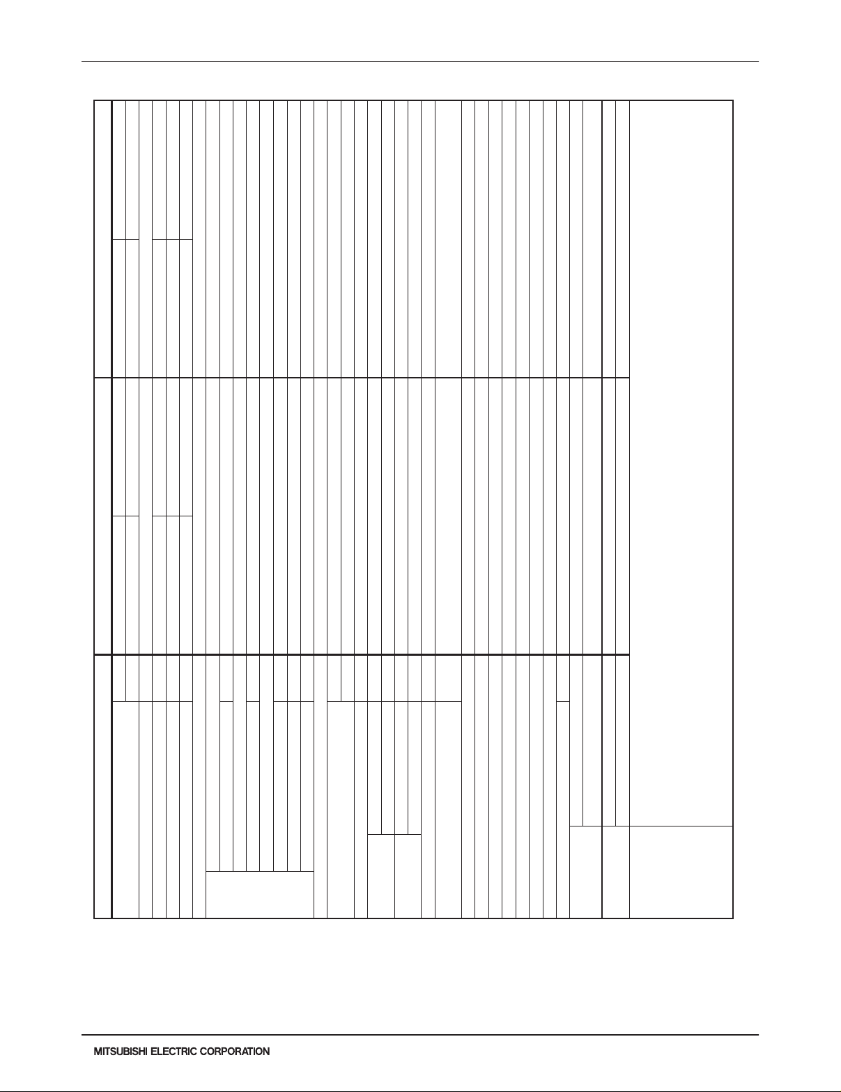
3-4. ELECTRICAL WIRING DIAGRAMS
LEDLED
H
26H
IC802
IPM,IC932
L61
DB61,DB65
C62,C63
SYMBOL
NAME SYMBOL SYMBOLNAME NAME
T801
21S4
X63,X64,X66
TB1,TB2
TR821
LEV
RT65
RT64
PTC64,PTC65
MC
RT62
RT61
MF
F701,F801,F901
RT68
(For field wiring).
NOTES:
1.About the indoor side electric
for servicing.
unit electric wiring diagram
wiring, refer to the indoor
2.Use copper conductors only.
LED
2
RED
26H
BLKBLK
2
IC932
3
L1
L2
1
CN931
5
5
GROUND
From INDOOR UNIT
CONNECTING WIRE
POWER SUPPLY
208/230V
1 phase 60Hz
TO INDOOR UNIT
CONNECTING WIRES
208/230V
1 phase 60Hz
From INDOOR UNIT
CONNECTING WIRES
DC12-24V
LD63
F701
X64
PTC64
BLK
LD-E1
PTC65
LD-S
LD62
LD61
6
INVERTER P.C. BOARD
3
F901
BLU
CN721
X63
21
1
RT65
CN643
RT62
RT61
CN641
4
1
CIRCUIT
BREAKER
BRN
BLU
BRN
RED
1
2
S3
S2
S1
TB2
TB1
RT64
RT68
CN642 CN644
2
1
CN932
L61
C62C63
LD70
LD66
DB61
DB65
+
+
+
–
–
~
~
~ ~
+
TR821
F801
T801
1
3
P
N
W
U
V
IC802
3
1
V
W
MS
3~
MSMF3~
M
LEV
MC
IPM
U
WHT
RED
BLK
3
1
RED
WHT
BLK
BLU
YLW
ORN
LDW
LDV
LDU
CN61
6
CN724
1
21S4
11
2 2
1
(OPTION PARTS)
YLW
BLK
BLK
BLK BLK
1
H
BLK
CN722
3
1
X66
4
t° t° t° t° t°
SMOOTHING CAPACITOR
DIODE MODULE
FUSE (T3.15AL250V)
DEFROST HEATER(OPTION PARTS)
INTELLIGENT POWER DEVICE
INTELLIGENT POWER MODULE
REACTOR
EXPANSION VALVE COIL
COMPRESSOR
FAN MOTOR
CIRCUIT PROTECTION
DEFROST THERMISTOR
DISCHARGE TEMP.THERMISTOR
FIN TEMP.THERMISTOR
AMBIENT TEMP.THERMISTOR
OUTDOOR HEAT EXCHANGER
TEMP. THERMISTOR.
TERMINAL BLOCK
SWITCHING POWER TRANSISTOR
TRANSFORMER
RELAY
REVERSING VALVE COIL
HEATER PROTECTOR(OPTION PARTS)
SUZ-KA09NA.TH SUZ-KA12NA.TH
SEZ Ducted Heat Pump Systems (August 2014)
Due to continuing improvement, above specication may be subject to change without notice.
© 2014 Mitsubishi Electric US, Inc.
SEZ-17
Page 18

3-4. ELECTRICAL WIRING DIAGRAMS
RT68
TB1,TB2
TR821
T801
21S4
X63,X64,X66
26H
F701,F801,F901
MF
RT61
RT62
MC
PTC64,PTC65
RT64
LEVC61,C62,C63
SYMBOL SYMBOL SYMBOLNAME NAME NAME
DB61,DB65
IC802
IPM,IC932
L61
RT65
H
LED LED
(For field wiring).
NOTES:
1.About the indoor side electric
for servicing.
unit electric wiring diagram
wiring, refer to the indoor
2.Use copper conductors only.
LED
2
RED
26H
BLKBLK
2
C61
INVERTER P.C. BOARD
F901
CN932
C62C63
LD70
LD66
DB61
DB65
–
–
~
~
~ ~
+
+
+ + +
TR821
F801
3
P
N
W
U
V
3
1
V
W
U
MS
3~
MSM3~
MC
MF
LEV
IPM
WHT
RED
BLK
3
1
RED
WHT
BLK
LDW
LDV
LDU
CN61
3
L1
L2
IC932
1
CN931
5
5
GROUND
From INDOOR UNIT
CONNECTING WIRE
POWER SUPPLY
208/230V
1 phase 60Hz
TO INDOOR UNIT
CONNECTING WIRES
208/230V
1 phase 60Hz
From INDOOR UNIT
CONNECTING WIRES
DC12-24V
LD63
F701
X64
PTC64
BLK
LD-E1
PTC65
LD-S
LD62
LD61
6
3
BLU
CN721
21
1
RT65
CN643
RT62
RT61
CN641
4
1
CIRCUIT
BREAKER
BRN
BLU
BRN
RED
1
2
S3
S2
S1
TB2
TB1
RT64
RT68
CN642 CN644
2
1
L61
T801
1
IC802
BLU
YLW
ORN
6
CN724
1
21S4
11
2 2
1
(OPTION PARTS)
YLW
BLK
BLK
BLK BLK
1
H
BLK
CN722
3
1
X63
X66
4
t° t° t° t° t°
SMOOTHING CAPACITOR
DIODE MODULE
FUSE (T3.15AL250V)
DEFROST HEATER(OPTION PARTS)
INTELLIGENT POWER DEVICE
INTELLIGENT POWER MODULE
REACTOR
EXPANSION VALVE COIL
COMPRESSOR
FAN MOTOR
CIRCUIT PROTECTION
DEFROST THERMISTOR
DISCHARGE TEMP.THERMISTOR
FIN TEMP.THERMISTOR
AMBIENT TEMP.THERMISTOR
OUTDOOR HEAT EXCHANGER
TEMP. THERMISTOR.
TERMINAL BLOCK
SWITCHING POWER TRANSISTOR
TRANSFORMER
RELAY
REVERSING VALVE COIL
HEATER PROTECTOR(OPTION PARTS)
SUZ-KA15NA.TH
Due to continuing improvement, above specication may be subject to change without notice.
SEZ-18
SEZ Ducted Heat Pump Systems (August 2014)
© 2014 Mitsubishi Electric US, Inc.
Page 19

RT68
TR821
TB1,TB2
X63,X64,X66
21S4
T801
HEATER PROTECTOR(OPTION PARTS)
26H
DB61,DB65
C61,C62,C63
SYMBOL NAME SYMBOL NAME SYMBOL NAME
DEFROST HEATER(OPTION PARTS)
L61
IC802
IPM, HC930
H
F701,F801,F901
LED
LED
RT65
RT64
RT62
RT61
PTC64,PTC65
MF
MC
LEV
LED
11
2 2
1
2
(OPTION PARTS)
YLW
RED
BLK
BLK
BLK BLK
26H
BLKBLK
2
1
H
BLK
CN722
3
1
X66
TO INDOOR UNIT
CONNECTING WIRES
208/230V
1 phase 60Hz
GROUND
FROM
INDOOR UNIT
CONNECTING WIRE
BLU
FROM
INDOOR UNIT
CONNECTING WIRES
DC12-24V
POWER SUPPLY
208/230V
1 phase 60Hz
1
1 1 1 1
5
2 3 2 4 1
INVERTER P.C. BOARD
CN931
5
21S4
CN724
6
CN61
LDU
LDV
LDW
ORN
YLW
BLU
BLK
WHT
RED
1
3
BLK
RED
WHT
U
W
MC
MF
LEV
MS
3~
MS
M
3~
V
1
3
IC802
V
U
IPM
W
N
P
3
1
HC930
T801
F801
TR821
DB65
DB61
LD66
LD70
C63 C62 C61
L61
CN932
CN644CN642
RT68
RT64
L2
L1
TB1
TB2
S1
S2
S3
BRN
2
1
RED
BRN
BLU
CIRCUIT BREAKER
CN641
RT61
RT62
CN643
RT65
3
X63
CN721
F901
6
LD61
LD62
LD-S
PTC65
LD-E1
BLK
PTC64
X64
F701
LD63
NOTES:
1. About the indoor side electric wiring, refer to the indoor unit electric
wiring diagram for servicing.
2. Use copper conductors only. (For field wiring).
~
–
+
+
+ + +
–
~ ~
~
t° t° t° t° t°
4
REACTOR
DIODE MODULE
EXPANSION VALVE COIL
COMPRESSOR
SMOOTHING CAPACITOR
FUSE (T3.15AL250V)
INTELLIGENT POWER DEVICE
INTELLIGENT POWER MODULE
FAN MOTOR
CIRCUIT PROTECTION
DEFROST THERMISTOR
DISCHARGE TEMP.THERMISTOR
FIN TEMP.THERMISTOR
AMBIENT TEMP.THERMISTOR
OUTDOOR HEAT EXCHANGER
TEMP. THERMISTOR.
TERMINAL BLOCK
SWITCHING POWER TRANSISTOR
TRANSFORMER
RELAY
REVERSING VALVE COIL
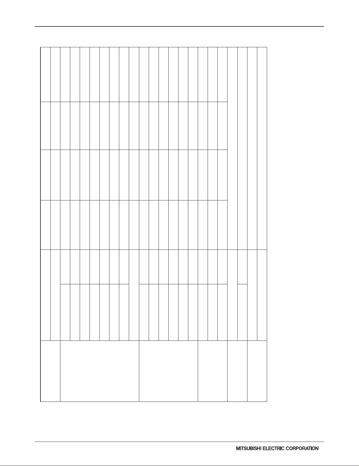
3-4. ELECTRICAL WIRING DIAGRAMS
SUZ-KA18NA.TH
Due to continuing improvement, above specication may be subject to change without notice.
© 2014 Mitsubishi Electric US, Inc.
SEZ Ducted Heat Pump Systems (August 2014)
SEZ-19
Page 20

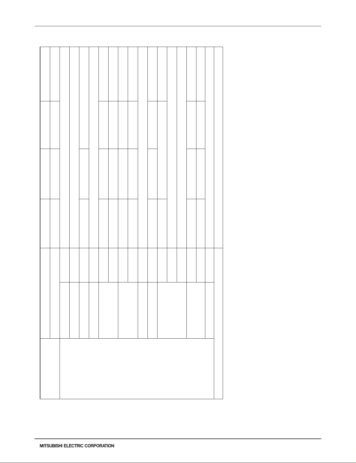
3-5. REFRIGERANT SYSTEM DIAGRAMS
SEZ-KD09NA4.TH SEZ-KD12NA4.TH SEZ-KD15NA4.TH SEZ.KD18NA4.TH
Strainer(#50)
Heat exchanger
Distributor
with strainer(#50)
Thermistor TH1
(Room temperature)
Thermistor TH5
(Cond./Eva. temperature)
Thermistor TH2
Pipe temperature (Liquid)
Refrigerant GAS pipe connection
(Flare)
Refrigerant LIQUID pipe connection
(Flare)
Strainer(#50)
Refrigerant flow in cooling
Refrigerant flow in heating
SUZ-KA09NA.TH
Refrigerant pipe ø3/8
(with heat insulator)
Flared connection
Flared connection
Refrigerant pipe ø1/4
(with heat insulator)
Muffler
Stop valve
(with service port)
Service port
Capillary tube
O.D. 0.118 × I.D. 0.079
× 9-7/16
(ø3.0 × ø2.0
Stop valve
(with strainar)
4-way valve
Discharge
temperature
thermistor
RT62
×
240)
LEV
Muffler
Service port
Compressor
Defrost
thermistor
RT61
Outdoor heat
exchanger
temperature
Outdoor
heat
exchanger
thermistor
RT68
Ambient
temperature
thermistor
RT65
Strainer
#100
R.V. coil
heating ON
cooling OFF
Refrigerant flow in cooling
Refrigerant flow in heating
Due to continuing improvement, above specication may be subject to change without notice.
SEZ-20
SEZ Ducted Heat Pump Systems (August 2014)
© 2014 Mitsubishi Electric US, Inc.
Page 21

3-5. REFRIGERANT SYSTEM DIAGRAMS
Refrigerant pipe ø3/8 (KA12)
(ø
3.6
×
ø
2.4×50)
Muffler
SUZ-KA12NA.TH SUZ-KA15NA.TH
Refrigerant pipe ø1/2 (KA15)
(with heat insulator)
Stop valve
(with service port)
Flared connection
Flared connection
Stop valve
Refrigerant pipe ø1/4
(with strainar)
(with heat insulator)
4-way valve
Muffler
Discharge
temperature
thermistor
RT62
Service port
Capillary tube
O.D. 0.118 × I.D. 0.079
× 9-7/16
×
(ø3.0 × ø2.0
240)
Muffler
Service port
Compressor
Defrost
thermistor
RT61
Capillary tube
O.D. 0.118 × I.D. 0.071
× 23-5/8
3.0
× ø
(ø
1.8
LEV
Outdoor
heat
exchanger
×
600
)
(×2)
Strainer
#100
R.V. coil
heating ON
cooling OFF
Refrigerant flow in cooling
Refrigerant flow in heating
Outdoor heat
exchanger
temperature
thermistor
RT68
Ambient
temperature
thermistor
RT65
SUZ-KA18NA.TH
Refrigerant pipe
(with heat insulator)
Flared connection
Flared connection
Refrigerant pipe ø1/4
(with heat insulator)
ø
1/2
Stop valve
(with strainar)
4-way valve
Stop valve
(with service port)
Service port
Receiver
#100
Service port
Discharge
temperature
thermistor
RT62
Compressor
LEV
Strainer
#100
Capillary tube
O.D. 0.142 × I.D. 0.094
× 1-31/32
Outdoor
Defrost
thermistor
RT61
Refrigerant flow in cooling
Refrigerant flow in heating
heat
exchanger
Outdoor heat
exchanger
temperature
thermistor
RT68
R.V. coil
heating ON
cooling OFF
Ambient
temperature
thermistor
RT65
Due to continuing improvement, above specication may be subject to change without notice.
© 2014 Mitsubishi Electric US, Inc.
SEZ Ducted Heat Pump Systems (August 2014)
SEZ-21
Page 22

3-6. CAPACITY CORRECTION CURVE BY TEMPERATURE
(1) Cooling Performance Curve
For The Combination Of Outdoor Unit SUZ-KA·NA
1.4
1.3
1.2
1.1
1.0
0.9
0.8
1.2
1.1
1.0
0.9
Indoor intake air WB temperature (°F)
71
67
63
71
67
63
Indoor intake air WB temperature (°F)
0.8
0.7
65 75 85 95 105 115
Outdoor intake air DB temperature (°F)
Due to continuing improvement, above specication may be subject to change without notice.
SEZ-22
SEZ Ducted Heat Pump Systems (August 2014)
© 2014 Mitsubishi Electric US, Inc.
Page 23

3-6. CAPACITY CORRECTION CURVE BY TEMPERATURE
65
(2) Heating Performance Curve
SEZ-KD09NA4.TH SEZ-KD12NA4.TH SEZ-KD15NA4.TH
1.3
1.2
1.1
1.0
0.9
0.8
0.7
0.6
0.5
0.4
1.1
1.0
0.9
70
75
Indoor intake air DB temperature (°F)
75
70
65
0.8
0.7
0.6
Indoor intake air DB temperature (°F)
155 25 35 45 55 65 70
Outdoor intake air WB temperature (°F)
Note :
Due to continuing improvement, above specication may be subject to change without notice.
© 2014 Mitsubishi Electric US, Inc.
This value of frequency is not the same as the actual frequency in operating.
SEZ Ducted Heat Pump Systems (August 2014)
SEZ-23
Page 24

3-6. CAPACITY CORRECTION CURVE BY TEMPERATURE
65
SEZ.KD18NA4.TH
1.3
1.2
1.1
1.0
0.9
0.8
0.7
0.6
0.5
0.4
1.1
1.0
0.9
70
75
Indoor intake air DB temperature (°F)
75
70
65
0.8
0.7
0.6
Indoor intake air DB temperature (°F)
0.5
155 25 35 45 55 65 70
Outdoor intake air WB temperature (°F)
Note :
Due to continuing improvement, above specication may be subject to change without notice.
SEZ-24
This value of frequency is not the same as the actual frequency in operating.
SEZ Ducted Heat Pump Systems (August 2014)
© 2014 Mitsubishi Electric US, Inc.
Page 25

3-7. CAPACITY CORRECTION TABLE BY TEMPERATURE
SUZ-KA09NA.TH SUZ-KA12NA.TH SUZ-KA15NA.TH
SUZ-KA15NA.TH
SUZ-KA18NA.TH
75 85 95 105 115
Btu/h)
3
TC SHC TPC TC SHC TPC TC SHC TPC TC SHC TPC TC SHC TPC
Btu/h)
3
71 9.9 6.6 0.60 9.3 6.2 0.65 8.7 5.8 0.70 8.1 5.4 0.74 7.5 5.0 0.77
67 9.4 7.5 0.56 8.7 7.0 0.62 8.1 6.5 0.67 7.5 6.0 0.71 6.9 5.5 0.74
63 8.8 8.2 0.54 8.2 7.6 0.59 7.6 7.1 0.64 6.9 6.5 0.68 6.3 5.9 0.71
71 14.1 8.8 0.82 13.2 8.3 0.90 12.4 7.7 0.97 11.5 7.2 1.02 10.6 6.6 1.06
67 13.3 10.1 0.77 12.4 9.4 0.85 11.5 8.7 0.92 10.7 8.1 0.98 9.8 7.5 1.02
63 12.5 11.2 0.74 11.6 10.4 0.81 10.8 9.7 0.88 9.8 8.8 0.94 9.0 8.0 0.98
71 17.3 11.5 1.04 16.1 10.8 1.14 15.2 10.1 1.23 14.1 9.4 1.29 13.0 8.6 1.35
67 16.4 13.1 0.98 15.2 12.2 1.08 14.1 11.3 1.17 13.1 10.5 1.24 12.1 9.6 1.30
63 15.4 14.3 0.94 14.2 13.3 1.04 13.3 12.4 1.12 12.1 11.3 1.19 11.0 10.3 1.24
71 21.1 13.8 1.23 19.7 12.9 1.35 18.5 12.1 1.45 17.2 11.3 1.52 15.8 10.4 1.59
67 20.0 15.8 1.16 18.6 14.7 1.28 17.2 13.6 1.38 16.0 12.6 1.46 14.7 11.6 1.53
63 18.7 17.3 1.10 17.4 16.0 1.22 16.2 14.9 1.32 14.7 13.6 1.41 13.4 12.4 1.46
IWB (˚ F)
Indoor air Outdoor intake air DB temperature (˚F)
Model
: 1. IWB: Intake air wet-bulb temperature
SUZ-KA09NA.TH
(1) Cooling Capacity
Due to continuing improvement, above specication may be subject to change without notice.
© 2014 Mitsubishi Electric US, Inc.
SUZ-KA12NA.TH
SUZ-KA15NA.TH
SEZ Ducted Heat Pump Systems (August 2014)
SUZ-KA18NA.TH
NOTE
TC: Total Capacity (×10
SHC: Sensible Heat Capacity (×10
TPC: Total Power Consumption (kW)
2. SHC is based on 80˚F of indoor Intake air DB temperature.
SEZ-25
Page 26

3-7. CAPACITY CORRECTION TABLE BY TEMPERATURE
SUZ-KA09NA.TH SUZ-KA12NA.TH SUZ-KA15NA.TH
SUZ-KA15NA.TH
SUZ-KA18NA.TH
Outdoor intake air WB temperature (˚ F)
5 15 25 35 43 45 55
TC TPC TC TPC TC TPC TC TPC TC TPC TC TPC TC TPC
air
Indoor
75 4.8 0.60 6.3 0.76 7.9 0.89 9.4 0.99 10.6 1.05 11.0 1.06 12.4 1.10
IDB (˚ F)
70 5.2 0.58 6.7 0.73 8.2 0.87 9.6 0.97 10.9 1.02 11.2 1.04 12.7 1.08
65 5.5 0.55 6.9 0.70 8.6 0.84 10.0 0.94 11.2 0.99 11.6 1.01 13.0 1.06
75 6.0 0.67 7.9 0.85 9.9 1.00 11.8 1.11 13.3 1.17 13.7 1.19 15.5 1.23
Model
(2) Heating Capacity
SUZ-KA09NA.TH
65 9.0 0.81 11.3 1.04 14.1 1.24 16.5 1.39 18.5 1.46 19.1 1.49 21.4 1.56
70 8.6 0.85 11.1 1.08 13.5 1.28 15.9 1.43 18.0 1.50 18.5 1.53 21.0 1.59
75 7.9 0.89 10.4 1.12 13.1 1.31 15.6 1.46 17.6 1.54 18.1 1.56 20.5 1.62
65 6.8 0.62 8.6 0.79 10.7 0.94 12.4 1.05 14.0 1.11 14.4 1.13 16.2 1.19
70 6.5 0.64 8.4 0.82 10.2 0.97 12.0 1.08 13.6 1.14 14.0 1.16 15.8 1.21
SUZ-KA12NA.TH
SUZ-KA15NA.TH
65 10.8 0.92 13.6 1.17 17.0 1.40 19.8 1.57 22.2 1.66 22.9 1.68 25.7 1.77
70 10.3 0.96 13.3 1.22 16.2 1.45 19.1 1.62 21.6 1.70 22.2 1.73 25.2 1.80
75 9.5 1.00 12.5 1.27 15.7 1.49 18.7 1.66 21.1 1.74 21.7 1.77 24.6 1.84
SUZ-KA18NA.TH
Btu/h)
3
: 1. IDB: Intake air dry-bulb temperature
EMERGENCY HEAT mode before starting to operate the air conditioner.
NOTE
TC: Total Capacity (×10
TPC: Total Power Consumption (kW)
2. Above data is for heating operation without any frost.
How to operate with xed operational frequency of the compressor.
1. Press the EMERGENCY OPERATION switch on the front of the indoor unit, and select either EMERGENCY COOL mode or
2. The compressor starts with operational frequency.
3. The fan speed of the indoor unit is High.
4. This operation continues for 30 minutes.
5. In order to release this operation, press the EMERGENCY OPERATION switch twice or once, or press any button on the
remote controller.
Due to continuing improvement, above specication may be subject to change without notice.
SEZ-26
SEZ Ducted Heat Pump Systems (August 2014)
© 2014 Mitsubishi Electric US, Inc.
Page 27

3-7. CAPACITY CORRECTION TABLE BY TEMPERATURE
(3) M-Series Cooling Correction
70 77 81 86 95 104 115
60 1.11 1.06 1.01 0.97 0.91 0.83 0.76
63 1.16 1.10 1.06 1.02 0.96 0.88 0.81
64 1.18 1.13 1.08 1.04 0.98 0.90 0.83
68 1.23 1.18 1.14 1.10 1.03 0.96 0.89
72 1.28 1.23 1.20 1.15 1.09 1.02 0.95
75 1.34 1.29 1.26 1.22 1.15 1.08 1.02
79 1.38 1.34 1.32 1.28 1.21 1.14 1.07
(4) M-Series Defrost Correction
Outdoor
intake
temperature
W.B. [° F]
Outdoor
intake
temperature
W.B. [° C]
Correction
factor
43 39 36 32 28 25 21 18 14
6 4 2 0 -2 -4 -6 -8 -10
1.00 0.80 0.82 0.84 0.87 0.90 0.93 0.96 1.00
Due to continuing improvement, above specication may be subject to change without notice.
SEZ Ducted Heat Pump Systems (August 2014)
© 2014 Mitsubishi Electric US, Inc.
SEZ-27
Page 28

3-7. CAPACITY CORRECTION TABLE BY TEMPERATURE
(5) M-Series Heating Correction
Outdoor W.B. [° F]
-13 -4 5 14 23 32 41 50
Indoor
EAT DB
SUZ-KA09NA.TH 60 0.56 0.66 0.80 0.95 1.07 1.07
SUZ-KA12NA.TH 60 0.56 0.66 0.80 0.95 1.07 1.07
SUZ-KA15NA.TH 60 0.56 0.66 0.80 0.95 1.07 1.07
SUZ-KA18NA.TH 60 0.56 0.66 0.80 0.95 1.07 1.07
Interpolated Data Between 60 and 65 Indoor EAT DB data sets
SUZ-KA09NA.TH 63 0.55 0.65 0.79 0.93 1.05 1.05
SUZ-KA12NA.TH 63 0.55 0.65 0.79 0.93 1.05 1.05
SUZ-KA15NA.TH 63 0.55 0.65 0.79 0.93 1.05 1.05
SUZ-KA18NA.TH 63 0.55 0.65 0.79 0.93 1.05 1.05
SUZ-KA09NA.TH 65 0.54 0.64 0.78 0.92 1.03 1.03
SUZ-KA12NA.TH 65 0.54 0.64 0.78 0.92 1.03 1.03
SUZ-KA15NA.TH 65 0.54 0.64 0.78 0.92 1.03 1.03
SUZ-KA18NA.TH 65 0.54 0.64 0.78 0.92 1.03 1.03
SUZ-KA09NA.TH 70 0.52 0.62 0.75 0.885 1.00 1.00
SUZ-KA12NA.TH 70 0.52 0.62 0.75 0.885 1.00 1.00
SUZ-KA15NA.TH 70 0.52 0.62 0.75 0.885 1.00 1.00
SUZ-KA18NA.TH 70 0.52 0.62 0.75 0.885 1.00 1.00
SUZ-KA09NA.TH 75 0.50 0.60 0.72 0.85 0.96 0.96
SUZ-KA12NA.TH 75 0.50 0.60 0.72 0.85 0.96 0.96
SUZ-KA15NA.TH 75 0.50 0.60 0.72 0.85 0.96 0.96
SUZ-KA18NA.TH 75 0.50 0.60 0.72 0.85 0.96 0.96
SUZ-KA09NA.TH 80 0.48 0.58 0.70 0.82 0.93 0.93
SUZ-KA12NA.TH 80 0.48 0.58 0.70 0.82 0.93 0.93
SUZ-KA15NA.TH 80 0.48 0.58 0.70 0.82 0.93 0.93
SUZ-KA18NA.TH 80 0.48 0.58 0.70 0.82 0.93 0.93
Due to continuing improvement, above specication may be subject to change without notice.
SEZ-28
SEZ Ducted Heat Pump Systems (August 2014)
© 2014 Mitsubishi Electric US, Inc.
Page 29

3-8. CAPACITY CORRECTION CURVE BY REFRIGERANT PIPING LENGTH
PERFORMANCE DATA
■COOLING CAPACITY
SUZ-KA09NA×SEZ-KD09NA4 SUZ-KA12NA×SEZ-KD12NA4
SUZ-KA15NA×SEZ-KD15NA4 SUZ-KA18NA×SEZ-KD18NA4
Indoor air Outdoor intake air DB temperature(°F)
75 85 95 105 115
TC SHC TPC TC SHC TPC TC SHC TPC TC SHC TPC TC SHC
71 9.9 6.6 0.60 9.3 6.2 0.65 8.7 5.8 0.70 8.1 5.4 0.74 7.5 5.0
67 9.4 7.5 0.56 8.7 7.0 0.62 8.1 6.5 0.67 7.5 6.0 0.71 6.9 5.5
63 8.8 8.2 0.54 8.2 7.6 0.59 7.6 7.1 0.64 6.9 6.5 0.68 6.3 5.9
71 14.1 8.8 0.82 13.2 8.3 0.90 12.4 7.7 0.97 11.5 7.2 1.02 10.6 6.6
67 13.3 10.1 0.77 12.4 9.4 0.85 11.5 8.7 0.92 10.7 8.1 0.98 9.8 7.5
63 12.5 11.2 0.74 11.6 10.4 0.81 10.8 9.7 0.88 9.8 8.8 0.94 9.0 8.0
71 17.3 11.5 1.04 16.1 10.8 1.14 15.2 10.1 1.23 14.1 9.4 1.29 13.0 8.6
67 16.4 13.1 0.98 15.2 12.2 1.08 14.1 11.3 1.17 13.1 10.5 1.24 12.1 9.6
63 15.4 14.3 0.94 14.2 13.3 1.04 13.3 12.4 1.12 12.1 11.3 1.19 11.0 10.3
71 21.1 13.8 1.23 19.7 12.9 1.35 18.5 12.1 1.45 17.2 11.3 1.52 15.8 10.4
67 20.0 15.8 1.16 18.6 14.7 1.28 17.2 13.6 1.38 16.0 12.6 1.46 14.7 11.6
63 18.7 17.3 1.10 17.4 16.0 1.22 16.2 14.9 1.32 14.7 13.6 1.41 13.4 12.4
SUZ-KA09NA×SLZ-KA09NA SUZ-KA12NA×SLZ-KA12NA
SUZ-KA15NA×SLZ-KA15NA
Indoor air Outdoor intake air DB temperature(°F)
75 85 95 105 115
TC SHC TPC TC SHC TPC TC SHC TPC TC SHC TPC TC SHC
71 10.3 7.3 0.62 9.6 6.8 0.68 9.0 6.4 0.74 8.4 5.9 0.77 7.7 5.5
67 9.7 8.2 0.59 9.1 7.6 0.65 8.4 7.1 0.70 7.8 6.6 0.74 7.2 6.0
63 9.2 8.9 0.56 8.5 8.3 0.62 7.9 7.7 0.67 7.2 7.0 0.71 6.6 6.4
71 13.6 8.7 0.82 12.7 8.1 0.90 11.9 7.6 0.97 11.1 7.1 1.02 10.2 6.5
67 12.9 9.9 0.77 12.0 9.2 0.85 11.1 8.5 0.92 10.3 7.9 0.98 9.5 7.3
63 12.1 10.9 0.74 11.2 10.1 0.81 10.4 9.4 0.88 9.5 8.6 0.94 8.7 7.8
71 18.4 9.9 1.30 17.2 9.2 1.42 16.1 8.7 1.53 15.0 8.1 1.61 13.8 7.4
67 17.4 11.7 1.23 16.2 10.9 1.35 15.0 10.1 1.46 14.0 9.3 1.55 12.8 8.6
63 16.4 13.1 1.17 15.2 12.2 1.29 14.1 11.3 1.39 12.8 10.3 1.49 11.7 9.4
NOTE:1. IWB:Intake air wet-bulb temperature
TC:Total Ca
p
acity (×103Btu/h)
SHC:Sensible Heat Ca
p
acity (×103Btu/h)
TPC:Total Power Consumption (kW)
2. SHC is based on 80°F of indoor intake air DB temperature.
C
OOLING CAPACITY CORRECTION
SUZ-KA15NA
Model
Model
SUZ-KA09NA
SUZ-KA12NA
IWB(°F)
SUZ-KA09NA
IWB(°F)
SUZ-KA18NA
SUZ-KA12NA
SUZ-KA15NA
Mode
l
Refrigerant piping length (one way : ft.
)
25(std.) 40 65 100
SUZ-KA09NA
SUZ-KA12NA
SUZ-KA15NA
SUZ-KA18NA 1.0 0.954 0.878 0.771
0.878 -1.0 0.954
SUZ-KA09NA.TH SUZ-KA12NA.TH SUZ-KA15NA.TH
SUZ-KA15NA.TH
SUZ-KA18NA.TH
1.00
0.95
0.90
0.85
0.80
Cooling capacity corrections
0.75
0.70
0 10 20 30 40 50 60 70 80 90 100 110
Refrigerant piping length (ft)
Due to continuing improvement, above specication may be subject to change without notice.
© 2014 Mitsubishi Electric US, Inc.
SEZ Ducted Heat Pump Systems (August 2014)
SEZ-29
Page 30

Max. Height
difference
B
Additional Piping
Max. length
A
Indoor
unit
Outdoor unit
3-9. CAPACITY CORRECTION TABLE BY REFRIGERANT PIPING LENGTH
(1) Cooling capacity correction
Refrigerant piping length (one way: ft.)
25 (std.) 40 65 100
SUZ-KA09NA.TH
SUZ-KA12NA.TH
SUZ-KA15NA.TH
1.0 0.954 0.878 -
SUZ-KA18NA.TH
1.0 0.954 0.878 0.713
(2) Maximum refrigerant piping length & maximum height difference
Refrigerant piping: ft Piping size: in.
Model
SUZ-KA09NA.TH
SUZ-KA12NA.TH
SUZ-KA15NA.TH
SUZ-KA18NA.TH
Additional
piping
Max. length
A
65 40
65 40
100 50
Additional
piping
Max. height
B
Outside
diameter
Gas Liquid
Minimum
3/8
1/2
1/2
Wall
thickness
0.0315
0.0315
0.0315
diameter
Outside
1/4
1/4
1/4
Minimum
Wall
thickness
0.0315
0.0315
0.0315
Due to continuing improvement, above specication may be subject to change without notice.
SEZ-30
SEZ Ducted Heat Pump Systems (August 2014)
© 2014 Mitsubishi Electric US, Inc.
Page 31

3-9. CAPACITY CORRECTION TABLE BY REFRIGERANT PIPING LENGTH
(3) M-Series Piping Correction Cooling
Refrigerant piping length (ft)
25(std) 40 65 100
1.000 0.954 0.878 0.771
(4) M-Series Piping Correction Heating
Refrigerant piping length (ft)
25(std) 40 65 100
1.000 0.989 0.972 0.955
Due to continuing improvement, above specication may be subject to change without notice.
SEZ Ducted Heat Pump Systems (August 2014)
© 2014 Mitsubishi Electric US, Inc.
SEZ-31
Page 32

3-10. CHARGE CALCULATIONS
(1) Additional Refrigerant Charge (R410A: oz.)
NOTE: Refrigerant piping exceeding 25 ft. requires additional refrigerant charge according to the calcualation.
Refrigerant piping length (one way): ft.
Model
Outdoor unit
precharged
25ft 30ft 40ft 50ft 60ft 65ft
SUZ-KA09NA.TH
SUZ-KA12NA.TH
SUZ-KA15NA.TH
NOTE: Calculation: X oz. = 1.62/5 oz./ft (Refrigerant piping length (ft) - 25)
Model
SUZ-KA18NA.TH
NOTE: Calculation: X oz. = 1.08/5 oz./ft (Refrigerant piping length (ft) - 25)
2 lb. 0 oz.
0 1.62 4.86 8.10 11.34 12.96
2 lb. 9 oz.
Refrigerant piping length (one way): ft.
Outdoor unit
precharged
25ft 30ft 40ft 50ft 60ft 70ft 80ft 90ft 100ft
4 lb. 0 oz. 0 1.08 3.24 5.40 7.56 9.72 11.88 14.04 16.20
Due to continuing improvement, above specication may be subject to change without notice.
SEZ-32
SEZ Ducted Heat Pump Systems (August 2014)
© 2014 Mitsubishi Electric US, Inc.
Page 33

3-11. AIR FLOW DATA
(1) Indoor Unit
SEZ-KD09NA4.TH
(External static pressure 0.02[in.WG](5Pa)) 208/230V 60Hz
40
[0.16]
30
[0.12]
20
[0.08]
External static pressure [in.WG](Pa)
10
[0.04]
Low
0
4 567 8 9 10
456789 10
[141] [176] [212] [247] [282] [318] [353]
[141] [176] [212] [247] [282] [318] [353]
Middle
Airflow rate(m
Airflow rate(m
3
3
/min)[CFM]
/min)[CFM]
Limit
High
Rated point
SEZ-KD09NA4.TH
(External static pressure 0.14[in.WG](35Pa)) 208/230V 60Hz
80
[0.32]
70
[0.28]
60
[0.24]
50
[0.20]
40
[0.16]
30
[0.12]
External static pressure [in.WG](Pa)
20
[0.08]
10
[0.04]
0
45678910
[141] [176] [212] [247] [282] [318] [353]
Low
Airflow rate(m
Middle
Limit
Rated point
3
/min)[CFM]
High
SEZ-KD09NA4.TH
(External static pressure 0.06[in.WG](15Pa)) 208/230V 60Hz
50
[0.20]
40
[0.16]
30
[0.12]
20
[0.08]
External static pressure [in.WG](Pa)
10
[0.04]
0
456 78910
[141] [176] [212] [247] [282] [318] [353]
Low
Middle
Airflow rate(m
High
3
/min)[CFM]
Limit
Rated point
SEZ-KD09NA4.TH
(External static pressure 0.20[in.WG](50Pa)) 208/230V 60Hz
80
[0.32]
70
[0.28]
60
[0.24]
50
[0.20]
40
[0.16]
30
[0.12]
External static pressure [in.WG](Pa)
20
[0.08]
10
[0.04]
0
45678910
[141] [176] [212] [247] [282] [318] [353]
Low
Middle
Airflow rate(m
Limit
3
/min)[CFM]
High
Rated point
Due to continuing improvement, above specication may be subject to change without notice.
SEZ Ducted Heat Pump Systems (August 2014)
© 2014 Mitsubishi Electric US, Inc.
SEZ-33
Page 34

3-11. AIR FLOW DATA
SEZ-KD12NA4.TH
(External static pressure 0.02[in.WG](5Pa)) 208/230V 60Hz
40
[0.16]
30
[0.12]
20
[0.08]
External static pressure [in.WG](Pa)
10
[0.04]
Low
0
6789 10 11 12
[212] [282] ]883[]353[]742[ ]424[]813[
Middle
Airflow rate(m
3
/min)[CFM]
High
Rated point
SEZ-KD12NA4.TH
(External static pressure 0.14[in.WG](35Pa)) 208/230V 60Hz
80
[0.32]
70
[0.28]
60
[0.24]
50
[0.20]
40
[0.16]
Middle
3
/min)[CFM]
Rated point
30
[0.12]
External static pressure [in.WG](Pa)
20
[0.08]
10
[0.04]
0
6789 10 11 12
[212] [282] ]883[]353[]742[ ]424[]813[
Low
Airflow rate(m
Limit
Limit
High
SEZ-KD12NA4.TH
(External static pressure 0.06[in.WG](15Pa)) 208/230V 60Hz
50
[0.20]
40
[0.16]
30
[0.12]
20
[0.08]
External static pressure [in.WG](Pa)
10
[0.04]
0
6789 10 11 12
[212] [282] ]883[]353[]742[ ]424[]813[
Low
Middle
Airflow rate(m
3
/min)[CFM]
High
Rated point
SEZ-KD12NA4.TH
(External static pressure 0.20[in.WG](50Pa)) 208/230V 60Hz
80
[0.32]
70
[0.28]
60
[0.24]
50
[0.20]
40
[0.16]
30
[0.12]
External static pressure [in.WG](Pa)
20
[0.08]
10
[0.04]
0
6789 10 11 12
[212] [282] ]883[]353[]742[ ]424[]813[
Low
Airflow rate(m
Middle
3
Limit
Rated point
/min)[CFM]
Limit
High
Due to continuing improvement, above specication may be subject to change without notice.
SEZ-34
SEZ Ducted Heat Pump Systems (August 2014)
© 2014 Mitsubishi Electric US, Inc.
Page 35

3-11. AIR FLOW DATA
SEZ-KD15NA4.TH
(External static pressure 0.02[in.WG](5Pa)) 208/230V 60Hz
40
[0.16]
30
[0.12]
20
[0.08]
External static pressure [in.WG](Pa)
10
[0.04]
0
8 9 10 11 12 13 14 15 16
[282] [318] [353] [388] [424] [494][459] [530] [565]
Low
Middle
Airflow rate(m
3
/min)[CFM]
High
Rated point
SEZ-KD15NA4.TH
(External static pressure 0.14[in.WG](35Pa)) 208/230V 60Hz
80
[0.32]
70
[0.28]
60
[0.24]
50
[0.20]
40
[0.16]
Airflow rate(m
Middle
3
/min)[CFM]
30
[0.12]
External static pressure [in.WG](Pa)
20
[0.08]
10
[0.04]
0
8 9 10 11 12 13 14 15 16
[282] [318] [353] [388] [424] [494][459] [530] [565]
Low
Limit
High
Rated point
Limit
SEZ-KD15NA4.TH
(External static pressure 0.06[in.WG](15Pa)) 208/230V 60Hz
50
[0.20]
40
[0.16]
30
[0.12]
20
[0.08]
External static pressure [in.WG](Pa)
10
[0.04]
0
8 9 10 11 12 13 14 15 16
[282] [318] [353] [388] [424] [494][459] [530] [565]
Low
Middle
Airflow rate(m
3
/min)[CFM]
High
Rated point
SEZ-KD15NA4.TH
(External static pressure 0.20[in.WG](50Pa)) 208/230V 60Hz
80
[0.32]
70
[0.28]
60
[0.24]
50
[0.20]
40
[0.16]
30
[0.12]
External static pressure [in.WG](Pa)
20
[0.08]
10
[0.04]
0
8 9 10 11 12 13 14 15 16
[282] [318] [353] [388] [424] [494][459] [530] [565]
Low
Airflow rate(m
Middle
3
/min)[CFM]
Limit
High
Rated point
Limit
Due to continuing improvement, above specication may be subject to change without notice.
SEZ Ducted Heat Pump Systems (August 2014)
© 2014 Mitsubishi Electric US, Inc.
SEZ-35
Page 36

3-11. AIR FLOW DATA
SEZ-KD18NA4.TH
(External static pressure 0.02[in.WG](5Pa)) 208/230V 60Hz
40
[0.16]
Limit
30
[0.12]
20
[0.08]
External static pressure [in.WG](Pa)
10
[0.04]
Low
0
9 10 11 12 13 14 15 16 17 18 19
[318] [353] [388] [424] [494][459] [530] [565] [600] [671][636]
Middle
Airflow rate(m
High
3
/min)[CFM]
Rated point
SEZ-KD18NA4.TH
(External static pressure 0.14[in.WG](35Pa)) 208/230V 60Hz
80
[0.32]
70
[0.28]
60
[0.24]
50
[0.20]
40
[0.16]
30
[0.12]
External static pressure [in.WG](Pa)
20
[0.08]
10
[0.04]
0
9 10 11 12 13 14 15 16 17 18 19
[318] [353] [388] [424] [494][459] [530] [565] [600] [671][636]
Low
Middle
Airflow rate(m
3
/min)[CFM]
Limit
High
Rated point
SEZ-KD18NA4.TH
(External static pressure 0.06[in.WG](15Pa)) 208/230V 60Hz
50
[0.20]
Limit
40
[0.16]
High
30
[0.12]
Middle
20
[0.08]
External static pressure [in.WG](Pa)
10
[0.04]
0
9 10 11 12 13 14 15 16 17 18 19
[318] [353] [388] [424] [494][459] [530] [565] [600] [671][636]
Low
Airflow rate(m
3
/min)[CFM]
Rated point
SEZ-KD18NA4.TH
(External static pressure 0.20[in.WG](50Pa)) 208/230V 60Hz
80
[0.32]
70
[0.28]
60
[0.24]
50
[0.20]
40
[0.16]
30
[0.12]
External static pressure [in.WG](Pa)
20
[0.08]
10
[0.04]
0
9 10 11 12 13 14 15 16 17 18 19
[318] [353] [388] [424] [494][459] [530] [565] [600] [671][636]
Low
Airflow rate(m
Limit
Middle
3
/min)[CFM]
High
Rated point
Due to continuing improvement, above specication may be subject to change without notice.
SEZ-36
SEZ Ducted Heat Pump Systems (August 2014)
© 2014 Mitsubishi Electric US, Inc.
Page 37

3-12. SOUND PRESSURE LEVELS
90
80
70
60
50
40
30
20
10
63 125 250 500 1000 2000 4000 8000
APPROXIMATE
THRESHOLD OF
HEARING FOR
CONTINUOUS
NOISE
NC-60
NC-50
NC-40
NC-30
NC-20
NC-70
OCTAVE BAND SOUND PRESSURE LEVEL, dB (0 dB = 0.0002 µbar)
BAND CENTER FREQUENCIES, Hz
SEZ-KD09NA4.TH
External static pressure:
0.06[in.WG](15Pa)
High
Middle
30
SPL(dB)
26
Low
23
LINE
<60Hz>
NOTCH
90
80
70
60
50
40
30
20
10
63 125 250 500 1000 2000 4000 8000
APPROXIMATE
THRESHOLD OF
HEARING FOR
CONTINUOUS
NOISE
NC-60
NC-50
NC-40
NC-30
NC-20
NC-70
OCTAVE BAND SOUND PRESSURE LEVEL, dB (0 dB = 0.0002 µbar)
BAND CENTER FREQUENCIES, Hz
SEZ-KD09NA4.TH
External static pressure:
0.02[in.WG](5Pa)
High
Middle
29
SPL(dB)
25
Low
22
LINE
<60Hz>
NOTCH
90
80
70
60
50
40
30
20
10
63 125 250 500 1000 2000 4000 8000
APPROXIMATE
THRESHOLD OF
HEARING FOR
CONTINUOUS
NOISE
NC-60
NC-50
NC-40
NC-30
NC-20
NC-70
OCTAVE BAND SOUND PRESSURE LEVEL, dB (0 dB = 0.0002 µbar)
BAND CENTER FREQUENCIES, Hz
SEZ-KD09NA4.TH
External static pressure:
0.20[in.WG](50Pa)
High
Middle
33
SPL(dB)
29
Low
25
LINE
<60Hz>
NOTCH
90
80
70
60
50
40
30
20
10
63 125 250 500 1000 2000 4000 8000
APPROXIMATE
THRESHOLD OF
HEARING FOR
CONTINUOUS
NOISE
NC-60
NC-50
NC-40
NC-30
NC-20
NC-70
OCTAVE BAND SOUND PRESSURE LEVEL, dB (0 dB = 0.0002 µbar)
BAND CENTER FREQUENCIES, Hz
SEZ-KD09NA4.TH
External static pressure:
0.14[in.WG](35Pa)
High
Middle
31
SPL(dB)
28
Low
24
LINE
<60Hz>
NOTCH
INDOOR UNIT
NOTE: The sound level is measured in an anechoic room where echoes are few, when compressor stops. The sound
may be bigger than displayed level under actual installation condition by surrounding echoes. The sound level
can be higher by about 2 dB than the displayed level during cooling and heating operation.
(1) Indoor Unit
Due to continuing improvement, above specication may be subject to change without notice.
© 2014 Mitsubishi Electric US, Inc.
SEZ Ducted Heat Pump Systems (August 2014)
SEZ-37
Page 38

3-12. SOUND PRESSURE LEVELS
90
80
70
60
50
40
30
20
10
63 125 250 500 1000 2000 4000 8000
APPROXIMATE
THRESHOLD OF
HEARING FOR
CONTINUOUS
NOISE
NC-60
NC-50
NC-40
NC-30
NC-20
NC-70
OCTAVE BAND SOUND PRESSURE LEVEL, dB (0 dB = 0.0002 µbar)
BAND CENTER FREQUENCIES, Hz
SEZ-KD12NA4.TH
External static pressure:
0.06[in.WG](15Pa)
High
Middle
33
SPL(dB)
28
Low
23
LINE
<60Hz>
NOTCH
90
80
70
60
50
40
30
20
10
63 125 250 500 1000 2000 4000 8000
APPROXIMATE
THRESHOLD OF
HEARING FOR
CONTINUOUS
NOISE
NC-60
NC-50
NC-40
NC-30
NC-20
NC-70
OCTAVE BAND SOUND PRESSURE LEVEL, dB (0 dB = 0.0002 µbar)
BAND CENTER FREQUENCIES, Hz
SEZ-KD12NA4.TH
External static pressure:
0.02[in.WG](5Pa)
High
Middle
33
SPL(dB)
28
Low
23
LINE
<60Hz>
NOTCH
90
80
70
60
50
40
30
20
10
63 125 250 500 1000 2000 4000 8000
APPROXIMATE
THRESHOLD OF
HEARING FOR
CONTINUOUS
NOISE
NC-60
NC-50
NC-40
NC-30
NC-20
NC-70
OCTAVE BAND SOUND PRESSURE LEVEL, dB (0 dB = 0.0002 µbar)
BAND CENTER FREQUENCIES, Hz
SEZ-KD12NA4.TH
External static pressure:
0.20[in.WG](50Pa)
High
Middle
35
SPL(dB)
31
Low
25
LINE
<60Hz>
NOTCH
90
80
70
60
50
40
30
20
10
63 125 250 500 1000 2000 4000 8000
APPROXIMATE
THRESHOLD OF
HEARING FOR
CONTINUOUS
NOISE
NC-60
NC-50
NC-40
NC-30
NC-20
NC-70
OCTAVE BAND SOUND PRESSURE LEVEL, dB (0 dB = 0.0002 µbar)
BAND CENTER FREQUENCIES, Hz
SEZ-KD12NA4.TH
External static pressure:
0.14[in.WG](35Pa)
High
Middle
34
SPL(dB)
29
Low
24
LINE
<60Hz>
NOTCH
NOTE: The sound level is measured in an anechoic room where echoes are few, when compressor stops. The sound
may be bigger than displayed level under actual installation condition by surrounding echoes. The sound level
can be higher by about 2 dB than the displayed level during cooling and heating operation.
Due to continuing improvement, above specication may be subject to change without notice.
SEZ-38
SEZ Ducted Heat Pump Systems (August 2014)
© 2014 Mitsubishi Electric US, Inc.
Page 39

3-12. SOUND PRESSURE LEVELS
90
80
70
60
50
40
30
20
10
63 125 250 500 1000 2000 4000 8000
APPROXIMATE
THRESHOLD OF
HEARING FOR
CONTINUOUS
NOISE
NC-60
NC-50
NC-40
NC-30
NC-20
NC-70
OCTAVE BAND SOUND PRESSURE LEVEL, dB (0 dB = 0.0002 µbar)
BAND CENTER FREQUENCIES, Hz
SEZ-KD15NA4.TH
External static pressure:
0.06[in.WG](15Pa)
High
Middle
37
SPL(dB)
34
Low
30
LINE
<60Hz>
NOTCH
90
80
70
60
50
40
30
20
10
63 125 250 500 1000 2000 4000 8000
APPROXIMATE
THRESHOLD OF
HEARING FOR
CONTINUOUS
NOISE
NC-60
NC-50
NC-40
NC-30
NC-20
NC-70
OCTAVE BAND SOUND PRESSURE LEVEL, dB (0 dB = 0.0002 µbar)
BAND CENTER FREQUENCIES, Hz
SEZ-KD15NA4.TH
External static pressure:
0.02[in.WG](5Pa)
High
Middle
36
SPL(dB)
33
Low
29
LINE
<60Hz>
NOTCH
90
80
70
60
50
40
30
20
10
63 125 250 500 1000 2000 4000 8000
APPROXIMATE
THRESHOLD OF
HEARING FOR
CONTINUOUS
NOISE
NC-60
NC-50
NC-40
NC-30
NC-20
NC-70
OCTAVE BAND SOUND PRESSURE LEVEL, dB (0 dB = 0.0002 µbar)
BAND CENTER FREQUENCIES, Hz
SEZ-KD15NA4.TH
External static pressure:
0.20[in.WG](50Pa)
High
Middle
39
SPL(dB)
36
Low
32
LINE
<60Hz>
NOTCH
90
80
70
60
50
40
30
20
10
63 125 250 500 1000 2000 4000 8000
APPROXIMATE
THRESHOLD OF
HEARING FOR
CONTINUOUS
NOISE
NC-60
NC-50
NC-40
NC-30
NC-20
NC-70
OCTAVE BAND SOUND PRESSURE LEVEL, dB (0 dB = 0.0002 µbar)
BAND CENTER FREQUENCIES, Hz
SEZ-KD15NA4.TH
External static pressure:
0.14[in.WG](35Pa)
High
Middle
38
SPL(dB)
35
Low
31
LINE
<60Hz>
NOTCH
NOTE: The sound level is measured in an anechoic room where echoes are few, when compressor stops. The sound
may be bigger than displayed level under actual installation condition by surrounding echoes. The sound level
can be higher by about 2 dB than the displayed level during cooling and heating operation.
Due to continuing improvement, above specication may be subject to change without notice.
© 2014 Mitsubishi Electric US, Inc.
SEZ Ducted Heat Pump Systems (August 2014)
SEZ-39
Page 40

3-12. SOUND PRESSURE LEVELS
90
80
70
60
50
40
30
20
10
63 125 250 500 1000 2000 4000 8000
APPROXIMATE
THRESHOLD OF
HEARING FOR
CONTINUOUS
NOISE
NC-60
NC-50
NC-40
NC-30
NC-20
NC-70
OCTAVE BAND SOUND PRESSURE LEVEL, dB (0 dB = 0.0002 µbar)
BAND CENTER FREQUENCIES, Hz
SEZ-KD18NA4.TH
External static pressure:
0.06[in.WG](15Pa)
High
Middle
38
SPL(dB)
34
Low
30
LINE
<60Hz>
NOTCH
90
80
70
60
50
40
30
20
10
63 125 250 500 1000 2000 4000 8000
APPROXIMATE
THRESHOLD OF
HEARING FOR
CONTINUOUS
NOISE
NC-60
NC-50
NC-40
NC-30
NC-20
NC-70
OCTAVE BAND SOUND PRESSURE LEVEL, dB (0 dB = 0.0002 µbar)
BAND CENTER FREQUENCIES, Hz
SEZ-KD18NA4.TH
External static pressure:
0.02[in.WG](5Pa)
High
Middle
37
SPL(dB)
33
Low
29
LINE
<60Hz>
NOTCH
90
80
70
60
50
40
30
20
10
63 125 250 500 1000 2000 4000 8000
APPROXIMATE
THRESHOLD OF
HEARING FOR
CONTINUOUS
NOISE
NC-60
NC-50
NC-40
NC-30
NC-20
NC-70
OCTAVE BAND SOUND PRESSURE LEVEL, dB (0 dB = 0.0002 µbar)
BAND CENTER FREQUENCIES, Hz
SEZ-KD18NA4.TH
External static pressure:
0.20[in.WG](50Pa)
High
Middle
39
SPL(dB)
36
Low
32
LINE
<60Hz>
NOTCH
90
80
70
60
50
40
30
20
10
63 125 250 500 1000 2000 4000 8000
APPROXIMATE
THRESHOLD OF
HEARING FOR
CONTINUOUS
NOISE
NC-60
NC-50
NC-40
NC-30
NC-20
NC-70
OCTAVE BAND SOUND PRESSURE LEVEL, dB (0 dB = 0.0002 µbar)
BAND CENTER FREQUENCIES, Hz
SEZ-KD18NA4.TH
External static pressure:
0.14[in.WG](35Pa)
High
Middle
39
SPL(dB)
35
Low
31
LINE
<60Hz>
NOTCH
NOTE: The sound level is measured in an anechoic room where echoes are few, when compressor stops. The sound
may be bigger than displayed level under actual installation condition by surrounding echoes. The sound level
can be higher by about 2 dB than the displayed level during cooling and heating operation.
Due to continuing improvement, above specication may be subject to change without notice.
SEZ-40
SEZ Ducted Heat Pump Systems (August 2014)
© 2014 Mitsubishi Electric US, Inc.
Page 41

3-12. SOUND PRESSURE LEVELS
90
80
70
60
50
40
30
20
10
63 125 250 500 1000 2000 4000 8000
NC-60
NC-50
NC-40
NC-30
NC-20
NC-70
BAND CENTER FREQUENCIES, Hz
APPROXIMATE
THRESHOLD OF
HEARING FOR
CONTINUOUS
NOISE
COOLING
FUNCTION
SPL(dB(A))
LINE
HEATING4650
OCTAVE BAND SOUND PRESSURE LEVEL, dB (0 dB = 0.0002 bar)
SUZ-KA09NA.TH
90
80
70
60
50
40
30
20
10
63 125 250 500 1000 2000 4000 8000
NC-60
NC-50
NC-40
NC-30
NC-20
NC-70
BAND CENTER FREQUENCIES, Hz
APPROXIMATE
THRESHOLD OF
HEARING FOR
CONTINUOUS
NOISE
COOLING
FUNCTION
SPL(dB(A))
LINE
HEATING4951
OUTDOOR UNIT
MICROPHONE
1m
OCTAVE BAND SOUND PRESSURE LEVEL, dB (0 dB = 0.0002 bar)
SUZ-KA12NA.TH
COOLING
FUNCTION
SPL(dB(A)) LINE
HEATING5456
90
80
70
60
50
40
30
20
10
63 125 250 500 1000 2000 4000 8000
NC-60
NC-50
NC-40
NC-30
NC-20
NC-70
BAND CENTER FREQUENCIES, Hz
APPROXIMATE
THRESHOLD OF
HEARING FOR
CONTINUOUS
NOISE
OCTAVE BAND SOUND PRESSURE LEVEL, dB (0 dB = 0.0002 bar)
SUZ-KA18NA.TH
OUTDOOR UNIT
90
80
70
60
50
40
30
20
10
63 125 250 500 1000 2000 4000 8000
NC-60
NC-50
NC-40
NC-30
NC-20
NC-70
BAND CENTER FREQUENCIES, Hz
APPROXIMATE
THRESHOLD OF
HEARING FOR
CONTINUOUS
NOISE
COOLING
FUNCTION
SPL(dB(A))
LINE
HEATING4951
OCTAVE BAND SOUND PRESSURE LEVEL, dB (0 dB = 0.0002 bar)
SUZ-KA15NA.TH
(2) Outdoor Unit
Due to continuing improvement, above specication may be subject to change without notice.
© 2014 Mitsubishi Electric US, Inc.
SEZ Ducted Heat Pump Systems (August 2014)
SEZ-41
Page 42

3-13. STANDARD OPERATION RANGE
Rating Guaranteed Voltage
Outdoor unit
Mode
Cooling
Heating
208/230V
60Hz
Min. 187V
208V
230V
Max. 253V
1 Phase
Intake Air Temperature Indoor Outdoor
Condition DB (°F) WB (°F) DB (°F) WB (°F)
Standard temperature 80 67 95 —
Maximum temperature 90 73 115 —
Minimum temperature 67 57 14 —
Maximum humidity 78% —
Standard temperature 70 60 47 43
Maximum temperature 80 67 75 65
Minimum temperature 70 60 6 5
Due to continuing improvement, above specication may be subject to change without notice.
SEZ-42
SEZ Ducted Heat Pump Systems (August 2014)
© 2014 Mitsubishi Electric US, Inc.
Page 43

3-14. ACCESSORIES
(1) Indoor Unit
Part Number Descriptions Applicable model
BRP-1
BRP-2
BRP-3
C13-103 Blue Diamond Sensor Extension Cable - 15 Ft.
DPLS1
FBL 1-1 FB SERIES Filter Box with MERV 8 Filters KD09
FBL 1-2 FB SERIES Filter Box with MERV 8 Filters KD12,15
Bottom Return Plate (Converts low prole ducted indoor
unit from rear return to bottom return)
Bottom Return Plate (Converts low prole ducted indoor
unit from rear return to bottom return)
Bottom Return Plate (Converts low prole ducted indoor
unit from rear return to bottom return)
Relay Kit for external heater adapter connects to CN24 on
indoor control board
Drain Pan Level Sensor/Control for indoor unit shut off to
prevent Drain Pan Overow
KD09
KD12,15
KD18
All ModelsCN24RELAY-KIT-CM3
FBL 1-3 FB SERIES Filter Box with MERV 8 Filters KD18
System Control Interface - MA, Contact terminal, and
MAC-333IF-E
MCCH1
MHK1
MOS1
M-NET Control Adapter, Supplemental heat and humidier
adaptor
Portable Central Controller (PCC) - controls up to 16
RedLINK Zones - requires an MHK1 on each indoor unit
All Models
Wireless wall-mounted remote controller (MRCH1) with a
signal receiver (MIFH1) and cable (MRC1) all in one kit
Outdoor Air Sensor - reads both outside temperature and
humidity displayed on MRCH1 and MCCH1 if installed
Due to continuing improvement, above specication may be subject to change without notice.
SEZ Ducted Heat Pump Systems (August 2014)
© 2014 Mitsubishi Electric US, Inc.
SEZ-43
Page 44

3-14. ACCESSORIES
(1) Indoor Unit (cont.)
Part Number Descriptions Applicable model
PAC-715AD Wire for Remote on/off with CN32 connector
PAC-725AD
PAC-SE41TS-E Remote temperature sensor for indoor units
PAC-SF40RM-E
PAR-FA32MA Wireless Signal Receiver used with PAR-FL32MA
PAR-FL32MA Wireless Remote Controller used with PAR-FA32MA
PAC-YT53CRAU Simple MA Remote Controller
PAR-31MAA
RCMKP1CB
Connector and wire for Operation status/error, booster fan
control for fresh air using CN51
Remote Operation Adapter with wire terminals for remote
on/off and operation status/error
Wall mounted, hard wired, multi-functional controller: used
specically for grouping (up to 16 units), twinning, lead/lag,
and 7 day programmable applications
Lockdown Bracket for wireless, hand-held, remote
controllers
All Models
SI30-115 Mini-Condensation pump - 115 volt application
SI30-230 Mini-Condensation pump - 230 volt application
TAZ-MS303
Due to continuing improvement, above specication may be subject to change without notice.
SEZ-44
Advanced Blue Diamond Mini-Condensation pump w/
Resevoir & Sensor - 208/230 volt application
SEZ Ducted Heat Pump Systems (August 2014)
© 2014 Mitsubishi Electric US, Inc.
Page 45

3-14. ACCESSORIES
(1) Indoor Unit (cont.)
Part Number Descriptions Applicable model
MLS143812T-15
MLS143812T-30 1/4 x 3/8 x 30' / 1/2" Twin-Tube Insulation
MLS143812T-50 1/4 x 3/8 x 50' / 1/2" Twin-Tube Insulation
MLS143812T-65 1/4 x 3/8 x 65' / 1/2" Twin-Tube Insulation
MLS141212T-15 1/4 x 1/2 x 15' / 1/2" Twin-Tube Insulation
MLS141212T-30 1/4 x 1/2 x 30' / 1/2" Twin-Tube Insulation
MLS141212T-50 1/4 x 1/2 x 50' / 1/2" Twin-Tube Insulation
MLS141212T-65 1/4 x 1/2 x 65' / 1/2" Twin-Tube Insulation
Diamondback
Linesets
1/4 x 3/8 x 15' / 1/2" Twin-Tube Insulation
KD09,12
KD15,18
MLS141212T-100 1/4 x 1/2 x 100' / 1/2" Twin-Tube Insulation
Due to continuing improvement, above specication may be subject to change without notice.
SEZ Ducted Heat Pump Systems (August 2014)
© 2014 Mitsubishi Electric US, Inc.
SEZ-45
Page 46

3-14. ACCESSORIES
(2) Outdoor Unit
Part Number Descriptions Applicable model
CWMB1
DSD-400P Outdoor Unit 3-1/4 inch Mounting Base (Pair) - Plastic
MAC-640BH-U Outdoor Unit Drain Pan Heater used during defrost cycle KA09,12,15
MAC-641BH-U Outdoor Unit Drain Pan Heater used during defrost cycle KA18
ULTRILITE1 Condensing Unit Mounting Pad 16” x 36” x 3” All Models
4 piece ( 1 pair) condensing unit wall mounting brackets painted steel
All Models
Due to continuing improvement, above specication may be subject to change without notice.
SEZ-46
SEZ Ducted Heat Pump Systems (August 2014)
© 2014 Mitsubishi Electric US, Inc.
 Loading...