

Page 1
TECHNICAL DATA BOOK
CONTENTS
1. REFERENCE SERVICE MANUAL
.............................................
2
2. SPECIFICATIONS
.......................................................................
3
3. OUTLINES AND DIMENSIONS
................................................
15
4. WIRING DIAGRAM
...................................................................
36
5. REFRIGERANT SYSTEM DIAGRAM
......................................
54
6. PERFORMANCE CURVES
......................................................
58
7. APPLICABLE EXTENSION PIPE FOR EACH MODEL
..........
62
8. AIR FLOW DATA
......................................................................
64
9. NOISE CRITERION CURVES
..................................................
90
10. OPTIONAL PARTS
.................................................................
109
<Indoor unit>
[Model names]
R410A
MFZ-KA·VA
SLZ-KA·VA(L)
SEZ-KC·VA
SEZ-KA·VA
SEZ-KD·VA(L)
PLA-RP·BA
PLA-RP·AA
PCA-RP·KA
PCA-RP·GA(2)
PEAD-RP·JA(L)
PEAD-RP·EA(2)
PEAD-RP·GA
PEA-RP·EA
<Outdoor unit>
[Model names]
No. OCS03
REVISED EDITION-C
SPLIT-TYPE, HEAT PUMP AIR CONDITIONERS
SUZ-KA25/35/50/60/71VA
SUZ-KA25/35VAH
October 2009
INVERTER
kW Model
Revision:
• PLA-RP71BA2, PCA-RP·KA, and
PEAD-RP·JA(L) are added, and
outdoor unit data has been modified in REVISED EDITION-C.
•
Some descriptions have been
modified.
• Please void OCS03
REVISED EDITION-B.
Page 2
2
1
REFERENCE SERVICE MANUAL
(Note)
When you connect P series indoor units with SUZ, always make sure to follow the piping size of SUZ.
Never use bigger sized pipings in order to ensure not only the system performance but also for your safety.
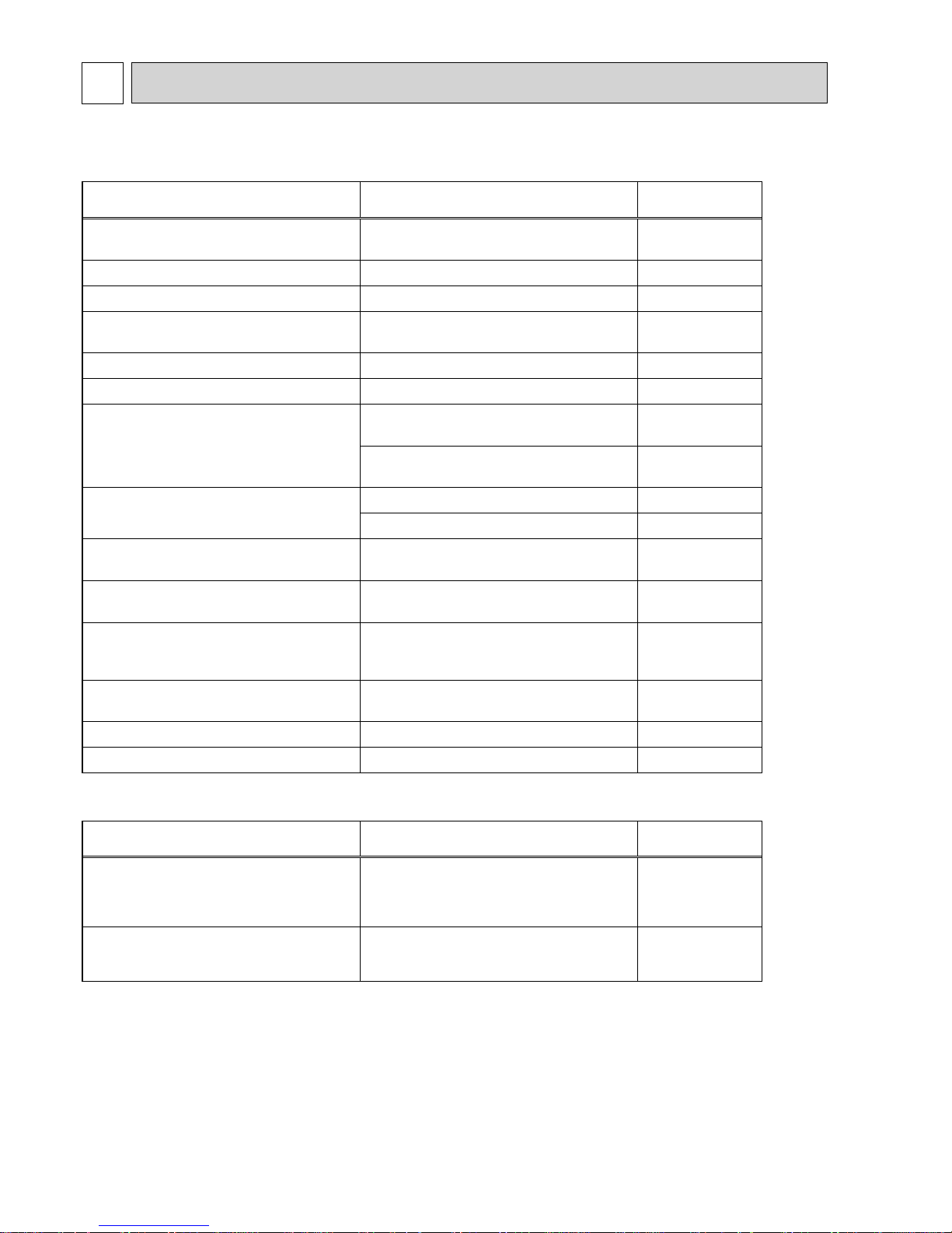
For information on service, please refer to the service manual as follows.
1-1. Indoor Unit
Model name Service Ref. Service
Manual No.
SLZ-KA25/35/50VA
SLZ-KA25/35/50VAL
SLZ-KA25/35/50VA
(1)
.TH
SLZ-KA25/35/50VAL
(1)
.TH
OC320
SEZ-KA35/50/60/71VA SEZ-KA35/50/60/71VA.TH OC321
SEZ-KC25VA SEZ-KC25VA.W MEE04K350
SEZ-KD25/35/50/60/71VA
SEZ-KD25/35/50/60/71VAL
SEZ-KD25/35/50/60/71VA.TH
SEZ-KD25/35/50/60/71VAL.TH
HWE07110
MFZ-KA25/35/50VA-E1 MFZ-KA25/35/50VA-E1 OB409
MFZ-KA25/35/50VA-A1 MFZ-KA25/35/50VA-A1 OB410
PLA-RP35/50/60/71BA
PLA-RP35/50/60/71BA
(1)
.UK
PLA-RP71BA2.UK
OCH412
OCB412
PLA-RP35/50/60/71BA
(1)
OCH416
OCB416
PLA-RP35/50/60/71AA
PLA-RP35/50/60/71AA.UK OC335
PLA-RP35/50/60/71AA OC327
PCA-RP50/60/71KA PCA-RP50/60/71KA
OCH454
OCB454
PCA-RP50/60/71GA
PCA-RP50GA2
PCA-RP50/60/71GA (#1)
PCA-RP50GA2 (#1)
OC328
PEAD-RP35/50/60/71JA(L)
PEAD-RP35/50/60/71JA(L).UK
PEAD-RP35/50/60/71JA(L)R1.UK
HWE08130
BWE08240
BWE09220
PEAD-RP50/60/71EA
PEAD-RP35EA2
PEAD-RP50/60/71EA.UK
PEAD-RP35EA2.UK
HWE05210
PEAD-RP60/71GA PEAD-RP60/71GA.UK HWE05060
PEA-RP71EA PEA-RP71EA.TH-A OC326
1-2. Outdoor Unit
Model name Service Ref. Service
Manual No.
SUZ-KA25/35/50/60/71VA
SUZ-KA25/35VAH
SUZ-KA25/35VA(R1).TH
SUZ-KA25/35VAH
(R1)
.TH
SUZ-KA50/60/71VA
(1)
.TH
SUZ-KA50/60VAR2.TH
OC322
SUZ-KA25/35/50/60/71VA
SUZ-KA25/35VA(R1).TH-A
SUZ-KA50/60/71VA
(1)
.TH-A
SUZ-KA50/60VAR2.TH-A
OC323
Page 3
3
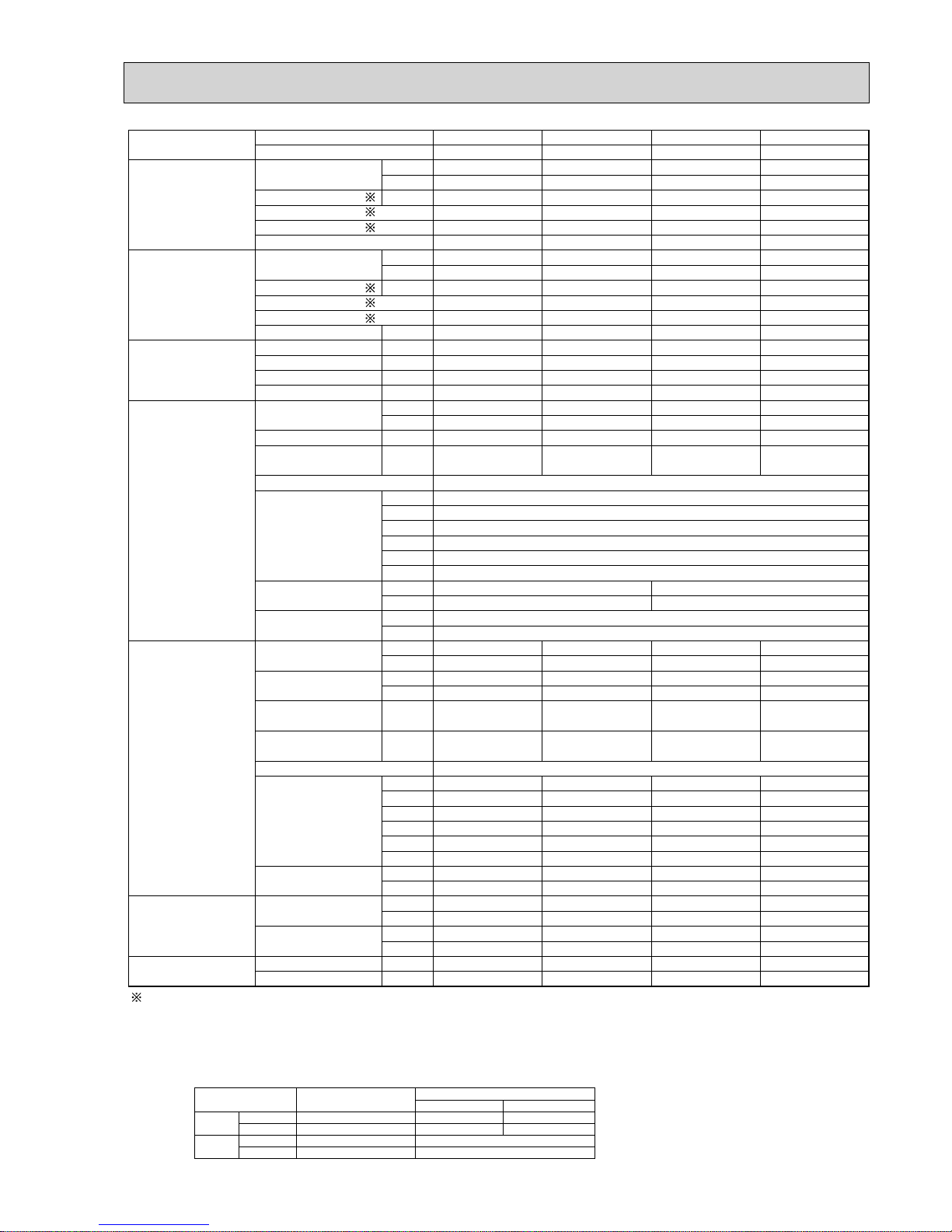
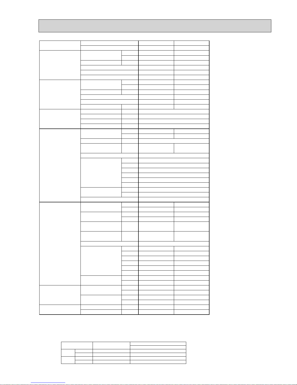
SPECIFICATIONS2
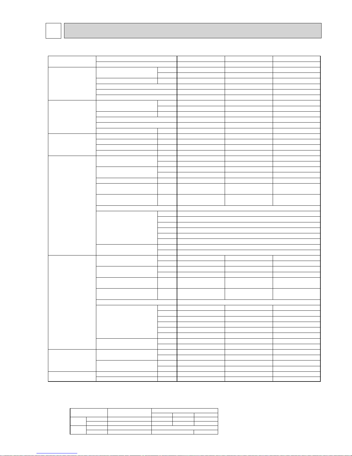
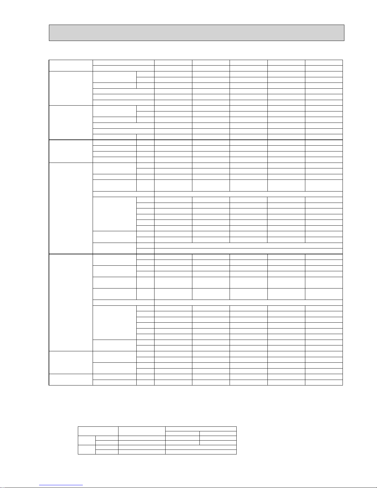
2-1. FLOOR STANDING TYPE
Model name
Indoor unit
MFZ-KA25VA MFZ-KA35VA MFZ-KA50VA
Outdoor unit
SUZ-KA25VA(H) SUZ-KA35VA(H) SUZ-KA50VA
Cooling
Capacity
Btu/h 8,500 11,900 16,400
kW 2.5(0.9-3.4) 3.5(0.9-3.9) 4.8(0.9-5.4)
Total input
kW 0.58 1.09 1.55
EER
4.31 3.21 3.1
Energy label class
AAB
SHF
0.66 0.65 0.63
Heating
Capacity
Btu/h 11,600 13,600 20,500
kW 3.4(0.9-5.1) 4.0(0.9-6.2) 6.0(0.9-7.9)
Total input
kW 0.835 1.10 1.86
COP
4.07 3.64 3.23
Energy label class
AAC
Booster heater
kW — — —
Power supply
Phase
: 111
Cycle
Hz 50 50 50
Voltage
V 230 230 230
Breaker size
A10 10 20
Indoor unit
Air flow at cooling
CMM 4.8 - 5.8 - 7.1 - 8.7 5.0 - 6.1 - 7.4 - 9.1 7.1 - 7.9 - 9.2 - 10.7
(Low-Medium-High-Super High)
CFM 170 - 205 - 250 - 310 180 - 215 - 260 - 320 250 - 280 - 325 - 380
Air flow at heating
CMM 5.0 - 6.2 - 7.6 - 9.1 5.2 - 6.2 - 7.8 - 9.5 7.4 - 8.8 - 9.8 - 11.8
(Low-Medium-High-Super High)
CFM 180 - 220 - 270 - 320 185 - 220 - 275 - 335 260 - 310 - 345 - 415
External static pressure
Pa 0 0 0
Sound level at cooling
dB(A) 22 - 27 - 32 - 37 23 - 28 - 33 - 38 32 - 35 - 39 - 43
(Low-Medium-High-Super High)
Sound level at heating
dB(A) 22 - 27 - 32 - 37 25 - 28 - 33 - 38 32 - 35 - 39 - 44
(Low-Medium-High-Super High)
External finish (Panel)
White Munsell 1.0Y 9.2/0.2
Dimension
W : mm 700
Unit (Panel)
D : mm 200
H : mm 600
W : inch 27 - 5/8
D : inch 7 - 7/8
H : inch 23 - 5/8
Weight
kg 14
Unit (Panel)
lbs 31
Outdoor unit
Air flow at cooling
CMM 34.3 33.4 27.5 - 49
(Low - High)
CFM 1,210 1,180 970 - 1,730
Air flow at heating
CMM 32.3 33.4 36.8 - 49
(Low - High)
CFM 1,140 1,180 1,300 - 1,730
Sound level at cooling
dB(A) 46 47 51 - 53
(Low - High)
Sound level at heating
dB(A) 46 48 53 - 55
(Low - High)
External finish
Ivory Munsell 3.0Y 7.8/1.1
Dimension
W : mm 800 800 840
D : mm 285 285 330
H : mm 550 550 850
W : inch 31 - 1/2 31 - 1/2 33 - 1/16
D : inch 11 - 1/4 11 - 1/4 13
H : inch 21 - 5/8 21 - 5/8 33 - 7/16
Weight kg 30 33 53
lbs 66 73 117
Refrigerant pipe size Gas side O.D. mm 9.52 9.52 12.7
inch 3/8 3/8 1/2
Liquid side . mm 6.35 6.35 6.35
inch 1/4 1/4 1/4
Refrigerant pipe length
Height difference
m
Max. 12
Max. 12 Max. 30
Length
m
Max. 20 Max. 20 Max. 30
NOTE: 1. Rating conditions (ISO T1)
Cooling Indoor : D.B. 27 (80°F) W.B. 19 (66°F) Outdoor : D.B. 35 (95°F) W.B. 24 (75°F)
Heating Indoor: D.B. 20 (68°F) Outdoor : D.B. 7 (45°F) W.B. 6 (43°F)
Refrigerant piping length (one way) : 5m (16ft.)
2. Guaranteed operating range
Indoor Outdoor
Cooling
Upper limit
32°C D.B. , 23°C W.B.
46°C D.B. 43°C D.B.
KA25, KA35VA
KA50
KA25,KA35VAH
Lower limit
21°C D.B. , 15°C W.B. -15°C D.B.-10°C D.B.
46°C D.B.
-10°C D.B.
Heating
Upper limit
27°C D.B.
24°C D.B. , 18°C W.B.
Lower limit
20°C D.B.
-10°C D.B. ,-11°C W.B.
-20°C D.B. ,-21°C W.B.
4. Above data are based on the indicated voltage.
Indoor unit Single phase, 230V 50Hz
Single phase, 230V 50Hz
Outdoor unit
3. Guaranteed voltage
198~264V, 50Hz
Page 4
4
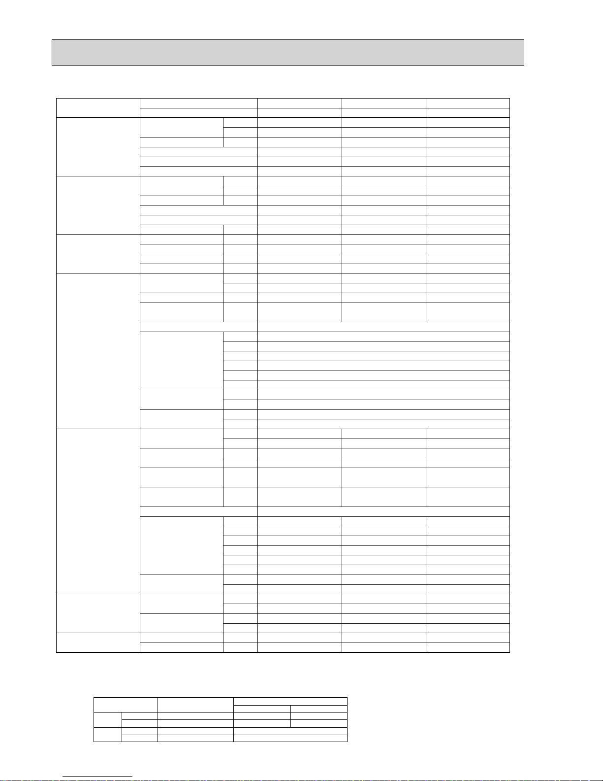
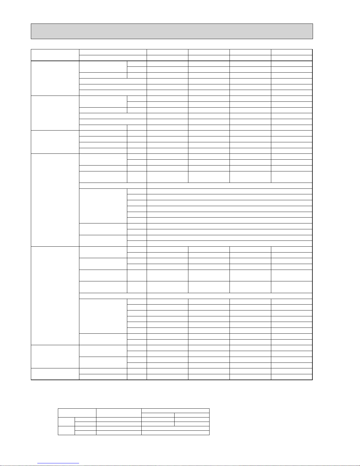
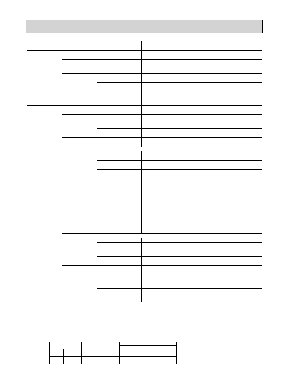
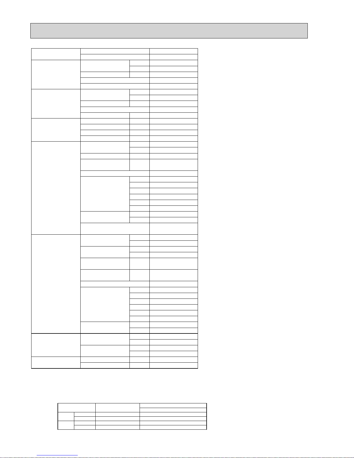
2-2. CEILING CASSETTE TYPE
Model name
Indoor unit
SLZ-KA25VA(L) SLZ-KA35VA(L) SLZ-KA50VA(L)
Outdoor unit
SUZ-KA25VA SUZ-KA35VA SUZ-KA50VA
Cooling
Capacity
Btu/h 8,500 11,900 15,700
kW 2.5(0.9 - 3.2) 3.5(1.0 - 3.9) 4.6(1.1 - 5.2)
Total input
kW 0.69 1.06 1.63
EER
3.62 3.30 2.82
Energy label class
AAC
SHF
0.86 0.77 0.68
Heating
Capacity
Btu/h 10,200 13,600 17,100
kW 3.0(0.9 - 4.5) 4.0(0.9 - 5.0) 5.0(0.9 - 6.5)
Total input
kW 0.83 1.10 1.55
COP
3.61 3.64 3.23
Energy label class
AAC
Booster heater
kW
———
Power supply
Phase
: 111
Cycle
Hz 50 50 50
Voltage
V 230 230 230
Breaker size
A10 10 20
Indoor unit
Air flow
CMM 8 - 9 - 10 8 - 9 - 11 8 - 9 - 11
(Low - Medium - High)
CFM 280 - 320 - 355 280 - 320 - 390 280 - 320 - 390
External static pressure
Pa 0 0 0
Sound level
dB(A) 28 - 31 - 37 29 - 33 - 38 30 - 34 - 39
(Low - Medium - High)
External finish (Panel)
White Munsell 6.4Y 8.9/0.4
Dimension
W : mm 570(650)
Unit(Panel)
D : mm 570(650)
H : mm 208(20)
W : inch 22 - 7/16(25 - 9/16)
D : inch 22 - 7/16(25 - 9/16)
H : inch 8-3/16(13/16)
Weight
kg 16.5(3)
Unit (Panel)
lbs 36(7)
Field drain pipe O.D.
mm 32
inch 1 - 1/4
Outdoor unit
Air flow at cooling
CMM 34.3 33.4 27.5 - 49
(Low - High)
CFM 1,210 1,180 970 - 1,730
Air flow at heating
CMM 32.3 33.4 36.8 - 49
(Low - High)
CFM 1,140 1,180 1,300 - 1,730
Sound level at cooling
dB(A) 46 47 51 - 53
(Low - High)
Sound level at heating
dB(A) 46 48 53 - 55
(Low - High)
External finish
Ivory Munsell 3.0Y 7.8/1.1
Dimension
W : mm 800 800 840
D : mm 285 285 330
H : mm 550 550 850
W : inch 31 - 1/2 31 - 1/2 33 - 1/16
D : inch 11 - 1/4 11 - 1/4 13
H : inch 21 - 5/8 21 - 5/8 33 - 7/16
Weight
kg 30 33 53
lbs 66 76 117
Refrigerant pipe size
Gas side O.D.
mm 9.52 9.52 12.7
inch 3/8 3/8 1/2
Liquid side O.D.
mm 6.35 6.35 6.35
inch 1/4 1/4 1/4
Refrigerant pipe length
Height difference
m Max. 12 Max. 12 Max. 30
Length
m Max. 20 Max. 20 Max. 30
NOTE: 1. Rating conditions (ISO T1)
Cooling Indoor : D.B. 27 (80°F) W.B. 19 (66°F) Outdoor : D.B. 35 (95°F) W.B. 24 (75°F)
Heating Indoor: D.B. 20 (68°F) Outdoor : D.B. 7 (45°F) W.B. 6 (43°F)
Refrigerant piping length (one way) : 5m (16ft.)
2. Guaranteed operating range
Indoor Outdoor
Cooling
Upper limit
32°C D.B. , 23°C W.B.
46°C D.B. 43°C D.B.
KA25, KA35VA
KA50
Lower limit
21°C D.B. , 15°C W.B. -15°C D.B.-10°C D.B.
Heating
Upper limit
27°C D.B.
24°C D.B. , 18°C W.B.
Lower limit
20°C D.B.
-10°C D.B. ,-11°C W.B.
4. Above data are based on the indicated voltage.
Indoor unit Single phase, 230V 50Hz
Single phase, 230V 50Hz
Outdoor unit
3. Guaranteed voltage
198~264V, 50Hz
Page 5
5
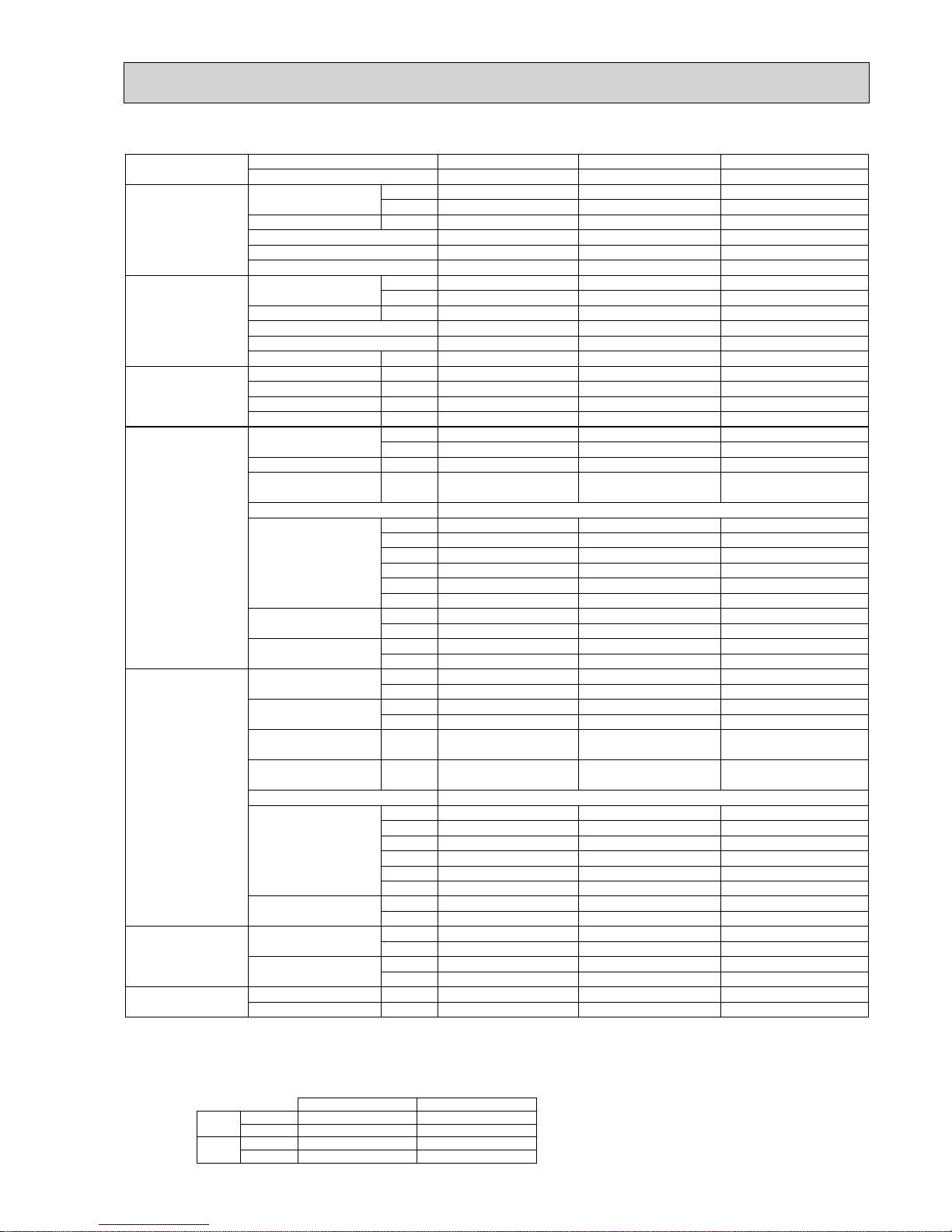
Model name Indoor unit PLA-RP35BA PLA-RP50BA PLA-RP60BA PLA-RP71BA(2)
Outdoor unit SUZ-KA35VA SUZ-KA50VA SUZ-KA60VA SUZ-KA71VA
Cooling Capacity Btu/h 11,900 17,100 19,400 24,200
kW 3.5(1.0 - 3.9) 5.0(1.1 - 5.6) 5.7(1.1 - 6.3) 7.1(0.9 - 8.1)
Total input kW 1.09 1.78 1.94 2.53(2.47)
EER 3.21 2.81 2.94 2.81(2.87)
Energy label class A C C C (
—)
SHF 0.84 0.81 0.76 0.73
Heating Capacity Btu/h 14,000 20,500 23,500 27,300
kW 4.1(0.9 - 5.0) 6.0(0.9 - 7.2) 6.9(0.9 - 8.0) 8.0(0.9 - 10.2)
Total input kW 1.11 1.82 2.11 2.49(2.45)
COP 3.69 3.30 3.27 3.21(3.27)
Energy label class A C C C (
—)
Booster heater kW
————
Power supply Phase : 1111
Cycle Hz50505050
Voltage V 230 230 230 230
Breaker size A 10 20 20 20
Indoor unit Air flow CMM 11 - 12 - 13 - 15 12 - 14 - 16 - 18 12 - 14 - 16 - 18 14 - 16 - 18 - 21
(Low-Medium2-Medium1-High)
CFM
390 - 425 - 460 - 530 425 - 495 - 565 - 635 425 - 495 - 565 - 635 495 - 565 - 635 - 740
External static pressure Pa 0 0 0 0
Sound level dB(A) 27 - 28 - 29 - 31 28 - 29 - 31 - 32 28 - 29 - 31 - 32 28 - 30 - 32 - 34
(Low-Medium2-Medium1-High)
External finish (Panel) White Munsell 6.4Y 8.9/0.4
Dimension W : mm 840 (950)
Unit (Panel) D : mm 840 (950)
H : mm 258 (35)
W : inch 33 - 1/16 (37 - 3/8)
D : inch 33 - 1/16 (37 - 3/8)
H : inch 10 - 3/16 (1 - 3/8)
Weight kg 23 (6)
Unit (Panel) lbs 51 (13)
22 (6)
49 (13)
Field drain pipe O.D. mm 32
inch 1 - 1/4
Outdoor unit Air flow at cooling CMM 33.4 27.5 - 49 27.5 - 49 27.5 - 49
(Low - High) CFM 1,180 970 - 1,730 970 - 1,730 970 - 1,730
Air flow at heating CMM 33.4 36.8 - 49 36.8 - 49 36.8 - 49
(Low - High) CFM 1,180 1,300 - 1,730 1,300 - 1,730 1,300 - 1,730
Sound level at cooling dB(A) 47 51 - 53 51 - 53 51 - 53
(Low - High)
Sound level at heating dB(A) 48 53 - 55 53 - 55 53 - 55
(Low - High)
External finish Ivory Munsell 3.0Y 7.8/1.1
Dimension W : mm 800 840 840 840
D : mm 285 330 330 330
H : mm 550 850 850 850
W : inch 31 - 1/2 33 - 1/16 33 - 1/16 33 - 1/16
D : inch 11 - 1/4 13 13 13
H : inch 21 - 5/8 33 - 7/16 33 - 7/16 33 - 7/16
Weight kg 33 53 53 58
lbs 76 117 117 128
Refrigerant pipe size Gas side O.D. mm 9.52 12.7 15.88 15.88
inch 3/8 1/2 5/8 5/8
Liquid side O.D. mm 6.35 6.35 6.35 9.52
inch 1/4 1/4 1/4 3/8
Refrigerant pipe length Height difference m Max. 12 Max. 30 Max. 30 Max. 30
Length m Max. 20 Max. 30 Max. 30 Max. 30
The values in the parentheses indicate the specification values for PLA-RP71BA2.
NOTE: 1. Rating conditions (ISO T1)
Cooling Indoor : D.B. 27 (80°F) W.B. 19 (66°F) Outdoor : D.B. 35 (95°F) W.B. 24 (75°F)
Heating Indoor: D.B. 20 (68°F) Outdoor : D.B. 7 (45°F) W.B. 6 (43°F)
Refrigerant piping length (one way) : 5m (16ft.)
2. Guaranteed operating range
Indoor Outdoor
Cooling
Upper limit
32°C D.B. , 23°C W.B.
46°C D.B. 43°C D.B.
KA35VA
KA50, KA60, KA71
Lower limit
21°C D.B. , 15°C W.B. -15°C D.B.-10°C D.B.
Heating
Upper limit
27°C D.B.
24°C D.B. , 18°C W.B.
Lower limit
20°C D.B.
-10°C D.B. ,-11°C W.B.
4. Above data are based on the indicated voltage.
Indoor unit Single phase, 230V 50Hz
Single phase, 230V 50Hz
Outdoor unit
3. Guaranteed voltage
198~264V, 50Hz
Page 6
6
Model name Indoor unit PLA-RP35AA PLA-RP50AA PLA-RP60AA PLA-RP71AA
Outdoor unit SUZ-KA35VA SUZ-KA50VA SUZ-KA60VA SUZ-KA71VA
Cooling Capacity Btu/h 11,900 17,100 19,400 24,200
kW 3.5(1.0 - 3.9) 5.0(1.1 - 5.6) 5.7(1.1 - 6.3) 7.1(0.9 - 8.1)
Total input kW 1.09 1.78 1.94 2.53
EER 3.21 2.81 2.94 2.81
Energy label class A C C C
SHF 0.88 0.86 0.83 0.77
Heating Capacity Btu/h 14,000 20,500 23,500 27,300
kW 4.1(0.9 - 5.0) 6.0(0.9 - 7.2) 6.9(0.9 - 8.0) 8.0(0.9 - 10.2)
Total input kW 1.11 1.76 2.11 2.49
COP 3.69 3.41 3.27 3.21
Energy label class A B C C
Booster heater kW
————
Power supply Phase : 1111
Cycle Hz50505050
Voltage V 230 230 230 130
Breaker size A 10 20 20 20
Indoor unit Air flow CMM 11 - 12 - 13 - 14 14 - 15 - 16 - 18 14 - 15 - 16 - 18 15 - 16 - 18 - 20
(Low-Medium2-Medium1-High)
CFM
390 - 425 - 460 - 495 495 - 530 - 565 - 635 495 - 530 - 565 - 635 530 - 565 - 635 - 705
External static pressure Pa 0 0 0 0
Sound level dB(A) 27 - 28 - 29 - 31 28 - 29 - 31 - 33 28 - 29 - 31 - 33 28 - 30 - 32 - 34
(Low-Medium2-Medium1-High)
External finish (Panel) White Munsell 0.70Y 8.59/0.97
Dimension W : mm 840 (950)
Unit (Panel) D : mm 840 (950)
H : mm 258 (30)
W : inch 33 - 1/16 (37 - 3/8)
D : inch 33 - 1/16 (37 - 3/8)
H : inch 10 - 3/16 (1 - 3/16)
Weight kg 24 (5)
Unit (Panel) lbs 53 (11)
Field drain pipe O.D. mm 32
inch 1 - 1/4
Outdoor unit Air flow at cooling CMM 33.4 27.5 - 49 27.5 - 49 27.5 - 49
(Low - High) CFM 1,180 970 - 1,730 970 - 1,730 970 - 1,730
Air flow at heating CMM 33.4 36.8 - 49 36.8 - 49 36.8 - 49
(Low - High) CFM 1,180 1,300 - 1,730 1,300 - 1,730 1,300 - 1,730
Sound level at cooling dB(A) 47 51 - 53 51 - 53 51 - 53
(Low - High)
Sound level at heating dB(A) 48 53 - 55 53 - 55 53 - 55
(Low - High)
External finish Ivory Munsell 3.0Y 7.8/1.1
Dimension W : mm 800 840 840 840
D : mm 285 330 330 330
H : mm 550 850 850 850
W : inch 31 - 1/2 33 - 1/16 33 - 1/16 33 - 1/16
D : inch 11 - 1/4 13 13 13
H : inch 21 - 5/8 33 - 7/16 33 - 7/16 33 - 7/16
Weight kg 33 53 53 58
lbs 76 117 117 128
Refrigerant pipe size Gas side O.D. mm 9.52 12.7 15.88 15.88
inch 3/8 1/2 5/8 5/8
Liquid side O.D. mm 6.35 6.35 6.35 9.52
inch 1/4 1/4 1/4 3/8
Refrigerant pipe length Height difference m Max. 12 Max. 30 Max. 30 Max. 30
Length m Max. 20 Max. 30 Max. 30 Max. 30
NOTE: 1. Rating conditions (ISO T1)
Cooling Indoor : D.B. 27 (80°F) W.B. 19 (66°F) Outdoor : D.B. 35 (95°F) W.B. 24 (75°F)
Heating Indoor: D.B. 20 (68°F) Outdoor : D.B. 7 (45°F) W.B. 6 (43°F)
Refrigerant piping length (one way) : 5m (16ft.)
2. Guaranteed operating range
Indoor Outdoor
Cooling
Upper limit
32°C D.B. , 23°C W.B.
46°C D.B. 43°C D.B.
KA35VA
KA50, KA60, KA71
Lower limit
21°C D.B. , 15°C W.B. -15°C D.B.-10°C D.B.
Heating
Upper limit
27°C D.B.
24°C D.B. , 18°C W.B.
Lower limit
20°C D.B.
-10°C D.B. ,-11°C W.B.
4. Above data are based on the indicated voltage.
Indoor unit Single phase, 230V 50Hz
Single phase, 230V 50Hz
Outdoor unit
3. Guaranteed voltage
198~264V, 50Hz
Page 7
7
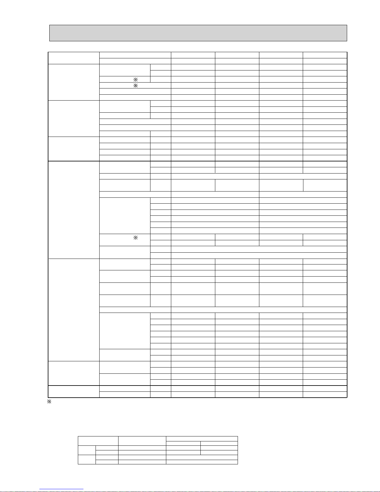
2-3. CEILING-SUSPENDED TYPE
Model name Indoor unit
PCA-RP50KA
SUZ-KA50VA
17,100
5.0(1.1-5.6)
1.660
3.01
B
0.79
18,800
5.5(0.9-6.6)
1.710
3.22
C
—
1
50
230
20
10 - 11 - 13 - 15
355 - 390 - 460 - 530
0
32 - 34 - 37 - 40
960
680
230
37 - 13/16
26 - 3/4
9 - 1/16
25
55
26
1
27.5 - 49
970 - 1,730
36.8 - 49
1,300 - 1,730
51 - 53
53 - 55
840
330
850
33 - 1/16
13
33 - 7/16
53
117
12.7
1/2
6.35
1/4
Max. 30
Max. 30
PCA-RP71KA
SUZ-KA71VA
24,200
7.1(0.9-8.1)
2.210
3.21
A
0.76
27,000
7.9(0.9-10.2)
2.320
3.41
B
—
1
50
230
20
16 - 17 - 18 - 20
565 - 600 - 635 - 705
0
35 - 37 - 39 - 41
1,280
680
230
50 - 3/8
26 - 3/4
9 - 1/16
32
71
26
1
27.5 - 49
970 - 1,730
36.8 - 49
1,300 - 1,730
51 - 53
53 - 55
840
330
850
33 - 1/16
13
33 - 7/16
58
128
15.88
5/8
9.52
3/8
Max. 30
Max. 30
Outdoor unit
Cooling Capacity Btu/h
kW
Total input
kW
EER
Energy label class
SHF
Heating Capacity Btu/h
kW
Total input kW
COP
Energy label class
Booster heater kW
Power supply Phase :
Cycle Hz
Voltage V
Breaker size A
Indoor unit Air flow CMM
(Low-Medium2-Medium1-High)
CFM
External static pressure Pa
Sound level dB(A)
(Low-Medium2-Medium1-High)
External finish White Munsell 6.4Y 8.9/0.4
Dimension W : mm
D : mm
H : mm
W : inch
D : inch
H : inch
Weight
kg
lbs
Field drain pipe O.D. mm
inch
Outdoor unit Air flow at cooling CMM
(Low - High)
CFM
Air flow at heating CMM
(Low - High)
CFM
Sound level at cooling dB(A)
(Low - High)
Sound level at heating dB(A)
(Low - High)
External finish
Ivory Munsell 3.0Y 7.8/1.1
Dimension W : mm
D : mm
H : mm
W : inch
D : inch
H : inch
Weight
kg
lbs
Refrigerant pipe size Gas side O.D. mm
inch
Liquid side O.D. mm
inch
Refrigerant pipe length
Height difference
m
Length
m
PCA-RP60KA
SUZ-KA60VA
19,400
5.7(1.1-6.3)
1.770
3.22
A
0.81
23,500
6.9(0.9-8.0)
2.020
3.42
B
—
1
50
230
20
15 - 16 - 17 - 19
530 - 565 - 600 - 670
0
33 - 35 - 37 - 40
1,280
680
230
50 - 3/8
26 - 34
9 - 1/16
32
71
26
1
27.5 - 49
970 - 1,730
36.8 - 49
1,300 - 1,730
51 - 53
53 - 55
840
330
850
33 - 1/16
13
33 - 7/16
53
117
15.88
5/8
6.35
1/4
Max. 30
Max. 30
NOTE: 1. Rating conditions (ISO T1)
Cooling Indoor : D.B. 27 (80°F) W.B. 19 (66°F) Outdoor : D.B. 35 (95°F) W.B. 24 (75°F)
Heating Indoor: D.B. 20 (68°F) Outdoor : D.B. 7 (45°F) W.B. 6 (43°F)
Refrigerant piping length (one way) : 5m (16ft.)
2. Guaranteed operating range
Indoor Outdoor
Cooling
Upper limit
D.B. 32°C, W.B. 23°C
D.B. 43°C
Lower limit
D.B. 21°C, W.B. 15°C D.B. -15°C
Heating
Upper limit
D.B. 27°C
D.B. 24°C, W.B. 18°C
Lower limit
D.B. 20°C
D.B. -10°C, W.B. -11°C
4. Above data are based on the indicated voltage.
Indoor unit Single phase, 230V 50Hz
Single phase, 230V 50Hz
Outdoor unit
3. Guaranteed voltage
198~264V, 50Hz
Page 8
8
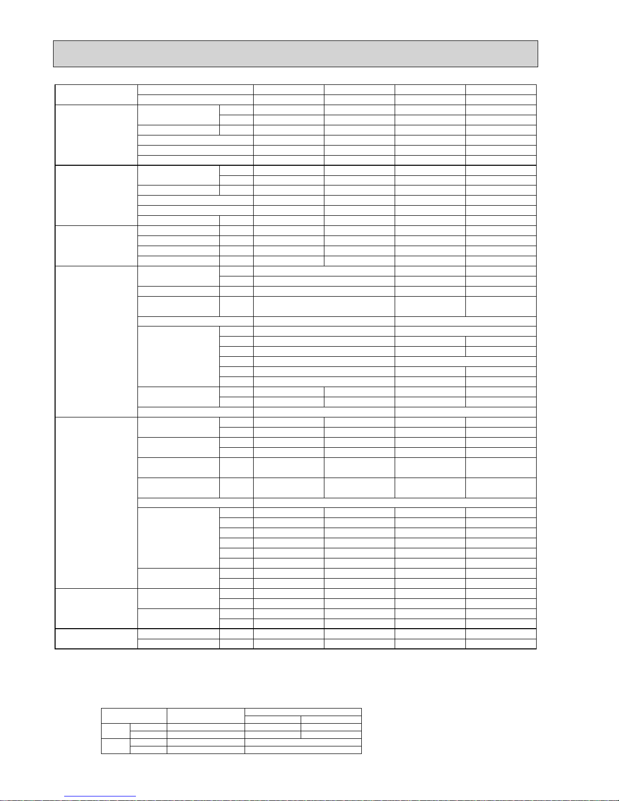
Model name Indoor unit PCA-RP50GA PCA-RP60GA PCA-RP71GA
Outdoor unit SUZ-KA50VA SUZ-KA60VA SUZ-KA71VA
Cooling Capacity Btu/h 16,000 18,800 24,200
kW 4.7(1.1 - 5.4) 5.5(1.1 - 6.3) 7.1(0.9 - 8.1)
Total input
kW 1.80 1.92 2.53
EER 2.61 2.86 2.81
Energy label class
DCC
SHF 0.70 0.79 0.71
Heating Capacity Btu/h 18,800 23,500 27,300
kW 5.5(0.9 - 6.6) 6.9(0.9 - 8.0) 8.0(0.9 - 10.2)
Total input kW 1.92 2.05 2.49
COP 2.86 3.37 3.21
Energy label class
DCC
Booster heater kW
———
Power supply Phase : 1
Cycle Hz 50
Voltage V 230
Breaker size A 20
Indoor unit Air flow CMM 10 - 11 - 12 - 13 14 - 15 - 16 - 18
(Low-Medium2-Medium1-High)
CFM
355 - 390 - 425 - 460
495 - 530 - 565 - 635
External static pressure Pa 0 0
Sound level dB(A) 37 - 38 - 40 - 42 37 - 39 - 41 - 43
(Low-Medium2-Medium1-High)
External finish White Munsell 0.70Y 8.59/0.97
Dimension W : mm 1000 1310
D : mm 680
H : mm 210
W : inch 39 - 3/8 51 - 9/16
D : inch 26 - 3/4
H : inch 8 - 1/4
Weight
kg
27 34
lbs 60 75
Field
drain pipe O.D. mm 26
inch 1
Outdoor unit Air flow at cooling CMM 27.5 - 49 27.5 - 49 27.5 - 49
(Low - High)
CFM 970 - 1,730 970 - 1,730 970 - 1,730
Air flow at heating CMM 36.8 - 49 36.8 - 49
27.5 - 49
970 - 1,730
36.8 - 49 36.8 - 49
(Low - High)
CFM 1,300 - 1,730 1,300 - 1,730 1,300 - 1,730
Sound level at cooling dB(A) 51 - 53 51 - 53 51 - 53
(Low - High)
Sound level at heating dB(A) 53 - 55 53 - 55
51 - 53
53 - 55 53 - 55
(Low - High)
External finish
Ivory Munsell 3.0Y 7.8/1.1
Dimension W : mm 840 840 840
D : mm 330 330 330
H : mm 850 850 850
W : inch 33 - 1/16 33 - 1/16 33 - 1/16
D : inch 13 13 13
H : inch 33 - 7/16 33 - 7/16 33 - 7/16
Weight
kg
53 53 58
lbs 117 117 128
Refrigerant pipe size Gas side O.D. mm 12.7 15.88 15.88
inch 1/2 5/8 5/8
Liquid side O.D. mm 6.35 6.35 9.52
inch 1/4 1/4 3/8
Refrigerant pipe length
Height difference
m Max. 30 Max. 30 Max. 30
Length
m Max. 30 Max. 30 Max. 30
PCA-RP50GA2
SUZ
-
KA50VA
17,000
5.0(1.1 - 5.6)
1.78
2.81
C
0.81
20,500
6.0(0.9 - 7.2)
1.76
3.41
B
—
970 - 1,730
840
330
850
33 - 1/16
13
33 - 7/16
53
117
12.7
1/2
6.35
1/4
Max. 30
Max. 30
NOTE: 1. Rating conditions (ISO T1)
Cooling Indoor : D.B. 27 (80°F) W.B. 19 (66°F) Outdoor : D.B. 35 (95°F) W.B. 24 (75°F)
Heating Indoor: D.B. 20 (68°F) Outdoor : D.B. 7 (45°F) W.B. 6 (43°F)
Refrigerant piping length (one way) : 5m (16ft.)
2. Guaranteed operating range
Indoor Outdoor
Cooling
Upper limit
D.B. 32°C, W.B. 23°C
D.B. 43°C
Lower limit
D.B. 21°C, W.B. 15°C D.B. -15°C
Heating
Upper limit
D.B. 27°C
D.B. 24°C, W.B. 18°C
Lower limit
D.B. 20°C
D.B. -10°C, W.B. -11°C
4. Above data are based on the indicated voltage.
Indoor unit Single phase, 230V 50Hz
Single phase, 230V 50Hz
Outdoor unit
3. Guaranteed voltage
198~264V, 50Hz
Page 9
9
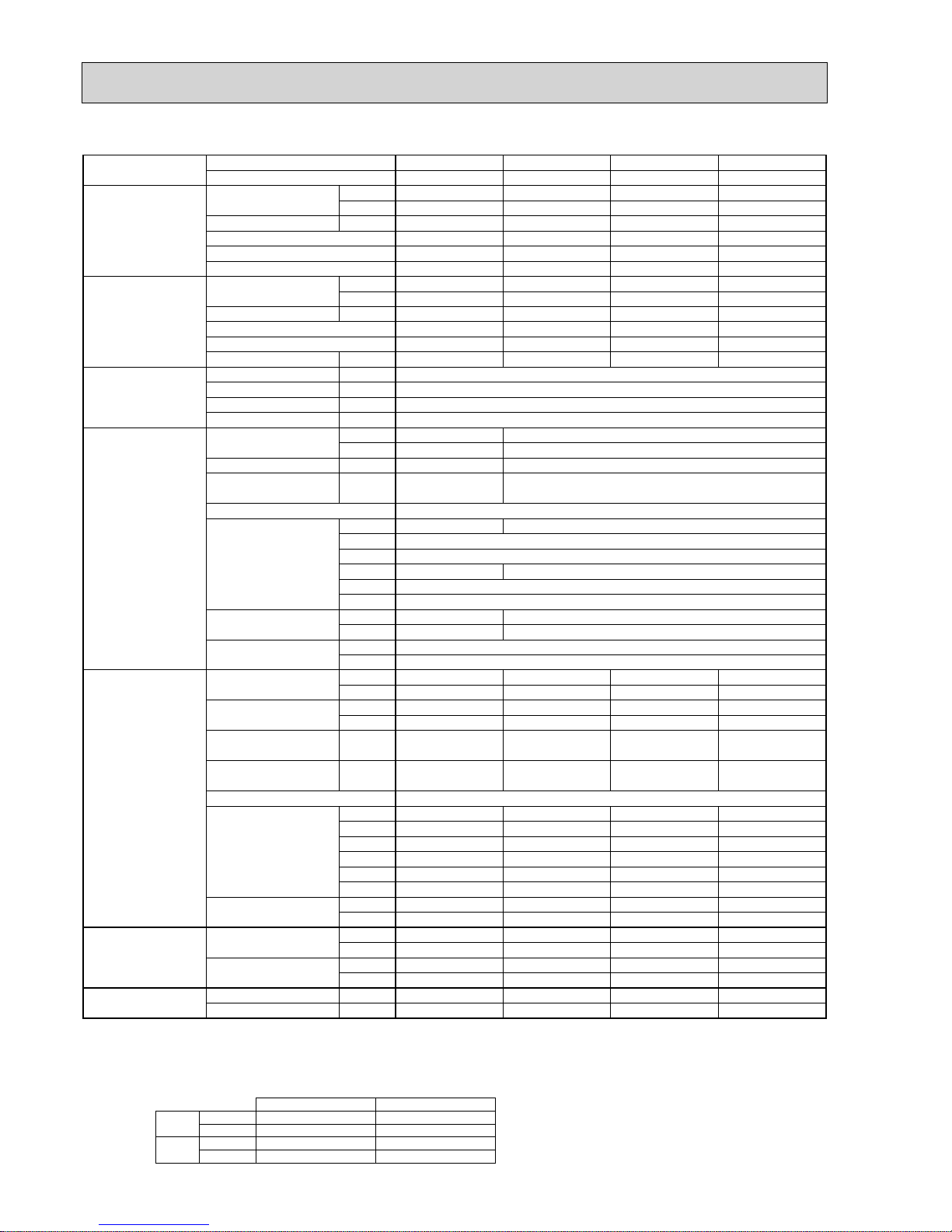
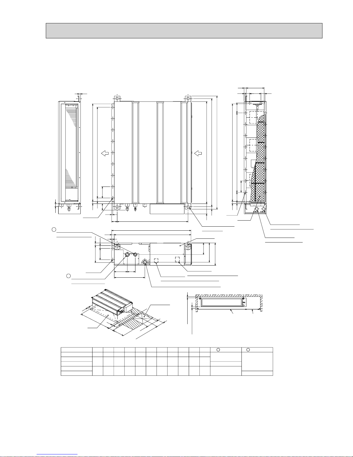
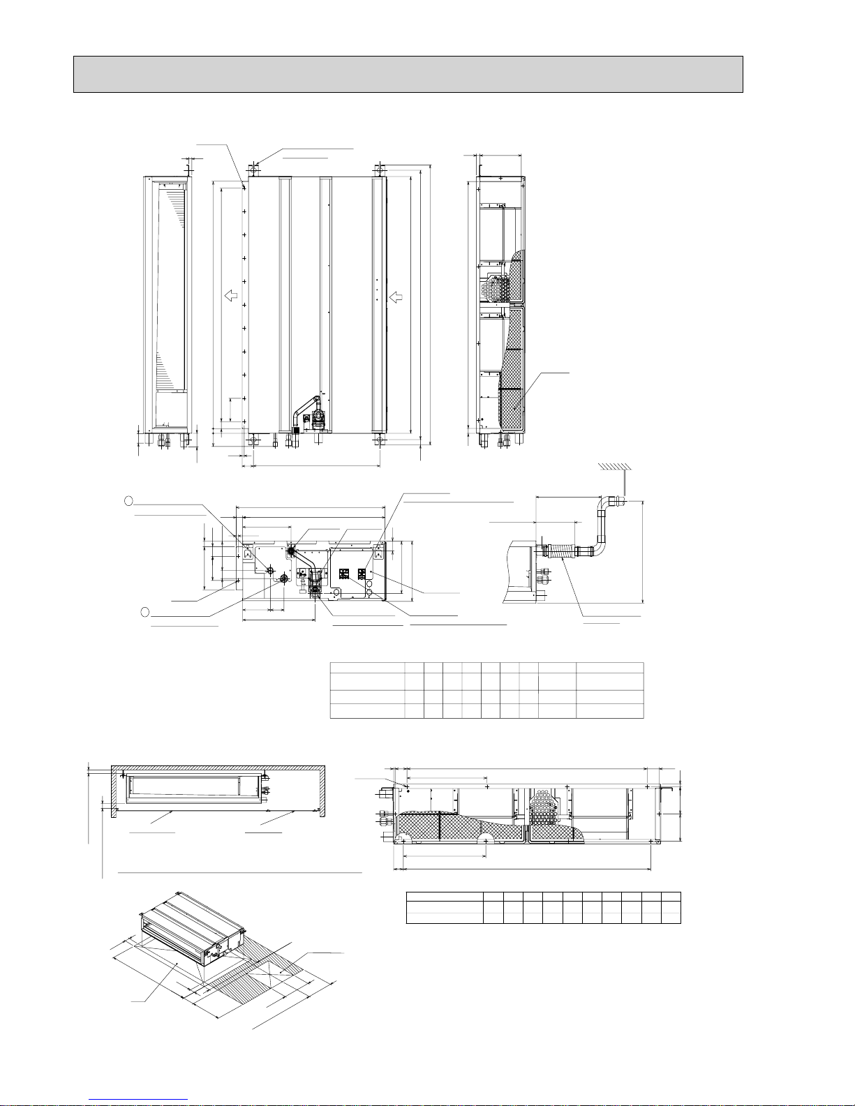
2-4. CEILING-CONCEALED TYPE
NOTE: 1. Rating conditions (ISO T1)
Cooling Indoor : D.B. 27 (80°F) W.B. 19 (66°F) Outdoor : D.B. 35 (95°F) W.B. 24 (75°F)
Heating Indoor: D.B. 20 (68°F) Outdoor : D.B. 7 (45°F) W.B. 6 (43°F)
Refrigerant piping length (one way) : 5m (16ft.)
2. Guaranteed operating range
Indoor Outdoor
Cooling
Upper limit
32°C D.B. , 23°C W.B.
46°C D.B.
-10°C D.B.
43°C D.B.
KA25, KA35VA KA50, KA60, KA71
Lower limit
21°C D.B. , 15°C W.B. -15°C D.B.
Heating
Upper limit
27°C D.B.
24°C D.B. , 18°C W.B.
Lower limit
20°C D.B.
-10°C D.B. ,-11°C W.B.
4. Above data are based on the indicated voltage.
Indoor unit Single phase, 230V 50Hz
Single phase, 230V 50Hz
Outdoor unit
3. Guaranteed voltage
198~264V, 50Hz
Model name Indoor unit SEZ-KD25VA(L) SEZ-KD35VA(L) SEZ-KD50VA(L) SEZ-KD60VA(L) SEZ-KD71VA(L)
Outdoor unit SUZ-KA25VA SUZ-KA35VA SUZ-KA50VA SUZ-KA60VA SUZ-KA71VA
Cooling Capacity Btu/h 8,500 11,900 17,100 18,800 24,200
kW 2.5(0.9 - 3.2
)
3.5(1.0 - 3.9
)
5.0(1.1 - 5.6
)
5.5(1.1 - 6.3
)
7.1(0.9 - 8.3
)
Total input kW 0.778 1.09 1.78 1.89 2.53
EER 3.21 3.21 2.81 2.91 2.81
Energy label class A A C C C
SHF 0.80 0.78 0.76 0.79 0.74
Heating Capacity Btu/h 10,200 13,600 20,500 23,900 27,600
kW 3.0(0.9 - 4.5
)
4.0(0.9 - 5.0
)
6.0(1.1 - 7.2
)
7.0(0.9 - 8.0
)
8.1(0.9 - 10.4
)
Total input kW 0.83 1.108 1.87 2.05 2.37
COP 3.61 3.61 3.21 3.41 3.42
Energy label class A A C B B
Booster heater kW
—————
Power supply Phase : 11111
Cycle Hz5050505050
Voltage V 230 230 230 230 230
Breaker size A 10 10 20 20 20
Indoor unit Air flow CMM 5.5 - 7.0 - 9.0 7.0 - 9.0 - 11.0 10.0 - 12.5 - 15.0 12.0 - 15.0 - 18.0 12.0 - 16.0 - 20.0
(
Low - Medium - High
)
(
Low - Medium - High
)
CFM 190 - 250 - 320 250 - 320 - 390 350 - 440 - 530 420 - 530 - 640 420 - 570 - 710
External static pressure
Pa 5 - 15 - 35 - 50 5 - 15 - 35 - 50 5 - 15 - 35 - 505 - 15 - 35 - 50 5 - 15 - 35 - 50
Sound level dB(A
)
23 - 26 -30 23 - 28 -33 30 - 34 -37 30 - 34 -38 30 - 35 -40
External finish Galvanized sheets
Dimension W : mm 700
D : mm 700
H : mm 200
W : inch 27 - 9/16
D : inch 27 - 9/16
H : inch 7 - 7/8
Weight kg 18
lbs 40
900
700
200
35 - 7/16
27 - 9/16
7 - 7/8
21
47
900
700
200
35 - 7/16
27 - 9/16
7 - 7/8
23
51
1100
700
200
43 - 5/16
27 - 9/16
7 - 7/8
27
60
1100
700
200
43 - 5/16
27 - 9/16
7 - 7/8
27
60
Field drain pipe O.D. 32
1 - 9/32
Outdoor unit Air flow at cooling CMM 34.3 33.4 27.5 - 49 27.5 - 49 27.5 - 49
(
Low - High
)
CFM 1,210 1,180 970 - 1,730 970 - 1,730 970 - 1,730
Air flow at heating CMM 32.3 33.4 36.8 - 49 36.8 - 49 36.8 - 49
(
Low - High
)
CFM 1,140 1,180 1,300 - 1,730 1.300 - 1,730 1,300 - 1,730
Sound level at cooling dB(A
)
46 47 51 - 53 51 - 53 51 - 53
(
Low - High
)
Sound level at heating dB(A
)
46 48 53 - 55 53 - 55 53 - 55
(
Low - High
)
External finish Ivory Munsell 3.0Y 7.8/1.1
Dimension W : mm 800 800 840 840 840
D : mm 285 285 330 330 330
H : mm 550 550 850 850 850
W : inch 31 - 1/2 31 - 1/2 33 - 1/16 33 - 1/16 33 - 1/16
D : inch 11 - 1/4 11 - 1/4 13 13 13
H : inch 21 - 5/8 21 - 5/8 33 - 7/16 33 - 7/16 33 - 7/16
Weight kg 30 33 53 53 58
lbs 66 76 117 117 128
Refrigerant pipe size Gas side O.D. mm
mm
9.52 9.52 12.7 15.88 15.88
inch
inch
3/8
3/8 1/2 5/8 5/8
Liquid side O.D. mm 6.35 6.35 6.35 6.35 9.52
inch 1/4 1/4 1/4 1/4 3/8
Refrigerant pipe length Height difference m Max. 12 Max. 12 Max. 30 Max. 30 Max. 30
Length m Max. 20 Max. 20 Max. 30 Max. 30 Max. 30
Page 10
10
Model name Indoor unit SEZ-KC25VA SEZ-KA35VA SEZ-KA50VA SEZ-KA60VA SEZ-KA71VA
Outdoor unit SUZ-KA25VA SUZ-KA35VA SUZ-KA50VA SUZ-KA60VA SUZ-KA71VA
Cooling Capacity Btu/h 8,500 11,900 17,100 18,800 24,200
kW 2.5(0.9 - 3.2
)
3.5(1.0 - 3.9
)
5.0(1.1 - 5.6
)
5.5(1.1 - 6.3
)
7.1(0.9 - 8.3
)
Total input kW 0.73 1.06 1.78 1.96 2.46
EER 3.42 3.30 2.81 2.81 2.89
Energy label class A A C C C
SHF 0.74 0.77 0.75 0.75 0.74
Heating Capacity Btu/h 10,200 13,600 20,100 23,500 27,600
kW 3.0(0.9 - 4.5
)
4.0(0.9 - 5.0
)
5.9(1.1 - 7.2
)
6.9(0.9 - 8.0)8.1(0.9 - 10.4
)
Total input kW 0.83 1.10 1.84 2.45 2.36
COP 3.61 3.64 3.21 2.82 3.43
Energy label class A A C D B
Booster heater kW
—————
Power supply Phase : 11111
Cycle Hz5050505050
Voltage V 230 230 230 230 230
Breaker size A 10 10 20 20 20
Indoor unit Air flow CMM 4.8 - 7.9 10 - 13 12 - 17 12 - 20 12 - 20
(
Low - High
)
CFM 170 - 280 355 - 460 425 - 600 425 - 705 425 - 705
External static pressure
Pa Std:5 Max:5 Std:30 Max:50 Std:30 Max:50 Std:30 Max:50 Std:30 Max:50
Sound level dB(A
)
25 - 36 30 - 35 31 - 39 32 - 43 32 - 43
(
Low - High
)
External finish Galvanized sheets
Dimension W : mm 790 1100
D : mm 550 700
H : mm 225 270
W : inch 31 - 1/8 43 - 5/16
D : inch 21 - 5/8 27 - 9/16
H : inch 8 - 7/8 10 - 5/8
Weight kg 19 33.5 35
lbs 42 74 77
Unit drain pipe R1(External thread
)
R1(External thread
)
Outdoor unit Air flow at cooling CMM 34.3 33.4 27.5 - 49 27.5 - 49 27.5 - 49
(
Low - High
)
CFM 1,210 1,180 970 - 1,730 970 - 1,730 970 - 1,730
Air flow at heating CMM 32.3 33.4 36.8 - 49 36.8 - 49 36.8 - 49
(
Low - High
)
CFM 1,140 1,180 1,300 - 1,730 1.300 - 1,730 1,300 - 1,730
Sound level at cooling dB(A
)
46 47 51 - 53 51 - 53 51 - 53
(
Low - High
)
Sound level at heating dB(A
)
46 48 53 - 55 53 - 55 53 - 55
(
Low - High
)
External finish Ivory Munsell 3.0Y 7.8/1.1
Dimension W : mm 800 800 840 840 840
D : mm 285 285 330 330 330
H : mm 550 550 850 850 850
W : inch 31 - 1/2 31 - 1/2 33 - 1/16 33 - 1/16 33 - 1/16
D : inch 11 - 1/4 11 - 1/4 13 13 13
H : inch 21 - 5/8 21 - 5/8 33 - 7/16 33 - 7/16 33 - 7/16
Weight kg 30 33 53 53 58
lbs 66 76 117 117 128
Refrigerant pipe size Gas side O.D. mm 9.52 9.52 12.7 15.88 15.88
inch 3/8 3/8 1/2 5/8 5/8
Liquid side O.D. mm 6.35 6.35 6.35 6.35 9.52
inch 1/4 1/4 1/4 1/4 3/8
Refrigerant pipe length Height difference m Max. 12 Max. 12 Max. 30 Max. 30 Max. 30
Length m Max. 20 Max. 20 Max. 30 Max. 30 Max. 30
NOTE: 1. Rating conditions (ISO T1)
Cooling Indoor : D.B. 27 (80°F) W.B. 19 (66°F) Outdoor : D.B. 35 (95°F) W.B. 24 (75°F)
Heating Indoor: D.B. 20 (68°F) Outdoor : D.B. 7 (45°F) W.B. 6 (43°F)
Refrigerant piping length (one way) : 5m (16ft.)
2. Guaranteed operating range
Indoor Outdoor
Cooling
Upper limit
32°C D.B. , 23°C W.B.
46°C D.B.
-10°C D.B.
43°C D.B.
KA25, KA35VA KA50, KA60, KA71
Lower limit
21°C D.B. , 15°C W.B. -15°C D.B.
Heating
Upper limit
27°C D.B.
24°C D.B. , 18°C W.B.
Lower limit
20°C D.B.
-10°C D.B. ,-11°C W.B.
4. Above data are based on the indicated voltage.
Indoor unit Single phase, 230V 50Hz
Single phase, 230V 50Hz
Outdoor unit
3. Guaranteed voltage
198~264V, 50Hz
Page 11
11
Model name Indoor unit PEAD-RP35JA(L) PEAD-RP50JA(L) PEAD-RP60JA(L) PEAD-RP71JA(L)
Outdoor unit SUZ-KA35VA
12,300
3.6 (1.0-3.9)
1.060 (1.040)
3.40 (3.46)
A
0.85
14,000
4.1 (0.9-5.0)
1.110
3.69
A
—
1
50
230
16
10 - 12 - 14
353 - 424 - 494
23 - 27 - 30
SUZ-KA50VA
16,700
4.9 (1.1-5.6)
1.520 (1.500)
3.22 (3.27)
A
0.85
20,100
5.9 (0.9-7.2)
1.620
3.64
A
—
1
50
230
20
12 - 14.5 - 17
424 - 512 - 600
26 - 31 - 35
SUZ-KA60VA
19,400
5.7 (1.1-6.3)
1.680 (1.660)
3.39 (3.43)
A
0.86
23,900
7.0 (0.9-8.0)
1.940
3.61
A
—
1
50
230
20
14.5 - 18 - 21
512 - 636 - 742
25 - 29 - 33
SUZ-KA71VA
24,200
7.1 (0.9-8.1)
2.210 (2.190)
3.21 (3.24)
A
0.83
27,300
8.0 (0.9-10.2)
2.090
3.83
A
—
1
50
230
20
17.5 - 21 - 25
618 - 742 - 883
26 - 30 - 34
Cooling Capacity Btu/h
kW
Total input kW
EER
Energy label class
SHF
Heating Capacity Btu/h
kW
Total input kW
COP
Energy label class
Booster heater kW
Power supply Phase :
Cycle Hz
Voltage V
Breaker size A
Indoor unit Air flow CMM
(
Low - High
)
CFM
External static pressure Pa
Sound level dB(A
)
(
Low - High
)
External finish
900
732
250
35 - 7/16
28 - 7/8
9 - 7/8
Galvanized sheets
Dimension W : mm 1,100
732
250
43 - 5/16
28 - 7/8
9 - 7/8
D : mm
H : mm
W : inch
D : inch
H : inch
Weight
kg 26 (25)
58 (56)
28 (27)
62 (60)
33 (32)
73 (71)
33 (32)
lbs
mm
inch
73 (71)
Field drain pipe O.D.
Outdoor unit Air flow at cooling CMM 33.4 27.5 - 49 27.5 - 49 27.5 - 49
(
Low - High
)
CFM 1,180 970 - 1,730 970 - 1,730 970 - 1,730
Air flow at heating CMM 33.4 36.8 - 49 36.8 - 49 36.8 - 49
(
Low - High
)
CFM 1,180 1,300 - 1,730 1,300 - 1,730 1,300 - 1,730
Sound level at cooling dB(A
)
47
32
1 - 1/4
51 - 53 51 - 53 51 - 53
(
Low - High
)
Sound level at heating
dB(A
)
48 53 - 55 53 - 55 53 - 55
(
Low - High
)
External finish Ivory Munsell 3.0Y 7.8/1.1
Dimension W : mm 800 840 840 840
D : mm 285 330 330 330
H : mm 550 850 850 850
W : inch 31 - 1/2 33 - 1/16 33 - 1/16 33 - 1/16
D : inch 11 - 1/4 13 13 13
H : inch 21 - 5/8 33 - 7/16 33 - 7/16 33 - 7/16
Weight kg 33 53 53 58
lbs 76 117 117 128
Refrigerant pipe size Gas side O.D. mm 9.52 12.7 15.88 15.88
inch 3/8 1/2 5/8 5/8
Liquid side O.D.
The values in the
p
arentheses indicate the specification values for PEAD-RP·JAL.
mm 6.35 6.35 6.35 9.52
inch 1/4 1/4 1/4 3/8
Refrigerant pipe length Height difference m Max. 12 Max. 30 Max. 30 Max. 30
Length m Max. 20 Max. 30 Max. 30 Max. 30
35/50/70/100/150
Galvanized sheets
35/50/70/100/150
NOTE: 1. Rating conditions (ISO T1)
Cooling Indoor : D.B. 27 (80°F) W.B. 19 (66°F) Outdoor : D.B. 35 (95°F) W.B. 24 (75°F)
Heating Indoor: D.B. 20 (68°F) Outdoor : D.B. 7 (45°F) W.B. 6 (43°F)
Refrigerant piping length (one way) : 5m (16ft.)
2. Guaranteed operating range
Indoor Outdoor
Cooling
Upper limit
32°C D.B. , 23°C W.B.
46°C D.B.
-10°C D.B.
43°C D.B.
KA25, KA35VA KA50, KA60, KA71
Lower limit
21°C D.B. , 15°C W.B. -15°C D.B.
Heating
Upper limit
27°C D.B.
24°C D.B. , 18°C W.B.
Lower limit
20°C D.B.
-10°C D.B. ,-11°C W.B.
4. Above data are based on the indicated voltage.
Indoor unit Single phase, 230V 50Hz
Single phase, 230V 50Hz
Outdoor unit
3. Guaranteed voltage
198~264V, 50Hz
Page 12
12
Model name Indoor unit PEAD-RP35EA2 PEAD-RP50EA PEAD-RP60EA PEAD-RP71EA
Outdoor unit SUZ-KA35VA SUZ-KA50VA SUZ-KA60VA SUZ-KA71VA
Cooling Capacity Btu/h 12,300 16,700 20,500 24,200
kW 3.6(1.0 - 3.9
)
4.9(1.1 - 5.6
)
6.0(1.1 - 6.3
)
7.1(0.9 - 8.1
)
Total input kW 1.12 1.74 2.05 2.53
EER 3.21 2.82 2.93 2.81
Energy label class A C C C
SHF 0.90 0.79 0.80 0.81
Heating Capacity Btu/h 14,000 20,100 23,900 27,300
kW 4.1(0.9 - 5.0
)
5.9(0.9 - 7.2
)
7.0(0.9 - 8.0
)
8.0(0.9 - 10.2
)
Total input kW 1.13 1.69 2.07 2.49
COP 3.63 3.49 3.38 3.21
Energy label class A B C C
Booster heater kW
————
Power supply Phase : 1111
Cycle Hz50505050
Voltage V 230 230 230 230
Breaker size A 10 20 20 20
Indoor unit Air flow CMM 13.5 - 17 17 - 21 20 - 25
(
Low - High
)
CFM 476 - 600 600 - 741 706 - 883
External static pressure Pa 30(70
)
30(70
)
70(130
)
Sound level dB(A
)
36 - 40 37 - 41 37 - 41
(
Low - High
)(
70Pa : 38 - 44
)(
70Pa : 39 - 46
)(
130Pa : 40 - 45
)
External finish Galvanized sheets Galvanized sheets
Dimension W : mm 935 1175
D : mm 700 700 740
H : mm 295 295 325
W : inch 36 - 13/16 46 - 1/8
D : inch 27 - 5/8 27 - 5/8 29 - 1/8
H : inch 11 - 5/8 11 - 5/8 12 - 13/16
Weight kg 33 35 42 44
lbs 73 77 92 97
Unit drain pipe R1(External thread
)
R1(External thread
)
Outdoor unit Air flow at cooling CMM 33.4 27.5 - 49 27.5 - 49 27.5 - 49
(
Low - High
)
CFM 1,180 970 - 1,730 970 - 1,730 970 - 1,730
Air flow at heating CMM 33.4 36.8 - 49 36.8 - 49 36.8 - 49
(
Low - High
)
CFM 1,180 1,300 - 1,730 1,300 - 1,730 1,300 - 1,730
Sound level at cooling dB(A
)
47 51 - 53 51 - 53 51 - 53
(
Low - High
)
Sound level at heating dB(A
)
48 53 - 55 53 - 55 53 - 55
(
Low - High
)
External finish Ivory Munsell 3.0Y 7.8/1.1
Dimension W : mm 800 840 840 840
D : mm 285 330 330 330
H : mm 550 850 850 850
W : inch 31 - 1/2 33 - 1/16 33 - 1/16 33 - 1/16
D : inch 11 - 1/4 13 13 13
H : inch 21 - 5/8 33 - 7/16 33 - 7/16 33 - 7/16
W
eight kg 33 53 53 58
lbs 76 117 117 128
Refrigerant pipe size Gas side O.D. mm 9.52 12.7 15.88 15.88
inch 3/8 1/2 5/8 5/8
Liquid side O.D. mm 6.35 6.35 6.35 9.52
inch 1/4 1/4 1/4 3/8
Refrigerant pipe length Height difference m Max. 12 Max. 30 Max. 30 Max. 30
Length m Max. 20 Max. 30 Max. 30 Max. 30
NOTE: 1. Rating conditions (ISO T1)
Cooling Indoor : D.B. 27 (80°F) W.B. 19 (66°F) Outdoor : D.B. 35 (95°F) W.B. 24 (75°F)
Heating Indoor: D.B. 20 (68°F) Outdoor : D.B. 7 (45°F) W.B. 6 (43°F)
Refrigerant piping length (one way) : 5m (16ft.)
2. Guaranteed operating range
Indoor Outdoor
Cooling
Upper limit
32°C D.B. , 23°C W.B.
46°C D.B.
-10°C D.B.
43°C D.B.
KA25, KA35VA KA50, KA60, KA71
Lower limit
21°C D.B. , 15°C W.B. -15°C D.B.
Heating
Upper limit
27°C D.B.
24°C D.B. , 18°C W.B.
Lower limit
20°C D.B.
-10°C D.B. ,-11°C W.B.
4. Above data are based on the indicated voltage.
Indoor unit Single phase, 230V 50Hz
Single phase, 230V 50Hz
Outdoor unit
3. Guaranteed voltage
198~264V, 50Hz
Page 13
13
Model name Indoor unit PEAD-RP60GA PEAD-RP71GA
Outdoor unit SUZ-KA60VA SUZ-KA71VA
Cooling Capacity Btu/h 19,400 24,200
kW 5.7(1.1 - 6.3) 7.1(0.9 - 8.1)
Total input kW 2.03 2.53
EER 2.81 2.81
Energy label class C C
SHF 0.82 0.81
Heating Capacity Btu/h 23,900 27,300
kW 7.0(0.9 - 8.0) 8.0(0.9 - 10.2)
Total input kW 2.05 2.49
COP 3.41 3.21
Energy label class B C
Booster heater kW
——
Power supply Phase : 1
Cycle Hz 50
Voltage V 230
Breaker size A 20
Indoor unit Air flow CMM 16.5 - 21 20 - 25
(Low - High) CFM 582 - 741 706 - 883
External static pressure Pa 10/50/70
Sound level dB(A)
33 - 37/35 - 40/36 - 42 35 - 38/37 - 41/37 - 43
(Low - High) (10/50/70Pa) (10/50/70Pa)
External finish Galvanized sheets
Dimension W : mm 1171
D : mm 740
H : mm 275
W : inch 46 - 1/8
D : inch 29 - 1/8
H : inch 10 - 13/16
Weight kg 42
lbs 93
Unit drain pipe
R1(External thread)
Outdoor unit Air flow at cooling CMM 27.5 - 49 27.5 - 49
(Low - High) CFM 970 - 1,730 970 - 1,730
Air flow at heating CMM 36.8 - 49 36.8 - 49
(Low - High) CFM 1,300 - 1,730 1,300 - 1,730
Sound level at cooling dB(A) 51 - 53 51 - 53
(Low - High)
Sound level at heating dB(A) 53 - 55 53 - 55
(Low - High)
External finish Ivory Munsell 3.0Y 7.8/1.1
Dimension W : mm 840 840
D : mm 330 330
H : mm 850 850
W : inch 33 - 1/16 33 - 1/16
D : inch 13 13
H : inch 33 - 7/16 33 - 7/16
Weight kg 53 58
lbs 117 128
Refrigerant pipe size Gas side O.D. mm 15.88 15.88
inch 5/8 5/8
Liquid side O.D. mm 6.35 9.52
inch 1/4 3/8
Refrigerant pipe length Height difference m Max. 30 Max. 30
Length m Max. 30 Max. 30
NOTE: 1. Rating conditions (ISO T1)
Cooling Indoor : D.B. 27 (80°F) W.B. 19 (66°F) Outdoor : D.B. 35 (95°F) W.B. 24 (75°F)
Heating Indoor: D.B. 20 (68°F) Outdoor : D.B. 7 (45°F) W.B. 6 (43°F)
Refrigerant piping length (one way) : 5m (16ft.)
2. Guaranteed operating range
Indoor Outdoor
Cooling
Upper limit
32°C D.B. , 23°C W.B.
43°C D.B.
KA60, KA71
Lower limit
21°C D.B. , 15°C W.B. -15°C D.B.
Heating
Upper limit
27°C D.B.
24°C D.B. , 18°C W.B.
Lower limit
20°C D.B.
-10°C D.B. ,-11°C W.B.
4. Above data are based on the indicated voltage.
Indoor unit Single phase, 230V 50Hz
Single phase, 230V 50Hz
Outdoor unit
3. Guaranteed voltage
198~264V, 50Hz
Page 14
14
Model name Indoor unit PEA-RP71EA
Outdoor unit SUZ-KA71VA
Cooling Capacity Btu/h 23,500
kW 6.9
Total input kW 2.90
EER 2.38
SHF 0.84
Heating Capacity Btu/h 27,300
kW 8.0
Total input kW 2.49
COP 3.21
Booster heater kW
—
Power supply Phase : 1
Cycle Hz 50
Voltage V 230
Breaker size A 20
Indoor unit Air flow CMM 22 - 27
(Low - High) R/s 367 - 450
External static pressure Pa 125
Sound level dB(A) 52 - 55
(Low - High)
External finish Galvanized sheets
Dimension W : mm 785
D : mm 690
H : mm 428
W : inch 31
D : inch 27 - 1/16
H : inch 16 - 7/8
Weight kg 46
lbs 101
Unit drain pipe R1(External thread)
Outdoor unit Air flow at cooling CMM 27.5 - 49
(Low - High) CFM 970 - 1,730
Air flow at heating CMM 36.8 - 49
(Low - High) CFM 1,300 - 1,730
Sound level at cooling dB(A) 51 - 53
(Low - High)
Sound level at heating dB(A) 53 - 55
(Low - High)
External finish
Ivory Munsell 3.0Y 7.8/1.1
Dimension W : mm 840
D : mm 330
H : mm 850
W : inch 33 - 1/16
D : inch 13
H : inch 33 - 7/16
Weight kg 58
lbs 128
Refrigerant pipe size Gas side O.D. mm 15.88
inch 5/8
Liquid side O.D. mm 9.52
inch 3/8
Refrigerant pipe length Height difference m Max.
30
Length m Max. 30
NOTE: 1. Rating conditions (ISO T1)
Cooling Indoor : D.B. 27 (80°F) W.B. 19 (66°F) Outdoor : D.B. 35 (95°F) W.B. 24 (75°F)
Heating Indoor: D.B. 20 (68°F) Outdoor : D.B. 7 (45°F) W.B. 6 (43°F)
Refrigerant piping length (one way) : 5m (16ft.)
2. Guaranteed operating range
Indoor Outdoor
Cooling
Upper limit
32°C D.B. , 23°C W.B.
43°C D.B.
KA71
Lower limit
21°C D.B. , 15°C W.B. -15°C D.B.
Heating
Upper limit
27°C D.B.
24°C D.B. , 18°C W.B.
Lower limit
20°C D.B.
-10°C D.B. ,-11°C W.B.
4. Above data are based on the indicated voltage.
Indoor unit Single phase, 230V 50Hz
Single phase, 230V 50Hz
Outdoor unit
3. Guaranteed voltage
198~264V, 50Hz
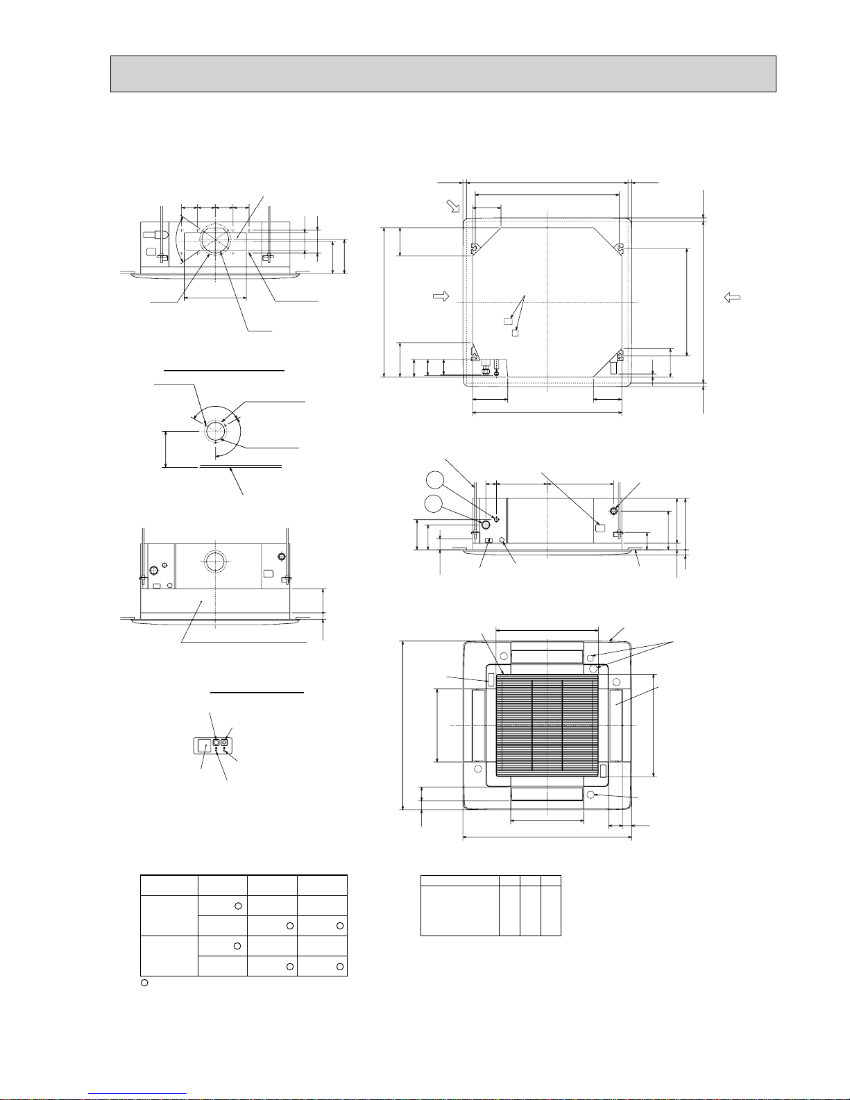
Page 15
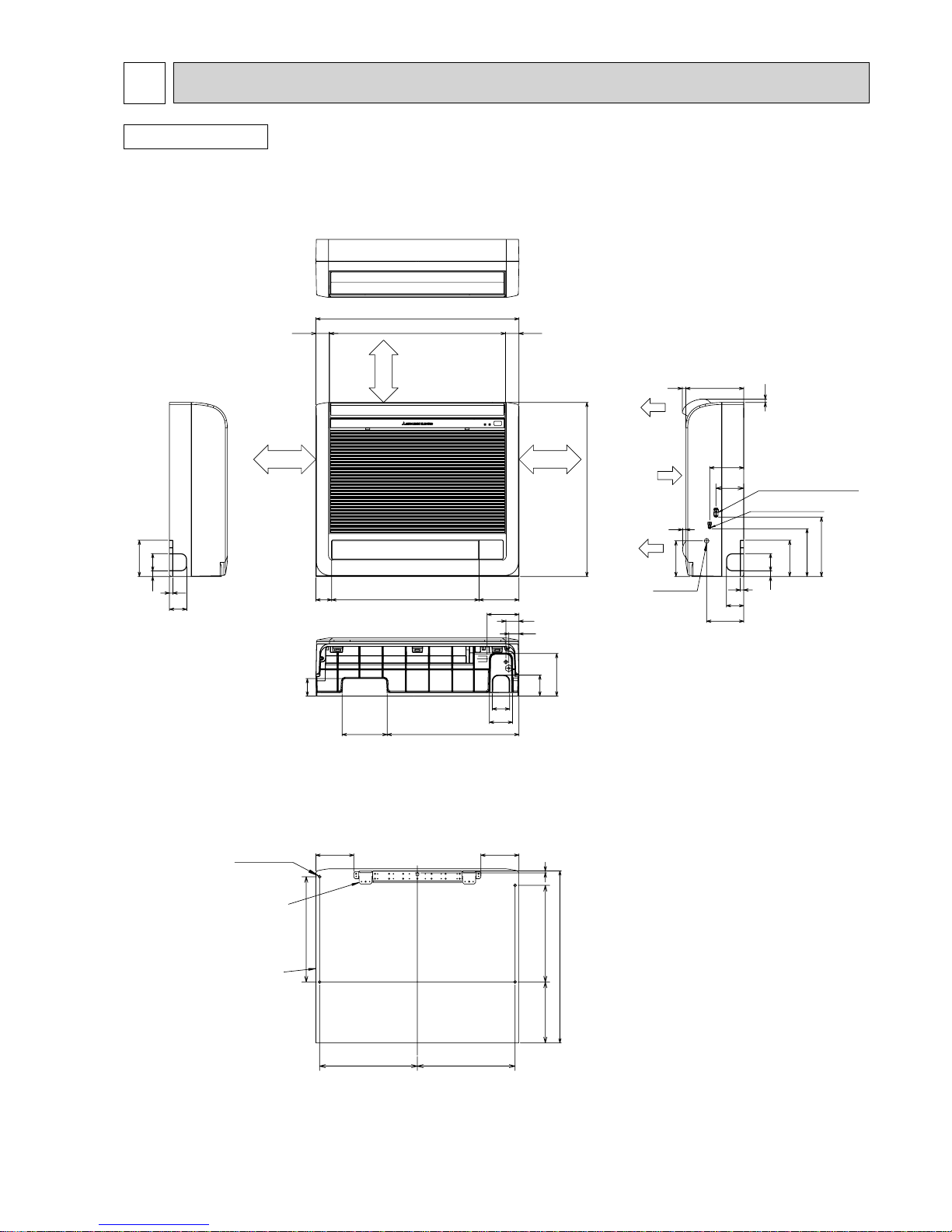
15
OUTLINES AND DIMENSIONS3
Unit : mm
60
12
19
60
125
147
454155
60
35
45
110
80
60
72
96
123
125
6019
12
60
128
118
165
205
20012
12
11
Gas pipe
25, 35::9.52(flared)3/8"
50::12.7(flared)1/2"
Liquid pipe
:6.35(flared)1/4
drain
Air in
Air out
Air out
46.5 46.5
600
700
54 508 137
607
More than
100mm
More than
100mm
More than
100mm
337 337
363
333210
593
7
131131
4-
:6 Hole
Indoor unit
Installation plate
INDOOR UNIT
MFZ-KA25VA
MFZ-KA35VA
MFZ-KA50VA
Page 16
16
SLZ-KA50VA(L)
SLZ-KA35VA(L)
SLZ-KA25VA(L)
Brand label
(Case of Wired remote controller)
Terminal block
Terminal block
87
Suspension bolt
M10 or 3/8
(procure locally)
1/4"F
flared connection
W 6.35mm
1/4"F
flared connection
W 6.35mm
W 9.52mm
flared connection
3/8"F
1/2"F
flared connection
Refrigerant pipe (liquid)
Refrigerant pipe (gas)
Models
W 6.35mm
flared connection
1/4"F
Refrigerant pipe
(liquid)
Refrigerant pipe
(gas)
W 12.7mm
W 9.52mm
flared connection
3/8"F
15~37 15~37
576~620
570
530
Grille
Fresh air
intake
Drain pipe
VP-25 connection
(O.D. W 32)
Vane motor
Drain hole
V/M
Air intake grille
55 35
35 55
Auto vane
Grille
Air intake hole
Air intake hole
Air outlet hole
Air outlet hole
301
301
Emergency operation switch(cooling)
Emergency operation switch(heating)
Operation lamp
DEFROST/STAND BY lamp
(WIRELESS PANEL)
Receiver
Detail drawing of fresh air intake
Ceiling surface
Cut out hole
W 73.4
Burring hole
3- W 2.8 hole
W 100
118
25
120°
120°
377
377
650
650
Suspension bolt
lower edge
230
18248
Wiring entry
Ceiling surface
235
208
27
+5
0
193
20
93
38~58
66121
17 202
56
57
31
Ceiling hole
Suspension bolt pitch
15~37 15~37576~620
420
570
335
199
352
335
Suspension bolt
pitch
Ceiling hole
V/M
V/M
V/M
MITSUBISHI
ELECTRIC
SLZ-KA25VAL
SLZ-KA35VAL
SLZ-KA50VAL
SLZ-KA25VA
SLZ-KA35VA
SLZ-KA50VA
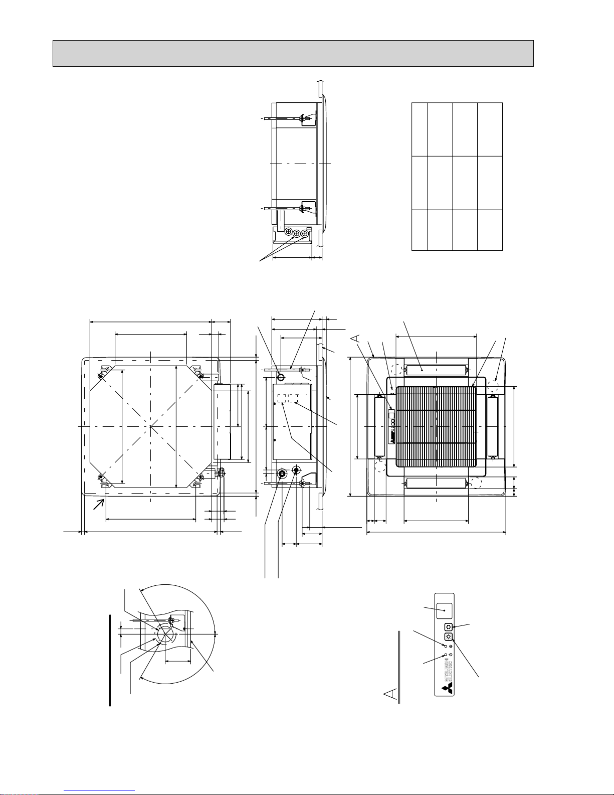
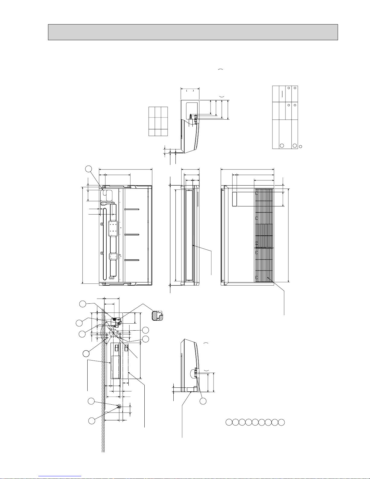
Unit : mm
Page 17
17
24
20
16
900
700
500
9
7
5
1060
860
660
LJHK
W12.7
SEZ-KD71VA(L)
SEZ-KD60VA(L)
SEZ-KD50VA(L)
SEZ-KD35VA(L)
700 752 798 660 7 600 800
W15.88
W9.52
W6.35
W9.52
1198
998
AModel
SEZ-KD25VA(L)
1152
952
B
1100
900
C
1060
860
D
11
9
E
1000
800
F
1200
1000
G
Air
outlet
Air
inlet
Terminal block
(Remote controller transmission line)
Drain pipe(O.D.W32)(Spontaneous draining)
1
Gas pipe
1
Liquid pipe
2
Refrigerant piping
flare connection (gas)
2
Refrigerant piping
flare connection (liquid)
Terminal block
(Indoor/outdoor connecting line)
Suspension bolt hole
4-14X30 Slot
Air filter
Control box
2XE-W2.9
2X2-W2.9
L-W2.9
Knockout hole W27
(Indoor/outdoor connecting line)
Knockout hole W27
(Remote controller transmission line)
10
170
57
More than 300
450
G
50
50~150
50
777
450
15
20
100
100X(E-1)=F
30
D (Duct)
625
(Suspension bolt pitch)
90
A
23
B (Suspension bolt pitch)
C
23 677
700
25100
23
150
(Duct)
116 70
270
102
More than 10mm
More than 20mm
25
49
10
88
100
100XJ=K 8812
1237100
20 157.5
20 H
200
37
Access door
Note2
Note1.Use M10 screw for the suspension bolt (field supply).
2.Keep the service space for the maintenance at the bottom.
3.This chart indicates for SEZ-KD50VA(L) model,which has 3 fans.
SEZ-KD25,35VA(L) models have 2 fans.
SEZ-KD60,71VA(L) models have 4 fans.
4.In case an inlet duct is used,remove the air filter(supply with
the unit), then install the filter(field supply) at suction side.
Make the access door at the appointed position properly
for service maintenance.
Ceiling surface
Access door
Required space for service and maintenance
Unit : mm
SEZ-KD25VA(L)
SEZ-KD35VA(L)
SEZ-KD50VA(L)
SEZ-KD60VA(L)
SEZ-KD71 VA(L)
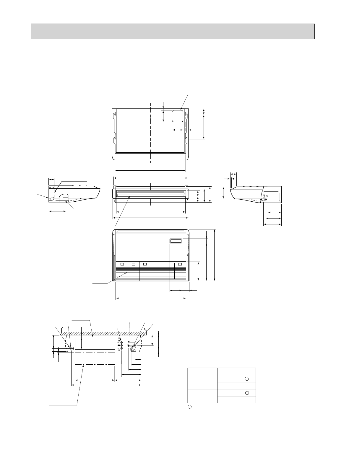
Page 18
18
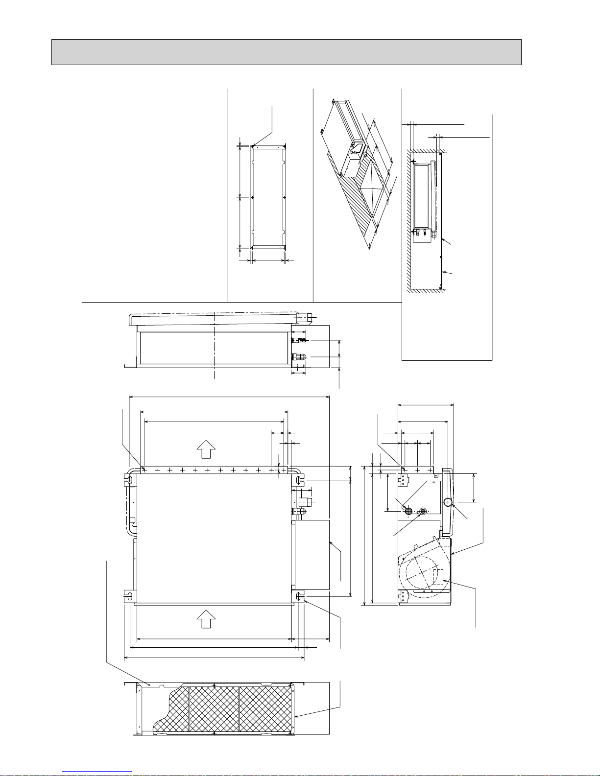
Unit : mm
SEZ-KC25VA
Make the access door at the appointed position properly
for service maintenance.
Ceiling surfaceAccess door
Required space for service and maintenance
Lifting plate
(4-14%30)
Air filter
80
Control box
Terminal bed
(Power source)
Bottom plate
23 664(Lifting bolt pitch)
710
The part air intake duct is attached.(+3)
(When the air intake duct is used)
610
50
150
790
582
204.5
42.5
30
225(+2)
15
148
13.55050
510
14127
56.5
(52)
(57)
129
55301 301
189
Detailed chart around the air intake duct flange(+3)
(Duct and flange should be supplied in the field.)
550(+1)
More than 20mm
More than 20mm
6- :3hole
55
50X11=550
16
2X12- : 3hole
14
459(Lifting bolt pitch)
15
113
Air outlet
Air inlet
450
50~150
300
450
2X3- :3hole
25
500
50~150
Note 1. Use M10 screw for the lifting bolt (field supply).
2. Keep the service space for the maintenance from the bottom
when the heat exchanger is cleaned.
3. The direction of air intake can be changed from the bottom to
the rear by attaching the bottom plate to the air intake side.
4. Drain Pan is changeable from right and left.
5. The dimension is changed, in case the optional long-life filter
is attached.
Rear Air-Intake spec. :Depth is increased by 30mm(+1)
Bottom Air-Intake spec. :Height is increased by 30mm(+2)
Refrigerant piping flare connection
(gas :9.52 copper tube):LP ········
Refrigerant piping flare connection
(liquid :6.35 copper tube):HP ········
Drain piping connection R1 (External thread) ········
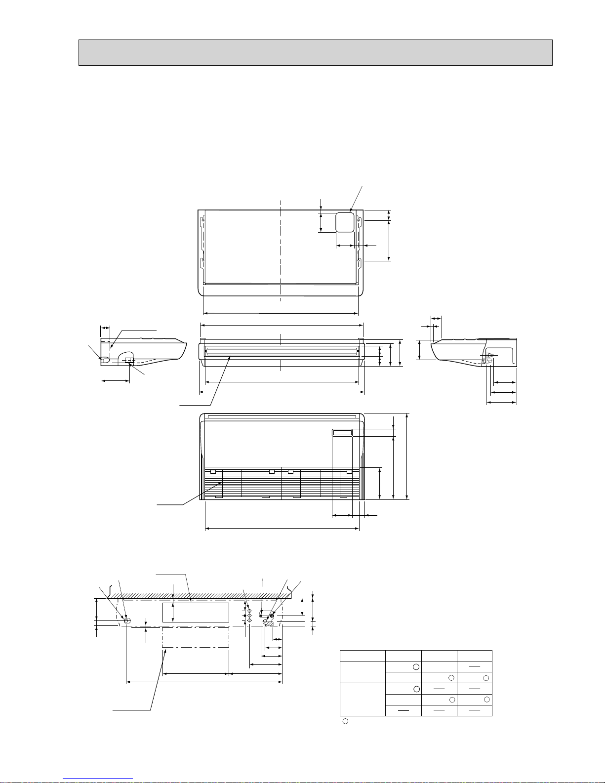
Page 19
19
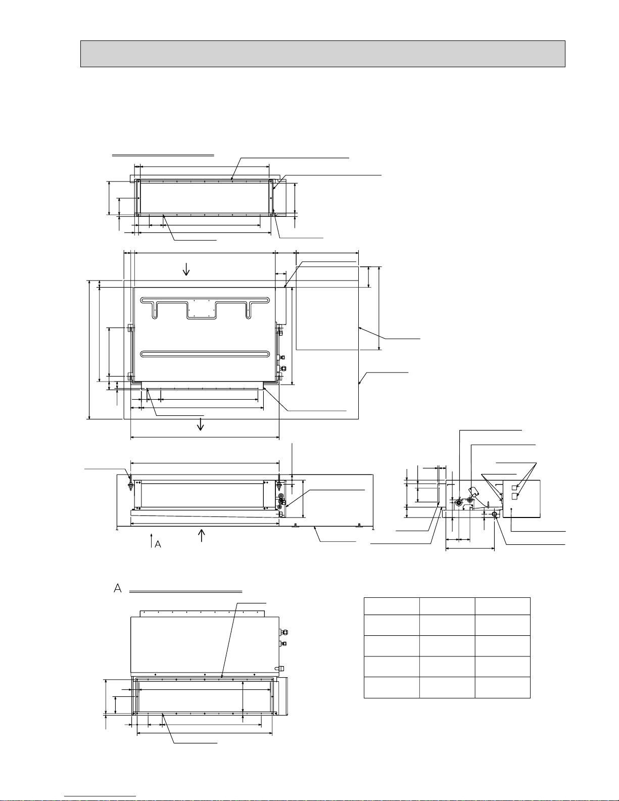
SEZ-KA35VA
SEZ-KA50VA
SEZ-KA60VA
SEZ-KA71VA
Unit : mm
(10) 50
50
880
7%100=700
100
40
9 % 2-W2.9 holes
1000
50
38
60
680
350
Suspension
bolt pitch
In case of bottom side suction,
mount the PLATE (A) on the rear side.
Air inlet (rear side) dimensions
240
1016
42
930
back side or bottom side.
29
955
7%100=700
100
77.5
12012.5
(Inlet size)
24-
W2.9 holes
50
27
Air inlet
(rear side)
Air outlet duct flange
120
12.5 240
(It is necessary to maintain a working
service area from the ceiling.)
150
32.5
25
(10) 50
77
600
700
Access door
Service space
Air outlet
Suspension bolt pitch
1070
(Suspension bolt pitch)
Electrical parts box
(1070)
20 or more30
20
PLATE (B)%2
After installation, remove the
transportation support PLATE (B).
25
(Inlet size)
215
450150
Electrical parts box
+ Select the either
SEZ-KA60VA
SEZ-KA50VA
Terminal block
3/8"F
flared connection
W9.52mm
W6.35mm
flared connection
1/4"F
Air outlet duct flange
51
25
930
(Inlet size)
39
955
7%100=700
100
77.5
(Inlet size)
215
Air inlet (bottom side) dimensions
24-W2.9 holes
flared connection
W6.35mm
Electrical parts box
2
%2-W2.9
holes
flared connection
W15.88mm
5/8"F
flared connection
1/2"F
W12.7mm
Refrigerant pipe
(gas)
Refrigerant pipe
(liquid)
1/4"F
flared connection
W6.35mm
SEZ-KA35VA
Models
Wiring entry
Refrigerant pipe (liquid)
Refrigerant pipe (gas)
Drain plug R1 (male)
108
94 80
25
350
1/4"F
SEZ-KA71VA
flared connection
W9.52mm
flared connection
5/8"F
W15.88mm
3/8"F
+ Select the either back side or bottom side.
Air inlet
(bottom side)
100
75 170
Suspension bolt
M10 or 3/8
(procure locally)
1100
270
Access door
PLATE (A)
Page 20
20
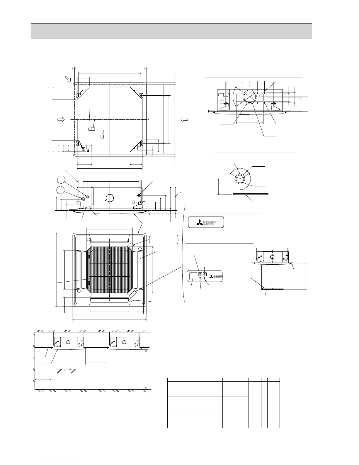
MITSUBISHI
ELECTRIC
MITSUBISHI
ELECTRIC
37728460
()
Ceiling hole
Branch duct hole
Drain pipe
connected to VP-25
Ceiling
Grille
Drain hole
Auto vane
(Air outlet)
Air intake grille
Ceiling
Cut out hole
Cut out hole
Cut out hole
Burring hole pitch
Burring hole pitch
Burring hole
Burring hole
Power supply wire,
Indoor unit/Outdoor unit
connecting wire entry
Indoor unit/Outdoor unit
connecting terminal block
Indoor power supply
terminal block(Option part)
Control wire entry
Air intake hole
Air intake hole
Air outlet hole
Air outlet hole
Connect the attached
drain socket.
Keep approximately
10 to 15mm space
between unit ceiling
and ceiling slab.
Branch duct hole
Fresh air
intake hole
Ceiling hole
Suspension bolt pitch
Suspension bolt pitch
Remote controller
terminal block
Suspension bolt
M10 or W3/8
(7.5)(7.5)
605
+35
- 5
620
DEFROST/STAND BY lamp
Receiver
Operation lamp
In case of standard grille : PLP-6BA / PLP-6BAMD
In case of wireless remote controller : PLP-6BALM
Auto Grille
Air intake grille up/down discharge
Emergency operation
switch<Cooling>and
Emergency Up/Down switch<Up>
160
160
500
500
597
83
36
950
8336
950
597
A
17
+5
0
B
35
190
156
105
140
50~70
160
840
150
90
C
D
840
187.5
20~45
860~910
20~45
810
20~45860~91020~45
24
160
++
+
+
+
+
+
+
+
M
M
M
M
120°
120°
:175
:125
167
158
Vane motor
2
1
Drain pump clean hole
and Drain emergency
drainage hole
130
100
70°
155
350
90 100 100 90
Detail drawing of fresh air intake hole
Detail connecting of branch duct(Both aspects)
3-:2.8
14-:2.8
:150
:100
Emergency operation
switch<Heating>and
Emergency Up/Down switch<Down>
In case of Auto-Grille : PLP-6BAJ
Suspension bolt
lower edge
170
+
Models
241 258
87
400
AB CE
80
85
74
D
77
PLA-RP35/50BA
PLA-RP60BA
PLA-RP71BA
PLA-RP71BA2
Refrigerant pipe
···:6.35
Flared connection
···1/4 inch
Refrigerant pipe
:6.35
Flared connection
1/4 inch
Refrigerant pipe
···:9.52
Flared connection
···3/8 inch
Refrigerant pipe
···:12.7
Flared connection
··1/2 inch
Refrigerant pipe
···:15.88
Flared connection
···5/8 inch
Ceiling
Air intake grille
Max. 4.0m
L.L Filter
Ceiling
Grille
Indoor unit
1500mm
or more
1000mm
or more
3000mm or more
1800mm or more
from floor
For high
attachment
Indoor unit
Obstacle
Floor
Note : 1. Please choose the Grille from a standard grille, auto-grille.
2. As for drain pipe, please use VP-25(O.D. :32 PVC TUBE).
Drain pump is included.
Max. lifting height is 850mm from the ceiling.
3. As for suspension bolt, please use M10 or W3/8. (Procured at local site)
4. Electrical box may be removed for the service purpose.
Make sure to slack the electrical wire little bit for control/ power wires connection.
5. The height of the indoor unit is able to be adjusted with the grille attached.
6. For the installation of the optional high efficiency filter or optional multi-functional
casement.
1) Requires E or more space between transom and ceiling for the installation.
2) Add 135 mm to the dimensions + marked on the figure.
3) The optional high efficiency filter must be used jointly with optional multi-functional
casement.
7. When installing the branch ducts, be sure to insulate adequately.
Otherwise condensation and dripping may occur.
(It becomes the cause of dew drops/water dew.)
8. As for necessary installation/service space, please refer to the left figure.
PLA-RP35BA PLA-RP50BA PLA-RP60BA PLA-RP71BA PLA-RP71BA2 Unit : mm
Page 21
21
PLA-RP60,71AA
PLA-RP35,50AA
Models
241A258B80
C
Receiver
Operation lamp
DEFROST/STAND BY lamp
Emergency operation switch (cooling)
A (WIRELESS PANEL)
Emergency operation switch (heating)
Branch duct hole
(Cut out hole)
W175
W150
14 - W2.8
Burring hole
350
90
70
"
100 100 90
100
130
155
167
Suspension bolt pitch
Ceiling hole
Branch
duct hole
Suspension bolt pitch
Ceiling hole
840
197 159
159
605
159192
98
89
C
840
860 - 91020 - 45 20 - 45
20 - 4520 - 45
Fresh air intake
Branch duct hole
860 - 910
810
159
16
Terminal block
Drain pipe
VP-25connection
(O.D.W32)
Ceiling surface
Power line entry
Suspension bolt lower edge
Suspension bolt M10
or W3/8
Control wire entry
Feeding hole
(Drain pump)
37428660
17
+5
0
30
190
170
140
50 - 70
105
A
B
1
2
High efficiency filter
& Fresh air intake casement (option)
17
+5
0
135
Air outlet hole
Vane motor
Auto vane
Drain hole
Grille
Air outlet hole
Air intake hole
411
Air intake hole
Air intake grille
577
77 51
M
M
M
A
M
950
51 77
950
577
411
RP35, 50
Use the current nuts meeting the pipe size of the outdoor unit.
Available pipe size
: Initial flare nut size
LIQUID SIDE
GAS SIDE
RP60 RP71
:6.35 :6.35 —
:9.52 :9.52 :9.52
:12.7 — —
:15.88 :15.88 :15.88
(Unit : mm) (Unit : mm)
Detail drawing of fresh air intake
3 - W2.8
Burring hole
W125
Burring hole pitch
W100
(Cut out hole)
Ceiling surface
120"
120"
158
PLA-RP35AA PLA-RP50AA PLA-RP60AA PLA-RP71AA Unit : mm
Page 22

22
Unit : mm
PCA-RP50KA
(Drainage)
When drain socket
is installed
2
246
When drain socket
is installed
233
When electrical box
is pulled down
Electrical box
NOTES.
1.Use M10 or W3/8 screw for anchor bolt.
2.Please be sure when installing the
drain pump (option parts),
refrigerant pipe will be only upward.
Electrical box
233
Air outlet
Air intake
9
678
5
1
234
Knock out hole for upper drain pipe arrangement
Knock out hole for fresh air intake ø100
Knock out hole for wiring arrangement 2-ø22
Knock out hole for wiring arrangement 2-ø26
Drainage pipe connection(26mmI.D.)
Drainage pipe connection(for the left arrangement)
Knock out hole for left drain-piping arrangement
Refrigerant-pipe connection(gas pipe side/flared connection)
Refrigerant-pipe connection(liquid pipe side/flared connection)
1
In case of the rear pipe arrangement, make sure to
remove the shaded portions from the independent piece.
Then put the independent piece back in initial position.
(The heat exchanger might be clogged because of dust)
5
10
51
246
(Drainage)
(gas ø12.7)
(liquid ø6.35)
150
62140
18
917(Suspension bolt pitch)
320
680
80
84 88
195
230
57
254
476
680
182 85
878
8
48
260
24
38
85 86 2
126
169
121
190
18
38
120°
960 22
853
124 76
46
190
75
387461
3
8
Ceiling
5
1
4
7
184
203
ø125
6
9
37
138
2
[FRONT VIEW]
Accessory···Drain socket (I.D. 26)
(71)
Page 23
23
Unit : mm
(Drainage)
When drain socket
is installed
2
246
When drain socket
is installed
233
Air intake
5
4
123
6
789
Knock out hole for upper drain pipe arrangement
Knock out hole for fresh air intake ø100
Knock out hole for wiring arrangement 2-ø22
Knock out hole for wiring arrangement 2-ø26
Drainage pipe connection(26mmI.D.)
Drainage pipe connection(for the left arrangement)
Knock out hole for left drain-piping arrangement
Refrigerant-pipe connection(gas pipe side/flared connection)
Refrigerant-pipe connection(liquid pipe side/flared connection)
NOTES.
1.Use M10 or W3/8 screw for anchor bolt.
2.Please be sure when installing the
drain pump (option parts),
refrigerant pipe will be only upward.
Air outlet
233
Electrical box
When electrical box
is pulled down
Electrical box
9
7
In case of the rear pipe arrangement, make sure to
remove the shaded portions from the independent piece.
Then put the independent piece back in initial position.
(The heat exchanger might be clogged because of dust)
5
10
51
246
A
B
236
150
62140
18
1237(Suspension bolt pitch)
320
680
80
84 88
195
230
57
254
476
680
182 85
1198
848
260
24
38
85 86 2
126
16937
121
138
190 1
18
38
120°
1280 22
1173
124 76
46
190
75
387461
2
3
8
5
1
4
ø125
6
8
[FRONT VIEW]
Ceiling
(Drainage)
(gas ø15.88)
(liquid )
Accessory···Drain socket (I.D. 26)
Flare nut ø6.35 (RP60 only)
A
B
60
179
203
71
180
200
5 LIQUID SIDE
4 GAS SIDE
:Initial flare nut size
Use the current nuts meeting the pipe size of the outdoor unit.
Available pipe size
RP60
ø6.35
ø9.52
ø15.88
RP71
ø9.52
ø15.88
(71)
PCA-RP60KA
PCA-RP71KA
Page 24
24
PCA-RP50GA Unit : mm
NOTES:
1. Use M10 or W3/8 screws for anchor bolt.
2. When optional drain pump is installed, always provide
upward piping for refrigerant piping.
180
210
157
15
85
182 liquid
201 gas
241 (Drainage)
Air intake
918
161 90
254
680
506 56
Electrical box
226
70
17
150
140
70
320
80
933 (suspension bolt pitch)
983
1000
Air outlet
81
904
76
525
928
352
263
171
138
86
46 175 1
131
38
38
79
161
32
179
42
6~7
Ceiling
Electrical box
[Front view]
When electrical
box is pulled
down
:15.88
:12.7
:6.35
Available pipe size
:9.52
GAS SIDE
LIQUID SIDE
RP50
Use the current nuts meeting the pipe size of the outdoor unit.
: Initial flare nut size
(Unit : mm)
1 Drainage pipe connection (26mm I.D.)
2 Drainage pipe connection (for the left arrangement)
3 Knock out hole for left drain-piping arrangement
4 Refrigerant-pipe connection (gas pipe side/flared connection)
5 Refrigerant-pipe connection (liquid pipe side/flared connection)
6 Knockout hole for upper drain pipe arrangement
7 Knockout hole for left drain pipe arrangement
8 Knockout hole for wiring arrangement
Page 25
25
PCA-RP50GA2 Unit : mm
PCA-RP60GA
PCA-RP71GA
161 90
254
680
506 56
1240 (suspension bolt pitch)
140
150
320 80
17
70
1290
1214
210
180
81 76
1310
Air outlet
1228
Air intake
85
182
201
241
15
157
(liquid)
(5/8F gas)
(Drainage)
Electrical box
70
226
Electrical box
When electrical
box is pulled
down
[ Front view ]
Ceiling
32
179
161
38
3879
42
6~7
525
1235
416
263
171
138
86
131
175 1
46
: Initial flare nut size
GAS SIDE
LIQUID SIDE
Use the current nuts meeting the pipe size of the outdoor unit.
Available pipe size
RP71RP60
:6.35
:9.52
:15.88
:9.52
:15.88
(Unit : mm)
:15.88
:12.7
:6.35
:9.52
RP50
1 Drainage pipe connection (26mm I.D.)
2 Drainage pipe connection (for the left arrangement)
3 Knock out hole for left drain-piping arrangement
4 Refrigerant-pipe connection (gas pipe side/flared connection)
5 Refrigerant-pipe connection (liquid pipe side/flared connection)
6 Knockout hole for upper drain pipe arrangement
7 Knockout hole for left drain pipe arrangement
8 Knockout hole for wiring arrangement
NOTES:
1. Use M10 or W3/8 screws for anchor bolt.
2. When optional drain pump is installed, always provide
upward piping for refrigerant piping.
Page 26
26
Unit : mm
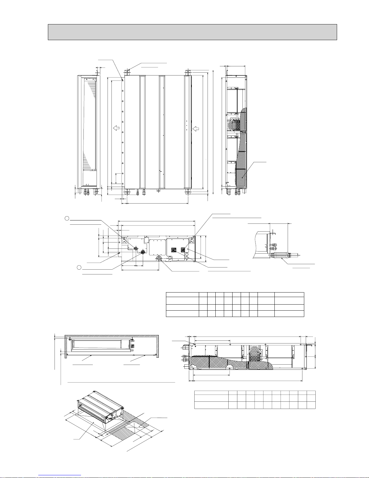
PEAD-RP35, 50, 60, 71JA
Air Filter
Suspension bolt hole
4-14x30 Slot
Air
outlet
Air
inlet
2xE-
:
2.9
2×2-:2.9
Refrigerant piping
Flare connection (liquid)
2
1
Refrigerant piping
Flare connection (gas)
Drain pump
Control box
Terminal block
(Indoor/Outdoor connecting line)
Terminal block
(Remote controller transmission line)
Drain pipe(O.D.:32)
(Spontaneous draining)
Drain pipe
(O.D.:32)
:15.88
Outdoor unit (SUZ): :6.35
Outdoor unit : :9.52
*
:6.35:12.7
Liquid pipe
Gas pipe
Model A
1200
900 954 860 9
E11D
1060
C
1100B1154
PEAD-RP60JA
PEAD-RP35,50JA 1000
1000
F
858800
G
1058
40
21018
G21
250
12233
15
58
57
10
100
100x(E-1)=F
A
B(Suspension bolt pitch)
C
23
643 (Suspension bolt pitch)
30
57
20
D (Duct)
178 (Duct)
40
23
10
238
32 700
732
136
67
356
100
41
217
NOTE 1. Use M10 screw for the Suspension bolt (field supply).
2. Keep the service space for the maintenance at the bottom.
3. This chart indicates for PEAD-RP60
•
71JA models, which have 2 fans.
PEAD-RP35
•
50JA models have 1 fan.
4. In case that the inlet duct is used, remove the air filter (supplied with
the unit), then install the filter (field supply) at suction side.
Less than 300mm
175±5mm
Less than 700mm
Drain hose (I.D.:32)
<accessory>
(Actual length)
1020
819
JQS
340
R
54 260 4 780 10 40.5 273 4
440P10
N
990
M4L49K
330
PEAD-RP35,50JA
PEAD-RP60,71JA 1200
1000
HModel
N-
:
2.9
K
Kx(L-1)=M
J
112 112
11
Q
Qx(R-1)=SP
J
6
More than 20mm
More than 10mm
Make the access door at the appointed position properly for service maintenance.
Ceiling surface
Access door
50
250~300
450
50
H
777
450
More than 300
Access door
Note2
Required space for service and maintenance
:15.88
:9.52
1200 1110601100 1154
PEAD-RP71JA
1000 1058
* Setting at shipment
Page 27
27
PEAD-RP35, 50, 60, 71JAL
Air Filter
40
21018
G
21
15
58
NOTE 1. Use M10 screw for the Suspension bolt (field supply).
2. Keep the service space for the maintenance at the bottom.
3. This chart indicates for PEAD-RP60
•
71JAL models, which
have 2 fans. PEAD-RP35
•
50JAL models have 1 fan.
4. In case of the inlet duct is used,remove the air filter (supplied
with the unit), then install the filter (field supply) at suction side.
1020
819
JQS
340
R
54 260 4 780 10 40.5 273 4
440
P10N
990
M4L49K
330
PEAD-RP35,50JAL
PEAD-RP60,71JAL
1200
1000
HModel
N-
:
2.9
K
Kx(L-1)=M
J
112 112
11
Q
Qx(R-1)=SP
J
6
More than 20mm
More than 10mm
Make the access door at the appointed position properly for service maintenance.
Ceiling surface
Access door
50
250~300
450
50
H
777
450
More than 300
Access door
Note2
Required space for service and maintenance
Suspension bolt hole
4-14x30 Slot
Air
outlet
Air
inlet
2xE-:2.9
57
10
100
100x(E-1)=F
A
B(Suspension bolt pitch)
C
23
643 (Suspension bolt pitch)
30
57
20
D (Duct)
Drain pipe(O.D.:32)
2×2-
:
2.9
Refrigerant piping
Flare connection (liquid)
2
1
Refrigerant piping
Flare connection (gas)
Control box
Terminal block
(Indoor/Outdoor connecting line)
Terminal block
(Remote controller transmission line)
250
33
122
178 (Duct)
40
23
10
32 700
732
136
67
356
100
217
175±5mm
<accessory>
Drain hose (I.D.
:
32)
(Actual length)
:15.88
Outdoor unit (SUZ): :6.35
Outdoor unit : :9.52
*
:6.35:12.7
Liquid pipe
Gas pipe
Model A
1200
900 954 860 9
E11D
1060
C
1100B1154
PEAD-RP60JAL
PEAD-RP35,50JAL 1000
1000
F
858800
G
1058
:15.88
:9.52
1200 1110601100 1154
PEAD-RP71JAL
1000 1058
* Setting at shipment
Unit : mm
Page 28
28
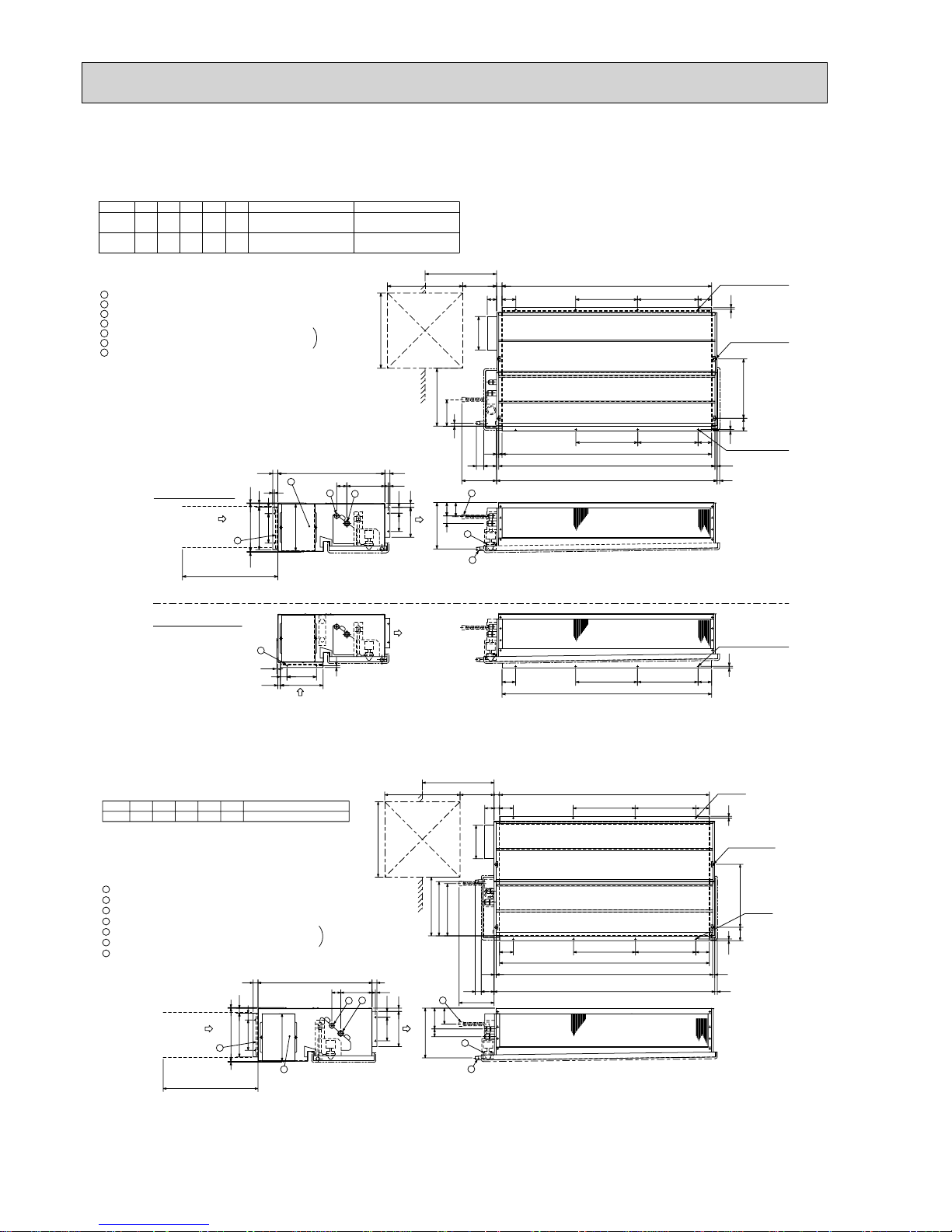
PEAD-RP35EA2 Unit : mm
PEAD-RP50EA
PEAD-RP60EA
PEAD-RP71EA
2
1
3
4
5
6
7
Refrigerant piping flare connection (liquid : F copper tube):HP
Refrigerant piping flare connection (gas :G copper tube):LP
Drain R1(External thread)
Electrical parts box
Drain Pump (Option)
Drain Pipe (Option) ... Flexible joint VP-25(I.D.
:
32)
Filter
R407C Outdoor unit : 9.52
F
R410A Outdoor unit : 6.35 +
R407C Outdoor unit : 9.52 +
Outdoor unit (SUZ) : 6.35
EDCBA
804830
-
305772
Model
RP60
R407C Outdoor unit : 15.88
G
R410A Outdoor unit : 12.7 +
15.88
104410702902801012
RP35,50
+ Initial flare nut size
2
1
3
4
Air inlet
Air outlet
Access door
55
50~150
81
197
Service space:500 or more
Keep duct-work length 850mm or more.
Be sure to apply the air filter
near the air inlet grille.
5
6
75
44
18
365~465
B 81
10
56 355
7
159
243
Air outlet
Air inlet
7
Lifting bolt hole
(14s22)
10-:3 (RP35,50)
12-:3 (RP60)
In case of rear inlet
In case of bottom inlet
10-:3 (RP35,50)
12-
:
3 (RP60)
D
30
C
10
81BC
A
450
450
10-:3 (RP35,50)
12-
:
3 (RP60)
176
40
288
256
3.5
3.5
10
109
179
10
35
24
30640
30
21
277
80
45
282
13
13E
A
61 227
29
85
40
176
10
15
3.5
256
BC 81
10
81
A
Set
(Unit : mm)
15.8810441070290
FEDCBA
2801012
Model
RP71
+
Initial flare nut size
(Unit : mm)
7
44
243
308
323
75
6
5
13
Refrigerant piping flare connection (liquid :9.52 copper tube):HP
Refrigerant piping flare connection (gas :F copper tube):LP
Drain R1 (External thread)
Electrical parts box
Drain Pump (Option)
Drain Pipe (Option) ... Flexible joint VP25(I.D.:32)
Filter
Service space:500 or more
81
365~465
197
81
50~150
55
29
Access door
Air outlet
Air inlet
4
3
1
2
7
6
5
4
3
2
1
113
307
122
12-:3
(14x22)
Lifting bolt hole
45
Set
210
12-:3
450
450
140
282
680
3.5
3.5
30
319
261
181
40
30
A
C
B
81
10
375
10
80
CB81
A
E
13
30D
20
35
30
1053 169
Keep duct-work length 850mm or more.
Be sure to apply the air filter
near the air inlet grille.
Page 29
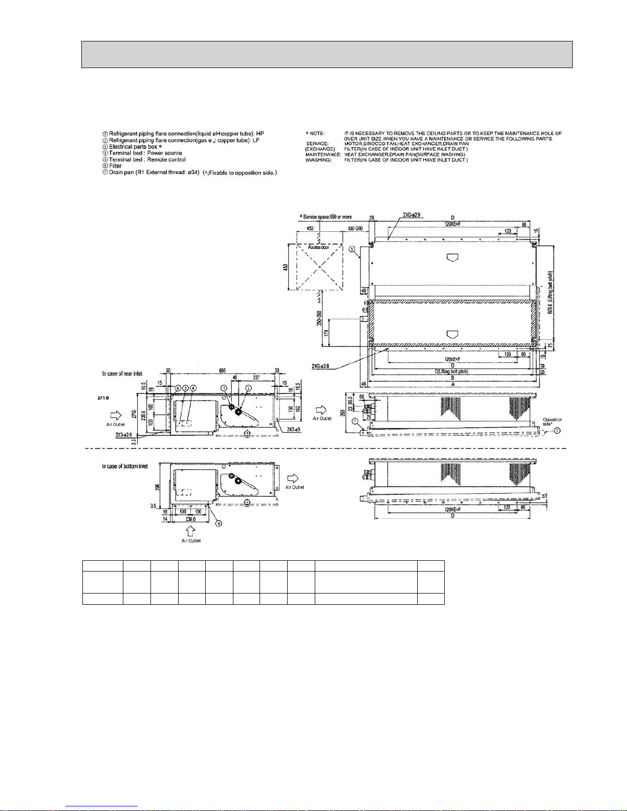
29
PEAD-RP60GA Unit : mm
PEAD-RP71GA
Model ABCDE
7
7
8
9.52 15.88
15.88
(Unit : mm)
8
F
GHJ
RP60
RP71
1125
1125
1090
1090
1050
1050
1012
1012
840
840
Outdoor unit(SUZ) : 6.35
Other outdoor unit : 9.52 +
+ Initial flare nut size
Page 30
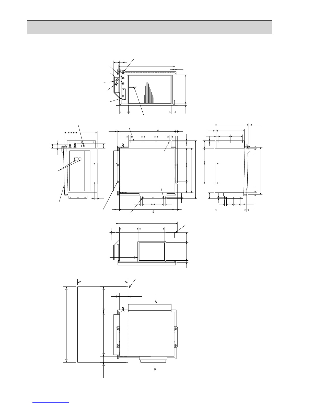
30
50
55
530
690
(130)
22.5
4070
105 510 35
40 40
650
15
15
730
155 155155
14 220 120
3.2
300242
2656075
35
45
20 345
11
11
672
22.5
20 20690
15
2512512525
100
600
70
(530)
300
900
(10)
25
562
21
(10)381
858525
15
70
11
14514524.5
33920
418
90
200 200
250 175
Terminal
block
4-12 30
oblong
Suspension
bolt holes
Air intake
Air outlet
Service space (opening) in the ceiling
Heat insulator t10
(Drainage pan)
Room temperature thermistor
Drainage pan connection R1
Wiring entry(2-:22holes)
Refrigerant-pipe flared
connection :15.88(5/8)
Refrigerant-pipe flared
connection :9.52(3/8)
Electrical parts box
Service panel
(Condenser/evaporator
temperature thermistor)
Service panel
(Room temperature
thermistor)
Air intake
Air intake duct flange
14-:2.9 holes
For air intake
duct connection
Heat insulator t10
Air outlet duct flange
Air outlet
(Drainage pan)
12-:2.9 holes
For air outlet
duct connection
Mounting plate
PEA-RP71EA Unit : mm
Page 31

31
10
69
800
302.5
500 Bolt pitch for installation
150
22.3
Handle
550
280
164.5
99.5
170.5
23
Service panel
Service port
285
344.5
44
400
Air in
Air out
Air in
17.5
Bolt pitch for
installation
304~325
40
Liquid refrigerant pipe joint
Refrigerant pipe (flared) :6.35
Gas refrigerant pipe joint
Refrigerant pipe (flared) :9.52
43
35
2 holes 10X21
Drain hole :33 (SUZ-KA25/KA35VAH)
REQUIRED SPACE
Basically open 100mm or more
without any obstruction in front
and on both sides of the unit.
350mm or more
200mm or more
100mm or more
100mm or more
Open two sides of left,
right, or rear side.
Drain hole :42 (SUZ-KA25/KA35VA)
Unit: mm
OUTDOOR UNIT
SUZ-KA25VA SUZ-KA25VAH
SUZ-KA35VA SUZ-KA35VAH
Page 32

32
Unit: mm
30
35
155
90
198
40
515
299
66
34
51
330
360
850
430
500
80
121
840
Open as a rule
500mm or more if
the front and both
sides are open
100mm or more
200mm or more if
there are obstacles
to both sides
Open as a rule
500mm or more if the back,
both sides and top are open
350mm or more
100mm or more
Service panel
Gas refrigerant
pipe joint
Refrigerant pipe(flared)
:12.7·····(SUZ-KA50VA)
:15.88···(SUZ-KA60/KA71VA)
Liquid refrigerant
pipe joint
Refrigerant pipe(flared)
:6.35·····(SUZ-KA50/KA60VA)
:9.52·····(SUZ-KA71VA)
REQUIRED SPACE
Drain holes :33
SUZ-KA50VA
SUZ-KA60VA
SUZ-KA71VA
Page 33

33
WIRED REMOTE CONTROLLER
Unit : mm
130
120
19.5
43.5
Page 34

34
WIRELESS REMOTE CONTROLLER
Installation area
• Area in which the remote controller is not exposed to direct sunshine
• Area in which there is no heating source nearby
• Area in which the remote controller is not exposed to cold (or warm) winds
• Area in which the remote controller can be operated easily
• Area in which the remote controller is beyond the reach of children
Installation method
Attach the remote controller holder to the desired location using two tapping screws.
Place the lower end of the controller into the holder.
Wireless remote controller (Accessory)
Wall
Remote controller holder (Accessory)
Fixing screw (Accessory)
• The signal can travel up to approximately 7 meters (in a straight line) within 45
degrees to both right and left of the center line of the receiver.
In addition, the signal may not be received if there are interferences of fluorescent
lights or strong sunlight.
ON/OFF
RESET
TOO
WARM
TOO
COOL
MODE
AUTO COOL
DRY
HEAT
FAN
VANE
SELECT
TIME
h
57 17.5
140
Unit : mm
SLZ-KA25/35/50VAL SEZ-KC25,KA35/50/60/71VA(Option)
Page 35

35
WIRELESS REMOTE CONTROLLER
Unit : mm
159.3
55
58
19
Page 36

36
4
WIRING DIAGRAM
INDOOR UNIT
NOTE:1. About the outdoor side electric wiring, refer to the outdoor unit electric wiring diagram for servicing.
2. Use copper conductors only. (For field wiring)
3. Symbols below indicate :
/: Terminal block, : Connector
GRN
S1
1
2
CN202
12-24V
TB
S3
RED
BLK
TO OUTDOOR
UNIT
CONNECTING
INDOOR ELECTRONIC
CONTROL P.C. BOARD
WHT
230V~
S2
WHT
CN201
1
2
LD103
3
3
CN112
CN113
111
RT11
RT15
5
3
1
2
4
6
CN
1
2
3
4
RT12
RT13
RT14
CN
1Y1
CN
1X1
LS1
LS2
CN212
T11
F11
NR11
DB111
ML1
MV1
55
CN
151
MF2
MF1
5
5
ML2
152
MV2
55
CN
106
CN CN
125
62
6
4
2
1
5
3
CN211
6
4
2
1
5
3
DISP REC
P.C.BOARD
SYMBOL
DB111
F11
LS1
LS2
MF1
MF2
ML1
SYMBOL
ML2
MV1
MV2
NR11
RT11
RT12
RT13
NAME
DIODE STACK
FUSE (T3.15AL250V)
DAMPER LIMIT SWITCH (OPEN)
DAMPER LIMIT SWITCH (CLOSE)
UPPER INDOOR FAN MOTOR
LOWER INDOOR FAN MOTOR
DAMPER LOCK MOTOR (RIGHT)
NAME
DAMPER LOCK MOTOR (LEFT)
HORIZONTAL VANE MOTOR
DAMPER MOTOR
VARISTOR
ROOM TEMPERATURE THERMIST OR
INDOOR COIL THERMISTOR (MAIN 1)
INDOOR COIL THERMISTOR (SUB)
SYMBOL
RT14
TR15
T11
NAME
INDOOR COIL THERMISTOR (MAIN 2)
INDOOR COIL THERMISTOR (MAIN 3)
TRANSFORMER
[LEGEND]
MFZ-KA25VA
MFZ-KA35VA
MFZ-KA50VA
Page 37

3737
SLZ-KA25VAL SLZ-KA25VA
SLZ-KA35VAL SLZ-KA35VA
SLZ-KA50VAL SLZ-KA50VA
SWE
GRILLE
OFF
ON
SW3
OFF
54321
ON
SW2
OFF
54321
ON
WHT
RED
RED
CNDK
(POWER
BOARD)
ZNR
X1
RED
ORN
YLW
YLW
BLU
BLU
BLU
BLU
LED3
CN2L
CN32 CN51 CN41
(REMOCON)
BLU
TO OUTDOOR UNIT
S3
ORN
MF
MV
MV
MV
MV
5
5
5
5
H2
5
31
P.B
3
TB4
S1
S2
TB15
1
2
TO MA-REMOTE
CONTROLLER
DC8.7-13V
}
REMOTE
CONTROLLER
W.R
9
5
CN6V
(VANE)
GRN
BLU
WHT
ORN
RED
YLW
YLW
X5
X5 X4
X4X7X6
X6 X7
97531
C1
BLK
WHT
BLU
YLW
BRN
RED
I.B
CNB
BZ
LED2
LED1
SW1
SW2
RU
W.B
9
CN22
1
(2 PHASE)
CN29
BLK
WHT
RED
(INTAKE)
(LIQUID)
CN31
3
CN20
CN21
112
212
2
12
DS
TH5
TH1
TH2
X1
YLW
BLU
(D·U·M)
CNP
RED
(D·HEATER)
CNC
313131
CND
(POWER)
ORN
FUSE
(CONTROL)
CN3C
BLU
3131
LED1
12
12
TRANS
DC13.1V
CN2S(WHT)
AC220-240V
CNSK(RED)
WHT
BLK
2
1
(POWER
BOARD)
CN2D
WHT
LED2
* Case of wireless model
* Case of wired model
See fig:+1
MODELS
KA25
KA35
KA50
<fig:+1>
ON
OFF
12345
ON
OFF
12345
ON
OFF
12345
SW2
YLW
YLW
RED
ORN
YLW
WHT
BLU
17451089236
DP
GRY
VLT
BLU
YLW
ORN
RED
BRN
SKYBLU
PINK
WHT
(WIRELESS)
CN90
987654321
654321
(FAN)
FAN
WHT
BRN
RED
ORN
YLW
BLU
VLT
GRY
PINK
SKY BLU
123456789
(DRAIN)
WHT
+ For details on how to operate self-diagnosis, refer to the service manuals etc.
SWITCH(COOLING ON/OFF)
LED(RUN INDICATOR)
SWITCH(HEATING ON/OFF)
LED(HOT ADJUST)
BUZZER
RECEIVING UNIT
WIRELESS REMOTE CONTROLLER BOARD
SW2
SW1
LED2
RU
LED1
BZ
W.B
H2
DP
DS
MV
MF FAN MOTOR
VANE MOTOR
DRAIN PUMP
DRAIN SENSOR
DEW PREVENTION HEATER
C1 CAPACITOR(FAN MOTOR)
FUSE(T6.3AL250V)
X7
X6
X5
X4
X1
ZNR
RELAY(FAN MOTOR Me)
RELAY(FAN MOTOR Hi)
RELAY(FAN MOTOR LL)
RELAY(FAN MOTOR Lo)
DRAIN PUMP/DEW PREVENTION HEATER
VARISTOR
SYMBOL NAME
SWITCH(CAPACITY CODE)
SW3
SW2
SWE SWITCH(EMERGENCY OPERATION)
SWITCH(MODE SELECTION)
TRANSMISSION(INDOOR-OUTDOOR)
LED1
LED2
LED3
POWER SUPPLY(I.B)
POWER SUPPLY(I.B)
CN51
CENTRALLY CONTROL
FUSE
P.B
CONNECTOR(HA TERMINAL-A)
CONNECTOR(REMOTE SWITCH)
CONNECTOR(LOSSNAY)
CN41
CN32
CN2L
INDOOR CONTROLLER BOARD
INDOOR POWER BOARD
I.B
NAMESYMBOL
TB4
TB15
TH1
TH2
TH5
TERMINAL BLOCK(INDOOR/OUTDOOR CONNECTING LINE)
TERMINAL BLOCK(REMOTE CONTROLLER
TRANSMISSION LINE)
ROOM TEMP.THERMIST OR
(0/15k, 25/5.4k DETECT)
PIPE TEMP.THERMIST OR/LIQUID
(0/15k, 25/5.4k DETECT)
COND./EVA.TEMP.THERMISTOR
(0/15k, 25/5.4k DETECT)
[LEGEND]
Notes:
1. SymboIs used in wiring diagram above are, : Connector, : Terminal (block).
2. Indoor and outdoor connecting wires have poIarities, make sure to match terminal numbers (S1, S2, S3) for correct wirings.
3. Since the outdoor side electric wiring may change, be sure to check the outdoor unit electric wiring diagram for servicing.
Page 38

38
SEZ-KD25VA(L)
SEZ-KD35VA(L)
SEZ-KD50VA(L)
SEZ-KD60VA(L)
SEZ-KD71 VA(L)
1~
M
135
311456734
12
4231
4123 67895
54321678
1324
912
3
LED1
Optional Parts
L1:only
SEZ-KD71VA(L)
INSIDE SECTION OF CONTROL BOX
CN22
(Red)
CN3C
CNMF
SW2SW1
CN90
CN32
CN20CN44
CN4F
CN41
SWE
ON
OFF
CN51
(Blue)
TO MA REMOTE
CONTROLLER
FS
TH2 TH5 TH1
Fan motor
TB15
CN4F
Optional Parts
CN2L
(Blue)
LED3
LED2
I.B.
S1
TB4
S3
S2
TO
OUTDOOR
UNIT
Drainpump
FS
FLOAT SWITCH
L1
AC REACTOR(POWER FACTOR IMPROVEMENT)
SW2
SWITCH (COOLING ON/OFF)
SWITCH (HEATING ON/OFF)
SW1
LED (RUN INDICATOR)
LED1
BZ1
BUZZER
RU RECEIVING UNIT
W.B. WIRELESS REMOTE CONTROLLER BOARD
TB4
TB15
TERMINAL BLOCK
(REMOTE CONTROLLER TRANSMISSION LINE)
TERMINAL BLOCK
(INDOOR/OUTDOOR CONNECTING LINE)
LED2
LED3 TRANSMISSION(INDOOR-OUTDOOR)
POWER SUPPLY(I.B.)
LED1 POWER SUPPLY(I.B.)
ZNR01,02 VARISTOR
AUX. RELAYX1
FUSE FUSE AC250V 6.3A
DSA
CONNECTOR (CENTRALLY CONTROL)
CN41
CN51
CONNECTOR (HA TERMINAL-A)
CN2L
NAME
SYMBOL EXPLANATION
SW1
SW2
INDOOR CONTROLLER BOARD
CN32
I.B.
SYMBOL SYMBOL NAME
CONNECTOR (LOSSNAY)
CONNECTOR (REMOTE SWITCH)
SWE
ARRESTER
SWITCH (FOR MODE SELECTION)
SWITCH (FOR CAPACITY CODE)
CONNECTOR (EMERGENCY OPERATION)
TH1
INTAKE AIR TEMP. THERMISTOR
TH2
PIPE TEMP. THERMISTOR/LIQUID
TH5
COND. /EVA. TEMP. THERMISTOR
X1
DC310~340V
Rectify circuit
U
U
FUSE
ZNR01
(Black)
CN01
CNP
ZNR02
(Blue)
DSA
1
t°
M
t°t°
1
2
L1
RECEIVER
RU
CN1
LED1
SW1 SW2
W.B.
BZ1
;For SEZ-KD
•
VAL
;
For SEZ-KD •VA
NOTE) 1. Since the outdoor side electric wiring may change,be sure to check the outdoor unit electric wiring diagram for servicing.
2. Indoor and outdoor connecting wires have polarities, make sure to match terminal numbers(S1,S2,S3) for correct wirings.
3. Symbols used in wiring diagram above are,
:Connector, :Terminal Block.
Page 39

39
12
213
131313
1
2
312 4567
1234675
2121
2121
6457321
6457321
TO OUTDOOR UNIT
TH2
TRANS
AC220-240V
CNSK(RED)
DC13.1V
CN2S(WHT)
P.B.
BLU
(CONTROL)
CN3C
ORN
(POWER)
CND
RED
(POWER BOARD)
CNDK
S1S2S3
I.B.
TB4
FUSE
ZNR
X6 X5 X4
WHT
(POWER
BOARD)
CN2D
WHT
(FAN)
FAN
LED1
LED2
LED3
CN32
CN2L
CN51 CN41
CN90
BLK
(2 PHASE)
CN29
RED
(INTAKE)
CN20
WHT
(LIQUID)
CN21
BLU
(REMOCON)
CN22
X6 X5 X4
TH1TH5
1
2
SW2
12345
ON
OFF
5432
OFF
ON
1
SW3
OFF
ON
1
SWE
TB15
TO MA-REMOTE
CONTROLLER
DC8.7-13V
LED1
FUSE
CN90
ZNR
X6
X5
X4
VARISTOR
RELAY (FAN MOTOR HI)
RELAY (FAN MOTOR Lo)
SWE
SW3
RELAY (FAN MOTOR LL)
SWITCH (EMERGENCY OPERATION)
SWITCH (MODE SELECTION)
SW2
LED3
LED2
SWITCH (CAPACITY CODE)
TRANSMISSION (INDOOR-OUTDOOR)
POWER SUPPLY (I.B.)
POWER SUPPLY (I.B.)
FUSE (6.3A)
CN51
CN41
CN32
CN2L
CONNECTOR (WIRELESS)
CENTRALLY CONTROL
CONNECTOR (HA TERMINAL-A)
CONNECTOR (REMOTE SWITCH)
CONNECTOR (LOSSNAY)
I.B.
P.B.
SYMBOL
INDOOR CONTROLLER BOARD
NAME
INDOOR POWER BOARD
SYMBOL
C
MF FAN MOTOR
CAPACITOR (FAN MOTOR)
NAME
TB4
TERMINAL BLOCK (INDOOR/OUTDOOR CONNECTING LINE)
TB15
TERMINAL BLOCK (REMOTE CONTROLLER
TRANSMISSION LINE)
TH1
INTAKE AIR TEMP. THERMISTOR
(0°C/15k. 25°C/5.2k DETECT)
TH2
PIPE TEMP. THERMISTOR/LIQUID
(0°C/15k. 25°C/5.2k DETECT)
TH5
COND./EVA. TEMP. THERMIST OR
(0°C/15k. 25°C/5.2k DETECT)
C
MF
INSERT
BLU
The motor connector is
connected with 230V, 240V
power at factory shipment.
If 220V power is used,
Insert the attachment.
Color/Power source
WHT/230,240V
BLU/220V
NOTE:
1. Since the outdoor side electric wiring may change, be sure to check the outdoor unit
electric wiring diagram for servicing.
2. Indoor and outdoor connecting wires have poIarities, make sure to match terminal
numbers (S1, S2, S3) for correct wirings.
3. SymboIs used in wiring diagram above are, : Connector, : Terminal (block).
4. The wiring between MA-REMOTE CONTROLLER and TB15 is included in the package.
[LEGEND]
SEZ-KC25VA
Page 40

40
SEZ-KA35VA
SEZ-KA50VA
SEZ-KA60VA
SEZ-KA71VA
SWE
OFF
ON
SW3
OFF
54321
ON
SW2
OFF
54321
ON
(POWER
BOARD)
CNDK
RED
RED
WHT
ZNR
FUSE
RED
BLU
CND
(POWER)
ORN
BLU
YLW
WHT
BRN
BLU
BLK
1234567
87654321
BLU
BRN
YLW
ORN
87123456
RED
BLK
RED
WHT
C1
MF
ORN
WHT
FAN
(FAN)
CN90
BLU
BLU
(REMOCON)
BLU
TO OUTDOOR
UNIT
S3
P.B
123
TB4
S1
S2
TB15
1
2
TO MA-REMOTE
CONTROLLER
DC8.7-13V
}
I.B
12
CN22
12
WHT
RED
(INTAKE)
(LIQUID)
CN20
CN21
122
TH1 TH2
13
(CONTROL)
CN3C
BLU
3
LED1
12
TRANS
DC13.1V
CN2S(WHT)
AC220-240V
CNSK(RED)
WHT
BLK
2
1
(POWER
BOARD)
CN2D
WHT
LED2
ORN
BLU
LED3
CN2L
CN32
CN51
CN41
X5
X5 X4
X4X6
X6
(2 PHASE)
CN29
BLK
1
TH5
311
54321
OFF
ON
KA60
54321
OFF
ON
KA71
<fig:+1>
MODELS
KA35
KA50
ON
OFF
12345
ON
OFF
12345
SW2
See fig:+1.
SYMBOL NAME
CONNECTOR(WIRELESS)
Indoor Fan Motor(MF)
for 60Hz
+For details on how to operate self-diagnosis, refer to the service manuals etc.
CN90
MF
C1
TB4
TB15
TH1
TH2
TH5
FAN MOTOR
CAPACITOR(FAN MOTOR)
TERMINAL BLOCK(INDOOR/OUTDOOR CONNECTING LINE)
TERMINAL BLOCK(REMOTE CONTROLLER
TRANSMISSION LINE)
ROOM TEMP.THERMIST OR
(0/15k,25/5.4k DETECT)
PIPE TEMP.THERMIST OR/LIQUID
(0/15k,25/5.4k DETECT)
COND./EVA.TEMP.THERMISTOR
(0/15k,25C/5.4k DETECT)
FUSE(T6.3AL250V)
X6
X5
X4
ZNR
RELAY(FAN MOTOR Hi)
RELAY(FAN MOTOR LL)
RELAY(FAN MOTOR Lo)
VARISTOR
SWITCH(CAPACITY CODE)
SW3
SW2
SWE
SWITCH(EMERGENCY OPERATION)
SWITCH(MODE SELECTION)
TRANSMISSION(INDOOR-OUTDOOR)
LED1
LED2
LED3
POWER SUPPLY(I.B)
POWER SUPPLY(I.B)
CN51
CENTRALLY CONTROL
FUSE
P.B
CONNECTOR(HA TERMINAL-A)
CONNECTOR(REMOTE SWITCH)
CONNECTOR(LOSSNAY)
CN41
CN32
CN2L
INDOOR CONTROLLER BOARD
INDOOR POWER BOARD
I.B
NAMESYMBOL
YELLOW
BLUE
BLUE
<fig:+2>
50
60
[LEGEND]
Notes:
1. SymboIs used in wiring diagram above are, : Connector, : Terminal (block).
2. Indoor and outdoor connecting wires have poIarities, make sure to match terminal numbers (S1, S2, S3) for correct wirings.
3. Since the outdoor side electric wiring may change, be sure to check the outdoor unit electric wiring diagram for servicing.
4. Since the indoor fan motor(MF) is connected with 50Hz power, if 60Hz power is used, change the wiring connection shown in fig:+2.
Page 41

41
PLA-RP35BA PLA-RP50BA PLA-RP60BA PLA-RP71BA PLA-RP71BA2
<Table 1> SW1 (MODEL SELECTION)
SW1
<Table 2> SW2 (CAPACITY CODE)
SETTING
35
CAPACITY
SW2
ON
OFF
12345
50
ON
OFF
12345
60
ON
OFF
12345
71
ON
OFF
12345
SETTING
PLA-RP·BA
MODELS
ON
12345
ON
12345
PLA-RP71BA2
The black square () indicates a switch position.
OFF
OFF
INDOOR/OUTDOOR
COMMUNICATION
CN3C
(BLU)
114169
113
1 3
4
51
41
1234567891011121314151617
18
19
20
CN2L
ON OFF
SWE
J42J41
SW2SW1
LED3 LED2 LED1
LED2
LED1
RU
SW2
SW1
CNB
3
9
5555
4 5
3
t° t° t°
FS
TH2 TH5 TH1
MV
BZ
MVMVMV
MMMM
W.B
TB6
R.B
I.B
MT
M
14
21
21
21
1
2
1
2
Refer to tables 1 and 2.
TRANSMISSION
WIRES
DC12V
TB4
YLW
ORN
ORN
BRN
YLW
YLW
ORN
DCL
TO OUTDOOR
UNIT
135
31
DC325V
X1
M
1~
DP
D.U.M
CNP
(BLU)
FUSE
OUTDOOR
CN01
(BLK)
RECTIFICATION
S1
S2
S3
741
3~
MF
MS
CN3G
U.B
AUTOMATIC FILTER ELEVATION PANEL
(OPTION PART)
CN3A
31
AUTO GRILLE
POWER
CNAC
(WHT)
1
3
REMOCON
CN22
(BLU)
I-SEE SENSOR
CN4Y
(WHT)
I-SEE
SENSOR MOTOR
CN6Y
(RED)
WIRELESS
CN90
(WHT)
AUTO GRILLE
CN3G
(BLK)
I-SEE SENSOR
CORNER PANEL
(OPTION PART)
I-SEE
SENSOR
GRILLE
VANE
CNV(
WHT)
Pair No.
FAN
CNMF
(WHT)
INTAKE
CN20
(RED)
FLOAT SW
CN4F
(WHT)
LIQUID/PIPE
CN44
(WHT)
TB5
CN32
(WHT)
CN51(WHT)
CN41(WHT)
+ Be sure to turn off the power source
and then disconnect fan motor connector.
(Failure to do so will cause trouble in fan motor.)
13135
1.SymboIs used in wiring diagram above are, :Connector, : Terminal (block).
2.Indoor and outdoor connecting wires have poIarities, make sure to match terminal numbers (S1, S2, S3) for correct wirings.
3.Since the outdoor side electric wiring may change, be sure to check the outdoor unit electric wiring diagram for servicing.
4.This diagram shows the wiring of indoor and outdoor connecting wires.(specification of 230V), adopting superimposed
system for power and signal.
+: For power supply system of this unit, refer to the caution label located near this diagram.
Notes:
SYMBOL SYMBOLNAME NAME
I.B
INDOOR CONTROLLER BOARD
FUSE (T6.3AL250V)
CONNECTOR (LOSSNAY)
CONNECTOR (REMOTE SWITCH)
CONNECTOR (HA TERMINAL-A)
CONNECTOR (CENTRALLY CONTROL)
POWER SUPPLY (I.B)
POWER SUPPLY (R.B)
TRANSMISSION (INDOOR-OUTDOOR)
RELAY (DRAIN PUMP)
SWITCH (MODEL SELECTION) +See table 1
SWITCH (CAPACITY CODE) +See table 2
CONNECTOR (EMERGENCY OPERATION)
FAN MOTOR
VANE MOTOR
DRAIN PUMP
DRAIN FLOAT SWITCH
TERMINAL BLOCK (INDOOR/OUTDOOR
CONNECTING LINE)
TERMINAL BLOCK (REMOTE CONTROLLER
TRANSMISSION LINE)
REACTOR
ROOM TEMP. THERMIST OR
(0 / 15k, 25 / 5. 4k DETECT)
PIPE TEMP. THERMIST OR/LIQUID
(0 / 15k, 25 / 5. 4k DETECT)
COND. / EVA. TEMP. THERMISTOR
(0 / 15k, 25 / 5. 4k DETECT)
MF
FUSE
MV
DP
CN2L
FS
CN32
CN41
CN51
TB4
DCL
LED1
TB5,TB6
LED2
TH1
LED3
X1
TH2
SW1
TH5
SW2
SWE
[LEGEND]
W.B
RU
BZ
LED1
LED2
SW1
SW2
OPTION PART
PCB FOR WIRELESS REMOTE CONTROLLER
RECEIVING UNIT
BUZZER
LED (OPERATION INDICATION : GREEN)
LED (PREPARATION FOR HEATING : ORANGE)
EMERGENCY OPERATION (HEAT / DOWN)
EMERGENCY OPERATION (COOL / UP)
Please set the voltage using the
remote controller.
For the setting method, please refer to
the indoor unit Installation Manual.
Page 42

42
PLA-RP35AA PLA-RP50AA PLA-RP60AA PLA-RP71AA
INDOOR POWER BOARD
[LEGEND]
P.B
INDOOR CONTROLLER BOARDI.B
FUSE(T6.3AL250V)FUSE
CN2L
VARISTORZNR
CONNECTOR(LOSSNAY)
CN32
FAN CONTROL ELEMENTBCR
CONNECTOR(REMOTE SWITCH)
CN41 CONNECTOR(HA TERMINAL-A)
CN51 CONNECTOR(CENTRALLY CONTROL)
SW1
SWITCH(MODEL SELECTION) See table 1
SWITCH(
CAPACITY CODE
) See table 2
SW2
SWE
CONNECTOR(EMERGENCY OPERATION)
X1 RELAY(DRAIN PUMP)
X4 RELAY(FAN MOTOR)
LED1 POWER SUPPLY(I.B)
LED2 POWER SUPPLY(I.B)
LED3 TRANSMISSION(INDOOR-OUTDOOR)
SYMBOL NAME SYMBOL NAME SYMBOL NAME
C CAPACITOR(FAN MOTOR)
MF FAN MOTOR
MV VANE MOTOR
DP DRAIN PUMP
DS DRAIN SENSOR
H2 DEW PREVENTION HEATER
TB4
TERMINAL BLOCK (INDOOR/
OUTDOOR CONNECTING LINE)
TB5, TB6 TERMINAL BLOCK(REMOTE
CONTROLLER TRANSMISSION LINE)
TH1 ROOM TEMP.THERMISTOR
(0°C/15k,25°C/5.4k DETECT)
TH5 COND./EVA. TEMP. THERMISTOR
(0°C/15k,25°C/5.4k DETECT)
R.B
WIRED REMOTE CONTROLLER BOARD
W.B
WIRELESS REMOTE CONTROLLER BOARD
RU RECEIVING UNIT
BZ BUZZER
LED1 LED(RUN INDICATOR)
LED2 LED(HOT ADJUST)
SW1 SWITCH(HEATING ON/OFF)
SW2 SWITCH(COOLING ON/OFF)
321
321
531
MF
FAN
(WHT)
RED
WHT
BLK
BLK
X1
X4
X1X4
C
BCR
31
DP
D.U.M
CNP
(BLU)
YLW
YLW
ORN
ORN
YLW
31 31 31 31
YLW
YLW
D.HEATER
CNC(RED)
RED
WHT
WHT
BRN
POWER
CNDK
(RED)
POWER
CND
(ORN)
21
POWER
CN2D
(WHT)
INDOOR/OUTDOOR
COMMUNICATION
CN3C
(BLU)
CN41CN51 CN2L
CN32
9
WIRELESS
CN90
(WHT)
BZ
5
VANE
CN6V
(GRN)
CN2S
(WHT)
CNSK
(RED)
W.B
LED2
CNB
LED1
SW1 SW2
RU
21
2
21
1
REMOCON
CN22
(BLU)
TB5
TRANSMISSION WIRES
DC12V
TB6
R.B
BLU
BLU
321 21 21
D.SENSOR
CN31
(WHT)
INTAKE
CN20
(RED)
HEATER
CN24
(YLW)
LIQUID
CN21
(WHT)
DS
TH2
21
PIPE
CN29
(BLK)
TH3
TH1
LED3 LED2 LED1
ON
OFF
SWE
Refer to tables 1
and 2.
SW2 SW1
9 5
10
76321 84
5MV5MV5
5
MV5MV
GRILLE
H2
S1
S2
S3
TB4
TO OUTDOOR
UNIT
DC
13.1V
1
2
2
3
1
P.B
ZNR
FUSE
I.B
YLW
ORN
BRN
ORN
Please set the voltage using the
remote controller.
For the setting method, please refer to
the indoor unit Installation Manual.
1 2 3 4 5
ON
OFF
MODELS
Table 1
SW1
Service board
PLA-RP . AA
1 2 3 4 5
ON
OFF
MODELS
Table 2
SW2
Service board
PLA-RP35AA
PLA-RP50AA
PLA-RP60AA
PLA-RP71AA
1 2 3 4 5
ON
OFF
1 2 3 4 5
ON
OFF
1 2 3 4 5
ON
OFF
TH2 PIPE TEMP.THERMISTOR/LIQUID
(0°C/15k,25°C/5.4k DETECT)
Notes:
1. SymboIs used in wiring diagram above are, : Connector,
: Terminal (block).
2. Indoor and outdoor connecting wires have poIarities, make sure to match
terminal numbers (S1, S2, S3) for correct wirings.
3. Since the outdoor side electric wiring may change, be sure to check the outdoor
unit electric wiring diagram for servicing.
4. This diagram shows the wiring of indoor and outdoor connecting wires (specification of 230V),
adopting superimposed system of power and signal.
Page 43

43
PCA-RP50KA PCA-RP60KA PCA-RP71KA
1. SymboIs used in wiring diagram above are, :Connector, :Terminal (block).
2. Indoor and outdoor connecting wires are made with poIarities, make wiring matching terminal numbers (S1, S2, S3).
3. Since the outdoor side electric wiring may change, be sure to check the outdoor unit electric wiring for servicing.
4. This diagram shows the wiring of indoor and outdoor connecting wi re s ( s pe c if i ca t ion of 230V), adopting superimposed system
for power and signal.
+
: For power supply system of this unit, refer to the caution label located near this diagram.
INDOOR/OUTDOOR
COMMUNICATION
CN3C
(
BLU
)
<Table 2> SW2 (CAPACITY CODE)
Service
MODELS
SW2
PCA-RP50KA
ON
OFF
12345
PCA-RP60KA
ON
OFF
12345
PCA-RP71KA
ON
OFF
12345
19
113
4
51
41
1234567891011121314151617
18
19
20
CN2L
ON OFF
SWE
J42J41
SW2SW1
LED3 LED2 LED1
LED2
LED1
RU
SW2
SW1
CNB
9
5
t° t° t°
TH2 TH5 TH1
MV
BZ
M
W.B
TB6
R.B
I.B
14
21
21
21
1
2
1
2
Refer to tables 1 and 2
TRANSMISSION
WIRES
DC12V
TB4
YLW
ORN
ORN
BRN
YLW
YLW
ORN
DCL
TO OUTDOOR
UNIT
135
31
X1
M
1~
DP
D.U.M
CNP
(
BLU
)
FUSE
OUTDOOR
CN01
(
BLK
)
DC311~339V
RECTIFICATION
S1
S2
S3
741
3~
MF
MS
(OPTIONAL PARTS)
(OPTIONAL PARTS)
1
3
REMOCON
CN22
(
BLU
)
WIRELESS
CN90
(
WHT
)
VANE
CNV
(WHT
)
Pair No.
FAN
CNMF
(
WHT
)
INTAKE
CN20
(
RED
)
FLOAT SW
CN4F
(
WHT
)
LIQUID/PIPE
CN44
(
WHT
)
TB5
CN32
(
WHT
)
CN51(WHT
)
CN41(WHT
)
<Table 1> SW1
(MODEL SELECTION)
SW1
ON
OFF
12345
+Be sure to turn off the source power
and then disconnect fan motor connector.
(Failure to do so will cause trouble in Fan motor)
Service
SYMBOL SYMBOLNAME NAME
I.B
R.B
INDOOR CONTROLLER BOARD
FUSE (T6.3AL250V)
CONNECTOR (LOSSNAY)
CONNECTOR (REMOTE SWITCH)
CONNECTOR (HA TERMINAL-A)
CONNECTOR (CENTRALLY CONTROL)
POWER SUPPLY (I.B)
POWER SUPPLY (R.B)
TRANSMISSION (INDOOR-OUTDOOR)
RELAY (DRAIN PUMP)
WIRED REMOTE CONTROLLER BOARD
SWITCH (MODEL SELECTION)
+
See table 1
SWITCH (CAPACITY CODE)
+
See table 2
CONNECTOR (EMERGENCY OPERATION)
FAN MOTOR
VANE MOTOR
DRAIN PUMP
DRAIN FLOAT SWITCH
TERMINAL BLOCK (
INDOOR/OUTDOOR CONNECTING LINE
)
TERMINAL BLOCK (REMOTE CONTROLLER
TRANSMISSION LINE)
REACTOR
ROOM TEMP. THERMISTOR
(0°C / 15k, 25°C / 5. 4k DETECT)
PIPE TEMP. THERMISTOR/LIQUID
(0°C / 15k, 25°C / 5. 4k DETECT)
COND. / EVA. TEMP. THERMISTOR
(0°C / 15k, 25°C / 5. 4k DETECT)
MF
FUSE
MV
DP
CN2L
FS
CN32
CN41
CN51
TB4
DCL
LED1
TB5,TB6
LED2
TH1
LED3
X1
TH2
SW1
TH5
SW2
SWE
[
LEGEND
]
W.B
RU
BZ
LED1
LED2
SW1
SW2
OPTIONAL PARTS
PCB FOR WIRELESS REMOTE CONTROLLER
RECEIVING UNIT
BUZZER
LED (OPERATION INDICATION : GREEN)
LED (PREPARATION FOR HEATING : ORANGE)
EMERGENCY OPERATION (HEAT / DOWN)
EMERGENCY OPERATION (COOL / UP)
Notes:
FLOAT SW
CN4F
(WHT)
When attaching
drain pump
(optional parts),
remove the jumper
connector CN4F
and fit the drain
float switch (FS).
When attaching
drain pump
(optional parts)
FS
14
The black square () indicates a switch position.
Page 44

44
PCA-RP50GA PCA-RP50GA2 PCA-RP60GA PCA-RP71GA
CN31
DRAIN SENSOR
DS
1 2 3
(
WHT
)
Please set the voltage using the remote
controller.
For the setting method, please refer to
the indoor unit Installation Manual.
SW1
Table 1
Service board
1 2 3 4 5
ON
OFF
MODELS
PCA-RP·GA
SW2
Table 2
Service board
1 2 3 4 5
ON
OFF
MODELS
PCA-RP50GA
1 2 3 4 5
ON
OFF
PCA-RP50GA2
PCA-RP60GA
1 2 3 4 5
ON
OFF
PCA-RP71GA
P.B
INDOOR POWER BOARD
SYMBOL NAME
[LEGEND]
I.B
INDOOR CONTROLLER BOARD
FUSE FUSE (T6.3AL250V)
ZNR VARISTOR
CN2L CONNECTOR(LOSSNAY)
CN32 CONNECTOR(REMOTE SWITCH)
CN41 CONNECTOR(HA TERMINAL-A)
CN51 CONNECTOR(CENTRALLY CONTROL)
SW1 SWITCH (MODEL SELECTION) See Table 1.
SW2 SWITCH (CAPACITY CODE) See T able 2.
SWE SWITCH(EMERGENCY OPERATION)
X4 RELAY(FAN MOTOR)
X1 RELAY(DRAIN PUMP)
BCR
POWER SUPPLY(R.B)
LED1 POWER SUPPLY(I.B)
LED2
TRANSMISSION(INDOOR-OUTDOOR)LED3
FAN CONTROL ELEMENT
C CAPACITOR(FAN MOTOR)
FAN MOTOR
VANE MOTOR
MF
MV
DRAIN PUMP (OPTION)
DP
DRAIN SENSOR (OPTION)
DS
SYMBOL NAME
TB4
TERMINAL BLOCK(INDOOR/OUTDOOR CONNECTING LINE)
TERMINAL BLOCK(REMOTE CONTROLLER
TRANSMISSION LINE )
ROOM TEMP .THERMIST OR
(0˚C/15k, 25˚C/5.4k DETECT)
PIPE TEMP .THERMIST OR/LIQUID
(0˚C/15k, 25˚C/5.4k DETECT)
COND./EVA.TEMP.THERMISTOR
(0˚C/15k, 25˚C/5.4k DETECT)
TB5,TB6
TH5
TH1
TH2
W.B
WIRELESS REMOTE CONTROLLER BOARD(OPTION)
RECEIVING UNIT
BUZZER
LED(RUN INDICATOR)
LED(HOT ADJUST)
SWITCH(HEATING ON/OFF)
SWITCH(COOLING ON/OFF)
WIRED REMOTE CONTROLLER BOARD
R.B
HEATER
RU
BZ
LED1
LED2
SW1
SW2
NAMESYMBOL
HEATER
H1
HEATER THERMAL SWITCH
26H
HEATER CONTACTOR
88H
THERMAL FUSE(
98˚C10A:50GAH/117˚C16A:100GAH
110˚C16A:60,71,125,140GAH)
FS1,2
[Servicing]
Fasten terminal of the terminal board "TB4"equips lock system.
To remove the fastened terminal, pull it while pressing the protruding
portion (locking lever) of the terminal. The fastened terminal protruding
portion should face upward.
When installing drain pump
(Optional part).
X4 X1
FAN
(
WHT
)
1 3 1 3 1 3 1 35
1 2 3
BLK
WHT
RED
C
MF
DP
X4
X1
BCR
POWER
CNDK
(RED)
D.U.M
CNP
(BLU)
(OPTION)
ZNR
POWER
CND
(ORN)
1
2
1
2
3
P.B
I.B
CNDK
(RED)
DC13.1V
CN2S
(WHT)
WHT
RED
YLW
ORN
BLK
BLK
BLK
BLK
BLK
BLU
BLU
BRN
ORN
WHT
FUSE
1 2
POWER
CN2D(WHT)
1 3
INDOOR/OUTDOOR
COMMUNICATION
CN3C(BLU)
SWE
ON
OFF
SW2 SW1
Refer to tables 1
and 2 for service PCB.
LED3 LED2 LED1
TO OUTDOOR
UNIT
TB4
S1
S2
S3
YLW
ORN
ORN
BRN
50~71 TYPE
CN41 CN2L
CN51 CN32
VANE
CN6V
(
GRN
)
MV
6 6
9
MV
6 6
WIRELESS
CN90
(
WHT
)
INTAKE
CN20
(
RED
)
LIQUID
CN21
(
WHT
)
D.SENSOR
CN31
(
WHT
)
PIPE
CN29
(
BLK
)
1 21 2 3
1 2
1 2
TH5TH1
TH2
REMOCON
CN22
(
BLU
)
1 2
2
1
TB5
R.B
TB6
12
TRANSMISSION WIRES DC12V
1 2
1 2
W.B
BZ
CNB
RECEIVER
RU
LED1 LED2 SW2SW1
100~140 TYPE
MV
5 5
When installing optional
drain pump, disconnect
the CN31 jumper connector
and replace it with the
drain sensor (DS).
NOTES:
1.
Since the outdoor side electric wiring may change, be sure to check the outdoor
unit electric wiring diagram for servicing.
2. Indoor and outdoor connecting wires have poIarities, make sure to match
terminal numbers
(S1, S2, S3) for correct wirings.
3. Make sure that the main power supply of the booster heater is independent.
4. Symbols used in wiring diagram above are,
: Connector, : Terminal (block).
Page 45

45
PEAD-RP35JA(L) PEAD-RP50JA(L) PEAD-RP60JA(L) PEAD-RP71JA(L)
1
2
1
3
5
1
124
3
2
1
542
3
3214
2
1
2
1
4
1
3
M
M
4567121123
351
3
213
4
4
1
2
2
1
INSIDE SECTION OF CONTROL BOX
Connector (0-10V Analog input)
Connector (IT terminal)
Connector (Wireless)
Indoor controller board
NOTE: 1. Since the outdoor side electric wiring may change be sure to
check the outdoor unit electric wiring for servicing.
2. Indoor and outdoor connecting wires are made with polarities,
make wiring matching terminal numbers (S1,S2,S3).
3. Symbols used in wiring diagram above are, terminal block,
connector.
Varistor
Aux. relay
Fuse AC250V 6.3AConnector (Centrally control)
Connector (HA terminal-A)
LED(Remote controller supply)
Indoor controller board
Connector (Remote switch)
LED(Transmission indoor-outdoor)
Arrester
Intake air temp. Thermistor
Pipe temp. Thermistor/liquid
Cond./eva.temp. Thermistor
AC reactor (Power factor improvement)
Connector (Lossnay)
LED(Power supply)
Terminal block
(Remote controller transmission line)
Terminal block
Float switch
(Indoor/outdoor connecting line)
Power supply board
Aux. relay
Switch (for mode selection)
Switch (for capacity code)
Connector (emergency operation)
Drain pump
Fan motor
(Blue)
(Blue)
(Red)
(Blue)
(Red)
(Blue)
(Blue)
SW2
SW1
t°
t° t°
U
DC280~340V
Rectifier circuit
U
(Red)
(Red)
(Black)
ON
OFF
TO MA REMOTE
CONTROLLER
TO OUTDOOR UNIT
CN2A
CN2L
CN32
CN41
CN51
CN90
CN105
LED1
LED2
LED3
I.B.
I.B.
P.B.
SW1
SW2
SWE
F01
ZNR01, 02
DSA
X01
X10
TH1
TH2
TH5
ACLFSTB4
TB15
SYMBOL
NAME
SYMBOL
NAME
SYMBOL
NAME
SYMBOL EXPLANATION
FS
TH1
TH5TH2
1~
I.B.
P.B.
CN105
CN2A
CN22
LED1
CNXA2
CNXC2
CNXB2
CN2L
CN4F
CN20
CN44
LED3
CN90
CN3C
CN32
CN41
CN51
SWE
LED2
CND
F01
DSA
ZNR02
ZNR01
CNP
X01
X10
CNXB1
CNXC1
CNXA1
CNMF
ACL
TB15
1
2
S1S2S3
TB4
*1
*1
*1. Drain pump and float switch: only for PEAD-JA model
Page 46

46
PEAD-RP35EA2 PEAD-RP50EA PEAD-RP60EA PEAD-RP71EA
ON
OFF
12345
ON
OFF
12345
ON
OFF
12345
ON
OFF
12345
54321
OFF
ON
50EA
60EA
71EA
35EA2
Capacity cord
switch
Model selection
switch
SW2
SW1
MODELS
TO OUTDOOR UNIT
TO MA-REMOTE
CONTROLLER
DC8.7-13V
I.B.
X6
X4
X5
X1
ZNR
FUSE
P.B.
CN31
1
3
DS
INSIDE SECTION OF CONTROL BOX
B
L
U
B
L
U
B
L
U
B
L
U
TB5
(RED)
643521
C
MF
X6X5X4
X1
(RED)
CNDK
(BLU)
CNP
(WHT)
FAN
1
Y
L
W
O
R
N
(ORN)
31
CND
2
1
(RED)
LED1
LED2
LED3
CN2L
OFF
ON
SWE
SW2
SW1
(RED)
(WHT)
P
N
K
P
N
K
B
L
K
B
L
K
W
H
T
B
L
K
B
L
K
W
H
T
W
H
T
W
H
T
1
2
31
CN2S
CNSK
(WHT)
(RED)
YLW
ORN
BRN
B
R
N
O
R
N
(BLU)
WHT
BLK
CN2D
(WHT)
(BLU)
(RED)
(WHT)
(BLK)
(WHT)
(WHT)
(WHT)
(YLW)
(WHT)
(WHT)
DP
643521
2
1
TB4
S3
S1
S2
2
1331
643521
MF
C
12
CN24
321
12
3
1
2
121
2
TH5TH2TH1
1
2
CN3C
31
1375
CN22
CN20 CN21 CN29
CN31
CN90
CN41
CN51
CN32
2
1
123456789 432145321
<PEAD-RP71•100•125•140EA, 100EA2>
External static
pressure 130Pa
<PEAD-RP71•100•125•140EA, 100EA2>
External static pressure 70Pa
<PEAD-RP35•50•60EA, 35EA2>
External static
pressure 70Pa
Optional parts
Optional parts
<PEAD-RP35•50•60EA, 35EA2>
External static
pressure 30Pa
(OPTIONAL PARTS)
DRAIN PUMP
RELAY(DRAIN PUMP)
X1
CONNECTOR(WIRELESS) DP
DS
TRANSMISSION(INDOOR•OUTDOOR)
LED3
SWITCH(MODEL SELECTION)
SW1
POWER SUPPLY(REMOTE CONTROLLER)
LED2
LED1
POWER SUPPLY(I.B.)
CN90
CN51
CONNECTOR(CENTRALLY CONTROL)
CN24 CONNECTOR(HEATER)
VARISTOR
FUSE(T6.3AL250V)
ZNR
FUSE
INDOOR POWER BOARD
P.B.
COND./EVA. TEMP. THERMIST OR
(0 /15kΩ, 25/5.4kΩ DETECT)
PIPE TEMP. THERMISTOR/LIQUID
(0 /15kΩ, 25/5.4kΩ DETECT)
INTAKE AIR TEMP. THERMISTOR
(0 /15kΩ, 25/5.4kΩ DETECT)
TERMINAL BLOCK(REMOTE CONTROLLER)
FAN MOTOR
CAPACITOR(FAN MOTOR)
DRAIN SENSOR
DRAIN PUMP
TH5
TH2
TH1
TB5
(INDOOR/OUTDOOR CONNECTING LINE)
TERMINAL BLOCKTB4
MF
C
NAMENAMENAME
[LEGEND]
RELAY(FAN MOTOR)
RELAY(FAN MOTOR)
SWITCH(CAPACITY CORD)
CONNECTOR(HA TERMINAL-A)
CONNECTOR(REMOTE SWITCH)
INDOOR CONTROLLER BOARD
RELAY(FAN MOTOR)
SWITCH(EMERGENCY OPERATION)
CONNECTOR(LOSSNAY)
X6
X5
X4
SWE
SW2
CN41
CN32
CN2L
I.B.
SYMBOL SYMBOL SYMBOL
NOTES:
1. Since the outdoor side electric wiring may change, be sure to check the outdoor
unit electric wiring diagram for servicing.
2. Indoor and outdoor connecting wires have poIarities, make sure to match
terminal numbers (S1, S2, S3) for correct wirings.
3. Symbols used in wiring diagram above are,
: Connector, : Terminal (block).
4. The wiring between MA-Remote controller and TB5 is included in the package.
Page 47

47
PEAD-RP60GA PEAD-RP71GA
Capacity cord
switch
Model selection
switch
SW2SW1
ON
OFF
12345
ON
OFF
12345
54321
OFF
ON
71GA
60GA
MODELS
TO MA-REMOTE
CONTROLLER
DC8.7-13V
TO OUTDOOR UNIT
X6
X5
X4
X1
ZNR
FUSE
P.B.
I.B.
X1
Y
L
W
O
R
N
X6X5X4
2
1
(RED)
(WHT)
(WHT)
(YLW)
(WHT)
(WHT)
(WHT)
B
L
U
B
L
U
B
L
U
B
L
U
(BLK)
(WHT)
(RED)
(BLU)
B
L
K
W
H
T
BLK
WHT
(WHT)
(BLU)
B
R
N
BRN
O
R
N
ORN
YLW
(BLU)(RED)(ORN)
(RED)
(WHT)
B
L
K
W
H
T
B
L
K
W
H
T
(WHT)
(WHT)
O
R
G
B
L
K
B
L
U
B
L
K
Y
L
W
Y
L
W
G
R
Y
*
(FACTORY SHIPMENT)
240V230V220V
20Pa
60Pa
75Pa
10Pa
50Pa
70Pa50Pa
35Pa
5Pa
RED
WHT
BLU
CONNECTOR COLOR
2
1
TB5
TB4
S3
S1
S2
21
CNP
1331
31
13
CNSK
2
1
CN2S
643521
MF
C
1
2
CN24
3
21
12
3
1
2
121
2
TH5TH2TH1
LED1
LED2
LED3
1
2
CN2D
CN3C
31
CND CNDK
137
FAN
5
OFF
ON
SWE
SW2
SW1
CN2L
CN22
CN20 CN21 CN29
CN31
CN90
CN41
CN51
CN32
2
1
123456789
4
321
54321
INSIDE SECTION OF CONTROL BOX
*External static pressure
RELAY(DRAIN PUMP)
X1
CONNECTOR(WIRELESS)
TRANSMISSION(INDOOR•OUTDOOR)
LED3
POWER SUPPLY(REMOTE CONTROLLER)
LED2
LED1
POWER SUPPLY(I.B.)
CN90
CN51
CONNECTOR(CENTRALLY CONTROL)
CN24 CONNECTOR(HEATER)
VARISTOR
FUSE(T6.3AL250V)
ZNR
FUSE
INDOOR POWER BOARD
P.B.
COND./EVA. TEMP. THERMISTOR
(0 /15
kΩ, 25/5.4kΩ DETECT)
PIPE TEMP. THERMISTOR/LIQUID
(0 /15
kΩ, 25/5.4kΩ DETECT)
INTAKE AIR TEMP.THERMISTOR
(0 /15
kΩ, 25/5.4kΩ DETECT)
TERMINAL BLOCK
(INDOOR/OUTDOOR CONNECTING LINE)
TERMINAL BLOCK(REMOTE CONTROLLER)
FAN MOTOR
CAPACITOR(FAN MOTOR)
TH5
TH2
TH1
TB4
TB5
MF
C
NAMENAME
SYMBOLSYMBOL
NAME
[LEGEND]
RELAY(FAN MOTOR)
RELAY(FAN MOTOR)
SWITCH(CAPACITY CODE)
CONNECTOR(HA TERMINAL-A)
CONNECTOR(REMOTE SWITCH)
INDOOR CONTROLLER BOARD
RELAY(FAN MOTOR)
SWITCH(EMERGENCY OPERATION)
SWITCH(MODEL SELECTION)
CONNECTOR(LOSSNAY)
X6
X5
X4
SWE
SW2
SW1
CN41
CN32
CN2L
I.B.
SYMBOL
NOTES:
1. Since the outdoor side electric wiring may change, be sure to check the outdoor
unit electric wiring diagram for servicing.
2. Indoor and outdoor connecting wires have poIarities, make sure to match
terminal numbers (S1, S2, S3) for correct wirings.
3. Symbols used in wiring diagram above are,
: Connector, : Terminal (block).
4. The wiring between MA-Remote controller and TB5 is included in the package.
Page 48

48
PEA-RP71EA
ORN
RED
WHT
BRN
BLU
BLK
561432
Refer to tables
1 and 2.
Please set the voltage using
the remote controller.
For the setting method, please
refer to the indoor unit
installation Manual.
Table 2Table 1
21
BLU
BLU
TB5
INDOOR UNIT
TB6
R.B
REMOTE CONTROLLER BOARD
TERMINAL BLOCK(REMOTE CONTROLLER
TRANSMISSION LINE)
SW1
SW2
SWITCH(MODEL SELECTION)+See table 1
SWITCH(CAPACITY CODE)+See table 2
TB5
TRANSMISSION LINE)
TERMINAL BLOCK(REMOTE CONTROLLER
SYMBOL SYMBOL SYMBOL
P.B
I.B
FUSE
ZNR
CN2L
CN32
CN41
CN51
LED1
LED2
LED3
FUSE(T6.3AL250V)
VARISTOR
INDOOR CONTROLLER BOARD
INDOOR POWER BOARD
CONNECTOR(LOSSNAY)
CONNECTOR(REMOTE SWITCH))
CONNECTOR(HA TERMINAL-A)
CONNECTOR(CENTRALLY CONTROL)
POWER SUPPLY(I.B)
POWER SUPPLY(R.B)
TRANSMISSION(INDOOR • OUTDOOR)
NAME
[LEGEND]
I.B
SWE
X4
X5
X6
SWITCH(EMERGENCY OPERATION)
RELAY(FAN MOTOR)
RELAY(FAN MOTOR)
RELAY(FAN MOTOR)
NAME
NAME
C
MF
TB2
TB4
TH1
TH2
TH5
CAPACITOR(FAN MOTOR)
FAN MOTOR
TERMINAL BLOCK(INDOOR UNIT POWER(OPTION))
TERMINAL BLOCK
(INDOOR/OUTDOOR CONNECTING LINE)
ROOM TEMPERATURE THERMIST OR
(0˚C/15kΩ, 25˚C/5.4kΩ DETECT)
PIPE TEMPERATURE THERMIST OR/LIQUID
(0˚C/15kΩ, 25˚C/5.4kΩ DETECT)
COND./EVA. TEMPERATURE THERMISTOR
(0˚C/15kΩ, 25˚C/5.4kΩ DETECT)
TO
OUTDOOR
UNIT
ORN
YLW
TB4
S3
S2
S1
13
1
2
OFF
ON
SWE
I.B
1
FAN
(WHT)
X6
X6
REMOCON
CN22
(BLU)
WIRELESS
CN90
(WHT)
CN3C
(BLU)
INDOOR/OUTDOOR
COMMUNICATION
ORN
BRN
1
2
TH1
TH5
CN2L
BLU
TRANSMISSION
WIRE DC12V
TB6
1
1
2
3112
2
1
357
13
SW1SW2
1
2
2
1
R.B
P.B
CN2S
(WHT)
CNSK
(RED)
23
DC13.1V
X5 X4
X5 X4
LED3 LED2 LED1
TH2
LIQUID
CN21
(WHT)
INTAKE
CN20
(RED)
PIPE
CN29
(BLK)
CN32
CN41
CN24
POWER
CN2D
(WHT)
WHT
BLK
ORN
YLW
ZNR
FUSE
POWER
CND
(ORN)
WHT
RED
POWER
CNDK
(RED)
BLU
MF
C
Manufacture/Service
MODELS
Manufacture/Service
MODELS
PEA-RP71EA
123 54
SW2
ON
OFF
123 54
PEA-RP·EA
SW1
ON
OFF
NOTES:
1. Since the outdoor side electric wiring may change, be sure to check the outdoor unit electric wiring diagram for servicing.
2. Indoor and outdoor connecting wires have poIarities, make sure to match terminal numbers (S1, S2, S3) for correct wirings.
3. Symbols used in wiring diagram above are, : Connector, : Terminal (block).
4. This diagram shows the wiring of Indoor and Outdoor connecting wires(specification of 230V), adopting superimposed
system of power and signal.
Page 49

49
SUZ-KA25VA
SUZ-KA35VA
NOTES:1. About the indoor side electric wiring, refer to
the indoor unit electric wiring diagram for
servicing.
2. Use copper conductors only. (For field wiring)
3. Symbols below indicate.
: Terminal block
Page 50

50
SUZ-KA25VAH
SUZ-KA35VAH
NOTES:1. About the indoor side electric wiring, refer to
the indoor unit electric wiring diagram for
servicing.
2. Use copper conductors only. (For field wiring)
3. Symbols below indicate.
: Terminal block
Page 51

51
SUZ-KA50VA
POWER SUPPLY
~/N 230V 50Hz
CIRCUIT
BREAKER
TO INDOOR
UNIT
CONNECTING
230V~
12-24V
S3S1S2
TB2
BRN
BLU
RED
L
N
GRN/YLW
TB1
BLK
BRN
BLU
F61
BRN
LD-E1
LD-S
LD62
LD61
L62
DSA
PTC65
PTC64
LD63
CT
F701
X64
U
U
U
6
14
12
1
3
12
1
1
3
5
1
3
5
CN724
CN641CN643CN644CN642
RT62
RT61RT65
RT68
RT64
CN932
CN931
MS
3~
INVERTER P.C. BOARD
HC930
R937B
F901
R937A
IC802
T801
F801
C61
C62C63
R61
LD66LD70
DB61
DB65
R825
TR821
IPM
LDU
LDV
LDW
N
P
U
V
W
1
1
3
3
BLKBLK
WHT
RED
WHT
RED
MS
3~
MC
U
V
W
ORN YLW
L61
X63
1 2
CN721
21S4
M
LEV
6
2. Use copper conductors only (for field wiring).
diagram for servicing.
refer to the indoor unit electric wiring
1. About the indoor side electric wiring,NOTES:
SYMBOL
NAME
SYMBOL
NAME
SMOOTHING CAPACITOR
FUSE (T20AL 250V)
LEV
EXPANSION VALVE COIL
L61
REACTOR
HC930,IPM
INTELLIGENT POWER DEVICE
C61,62,63
DIODE MODULE
DB61,DB65
CT
CURRENT TRANSFORMER
F701,F801,F901
INTELLIGENT POWER MODULE
F61
DSA
SURGE ABSORBER
FAN MOTOR
CIRCUIT PROTECTION
RT61
DISCHARGE TEMP. THERMISTOR
R937A, B
MF
MC
COMPRESSOR
R825
PTC64,PTC65
R61
CURRENT-DETECTING RESISTOR
AMBIENT TEMP. THERMISTOR
SWITCHING POWER TRANSISTOR
21S4
REVERSING VALVE COIL
X63,X64
RELAY
TB1,TB52
TERMINAL BLOCK
RT65
FIN TEMP. THERMISTOR
RT64
T801
TRANSFORMER
TR821
RT68
OUTDOOR HEAT EXCHANGER
TEMP. THERMISTOR
DEFROST THERMISTOR
RT62
NAME
SYMBOL
FUSE (T3.15AL 250V)
IC802
L62
REACTOR
CURRENT-DETECTING RESISTOR
CURRENT-DETECTING RESISTOR
MF
:Terminal block
3. Symbols below indicate.
Page 52

52
SUZ-KA60VA
:Terminal block
3. Symbols below indicate.
2. Use copper conductors only (for field wiring).
diagram for servicing.
refer to the indoor unit electric wiring
1. About the indoor side electric wiringNOTES:
SYMBOL
NAME
SYMBOL
NAME
CURRENT TRANSFORMER
FUSE (T1AL 250V)
LEV
EXPANSION VALVE
L
REACTOR
IPM
INTELLIGENT POWER MODULE
CT61
FUSE (T2AL 250V)
F64
CT1, 2
CURRENT TRANSFORMER
HC930
INTELLIGENT POWER MODULE
F911
F801
FUSE (T3.15AL 250V)
SMOOTHING CAPACITOR
CB1~3
FAN MOTOR
POWER FACTOR CONTROLLER
NOISE FILTER
RT61
DISCHARGE TEMP. THERMISTOR
RS1~4
RESISTOR
R937A, B
RESISTOR
MF
MC
COMPRESSOR
R64A,B
RESISTOR
PFC
NF
NR64
VARISTOR
AMBIENT TEMP. THERMISTOR
SOLENOID COIL RELAY
21S4
REVERSING VALVE COIL
X64
RELAY
TB1
TERMINAL BLOCK
TB2
TERMINAL BLOCK
RT65
FIN TEMP. THERMISTOR
RT64
T801
TRANSFORMER
SSR61
RT68
OUTDOOR HEAT EXCHANGER TEMP. THERMISTOR
DEFROST THERMISTOR
RT62
NAME
SYMBOL
HPS
HIGH PRESSURE SWITCH
Page 53

53
SUZ-KA71VA
BLK
CN902
12
CN903
12
TAB4
X64 3
R64A R64B
RED
2
3
1
4
L
YLW
YLW
RED
230V~
12-24V
CN912
CN663
WHT
BLU
NOISE
FILTER
P.C.BOARD
BRN
TO INDOOR
UNIT
CONNECTING
RED
S3
RT65
21
CN61
13
GRN/YLW
5
PFC
GRN
LD9
POWER
BOARD
RT64
21
CN3
HPS
RED
RED
RED
WHT
RS2
RS1 RS3
RS4
F801
CN901
NR64
CN681
ELECTRONIC
CONTROL
P.C.BOARD
CB1
CB2
CB3
HC930
IPM
NF
BLK
BLK
BLK
BLK
WHT
RED
YLW
BLU
ORN
PNK
GRY
BLU
WHT
GRN
GRN
BLU
BLU
BLK
BLK
BLK
BLK
BLK
BLK
BLK
BLK
BLK
BLK
RED
BLU
CT2
CT1
SSR61
U
6
CN7954123 78
CN661
12
W
CN4
TB2
S1
1
CN601
3
S2
1567
CN702
5321
CN781
13
CN701
12
12
CN931
LD1LD2
T801
R937A
R937B
CN801
23134512
MF
CN932
5123
LDE2
12
CT61
TAB1
F64
F911
LDE1
21S4
POWER SUPPLY
~/N 230V 50Hz
TAB2
N
PE
L
TB1
CIRCUIT
BREAKER
S
R
21
CN5
6543 1
CN2
27
V
MC
W
U
V
WHT
RT61RT62 RT68
LEV
:Terminal block :Connector
3.Symbols below indicate.
2.Use copper conductors only (for field wiring).
diagram for servicing.
refer to the indoor unit electric wiring
1.About the indoor electric wiring,NOTES:
SYMBOL
NAME
SYMBOL
NAME
CURRENT TRANSFORMER
FUSE (T1AL 250V)
LEV
EXPANSION VALVE COIL
L
REACTOR
IPM
INTELLIGENT POWER MODULE
HPS
HIGH PRESSURE SWITCH
CT61
CT1, 2
CURRENT TRANSFORMER
HC930
INTELLIGENT POWER MODULE
F911
F801
FUSE (T3.15AL 250V)
F64
FUSE (T2AL 250V)
SMOOTHING CAPACITORCB1~3
OUTDOOR FAN MOTOR
POWER FACTOR CONTROLLER
NOISE FILTER
RT61
DISCHARGE TEMPERATURE THERMISTOR
RS1~4
RESISTOR
R937A, B
RESISTOR
MF
MC
COMPRESSOR
R64A,B RESISTOR
PFC
NF
NR64
VARISTOR
FIN TEMPERATURE THERMISTOR
SOLENOID COIL RELAY
21S4
R.V. COIL
X64
RELAY
TB1
TERMINAL BLOCK
TB2
TERMINAL BLOCK
RT64
T801
TRANSFORMER
SSR61
AMBIENT TEMPERATURE THERMIST OR
RT65
RT68
OUTDOOR HEAT EXCHANGER
TEMPERATURE THERMISTOR
DEFROST THERMISTOR
RT62
NAME
[LEGEND]
SYMBOL
Page 54

54
REFRIGERANT SYSTEM DIAGRAM
5
Indoor
heat
exchanger
Flared connection
Room temperature
thermistor
RT11
Indoor coil
thermistor
RT12, RT14,
RT15 (main)
RT13 (sub)
Flared connection
Refrigerant flow in cooling
Refrigerant flow in heating
Refrigerant pipe :9.52 (MFZ-KA25/35VA)
Refrigerant pipe :12.7 (MFZ-KA50VA)
(with heat insulator)
Refrigerant pipe :6.35
(with heat insulator)
Indoor coil
thermistor
RT12 (main)
Distributor
5-1. INDOOR UNIT
Unit : mm
MFZ-KA25VA
MFZ-KA35VA
MFZ-KA50VA
SLZ-KA·VA SLZ-KA·VAL SEZ-KD·VA SEZ-KD·VAL
SEZ-KC·VA SEZ-KA·VA PLA-RP·BA(2) PLA-RP·AA
PCA-RP·KA PCA-RP·GA(2)
PEAD-RP·JA(L) PEAD-RP·GA PEAD-RP·EA(2) PEA-RP·EA
Refrigerant flow in cooling
Refrigerant flow in heating
Thermistor TH2
Pipe temperature (Liquid)
Distributor
with strainer(#50)
Thermistor TH5
(Cond./Eva. temperature)
Thermistor TH1
(Room temperature)
Strainer(#50)
Strainer(#50)
Heat exchanger
Refrigerant GAS pipe connection
(Flare)
Refrigerant LIQUID pipe connection
(Flare)
Page 55

5555
5-2. OUTDOOR UNIT Unit:mm
SUZ-KA25VA SUZ-KA25VAH
SUZ-KA35VA SUZ-KA35VAH
Unit:mm
Flared connection
Defrost
thermistor
RT61
Discharge
temperature
thermistor
RT62
Flared connection
Stop valve
(with strainar)
Stop valve
(with service port)
Refrigerant flow in cooling
Compressor
4-way valve
Refrigerant flow in heating
Refrigerant pipe ø9.52
(with heat insulator)
Refrigerant pipe ø6.35
(with heat insulator)
R.V. coil
heating ON
cooling OFF
Strainer
#100
Ambient
temperature
thermistor
RT65
Muffler
Capillary tube
ø3.0×ø2.0×240
Outdoor heat
exchanger
temperature
thermistor
RT68
Muffler
Outdoor
heat
exchanger
LEV
Outdoor
heat
exchanger
Flared connection
Defrost
thermistor
RT61
Discharge
temperature
thermistor
RT62
Flared connection
Stop valve
(with strainar)
Stop valve
(with service port)
Refrigerant flow in cooling
Compressor
4-way valve
Refrigerant flow in heating
Refrigerant pipe ø9.52
(with heat insulator)
Refrigerant pipe ø6.35
(with heat insulator)
R.V. coil
heating ON
cooling OFF
Strainer
#100
Capillary tube
ø3.0×ø1.8×600(×2)
LEV
Ambient
temperature
thermistor
Muffler
Capillary tube
ø3.0×ø2.0×240
Outdoor heat
exchanger
temperature
thermistor
Muffler
RT65
RT68
Page 56

56
SUZ-KA50VA Unit:mm
Outdoor
heat
exchanger
Flared connection
Defrost
thermistor
RT61
Discharge
temperature
thermistor
RT62
Flared connection
Stop valve
(with strainer)
Stop valve
(with service port)
Capillary tube
ø3.6×ø2.4×50
Compressor
4-way valve
Refrigerant pipe ø12.7
(with heat insulator)
Refrigerant pipe ø6.35
(with heat insulator)
LEV
Muffler
#100
Receiver
Outdoor heat
exchanger
temperature
thermistor
RT68
Ambient
temperature
thermistor
RT65
Strainer
#100
Refrigerant flow in cooling
Refrigerant flow in heating
R.V. coil
heating ON
cooling OFF
Outdoor
heat
exchanger
Flared connection
Defrost
thermistor
RT61
Discharge
temperature
thermistor
RT62
Flared connection
Stop valve
Stop valve
(with service port)
Capillary tube
:3.6:2.450
Refrigerant flow in cooling
Compressor
4-way valve
Refrigerant flow in heating
Refrigerant pipe :15.88
(with heat insulator)
Refrigerant pipe :6.35
(with heat insulator)
LEV
R.V. coil
heating ON
cooling OFF
Muffler
#100
Strainer
#100
Receiver
Outdoor heat
exchanger
temperature
thermistor
RT68
Ambient
temperature
thermistor
RT65
Strainer
#100
High-pressure
switch
SUZ-KA60VA Unit:mm
Page 57

57
SUZ-KA71VA Unit:mm
Outdoor
heat
exchanger
Flared connection
Defrost
thermistor
RT61
Discharge
temperature
thermistor
RT62
Flared connection
Stop valve
Stop valve
(with service port)
Capillary tube
:3.6×:2.4×50
Capillary tube
:1.8
×:0.6×1000
Refrigerant flow in cooling
Compressor
4-way valve
Refrigerant flow in heating
Refrigerant pipe :15.88
(with heat insulator)
Refrigerant pipe :9.52
(with heat insulator)
LEV
R.V. coil
heating ON
cooling OFF
Oil separator
High-pressure
switch
Strainer
#100
Receiver
Outdoor
heat
exchanger
temperature
thermistor
RT68
Strainer
#100
Strainer
#100
Ambient
temperature
thermistor
RT65
Page 58

58
6
PERFORMANCE CURVES
FOR THE COMBINATION OF OUTDOOR UNIT SUZ-KA25VA(H)
Cooling capacity
0.6
0.7
0.8
0.9
1.0
1.1
1.2
1.3
1.4
1.5
-10-5 0 51015202530354045
Outdoor intake air Dry-bulb temperature()
Capacity correction factors
26
24
22
20
18
Outdoor intake air Dry-bulb temperature()
Input correction factors
Total input (cooling)
0.6
0.7
0.8
0.9
1.0
1.1
1.2
1.3
1.4
1.5
-10-5 0 5 1015202530354045
26
24
22
20
18
Indoor intake air Wet-bulb
temperature()
Indoor intake air Wet-bulb
temperature()
Page 59

5959
0.6
0.7
0.8
0.9
1.0
1.1
1.2
1.3
1.4
1.5
-10-5 0 5 1015202530354045
0.6
0.7
0.8
0.9
1.0
1.1
1.2
1.3
1.4
1.5
-10-5 0 5 1015202530354045
22
20
18
22
20
18
Cooling capacity
Outdoor intake air Dry-bulb temperature()
Outdoor intake air Dry-bulb temperature(
)
Capacity correction factors
Input correction factors
Total input (cooling)
26
24
26
24
Indoor intake air Wet-bulb
temperature()
Indoor intake air Wet-bulb
temperature()
FOR THE COMBINATION OF OUTDOOR UNIT SUZ-KA35VA(H)
Page 60

60
Cooling capacity
0.6
0.7
0.8
0.9
1.0
1.1
1.2
1.3
1.4
1.5
-10-5 0 5 1015202530354045
Outdoor intake air Dry-bulb temperature()
Capacity correction factors
Total input (cooling)
0.4
0.5
0.6
0.7
0.8
0.9
1.0
1.1
1.2
1.3
-10
-15
-15 -5 0 5 1015202530354045
Outdoor intake air Dry-bulb temperature ()
Input correction factors
26
24
20
18
22
26
24
22
20
18
Indoor intake air Wet-bulb
temperature()
Indoor intake air Wet-bulb
temperature()
FOR THE COMBINATION OF OUTDOOR UNIT SUZ-KA50/60/71VA
Page 61

61
Indoor intake air Dry-bulb
temperature()
Indoor intake air Dry-bulb
temperature()
Heating capacity
15
20
26
Outdoor intake air Wet-bulb temperature ()
Capacity correction factors
0.6
0.7
0.8
0.9
1.0
1.1
1.2
1.3
-10 -5 0 5 10 15
Total input (heating)
15
20
26
Outdoor intake air Wet-bulb temperature ()
Input correction factors
0.6
0.7
0.8
0.9
1.0
1.1
1.2
1.3
-10 -5 0 5 10 15
NOTE: The above curves are for the heating operation without any frost.
Page 62

62
7 APPLICABLE EXTENSION PIPE FOR EACH MODEL
ADDITIONAL REFRIGERANT CHARGE (R410A:g)
Refrigerant Piping
Max. length
A
+ Height difference should be within 12m regardless of which unit, indoor or outdoor position is high.
+ Max. Height
difference 12m
Indoor
unit
Outdoor unit
MAX. HEIGHT DIFFERENCE
MAX. REFRIGERANT PIPING LENGTH
SUZ-KA25VA SUZ-KA25VAH
SUZ-KA35VA SUZ-KA35VAH
Models
Refrigerant piping
Max. length : m
A
Piping size O.D : mm
Gas Liquid
SUZ-KA25VA
SUZ-KA35VA
SUZ-KA25VAH
SUZ-KA35VHA
20 9.52 6.35
Models
Outdoor unit
precharged
Refrigerant piping length (one way)
5m 6m 7m 8m 9m 10m 11m 12m 13m 14m 15m 20m
SUZ-KA25VA
SUZ-KA25VAH
800 0 0 0 90 120 150 180 210 240 270 300 450
SUZ-KA35VA
SUZ-KA35VAH
1,050 0 0 0 90 120 150 180 210 240 270 300 450
Calculation : Xg=30g/m ✕ (Refrigerant piping length (m) -5)
Page 63

6363
Refrigerant Piping
Max. length
A
+ Height difference should be within 30m regardless of which unit, indoor or outdoor position is high.
+ Max. Height
difference 30m
Indoor
unit
Outdoor unit
MAX. HEIGHT DIFFERENCE
MAX. REFRIGERANT PIPING LENGTH
ADDITIONAL REFRIGERANT CHARGE (R410A : g)
Calculation : Xg=20g/m o (Refrigerant piping length (m) -7)
SUZ-KA50VA
SUZ-KA60VA
SUZ-KA71VA
Calculation : Xg=55g/m o (Refrigerant piping length (m) -7)
Models
Refrigerant piping
Max. length : m
A
Piping size O.D : mm
Gas Liquid
SUZ-KA50VA
30
12.7
6.35
SUZ-KA60VA
15.88
SUZ-KA71VA 9.52
Models
Outdoor unit
precharged
Refrigerant piping length (one way)
7m 10m 15m 20m 25m 30m
SUZ-KA50VA 1,600 0 60 160 260 360 460
SUZ-KA60VA 1,800 0 60 160 260 360 460
Models
Outdoor unit
precharged
Refrigerant piping length (one way)
7m 10m 15m 20m 25m 30m
SUZ-KA71VA 2,000 0 165 440 715 990 1,265
Page 64

64
8
AIR FLOW DATA
8-1. OUTLET AIR SPEED AND COVERAGE RANGE
w The air coverage range is the distance to which the 0.25m/sec air can reach, when air is blown out horizontally from the unit
at the High notch position.
The coverage range should be used only as a general guideline since it varies according to the size of the room and the
furniture inside the room.
MFZ-KA25VA MFZ-KA35VA MFZ-KA50VA
Air fl ow m³/min. 8.7 9.1 10.7
Air speed m/sec. 1.8 1.9 2.2
Coverage range m 5.1 5.3 6.2
SLZ-KA25VA
SLZ-KA25VAL
SLZ-KA35VA
SLZ-KA35VAL
SLZ-KA50VA
SLZ-KA50VAL
Air fl ow m³/min. 10 11 11
Air speed m/sec. 3.4 3.7 3.7
Coverage range m 3.7 4.1 4.1
PLA-RP35BA PLA-RP50BA PLA-RP60BA
PLA-RP71BA(2)
Air fl ow m³/min. 15 18 18 21
Air speed m/sec. 2.6 3.2 3.2 3.7
Coverage range m 4.1 4.8 4.8 5.6
PLA-RP35AA PLA-RP50AA PLA-RP60AA PLA-RP71AA
Air fl ow m³/min. 14 18 18 20
Air speed m/sec. 2.8 3.6 3.6 4.0
Coverage range m 4.0 5.2 5.2 5.7
PCA-RP50KA PCA-RP60KA PCA-RP71KA
Air fl ow m³/min. 15 19 20
Air speed m/sec. 3.3 3.1 3.2
Coverage range m 9.0 9.6 10.1
PCA-RP50GA PCA-RP50GA2 PCA-RP60GA PCA-RP71GA
Air fl ow m³/min. 13 18 18 18
Air speed m/sec. 3.7 3.8 3.8 3.8
Coverage range m 8.8 10.4 10.4 10.4
Page 65

6565
8-2-1. Fresh air intake (Location for installation)
At the time of installation, use the duct holes (cut out) located at the positions shown in following diagram, as and when required.
Detail drawing of fresh air intake
Ceiling surface
Refrigerant pipe
Drain pipe
Electrical Box
Cut out hole
:73.4
Burring hole
3-:2.8 hole
:100
118
25
120°
120°
Fresh air intake
Static pressure : P [Pa]
Airflow : Q [m
3
/min]
50
-50
-100
-150
-200
-250
-300
0
0.5 1.0 1.5 2.0 2.5 3.0 3.5
Taking air into the unit
8-2-2. Fresh air intake amount & static pressure characteristics
Q
0
B
A
C
1
Curve in the
left graphs.
Duct characteristics
at site
Q
A
EC
2
Q
Qa
AD
3
Q…Designed amount of fresh air intake
<m3/min>
A…Static pressure loss of fresh air
intake duct system with airflow
amount Q <Pa>
B…Forced static pressure at air condi-
tioner inlet with airflow amount Q
<Pa>
C…Static pressure of booster fan with
airflow amount Q <Pa>
D…Static pressure loss increase
amount of fresh air intake duct system for airflow amount Q <Pa>
E…Static pressure of indoor unit with
airflow amount Q
Qa…Estimated amount of fresh air
intake without D <m3/min>
How to read curves
NOTE: Fresh air intake amount should be 20% or less of
whole air amount to prevent dew dripping.
8-2. SLZ-KA•VA SLZ-KA•VAL
Page 66

66
INDOOR FAN PERFORMANCE AND CORRECTED AIR FLOW
SEZ-KD25VA(L)
(External static pressure 15Pa) 220-240V 50/60Hz
External static pressure (Pa)
0
10
20
30
40
50
Airflow rate(m
3
/min)
4 5 6 7 8 9 10
Middle
Low
High
Limit
Rated point
0
40
30
20
10
45678910
Airflow rate(m
3
/min)
External static pressure (Pa)
SEZ-KD25VA(L)
(External static pressure 5Pa) 220-240V 50/60Hz
Middle
Low
High
Rated point
Limit
0
10
20
30
40
50
60
70
80
45678910
Airflow rate(m3/min)
External static pressure (Pa)
SEZ-KD25VA(L)
(External static pressure 50Pa) 220-240V 50/60Hz
Middle
Low
High
Limit
Rated point
0
10
20
30
40
50
60
70
80
45678910
Airflow rate(m3/min)
External static pressure (Pa)
SEZ-KD25VA(L)
(External static pressure 35Pa) 220-240V 50/60Hz
Middle
Low
High
Limit
Rated point
8-3. SEZ-KD•VA(L)
Page 67

67
External static pressure (Pa)
SEZ-KD35VA(L)
(External static pressure 15Pa) 220-240V 50/60Hz
Airflow rate(m
3
/min)
0
10
20
30
40
50
6789101112
Middle
Low
High
Limit
Rated point
0
40
30
20
10
External static pressure (Pa)
6 7 8 9 10 11 12
Airflow rate(m
3
/min)
SEZ-KD35VA(L)
(External static pressure 5Pa) 220-240V 50/60Hz
Middle
Low
High
Limit
Rated point
0
20
10
30
40
50
60
70
80
External static pressure (Pa)
Airflow rate(m
3
/min)
SEZ-KD35VA(L)
(External static pressure 50Pa) 220-240V 50/60Hz
6789101112
Middle
Low
High
Limit
Rated point
0
20
10
30
40
50
60
70
80
External static pressure (Pa)
SEZ-KD35VA(L)
(External static pressure 35Pa) 220-240V 50/60Hz
6 7 8 9 10 11 12
Airflow rate(m
3
/min)
Middle
Low
High
Limit
Rated point
Page 68

68
External static pressure (Pa)
SEZ-KD50VA(L)
(External static pressure 15Pa) 220-240V 50/60Hz
Airflow rate(m
3
/min)
8 9 10 11 12 13 14 15 16
0
50
40
30
20
10
High
Limit
Rated point
Middle
Low
External static pressure (Pa)
SEZ-KD50VA(L)
(External static pressure 5Pa) 220-240V 50/60Hz
Airflow rate(m
3
/min)
0
40
30
20
10
8 9 10 11 12 13 14 15 16
Middle
Low
High
Limit
Rated point
External static pressure (Pa)
SEZ-KD50VA(L)
(External static pressure 50Pa) 220-240V 50/60Hz
Airflow rate(m
3
/min)
8 9 10 11 12 13 14 15 16
0
10
20
30
40
50
60
70
80
Middle
Low
High
Limit
Rated point
External static pressure (Pa)
SEZ-KD50VA(L)
(External static pressure 35Pa) 220-240V 50/60Hz
Airflow rate(m
3
/min)
8 9 10 11 12 13 14 15 16
0
10
20
30
40
50
60
70
80
Middle
Low
High
Limit
Rated point
Page 69

69
External static pressure (Pa)
SEZ-KD60VA(L)
(External static pressure 15Pa) 220-240V 50/60Hz
Airflow rate(m
3
/min)
9 10111213141516171819
0
50
40
30
20
10
Middle
Low
High
Limit
Rated point
External static pressure (Pa)
SEZ-KD60VA(L)
(External static pressure 5Pa) 220-240V 50/60Hz
Airflow rate(m
3
/min)
9 10111213141516171819
0
40
30
20
10
Middle
Low
High
Limit
Rated point
External static pressure (Pa)
SEZ-KD60VA(L)
(External static pressure 50Pa) 220-240V 50/60Hz
Airflow rate(m
3
/min)
9 10111213141516171819
0
10
20
30
40
60
70
50
80
Middle
Limit
Rated point
Low
High
External static pressure (Pa)
SEZ-KD60VA(L)
(External static pressure 35Pa) 220-240V 50/60Hz
Airflow rate(m
3
/min)
9 10111213141516171819
0
10
20
30
40
60
70
50
80
Middle
Limit
Rated point
Low
High
Page 70

70
External static pressure (Pa)
SEZ-KD71VA(L)
(External static pressure 15Pa) 220-240V 50/60Hz
Airflow rate(m
3
/min)
0
50
40
30
20
10
11 12 13 14 15 16 17 18 19 20 21
Middle
High
Low
Limit
Rated point
External static pressure (Pa)
SEZ-KD71VA(L)
(External static pressure 5Pa) 220-240V 50/60Hz
Airflow rate(m
3
/min)
0
40
30
20
10
11 12 13 14 15 16 17 18 19 20 21
Middle
Low
High
Limit
Rated point
External static pressure (Pa)
SEZ-KD71VA(L)
(External static pressure 50Pa) 220-240V 50/60Hz
Airflow rate(m
3
/min)
2120191817161514131211
0
10
20
30
40
50
80
70
60
Middle
Low
High
Limit
Rated point
External static pressure (Pa)
SEZ-KD71VA(L)
(External static pressure 35Pa) 220-240V 50/60Hz
Airflow rate(m
3
/min)
0
10
20
30
40
50
80
70
60
2120191817161514131211
Middle
Low
High
Limit
Rated point
Page 71

71
Air flow (*/7)
Recommended range
80
60
40
20
0
105 7 15 20 25
External static pressure(Pa)
(1Pa = 0.1mmAq)
Fan Performance
Air flow (*/7)
Recommended range
80
60
40
20
0
15510 2025
External static pressure(Pa)
(1Pa = 0.1mmAq)
Fan Performance
SEZ-KA50VA
SEZ-KA35VA
Corrected Air flow
1.1
0.9
1.0
0.8
1051520
Correction factor
Capacity
Input
Cooling
Air flow (*/7)
Corrected Airflow
1.1
0.9
1.0
0.8
510152025
Correction factor
Capacity
Input
Cooling
Air flow (*/7)
1.0
1.1
1.2
0.8
0.9
510152025
Correction factor
Heating
Air flow (*/7)
1.0
1.2
1.3
1.1
0.8
0.9
5101520
Correction factor
Heating
Air flow (*/7)
25
25
8-4. SEZ-KA•VA
INDOOR FAN PERFORMANCE AND CORRECTED AIR FLOW
Page 72

72
INDOOR FAN PERFORMANCE AND CORRECTED AIR FLOW
Air flow (*/7)
Recommended range
80
60
40
20
0
15510 2025
External static pressure(Pa)
(1Pa = 0.1mmAq)
Fan Performance
SEZ-KA60VA
SEZ-KA71VA
Corrected Air flow
1.1
0.9
1.0
0.8
10 15 20 25 30
Correction factor
Capacity
Input
Cooling
Air flow (*/7)
0.9
1.0
1.2
1.1
1.3
10 15 20 25 30
Correction factor
Heating
Air flow (*/7)
Air flow (*/7)
Recommended range
80
60
40
20
0
15510 2025
External static pressure(Pa)
(1Pa = 0.1mmAq)
Fan Performance
Corrected Air flow
1.1
0.9
1.0
0.8
10 15 20 25 30
Correction factor
Capacity
Input
Cooling
Air flow (*/7)
0.9
1.0
1.2
1.1
1.3
10 15 20 25 30
Correction factor
Heating
Air flow (*/7)
Page 73

73
8-5. PLA-RP·BA
8-5-1 FRESH AIR INTAKE AND BRANCH DUCT
1.
Branch duct hole and fresh air intake hole (Fig. 1)
At the time of installation, use the duct holes (cut out) located at the positions shown in Fig.1, as and when required.
• A fresh air intake hole for the optional multi function casement can also be made.
Note:
The figure marked with * in the drawing represent the dimensions of the main unit excluding those of the optional
multi function casement.
When installing the optional multi function casement, add 135 mm to the dimensions marked on the figure.
When installing the branch ducts, be sure to insulate adequately.
Otherwise condensation and dripping may occur.
Branch duct hole
14-:2.8 burring hole
Indoor unit
:150 cut out hole
Fresh air intake hole
:175 burring hole pitch
Drain pipe
Fresh air intake hole diagram
Refrigerant pipe
3-:2.8 burring hole
Branch duct
hole diagram
(view from
either side)
:125 burring
hole pitch
:100 cut
out hole
Ceiling
Unit : mm
*158
120
120
350
90
70
100 100 90
100
130
*155
*167
Fig. 1
2. Fresh air intake (Installation at site)
●
By mounting the optional multi-function casement to the indoor unit main body, and mounting the duct and duct flange (option)
onto it further, fresh exterior air intake can be accomplished.
(The mounting of the multi-function casement increases the height of the ceiling plenum by 135 mm.)
Page 74

74
3. Fresh air intake volume & static pressure characteristics
-200
-150
-100
-50
0
50
0123456
2 - inlet
1 - inlet
At using multi-function casement, high efficiency filter
Static pressure[Pa]
-200
-150
-100
-50
0
50
0123456
Direct intake to unit
Static pressure[Pa]
-200
-150
-100
-50
0
50
0123456
2 - inlet
1 - inlet
Air flow rate [m3/min]
Air flow rate [m
3
/min]
Air flow rate [m
3
/min]
At using multi-function casement, standard filter
PLA-RP35~71BA(2)
Static pressure[Pa]
Q
0
B
A
C
1
Line of chart
Field duct
characteristics
Q
A
EC
2
Q
Qa
AD
3
Q…Designed fresh air intake volume
<m3/min>
A…Static pressure loss [Pa] of fresh
air intake duct at airflow rate of Q
B…Required boost pressure [Pa] of
air conditioner inlet at airflow rate
of Q
C…Required static pressure [Pa] of
booster fan at airflow rate of Q
D…Required compensation [Pa] for
static pressure loss of fresh air
intake duct to make airflow rate Q
E…Static pressure [Pa] of indoor unit
at airflow rate of Q
Qa…Estimated fresh air intake
[m3/min]
without compensation of D
How to read the chart
Page 75

75
Indoor unit
Air outlet shutter plate
(Option)
Outlet concave
portion
Button
Button
Vane motor
Vane motor
Up/down vanes
Connector
Connector
4. Change of outlet numbers
[The optional air outlet is necessary.]
To change the air outlet number to 3-, or 2-way outlet, the
outlet number should be closed with the operational air
outlet shutter.
(When the air outlets are closed, close the vane by
removing the vane connector.)
5. Branch duct and change of outlet numbers
<4- way air flow and branch duct>
+ Branch duct should be connected to one of the branch duct holes on the main unit.
Branch
duct
Air intake
Air
outlet
<3- way air flow and branch duct>
+ Close the outlet on the side of branch duct and air flows in 3 directions.
Branch
duct
Air intake
Air
outlet
Air
outlet
closed
position
Air
outlet
closed
position
<2- way air flow and branch duct>
+ The outlet on the side of branch duct and one of the other outlets are closed.
Air flows in 2 directions.
Air intake
Branch
duct
Air
outlet
closed
position
Air
outlet
closed
position
Page 76

76
4-way airflow (horizontal vane) Round duct 4-way airflow (horizontal vane) Rectangular duct
3-way airflow (horizontal vane) Round duct 3-way airflow (horizontal vane) Rectangular duct
2-way airflow (horizontal vane) Round duct
• Use 1 of the 2 duct holes on the indoor unit.
• Air flow rate of PLA-RP35~60BA can be calculated from the airflow rate based on the characteristic
of the duct for PLA-RP71BA.
• Use the optional air outlet shutter plate (PAC-SH51SP-E) for 3-way and 2-way air flow.
2-way airflow (horizontal vane) Rectangular duct
0
10
20
30
02
High
Low
High
Low
High
Low
High
Low
High
Low
468
Airflow rate [m
3
/min]
02468
Airflow rate [m
3
/min]
Airflow rate [m
3
/min]
Airflow rate [m
3
/min]
Static pressure [Pa]
0
10
20
30
Static pressure [Pa]
0
10
20
30
40
50
60
70
80
0246810
Airflow rate [m
3
/min]
0246810
Static pressure [Pa]
0
10
20
30
40
50
60
70
80
Static pressure [Pa]
0
10
20
30
40
50
60
70
80
90
100
024681012
Airflow rate [m
3
/min]
0 2 4 6 8 10 12
Static pressure [Pa]
0
10
20
30
40
50
60
70
80
90
100
Static pressure [Pa]
High
Low
Duct Duct
Duct
Close
Duct
Close
Duct
Close
Close
Duct
Close
Close
PLA-RP71BA(2)
Page 77

77
8-6. PLA-RP·AA
8-6-1. Fresh air intake amount
2. Fresh air intake (Installation at site)
●
By mounting the optional multi-function casement to the indoor unit main body, and mounting the duct and duct flange (field
supply) onto it further, fresh exterior air intake can be accomplished.
(The mounting of the multi-function casement increases the height of the ceiling plenum by 135 mm.)
1. Adjusting the width of the air outlets
●
Change of outlet numbers
[The optional air outlet shutter is necessary.]
To change the air outlet numbers to 3-, or 2-way outlet, the outlets
should be closed with the optional air outlet shutter.
When the air outlets are closed, close the vane by removing the
vane connector.
●
For the portion to be cut (V-shaped groove), see the figure
below (as seen from the rear of the panel).
Page 78

78
8-5-2. BRANCH DUCT (Installation at site)
To be compatible with both round and rectangular branch ducts, knockout holes are designed to fit to both shapes for flexible
on-site installation.
3. Fresh air intake volume & static pressure characteristics
Q
0
B
A
C
1
Line of chart
Field duct
characteristics
Q
A
EC
2
Q
Qa
AD
3
Q…Designed fresh air intake volume
<m3/min>
A…Static pressure loss [Pa] of fresh
air intake duct at airflow rate of Q
B…Required boost pressure [Pa] of
air conditioner inlet at airflow rate
of Q
C…Required static pressure [Pa] of
booster fan at airflow rate of Q
D…Required compensation [Pa] for
static pressure loss of fresh air
intake duct to make airflow rate Q
E…Static pressure [Pa] of indoor unit
at airflow rate of Q
Qa…Estimated fresh air intake
[m3/min]
without compensation of D
How to read the chart
Page 79

79
Branch duct air flow rate/static pressure characteristics
PLA-RP35AA
4-way air flow (horizontal vane) Rectangular duct 4-way air flow (horizontal vane) Round duct
3-way air flow (horizontal vane) Rectangular duct 3-way air flow (horizontal vane) Round duct
2-way air flow (horizontal vane) Rectangular duct 2-way air flow (horizontal vane) Round duct
Page 80

80
PLA-RP50AA
PLA-RP60AA
4-way air flow (horizontal vane) Rectangular duct 4-way air flow (horizontal vane) Round duct
3-way air flow (horizontal vane) Rectangular duct 3-way air flow (horizontal vane) Round duct
2-way air flow (horizontal vane) Rectangular duct 2-way air flow (horizontal vane) Round duct
Page 81

81
30
20
10
0
123456
Air flow rate [m
3
/min]
Static pressure [Pa]
High
Low
30
20
10
0
123456
Air flow rate [m
3
/min]
Static pressure [Pa]
High
Low
30
40
50
60
20
10
0
123456789
Air flow rate [m
3
/min]
High
Low
Static pressure [Pa]
30
40
50
60
20
10
0
123456789
Air flow rate [m
3
/min]
Static pressure [Pa]
High
Low
30
40
50
60
70
80
90
100
20
10
0
1234567891011
Air flow rate [m
3
/min]
High
Low
Static pressure [Pa]
30
40
50
60
70
80
90
100
20
10
0
1234567
Air flow rate [m
3
/min]
High
Low
Static pressure [Pa]
PLA-RP71AA
4-way air flow (horizontal vane) Rectangular duct 4-way air flow (horizontal vane) Round duct
3-way air flow (horizontal vane) Rectangular duct 3-way air flow (horizontal vane) Round duct
2-way air flow (horizontal vane) Rectangular duct 2-way air flow (horizontal vane) Round duct
Page 82

82
50
0
-50
-100
-150
-200
-250
-300
Static pressure[Pa]
Airflow rate[m³/min]
0 1 2 3 4
50
0
-50
-100
-150
-200
-250
-300
Static pressure[Pa]
Airflow rate[m³/min]
0 1 2 3 4
Q
0
B
A
C
1
Curve in the
graphs
Duct characteristics
at site
Q
A
EC
2
Q
Qa
AD
3
8-7. PCA-RP·KA
8-7-1. Fresh air intake amount & static pressure characteristics
How to read the chart
PCA-RP50KA
Q…Designed amount of fresh air intake
<m3/min>
A…Static pressure loss of fresh air
intake duct system with airflow
amount Q <Pa>
B…Forced static pressure at air condi-
tioner inlet with airflow amount Q
<Pa>
C…Static pressure of booster fan with
airflow amount Q <Pa>
D…Static pressure loss increase
amount of fresh air intake duct system for airflow amount Q <Pa>
E…Static pressure of indoor unit with
airflow amount Q
Qa…Estimated amount of fresh air
intake without D <m3/min>
PCA-RP60, 71KA
Page 83

83
8-8. PEAD-RP·JA(L), EA, EA2, GA
8-8-1. Fan performance
PEAD-RP·JA(L)
PEAD-RP35JA(L)
(External static pressure 35Pa) 220-240V 50Hz
PEAD-RP35JA(L)
(External static pressure 100Pa) 220-240V 50Hz
PEAD-RP35JA(L)
(External static pressure 50Pa) 220-240V 50Hz
PEAD-RP35JA(L)
(External static pressure 150Pa) 220-240V 50Hz
PEAD-RP35JA(L)
(External static pressure 70Pa) 220-240V 50Hz
60
Limit
Rated point
High
Middle
Low
7 9 11 13 15 17 19 21
50
40
30
20
10
0
Airflow rate(m3/min)
7 9 11 13 15 17 19 21
Airflow rate(m3/min)
7 9 11 13 15 17 19 21
Airflow rate(m3/min)
External static pressure (Pa)
60
70
50
40
30
20
10
0
7 9 11 13 15 17 19 21
Airflow rate(m3/min)
0
External static pressure (Pa)
80
90
100
110
120
130
140
150
160
170
70
40
50
60
10
20
30
0
External static pressure (Pa)
60
70
80
90
50
40
30
20
10
0
External static pressure (Pa)
7 9 11 13 15 17 19 21
Airflow rate(m3/min)
60
70
80
90
100
110
120
50
40
30
20
10
0
External static pressure (Pa)
Limit
Rated point
High
Middle
Low
Limit
Rated point
High
Middle
Low
Limit
Rated point
High
Middle
Low
Limit
Rated point
High
Middle
Low
Page 84

84
PEAD-RP50JA(L)
(External static pressure 35Pa) 220-240V 50Hz
PEAD-RP50JA(L)
(External static pressure 100Pa) 220-240V 50Hz
PEAD-RP50JA(L)
(External static pressure 50Pa) 220-240V 50Hz
PEAD-RP50JA(L)
(External static pressure 150Pa) 220-240V 50Hz
PEAD-RP50JA(L)
(External static pressure 70Pa) 220-240V 50Hz
Airflow rate(m3/min)
Airflow rate(m
3
/min)
Airflow rate(m3/min)
60
70
50
40
30
20
10
0
External static pressure (Pa)
Airflow rate(m3/min)
60
70
80
50
40
30
20
10
0
External static pressure (Pa)
80
90
100
110
120
130
140
150
160
170
180
70
40
50
60
10
20
30
0
External static pressure (Pa)
0
60
70
80
90
100
50
40
30
20
10
External static pressure (Pa)
91419
Airflow rate(m3/min)
60
70
80
90
100
110
120
130
50
40
30
20
10
0
External static pressure (Pa)
Rated point
High
Middle
Low
Limit
Rated point
High
Middle
Low
Limit
Rated point
High
Middle
Low
Limit
Rated point
High
Middle
Low
Limit
Rated point
High
Middle
Low
Limit
91419
91419
91419
91419
Page 85

85
PEAD-RP60JA(L)
(External static pressure 35Pa) 220-240V 50Hz
PEAD-RP60JA(L)
(External static pressure 100Pa) 220-240V 50Hz
PEAD-RP60JA(L)
(External static pressure 50Pa) 220-240V 50Hz
PEAD-RP60JA(L)
(External static pressure 150Pa) 220-240V 50Hz
PEAD-RP60JA(L)
(External static pressure 70Pa) 220-240V 50Hz
10 15 20 25 30
Airflow rate(m3/min)
10 15 20 25 30
Airflow rate(m3/min)
10 15 20 25 30
Airflow rate(m3/min)
60
50
40
30
20
10
0
External static pressure (Pa)
10 15 20 25 30
Airflow rate(m3/min)
60
70
50
40
30
20
10
0
External static pressure (Pa)
80
90
100
110
120
130
140
150
160
170
70
40
50
60
10
20
30
0
External static pressure (Pa)
0
60
70
80
90
50
40
30
20
10
External static pressure (Pa)
10 15 20 25 30
Airflow rate(m3/min)
60
70
80
90
100
110
120
50
40
30
20
10
0
External static pressure (Pa)
Rated point
High
Middle
Low
Limit
Rated point
High
Middle
Low
Limit
Limit
Rated point
High
Middle
Low
Limit
Rated point
High
Middle
Low
Limit
Rated point
High
Middle
Low
Page 86

86
PEAD-RP71JA(L)
(External static pressure 35Pa) 220-240V 50Hz
PEAD-RP71JA(L)
(External static pressure 100Pa) 220-240V 50Hz
PEAD-RP71JA(L)
(External static pressure 50Pa) 220-240V 50Hz
PEAD-RP71JA(L)
(External static pressure 150Pa) 220-240V 50Hz
PEAD-RP71JA(L)
(External static pressure 70Pa) 220-240V 50Hz
15 20 25 30
Airflow rate(m3/min)
10 15 20 25 30
Airflow rate(m3/min)
70
60
50
40
30
20
10
0
External static pressure (Pa)
10 15 20 25 30
Airflow rate(m3/min)
60
70
80
90
50
40
30
20
10
0
External static pressure (Pa)
10
80
90
100
110
120
130
140
150
160
170
180
70
40
50
60
10
20
30
0
External static pressure (Pa)
10 15 20 25 30
Airflow rate(m3/min)
0
60
70
80
90
100
50
40
30
20
10
External static pressure (Pa)
10 15 20 25 30
Airflow rate(m3/min)
60
70
80
90
100
110
120
130
50
40
30
20
10
0
External static pressure (Pa)
Rated point
High
Middle
Low
Limit
Rated point
High
Middle
Low
Limit
Limit
Rated point
High
Middle
Low
Rated point
High
Middle
Low
Limit
Limit
Rated point
High
Middle
Low
Page 87

87
PEAD-RP35EA2 PEAD-RP50EA
PEAD-RP60EA
Fan Performance <30Pa>
External static pressure (Pa)
(1Pa 0.1mmAq)
AirFlow (CMM)
8 1012141618202224
12 14 16 18 20 22 24 26
20
40
60
80
100
120
0.8
0.9
1.0
1.1
Corrected Air Flow
Capacity
input
Cooling
Airflow (CMM)
Correction factor
Fan Performance <70Pa>
External static pressure (Pa)
(1Pa 0.1mmAq)
AirFlow (CMM)
10 12 14 16 18 20 22 24 26
12 14 16 18 20 22 24 26
20
40
60
80
100
120
140
0.8
0.9
1.0
1.1
1.2
1.3
Heating
Airflow (CMM)
Correction factor
Fan Performance <30Pa>
External static pressure (Pa)
(1Pa 0.1mmAq)
AirFlow (CMM)
6 8 10 12 14 16 18 20
810121416182022
20
40
60
80
100
120
140
0.8
0.9
1.0
1.1
Corrected Air Flow
Capacity
input
Cooling
Airflow (CMM)
Correction factor
Fan Performance <70Pa>
External static pressure (Pa)
(1Pa 0.1mmAq)
AirFlow (CMM)
810121416182022
810121416182022
20
40
60
80
100
120
140
160
0.8
0.9
1.0
1.1
1.2
1.3
Heating
Airflow (CMM)
Correction factor
8-8-2. Fan performance and corrected air flow
Page 88

88
PEAD-RP71EA
Lo
Hi
140
120
100
200
180
160
80
60
40
20
12 16 20 24 28 32
Air flow
(CMM)
Fan performance <130Pa>
Recommended range
External static pressure (Pa)
(1Pa 0.1mmAq)
140
120
100
180
160
80
60
40
20
12 16 20 24 28 32
Air flow
(CMM)
Fan performance <70Pa>
Recommended range
External static pressure (Pa)
(1Pa 0.1mmAq)
=
Lo
Hi
Corrected Air Flow
Capacity
Input
1.1
1.0
0.9
0.8
12 16 20 24 28 32
Air flow (CMM)
Correction factor
Cooling
=
1.1
1.0
1.3
1.2
0.9
0.8
12 16 20 24 28 32
Air flow (CMM)
Correction factor
Heating
PEAD-RP60GA
Page 89

89
PEAD-RP71GA
Airflow (CMM)
Recommended range
200
150
100
50
Hi
Lo
0
201517 25 30 35
External static pressure(Pa)
(1Pa = 0.1mmAq)
Fan Performance
Corrected Airflow
1.05
0.95
1.0
0.9
17 20 25 30
Correction factor
Capacity
Input
Cooling
Airflow (CMM)
1.05
1.15
1.1
0.95
1.0
1.2
17 20 25 30
Correction factor
Heating
Airflow (CMM)
8-9. PEA-RP·EA
8-9-1. Fan performance and corrected airflow
PEA-RP71EA
Page 90

90
90
80
70
60
50
40
30
20
10
63 125 250 500 1000 2000 4000 8000
NC-60
NC-50
NC-40
NC-30
NC-20
NC-70
OCTAVE BAND SOUND PRESSURE LEVEL, dB re 0.0002 MICRO BAR
BAND CENTER FREQUENCIES, Hz
Test conditions,
Cooling : Dry-bulb temperature 27°CWet-bulb temperature 19°C
APPROXIMATE
THRESHOLD OF
HEARING FOR
CONTINUOUS
NOISE
COOLING
FUNCTION
43
44
SPL(dB(A))
LINE
Super High
FAN SPEED
HEATING
Heating : Dry-bulb temperature 20°CWet-bulb temperature 15°C
90
80
70
60
50
40
30
20
10
63 125 250 500 1000 2000 4000 8000
NC-60
NC-50
NC-40
NC-30
NC-20
NC-70
OCTAVE BAND SOUND PRESSURE LEVEL, dB re 0.0002 MICRO BAR
BAND CENTER FREQUENCIES, Hz
Test conditions,
Cooling : Dry-bulb temperature 27°CWet-bulb temperature 19°C
APPROXIMATE
THRESHOLD OF
HEARING FOR
CONTINUOUS
NOISE
COOLING
FUNCTION
37
37
SPL(dB(A))
LINE
Super High
FAN SPEED
HEATING
Heating : Dry-bulb temperature 20°CWet-bulb temperature 15°C
90
80
70
60
50
40
30
20
10
63 125 250 500 1000 2000 4000 8000
NC-60
NC-50
NC-40
NC-30
NC-20
NC-70
OCTAVE BAND SOUND PRESSURE LEVEL, dB re 0.0002 MICRO BAR
BAND CENTER FREQUENCIES, Hz
Test conditions,
Cooling : Dry-bulb temperature 27°CWet-bulb temperature 19°C
APPROXIMATE
THRESHOLD OF
HEARING FOR
CONTINUOUS
NOISE
COOLING
FUNCTION
38
38
SPL(dB(A))
LINE
Super High
FAN SPEED
HEATING
Heating : Dry-bulb temperature 20°CWet-bulb temperature 15°C
INDOOR UNIT
WALL
1m
1m
MICROPHONE
MFZ-KA25VA
MFZ-KA35VA
MFZ-KA50VA
9
NOISE CRITERION CURVES
Page 91

9191
90
80
70
60
50
40
30
20
10
63 125 250 500 1000 2000 4000 8000
APPROXIMATE
THRESHOLD OF
HEARING FOR
CONTINUOUS
NOISE
NC-60
NC-50
NC-40
NC-30
NC-20
NC-70
BAND CENTER FREQUENCIES, Hz
SLZ-KA35VAL
SLZ-KA35VA
High
Medium
38
SPL(dB)33LINE
<50Hz>
NOTCH
Low
29
OCTAVE BAND SOUND PRESSURE LEVEL, dB (0 dB = 0.0002 bar)
90
80
70
60
50
40
30
20
10
63 125 250 500 1000 2000 4000 8000
APPROXIMATE
THRESHOLD OF
HEARING FOR
CONTINUOUS
NOISE
NC-60
NC-50
NC-40
NC-30
NC-20
NC-70
OCTAVE BAND SOUND PRESSURE LEVEL, dB (0 dB = 0.0002 bar)
BAND CENTER FREQUENCIES, Hz
SLZ-KA25VAL
SLZ-KA25VA
High
Medium
37
SPL(dB)31LINE
<50Hz>
NOTCH
Low
28
UNIT
1.5m
MICROPHONE
CEILING
90
80
70
60
50
40
30
20
10
63 125 250 500 1000 2000 4000 8000
APPROXIMATE
THRESHOLD OF
HEARING FOR
CONTINUOUS
NOISE
NC-60
NC-50
NC-40
NC-30
NC-20
NC-70
BAND CENTER FREQUENCIES, Hz
OCTAVE BAND SOUND PRESSURE LEVEL, dB (0 dB = 0.0002 bar)
SLZ-KA50VAL
SLZ-KA50VA
High
Medium
39
SPL(dB)34LINE
<50Hz>
NOTCH
Low
30
NOTE: The sound level is measured in an anechoic room where echoes are few, when compressor stops. The sound
may be bigger than the indicated level in actual use due to surrounding echoes. The sound level can be higher
by about 2 dB than the indicated level during cooling and heating operation.
Page 92

92
90
80
70
60
50
40
30
20
10
63 125 250 500 1000 2000 4000 8000
APPROXIMATE
THRESHOLD OF
HEARING FOR
CONTINUOUS
NOISE
NC-60
NC-50
NC-40
NC-30
NC-20
NC-70
BAND CENTER FREQUENCIES, Hz
OCTAVE BAND SOUND PRESSURE LEVEL, dB (0 dB = 0.0002 bar)
SEZ-KD25VA(L)
External static pressure: 15Pa
High
Middle
30
SPL(dB)
26
Low
23
LINENOTCH
90
80
70
60
50
40
30
20
10
63 125 250 500 1000 2000 4000 8000
APPROXIMATE
THRESHOLD OF
HEARING FOR
CONTINUOUS
NOISE
NC-60
NC-50
NC-40
NC-30
NC-20
NC-70
BAND CENTER FREQUENCIES, Hz
OCTAVE BAND SOUND PRESSURE LEVEL, dB (0 dB = 0.0002 bar)
SEZ-KD25VA(L)
External static pressure: 5Pa
High
Middle
29
SPL(dB)
25
Low
22
LINENOTCH
90
80
70
60
50
40
30
20
10
63 125 250 500 1000 2000 4000 8000
APPROXIMATE
THRESHOLD OF
HEARING FOR
CONTINUOUS
NOISE
NC-60
NC-50
NC-40
NC-30
NC-20
NC-70
BAND CENTER FREQUENCIES, Hz
OCTAVE BAND SOUND PRESSURE LEVEL, dB (0 dB = 0.0002 bar)
SEZ-KD25VA(L)
External static pressure: 50Pa
High
Middle
33
SPL(dB)
29
Low
25
LINENOTCH
90
80
70
60
50
40
30
20
10
63 125 250 500 1000 2000 4000 8000
APPROXIMATE
THRESHOLD OF
HEARING FOR
CONTINUOUS
NOISE
NC-60
NC-50
NC-40
NC-30
NC-20
NC-70
BAND CENTER FREQUENCIES, Hz
OCTAVE BAND SOUND PRESSURE LEVEL, dB (0 dB = 0.0002 bar)
SEZ-KD25VA(L)
External static pressure: 35Pa
High
Middle
31
SPL(dB)
28
Low
24
LINENOTCH
NOISE CRITERION CURVES
NOTE: The sound level is measured in an anechoic room where echoes are few, when compressor stops. The sound
may be bigger than indicated level in actual use due to surrounding echoes. The sound level can be higher by
about 2 dB than the indicated level during cooling and heating operation.
Page 93

93
90
80
70
60
50
40
30
20
10
63 125 250 500 1000 2000 4000 8000
APPROXIMATE
THRESHOLD OF
HEARING FOR
CONTINUOUS
NOISE
NC-60
NC-50
NC-40
NC-30
NC-20
NC-70
BAND CENTER FREQUENCIES, Hz
OCTAVE BAND SOUND PRESSURE LEVEL, dB (0 dB = 0.0002 bar)
SEZ-KD35VA(L)
External static pressure: 15Pa
High
Middle
33
SPL(dB)
28
Low
23
LINENOTCH
90
80
70
60
50
40
30
20
10
63 125 250 500 1000 2000 4000 8000
APPROXIMATE
THRESHOLD OF
HEARING FOR
CONTINUOUS
NOISE
NC-60
NC-50
NC-40
NC-30
NC-20
NC-70
BAND CENTER FREQUENCIES, Hz
OCTAVE BAND SOUND PRESSURE LEVEL, dB (0 dB = 0.0002 bar)
SEZ-KD35VA(L)
External static pressure: 5Pa
High
Middle
33
SPL(dB)
28
Low
23
LINENOTCH
90
80
70
60
50
40
30
20
10
63 125 250 500 1000 2000 4000 8000
APPROXIMATE
THRESHOLD OF
HEARING FOR
CONTINUOUS
NOISE
NC-60
NC-50
NC-40
NC-30
NC-20
NC-70
BAND CENTER FREQUENCIES, Hz
OCTAVE BAND SOUND PRESSURE LEVEL, dB (0 dB = 0.0002 bar)
SEZ-KD35VA(L)
External static pressure: 50Pa
High
Middle
35
SPL(dB)
31
Low
25
LINENOTCH
90
80
70
60
50
40
30
20
10
63 125 250 500 1000 2000 4000 8000
APPROXIMATE
THRESHOLD OF
HEARING FOR
CONTINUOUS
NOISE
NC-60
NC-50
NC-40
NC-30
NC-20
NC-70
BAND CENTER FREQUENCIES, Hz
OCTAVE BAND SOUND PRESSURE LEVEL, dB (0 dB = 0.0002 bar)
SEZ-KD35VA(L)
External static pressure: 35Pa
High
Middle
34
SPL(dB)
29
Low
24
LINENOTCH
NOTE: The sound level is measured in an anechoic room where echoes are few, when compressor stops. The sound
may be bigger than indicated level in actual use due to surrounding echoes. The sound level can be higher by
about 2 dB than the indicated level during cooling and heating operation.
Page 94

94
90
80
70
60
50
40
30
20
10
63 125 250 500 1000 2000 4000 8000
APPROXIMATE
THRESHOLD OF
HEARING FOR
CONTINUOUS
NOISE
NC-60
NC-50
NC-40
NC-30
NC-20
NC-70
BAND CENTER FREQUENCIES, Hz
OCTAVE BAND SOUND PRESSURE LEVEL, dB (0 dB = 0.0002 bar)
SEZ-KD50VA(L)
External static pressure: 15Pa
High
Middle
37
SPL(dB)
34
Low
30
LINENOTCH
90
80
70
60
50
40
30
20
10
63 125 250 500 1000 2000 4000 8000
APPROXIMATE
THRESHOLD OF
HEARING FOR
CONTINUOUS
NOISE
NC-60
NC-50
NC-40
NC-30
NC-20
NC-70
BAND CENTER FREQUENCIES, Hz
OCTAVE BAND SOUND PRESSURE LEVEL, dB (0 dB = 0.0002 bar)
SEZ-KD50VA(L)
External static pressure: 5Pa
High
Middle
36
SPL(dB)
33
Low
29
LINENOTCH
90
80
70
60
50
40
30
20
10
63 125 250 500 1000 2000 4000 8000
APPROXIMATE
THRESHOLD OF
HEARING FOR
CONTINUOUS
NOISE
NC-60
NC-50
NC-40
NC-30
NC-20
NC-70
BAND CENTER FREQUENCIES, Hz
OCTAVE BAND SOUND PRESSURE LEVEL, dB (0 dB = 0.0002 bar)
SEZ-KD50VA(L)
External static pressure: 50Pa
High
Middle
39
SPL(dB)
36
Low
32
LINENOTCH
90
80
70
60
50
40
30
20
10
63 125 250 500 1000 2000 4000 8000
APPROXIMATE
THRESHOLD OF
HEARING FOR
CONTINUOUS
NOISE
NC-60
NC-50
NC-40
NC-30
NC-20
NC-70
BAND CENTER FREQUENCIES, Hz
OCTAVE BAND SOUND PRESSURE LEVEL, dB (0 dB = 0.0002 bar)
SEZ-KD50VA(L)
External static pressure: 35Pa
High
Middle
38
SPL(dB)
35
Low
31
LINENOTCH
NOTE: The sound level is measured in an anechoic room where echoes are few, when compressor stops. The sound
may be bigger than the indicated level in actual use due to surrounding echoes. The sound level can be higher
by about 2 dB than the indicated level during cooling and heating operation.
Page 95

95
90
80
70
60
50
40
30
20
10
63 125 250 500 1000 2000 4000 8000
APPROXIMATE
THRESHOLD OF
HEARING FOR
CONTINUOUS
NOISE
NC-60
NC-50
NC-40
NC-30
NC-20
NC-70
BAND CENTER FREQUENCIES, Hz
OCTAVE BAND SOUND PRESSURE LEVEL, dB (0 dB = 0.0002 bar)
SEZ-KD60VA(L)
External static pressure: 15Pa
High
Middle
38
SPL(dB)
34
Low
30
LINENOTCH
90
80
70
60
50
40
30
20
10
63 125 250 500 1000 2000 4000 8000
APPROXIMATE
THRESHOLD OF
HEARING FOR
CONTINUOUS
NOISE
NC-60
NC-50
NC-40
NC-30
NC-20
NC-70
BAND CENTER FREQUENCIES, Hz
OCTAVE BAND SOUND PRESSURE LEVEL, dB (0 dB = 0.0002 bar)
SEZ-KD60VA(L)
External static pressure: 5Pa
High
Middle
37
SPL(dB)
33
Low
29
LINENOTCH
90
80
70
60
50
40
30
20
10
63 125 250 500 1000 2000 4000 8000
APPROXIMATE
THRESHOLD OF
HEARING FOR
CONTINUOUS
NOISE
NC-60
NC-50
NC-40
NC-30
NC-20
NC-70
BAND CENTER FREQUENCIES, Hz
OCTAVE BAND SOUND PRESSURE LEVEL, dB (0 dB = 0.0002 bar)
SEZ-KD60VA(L)
External static pressure: 50Pa
High
Middle
39
SPL(dB)
36
Low
32
LINENOTCH
90
80
70
60
50
40
30
20
10
63 125 250 500 1000 2000 4000 8000
APPROXIMATE
THRESHOLD OF
HEARING FOR
CONTINUOUS
NOISE
NC-60
NC-50
NC-40
NC-30
NC-20
NC-70
BAND CENTER FREQUENCIES, Hz
OCTAVE BAND SOUND PRESSURE LEVEL, dB (0 dB = 0.0002 bar)
SEZ-KD60VA(L)
External static pressure: 35Pa
High
Middle
39
SPL(dB)
35
Low
31
LINENOTCH
NOTE: The sound level is measured in an anechoic room where echoes are few, when compressor stops. The sound
may be bigger than the indicated level in actual use due to surrounding echoes. The sound level can be higher
by about 2 dB than the indicated level during cooling and heating operation.
Page 96

96
90
80
70
60
50
40
30
20
10
63 125 250 500 1000 2000 4000 8000
APPROXIMATE
THRESHOLD OF
HEARING FOR
CONTINUOUS
NOISE
NC-60
NC-50
NC-40
NC-30
NC-20
NC-70
BAND CENTER FREQUENCIES, Hz
OCTAVE BAND SOUND PRESSURE LEVEL, dB (0 dB = 0.0002 bar)
SEZ-KD71VA(L)
External static pressure: 15Pa
High
Middle
40
SPL(dB)
35
Low
30
LINENOTCH
90
80
70
60
50
40
30
20
10
63 125 250 500 1000 2000 4000 8000
APPROXIMATE
THRESHOLD OF
HEARING FOR
CONTINUOUS
NOISE
NC-60
NC-50
NC-40
NC-30
NC-20
NC-70
BAND CENTER FREQUENCIES, Hz
OCTAVE BAND SOUND PRESSURE LEVEL, dB (0 dB = 0.0002 bar)
SEZ-KD71VA(L)
External static pressure: 5Pa
High
Middle
39
SPL(dB)
34
Low
29
LINENOTCH
90
80
70
60
50
40
30
20
10
63 125 250 500 1000 2000 4000 8000
APPROXIMATE
THRESHOLD OF
HEARING FOR
CONTINUOUS
NOISE
NC-60
NC-50
NC-40
NC-30
NC-20
NC-70
BAND CENTER FREQUENCIES, Hz
OCTAVE BAND SOUND PRESSURE LEVEL, dB (0 dB = 0.0002 bar)
SEZ-KD71VA(L)
External static pressure: 50Pa
High
Middle
42
SPL(dB)
37
Low
32
LINENOTCH
90
80
70
60
50
40
30
20
10
63 125 250 500 1000 2000 4000 8000
APPROXIMATE
THRESHOLD OF
HEARING FOR
CONTINUOUS
NOISE
NC-60
NC-50
NC-40
NC-30
NC-20
NC-70
BAND CENTER FREQUENCIES, Hz
OCTAVE BAND SOUND PRESSURE LEVEL, dB (0 dB = 0.0002 bar)
SEZ-KD71VA(L)
External static pressure: 35Pa
High
Middle
41
SPL(dB)
36
Low
31
LINENOTCH
Measurement location
2m
1m
Aux. duct
1.5m
test unit
NOTE: The sound level is measured in an anechoic room where echoes
are few, when compressor stops. The sound may be bigger than
the indicated level in actual use due to surrounding echoes. The
sound level can be higher by about 2 dB than the indicated level
during cooling and heating operation.
Page 97

97
SEZ-KC25VA
NOTE: The sound level is measured in an anechoic room where echoes are few, when compressor stops. The sound
may be bigger than the indicated level in actual use due to surrounding echoes. The sound level can be higher
by about 2 dB than the indicated level during cooling and heating operation.
2m
Aux.duct
1m
1.5m
Measurement location
Appro
70
60
50
40
30
20
63 125 250 500 1000 2000 4000 8000
10
0
NC60
NC50
NC40
NC30
NC20
Approximate minimum
audible limit on continuous noise
OCTAVE BAND PRESSURE LEVEL (dB) 0dB = 20MPa
OCTAVE BAND CENTER FREQUENCIES (Hz)
High
Low
36
SPL(dB)
25
<50Hz>
NOTCH
High speed
Low speed
Page 98

98
90
80
70
60
50
40
30
20
10
63 125 250 500 1000 2000 4000 8000
APPROXIMATE
THRESHOLD OF
HEARING FOR
CONTINUOUS
NOISE
NC-60
NC-50
NC-40
NC-30
NC-20
NC-70
BAND CENTER FREQUENCIES, Hz
OCTAVE BAND SOUND PRESSURE LEVEL, dB (0 dB = 0.0002 bar)
SEZ-KA50VA
High
Low
39
SPL(dB)
31
LINE
<50Hz>
NOTCH
90
80
70
60
50
40
30
20
10
63 125 250 500 1000 2000 4000 8000
APPROXIMATE
THRESHOLD OF
HEARING FOR
CONTINUOUS
NOISE
NC-60
NC-50
NC-40
NC-30
NC-20
NC-70
BAND CENTER FREQUENCIES, Hz
OCTAVE BAND SOUND PRESSURE LEVEL, dB (0 dB = 0.0002 bar)
SEZ-KA35VA
High
Low
35
SPL(dB)
30
LINE
<50Hz>
NOTCH
UNIT
External static
pressure 30Pa
1.5m
MICROPHONE
90
80
70
60
50
40
30
20
10
63 125 250 500 1000 2000 4000 8000
APPROXIMATE
THRESHOLD OF
HEARING FOR
CONTINUOUS
NOISE
BAND CENTER FREQUENCIES, Hz
NC-60
NC-50
NC-40
NC-30
NC-20
NC-70
OCTAVE BAND SOUND PRESSURE LEVEL, dB (0 dB = 0.0002 bar)
SEZ-KA60VA
SEZ-KA71VA
High
Low
43
SPL(dB)
32
LINE
<50Hz>
NOTCH
NOTE: The sound level is measured in an anechoic room where echoes are few, when compressor stops. The sound
may be bigger than the indicated level in actual use due to surrounding echoes. The sound level can be higher
by about 2 dB than the indicated level during cooling and heating operation.
Page 99

99
PLA-RP35BA PLA-RP50BA
NOTCH SPL(dB) LINE
High 31
Medium1 29
Medium2 28
Low 27
NOTCH SPL(dB) LINE
High 32
Medium1 31
Medium2 29
Low 28
90
80
70
60
50
40
30
20
10
63 125 250 500 1000 2000 4000 8000
APPROXIMATE
THRESHOLD OF
HEARING FOR
CONTINUOUS
NOISE
NC-60
NC-50
NC-40
NC-30
NC-20
NC-70
BAND CENTER FREQUENCIES, Hz
90
80
70
60
50
40
30
20
10
63 125 250 500 1000 2000 4000 8000
APPROXIMATE
THRESHOLD OF
HEARING FOR
CONTINUOUS
NOISE
NC-60
NC-50
NC-40
NC-30
NC-20
NC-70
BAND CENTER FREQUENCIES, Hz
OCTAVE BAND SOUND PRESSURE LEVEL, dB (0 dB = 0.0002 bar)
OCTAVE BAND SOUND PRESSURE LEVEL, dB (0 dB = 0.0002 bar)
PLA-RP60BA PLA-RP71BA
PLA-RP71BA2
NOTCH SPL(dB) LINE
High 32
Medium1 31
Medium2 29
Low 28
NOTCH SPL(dB) LINE
High 34
Medium1 32
Medium2 30
Low 28
90
80
70
60
50
40
30
20
10
63 125 250 500 1000 2000 4000 8000
APPROXIMATE
THRESHOLD OF
HEARING FOR
CONTINUOUS
NOISE
NC-60
NC-50
NC-40
NC-30
NC-20
NC-70
BAND CENTER FREQUENCIES, Hz
90
80
70
60
50
40
30
20
10
63 125 250 500 1000 2000 4000 8000
APPROXIMATE
THRESHOLD OF
HEARING FOR
CONTINUOUS
NOISE
NC-60
NC-50
NC-40
NC-30
NC-20
NC-70
BAND CENTER FREQUENCIES, Hz
OCTAVE BAND SOUND PRESSURE LEVEL, dB (0 dB = 0.0002 bar)
OCTAVE BAND SOUND PRESSURE LEVEL, dB (0 dB = 0.0002 bar)
Page 100

100
UNIT
1.5m
MICROPHONE
CEILING
PLA-RP35AA PLA-RP50AA
PLA-RP60AA
NOTCH SPL(dB) LINE
High
Medium1
Medium2
Low
High
Medium1
Medium2
Low
31
29
28
27
NOTCH SPL(dB) LINE
33
31
29
28
90
80
70
60
50
40
30
20
10
63 125 250 500 1000 2000 4000 8000
APPROXIMATE
THRESHOLD OF
HEARING FOR
CONTINUOUS
NOISE
NC-60
NC-50
NC-40
NC-30
NC-20
NC-70
BAND CENTER FREQUENCIES, Hz
90
80
70
60
50
40
30
20
10
63 125 250 500 1000 2000 4000 8000
APPROXIMATE
THRESHOLD OF
HEARING FOR
CONTINUOUS
NOISE
NC-60
NC-50
NC-40
NC-30
NC-20
NC-70
BAND CENTER FREQUENCIES, Hz
OCTAVE BAND SOUND PRESSURE LEVEL, dB (0 dB = 0.0002 bar)
OCTAVE BAND SOUND PRESSURE LEVEL, dB (0 dB = 0.0002 bar)
PLA-RP71AA
NOTCH SPL(dB) LINE
34
32
30
28
90
80
70
60
50
40
30
20
10
63 125 250 500 1000 2000 4000 8000
APPROXIMATE
THRESHOLD OF
HEARING FOR
CONTINUOUS
NOISE
NC-60
NC-50
NC-40
NC-30
NC-20
NC-70
BAND CENTER FREQUENCIES, Hz
High
Medium1
Medium2
Low
OCTAVE BAND SOUND PRESSURE LEVEL, dB (0 dB = 0.0002 bar)
 Loading...