

Page 1
TECHNICAL & SERVICE MANUAL
CONTENTS
1. PART NAMES AND FUNCTIONS········2
2. SPECIFICATIONS·································4
3. OUTLINES AND DIMENSIONS············6
4.WIRING DIAGRAM ·······························7
5.
REFRIGERANT SYSTEM DIAGRAM
·········8
6.TROUBLESHOOTING···························9
7. DISASSEMBLY PROCEDURE···········13
8. PARTS LIST········································18
9. OPTIONAL PARTS·····························21
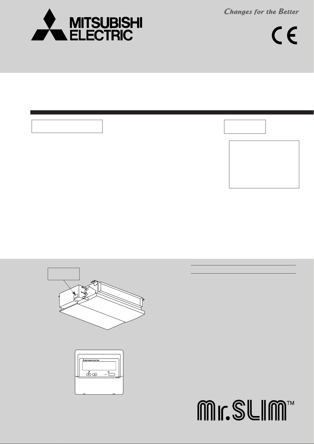
INDOOR UNIT
Indoor unit
[Model names] [Service Ref.]
SEZ-KC25VA SEZ-KC25VA.W
SPLIT-TYPE, HEAT PUMP AIR CONDITIONERS
WIRED REMOTE
CONTROLLER
ON/OFF
TEMP.
Ceiling Concealed
Series SEZ
R410A
Model name
indication
Note :
•This manual does not cover
outdoor units.When ser vicing
outdoor units, please refer
to the service manual
No.OC322 together with this
manual.
Page 2
2
1
PART NAMES AND FUNCTIONS
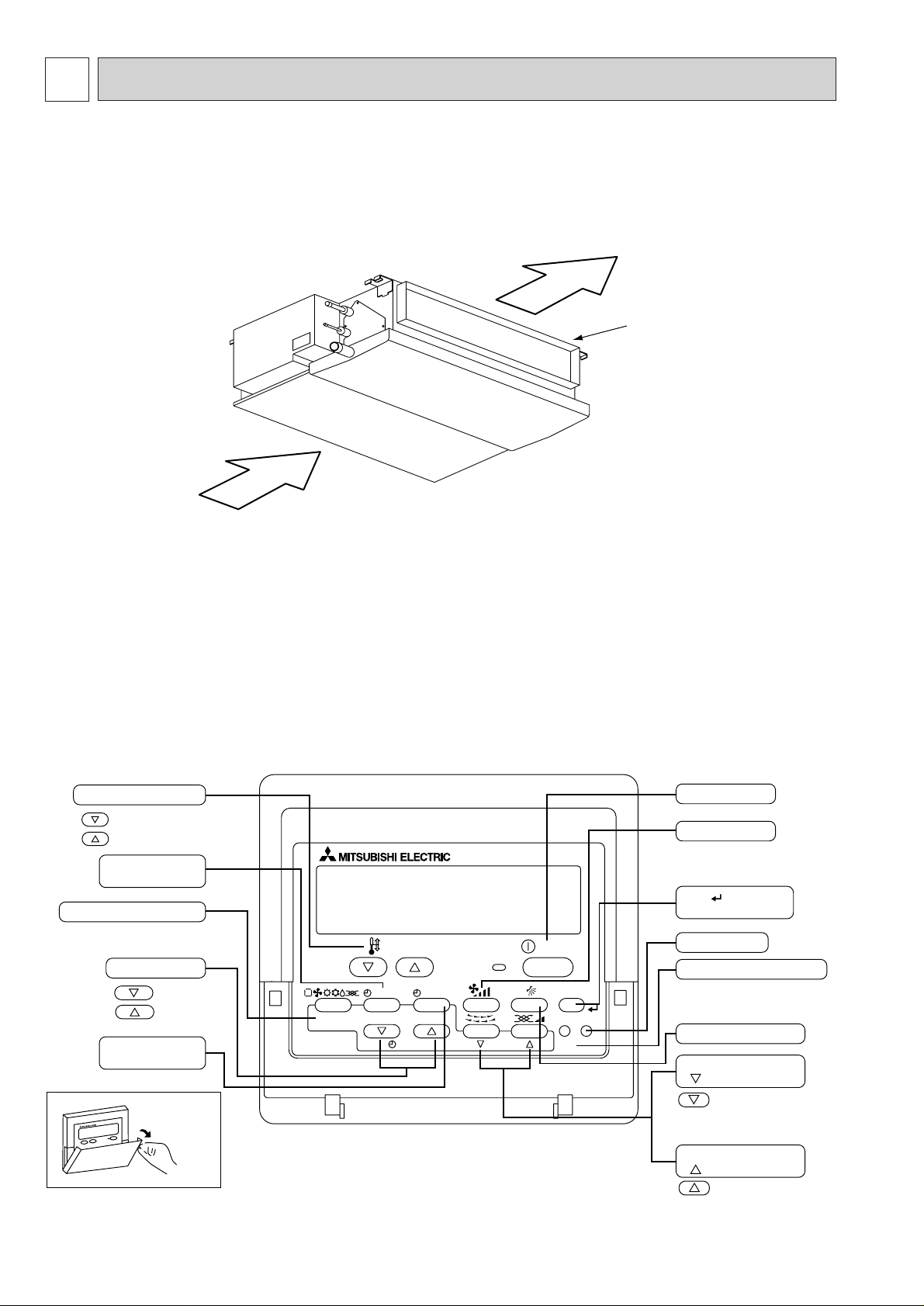
Indoor Unit
SEZ-KC25VA.W
Air outlet duct flange
Air outlet
Air inlet
● Operation buttons
PAR-21MAA
ON/OFF
FILTER
CHECK
OPERATION
CLEAR
TEST
TEMP.
MENU
BACK DAY
MONITOR/SET
CLOCK
ON/OFF
Set Temperature buttons
Down
Up
Timer Menu button
(Monitor/Set button)
Mode button (Return button)
Set Time buttons
Back
Ahead
Timer On/Off button
(Set Day button)
Opening the
door.
Start/Stop button
Fan Speed button
Filter button
(<return sign> button)
Test Run button
Service button (Clear button)
Airflow Up/Down button
Louver button
(
Operation button)
To preceding operation
number.
Ventilation button
(
Operation button)
To next operation number.
On the controls are set, the same operation mode can be repeated by simply pressing the ON/OFF button.
Wired remote controller
Page 3
3
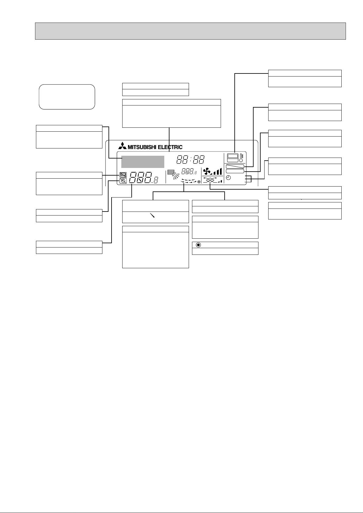
● Display
For purposes of this explanation,
all parts of the display are shown
as lit. During actual operation, only
the relevant items will be lit.
˚F˚C
˚F˚C
ERROR CODE
AFTER
TIMER
TIME SUN MON TUE WED THU FRI SAT
ON
OFF
Hr
AFTER
FILTER
FUNCTION
ONLY1Hr.
WEEKLY
SIMPLE
AUTO OFF
Identifies the current operation
Shows the operating mode, etc.
* Multilanguage display is sup-
ported.
“Centrally Controlled” indicator
Indicates that operation of the remote controller has been prohibited by a master controller.
“Timer Is Off” indicator
Indicates that the timer is off.
Temperature Setting
Shows the target temperature.
Day-of-Week
Shows the current day of the week.
Time/Timer Display
Shows the current time, unless the simple or Auto Off
timer is set.
If the simple or Auto Off timer is set, shows the time
remaining.
“Sensor” indication
Displayed when the remote controller
sensor is used.
“Locked” indicator
Indicates that remote controller buttons have been locked.
“Clean The Filter” indicator
Comes on when it is time to clean the
filter.
Timer indicators
The indicator comes on if the corresponding timer is set.
Up/Down Air Direction indicator
The indicator shows the direction of the outcoming airflow.
“One Hour Only” indicator
Displayed if the airflow is set to
weak and downward during COOL
or DRY mode. (Operation varies
according to model.)
The indicator goes off after one
hour, at which time the airflow direction also changes.
Room Temperature display
Shows the room temperature.
Louver display
Indicates the action of the swing
louver. Does not appear if the
louver is stationary.
(Power On indicator)
Indicates that the power is on.
Fan Speed indicator
Shows the selected fan speed.
Ventilation indicator
Appears when the unit is running in
Ventilation mode.
Caution
● Only the Power display lights when the unit is stopped and power supplied to the unit.
● When power is turned ON for the first time the (Centrally controlled) display appears to go off momentarily but this is not a
malfunction.
● “NOT AVAILABLE” is displayed when the Air speed button are pressed.This indicates that this room unit is not equipped with
the fan direction adjustment function and the louver function.
● When power is turned ON for the first time, it is normal that “PLEASE WAIT” is displayed on the room temperature indication
(For max. 2minutes). Please wait until this “PLEASE W AIT”indication disappear then start the operation.
Page 4
4
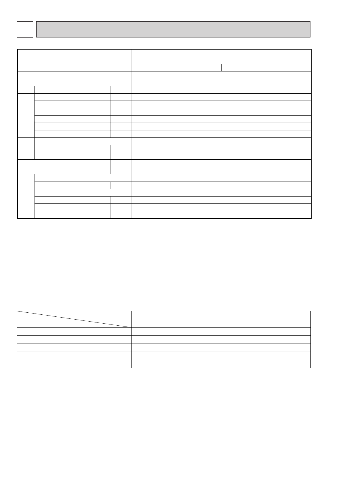
2
SPECIFICATIONS
SEZ-KC25VA.W
Indoor model
Function
Power supply
Single phase
230V , 50Hz
474/288
10
0.45
60
—
97
0.28
CRC4417BB
WHT-BLK : 261 BLK-BLU : 475
YLW-BRN : 294
790✕225✕550
19
1
36/25
2
10
10
10
Cooling
Heating
Air flow (High/Low)
Power outlet
Running current ✽1
Power input Rated frequency
Auxiliary heater
Power factor ✽1
Fan motor current ✽1
Model
Winding
resistance (at20:)
Dimensions W✕H✕D
Weight
Air direction
Sound level (High/Low)
Fan speed regulator
Thermistor RT11 (at 25:)
Thermistor RT12 (at 25:)
Thermistor RT13 (at 25:)
K /h
A
A
W
A(kW)
%
A
Ω
mm
kg
dB(A)
kΩ
kΩ
kΩ
Electrical
data
Fan
motor
Special remarks
Capacity
NOTE :Test conditions are based on ISO 5151
Cooling : Indoor D.B. 27
: W.B. 19:
Outdoor D.B. 35: W.B. 24:
Heating : Indoor D.B. 20: W.B. 5:
Outdoor D.B. 7: W.B. 6:
Refrigerant piping length (one way): 5m
✽1 Measured under rated operating frequency.
1.5+ 440V
250V 6.3A
ERZV10D471
TO OUTDOOR UNIT : 3P TO WIRED REMOTE CONTROLLER : 2P
135:i5:
INDOOR UNIT
Item
Model
Indoor fan capacitor
Fuse
Varistor
Terminal block
Indoor fan motor thermal fuse
SEZ-KC25VA.W
(C)
(FUSE)
(ZNR)
(TB)
Specifications and rating conditions of main electric parts
Page 5
5
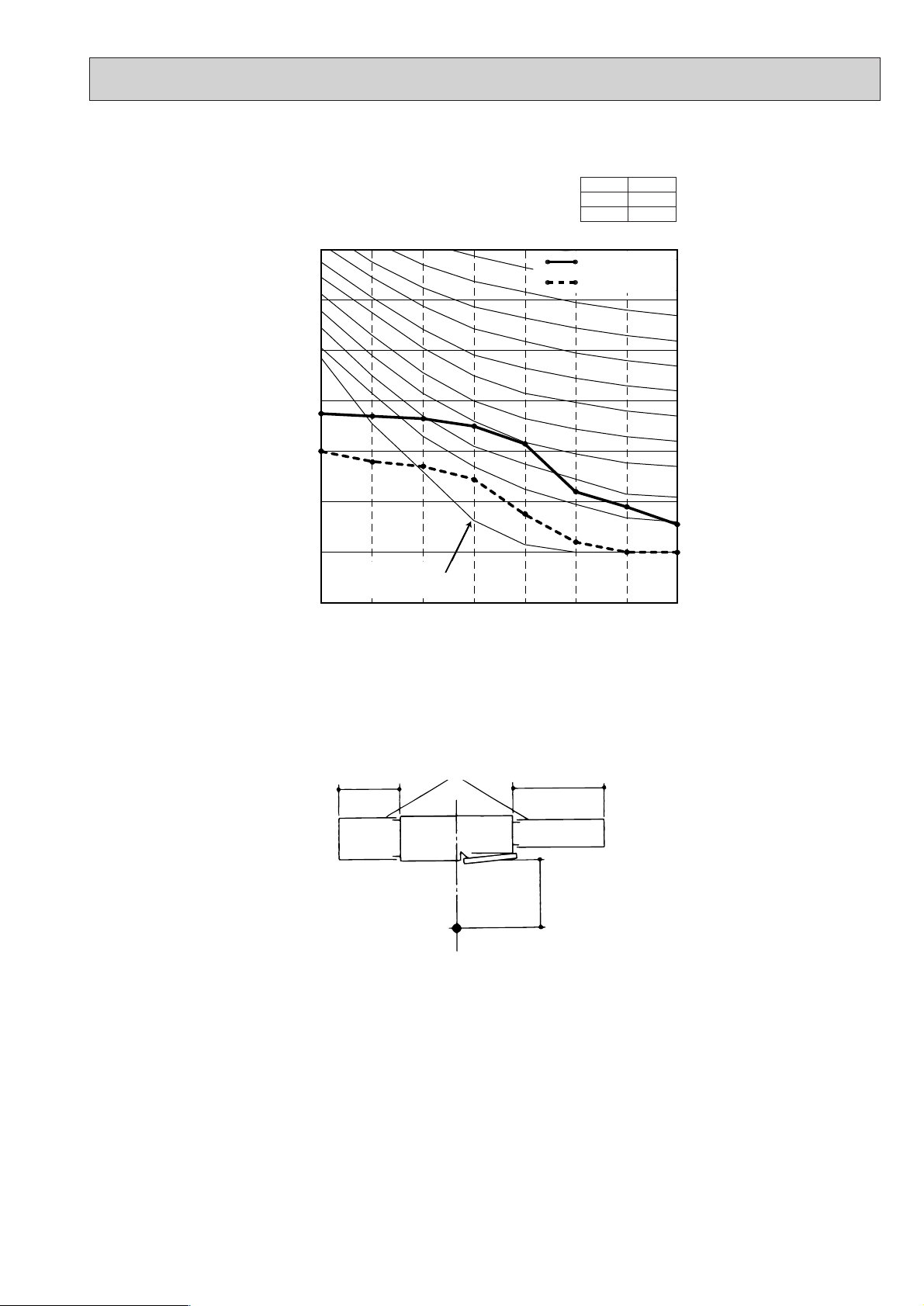
NOISE CRITERION CURVES
2m
Aux.duct
1m
1.5m
Measurement location
NOTE:The sound level is measured in an anechoic room where echoes are few, when compressor stops. The sound
may be bigger than displayed level under actual installation condition by surrounding echoes.The sound level
can be higher by about 2 dB than the displayed level during cooling and heating operation.
SEZ-KC25VA.W
NOTCH
Hi
Lo
<50Hz>
SPL(dB)
36
25
70
60
50
40
30
20
10
OCTAVE BAND PRESSURE LEVEL (dB) 0dB = 20µPa
Appro
Approximate minimum
audible limit on continuous noise
0
63 125 250 500 1000 2000 4000 8000
OCTAVE BAND CENTER FREQUENCIES (Hz)
High speed
Low speed
NC60
NC50
NC40
NC30
NC20
Page 6
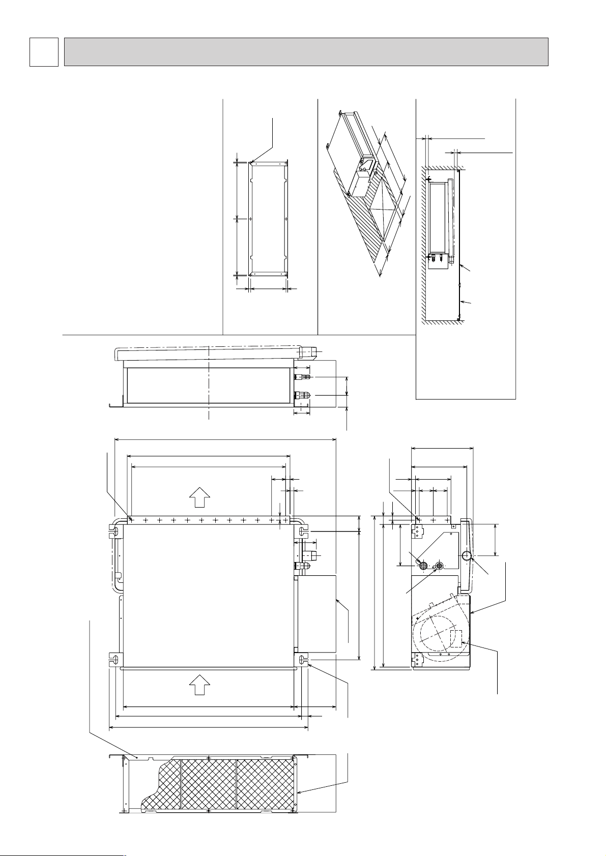
Make the access door at the appointed position properly
for service maintenance.
Ceiling surfaceAccess door
Required space for service and maintenance
Lifting plate
(4-14x30)
Air filter
80
Control box
T erminal bed
(Power source)
Bottom plate
23 664(Lifting bolt pitch)
710
The part air intake duct is attached.(✻3)
(When the air intake duct is used)
610
50
150
790
582
204.5
42.5
30
225(✻2)
15
148
13.55050
510
14127
56.5
(52)
(57)
129
55301 301
189
Detailed chart around the air intake duct frange(✻3)
(Duct and frange should be supplied in the field)
550(✻1)
More than 20mm
More than 20mm
6- ø 3hole
55
50X11=550
16
2X12- ø 3hole
14
459(Lifting bolt pitch)
15
113
Air outlet
Air inlet
450
50~150
300
450
2X3- ø 3hole
25
500
50~150
1
2
3
Note 1. Use M10 screw for the lifting bolt (field supply).
2. Keep the service space for the maintenance from the bottom
when the heat exchanger is cleaned.
3. The direction of air intake can be changed from the bottom to
the rear by attaching the bottom plate to the air intake side.
4. Drain Pan is changeable from right and left.
5. The dimension is changed, in case the optional long-life filter
is attached.
Rear Air-Intake spec. :Depth is increased by 30mm(✻1)
Bottom Air-Intake spec. :Height is increased by 30mm(✻2)
Refrigerant piping flare connection
(gas ø 9.52 copper tube):LP ········1
Refrigerant piping flare connection
(liquid ø 6.35 copper tube):HP ········2
Drain piping connection R1 (External thread) ········3
6
OUTLINES AND DIMENSIONS
3
SEZ-KC25VA.W
Page 7
7
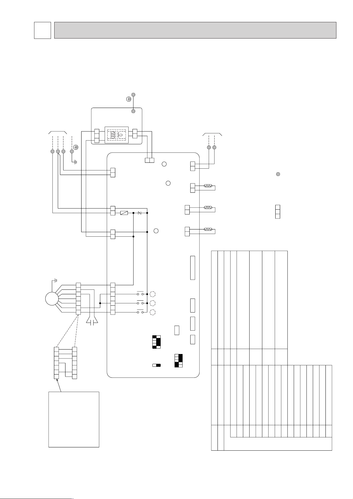
4
WIRING DIAGRAM
SEZ-KC25VA.W
12
213
131313
1
2
312 4567
1234675
2121
2121
6457321
6457321
TO OUTDOOR UNIT
TH2
TRANS
AC220-240V
CNSK(RED)
DC13.1V
CN2S(WHT)
P.B.
BLU
(CONTROL)
CN3C
ORN
(POWER)
CND
RED
(POWER BOARD)
CNDK
S1S2S3
I.B.
TB4
FUSE
ZNR
X6 X5 X4
WHT
(POWER
BOARD)
CN2D
WHT
(FAN)
FAN
LED1
LED2
LED3
CN32
CN2L
CN51 CN41
CN90
BLK
(2 PHASE)
CN29
RED
(INTAKE)
CN20
WHT
(LIQUID)
CN21
BLU
(REMOCON)
CN22
X6 X5 X4
TH1TH5
1
2
SW2
12345
ON
OFF
5432
OFF
ON
1
SW3
OFF
ON
1
SWE
TB15
TO MA-REMOTE
CONTROLLER
DC8.7-13V
LED1
FUSE
CN90
ZNR
X6
X5
X4
VARISTOR
RELAY (FAN MOTOR HI)
RELAY (FAN MOTOR Lo)
SWE
SW3
RELAY (FAN MOTOR LL)
SWITCH (EMERGENCY OPERATION)
SWITCH (MODE SELECTION)
SW2
LED3
LED2
SWITCH (CAPACITY CODE)
TRANSMISSION (INDOOR-OUTDOOR)
POWER SUPPLY (I.B.)
POWER SUPPLY (I.B.)
FUSE (6.3A)
CN51
CN41
CN32
CN2L
CONNECTOR (WIRELESS)
CENTRALLY CONTROL
CONNECTOR (HA TERMINAL-A)
CONNECTOR (REMOTE SWITCH)
CONNECTOR (LOSSNAY)
I.B.
P.B.
SYMBOL
INDOOR CONTROLLER BOARD
NAME
INDOOR POWER BOARD
SYMBOL
C
MF FAN MOTOR
CAPACITOR (FAN MOTOR)
NAME
TB4
TERMINAL BLOCK (INDOOR/OUTDOOR CONNECTING LINE)
TB15
TERMINAL BLOCK (REMOTE CONTROLLER
TRANSMISSION LINE)
TH1
INT AKE AIR TEMP. THERMIST OR
(0˚C/15kΩ. 25˚C/5.2kΩ DETECT)
TH2
PIPE TEMP. THERMIST OR/LIQUID
(0
˚C/15kΩ. 25˚C/5.2kΩ DETECT)
TH5
COND./EVA. TEMP. THERMISTOR
(0
˚C/15kΩ. 25˚C/5.2kΩ DETECT)
C
MF
INSERT
BLU
The motor connector is
connected with 230V,240V
power at factory shipment.
If 220V power is used,
Insert the attachment.
Color/Power source
WHT/230,240V
BLU/220V
NOTES:1.Since the outdoor side electric wiring may change be sure to
check the outdoor unit electric wiring for servicing.
2.Indoor and outdoor connecting wires are made with polarities, make
wiring matching terminal numbers (S1,S2,S3).
3.Symbols used in wiring diagram above are,
: Connector, : Terminal.
4.The wiring between MA-REMOTE CONTROLLER and TB15 is
included in the package.
Page 8

REFRIGERANT SYSTEM DIAGRAM
5
8
Gas pipe
SEZ-KC25VA.W
ø 9.52<3/8>
mm<in>
Liquid pipe
ø 6.35<1/4>
Capacity
Item
Refrigerant flow in cooling
Refrigerant flow in heating
Pipe temperature
thermistor/liquid
(TH2)
Condenser/evaporator
temperature thermistor
(TH5)
Strainer (#50 mesh)
Heat exchanger
Intake air temperature thermistor TH1
Gas pipe
Flared joints
SEZ-KC25VA.W
Page 9

9
6
TROUBLESHOOTING
6-1. Cautions on troubleshooting
(1) Before troubleshooting, check the followings:
1 Check the power supply voltage.
2 Check the indoor/outdoor connecting wire for mis-wiring.
(2) Take care the followings during servicing.
1 Before servicing the air conditioner, be sure to first turn off the remote controller to stop the main unit, and then turn
off the breaker.
2 When removing the indoor controller board, hold the edge of the board with care NOT to apply stress on the
components.
3 When connecting or disconnecting the connectors, hold the housing of the connector. DO NOT pull the lead wires.
˚C
˚C
SIMPLE
PAR-21MAA
ON/OFF
FILTER
CHECK
OPERATION
CLEAR
TEST
TEMP.
MENU
BACK DAY
MONITOR/SET
CLOCK
ON/OFF
B
C
A
E D
6-2. Self-check function
Wired remote controller
(1) Tur n on the power.
(2) Press the [CHECK] button twice.
(3) Set refrigerant address with [TEMP] button
if system control is used.
(4) Press the [ON/OFF] button to stop the
self-check.
AA
CHECK button
BB
Refrigerant address
CC
TEMP button
DD
IC : Indoor unit
OC : Outdoor unit
EE
Check code
1 Check code Symptom Remark
P1 Intake sensor error
P2 Pipe (TH2) sensor error
P9 Pipe (TH5) sensor error
E6,E7 Indoor/outdoor unit communication error
P4 Drain sensor error
P5 Drain pump error
P6 Freeing/Overheating safeguard operation
EE Communication error between indoor and outdoor units
P8 Pipe temperature error
E0, E3~E5 Remote controller transmission error
E1, E2 Remote controller control board error
Fb Indoor unit control system error (memory error, etc.)
E9 Indoor/outdoor unit communication error (Transmitting error) (Outdoor unit)
UP Compressor overcurrent interruption
U3,U4 Open/short of outdoor unit thermistors
UF Compressor overcurrent interruption (When compressor locked)
U2 Abnormal high discharging temperature/49C worked/insufficient refrigerant
U1,Ud Abnormal high pressure (63H worked)/Overheating safeguard operation
U5 Abnormal temperature of heat sink
U8 Outdoor unit fan safeguard stop
U6 Compressor overcurrent interruption/Abnormal of power module
U7 Abnormality of super heat due to low discharge temperature
U9,UH Abnormality such as overvoltage or voltage shortage and abnormal synchronous signal to main circuit
/Current sensor error
Others Other errors (Refer to the technical manual for the outdoor unit.)
For details, check the LED display
of the outdoor controller board.
As for outdoor unit, refer to
service manual OC322.
• On wired remote controller.
1 Check code displayed in the LCD.
• For description of each check code, refer to the following table.
Page 10

6-3.Test point diagram
6-3-1. Indoor power board
SEZ-KC25VA.W
10
CNSK
Connect to the indoor controller board
(CNDK)
Between
11
to 33220-240V AC
CN2S
Connect to the indoor controller board (CN2D)
Between
11
to
33
12.6-13.7V DC (Pin11(+))
Page 11

11
6-3.Test point diagram
6-3-2. Indoor controller board
SEZ-KC25VA.W
FAN
Fan motor output
CNDK
Connect to the indoor
power board (CNSK)
(220~240V AC)
FUSE
(6.3A 250V)
CND
Power
supply input
(220~240V AC)
SWE
Emergency operation
SW2
Capacity setting
Jumper connector
J11~J15
Unit setting
CN2L
Connector
(LOSSNAY)
CN51
Centrally control
CN29
Condenser/evaporator
temperature thermistor
(TH5)
CN21
Pipe temperature
thermistor/Liquid
(TH2)
CN20
Room temperature
thermistor (TH1)
CN22
Remote controller
connecting wire
(10.4~14.6V DC)
LED3
Transmission
(Indoor/outdoor)
LED2
Power supply
(R.B)
LED1
Power supply
(I.B)
CN2D
Connector to the indoor
power board (CN2S)
(12.5~13.7V DC)
CN3C
Transmission
(Indoor/outdoor)
(0~24V DC)
SW3
Mode selection
}
}
Non polarity
+
–
+
–
CN41
Connector
(HA terminal-A)
Page 12

12
6-4.Trouble criterion of main parts
SEZ-KC25VA.W
Intake air temperature
thermistor (TH1)
Condenser/evaporator
temperature thermistor (TH5)
Measure the resistance with a tester.
(Part temperature 10°C ~ 30°C)
Pipe temperature
thermistor/liquid (TH2)
Indoor fan motor
(MF)
Check method and criterion
Part name
Normal
8kΩ~20kΩ
Abnormal
Opened or short-circuited
Measure the resistance between the terminals using a tester. (at 20˚C)
Motor terminal
or
Relay connector
Normal Abnormal
Open or short
White-Black
261
Ω
White-Brown
White-Yellow
White-Blue
294
Ω
389
Ω
475
Ω
White
Orange
Red
Black
Brown
Yellow
Blue
1
2
4
7
5
6
Protector
Relay connector
3
Page 13

13
DISASSEMBLY PROCEDURE
7
7-1. CONTROL BOX
OPERATING PROCEDURE PHOTOS
1.Removing the control box cover
(1) Remove the fixing screws (two) of the control box (A), and
remove the cover. (Fig. 1)
*At this stage, the following servicing is possible.
1 Connection check of the lead wires (listed below) which
are connected to the controller board.
• Power supply (TB4) lead wire.
• Fan motor (MF) lead wire.
• Intake air sensor (TH1) lead wire
• Liquid
• Cond/Eva piping sensor (TH5) lead wire
piping sensor (TH2) lead wire
2
Control board (I.B.) exchange
3
4
Intake air sensor (TH1) exchange
Terminal block (TB4, TB15) exchange
Be careful on removing heavy parts.
fig.1
fig.2
(A)
Page 14

14
7-2. FAN and FAN MOTOR
OPERATING PROCEDURE PHOTOS
Be careful on removing heavy parts.
fig.3
fig.5
1.Removing the fan casing and sirocco fan.
(1) Remove the bottom plate B. (fixing screws : six) (Fig. 3)
(2) Remove the fixing screws (three) of the fan cover, and turn
it in direction of arrow. (Fig. 4)
(3) Remove the fixing screws (two) of the fan cover , and loosen
the set screw of the sirocco fan, and remove the fan cover
and sirocco fan. (Fig. 5)
2.Removing the fan motor.
(1) Remove the control box. (fixing screws : two) (Fig. 7)
(2) Move the control box to place that is not block operation.
(Fig. 8)
(3) Remove the fan motor cable connector in the control box,
and remove the screws of the fixing plate. (Fig. 9)
fig.7
fig.9
fig.4
fig.6
fig.8
Fan cover
Bottom plate B
Set screw
Fan motor
cable connector
Page 15

15
fig.10
fig.11
OPERATING PROCEDURE PHOTOS
1.Removing the drain pan.
(1) Remove the fixing screw (one) of the drain pan. (Fig. 10).
(2) Slide the drain pan in the order of arrow ①,➁,③, and remove
the drain pan. (Fig. 11)
Be careful on removing heavy parts.
7-3. DRAIN PAN
Drain pan
Drain pan
1
2
3
Page 16

16
OPERATING PROCEDURE PHOTOS
(1) Remove the drainpan with procedure 7-3.
(2) Remove the bottom plate A (fixing screws : six), and remove
the plate.(Fig. 12)
(3) Remove the thermistors from the thermistor holders which
are installed on the piping.(Fig. 13)
(liquid piping : fine piping )
fig.12
fig.13
Be careful on removing heavy parts.
1.Removing the thermistors.
7-4.THERMISTOR (Liquid piping temperature detection)
Bottom plate A
Thermistor
Page 17

17
7-5. HEAT EXCHANGER
OPERATING PROCEDURE PHOTOS
1.Removing the heat exchanger.
(1) Remove the drainpan with procedure 7-3.
(2) Remove the bottom plate A with procedure 7-4.
(3) Remove the heat exchanger cover.(fixing screws : four)
(Fig. 14)
(4) Remove the heat exchanger.(fixing screws : three)
(Fig. 15),(Fig. 16)
fig.14
fig15
fig.16
Be careful on removing heavy parts.
Heat exchanger cover
Page 18

18
101
R61 Y85 481 Heat exchanger ass'y 1 W273547
G06
102 R61 Y18 201 Thermistor (2phase) TH5 1 W848734G11
103 R61 Y19 201 Thermistor (liquid) TH2 1 W848734G10
104 R61 Y13 661 Bottom plate A 1 W635907G02
105 R61 Y14 661
Bottom plate B 1 W877415G02
106 R61 Y10 529 Drain pan 1 W877416G01
107 R61 Y06 501 Filter 1 W634781H01
108 R61 151 326 Lifting plate 4 W398770H02
Dwg. No. Price
No.
Part No. Part Name Spec.
-KC25VA
107
108
105
106
104
101.102.103
PARTS LIST
8
EXTERNAL PARTS
SEZ-KC25VA.W
Page 19

19
201
R61 Y14 140 Fan stand 1 W267214G01
202 R61 370 130 Motor support 1 W234925H06
203 R61 220 044 Rubber bush 2 W837244H01
204 R61 652 131 Fixing plate 2 W353715H01
205
R61 Y38 221
Motor P20L
CRC4417BB1ø23W<MF>
1 P714880X01
206
R61 Y16 118 Fan cover 1 W879404G03
207 R40 045 103 Sirocco fan ass'y 1 W234904G01
Dwg. No. Price
No.
Part No. Part Name Spec.
-KC25VA
BLOWER PARTS
SEZ-KC25VA.W
201
202
203
204203 205
206
207
Page 20

301
R61 Y08 715 Terminal bed <3P(S1,S2,S3)> 1 P436157X01
302 R61 435 246 Terminal bed <2P(1,2)>
440V 1.5µF
Intake air
1 A73S950H02
303 R61 Y65 281 Controller board ass'y
1 P785032X01
304 R61 R92 281 Power supply board ass'y 1 P785020X01
305 R61 Y01 287 Thermistor 1 W891304G16
306 R61 Y14 252 Capacitor 1 P412234X01
Dwg. No. Price
No.
Part No. Part Name Spec.
-KC25VA
306
303
304
305
301
302
S1
1
2
S2
S3
FAN
CNDK
CND
CN3C
CN2D
CN20
CN22
20
CONTROL BOX PARTS
SEZ-KC25VA.W
Page 21

21
Applied unit
SEZ-KC25VA.W
Models Pipe length
Pipe size O.D.mm (in.)
Cross-section A-Gas
9.52
(3/8)
6.35
(1/4)
27
21
B-liquid
Insulation
CD
3m
5m
7m
10m
MAC-440PI
MAC-441PI
MAC-442PI
MAC-443PI
9
OPTIONAL PARTS
9-1. REFRIGERANT PIPES
The air conditioner has flared connections.
Please use the optional extension pipe as follows.
Page 22

MEE04K350
Issued in Mar. 2005
Printed in Japan
New publication, effective Mar. 2005.
Specifications subject to change without notice.
TM
HEAD OFFICE: MITSUBISHI DENKI BLDG., 2-2-3, MARUNOUCHI, CHIYODA-KU, TOKYO 100-8310, JAPAN
 Loading...