

Page 1
Air-Conditioners
SEZ-KA35, KA50, KA60VA
OPERATION MANUAL
For safe and correct use, please read this operation manual thoroughly before operating the air-conditioner unit.
BEDIENUNGSHANDBUCH
Zum sicheren und einwandfreien Gebrauch der Klimaanlage dieses Bedienungshandbuch vor Inbetriebnahme
gründlich durchlesen.
MANUEL D’UTILISATION
Pour une utilisation correcte sans risques, veuillez lire le manuel d’utilisation en entier avant de vous servir du
climatiseur.
BEDIENINGSHANDLEIDING
Voor een veilig en juist gebruik moet u deze bedieningshandleiding grondig doorlezen voordat u de
airconditioner gebruikt.
MANUAL DE INSTRUCCIONES
Lea este manual de instrucciones hasta el final antes de poner en marcha la unidad de aire acondicionado
para garantizar un uso seguro y correcto.
ISTRUZIONI DI FUNZIONAMENTO
Leggere attentamente questi istruzioni di funzionamento prima di avviare l’unità, per un uso corretto e sicuro
della stessa.
E°XEIPI¢IO O¢H°IøN XPH™Eø™
°И· ·ЫК¿ПВИ· О·И ЫˆЫЩ‹ ¯Ъ‹ЫЛ, ·Ъ·О·ПВ›ЫЩВ ‰И·‚¿ЫВЩВ ЪФЫВ¯ЩИО¿ ·˘Щfi ЩФ ВБ¯ВИЪ›‰ИФ ¯Ъ‹ЫВˆ˜ ЪИУ ı¤ЫВЩВ ЫВ
ПВИЩФ˘ЪБ›· ЩЛ МФУ¿‰· ОПИМ·ЩИЫМФ‡.
MANUAL DE OPERAÇÃO
Para segurança e utilização correctas, leia atentamente o manual de operação antes de pôr a funcionar a
unidade de ar condicionado.
FOR USER
FÜR BENUTZER
POUR L’UTILISATEUR
VOOR DE GEBRUIKER
Nederlands
PARA EL USUARIO
PER L’UTENTE
°π∞ ∆√¡ Ã∏™∆∏
PARA O UTILIZADOR
Português
English
Deutsch
Français
Español
Italiano
∂ППЛУИО¿
DRIFTSMANUAL
Läs denna driftsmanual noga för säkert och korrekt bruk innan luftkonditioneringen används.
FÖR ANVÄNDAREN
Svenska
Page 2
Contents
1. Safety Precautions ...................................................................................................................................................................... 2
2. Operation..................................................................................................................................................................................... 3
3. Care and cleaning ..................................................................................................................................................................... 13
4. Troubleshooting ......................................................................................................................................................................... 13
5. Installation, relocation and inspection ....................................................................................................................................... 14
6. Specifications ............................................................................................................................................................................ 15
1. Safety Precautions
s Before installing the unit, make sure you read all the “Safety precautions”.
s The “Safety precautions” provide very important points regarding safety. Make sure you follow them.
s Please report to or take consent by the supply authority before connection to the system.
Symbols used in the text
Warning:
Describes precautions that should be observed to prevent danger of injury or death to the user.
Caution:
Describes precautions that should be observed to prevent damage to the unit.
Symbols used in the illustrations
: Indicates an action that must be avoided.
: Indicates that important instructions must be followed.
: Indicates a part which must be grounded.
: Indicates that caution should be taken with rotating parts.
: Indicates that the main switch must be turned off before servicing.
: Beware of electric shock.
: Beware of hot surface.
Warning:
Carefully read the labels affixed to the main unit.
Warning:
• The unit should not be installed by the user. Ask the dealer or an authorized company to install the unit. If the unit is installed improperly,
water leakage, electric shock or fire may result.
• Do not stand on, or place any items on the unit.
• Do not splash water over the unit and do not touch the unit with wet hands. An electric shock may result.
• Do not spray combustible gas close to the unit. Fire may result.
• Do not place a gas heater or any other open-flame appliance where it will be exposed to the air discharged from the unit. Incomplete
combustion may result.
• Ventilate the room if refrigerant leaks during operation.
If the refrigerant comes in contact with a flame, poisonous gases will be released.
• Do not remove the front panel or the fan guard from the outdoor unit when it is running. You could be injured if you touch rotating, hot or
high-voltage parts.
• Never insert fingers, sticks etc. into the intakes or outlets, otherwise injury may result, since the fan inside the unit rotates at high speed.
• If you detect odd smells, stop using the unit, turn off the power switch and consult your dealer.
• This air conditioner is NOT intended for use by children or infirm persons without supervision.
• Young children should be supervised to ensure that they do not play with the air conditioner.
Caution:
• Do not use any sharp object to push the buttons, as this may damage the remote controller.
• Never block or cover the indoor or outdoor unit’s intakes or outlets.
Disposing of the unit
When you need to dispose of the unit, consult your dealer. If pipes are removed incorrectly, refrigerant (fluorocarbon gas) may blow out and come into
contact with your skin, causing injury. Releasing refrigerant into the atmosphere also damages the environment.
2
Page 3
2. Operation
˚C
˚C
SIMPLE
PAR-21MAA
ON/OFF
FILTER
CHECK
OPERATION
CLEAR
TEST
TEMP.
MENU
BACK DAY
MONITOR/SET
CLOCK
ON/OFF
1
A
˚C
˚C
SIMPLE
PAR-21MAA
ON/OFF
FILTER
CHECK
OPERATION
CLEAR
TEST
TEMP.
MENU
BACK DAY
MONITOR/SET
CLOCK
ON/OFF
2
B
1
A
˚C
˚C
TIME SUN
PAR-21MAA
ON/OFF
FILTER
CHECK
OPERATION
CLEAR
TEST
TEMP.
MENU
BACK DAY
MONITOR/SET
CLOCK
ON/OFF
2
4
9
1
A
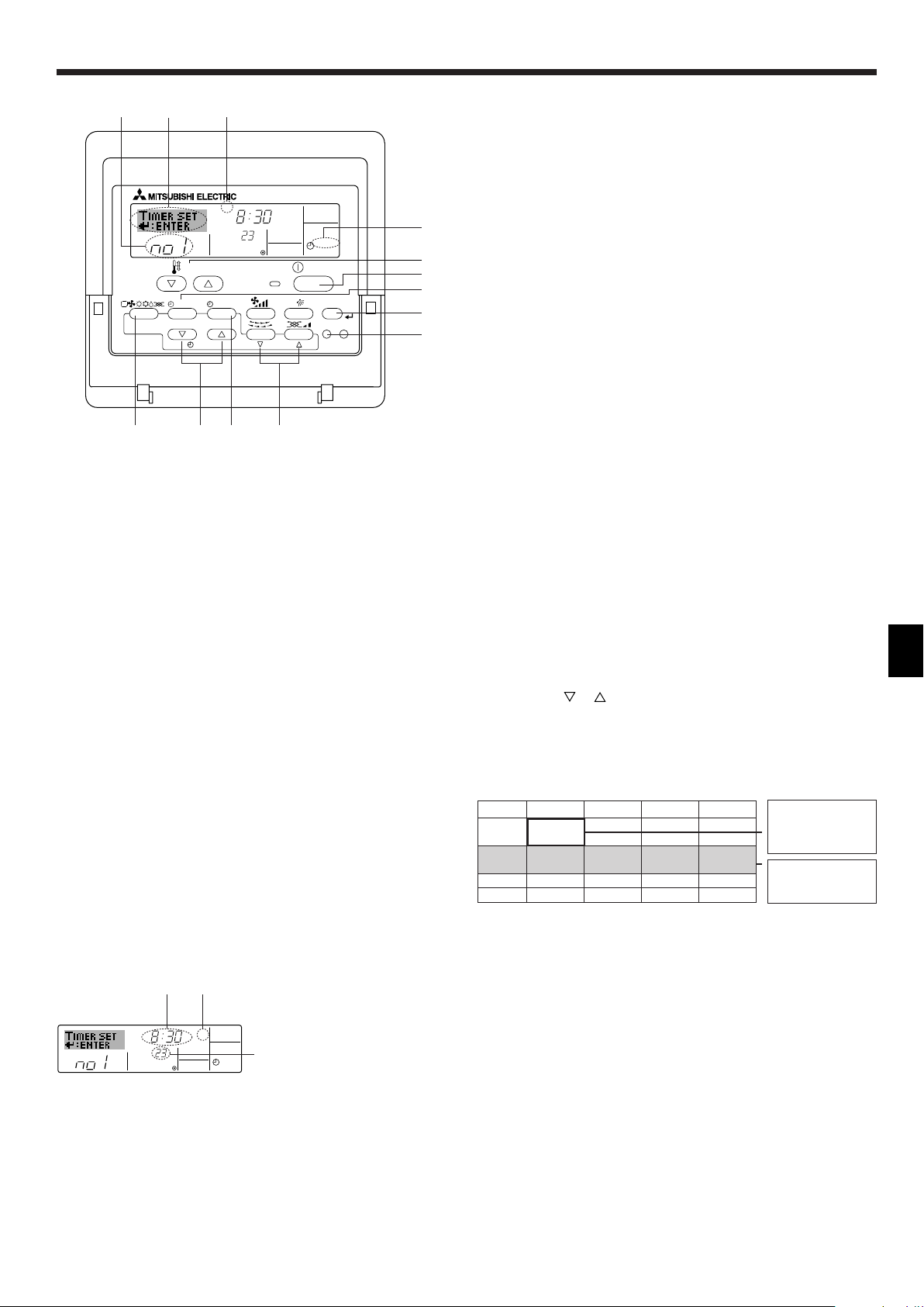
TIME SUN
2
3
4
Day of the Week &
Time display
Day of the Week Setting
Time Setting
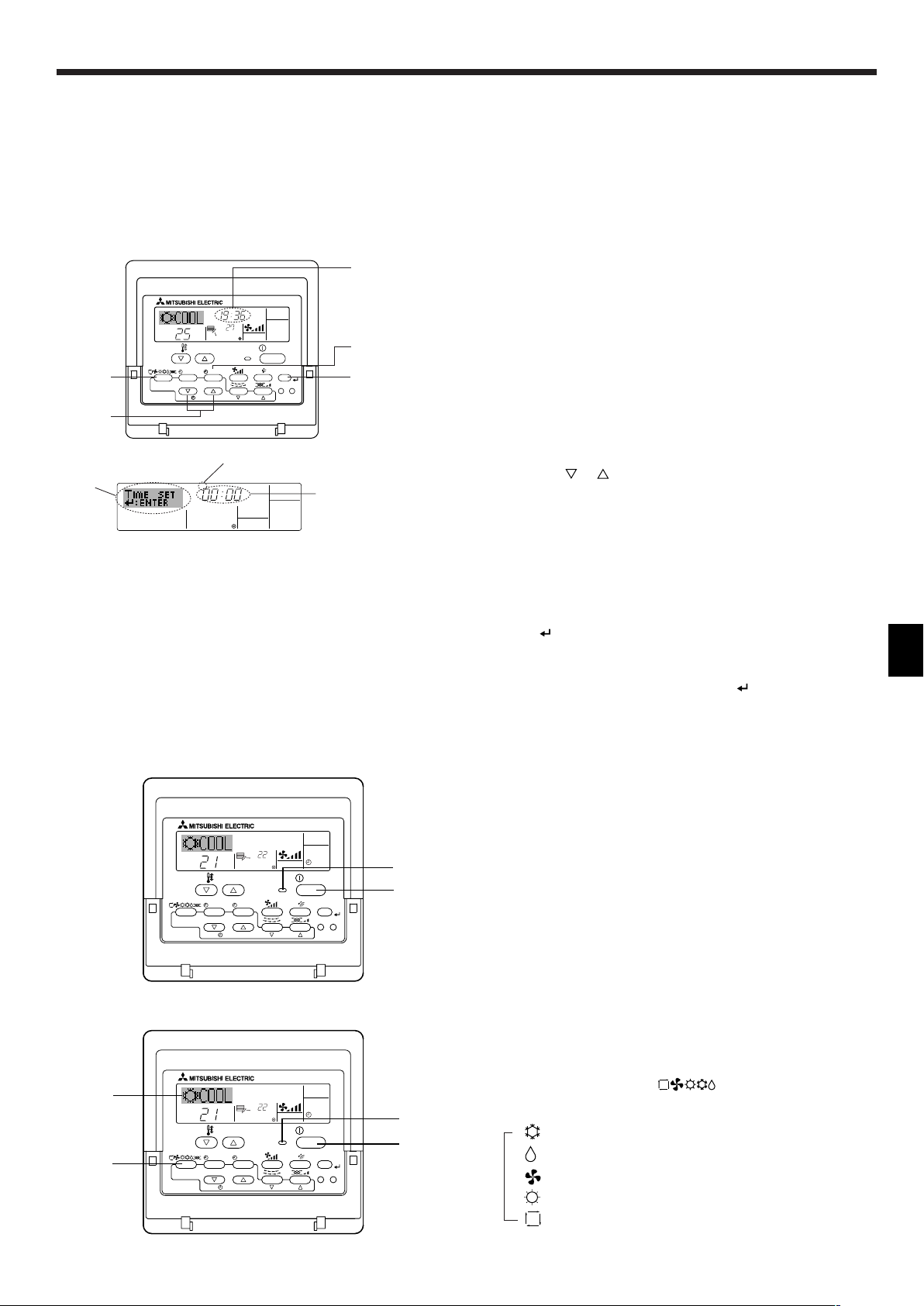
2.1. Description of “AUTO RESTART FUNCTION”
• This unit is equipped with the auto restart function. When the main power is
turned on, the air conditioner will start operation automatically in the same
mode as set with the remote controller before the shutoff of main power.
• If the unit was set to off with the remote controller before the shutoff of
main power, it will remain stopped even after the main power is turned on.
• If the unit was in the TEST RUN before the shutoff of main power, it will
start operation, at main power on, in the same mode as set with the
remote controller before the TEST RUN.
2.2. Setting the day of the week and time
■ Use this screen to change the current day of the week and time setting.
Note:
The day and time will not appear if clock use has been disabled at Function
Selection of remote controller.
ss
sHow to Set the Day of the Week and Time...
ss
1. Press the or Set Time button A to show display 2.
2. Press the Timer On/Off (Set Day) button 9 to set the day.
* Each press advances the day shown at 3 : Sun → Mon → ... → Fri
→ Sat.
3. Press the appropriate Set Time button A as necessary to set the
time.
* As you hold the button down, the time (at 4) will increment first in
minute intervals, then in ten-minute intervals, and then in one-hour
intervals.
4. After making the appropriate settings at Steps 2 and 3, press the
Filter button 4 to lock in the values.
Note:
Your new entries at Steps 2 and 3 will be cancelled if you press the Mode
(Return) button 2 before pressing the Filter
button 4.
5. Press the Mode (Return) button 2 to complete the setting proce-
dure. This will return the display to the standard control screen, where
1 will now show the newly set day and time.
2.3. Switching the unit on/off
• The power supply should not be turned off while the air conditioner is in
use. This can cause the unit to break down.
1 Press the ON/OFF button.
AThe ON indicator should light up.
• Even if you press the ON/OFF button immediately after shutting down
the operation in progress, the air conditioner will not start for about three
minutes. This is to prevent the internal components from being damaged.
• If the operation stops due to a power failure, the unit will not automatically restart until the power has been restored. Press the ON/OFF button to restart.
2.4. Mode select
1 If the unit is off, press the ON/OFF button to turn it on.
AThe ON indicator should light up.
2 Press the operation mode ( ) button and select the opera-
tion mode.
B
s
(COOL) Cooling mode
(DRY) Drying mode
(FAN) Fan mode
(HEAT) Heating mode
(AUTO) Automatic (cooling/heating) mode
3
Page 4
2. Operation
˚C
˚C
SIMPLE
PAR-21MAA
ON/OFF
FILTER
CHECK
OPERATION
CLEAR
TEST
TEMP.
MENU
BACK DAY
MONITOR/SET
CLOCK
ON/OFF
A
1
˚C
˚C
SIMPLE
PAR-21MAA
ON/OFF
FILTER
CHECK
OPERATION
CLEAR
TEST
TEMP.
MENU
BACK DAY
MONITOR/SET
CLOCK
ON/OFF
A
1
TEMP.
Information for multi system air conditioner (Outdoor
unit: MXZ series)
ss
sMulti system air conditioner (Outdoor unit: MXZ series) can con-
ss
nect two or more indoor units with one outdoor unit. According to
the capacity, two or more units can operate simultaneously.
• When you try to operate two or more indoor units with one outdoor unit
simultaneously, one for the cooling and the other for heating, the operation mode of the indoor unit that operates earlier is selected. The other
indoor units that will start the operation later cannot operate, indicating
an operation state.
In this case, please set all the indoor units to the same operation mode.
• There might be a case that the indoor unit, which is operating in
(AUTO) mode. Cannot change over to the operating mode (COOL ↔
HEAT) and becomes a state of standby.
• When indoor unit starts the operation while the defrosting of outdoor
unit is being done, it takes a few minutes (max. about 15 minutes) to
blow out the warm air.
• In the heating operation, though indoor unit that does not operate may
get warm or the sound of refrigerant flowing may be heard, they are not
malfunction. The reason is that the refrigerant continuously flows into it.
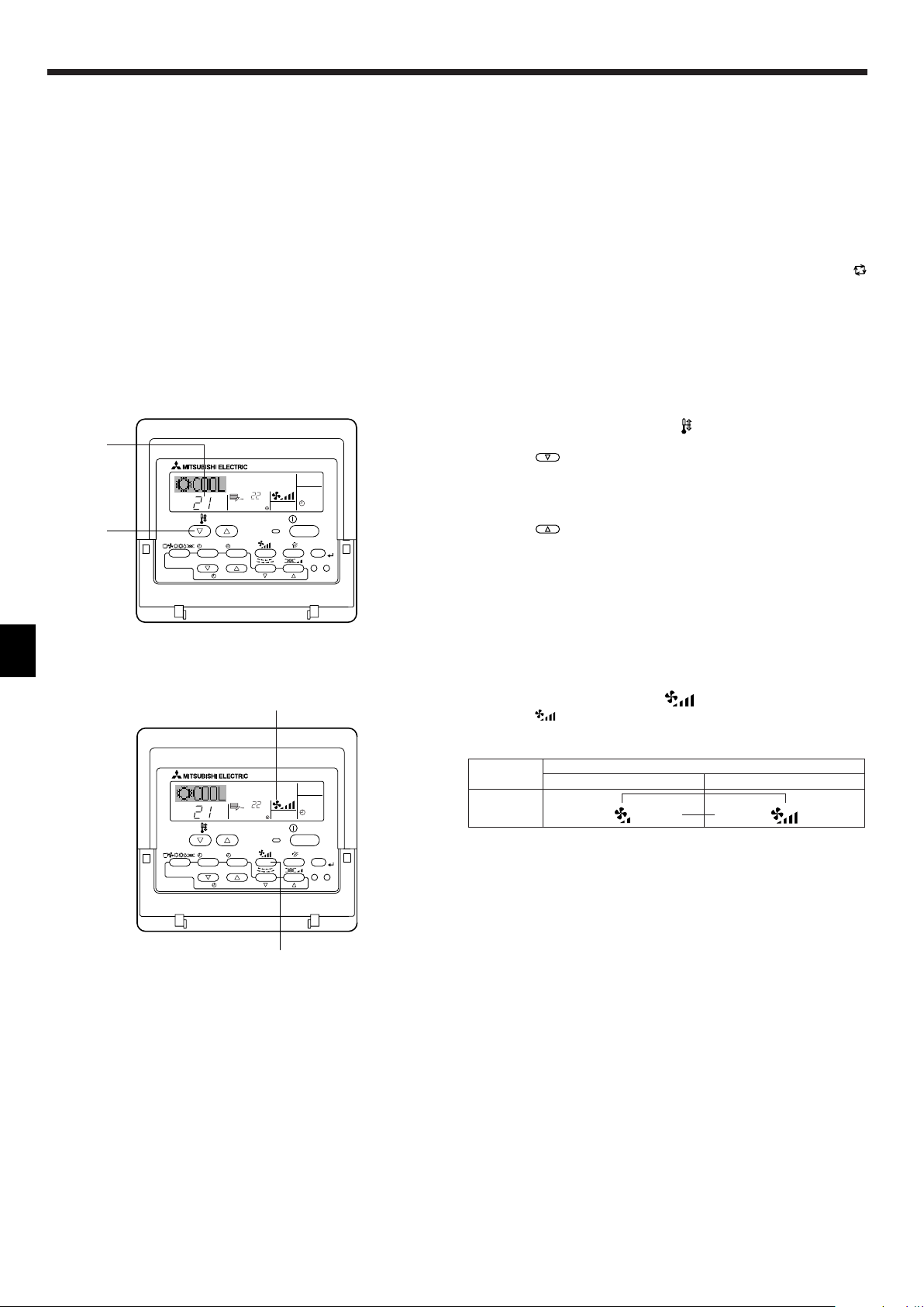
2.5. Selecting a temperature
ss
sTo decrease the room temperature:
ss
1 Press button to set the desired temperature.
AThe selected temperature is displayed.
• Each time you press the button, the temperature value decreases by 1 °C.
ss
sTo increase the room temperature:
ss
1 Press button to set the desired temperature.
AThe selected temperature is displayed.
• Each time you press the button, the temperature value increases by 1 °C.
• Available temperature ranges are as follows:
Cooling & Drying: 19 - 30 °C
Heating: 17 - 28 °C
Automatic: 19 - 28 °C
• The display flashes either 8 °C - 39 °C to inform you if the room temperature is lower or higher than the displayed temperature.
4
2.6. Selecting a fan speed
1 Press button to select a desired fan speed.
• Each time you press the button, available options change with the display A on the remote controller, as shown below.
Fan speed
2-stage
The display and the fan speed of the unit will differ in the following situations:
• When STAND BY and DEFROST are displayed.
• Just after the heating mode (while waiting to change to another mode).
• When the temperature of the room is higher than the temperature set-
ting of the unit operating in the heating mode.
• In the dry operation, the indoor fan automatically turns to low-speed
operation. Switching of fan speed is impossible.
• When the temperature of the heat exchanger is low in the heating mode
(e.g., immediately after heating operation starts).
Remote controller display
Low High
▼
▼
Page 5
˚C
SUN
ON
WEEKLY
PAR-21MAA
ON/OFF
FILTER
CHECK
OPERATION
CLEAR
TEST
TEMP.
MENU
BACK DAY
MONITOR/SET
CLOCK
ON/OFF
2
42 3
A9 78
0
4
1
3
B
1
˚C
SUN
ON
WEEKLY
6
7
5
2. Operation
Operation No.
Shows the time
setting
Day Setting
Shows the selected operation (ON or OFF)
* Does not appear if operation is not set.
Shows the temperature setting
* Does not appear if tempera-
ture is not set.
2.7. Using the timer
This section explains how to set and use the timer. You can use Function
Selection of remote controller to select which of three types of timer to use:
1 Weekly timer, 2 Simple timer, or 3 Auto Off timer.
For information about how to set the Function Selection of remote controller, refer to section 2.10. [4]–3 (3).
2.7.1. Using the Weekly Timer
■ The weekly timer can be used to set up to eight operations for each day
of the week.
• Each operation may consist of any of the following: ON/OFF time
together with a temperature setting, or ON/OFF time only, or temperature setting only.
• When the current time reaches a time set at this timer, the air condi-
tioner carries out the action set by the timer.
■ Time setting resolution for this timer is 1 minute.
Note:
*1. Weekly Timer/Simple Timer/Auto Off Timer cannot be used at the same time.
*2. The weekly timer will not operate when any of the following conditions is in
effect.
The timer feature is off; the system is in an malfunction state; a test run is
in progress; the remote controller is undergoing self-check or remote controller check; the user is in the process of setting a function ; the user is in
the process of setting the timer; the user is in the process of setting the
current day of the week or time; the system is under central control. (Specifically, the system will not carry out operations (unit on, unit off, or temperature setting) that are prohibited during these conditions.)
ss
sHow to Set the Weekly Timer
ss
1. Be sure that you are at a standard control screen, and that the weekly
timer indicator 1 is shown in the display.
2. Press the Timer Menu button B, so that the “Set Up” appears on the
screen (at 2).
(Note that each press of the button toggles the display between “Set
Up” and “Monitor”.)
3. Press the Timer On/Off (Set Day) button 9 to set the day. Each press
advances the display at 3 to the next setting, in the following sequence: “Sun Mon Tues Wed Thurs Fri Sat” → “Sun” → ... → “Fri” →
“Sat” → “Sun Mon Tues Wed Thurs Fri Sat”...
4. Press the or Operation button (7 or 8) as necessary to select
the appropriate operation number (1 to 8) 4.
* Your inputs at Steps 3 and 4 will select one of the cells from the
matrix illustrated below. (The remote-controller display at left
shows how the display would appear when setting Operation 1 for
Sunday to the values indicated below.)
Setup Matrix
Op No. Sunday Monday ··· Saturday
• 8:30
• ON
No. 1
No. 2
• 23 °C
• 10:00
• OFF
• 10:00
• OFF
• 10:00
• OFF
• 10:00
• OFF
···
No. 8
Note:
By setting the day to “Sun Mon Tues Wed Thurs Fri Sat”, you can set the same
operation to be carried out at the same time every day.
(Example: Operation 2 above, which is the same for all days of the week.)
ss
sSetting the Weekly Timer
ss
5. Press the appropriate Set Time button A as necessary to set the
desired time (at 5).
* As you hold the button down, the time first increments in minute
intervals, then in ten-minute intervals, and then in one-hour intervals.
6. Press the ON/OFF button 1 to select the desired operation (ON or
OFF), at 6.
* Each press changes the next setting, in the following sequence:
No display(no setting) → “ON” → “OFF”
7. Press the appropriate Set Temperature button 3 to set the desired
temperature (at 7).
* Each press changes the setting, in the following sequence: No
display (no setting) ⇔ 24 ⇔ 25 ⇔ ... ⇔ 29 ⇔ 30 ⇔ 12 ⇔ ... ⇔ 23
⇔ No display.
(Available range: The range for the setting is 12 °C to 30 °C. The
actual range over which the temperature can be controlled, however, will vary according to the type of the connected unit.)
<Operation 1 settings for
Sunday>
▲
Start the air conditioner at
8:30, with the temperature
set to 23 °C.
▲
<Operation 2 settings for
every day>
Tur n off the air conditioner
at 10:00.
5
Page 6

˚C
˚C
TIME SUN
WEEKLY
0
˚C
˚C
TIME SUN
WEEKLY
0
ONHr
AFTER
SIMPLE
PAR-21MAA
ON/OFF
FILTER
CHECK
OPERATION
CLEAR
TEST
TEMP.
MENU
BACK DAY
MONITOR/SET
CLOCK
ON/OFF
2A9
0
4
1
B
˚C
TIMER
SUN
ON
OFF
WEEKLY
1
9
8
2. Operation
8. After making the appropriate settings at Steps 5, 6 and 7, press the
Filter button 4 to lock in the values.
To clear the currently set values for the selected operation, press
and quickly release the Check (Clear) button 1 once.
* The displayed time setting will change to “—:—”, and the On/Off
and temperature settings will all disappear.
(To clear all weekly timer settings at once, hold down the Check
(Clear) button 0 for two seconds or more. The display will begin
flashing, indicating that all settings have been cleared.)
Note:
Your new entries will be cancelled if you press the Mode (Return) button
2 before pressing the Filter
button 4.
If you have set two or more different operations for exactly the same
time, only the operation with the highest Operation No. will be carried
out.
9. Repeat Steps 3 to 8 as necessary to fill as many of the available cells
as you wish.
10.Press the mode (Return) button 2 to return to the standard control
screen and complete the setting procedure.
11.To activate the timer, press the Timer On/Off button 9, so that the
“Timer Off” indication disappears from the screen. Be sure that the
“Timer Off” indication is no longer displayed.
* If there are no timer settings, the “Timer Off ” indication will flash on
the screen.
Timer Settings
ss
sHow to View the Weekly Timer Settings
ss
1.
Be sure that the weekly timer indicator is visible on the screen (at 1).
2. Press the Timer Menu button B so that “Monitor” is indicated on the
screen (at 8).
3. Press the Timer On/Off (Set Day) button 9 as necessary to select
the day you wish to view.
4. Press the or Operation button (7 or 8) as necessary to change
the timer operation shown on the display (at 9).
* Each press will advance to the next timer operation, in order of
time setting.
5. To close the monitor and return to the standard control screen, press
the Mode (Return) button 2.
ss
sTo Turn Off the Weekly Timer
ss
Press the Timer On/Off button 9 so that “Timer Off” appears at 0.
ss
sTo Turn On the Weekly Timer
ss
Press the Timer On/Off button 9 so that the “Timer Off” indication (at 0)
goes dark.
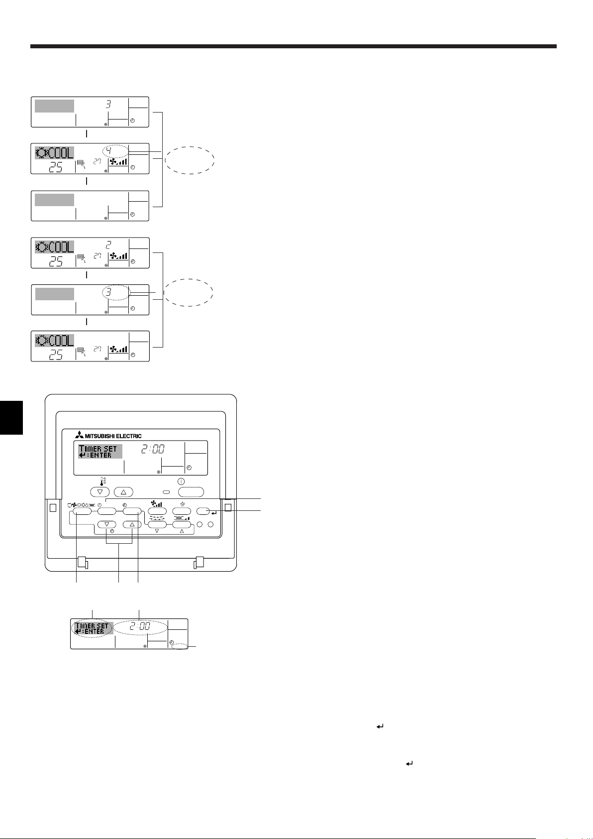
2.7.2. Using the Simple Timer
■ You can set the simple timer in any of three ways.
• Start time only: The air conditioner starts when the set time has
• Stop time only: The air conditioner stops when the set time has
• Start & stop times: The air conditioner starts and stops at the re-
■ The simple timer (start and stop) can be set only once within a 72-hour
period.
The time setting is made in hour increments.
elapsed.
elapsed.
spective elapsed times.
6
Note:
*1. Weekly Timer/Simple Timer/Auto Off Timer cannot be used at the same time.
*2. The simple timer will not operate when any of the following conditions is in
effect.
The timer is off; the system is in malfunction state; a test run is in progress;
the remote controller is undergoing self-check or remote controller check;
the user is in the process of selecting a function; the user is in the process
of setting the timer; the system is under central control. (Under these conditions, On/Off operation is prohibited.)
Page 7

ONHr
AFTER
SIMPLE
4
1
3
2
2. Operation
TIMER ON
OFFHrAFTER
SIMPLE
1
6
5
˚C
˚C
SIMPLE
7
˚C
˚C
ONHr
AFTER
SIMPLE
7
Timer Setting
Action (On or Off)
* “— —” is displayed if there
is no setting.
ss
sHow to Set the Simple Timer
ss
1. Be sure that you are at a standard control screen, and that the simple timer indicator is visible in the display (at 1).
When something other than the Simple Timer is displayed, set it to
SIMPLE TIMER using the function selection of remote controller (see
2.10. [4]–3 (3)).
2. Press the Timer Menu button B, so that the “Set Up” appears on the
screen (at 2). (Note that each press of the button toggles the display
between “Set Up” and “Monitor”.)
3. Press the ON/OFF button 1 to display the current ON or OFF simple
timer setting. Press the button once to display the time remaining to
ON, and then again to display the time remaining to OFF. (The ON/
OFF indication appears at 3).
•“ON” timer: The air conditioner will start operation when the
specified number of hours has elapsed.
•“OFF” timer: The air conditioner will stop operation when the
specified number of hours has elapsed.
4. With “ON” or “OFF” showing at 3: Press the appropriate Set Time
button A as necessary to set the hours to ON (if “ON” is displayed)
or the hours to OFF (if “OFF” is displayed) at 4.
• Available Range: 1 to 72 hours
5. To set both the ON and OFF times, repeat Steps 3 and 4.
* Note that ON and OFF times cannot be set to the same value.
6. To clear the current ON or OFF setting: Display the ON or OFF setting (see step 3) and then press the Check (Clear) button 0 so that
the time setting clears to “—” at 4. (If you want to use only an ON
setting or only an OFF setting, be sure that the setting you do not
wish to use is shown as “—”.)
7. After completing steps 3 to 6 above, press the Filter button 4 to
lock in the value.
Timer Setting
Note:
Your new settings will be cancelled if you press the Mode (Return) button
2 before pressing the Filter
8.
Press the Mode (Return) button 2 to return to the standard control screen.
button 4.
9. Press the Timer On/Off button 9 to start the timer countdown. When
the timer is running, the timer value is visible on the display. Be sure
that the timer value is visible and appropriate.
ss
sViewing the Current Simple Timer Settings
ss
1. Be sure that the simple timer indicator is visible on the screen (at 1).
2. Press the Timer Menu button B, so that the “Monitor” appears on the
screen (at 5).
• If the ON or OFF simple timer is running, the current timer value
will appear at 6.
• If ON and OFF values have both been set, the two values appear
alternately.
3. Press the Mode (Return) button 2 to close the monitor display and
return to the standard control screen.
ss
sTo Turn Off the Simple Timer...
ss
Press the Timer On/Off button 9 so that the timer setting no longer appears on the screen (at 7).
ss
sTo Turn On the Simple Timer...
ss
Press the Timer On/Off button 9 so that the timer setting becomes visible
at 7.
7
Page 8
AFTER OFF
AUTO OFF
3
1
2
ONHr
AFTER
SIMPLE
˚C
˚C
OFFHrAFTER
SIMPLE
SIMPLE
˚C
˚C
OFFHrAFTER
SIMPLE
ONHr
AFTER
SIMPLE
˚C
˚C
SIMPLE
AFTER OFF
AUTO OFF
PAR-21MAA
ON/OFF
FILTER
CHECK
OPERATION
CLEAR
TEST
TEMP.
MENU
BACK DAY
MONITOR/SET
CLOCK
ON/OFF
2A9
4
B
2. Operation
▲
▲
▲
▲
At Timer Start
At 3 hours after
timer start
At 7 hours after
timer start
At Timer Start
At 2 hours after
timer start
At 5 hours after
timer start
Display shows the timer’s ON setting (hours
remaining to ON).
Display changes to
show the timer’s OFF
setting (hours remaining to OFF). The time
displayed is OFF setting (7 hours) – ON setting (3 hours) = 4 hours.
The air conditioner
goes off, and will remain off until someone restarts it.
Display shows the timer’s OFF setting (hours
remaining to OFF).
Display changes to
show the timer’s ON
setting (hours remaining to ON). The time
displayed is ON setting
(5 hours) – OFF setting
(2 hours) = 3 hours.
The air conditioner
comes on, and will
continue to run until
someone turns it off.
Examples
If ON and OFF times have both been set at the simple timer, operation and
display are as indicated below.
Example 1:
Start the timer, with ON time set sooner than OFF time
ON Setting: 3 hours
OFF Setting: 7 hours
Example 2:
Start the timer, with OFF time is sooner than ON time
ON Setting: 5 hours
OFF Setting: 2 hours
Timer Setting
2.7.3. Using the Auto Off Timer
■ This timer begins countdown when the air conditioner starts, and shuts
the air conditioner off when the set time has elapsed.
■ Available settings run from 30 minutes to 4 hours, in 30-minute intervals.
Note:
*1. Weekly Timer/Simple Timer/Auto Off Timer cannot be used at the same time.
*2. The Auto Off timer will not operate when any of the following conditions is
in effect.
The timer is off; the system is in malfunction state; a test run is in progress;
the remote controller is undergoing self-check or remote controller check;
the user is in the process of selecting a function; the user is in the process
of setting the timer; the system is under central control. (Under these conditions, On/Off operation is prohibited.)
ss
sHow to Set the Auto Off Timer
ss
1. Be sure that you are at a standard control screen, and that the Auto
Off timer indicator is visible in the display (at 1).
When something other than the Auto Off Timer is displayed, set it to
AUTO OFF TIMER using the function selection of remote controller
(see 2.10. [4]–3 (3)).
2. Hold down the Timer Menu button B for 3 seconds, so that the “Set
Up” appears on the screen (at 2).
(Note that each press of the button toggles the display between “Set
Up” and “Monitor”.)
3. Press the appropriate Set Time button A as necessary to set the
OFF time (at 3).
4. Press the Filter button 4 to lock in the setting.
Note:
Your entry will be cancelled if you press the Mode (Return) button 2
before pressing the Filter
button 4.
8
Page 9

AFTER
TIMER
OFF
AUTO OFF
5
1
4
˚C
˚C
AUTO OFF
6
7
AUTO OFF
7
˚C
˚C
AFTER OFF
AUTO OFF
6
7
˚C
˚C
TIME SUN
FUNCTION
PAR-21MAA
ON/OFF
FILTER
CHECK
OPERATION
CLEAR
TEST
TEMP.
MENU
BACK DAY
MONITOR/SET
CLOCK
ON/OFF
4
1
1
2. Operation
˚C
˚C
FUNCTION
1
˚C
˚C
FUNCTION
1
˚C
˚C
1
5. Press the Mode (Return) button 2 to complete the setting procedure
and return to the standard control screen.
6. If the air conditioner is already running, the timer starts countdown
immediately. Be sure to check that the timer setting appears cor-
rectly on the display.
Timer Setting
Lock Indicator
ss
sChecking the Current Auto Off Timer Setting
ss
1. Be sure that the “Auto Off” is visible on the screen (at 1).
2. Hold down the Timer Menu button B for 3 seconds, so that “Moni-
tor” is indicated on the screen (at 4).
• The timer remaining to shutdown appears at 5.
3. To close the monitor and return to the standard control screen, press
the Mode (Return) button 2.
ss
sTo Turn Off the Auto Off Timer...
ss
● Hold down the Timer On/Off button 9 for 3 seconds, so that “Timer Off”
appears (at 6) and the timer value (at 7) disappears.
● Alternatively, turn off the air conditioner itself. The timer value (at 7) will
disappear from the screen.
ss
sTo Turn On the Auto Off Timer...
ss
● Hold down the Timer On/Off button 9 for 3 seconds. The “Timer Off “
indication disappears (at 6), and the timer setting comes on the display
(at 7).
● Alternatively, turn on the air conditioner. The timer value will appear at
7.
2.8. Locking the remote controller buttons (Operation
function limit controller )
■ If you wish, you can lock the remote controller buttons. You can use the
Function Selection of remote controller to select which type of lock to
use. (For information about selecting the lock type, see section 2.10. [4]-
2. (1)).
Specifically, you can use either of the following two lock types.
1 Lock All Buttons:
Locks all of the buttons on the remote controller.
2 Lock All Except ON/OFF:
Locks all buttons other than the ON/OFF button.
Note:
The “Locked” indicator appears on the screen to indicate that buttons are cur-
rently locked.
ss
sHow to Lock the Buttons
ss
1. While holding down the Filter button 4, press and hold down the
ON/OFF button 1 for 2 seconds. The “Locked” indication appears on
the screen (at 1), indicating that the lock is now engaged.
* If locking has been disabled in Function Selection of remote con-
troller, the screen will display the “Not Available” message when
you press the buttons as described above.
• If you press a locked button, the “Locked” indication (at 1) will blink
on the display.
ss
sHow to Unlock the Buttons
ss
1. While holding down the Filter button 4, press and hold down the
ON/OFF button 1 for 2 seconds—so that the “Locked” indication
disappears from the screen (at 1).
9
Page 10

ON/OFF
˚C
˚C
ERROR CODE
ON/OFF
CALL:XXXX
XXX:XXX
2. Operation
ON/OFF
ERROR CODE
ON/OFF
TEMP.
˚C
˚C
ON/OFF
TEMP.
˚C
˚C
ON/OFF
TEMP.
˚C
˚C
FILTER
2.9. Other indications
2.9.1. Centrally Controlled
● Displayed when operation is controlled by central controller, etc.
Restricted operations are shown below.
• ON/OFF (including timer operation)
• Operation mode
• Set temperature
Note:
May also be individually restricted.
2.9.2. Flashing Mode Indicator
■ When flashes continuously
Displayed when another indoor unit connected to the outdoor unit is
already operating in a different operation mode.
Match with the operation mode of the other indoor unit.
■ When mode switched after display flashes
Displayed when operation mode is restricted for each season by central
controller, etc.
Use another operation mode.
2.9.3. Flashing “Filter”
■ Indicates that the filter needs cleaning.
Clean the filter.
■ When resetting “FILTER” display
When the [FILTER] button is pressed two times successively after cleaning the filter, the display goes off and is reset.
If you have entered contact number to be called in the event of a problem, the screen displays this number. (You can set this up under Function Selection of remote controller. For information, refer to section 2.10.)
ON lamp
(Flashing)
Indoor Unit’s
Refrigerant
Address
Error Code
Indoor Unit No.
Alternating
Display
Error Code
When the Check button is pressed:
Note:
● When two or more different types of indoor unit are controlled, the cleaning
period differs with the type of filter. When the master unit cleaning period
arrives, “FILTER” is displayed. When the filter display goes off, the cumula-
tive time is reset.
● “FILTER” indicates the cleaning period when the air conditioner was used
under general indoor air conditions by criteria time. Since the degree of dirtiness depends on the environmental conditions, clean the filter accordingly.
● The filter cleaning period cumulative time differs with the model.
2.9.4. Flashing Error Codes
● If the ON lamp and error code are both flashing: This means that the air
conditioner is out of order and operation has been stopped (and cannot
resume). Take note of the indicated unit number and error code, then
switch off the power to the air conditioner and call your dealer or servicer.
● If only the error code is flashing (while the ON lamp remains lit): Operation is continuing, but there may be a problem with the system. In this
case, you should note down the error code and then call your dealer or
servicer for advice.
* If you have entered contact number to be called in the event of a
problem, push the Check button to display it on the screen. (You can
set this up under Function Selection of remote controller. For information, refer to section 2.10.)
10
Page 11

2. Operation
PAR-21MAA
ON/OFF
FILTER
CHECK
OPERATION
CLEAR
TEST
TEMP.
MENU
BACK DAY
MONITOR/SET
CLOCK
ON/OFF
F
G
C
D
B
I
A
H
E
2.10. Function selection of remote controller
The setting of the following remote controller functions can be changed using the remote controller function selection mode. Change the setting when
needed.
Item 1
1. Change Language
Language setting to display
Item 2
• Display in multiple languages is possible.
(“CHANGE LANGUAGE”)
2. Function limit
(“ FUNCTION SELEC-
TION”)
(1) Operation function limit setting (operation lock)
(“LOCKING FUNCTION”)
(2) Use of automatic mode setting (“SELECT AUTO
• Setting the range of operation limit (operation lock)
• Setting the use or non-use of “automatic” operation mode
MODE”)
(3) Temperature range limit setting (“LIMIT TEMP
• Setting the temperature adjustable range (maximum, minimum)
FUNCTION”)
3. Mode selection
(“MODE SELECTION”)
4. Display change
(“DISP MODE SETTING”)
(1) Remote controller main/sub setting (“CON-
TROLLER MAIN/SUB”)
(2) Use of clock setting (“CLOCK”)
(3) Timer function setting (“WEEKLY TIMER”)
(4) Contact number setting for error situation
(“CALL.”)
(1) Temperature display °C/°F setting (“TEMP
MODE °C/°F”)
(2) Suction air temperature display setting (“ROOM
TEMP DISP SELECT”)
(3) Automatic cooling/heating display setting
(“AUTO MODE DISP C/H”)
• Selecting main or sub remote controller
* When two remote controllers are connected to one group, one
controller must be set to sub.
• Setting the use or non-use of clock function
• Setting the timer type
• Contact number display in case of error
• Setting the telephone number
• Setting the temperature unit (°C or °F) to display
• Setting the use or non-use of the display of indoor (suction) air
temperature
• Setting the use or non-use of the display of “Cooling” or “Heat-
ing” display during operation with automatic mode
2.10.1. Function selection flowchart
[1] Stop the air conditioner to start remote controller function selection mode. → [2] Select from item 1. → [3] Select from item 2. → [4] Make the setting. (Details are specified
in item 3) → [5] Setting completed. → [6] Change the display to the normal one. (End)
Item 3 (Setting content)
Normal display (Display when
the air condition is not running)
(Hold down the E button and press the D button for two
seconds.)
* The display cannot be changed during the unit function
selection, the test run and the self diagnosis.
Item 1 Remote Controller Function Se-
Change Language
(“CHANGE LANGUAGE”)
Press the G button.
lection Mode
Item 2
Function limit
(“FUNCTION
SELECTION”)
Press the
E button.
Mode selection
(“MODE
SELECTION”)
Display change
(“DISP MODE
SETTING”)
Press the
E button.
Press the
G button.
Press the
E button.
Press the
G button.
Press the
E button.
Press the
G button.
→
Operation function limit setting (“LOCKING FUNCTION”)
→
→
Use of automatic mode setting (“SELECT AUTO MODE”)
Press the G button.
Temperature range limit setting (“LIMIT TEMP FUNCTION”)
→
Remote controller main/sub setting (“CONTROLLER MAIN/SUB”)
Press the G button.
Use of clock setting (“CLOCK”)
Timer function setting (“WEEKLY TIMER”)
Contact number setting for error situation (“CALL.”)
→
Temperature display °C/°F setting (“TEMP MODE °C/°F”)
→→→→→
Suction air temperature display setting (“ROOM TEMP DISP SELECT”)
Press the G button.
Automatic cooling/heating display setting (“AUTO MODE DISP C/H”)
(Hold down the E button and press
the D button for two seconds.)
* The remote controller records the
setting that is made in this way.
See [4]–1
Item 3
(Setting content)
Press the
D button.
See [4]–2. (1)
See [4]–2. (2)
See [4]–2. (3)
Press the
D button.
See [4]–3. (1)
See [4]–3. (2)
See [4]–3. (3)
See [4]–3. (4)
Press the
D button.
See [4]–4. (1)
See [4]–4. (2)
See [4]–4. (3)
NOTE
Timer operation stops when the display for
remote controller function selection is
changed to the normal one.
Dot display
The language that is selected in
CHANGE LANGUAGE mode appears on this display. English is
set in this manual.
11
Page 12

2. Operation
2.10.2. Detailed setting
[4]–1. CHANGE LANGUAGE setting
The language that appears on the dot display can be selected.
• Press the [ MENU] button G to change the language.
1 Japanese (JP), 2 English (GB), 3 German (D), 4 Spanish (E), 5 Russian (RU), 6 Italian (I), 7 Chinese (CH), 8 French (F)
[4]–2. Function limit
(1) Operation function limit setting (operation lock)
• To switch the setting, press the [ ON/OFF] button D.
1 no1 : Operation lock setting is made on all buttons other than the [ ON/OFF] button.
2 no2 : Operation lock setting is made on all buttons.
3 OFF (Initial setting value) : Operation lock setting is not made.
* To make the operation lock setting valid on the normal screen, it is necessary to press buttons (Press and hold down the [FILTER] and [ ON/
OFF] buttons at the same time for two seconds.) on the normal screen after the above setting is made.
(2) Use of automatic mode setting
When the remote controller is connected to the unit that has automatic operation mode, the following settings can be made.
• To switch the setting, press the [ ON/OFF] button D.
1 ON (Initial setting value) : The automatic mode is displayed when the operation mode is selected.
2 OFF : The automatic mode is not displayed when the operation mode is selected.
(3) Temperature range limit setting
After this setting is made, the temperature can be changed within the set range.
• To switch the setting, press the [ ON/OFF] button D.
1 LIMIT TEMP COOL MODE :
The temperature range can be changed on cooling/dry mode.
2 LIMIT TEMP HEAT MODE :
The temperature range can be changed on heating mode.
3 LIMIT TEMP AUTO MODE :
The temperature range can be changed on automatic mode.
4 OFF (initial setting) : The temperature range limit is not active.
* When the setting, other than OFF, is made, the temperature range limit setting on cooling, heating and automatic mode is made at the same time.
However, the range cannot be limited when the set temperature range has not changed.
• To increase or decrease the temperature, press the [ TEMP. ( ) or ( )] button F.
• To switch the upper limit setting and the lower limit setting, press the [ ] button H. The selected setting will flash and the temperature can be
set.
• Settable range
Cooling/Dry mode: Lower limit: 19°C ~ 30°C Upper limit: 30°C ~ 19°C
Heating mode: Lower limit: 17°C ~ 28°C Upper limit: 28°C ~ 17°C
Automatic mode: Lower limit: 19°C ~ 28°C Upper limit: 28°C ~ 19°C
* The settable range varies depending on the unit to connect (Mr. Slim units, CITY MULTI units, and intermediate temperature units)
[4]–3. Mode selection setting
(1) Remote controller main/sub setting
• To switch the setting, press the [ ON/OFF] button D.
1 Main : The controller will be the main controller.
2 Sub : The controller will be the sub controller.
(2) Use of clock setting
• To switch the setting, press the [ ON/OFF] button D.
1 ON : The clock function can be used.
2 OFF : The clock function cannot be used.
(3) Timer function setting
• To switch the setting, press the [ ON/OFF] button D (Choose one of the followings.).
1 WEEKLY TIMER (initial setting on MA deluxe) : The weekly timer can be used.
2 AUTO OFF TIMER : The auto off timer can be used.
3 SIMPLE TIMER (Default setting on MA smooth) : The simple timer can be used.
4 TIMER MODE OFF : The timer mode cannot be used.
* When the use of clock setting is OFF, the “WEEKLY TIMER” cannot be used.
(4) Contact number setting for error situation
• To switch the setting, press the [ ON/OFF] button D.
1 CALL OFF : The set contact numbers are not displayed in case of error.
2 CALL **** *** ****: The set contact numbers are displayed in case of error.
CALL_ : The contact number can be set when the display is as shown on the left.
• Setting the contact numbers
To set the contact numbers, follow the following procedures.
Move the flashing cursor to set numbers. Press the [ TEMP. ( ) and ( )] button F to move the cursor to the right (left). Press the [ CLOCK
( ) and ( )] button C to set the numbers.
12
Page 13

2. Operation
A
B
[4]–4. Display change setting
(1) Temperature display °C/°F setting
• To switch the setting, press the [ ON/OFF] button D.
1 °C : The temperature unit °C is used.
2 °F : The temperature unit °F is used.
(2) Suction air temperature display setting
• To switch the setting, press the [ ON/OFF] button D.
1 ON : The suction air temperature is displayed.
2 OFF : The suction air temperature is not displayed.
(3) Automatic cooling/heating display setting
• To switch the setting, press the [ ON/OFF] button D.
1 ON : One of “Automatic cooling” and “Automatic heating” is displayed under the automatic mode is running.
2 OFF : Only “Automatic” is displayed under the automatic mode.
3. Care and cleaning
3.1. Cleaning the filters and the indoor unit
Cleaning the filters
• Clean the filters using a vacuum cleaner. If you do not have a vacuum
cleaner, tap the filters against a solid object to knock off dirt and dust.
• If the filters are especially dirty, wash them in lukewarm water. Take care
to rinse off any detergent thoroughly and allow the filters to dry completely before putting them back into the unit.
Caution:
• Do not dry the filters in direct sunlight or by using a heat source,
such as an electric heater: this may warp them.
• Do not wash the filters in hot water (above 50°C), as this may warp
them.
• Make sure that the air filters are always installed. Operating the
unit without air filters can cause malfunction.
Caution:
• Before you start cleaning, stop operation and turn OFF the power
supply.
• The air filter should be obtained locally. Be sure to check on the
location and the way of setting with the contractor when the unit
perform a trial run. (Example) The air filter should be attached to
the indoor unit’s air intake (rear side of unit).
AAir intake
BFilter
4. Troubleshooting
Before you call out a repair man, check the following table to see whether there is a simple solution to your problem.
[for wired remote controller]
Problem
Unit does not cool or heat very well.
The unit stops operating before ar-
riving at the set temperature in the
heating mode.
A white mist is expelled from the indoor unit.
The indicators of the remote controller do not light up when operated.
CENTRALLY CONTROLLED is displayed in the remote controller.
Clean the filter.
Frost forms when the outdoor tem-
perature is low and humidity is high.
Wait for about 10 minutes for the frost
to melt.
This may occur just after the unit is
turned on when a high level of humidity is present in the room.
Turn on the power switch. “ ” will
be displayed.
The start and stop functions of the
remote controller are not available
when the CENTRALLY CONTROLLED message is lit.
Solution
The start and stop functions are not
available just after restarting the unit.
“PLEASE WAIT” is displayed in the
remote controller.
An error code is displayed in the remote controller.
If none of the above apply, turn the main switch off and contact the dealer from whom you bought the air-conditioner, telling him the model name and the
nature of the problem. Do not try to fix the unit yourself.
Problem
Solution
Wait about three minutes (operation
has stopped to prevent damage to
the air conditioner).
An automatic startup test is being
performed (will last for about two minutes).
A self-diagnostic function is being
performed to preserve the air conditioner.
*Do not attempt to make repairs
yourself. Turn the main switch off
and contact the dealer from whom
you bought the air conditioner. Provide him or her with the name of the
unit and the information displayed
in the remote controller.
13
Page 14

4. Troubleshooting
In any of the following cases, turn off the main power switch and contact your local dealer for service:
• The operation lamp (in the remote controller) flashes.
• The switches do not work properly.
• The circuit breaker trips frequently (or the fuse blows frequently).
• Water has accidentally been splashed into the unit.
• Water leaks from the unit.
• Something is accidentally dropped into the air-conditioner.
• An unusual noise is heard during operation.
The following do not indicate any malfunction:
Odours: smells such as tobacco or cosmetic odours may persist after they have been sucked into the unit.
Sound of liquid flowing inside indoor unit: this can occur during or after operation and is simply the sound of refrigerant being circulated inside the unit.
Ticking sound coming from indoor unit: this can occur when cooling or heating has just begun or has just stopped. It is caused by the indoor unit shrinking
or expanding slightly due to the change in temperature.
NOTE: The refrigerant charged in the air conditioner is safe. Refrigerant normally does not leak, however, if refrigerant gas leaks indoors, and comes into contact
with the fire of a fan heater, space heater, stove, etc., harmful substances will be generated.
Be sure to ask the service representative whether there is refrigerant leakage or not when repairs are carried out.
5. Installation, relocation and inspection
Installation place
Avoid installing the air conditioner in the following places.
• Where flammable gas could leak.
Inverter type
Radio
fluorescent lamp
To prevent picture
distortion or
noise, keep 1 m
or more apart.
TV
100 mm or more
Wellventilated dry
place
400 mm or more
Wall, etc.
Caution:
Do not install the unit where flammable gas could leak.
If gas leaks and collects around the unit, it may cause an explosion.
• Where there is much machine oil.
• Salty place such as the seaside.
• Where sulfide gas is generated such as a hot spring.
• Where there is oil splashing or much oily smoke.
Electrical work
• Provide an exclusive circuit for power supply of the air conditioner.
• Be sure to observe the breaker capacity.
To prevent the effect
of a fluorescent lamp,
keep it away as far
apart as possible.
Warning:
• The customer should not install this unit. If the unit is installed incorrectly, fire, electric shock, injury due to a falling unit, water leakage, etc.
may result.
• Do not connect using branched outlet or an extension cord, and do not attach many loads to one electric outlet.
A fire or electric shock may result from poor contact, poor insulation, exceeding the permissible current, etc.
Consult your dealer.
Caution:
• Apply grounding
Do not connect a grounding wire to a gas pipe, water pipe, lightning rod or ground wire of a telephone.
If a grounding is incorrect, it may cause an electric shock.
• Install an earth leakage breaker depending on the place where the air conditioner is to be installed (humid place, etc.).
If the earth leakage breaker is not installed, it may cause an electric shock.
Inspection and maintenance
• When the air conditioner is used for several seasons, the capacity may be lowered due to dirt inside the unit.
• Depending upon the conditions of use, an odor may be generated or dirt, dust, etc. may prevent proper drainage.
• It is recommended to apply inspection and maintenance (charged) by a specialist in addition to normal maintenance. Consult your dealer.
Also consider operation sound
• Do not put an object around the air outlet of the outdoor unit. It may cause lowering of capacity or increase operating sound.
• If abnormal sound is heard during operation, consult your dealer.
Relocation
• When the air conditioner is to be removed or reinstalled because of rebuilding, moving, etc., special techniques and work are required.
Warning:
Repair or relocation should not be done by the customer.
If this is done incorrectly, it may cause a fire, electric shock, injury by dropping of the unit, water leakage, etc. Consult your dealer.
Disposal
• To dispose of this product, consult your dealer.
14
If you have any question, consult your dealer.
Page 15

6. Specifications
Function
Power supply
Capacity
Input kW
Indoor unit
Fan
Weight kg
Outdoor unit
Noise level (Lo-Hi) dB (A)
Refrigerant R410A kg
Weight kg
Notes: 1. Rating conditions (cooling) Indoor : 27°C DB, 19°C WB Outdoor : 35°C DB
2. Rating conditions (heating) Indoor : 20°C DB Outdoor : 7°C DB, 6°C WB
3. Specifications subject to change without notice.
Guaranteed operating range
Cooling
Heating
Units should be installed by licensed electric contractor accordingly to local code requirement.
Model
kW
BTU/h
Airflow (Lo-Hi) CMM
Ext. static
pressure
Noise level (Lo-Hi) dB (A)
Upper limit 32°C DB, 23°C WB 46°C DB, – 43°C DB, –
Lower limit 21°C DB, 15°C WB -10°C DB, –
Upper limit 27°C DB, – 24°C DB, 18°C WB
Lower limit 20°C DB, – -10°C DB, -11°C WB
Pa (mmAq)
Indoor
SEZ-KA35VA
Cooling Heating
3.5 4.0
11,900 13,600
1.06 1.10
SEZ-KA35VA
10-13
Std. : 30 (3)
Max. : 50 (5)
30-35
33.5
SUZ-KA35VA
48
1.05
35
Outdoor
KA35 KA50, KA60
Cooling Heating
~/N, 230V, 50Hz
5.0 5.9
17,100 20,100
1.78 1.84
SEZ-KA50VA
SEZ-KA50VA
12-17
Std. : 30 (3)
Max. : 50 (5)
31-39
33.5
SUZ-KA50VA
55
1.6
53
SEZ-KA60VA
Cooling Heating
5.5 6.9
18,800 23,500
1.96 2.45
SEZ-KA60VA
12-20
Std. : 30 (3)
Max. : 50 (5)
32-43
33.5
SUZ-KA60VA
55
1.8
53
15
Page 16

This product is designed and intended for use in the residential,
commercial and light-industrial environment.
The product at hand is
based on the following
EU regulations:
• Low Voltage Directive 73/23/ EEC
• Electromagnetic Compatibility Directive 89/
336/ EEC
Please be sure to put the contact address/telephone number on
this manual before handing it to the customer.
BG79U394H01
HEAD OFFICE: MITSUBISHI DENKI BLDG., 2-2-3, MARUNOUCHI, CHIYODA-KU, TOKYO 100-8310, JAPAN
Printed in Thailand
 Loading...