

Page 1

FOREWORD
This service manual describes the specifications as well as the maintenance and
adjustment procedures for Mitsubishi diesel engines. This manual also includes the
detailed information on basic and special tools as the need arises.
The Mitsubishi diesel engines can offer highly efficient and reliable performance for
many years to come, which, however, only can be achieved through the proper
handling and the periodical inspection/maintenance work exercised in according to
the procedures of disassembly, inspection/adjustment and reassembly described in this
manual.
Before attempting any work on your engine, thoroughly read this manual to
familiarize with the engine and the required procedures of the work.
All information contained in this manual is based on the engine produced at the time
of publication and is subject to change as the engine improved without notice.
Pub. No. 99619-12140
Page 2

HOW TO USE THIS MANUAL
This Service Manual describes the specifications of Mitsubishi diesel engines (land and standard applications)
and relevant service standards, as well as the procedures for servicing the engines such as for disassembly,
inspection, repair and reassembly. This manual is divided into Groups. Each Group covers a specific area of
the engine.
The fuel injection pump, the governor and the turbocharger are handled in a separate manual.
Major contents of Groups are listed on the “General Contents” page. Detailed contents of each Group are
listed on the first page of that Group.
For information on the operations and recommended inspection/maintenance schedule of forklift trucks,
please refer to the operator’s manual for the forklift truck. For information on components/parts and spares
ordering procedures, refer to the parts catalogue. For information on structures and functions, refer to
appropriate training materials.
1. Notes on descriptions
(1) Parts shown in Figures as well as in the text are numbered in the order of disassembly.
(2) Inspecting points during disassembly are shown in the Disassembly figures by enclosing in the box.
(3) Service standards for inspection and repair are listed on the appropriate pages of this manual where the
relevant descriptions are made. Also, a comprehensive listing of service standards is provided in Group
1.
(4) Parts reassembly sequence is provided below the Figure of that reassembly in the form of ⑤→④→③
→②→①.
(5) In this manual, the following marks are provided to draw the reader’s attention to the safety notes
described under the marks.
・・・・ This indicates a dangerous situation which can highly likely result in death or
serious injury unless avoided.
・・・・ This indicates a potentially dangerous situation which may possibly lead to
death or serious injury unless avoided.
・・・・ This indicates a potentially dangerous situation which may cause minor to
moderate injury unless avoided.
・・・・This indicates a potential danger in which property damage may result unless
avoided.
(6) Wherever hardware tightening requires the application of engine oil, “WET” is mentioned. If not
Note: ・・・・ This stresses important points or provides useful tips on engine operations and
service.
mentioned, tighten the hardware “dry” (engine oil should not be applied).
Page 3

2. Terms
Nominal value ······This is the nominal dimension of the part being measured.
Standard value ······ This is the dimension of the individual part being measured, the clearance between the
parts in question, or the standard performance in question. Standard values have been
arranged within the range appropriate for the inspection being carried out, and are not
necessarily the design values.
Limit·····················Parts that have reached the limit value should be replaced or repaired whichever is
appropriate.
3. Abbreviations and standards
・BTDC = Before Top Dead Center
・ATDC = After Top Dead Center
・BBDC = Before Bottom Dead Center
・ABDC = After Bottom Dead Center
・TIR = Total Indicator Reading
・API = American Petroleum Institute
・ASTM = American Society for Testing and Materials
・JIS = Japan Industrial Standards
・LLC = Long Life Coolant
・MIL = Military Specifications
・MSDS = Material Safety Data Sheets
・SAE = Society of Automotive Engineers
4. Units
Values shown in this manual are based on SI units (International System of Units). The corresponding metric
values are shown in ( ) immediately after the SI values. The SI to metric conversions are based on the
following.
・Pressure: 1 MPa = 10.197 kgf/cm
・Torque: 1 N・m = 0.10197 kgf・m
・Force: 1 N = 0.10197 kgf
・Horsepower: 1 kW = 1.341 HP = 1.3596 PS
・Meter of mercury: 1 kPa = 0.7 cmHg
・Meter of water: 1 kPa = 10.197 cmH
・Rotational speed: 1 min
-1
= 1 rpm
2
O (cmAq)
2
Page 4
GENERAL CONTENTS
Group No. Group Name Page
0 SAFETY CAUTIONS 0 - 1
GENERAL 1 - 1
SERVICE STANDARDS 1 -11
1
2 Engine Main Parts
3 Fuel System
4 Lubrication System
5 Cooling System
6
7 Air starter System
TOOLS LIST 1 -21
OVERHAUL TIMING 1 -25
REMOVAL PREPARATIONS 1 -29
Inlet and Exhaust
Systems
ENGINE MAIN PARTS - DISASSEMBLY 2 - 1
ENGINE MAIN PARTS - INSPECTION AND
CORRECTION
ENGINE MAIN PARTS - REASSEMBLY 2 -33
FUEL SYSTEM - REMOVAL 3 - 1
FUEL SYSTEM - DISASSEMBLY,
INSPECTION AND REASSEMBL Y
FUEL SYSTEM - INSTALLATION 3 -25
OIL SYSTEM - REMOVAL 4 - 1
OIL SYSTEM - DISASSEMBLY,
INSPECTION AND REASSEMBL Y
OIL SYSTEM - INSTALLATION 4 - 9
COOLING SYSTEM - REMOVAL 5 - 1
COOLING SYSTEM - DISASSEMBLY,
INSPECTION AND REASSEMBL Y
COOLING SYSTEM - INSTALLATION 5 - 9
INLET AND EXHAUST SYSTEMS -
REMOVAL
INLET AND EXHAUST SYSTEMS DISASSEMBLY, INSPECTION AND
REASSEMBLY
INLET AND EXHAUST SYSTEMS INSTALLATION
ELECTRICAL SYSTEM - REMOVAL 7 - 1
ELECTRICAL SYSTEM - DISASSEMBLY,
INSPECTION AND REASSEMBL Y
ELECTRICAL SYSTEM - INSTALLATION 7 -25
2 -17
3 - 9
4 - 5
5 - 5
6 - 1
6 - 5
6 - 7
7 - 7
Engine -
8
9 Others
Supplement
Engine Inspection Sheets
Inspection/Adjustment,
Running-in Trial and
Performance Test
ENGINE - INSPECTION / ADJUSTMENT 8 - 1
RUNNING-IN TRIAL 8 -12
PERFORMANCE TEST 8 -13
DISASSEMBL Y AND REASSEMBLY OF
GENERAL PARTS
9 - 1
Page 5

Page 6

SAFETY CAUTIONS
Warning Risk of fire and explosion ···0-2
●Never use open fire ······························0-2
●Keep things tidy around the engine ··········0-2
●Do not open the crankcase until it has
cooled down
●Pay attention to fuel and oil leakage
●Use explosion-proof light
●Prevent short circuit
●Keep fire extinguisher and first-aid kit
at hand
········································0-2
·········0-2
························0-2
······························0-2
··············································0-2
Warning Risk of entanglement into
the machine························0-3
●Keep guards on the rotating parts ············0-3
●Ensure safety in the surrounding area
when starting the engine
●Keep away from rotating parts while the
engine is running
●Lockout/tagout
●Always stop the engine before any
inspection/service
●Remove the turning gear after use
··································0-3
·····································0-3
·································0-3
························0-3
···········0-3
Warning Risk of burn ························0-4
●Do not touch the engine while it is
running or for a while after it is stopped
●Be careful when opening/closing the
radiator cap
●Replenish coolant only when
the coolant in the system is cold
●Do not remove heat insulating material ·····0-4
·········································0-4
··············0-4
·····0-4
Warning Exhaust gas is
poisonous···························0-4
●Ensure good ventilation while the
engine is running
··································0-4
Warning Hearing difficulty·················0-4
●Wear ear protector································0-4
Warning Beware of falling engine·····0-5
●Exercise caution when lifting the engine····0-5
●Do not climb on the engine
●Secure your foothold when carrying out
service
···············································0-5
·····················0-5
Caution Use correct engine oil
and LLC······························0-5
●Only use the specified fuel, engine oil
and coolant (LLC)
·································0-5
●Handle LLC with care
●Lawful disposal of waste oil and
coolant
···············································0-5
····························0-5
Caution Handling of battery··············0-6
●Handle the battery with care····················0-6
Caution How to handle
emergencies·······················0-6
●Engine overheat - Idle to cool down,
then stop the engine
●Never restart the engine after a su dden
stop unless the cause is eliminated
●Stop the engine immedia t ely upon oil
pressure drop
●Stop the engine immedia t ely upon broken
fan belt
···············································0-6
······································0-6
·····························0-6
··········0-6
Caution Other considerations···········0-7
●Never alter or modify the engine ··············0-7
●Do not tamper with sealing
●Daily and periodical inspection
●Running-in period
●Warming up the engine
●Do not overload the engine·····················0-7
●Cooling down the engine
●Do not spill water onto the engine ···········0-7
●Air cleaner maintenance precautions
●Observe safety rules at work sites
●Wear appropriate clothes and protective
gear
···················································0-8
●Use appropriate tools when carrying out service
·································0-7
·····················0-7
················0-7
··························0-7
························0-7
········0-8
············0-8
0-8
●Do not operate the starter continuously
●The battery switch must be kept ON while
the engine is running
●Precautions for road transport
·····························0-8
·················0-8
·····0-8
Page 7
SAFETY CAUTIONS
W arning Risk of fire and explosion
●Never use open fire
When topping up or replacing fuel
or engine oil, or cleaning parts in
wash oil, do not light a match,
smoke or use any other open fire
nearby. Doing these is extremely
dangerous as fuel and oils can catch fire.
Completely wipe off any spilt fuel or engine oil as
they are flammable and can be a fire hazard.
Store fuel and engine oil in a well-ventilated place.
Firmly tighten the cap of the container.
●Keep things tidy around the engine
Keep fuel, engine oil or any other flammables as
well as explosives and other dangerous materials
away from the engine. These materials can ignite
and explode.
Keep the engine and the surrounding area free of
waste, dirt, foreign matter, etc. These substances
can be a fire hazard and invite overheating. In
particular, ensure that the top of the battery is clean
after service operations. Any waste left on the
battery can cause short circuit.
Keep a running engine at least 1 m (3.3 ft.) away
from the surrounding building or equipment to
eliminate the risk of fire.
●Do not open the crankcase until it has
cooled down
Do not attempt to open the crankcase side cover
immediately after the engine is stopped. Wait at
least 10 minutes until the engine has sufficiently
cooled down.
If fresh air flows into the crankcase with the engine
still hot, the remaining mist of oil may ignite and
cause explosion.
●Pay attention to fuel and oil leakage
If leakage of fuel or oil is found, immediately take
measures to stop it.
If leaking fuel or engine oil spills over the heated
engine, fire may start, possibly leading to bodily
injury or equipment damage.
●Use explosion-proof light
When checking fuel, engine oil, coolant, battery
electrolyte, etc., use explosion-proof light. If
ordinary light is used, these fluids may ignite and
explode.
●Prevent short circuit
Before inspecting or servicing the
electrical/electronic system, disconnect the negative
(-) cable from the battery terminal. Failure to
observe this can cause the circuit to short, possibly
starting a fire.
Loose terminals and damaged cables/wires can
cause short circuit or even fire. Before carrying out
service operation, check for loose or damaged
components and repair or replace as required.
●Keep fire extinguisher and first-aid kit
at hand
Keep a fire extinguisher at hand.
Become familiar with the handling
of the fire extinguisher.
Store a first-aid kit at the designated
place. The kit should be kept fully
supplied so that it can serve the purpose at any time.
Establish a set of actions to take in the event of fire
or accident, including emergency contact numbers
and means of communication.
0 - 2
Page 8
W arning Risk of entanglement into the machine
SAFETY CAUTIONS
●Keep guards on the rotating parts
Ensure that all guards are correctly
installed over the rotating parts of
the engine. Damaged or loose
guards should be repaired.
Never attempt to remove the
camshaft cover, rocker cover or any other guards
form rotating parts while the engine is running.
Never leave exposed the drive belts and related
couplers for auxiliaries and radiator. They should
also be covered with guards.
Never remove these guards.
●Ensure safety in the surrounding area
when starting the engine
Before starting the engine, ensure that no one is near
the electric power generator and that no tools or
foreign matter are left behind. Shout to people
around you so that they will know you are starting
the engine.
Never start the engine if a “Do not start” tag or any
other similar message is posted on the starter switch,
etc.
●Keep away from rotating parts while
the engine is running
Never stand near the rotating parts
while the engine is running.
Do not place objects near the rotating
parts that are likely to be caught by
these parts.
Should any part of human body (or tool) is caught by
the rotating parts, dismemberment or other bodily
injury will result.
●Lockout/tagout
Perform lockout/tagout before carrying out any
inspection/service.
Lockout/tagout is an ideal way of disconnecting the
machine/equipment from the power source.
To lockout/tagout, remove the starter switch key,
place the battery switch in the “OFF” position, and
post a “Do not start” tag or other similar message on
the starter switch.
The starter switch key should then be carried by the
person who is going to perform inspection/service.
If an air start system is used, close the air tank source
valve and post a “Do not open” tag or other similar
message.
●Always stop the engine before any
inspection/service
Always stop the engine before performing any
inspection/service. Never attempt to adjust belt
tension while the engine is running. Otherwise, the
operator runs a great risk of becoming entangled into
the rotating parts and seriously injured.
●Remove the turning gear after use
Be sure to remove the turning gear after use. Never
start the engine with the turning gear still installed or
“engaged.” Otherwise, the engine will break and
possibly someone may become injured.
0 - 3
Page 9

SAFETY CAUTIONS
W arning Risk of burn
●Do not touch the engine while it is
running or for a while after it is
stopped
Never touch any part of the engine
while it is running or for a while after
it is stopped. Otherwise, you may
become burned.
Use a coolant temperature gauge to confirm that the
engine has sufficiently cooled down before
performing any inspection/service.
●Be careful when opening/closing the
radiator cap
Never attempt to open the radiator cap while the
engine is running and for a while after it is stopped.
Stop the engine and wait until the coolant
temperature has sufficiently dropped before opening
the cap.
Slowly open the radiator cap to allow the internal
pressure to escape. To prevent possible burn, wear
thick rubber gloves or cover the cap with cloth to
protect your hands from escaping vapor.
Tighten the radiator cap firmly.
Coolant is extremely hot while the engine is running
or for a while after the engine is stopped. You may
become burned by extremely hot vapor or coolant
that will gush out if the radiator cap is opened.
● Replenish coolant only when the
coolant in the system is cold
Do not replenish coolant for a while after the engine
is stopped. Replenish coolant when the coolant in
the system is sufficiently cold. Otherwise, you may
become burned.
● Do not remove heat insulating
material
The exhaust system components become extremely
hot and therefore are covered with heat insulating
material. Never remove the material. If the material
needs to be removed at all for inspection/service, be
sure to install it again after the operation.
W arning Exhaust gas is
poisonous
● Ensure good ventilation while the
engine is running
If the engine is installed inside a
building and the exhaust gas is
directed outside through a duct,
regularly check the duct for any
leakage through the joints etc.
Do not run the engine in a building (warehouse,
tunnel, etc.), confined space, or other poorly
ventilated places if the engine is used for a portable
generator. If the engine needs to be run in a buildin g
at all, ensure to direct the exhaust gas outside and
provide sufficient ventilation. Also, take care not to
direct the exhaust gas towards nearby plants or
animals, if any.
Engine exhaust gas contains carbon monoxide and
other substances that are harmful to humans.
Running the engine in a poorly ventilated place can
cause exhaust gas poisoning.
Warning Hearing
difficulty
●Wear ear protector
W ear ear protector whenever entering
the engine room. Otherwise, the
combustion and mechanical noises
may cause you to develop hearing
difficulty.
0 - 4
Page 10

SAFETY CAUTIONS
Warning Beware of
falling engine
● Exercise caution when lifting the
engine
The wire rope used to lift the engine
should have enough strength to
withstand the weight of the engine.
Attach the specified lifting gear onto the
lifting hangers on the engine.
Ensure that the engine is well balanced when it is
lifted by taking into account the engine’s center of
gravity.
The angle of wire rope relative to the lifting hangers
should be maintained at 60º or less. Above this, the
hangers may be subjected to overload and break.
If direct contact between the wire rope and the
engine is anticipated, protect them from damage by
covering them with cloth or other soft material.
● Do not climb on the engine
Do not climb onto the engine, nor place a foot on the
components on the side of the engine.
Otherwise, you may not only break the engine
components but also fall and become injured.
Use a stool or a platform to work on the top of the
engine. Be careful not to slip and fall.
● Secure your foothold when carrying
out service
Use a stable stool or platform when
working on the top of the engine or
other areas of the engine difficult to
reach.
Do not use a rickety stool nor
substitute a box of parts. Otherwise, you may fall
and become injured.
Do not leave anything on the stool.
Caution Use correct
engine oil and LLC
● Only use the specified fuel, engine oil
and coolant (LLC)
Only use the fuel, engine oil and coolant (LLC) that
are specified in this manual. Handle them with
sufficient care.
Using fluids other than those specified in this
manual or incorrect use of those specified in this
manual will lead to many problems and may
possibly cause failures.
Use the specified engine oil and LLC according to
the instructions of MSDS (Material Safety Data
Sheets) issued by and available from the
manufacturers.
● Handle LLC with care
LLC is a strong alkali. Be careful not to drink it by
mistake or allow it to contact your eyes.
Old coolant (containing LLC) that has been drained
off is toxic. Do not dispose of it carelessly. Dispose
of it in accordance with the applicable laws and
regulations.
● Lawful disposal of waste oil and
coolant
Do not dispose of waste oil or coolant carelessly.
Doing so is harmful to the environment and is
prohibited by law.
Harmful substances such as waste oil and coolant
should be disposed of in a manner that complies with
the applicable laws and regulations.
0 - 5
Page 11
SAFETY CAUTIONS
Caution Handling of
battery
● Handle the battery with care
・ Batteries emit hydrogen and
oxygen gases, both of which are
flammable. Never use open fire or
generate sparks near the battery.
Otherwise, these gases may ignite and explode.
・ Do not use the battery if the electrolyte level has
dropped below the minimum line. Otherwise, the
battery may explode.
・ Be careful not to inadvertently place a metal
object such as tool between the battery terminals.
・ Always disconnect the negative (-) terminal first,
then the positive (+) terminal, from the battery.
Always connect the positive (+) terminal first,
then the negative (-) terminal, to the battery.
・ Recharge the battery in a well ventilated place,
with all battery plugs removed.
・ The battery terminals should have a positive
connection. Loose terminals can generate sparks,
possibly causing the battery to explode.
・ Before servicing or performing electric welding
on the electrical/electronic system, position the
battery switch in the OPEN/OFF position or
disconnect the negative (-) terminal of the battery
to isolate the electrical/electronic circuit.
・ The battery electrolyte contains dilute sulfuric
acid. Incorrect handling may lead to loss of
eyesight or burn. Never drink battery electrolyte.
・ Wear protective goggles and rubber gloves when
maintaining the battery (replenishing, recharging,
etc.).
・ If your skin or clothing has come into contact with
battery electrolyte, immediately wash the affected
area with plenty of water and then thoroughly
clean with soap.
・ Should your eyes come into contact with battery
electrolyte, loss of eyesight may result.
Immediately wash your eyes with plenty of fresh
water and seek medical attention immediately.
・Should you inadvertently drink battery electrolyte,
repeatedly gargle with plenty of water and then
drink plenty of water. Seek medical attention
immediately.
Caution How to handle
emergencies
● Engine overheat - Idle to cool down,
then stop the engine
In the event of engine overheat, do not stop the
engine immediately. Doing so may cause the
coolant temperature to rise quickly and the engine
may seize. Instead, run the engine at low idle for a
while to cool it down. Then, stop the engine. Do not
attempt to replenish coolant for a while after the
engine is stopped. Otherwise, the cylinder head etc.,
which may still be hot, is cooled down rapidly and
may break. Wait until the engine is sufficiently cold
and then top up slowly.
● Never restart the engine after a
sudden stop unless the cause is
eliminated
If the engine has suddenly stopped with some alert
signals, do not restart immediately. Otherwise, the
engine may seriously become damaged. Locate and
eliminate the cause before restarting.
● Stop the engine immediately upon oil
pressure drop
If the oil pressure has dropped, immediately stop the
engine. Otherwise, bearings etc. may seize. Inspect
the oil system and components.
● Stop the engine immediately upon
broken fan belt
If the fan belt has broken, immediately stop the
engine. Otherwise, the engine will overheat. Also,
coolant vapor will gush out from the reserve tank
and radiator and you may get burned.
0 - 6
Page 12

Caution Other considerations
SAFETY CAUTIONS
● Never alter or modify the engine
Altering or modifying the engine in any way will
nullify the warranty.
A modified engine may not only break but also lead
to injury.
● Do not tamper with sealing
To help ensure trouble-free operation of the engine,
the fuel control link has been sealed to achieve the
correct fuel injection volume and engine speed. If
the sealed setting is tampered with, the following
will result and the correct functioning of the engine
is no longer guaranteed.
・ Sliding and rotating parts will wear faster.
・ Various parts will seize/become damaged.
・ The engine will consume more fuel and oil.
・ The governor and fuel injection volume go out of
balance, reducing the engine performance.
● Daily and periodical inspection
Perform the daily and periodical inspection in
accordance with the Operation and Maintenance
Manual.
Failure to observe the instructions of the manual
may lead to many problems, and the various engine
parts may eventually fail, possibly causing a serious
accident.
● Running-in period
A brand new engine requires a running-in period of
50 hours, during which never put the engine under
severe load. Otherwise, the service life of the engine
will be reduced.
● Warming up the engine
Before starting work, warm up the engine by
running it at low idle for 5 to 10 minutes.
Warming up the engine will not only smoothen the
operation of various engine parts but also help
extend its service life. It also helps maximize the
performance and achieve economical running of the
engine.
Do not warm up the engine longer than necessary.
Doing so facilitates carbon deposit on the cylinders,
possibly leading to poor combustion.
● Do not overload the engine
Do not continue to run the engine if it emits black
smoke.
Overloaded running of the engine (accompanied by
black smoke) not only consumes excessive fuel but
also facilitates carbon deposit and thus shortens the
service life of the engine.
● Cooling down the engine
Before stopping the engine, cool it down (by running
it at low idle) for 5 to 6 minutes.
Stopping the engine suddenly while it is heavily
loaded will result in some areas of the engine
remaining extremely hot for a while, which is
detrimental to the long service life of an engine.
While the engine is being run at low idle for cooling,
check the engine for any problems.
● Do not spill water onto the engine
Ensure that no rainwater etc. enters into the engine
from the exhaust or inlet manifold, or via any other
routes.
Do not run the engine while at the same time
washing it. Otherwise, cleaning fluid (water) may
be sucked into the engine.
If the engine is started with water trapped in the
combustion chambers, water hammering will result,
causing the engine to fail and possibly leading to a
serious accident.
0 - 7
Page 13

SAFETY CAUTIONS
● Air cleaner maintenance precautions
Wear of engine parts is accelerated largely by the
dust contained in the intake air. Worn engine parts
will lead to various problems such as increased oil
consumption, reduced power and poor starting. Air
cleaner is effective in removing dust in the intake air.
When maintaining the air cleaner, observe the
following precautions.
・ Never attempt to service the air cleaner while the
engine is running.
・ When removing the air cleaner, take care not to
allow the dust trapped on the air cleaner to enter
into the inlet port.
・ If the engine is equipped with the dust indicator,
clean the air filter only when the indicator shows
clogging. Unnecessary maintenance (removal/
installation of the filter element) runs the risk of
allowing dust into the inlet port or damaging/
deforming the filter element.
● Observe safety rules at work sites
Whenever running or servicing the engine, always
observe the relevant safety rules in place.
If you are not in good shape, do not operate the
engine. Consult the site supervisor.
Poor physical conditions are accompanied by
reduced attention. Do not operate the engine if you
are not feeling well. Otherwise, you may incorrectly
handle the engine and cause an accident.
When working jointly with other people on the same
task, use signals to coordinate actions involved.
● Wear appropriate clothes and
protective gear
Whenever appropriate, including when using
compressed air, wear protective gear such as helmet,
face mask, safety shoes, dust mask, goggles and
gloves.
Working without appropriate protective gear may
lead to serious injury.
● Use appropriate tools when carrying
out service
When carrying out any service, use appropriate tools
and in correct ways.
Damaged tools should be replaced with new ones.
● Do not operate the starter
continuously
Do not operate the starter more than 10 seconds per
starting attempt. If the engine fails to start at the first
attempt, wait for at least 30 seconds before trying
again.
Do not run the starter continuously if the engine will
not start. Otherwise, the battery will go flat or the
starter will seize.
● The battery switch must be kept ON
while the engine is running
Do not turn off the battery switch while the engine is
running.
Otherwise, the instruments will become inoperative
and the diode or transistor of the alternator may
deteriorate.
● Precautions for road transport
When transporting the engine on public roads, the
weight, width and height of the electric power
generator should be taken into account while
observing the relevant laws regarding road traffic
and haulage, and vehicle restrictions and
requirements.
0 - 8
Page 14

GENERAL
1. Overview ····························································································· 1 - 2
1.1 Outline Drawing··················································································· 1 - 2
1.2 Fuel System Schematic ········································································ 1 - 4
1.3 Oil System Schematic··········································································· 1 - 4
1.4 Cooling System Schematic···································································· 1 - 5
1.5 Inlet / Exhaust System Schematic··························································· 1 - 5
1.6 Engine Serial Number··········································································· 1 - 6
1.7 Engine Model and Application Codes ······················································ 1 - 6
2. Specifications ······················································································ 1 - 7
3. Disassembly / Reassembly Notes······················································· 1 - 9
3.1 Disassembly ······················································································· 1 - 9
3.2 Reassembly························································································ 1 - 9
Page 15
GENERAL
1. Overview
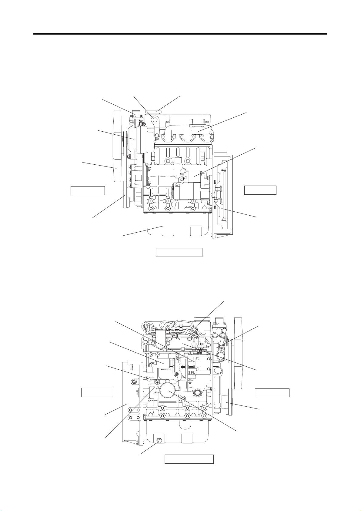
1.1 Outline Drawing
S3L, S3L2
Thermostat
Alternator
Fan
Hanger
Oil filler
Exhaust manifold
Starter
Front end
V belt
Oil pan
Left-hand side
Rear end
Flywheel
Engine LH side view
Fuel injection nozzle
Fuel injection pump
Stop solenoid
Coolant drain plug
Water pump
Inlet cover
1 - 2
Rear end
Flywheel housing
Oil level gauge
Oil drain plug
Right-hand side
Engine RH side view
Front end
Crankshaft pulley
Oil filter
Page 16
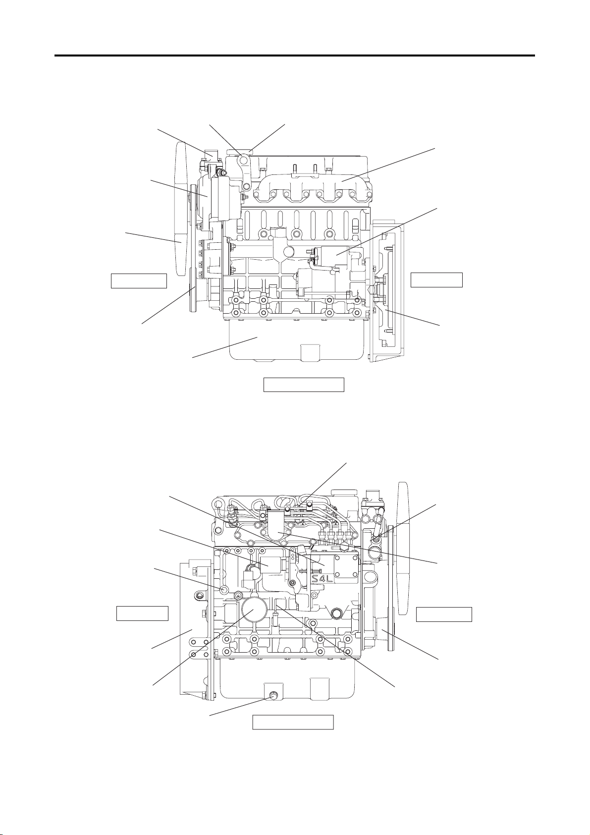
S4L, S4L2
Thermostat
Alternator
Fan
Hanger
GENERAL
Oil filler
Exhaust
manifold
Starter
Fuel injection pump
Coolant drain plug
Front end
V belt
Stop solenoid
Oil pan
Left-hand side
Engine LH side view
Rear end
Flywheel
Fuel injection nozzle
Water pump
Inlet cover
Flywheel housing
Rear end
Oil filter
Oil drain plug
Right-hand side
Engine RH side view
Front end
Crankshaft pulley
Oil level gauge
1 - 3
Page 17
GENERAL
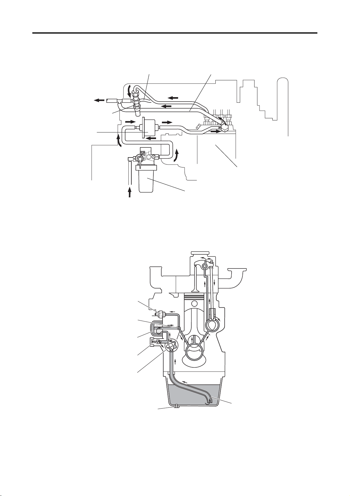
1.2 Fuel System Schematic
To fuel tank
Fuel injection nozzle
Fuel pump
Fuel leak-off pipe
E
P
N
O
Fuel injection pipe
Fuel injection pump
From fuel tank
1.3 Oil System Schematic
Oil pressure switch
Oil main gallery
Oil filter
Relief valve
Fuel filter
Fuel system schematic
1 - 4
Oil pump
Oil drain plug
Oil strainer
Oil system schematic
Page 18
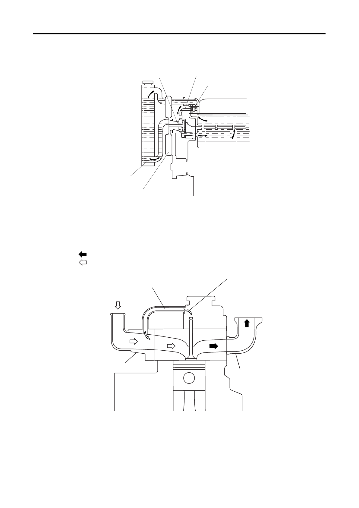
1.4 Cooling System Schematic
Radiator
Water pump
GENERAL
Water bypass valve
Thermostat
Cooling fan
Cooling system schematic
1.5 Inlet / Exhaust System Schematic
Exhaust gas
Intake air
Air breather pipe
(positive crankcase
ventilation)
Intake air
(from air cleaner)
Inlet cover
Blow-by gas
Exhaust gas
(to muffler)
Exhaust manifold
Inlet / exhaust system schematic
1 - 5
Page 19
GENERAL
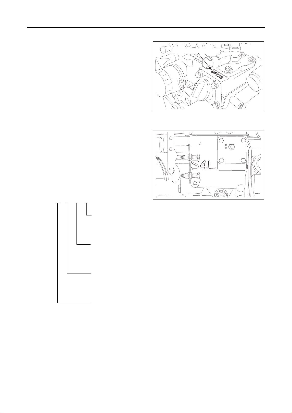
1.6 Engine Serial Number
The engine serial number is stamped on the top
face of the fuel injection pump bracket on the
right-hand side of the cylinder block.
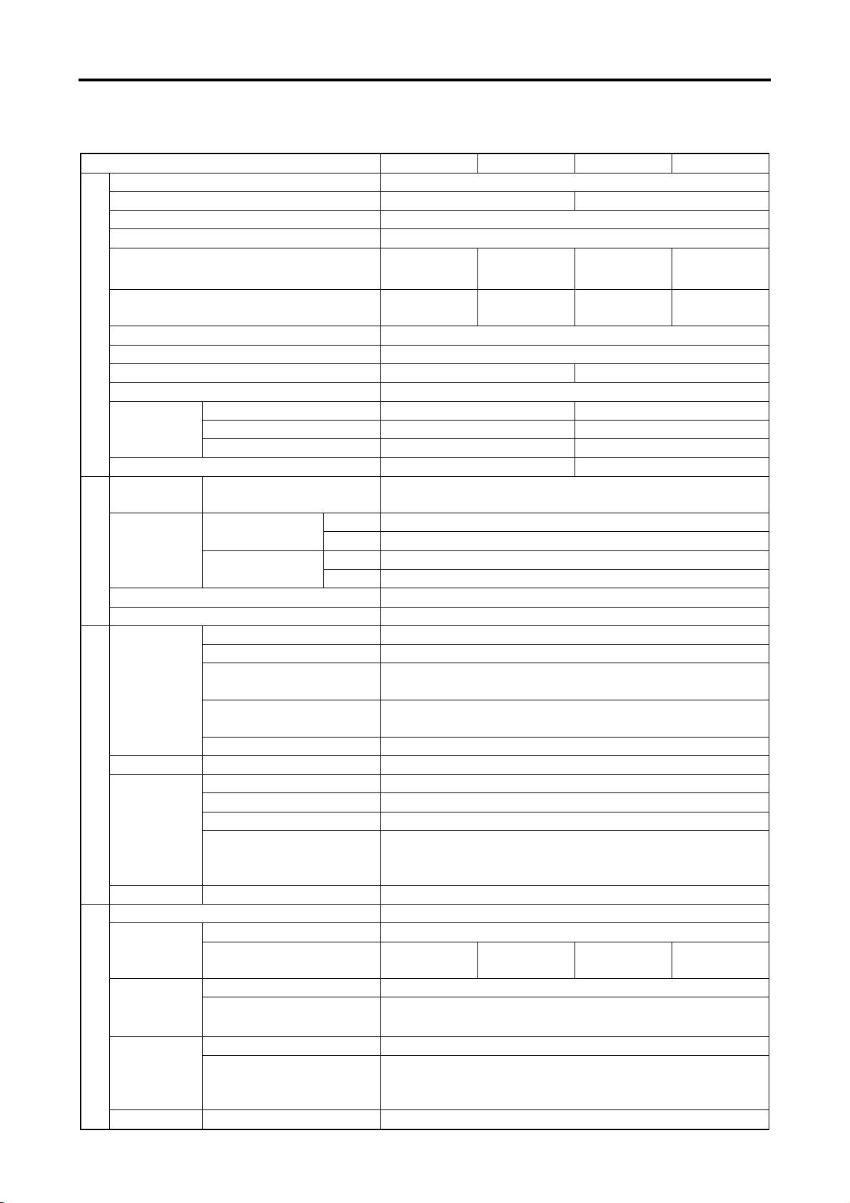
1.7 Engine Model and Application Codes
(1) The engine model code is embossed on the side
of the fuel injection pump mount on the
right-hand side of the cylinder block.
(2) The engine model code consists of the following
alphanumerical digits.
Model coding
(Example) S
4 L 2
Type
(2 = Type 2)
Series
[L = bore size 78 mm (3.07 in.)]
No. of cylinders
(4 = 4 cylinders)
S = Sagamihara Machinery Works
Engine serial number
Engine serial number location
Engine model code
1 - 6
Page 20
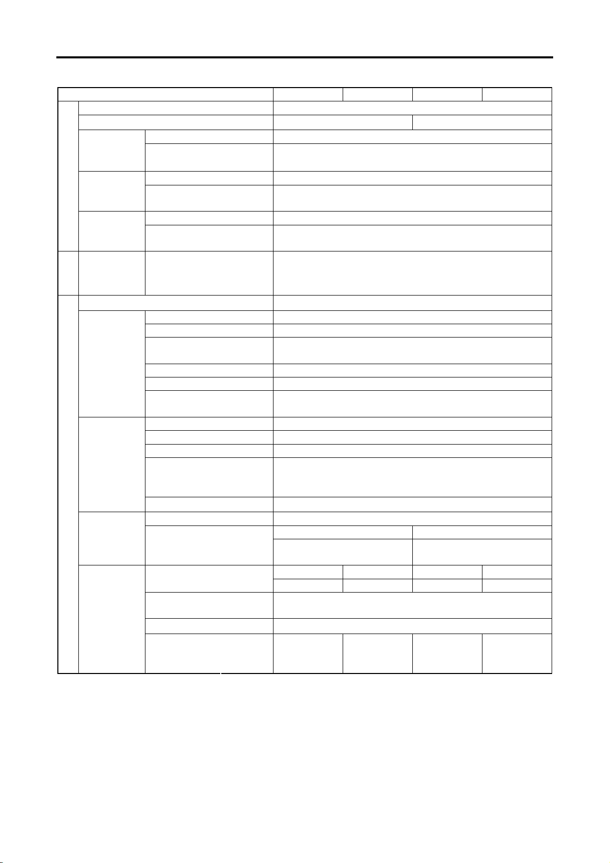
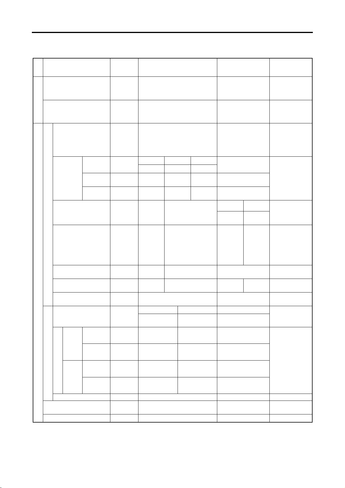
2. Specifications
Engine Type S3L S3L2 S4L S4L2
Type Water-cooled; 4-stroke cycle; Diesel powered
No. of cylinders 3 4
Combustion Swirl chamber type
Valve mechanism Overhead valve type
Cylinder bore×stroke mm (in.)
Total displacement l (U.S. gal)
Compression ratio 22.0 : 1
General
Fuel Diesel fuel (JIS K2204 Special 1 - 3)
78×78.5
(3.07×3.09)
1.125
(0.297)
Firing order 1-3-2 1-3-4-2
Direction of rotation Counterclockwise when viewed from the flywheel end
Overall length mm (in.) 536 (21.10) 620 (24.40)
Dimensions
Overall width mm (in.) 433 (17.04) 433 (17.04)
Overall height mm (in.) 572 (22.52) 572 (22.52)
Dry mass kg (lb) 135 (297.6) 155 (341.7)
Piston ring No. of rings
Va l ve
Inlet valve
timing
(hot engine)
Engine mounting 4 mounts
Engine main parts
Starting method Starter
Exhaust valve
Open BTDC 15°
Close ABDC 41°
Open BBDC 54°
Close ATDC 10°
Type Bosch M
Manufacturer DENSO
Injection
pump
Plunger
diameter
MS retard
mm (in.)
(crank angle)
Cam lift mm(in.) 15 (0.59)
Governor Governing method Centrifugal fly-weight type
Type Throttle nozzle
Fuel system
Injection
nozzle
Manufacturer Bosch Automotive Systems Corporation
Spray angle mm (in.) 15°
Opening
pressure
MPa
(kgf/cm
[psi]
2
)
Fuel filter Type Paper-element cartridge; Separate type w/ cock
Lubrication method Forced circulation (pressure feed by trochoid pump)
Grade CD Class (API Classification)
Engine oil
Capacity
(entire engine)
l (U.S. gal)
3.7 (1.0) 4.2 (1.1) 5.4 (1.4) 6.0 (1.6)
Type Gear pump
Oil pump
Oil system
Relief valve
Displacement
Type Piston valve
Opening
pressure
l (U.S. gal)
/min
MPa
(kgf/cm
2
)
[psi]
Oil filter Type Paper element (spin-on type)
78×92
(3.07×3.62)
1.318
(0.348)
78×78.5
(3.07×3.09)
1.500
(0.396)
Compression ring :2
Oil ring (w/expander) : 1
φ5.5 (0.21)
8°
14.22 to 15.00 (145 to 153)
[2062 to 2176]
18 (4.8)
0.35±0.05 (3.6±0.5)
[51±7]
GENERAL
78×92
(3.07×3.62)
1.758
(0.464)
1 - 7
Page 21
GENERAL
I
l
t
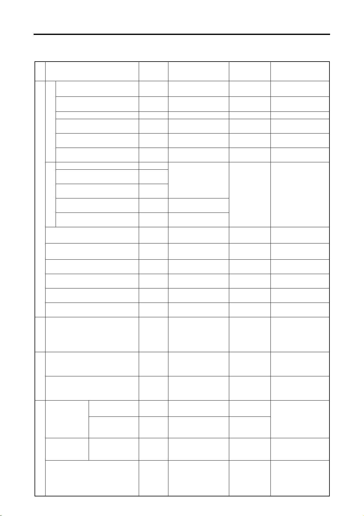
Engine Type S3L S3L2 S4L S4L2
Cooling method Water-cooled, forced circulation
Capacity (engine proper)
l (U.S. gal)
1.8 (0.5) 2.5 (0.7)
Type Centrifugal pump
Water pu m p
Displacement
l (U.S. gal)
/min
30 (8.0) up (@ 2000 min
Type Wax
Thermostat
Cooling system
Cooling fan
Opening
temperature
℃ (°F)82±1.5 (179.6±2.7)
Type Pusher suction (PP fan)
No. of blades / OD
mm (in.)
5 / 340 (13.39), 6 / 320 (12.6), 6 / 340 (13.39),
6 / 360 (14.17), 6 / 380 (14.96), 7 / 380 (14.96)
e
Air cleaner Type Paper element
n
system
Voltage - Polarity
12 V - Θ ground, 24 V - Θ ground
Type M001T68281, M008T70471A, M008T81071A
Manufacturer Mitsubishi Electric Corporation
Starter
Pinion
engagement
Output V-kW 12 V-1.7, 12 V-2.0, 24 V-3.2
Pinion shift (reduction)
No. of units 1
Reduction ratio
(pinion / ring gear)
13 / 120
Type 3-phase alternator w/ built-in IC regulator
Manufacturer Mitsubishi Electric Corporation
Output V-A 12-50, 24-25
Alternator
Speed at which
rated voltage is
min
-1
5000 (@ 13.5 V, 47 A), 5000 (@ 27.0 V, 22 A)
generated
Regulated voltage V
Electrical system
Glow plug
Type Sheathed plug
Rated voltage current
voltage
Stop
solenoid
Insulation resistance
Stroke mm (in.)
Working
ambient
temperature
V-A
V
℃ (°F)
(30-second application)
12 V-ETR 12 V-ETS 24 V-ETR 24 V-ETS Operating
8 or less 10 to 15 16 or less 20 to 30
-40 to 120
(-40 to 248)
14.7±0.3 (12-50), 26.5±0.5 (24-25)
12 V plug 24 V plug
10.5-9.7
(25-second application)
100 MΩ or more at DC500 V
(at ordinary temperature and humidity)
13.5±0.5 (0.53±0.01)
-30 to 120
(-22 to 248)
-40 to 120
(-40 to 248)
-1
engine speed)
22.5-5
-30 to 120
(-22 to 248)
1 - 8
Page 22

3. Disassembly / Reassembly Notes
This Service Manual specifies various procedures
recommended by Mitsubishi Heavy Industries, Ltd. for
servicing Mitsubishi diesel engines. These procedures
include, wherever appropriate, required special tools
and related safety precautions.
The instructions provided in this manual, however,
cannot fully guarantee safety as potential risks beyond
ordinary imagination are hidden everywhere.
When conduct any work, the following points should
also be observed in addition to the instructions this
manual.
3.1 Disassembly
(1) Use tools and equipment that are appropriate for
the work being carried out.
(2) Whenever necessary, use workbenches to work
on or sort parts out. Disassemble in accordance
with the disassembly sequence given in the
manual.
(3) As parts are disassembled, place them neatly in
the order of removal to eliminate missing parts
on reassembly.
(4) During disassembly, note the assembly marks.
Remember to respect these marks on reassembly.
Whenever appropriate, put additional assembly
marks to aid reassembly.
(5) Before and during disassembly as well as during
subsequent washing, carefully check for any
abnormality or other fault which otherwise may
likely remain unnoticed afterwards.
(6) Pay sufficient attention to ensure safety,
especially when lifting or carrying heavy
components and parts. (Use a jack or a chain
block as required.)
3.2 Reassembly
(1) Parts excluding oil seals, O-rings, rubber sheets,
etc. should be thoroughly washed in wash oil and
completely dried using compressed air.
(2) Use appropriate tools and equipment.
(3) Use good-quality oil and grease. Never fail to
apply oil, grease, sealant and adhesive to the
relevant locations if so instructed in the manual.
GENERAL
1 - 9
Page 23

GENERAL
(4) Tighten hardware to the specified torque, if
provided in the manual. Be sure to use a torque
wrench.
(5) Gaskets, packing and O-rings should be replaced
with new parts unless specified otherwise.
1 - 10
Page 24

SERVICE STANDARDS
1. Service Standards Table····································································· 1 -12
2. Tightening Torques Table···································································· 1 -16
2.1 Major Bolts and Nuts ··········································································· 1 -16
2.2 Standard Bolts and Nuts······································································· 1 -17
2.3 Standard Eyebolts··············································································· 1 -17
2.4 Standard Union Nuts ··········································································· 1 -18
2.5 Taper Bolts ························································································ 1 -18
3. Sealants List······················································································· 1 -19
Page 25

SERVICE STANDARDS
g
g
1. Service Standards Table
Unit: mm (in.)
Item
Group
Max. speed
(based on the rated speed)
Min. speed
Compression pressure
(at 290 min
-1
)
Rated speed
pressure
Engine oil
Low idle speed
Inlet valve
Engine general
Valve timing [with
2 mm (0.079 in.)
clearance on the
valve side; cold
engine]
open
Inlet valve
closed
Exhaust valve
open
Exhaust valve
closed
Valve clearance
Inlet valve 0.25 (0.01)
Exhaust valve 0.25 (0.01)
Fuel injection timing (BTDC)
Rocker arm inner diameter
Rocker shaft diameter
Rocker
Arm-to-shaft clearance
(oil clearance)
Inlet
Valve stem diameter
Exhaust
Valve guide inner
diameter
Va l ve
Valve stem-to-guide
Engine main parts
clearance
Inlet
Exhaust
Inlet
Exhaust
Valve seat angle
Valve head sinkage 0
Valve seat width
Valve head margin
Valve seat and valve
Installed valve guide protrusion
Nominal
value
φ19
(0.749)
φ19
(0.749)
φ6.6
(0.260)
φ6.6
(0.260)
φ6.6
(0.260)
φ6.6
(0.260)
45
°
1.6
(0.063)
1.5
(0.0591)
10
(0.394)
Standard value Limit Remarks
+30
2700
1000±25 min
-10
min-1
-1
2.9 MPa (30 kgf/cm
[421 psi]
or above
2
)
2.6 MPa
(27 kgf/cm
2
[377 psi]
or less
Both oil and coolant
)
temperatures at 20 to
30℃ (68 to 86°F)
0.29 to 0.39 MPa
(3.0 to 4.0 kgf/cm2)
[42.07 to 56.57 psi]
0.098 MPa
(1.0 kgf/cm
2
)
Oil temperature at
60 to 95℃ (140 to
194°F)
[14.22 psi]
BTDC 15
°
The theoretical valve
ABDC 41
°
timing figures for
inspection vary from
BBDC 54
°
the actual valve
timing.
ATD C 10
°
Cold engine
17°
18.910 to 18.930
(0.7450 to 0.7458)
18.880 to 18.898
(0.7438 to 0.7445)
0.012 to 0.050
(0.0004
to 0.0019)
6.565 to 6.580
(0.2586 to 0.2592)
6.530 to 6.550
(0.2572 to 0.2580)
6.600 to 6.615
(0.2600 to 0.2606)
6.600 to 6.615
(0.2600 to 0.2606)
0.020 to 0.050
(0.0008 to 0.0020)
0.050 to 0.085
(0.0020 to 0.0033)
0.25 to 0.75
(0.0098 to 0.0295)
1.30 to 1.80
(0.0512 to 0.0709)
1.35 to 1.65
(0.0531 to 0.0650)
9.5 to 10.5
(0.3743 to 0.4137)
―
―
0.200
(0.0079)
6.500
(0.256)
6.500
(0.256)
0.100
(0.004)
0.150
(0.006)
Valve seat width
1.5
(0.0591)
2.5
(0.0985)
0.5
(0.0197)
―
Replace rocker arm.
Replace valve and
valve guide.
Val v e
seat
Valve head
angle
sinka
Va l ve
head
in
mar
e
1 - 12
Page 26

SERVICE STANDARDS
Unit: mm (in.)
Group
Item
Nominal
value
Standard value Limit Remarks
Free length 47 (1.85) 46 (1.81)
θ
Squareness
39.0 (1.536)/
131 to 145
(13.3 to 14.7)
[29 to 33]
Valve spring
Installed length / load
mm (in.)/N (kgf) [lbf]
Push rod Bend
Cylinder head
Cylinder block top face
distortion
Cylinder
Bore
Bottom face
distortion
φ78
(3.07)
78.0
Out of roundness
STD
Diameter
0.25 OS
0.50 OS
Max. allowable variation in
weight among pistons on the
Piston
same engine
Engine main parts
Piston pin diameter
Piston pin-to-boss clearance
Piston-to-cylinder clearance
No. 1 ring
Piston
ring-to-groove
No. 2 ring
clearance
Oil ring
Piston ring
Piston ring gap
No. 1 ring
No. 2 ring
78.00
(3.07)
78.25
(3.08)
78.50
(3.09)
φ23
(0.9062)
±5 g (0.177 oz)
22.944 to 23.000
(0.9039 to 0.9062)
(0.0002 to 0.0007)
(0.0014 to 0.0034)
(0.0035 to 0.0043)
(0.0028 to 0.0043)
(0.0012 to 0.0028)
Oil ring
Bend and twist
rod
End play
Connecting
θ=2.0°
Δ=0.2
(0.0079)
Lf=47
(1.8518)
30.1 (1.185)/
279 to 309
(28.5 to 31.5)
[63 to 69]
―
0.05 (0.002)
or less
0.05 (0.002)
or less
+0.03
0
(3.07
+0.0012
0
±0.01 (0.0004)
or less
77.93 to 77.95
(3.070 to 3.071)
78.18 to 78.20
(3.080 to 3.081)
78.43 to 78.45
(3.090 to 3.090)
or less
0.006 to 0.018
0.035 to 0.086
0.09 to 0.11
0.07 to 0.11
0.03 to 0.07
0.15 to 0.30
(0.006 to 0.012)
0.15 to 0.35
(0.006 to 0.014)
0.20 to 0.40
(0.008 to 0.016)
0.05/100
(0.002/3.940)
0.10 to 0.35
(0.004 to 0.014)
△= 0.5
(0.0197)
across the
entire length
0.3 (0.011) Replace
0.10 (0.004) Correct
0.10 (0.004) Correct
78.2 (3.08) Bore or replace
)
(0.006/3.940)
-15 %
―
77.80
(3.065)
78.05
(3.075)
78.30
(3.085)
―
―
0.050
(0.002)
0.300
(0.012)
0.300
(0.012)
0.200
(0.008)
0.200
(0.008)
1.50
(0.06)
0.15/100
0.50
(0.020)
Bore or replace
Replace piston ring
Replace
Replace connecting
rod
1 - 13
Page 27
SERVICE STANDARDS
Unit: mm (in.)
Item
Group
Crank journal diameter (STD)
Crank pin diameter
Nominal
value
φ52
(2.0488)
φ48
(1.8912)
Standard value Limit Remarks
51.985 to 52.000
(2.0482 to 2.0488)
47.950 to 47.964
(1.8892 to 1.8897)
Crankshaft bend 0.025 (0.0010)
Main bearings oil clearance
Crankshaft
Connecting rod bearings oil
clearance
End play
0.030 to 0.077
(0.0012 to 0.0030)
0.025 to 0.072
(0.0010 to 0.0028)
0.050 to 0.175
(0.0020 to 0.0069)
Crank gear to idler gear
Idler gear to valve camshaft
gear
Idler gear to pump camshaft
gear
Valve camshaft gear to PTO
gear
Pump camshaft gear to oil
Timing gear backlash
Engine main parts
pump gear
Camshaft cam height
(including lobe)
Fuel injection pump shaft cam
height (including lobe)
Flywheel flatness
0.040 to 0.120
(0.0015 to 0.0047)
0.080 to 0.190
(0.0032 to 0.0075)
0.070 to 0.200
(0.0028 to 0.0079)
(1.4073±0.0394)
(1.7336±0.0039)
0.150 (0.0059)
Tappet-to-guide clearance
Camshaft journal-to-bushing
clearance
Idler gear-to-shaft clearance
0.050 to 0.125
(0.0020 to 0.0049)
0.020 to 0.070
(0.0008 to 0.0028)
35.720±0.1
44±0.1
or less
―
―
―
0.050 (0.0020)
0.100
(0.0040)
0.150
(0.0059)
0.500
(0.0197)
0.300
(0.0120)
34.720
(1.3679)
43
(1.6942)
0.500
(0.0197)
0.150
(0.0059)
0.150
(0.0059)
0.200
(0.0079)
Correct or replace
Replace main
bearings
Replace connecting
rod bearings
Replace flanged No.
3 main bearings
Replace
Replace
Replace
Correct
Replace tappet
Replace bushing
Replace idler gear or
idler shaft
Injection valve opening pressure
MPa (kgf/cm
Fuel system
Relief valve opening pressure
MPa (kgf/cm
Oil pressure switch closing pressure
Oil system
MPa (kgf/cm
Valve opening
temperature
Thermostat
8 mm (0.32 in.)
valve lift
temperature
Thermoswitch
Fan belt deflection {when pressed
Cooling system
with a force of approx. 98 N (10
At 111±3.5℃
(231.8±6.3°F)
kgf) [22] between crankshaft and
alternator pulleys and between
crankshaft and fan pulleys}
1 - 14
2
) [psi]
2
) [psi]
2
) [psi]
14.22
(145)
[2062]
14.22 to 15.00
(145 to 153)
[2062 to 2176]
0.35±0.05
(3.5±0.5)
[50±7.2]
0.05±0.01
(0.5±0.1)
[7±1.4]
82±1.5℃
(179.6±2.7°F)
95℃
(203°F)
30 MΩ
[when dipped in oil of
105℃ (221°F)]
10 to 12
(0.4 to 0.5)
―
―
―
―
―
―
―
Adjust with washer
Replace
Replace
Replace
Replace
Replace
Page 28
SERVICE STANDARDS
I
l
t
d
h
t
y
O
h
i
i
(
)
Unit: mm (in.)
Item
Group
Paper-element type air
aus
cleaner
ex
stems
Inlet / exhaust manifold
s
an
e
mounting face distortion
n
Pinion gap
No-load
characteristics
Brush length
Starter
Brush spring load
Commutator radial
runout
Commutator diameter
Electrical system
Mica undercutting
depth
IC regulator
controlled voltage
[at 20℃ (68°F)]
2500
min
or
-1
cs
st
less
aracter
Alternator
5000
when hot
-1
min
utput c
or
less
Nominal
value
Standard value Limit Remarks
Clean every 100 hours
―
0.5 to 2.0
(0.02 to 0.08)
Term inal
voltage
Current
Rotation
speed
M001T68281 M008T70471A M008T81071A
11 V 11 V 23 V
110 A
or less
2400
min
16.5
(0.65)
130 A
or less
3600
-1
min-1
80 A
or less
3000
min-1
18.0
(0.71)
17.5 to
23.7 N
(1.78 to
2.41 kgf)
[3.9 to 5.3
29.4 to 39.2 N
(3.0 to 4.0 kgf)
[6.6 to 8.8 lbf]
lbf]
0.05
(0.002)
29.4
(1.16)
0.03
(0.001)
32.0
(1.26)
0.5
(0.02)
A007T02071C A007TA8571
Term inal
voltage
13.5 V 27.0 V
14.7±0.3 V 28.5±0.5 V
Current 32 A or above 18 A or above
Term inal
voltage
13.5 V 27.0 V
Current 47 A or above 22 A or above
Replace every
500 hours
0.15 (0.006)
or less
―
―
―
―
M001T68281
10.0
(0.39)
6.90 N
(0.70 kgf)
[1.6 lbf]
0.10
(0.004)
28.8
(1.13)
0.2
(0.01)
―
―
―
―
―
M008T70471A,
M008T81071A
11.0
(0.43)
13.7 N
(1.40 kgf)
[3.1 lbf]
31.4
(1.24)
Grind or
replace
Adjust with
packing
Inspect
Replace
Replace
Correct or
replace
Replace
Correct
Brush length 18.5 (0.73) 5.0 (0.20) Replace
Clearance between stop
solenoid plunger and rack
Glow plug resistance 0.55 Ω
0.15 to 0.20
(0.006 to 0.008)
Correct
―
Replace
1 - 15
Page 29
SERVICE STANDARDS
2. Tightening Torques Table
2.1 Major Bolts and Nuts
Thread
Fittings
Engine proper
Cylinder head bolt
Rocker cover bolt
Rocker shaft bracket bolt
Thrust plate bolt
Main bearing cap bolt
Connecting rod cap nut
Flywheel bolt
Crankshaft pulley nut
Rear plate mounting bolt
Fuel system
Hollow screw
(fuel injection pump)
Delivery valve holder
(fuel injection pump)
Air bleeder plug
(fuel injection pump)
Nozzle retaining nut
Nozzle holder IDI
Fuel injection pipe nut
Fuel leak-off pipe nut
Sliding sleeve shaft
Torque spring set special nut
Oil system
Oil relief valve
Oil pan drain plug
Oil filter
Oil pressure switch PT1/8 7.85 to 11.8 0.8 to 1.2 5.8 to 8.7
Oil pan mounting bolt
Oil strainer nut
Cooling system
Thermoswitch
Thermostat cover bolt
Thermo case bolt
Inlet and exhaust systems
Inlet cover bolt
Exhaust manifold bolt
Electrical system
Starter terminal B
Stop solenoid fixing nut
Stop solenoid blind plug
Glow plug
IDI
diameter
×pitch
(mm)
M10×1.75
M8×1.25
M8×1.25
M8×1.25
M10×1.25
M9×1.0
M12×1.25
M18×1.5
M12×1.25
M14×1.5
―
M8×1.25
M16×0.75
M20×1.5
M12×1.5
M12×1.5
M10×1.25
M12×1.0
M22×1.5
M14×1.5
M20×1.5
M8×1.25
M16×1.5
M16×1.5
M8×1.25
M16×1.5
M8×1.25
M8×1.25
M8×1.25
M30×1.5
M30×1.5
M10×1.25
N・m kgf・m lbf・ft
83.4 to 93.2 8.5 to 9.5 61.5 to 68.7
9.81 to 12.7 1.0 to 1.3 7.2 to 9.4
9.81 to 19.6 1.0 to 2.0 7.2 to 14.5
9.8 to 11.8 1.0 to 1.2 7.2 to 8.7
49.0 to 53.9 5.0 to 5.5 36.2 to 39.8
32.4 to 37.3 3.3 to 3.8 23.9 to 27.5
127 to 137 13.0 to 14.0 94.0 to 101.3
147 to 196 15.0 to 20.0 108.5 to 144.6
53.9 to 73.5 5.5 to 7.5 39.8 to 54.2 Equivalent to 7T
19.6 to 24.5 2.0 to 2.5 14.5 to 18.1
39.2 to 49.0 4.0 to 5.0 28.9 to 36.1
9.81 to 13.7 1.0 to 1.4 7.2 to 10.1
34.3 to 39.2 3.5 to 4.0 25.3 to 28.9
49.0 to 58.8 5.0 to 6.0 36.2 to 43.4
24.5 to 34.3 2.5 to 3.5 18.1 to 25.3
20.6 to 24.5 2.1 to 2.5 15.2 to 18.1
29.4 to 41.2 3.0 to 4.2 21.7 to 30.4
14.7 to 24.5 1.5 to 2.5 10.8 to 18.1
44.1 to 53.9 4.5 to 5.5 32.5 to 39.8
34.3 to 44.1 3.5 to 4.5 25.3 to 32.5
10.8 to 12.7 1.1 to 1.3 8.0 to 9.4
9.80 to 12.7 1.0 to 1.3 7.2 to 9.4 Equivalent to 4T
24.5 to 29.4 2.5 to 3.0 18.1 to 21.7
18.6 to 26.5 1.9 to 2.7 13.7 to 19.6
16 to 20 1.6 to 2.0 11.8 to 14.8
39.2 to 49.0 4.0 to 5.0 28.9 to 36.1
14.7 to 21.6 1.5 to 2.2 10.8 to 15.9
14.7 to 21.6 1.5 to 2.2 10.8 to 15.9
9.81 to 11.8 1.0 to 1.2 7.2 to 8.7
39.2 to 49.0 4.0 to 5.0 28.9 to 36.1
39.2 to 49.0 4.0 to 5.0 28.9 to 36.1
14.7 to 19.6 1.5 to 2.0 10.8 to 14.5
Tightening torque
Remarks
1 - 16
Page 30
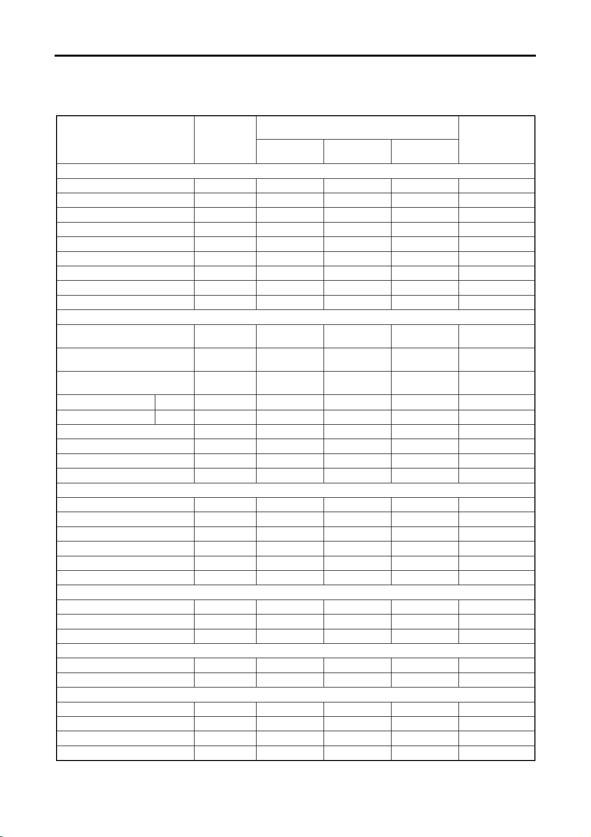
2.2 Standard Bolts and Nuts
Thread
diameter
×pitch (mm)
N・m kgf・m lbf・ft N・m kgf・m lbf・ft
SERVICE STANDARDS
4T 7T
M6×1.0
M8×1.25
M10×1.25
M12×1.25
2.94 to 4.90 0.3 to 0.5 2.2 to 3.6 7.85 to 9.80 0.8 to 1.0 5.8 to 7.2
9.80 to 12.7 1.0 to 1.3 7.2 to 9.4 14.7 to 21.6 1.5 to 2.2 10.8 to 15.9
17.7 to 24.5 1.8 to 2.5 0.7 to 1.0 29.4 to 41.2 3.0 to 4.2 21.7 to 30.4
29.4 to 41.2 3.0 to 4.2 21.7 to 30.4 53.9 to 73.5 5.5 to 7.5 39.8 to 54.2
Note: (a) The above table shows the tightening torques for standard bolts and nuts.
(b) The values in the table apply when tightened together with spring washers.
(c) The above table shows standard values, for which a tolerance of ±10% is allowed.
(d) Unless otherwise specified, standard bolts and nuts should be tightened to the torques in the table.
(e) Do not apply oil to threaded portions (Tighten under dry conditions).
2.3 Standard Eyebolts
Thread diameter
×pitch (mm)
M8×1.25 8±1 0.8±0.1
M10×1.25 15±2 1.5±0.2
M12×1.25 25±3 2.5±0.3
M14×1.5 34±4 3.5±0.4
M16×1.5 44±5 4.5±0.5
M18×1.5 74±5 7.5±0.5
M20×1.5 98±10 10.0±1.0
M24×1.5 147±15 15.0±1.5
M27×1.5 226±20 23.0±2.0
(Dry conditions)
N・m kgf・m lbf・ft
Property class
5.9±0.7
11.1±1.5
18.4±2.2
25.1±3.0
32.5±3.7
54.6±3.7
72.3±7.4
108.4±10.8
166.7±14.8
1 - 17
Page 31

SERVICE STANDARDS
2.4 Standard Union Nuts
Nominal
diameter
63
Cap nut size
M14×1.5
N・m kgf・m lbf・ft
39 4 28.8
80
100
120
150
180
200
220
254
(Dry conditions)
M16×1.5
M20×1.5
M22×1.5
M27×1.5
M30×1.5
M30×1.5
M33×1.5
M36×1.5
49 5 36.1
78 8 57.5
98 10 72.3
157 16 115.8
196 20 144.6
196 20 144.6
245 25 180.7
294 30 216.8
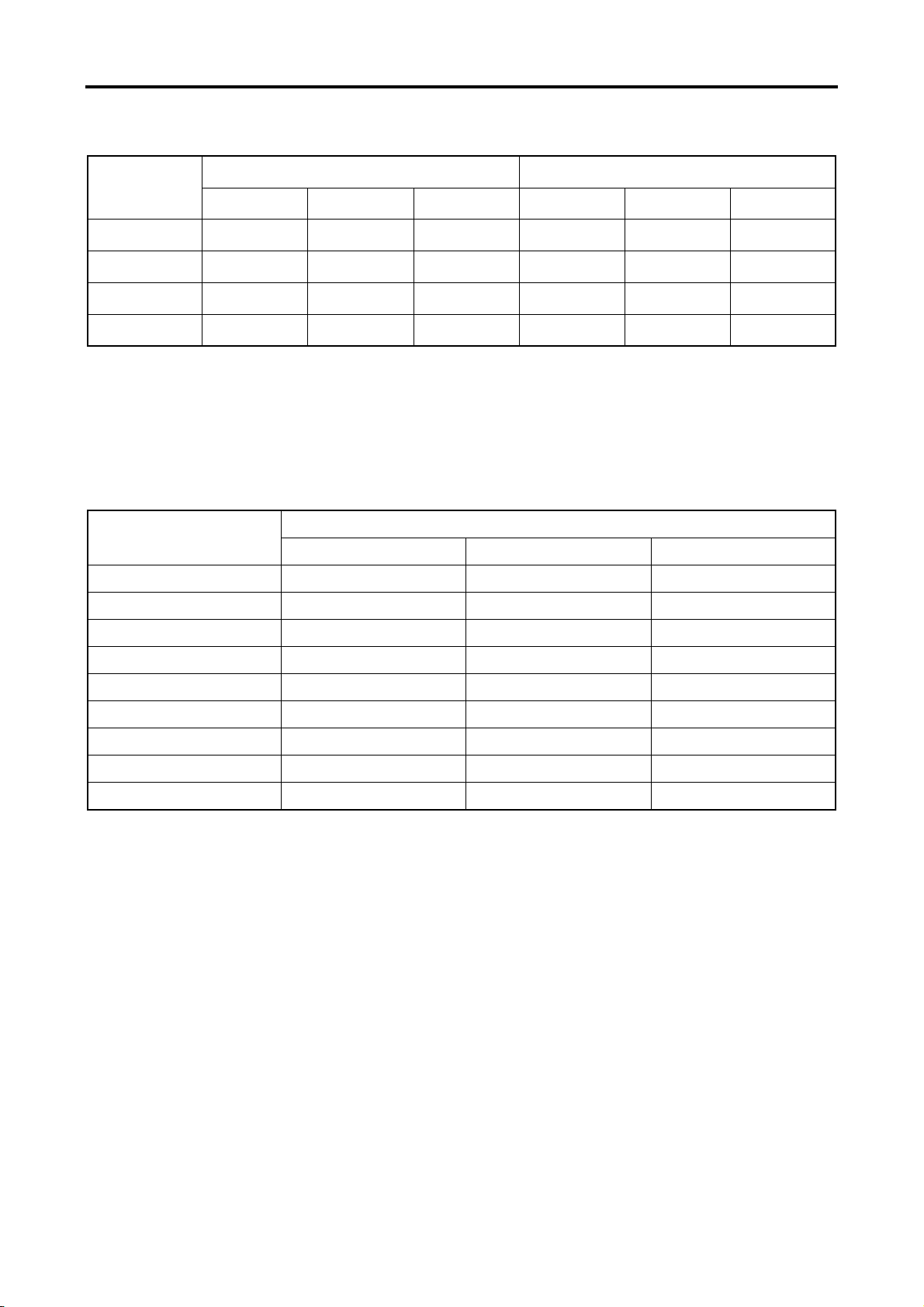
2.5 Taper Bolts
Size
NPTF1/16 4.90 to 7.85 0.5 to 0.8 3.6 to 5.8 7.85 to 11.8 0.8 to 1.2 5.8 to 8.7
PT1/8 7.85 to 11.8 0.8 to 1.2 5.8 to 8.7 14.7 to 21.6 1.5 to 2.2 10.8 to 15.9
PT1/4, NPTF1/4 19.6 to 29.4 2.0 to 3.0 14.5 to 21.7 34.3 to 44.1 3.5 to 4.5 25.3 to 32.5
PT3/8 ― ― ― 53.9 to 73.5 5.5 to 7.5 39.8 to 54.2
Tightening into aluminum Tightening into iron
N・m kgf・m lbf・ft N・m kgf・m lbf・ft
1 - 18
Page 32

3. Sealants List
Stop solenoid ThreeBond 1212 Governor case
Water drain joint
Threaded part
Oil pressure switch
Torque spring set ThreeBond 1212 Governor case
Sealing item Sealant
ThreeBond 1102 Block
Mating
component
Cylinder block
SERVICE STANDARDS
Applied location
Threaded portion
Press - fit part
Other
Sealing cap
Expansion plug
Oil level gauge guide
Side seal
Main bearing cap
(front and rear)
Oil pan
ThreeBond 1102
ThreeBond 1212
ThreeBond
1207C
Cylinder head
Cylinder head,
Cylinder block
Cylinder block
Cylinder block,
Main bearing cap
Cylinder block
Holes in the cylinder
head and block
Outer periphery
Contact faces with the
cylinder block
Oil pan sealing face
1 - 19
Page 33

SERVICE STANDARDS
1 - 20
Page 34

TOOLS LIST
1. General Tools····················································································· 1 -22
2. Special Tools······················································································· 1 -23
Page 35

TOOLS LIST
1. General Tools
No. Description Part number Remarks
Tool set MM413-900
―
Spanner MK96008010
①
Spanner MK96012014
②
Spanner MK96017019
③
Screwdriver MM300110 (-)
④
Tool bag MM300783
⑤
Consists of items ① to ⑤
Width across flats [8×10 mm (0.31×0.39 in.)]
Width across flats [12×14 mm (0.47×0.55 in.)]
Width across flats [17×19 mm (0.67×0.75 in.)]
1 - 22
Page 36

TOOLS LIST
2. Special Tools
Description Part number Shape Application
Piston Pin
Setting T ool
Camshaft Bushing
Installer
Compression Gauge
Adapter
Oil Pressure Switch
Socket Wrench
(26)
31A91-00100
ST332340
ST332270
MD998054
Piston pin
removal / installation
Punching / press-fitting of
front camshaft bushing
Compression measuring
Oil pressure switch
removal / installation
Piston Ring Pliers 31391-12900
Piston ring
removal / installation
1 - 23
Page 37

TOOLS LIST
1 - 24
Page 38

OVERHAUL TIMING
1. Identifying the Timing for Overhaul······················································ 1-26
2. Measuring the Compression Pressure················································1-27
Page 39

OVERHAUL TIMING
1. Identifying the Timing for Overhaul
Generally, when the compression pressure has dropped below the specified value, overhaul of the engine
needs to be considered. Other parameters should also be considered in making the decision as to whether or
not to overhaul the engine, such as engine oil consumption and blow-by gas volume.
Some of the phenomena that may suggest, but are not necessarily the criteria for, the need to overhaul the
engine include reduced power, increased fuel consumption, oil pressure drop, difficulty in starting and higher
noise level.
More specifically, reduction in compression pressure creates various types of phenomena in various
combinations, and this is why it is difficult to make a correct decision. Typical phenomena include:
(a) Reduced power
(b) Increased fuel consumption
(c) Increased engine oil consumption
(d) Increased blow-by gas through the breather due to worn parts such as cylinder liners and pistons
(e) Increased blow-by gas due to poor seating of inlet / exhaust valves
(f) Poor starting
(g) Increased noise levels of various engine parts
(h) Abnormal color of exhaust gas after warm-up
Some of those listed above are directly related to the deterioration of the engine and some are not.
Items (b) and (f) are heavily influenced by fuel injection pump displacement, fuel injection timing, wearing
of plungers, nozzle conditions, and conditions of electrical equipment such as battery and starter.
The most reliable criterion for engine overhaul is reduced compression pressure due to the wearing of
cylinder liners and pistons [item (d)]. This should be combined with other items for comprehensive review
to reach a rational conclusion.
1 - 26
Page 40

2. Measuring the Compression Pressure
(1) Move the control lever to STOP position.
(2) Remove the glow plugs from all cylinders.
Install the special tool Compression Gauge
Adapter and a compression gauge onto the
cylinder being measured.
Special tool Part number
Compression Gauge Adapter ST332270
(3) While cranking the engine with the starter, read
the compression gauge. Note the reading at
which the gauge needle stabilizes.
(4) If the measured value is at or below the limit,
overhaul the engine.
(a) Measure all cylinders for compression
pressure. Do not measure only one
cylinder and make assumption about the
other cylinders as this will lead to a wrong
conclusion.
(b) Compression pressure varies depending
on the engine speed. Keep the specified
engine speed when measuring the
compression pressure.
OVERHAUL TIMING
Compression
gauge
Compression
gauge adapter
Measuring the compression pressure
Standard value Limit
Engine speed 290 min-1
Compression
pressure
Tolerable
difference
between
cylinders
2.9 MPa
(30 kgf/cm
[421 psi]
0.29 MPa
(3.0 kgf/cm
[42 psi]
or less
2
)
2
)
2.6 MPa
(27 kgf/cm2)
[377 psi]
It is important to regularly check the
compression pressure so that you can tell the
difference.
・ New or overhauled engines have slightly
higher compression pressure.
・ The compression pressure settles to the
standard value as the piston rings and
valve seats fit in.
・ As wear progresses further, the
compression pressure drops.
1 - 27
Page 41

OVERHAUL TIMING
1 - 28
Page 42

REMOVAL PREPARATIONS
1. Preparations························································································ 1-30
1.1 Removing the Electric Wiring ································································· 1-30
1.2 Draining the Coolant············································································· 1-30
1.3 Draining the Engine Oil ········································································· 1-30
Page 43

REMOVAL PREPARATIONS
t
1. Preparations
1.1 Removing the Electric Wiring
Remove the wiring harnesses from the following
equipment.
Before removal, attach mating tags etc. onto the
terminals to aid reassembly.
・Starter
・Switches
1.2 Draining the Coolant
Loosen the coolant drain plug on the right-hand
side face of the cylinder block to drain coolant
from the engine.
1.3 Draining the Engine Oil
Remove the engine oil drain plug from the oil
pan to drain the engine oil.
Install and tighten the drain plug to the specified
torque.
Oil pan capacity: 3.7 to 6.0 l
(1.0 to 1.6 U.S. gal)
Do not touch the engine oil which may be
extremely hot as it can cause burns.
Starter
Starter
wiring
Retaining bol
Removing the electric wiring
Drain plug
Coolant drain cock
Tightening torqe:
34.3 to 44.1N㨯m
Drain piug
(3.5 to 4.5kgf㨯m)
[25.3 to 32.5 lbf㨯ft]
Drain plug on the oil pan
1 - 30
Page 44

ENGINE MAIN PARTS - DISASSEMBLY
1. Cylinder Head, Valve Mechanism························································ 2 - 2
1.1 Removing the rocker shaft assembly······················································· 2 - 3
1.2 Disassembling the rocker shaft assembly················································· 2 - 3
1.3 Removing the cylinder head bolts ··························································· 2 - 3
1.4 Removing the cylinder head assembly····················································· 2 - 4
1.5 Removing the valves and valve springs ··················································· 2 - 4
1.6 Removing the valve stem seals ······························································ 2 - 4
2. Flywheel, Timing Gear, Camshaft························································ 2 - 5
2.1 Removing the flywheel·········································································· 2 - 7
2.2 Removing the flywheel housing ······························································ 2 - 7
2.3 Removing the rear plate········································································ 2 - 8
2.4 Removing the oil seal case···································································· 2 - 8
2.5 Removing the tappets··········································································· 2 - 8
2.6 Removing the crankshaft pulley······························································ 2 - 8
2.7 Removing the timing gear case ······························································ 2 - 9
2.8 Measuring the timing gear backlash ························································ 2 - 9
2.9 Removing the idler gear······································································· 2 -10
2.10 Removing the camshaft········································································ 2 -10
2.11 Removing the fuel injection pump camshaft············································· 2 -10
2.12 Separating the gears from the shafts (as required)···································· 2 -10
2.13 Removing the oil pump ·········································································2 -11
2.14 Removing the front plate ·······································································2 -11
3. Cylinder Block, Crankshaft, Pistons, Oil Pan······································ 2 -12
3.1 Removing the oil pan··········································································· 2 -13
3.2 Removing the oil strainer······································································ 2 -13
3.3 Removing the connecting rod caps ························································ 2 -13
3.4 Removing the pistons ·········································································· 2 -14
3.5 Measuring the crankshaft end play························································· 2 -14
3.6 Removing the main bearing caps··························································· 2 -14
3.7 Removing the crankshaft······································································ 2 -14
3.8 Separating the piston from the connecting rod·········································· 2 -15
Page 45

ENGINE MAIN PARTS - DISASSEMBLY
1. Cylinder Head, Valve Mechanism
Spring fatigue
Clogged oil hole
Damaged threads
Wear
Worn rocker shaft,
Clogged oil hole
Spring fatigue,
damage
Valve guide wear, damage
Cracks, Damage, Coolant leakage,
Oil leakage, Scale formation,
Gasket, Carbon deposit
Dent, Wear
Stepped wear, Damage
Wear,
Valve face contact
End face wear, damage
Bend
Bottom face distortion
Valve seat contact,
damage, wear
Disassembly of cylinder head and valve mechanism
<Disassembly sequence>
① Rocker cover
② Rocker shaft assembly
③ Push rod
④ Cylinder head bolt
2 - 2
⑤ Cylinder head
⑥ Cylinder head gasket
⑦ Valve cap
⑧ Valve lock
⑨ Retainer
⑩ Valve
⑪ Valve spring
⑫ Valve stem seal
Page 46

Page 47

Page 48

1.1 Removing the rocker shaft assembly
(1) Loosen the rocker stay bolts. Remove the
rocker shaft assembly together with the rocker
stay bolts.
(2) Remove the valve caps.
(3) Keep the rocker shaft assembly with the rocker
stay bolts.
1.2 Disassembling the rocker shaft
assembly
In the course of disassembly, place removed
valve rockers as well as the other parts neatly in
the order of disassembly so that they can be
reassembled back onto their original locations.
Doing so, original clearances between the valve
rockers and the rocker shaft is restored upon
reassembly.
1.3 Removing the cylinder head bolts
Loosen the cylinder head bolts in the order of
the numbers illustrated. Do not loosen one bolt
completely before moving to the next bolt.
Loosen the bolts in a couple of steps.
Note: Before removing the cylinder head bolts,
check the cylinder head components for any
fault. If faulty, check the bolts for tighteness
with a torque wrench.
ENGINE MAIN PARTS - DISASSEMBLY
Removing the rocker shaft assembly
Disassembling the rocker shaft assembly
1
3
12
Front of engine
1
3
10
79
5
10 8
14
5
8
11
6
4
S4L,
2
S4L2
9
11
2
S3L,S3L2
4
13
7
6
Tightening order for cylinder head bolts
2 - 3
Page 49

ENGINE MAIN PARTS - DISASSEMBLY
1.4 Removing the cylinder head assembly
Remove the cylinder head assembly by lifting it
straight up.
Note: If the bonding of the cylinder head gasket
prevents the head assembly from being
separated from the cylinder block, tap the
cylinder head side face on a relatively thick
portion with a plastic hammer.
1.5 Removing the valves and valve springs
(1) Remove the valve caps and locks by
compressing the springs using a valve lifter.
(2) Remove the retainers, valve springs and valves.
Note: If the valves are reusable, mark them so that
they can be reassembled back onto their original
locations. This will ensure that the mated pairs
of valves and their seats are maintained.
1.6 Removing the valve stem seals
Remove the valve stem seals by holding each of
them with a pair of pliers.
Note: Replace the old valve stem seals with new parts
upon reassembly.
Removing the cylinder head assembly
Removing the valve spring
2 - 4
Removing the valve stem seal
Page 50

2. Flywheel, Timing Gear, Camshaft
Flywheel end of engine
Cracks, Damage
Frictional surface streak,
stepped wear, cracks;
Ring gear damage,
abnormal wear
ENGINE MAIN PARTS - DISASSEMBLY
Replace: Gasket
Oil seal wear, damage,
deterioration
<Disassembly sequence>
① Flywheel
② Flywheel housing
Disassembly of flywheel
③ Rear plate
④ Oil seal case, Oil seal
2 - 5
Page 51

ENGINE MAIN PARTS - DISASSEMBLY
Timing gear end of engine
Wear on tappet contact face with cam
Ball bearing wear, noise
Wear, damage of each gear
Replace: Gasket
Cam lobe wear, damage
Replace: Gasket
Speedometer driven gear damage
Cam lobe wear, Bent shaft
Cracks, Damage, Distortion
Crankshaft pulley groove wear, damage
Disassembly of timing gear and camshaft
<Disassembly sequence>
⑤ Tappet
⑥ PTO gear
⑦ Crankshaft pulley
⑧ Timing gear case
⑨ Idler gear
⑩ Camshaft gear
⑪ Thrust plate
⑫ Camshaft
(Remove ⑩ to ⑫ as an assembly.)
⑬ Fuel injection pump camshaft gear
⑭ Ball bearing
⑮ Fuel injection pump camshaft
(Remove ⑬ to ⑮ as an assembly.)
⑯ Oil pump
⑰ Front plate
2 - 6
Page 52

2.1 Removing the flywheel
(1) Have an assis tant lock the flywheel pulley using
a wrench or other similar tool to prevent the
flywheel from rotating.
(2) Remove one of the flywheel retaining bolts.
The person who locks the crankshaft pulley
should do so with extreme care. Each
worker should pay attention to the safety of
the other.
(3) Install a safety stud (M12×1.25) into the hole
from which the retaining bolt has just been
removed. With the stud installed, remove the
remaining flywheel retaining bolts.
(4) While holding the flywheel with both hands,
rock the flywheel towards you and away to pull
it out straight towards you.
(a) When pulling off the flywheel, be careful not
to cut your hands with the ring gear.
(b) Be careful not to damage the flywheel by
dropping it or bumping it against hard
objects.
(c) The ring gear has been shrink-fit onto the
flywheel. Do not attempt to remove the
ring gear unless it is faulty.
ENGINE MAIN PARTS - DISASSEMBLY
Locking the flywheel with a wrench etc.
Locking the flywheel
Safety stud
Removing the flywheel
2.2 Removing the flywheel housing
Remove the flywheel housing retaining bolts.
Remove the flywheel housing.
Removing the flywheel housing
2 - 7
Page 53

ENGINE MAIN PARTS - DISASSEMBLY
2.3 Removing the rear plate
The rear plate has been located into position
with knock pins. Therefore, the plate needs to
be removed by pulling it straight towards you.
2.4 Removing the oil seal case
Remove the oil seal case retaining bolts. Then,
ply away the case from the cylinder block using
a screwdriver or other similar tool.
Removing the rear plate
When removing the oil seal case, be careful
not to damage the oil seal.
2.5 Removing the tappets
While holding the push rods, remove the tappets
from the cylinder block.
Note: The camshaft should not be removed before
removing the tappets. Otherwise, the tappets
will drop into the oil pan.
2.6 Removing the crankshaft pulley
(1) Lock the crankshaft so that it will not rotate.
To rock the camshaft, install two safety studs
(M12×1.25) into the threaded holes at the rear
end of the crankshaft and then place a bar
between the studs.
(2) Remove the crankshaft pulley.
Removing the oil seal case
Push rod
Tappet
Removing the tappet
Lock the crankshaft.
Crankshaft
pulley
While trying to remove the crankshaft pulley,
the bar may dislodge from the studs. Pay
sufficient attention to ensure safety.
2 - 8
Removing the crankshaft pulley
Page 54

2.7 Removing the timing gear case
Remove the timing gear case retaining bolts.
Then, remove the timing gear case.
The front plate is bolted in place separately
from the timing gear case. Do not attempt to
tap away the front plate together with the
timing gear case.
ENGINE MAIN PARTS - DISASSEMBLY
2.8 Measuring the timing gear backlash
Measure the backlash between the gears and use
the measurements as references upon
reassembly.
If any of the measured values exceeds the limit,
replace all gears unless otherwise specified.
Unit: mm (in.)
Standard value Limit
Crank gear - idler
gear
Idler gear - valve
camshaft gear
Idler gear - pump
camshaft gear
Valve camshaft
gear - PTO gear
Pump camshaft
Timing gear backlash
gear - oil pump
gear
0.04 to 0.12
(0.0016 to 0.0047)
0.08 to 0.19
(0.0031 to 0.0075)
0.07 to 0.20
(0.0028 to 0.0079)
0.30
(0.0118)
Removing the timing gear case
Front plate retaining bolts
Measuring the timing gear backlash
2 - 9
Page 55

ENGINE MAIN PARTS - DISASSEMBLY
2.9 Removing the idler gear
Remove the idler gear by sliding it out along the
helical teeth.
2.10 Removing the camshaft
(1) Remove the thrust plate retaining bolts.
(2) Gently pull out the camshaft, taking care not to
damage it.
Removing the idler gear
When pulling out the camshaft, pay attention
to the cams as they tend to be caught by the
surrounding parts.
2.1 1 Removing the fuel injection pump
camshaft
(1) Remove the stopper bolt (one place).
(2) Using a copper rod or other similar tool, tap the
rear end of the fuel injection pump camshaft.
Then, pull it out to the front of the engine.
2.12 Separating the gears from the shafts (as
required)
Using a hydraulic jack, remove the camshaft
gear and the fuel injection pump camshaft gear
from the respective shafts.
Pulling out the camshaft
Removing the pump camshaft stopper bolt
2 - 10
Removing the pump camshaft
Page 56

2.13 Removing the oil pump
Remove the oil pump retaining bolts. Then,
remove the oil pump from the cylinder block.
2.14 Removing the front plate
Remove the four front plate retaining bolts.
Then, gently tap the plate with a plastic hammer
to remove the gasket.
ENGINE MAIN PARTS - DISASSEMBLY
Removing the oil pump
Removing the front plate
2 - 11
Page 57

ENGINE MAIN PARTS - DISASSEMBLY
3. Cylinder Block, Crankshaft, Pistons, Oil Pan
Piston ring wear, damage,
Ring gap clearance
Piston wear, seizure,
streak,
Ring groove wear
Damaged crankshaft
gear teeth
Damaged plugs and
knock pins
Connecting rod bend,
twist,
Big end thrust clearance
Cylinder damage,
stepped wear
Top face distortion
Dirty or clogged oil and
water galleries
Crank journal/pin damage,
uneven wear, cracks, bend,
Clogged oil hole
Caution
The main bearings may be seized
due to poor oil maintenance etc.
In that case, the crankshaft must
be replaced.
Pealing
Scoring
Seizing
Replace: Side seal
Disassembly of cylinder block, crankshaft, pistons and oil pan
<Disassembly sequence>
① Oil pan
② Oil strainer
③ Connecting rod cap
④ Connecting rod bearing (lower)
⑤ Connecting rod
⑥ Piston pin
⑦ No. 1 ring
⑧ No. 2 ring
⑨ Oil ring
⑩ Piston
(Remove ⑤ to ⑩ as an assembly.)
⑪ Connecting rod bearing (upper)
⑫ Main bearing cap
⑬ Main bearing (lower)
⑭ Crankshaft
⑮ Main bearing (upper)
⑯ Cylinder block
Note: If the crankcase is to be replaced, carefully remove the relief valve and other parts from the old
crankcase for reassembly onto the new crankcase.
2 - 12
Page 58

3.1 Removing the oil pan
(1) Turn the engine upside down.
(2) Remove the oil pan by tapping it on the bottom
corners with a plastic hammer.
Do not insert a chisel or a screwdriver
between the oil pan and the cylinder block to
remove the oil pan. Otherwise, the oil pan
flange face will be deformed.
3.2 Removing the oil strainer
Loosen the nut to remove the oil strainer.
3.3 Removing the connecting rod caps
(1) Place the cylinder block on the side.
(2) Mark the cylinder numbers on the connecting
rods and caps to ensure that they will be
reassembled in original pairs.
(3) Remove the connecting rod caps.
ENGINE MAIN PARTS - DISASSEMBLY
Removing the oil pan
Removing the oil strainer
Removing the connecting rod caps
2 - 13
Page 59

ENGINE MAIN PARTS - DISASSEMBLY
3.4 Removing the pistons
(1) Rotate the crankshaft to place the piston being
removed at the top dead center.
(2) Using a wooden piece such as the stem of a
hammer, push the piston and connecting rod
assembly on the mating face with the connecting
rod cap to remove the assembly from the
cylinder block.
3.5 Measuring the crankshaft end play
With a dial gauge installed onto the end of the
crankshaft, measure the shaft end play.
If the measured value exceeds the limit, replace
the flanged No. 3 bearing.
Unit: mm (in.)
Standard value Limit
Crankshaft end
play
0.050 to 0.175
(0.0020 to 0.0069)
0.500
(0.0197)
3.6 Removing the main bearing caps
(1) Place the engine so that the cylinder block
mating surface with the oil pan faces upwards.
(2) Loosen the main bearing cap bolts. Then,
remove the caps.
(3) On the front and rear main bearing caps, remove
these using a sliding hammer.
3.7 Removing the crankshaft
(1) Remove the crankshaft by slowly lifting it
straight up.
Removing the piston
Measuring the crankshaft end play
Removing the main bearing cap
When lifting the crankshaft, take care not to
damage the main bearings.
(2) The main bearings may fall down, making it not
possible to identify their original locations.
Once the crankshaft is removed, place the main
bearings neatly and in the original pairs so that
they can be reassembled back onto their original
locations.
2 - 14
Removing the crankshaft
Page 60

3.8 Separating the piston from the
connecting rod
(1) Remove the piston pin using the special tool
Piston Pin Setting Tool.
Special tool Part number
Piston Pin Setting Tool 31A91-00100
(2) Insert the tool’s push rod into the piston pin hole.
Using a press against the push rod, extract the
piston pin.
(3) Use the Piston Pin Setting Tool again to
reassemble the piston and the connecting rod.
ENGINE MAIN PARTS - DISASSEMBLY
Piston Pin Setting Tool
Push rod
Piston pin
Piston
arrow mark
Piston
Connecting rod
Identification mark
Tool body
Removing the piston pin (1)
Do not try to remove the piston pin by tapping
it.
If the piston has been agglutinated and
requires a great force to remove, replace it
with a new part.
Removing the piston pin (2)
2 - 15
Page 61

ENGINE MAIN PARTS - DISASSEMBLY
2 - 16
Page 62

ENGINE MAIN PARTS - INSPECTION AND CORRECTION
1. Cylinder Head, Valve Mechanism······················································· 2 -18
1.1 Measuring the cylinder head bottom face distortion··································· 2 -18
1.2 Measuring the rocker arm bore and the rocker shaft diameter····················· 2 -18
1.3 Measuring the valve spring for squareness and free length ························ 2 -18
1.4 Measuring the push rod for bend ··························································· 2 -19
1.5 Measuring the valve stem diameter························································ 2 -19
1.6 Measuring the clearance between the valve stem and guide······················· 2 -19
1.7 Replacing the valve guide····································································· 2 -20
1.8 Inspecting the valve face······································································ 2 -20
1.9 Correcting the valve face······································································ 2 -21
1.10 Correcting the valve seat······································································ 2 -21
1.11 Lapping the valve face against the valve seat ·········································· 2 -22
1.12 Replacing the combustion jets······························································· 2 -22
2. Flywheel, Timing Gear, Camshaft······················································· 2 -23
2.1 Measuring the flywheel flatness····························································· 2 -23
2.2 Replacing the ring gear········································································ 2 -23
2.3 Measuring the timing gear backlash ······················································· 2 -23
2.4 Measuring the clearance between the idler gear and the idler shaft·············· 2 -24
2.5 Replacing the idler shaft······································································· 2 -24
2.6 Measuring the clearance between the camshaft journal and the bushing ······ 2 -24
2.7 Extracting the camshaft bushing···························································· 2 -25
2.8 Press-fitting the camshaft bushing ························································· 2 -25
2.9 Measuring the camshaft cam height······················································· 2 -25
2.10 Measuring the fuel injection pump shaft cam height ·································· 2 -25
2.11 Inspecting the cam-to-tappet contact······················································ 2 -26
2.12 Measuring the clearance between the tappet and the tappet guide ·············· 2 -26
3. Cylinder Block, Crankshaft, Pistons, Oil Pan······································ 2 -27
3.1 Measuring the piston diameter ······························································ 2 -27
3.2 Measuring the clearance between the piston ring and the ring groove·········· 2 -27
3.3 Measuring the piston ring gap ······························································· 2 -27
3.4 Measuring the clearance between the piston pin and the pin boss··············· 2 -28
3.5 Measuring the connecting rod bend and twist··········································· 2 -28
3.6 Measuring the connecting rod end play··················································· 2 -29
3.7 Inspecting the oil clearance for connecting rod bearings ···························· 2 -29
3.8 Inspecting the main bearings oil clearance ·············································· 2 -30
3.9 Measuring the crankshaft for bend························································· 2 -31
3.10 Removing the crankshaft gear······························································· 2 -31
3.11 Installing the crankshaft gear································································· 2 -31
3.12 Measuring the cylinder bore·································································· 2 -32
3.13 Measuring the cylinder block top face for distortion ··································· 2 -32
Page 63

ENGINE MAIN PARTS - INSPECTION AND CORRECTION
1. Cylinder Head, Valve Mechanism
1.1 Measuring the cylinder head bottom face
distortion
Using a straight edge across the bottom face of
the cylinder head and a thickness gauge, measure
for any distortion. If the measured distortion
exceeds the limit, correct with a surface grinder.
Unit: mm (in.)
Standard value Limit
Cylinder head bottom
face distortion
1.2 Measuring the rocker arm bore and the
rocker shaft diameter
Measure the rocker arm bore and the rocker shaft
diameter to obtain the arm-to-shaft clearance. If
the clearance is between the standard value and
the limit, replace the rocker arm. If the clearance
is equal to or exceeds the limit, replace both the
rocker arm and shaft.
Rocker arm
inner
diameter
Rocker shaft
diameter
Arm-to-shaft
clearance
Nominal
value
φ19
(0.749)
φ19
(0.749)
―
1.3 Measuring the valve spring for
squareness and free length
Measure the valve spring for squareness, free
length, etc. If any of the measured values
exceeds the limit, replace the spring.
Free length 47 (1.85) 46 (1.81)
Squareness
Installed
length/load
mm (in.)/N
(kgf) [lbf]
Standard value Limit
θ
39.0 (1.536)/
131 to 145
(13.3 to 14.7)
[29 to 33]
0.05 less
(0.002 less)
Unit: mm (in.)
Standard value Limit
18.910 to 18.930
(0.7450 to 0.7458)
18.880 to 18.898
(0.7438 to 0.7445)
0.012 to 0.050
(0.0005 to 0.002)
Unit: mm (in.)
θ=2.0º or less
△(gap)=0.2 (0.0079)
or less
Lf=47 (1.8504)
30.1 (1.185)/
279 to 309
(28.5 to 31.5)
[63 to 69]
0.10
(0.004)
―
―
0.200
(0.0079)
△=0.5
(0.0197)
across the
entire
length
-15%
Measuring the cylinder head bottom face
Measuring the rocker arm inner diameter
Free length
Measuring the spring for squareness
Measuring locations
and directions
for distortion
Measuring
direction
Measuring
location
Measuring
direction
and the rocker shaft diameter
Spring squareness (gap)
and free length
2 - 18
Page 64

ENGINE MAIN PARTS - INSPECTION AND CORRECTION
1.4 Measuring the push rod for bend
If the measured value exceeds the limit, replace
the push rod.
Unit: mm (in.)
Limit
Push rod bend 0.3 (0.012)
Note: Use a dial gauge to measure the push rod for
bend.
1.5 Measuring the valve stem diameter
Measure the valve stem diameter. If the
measured value is less than the limit, replace with
a new part. Replace also when the valve stem has
excessively uneven wear.
Unit: mm (in.)
Inlet
Valve stem
diameter
Exhaust
Nominal
value
φ6.6
(0.260)
φ6.6
(0.260)
Standard
value
6.565
to 6.580
(0.2586
to 0.2592)
6.530
to 6.550
(0.2572
to 0.2580)
Limit
6.500
(0.256)
6.500
(0.256)
Push rod
1/21/2
Measuring the push rod bend
Measuring
direction
Measuring
location
Measuring the valve stem diameter
1.6 Measuring the clearance between the
valve stem and guide
Measure the valve guide inner diameter using an
inside micrometer.
The valve guide wears at the top and bottom ends.
Therefore, both ends need to be measured
orthogonally. If the measured value exceeds the
limit, replace with a new part.
Unit: mm (in.)
Inlet
Valve stem
-to-guide
clearance
Exhaust
Installed valve guide
protrusion
Note: Before measuring the valve stem-to-guide
clearance, remove carbon from the valve and the
valve guide.
Nominal
value
―
―
10
(0.394)
Standard
value
0.020
to 0.050
(0.0008
to 0.002)
0.050
to 0.085
(0.002
to 0.003)
9.5 to 10.5
(0.3743
to 0.4137)
Limit
0.100
(0.004)
0.150
(0.006)
―
Measuring
Inside micrometer
direction
Measuring
location
Measuring the valve guide inner diameter
2 - 19
Page 65

ENGINE MAIN PARTS - INSPECTION AND CORRECTION
1.7 Replacing the valve guide
(1) Using a punching tool, remove the valve guide
from the bottom to the top of the cylinder head.
(2) Using a press, insert a new valve guide from the
Cylinder head
top of the cylinder head so that the valve guide
protrusion above the cylinder head face is to the
indicated dimension.
(3) With the valve guide press-fit into position, insert
a new valve to verify that it slides smoothly
inside the valve guide.
(4) Check the valve face-to-seat contact.
1.8 Inspecting the valve face
(1) Apply a thin coating of red lead onto the valve
face. Then, using a valve lapper (available on the
market), check the valve face-to-seat contact.
(2) The valve face contact area with the valve seat
should be uniform and in the middle of the face.
If not, reface with valve facer.
(3) If the measured valve head margin (valve head
thickness) is less than the limit, replace the valve.
Unit: mm (in.)
Valve head margin
Standard
value
1.35 to 0.65
(0.0531 to 0.0650)
Limit
0.5
(0.0197)
Valve lapper
Valve head
sinkage
Valve guide
Valve guide protrusion
above the cylinder head face
Red lead
Inspecting the valve face
Good
Contact area
(in the middle of the
valve face)
Bad
Valve seat-to-face contact
Valve head sinkage
0.20 in.)
0.5 mm
(0.39
10
[15 mm]
Valve head
margin
(0.59 in.)
2 - 20
Page 66

ENGINE MAIN PARTS - INSPECTION AND CORRECTION
(4) If the measured valve head sinkage exceeds the
limit, correct the valve seat or replace the
cylinder head assembly.
Unit: mm (in.)
Valve head sinkage
Standard
value
0.25 to 0.75
(0.0098±0.0295)
Limit
1.5
(0.0600)
1.9 Correcting the valve face
If the valve face is excessively worn, correct with
a valve refacer.
Note: (a) When grinding, set the refacer at 45º relative
to the valve face.
(b) The valve head margin should be maintained
above the limit. If it appears that the
minimum margin cannot be maintained after
refacing, replace the valve.
1.10 Correcting the valve seat
(1) Before correcting the valve seat, check the valve
stem-to-guide clearance and, if necessary,
replace the valve guide.
(2) Grind with a valve seat cutter (available on the
market) or a valve seat grinder until the valve seat
width and angle meet specification.
Note: Valve seat correction should be limited as
minimum as possible.
Unit: mm (in.)
Valve seat angle 45°
Valve seat width
(3) After correction, lap the valve face against the
valve seat using lapping compound.
Standard
value
1.30 to 1.80
(0.0512 to 0.0709)
Limit
―
2.5
(0.0985)
Refacer set at 45
relative to the
valve face
Correcting the valve face
Correcting the valve seat
Valve contact width
1.3 to 1.8 mm
(0.05 to 0.07 in.)
30
45
60
Valve seat angle and width
2 - 21
Page 67

ENGINE MAIN PARTS - INSPECTION AND CORRECTION
1.11 Lapping the valve face against the valve
seat
If the valve seat is corrected or the valve is
replaced, be sure to lap the valve face against the
valve seat in the following manner.
(1) Apply a light coating of lapping compound
evenly over the valve face.
Note: (a) Take care not to allow lapping compound to
attach to the valve stem.
(b) Use medium lapping compound (120 to 150
mesh) first, then finish off with fine lapping
compound (200 mesh or above).
(c) Lapping compound spreads more evenly if it
is mixed with a small amount of engine oil.
(2) Using a valve lapper, lap the valve face against
the valve seat repeatedly while rotating it
gradually.
(3) Wash away the lapping compound in light oil or
other similar liquid.
(4) Apply engine oil onto the lapped faces and lap
them again.
(5) Check the lapped faces for correct contact.
Valve lapper
Lapping the valve face against the valve seat
1.12 Replacing the combustion jets
Replace the combustion jets only when they are
cracked or faulty.
(1) To extract the combustion jet, insert a round rod
with a diameter of approx. 6 mm (0.23 in.) into
the glow plug mounting hole and gently tap the
periphery of the combustion jet bore.
(2) To install the jet, tap it into the mounting hole
using a plastic hammer or other similar tool.
Ensure that the nozzle hole faces the center of the
cylinder.
Combustion
jet
Lapping
compound
Round rod
Combustion
jet
Extracting the combustion jet
4
1
3
0
2 - 22
Tapping the combustion jet into place
Page 68

ENGINE MAIN PARTS - INSPECTION AND CORRECTION
2. Flywheel, Timing Gear, Camshaft
2.1 Measuring the flywheel flatness
Place the flywheel on a surface plate. Run a dial
gauge over the frictional surface of the flywheel
to measure the flatness.
If the measured value exceeds the limit, grind the
frictional surface.
Unit: mm (in.)
Flywheel flatness
2.2 Replacing the ring gear
Check the ring gear for fractured or excessively
worn gear teeth. If faulty, replace in the
following manner.
(1) Removing the ring gear
(a) Using an acetylene torch or other similar
equipment, heat the ring gear evenly.
(b) Using a hammer and a ro d, tap the ring gear
evenly on the entire periphery until the gear
comes off.
(2) Installing the ring gear
Using a piston heater or other similar equipment,
heat the ring gear [to approximately 150℃ (302
°F) or less]. With the gear warmed up, install it
onto the flywheel with the un-chamfered side
first.
2.3 Measuring the timing gear backlash
Measure the backlash between the gears and use
the measurements as references upon reassembly .
If any of the measured values exceeds the limit,
replace all gears unless otherwise specified.
Standard value Limit
Crank gear - idler
gear
Idler gear - valve
camshaft gear
Idler gear - pump
camshaft gear
Valve camshaft
gear - PTO gear
Pump camshaft
Timing gear backlash
gear - oil pump
gear
Standard
value
0.150 (0.0059)
or less
0.040 to 0.120
(0.0015 to 0.0047)
0.080 to 0.190
(0.0032 to 0.0075)
0.070 to 0.200
(0.0028 to 0.0079)
Limit
0.50 (0.0197)
Unit: mm (in.)
0.300
(0.0120)
Measuring the flywheel flatness
Ring gear
Removing the ring gear
Measuring the timing gear backlash
Flywheel
2 - 23
Page 69

ENGINE MAIN PARTS - INSPECTION AND CORRECTION
2.4 Measuring the clearance between the
idler gear and the idler shaft
Measure the inner diameter of the idler gear.
Measure the idler shaft diameter. If the
difference between the two exceeds the limit,
replace the idler gear or the idler shaft.
Unit: mm (in.)
Idler gear-to-shaft
clearance
Standard
value
0.020 to 0.070
(0.0008 to 0.0028)
Limit
0.200
(0.0079)
2.5 Replacing the idler shaft
When installing the idler shaft into the cylinder
block, observe the dimension indicated.
2.6 Measuring the clearance between the
camshaft journal and the bushing
Measure the camshaft journal diameter. Measure
the inner diameter of the bushing on the cylinder
block. If the difference between them exceeds
the limit, replace the bushing.
Unit: mm (in.)
Camshaft
journal-to-bushing
clearance
Standard
value
0.050 to 0.125
(0.0020 to 0.0049)
Limit
0.150
(0.0059)
Measuring
direction
Measuring
location
Measuring the idler gear-to-shaft clearance
26.5 0.5 mm
0.02 in.)
(1.04
Replacing the idler shaft
Measuring
location
Measuring
direction
Measuring the camshaft journal diameter
2 - 24
Measuring the camshaft bushing inner
diameter
Page 70

ENGINE MAIN PARTS - INSPECTION AND CORRECTION
2.7 Extracting the camshaft bushing
(1) Remove the camshaft bushing using the special
tool Camshaft Bushing Installer in the following
manner.
Special tool Part number
Camshaft Bushing Installer ST332340
(2) Remove the oil pan.
(3) Using the punching side of the installer, punch
the bushing off and into the cylinder block. Take
it out of the block by slightly deforming it.
2.8 Press-fitting the camshaft bushing
Press-fit the bushing while ensuring that the oil
holes of the bushing align with the oil galleries in
the cylinder block.
2.9 Measuring the camshaft cam height
Measure the camshaft cam height as illustrated.
If the measured value is less than the limit,
replace the camshaft.
Unit: mm (in.)
Camshaft cam height
(including lobe)
Standard
value
35.720±0.1
(1.4073±0.0039)
Limit
34.720
(1.3679)
2.10 Measuring the fuel injection pump shaft
cam height
Measure the cam height as illustrated. If the
measured value is less than the limit, replace the
fuel injection pump shaft.
Unit: mm (in.)
Fuel injection pump
shaft cam height
(including lobe)
Standard
value
44±0.1
(1.736±0.0039)
Limit
43
(1.6942)
Cylinder block
front face
Camshaft bushing
installer
Camshaft
bushing
Extracting the camshaft bushing
1 mm (0.04 in.)
Notch on the
bushing
1 mm
(0.04 in.)
Mating mark
Oil hole
Press-fitting the camshaft bushing
Measuring
location
Measuring
direction
Measuring the camshaft cam height
Measuring
location
Measuring
direction
Measuring the fuel injection pump shaft cam
height
2 - 25
Page 71

ENGINE MAIN PARTS - INSPECTION AND CORRECTION
2.11 Inspecting the cam-to-tappet contact
Inspect the tappet contact face with the cam. If
abnormally worn, replace the tappet.
2.12 Measuring the clearance between the
tappet and the tappet guide
Measure the tappet diameter. Measure the tappet
guide bore in the cylinder block. If the difference
between them exceeds the limit, replace the
tappet.
Unit: mm (in.)
Limit
Tappet-to-guide clearance 0.150 (0.0059)
Measuring the clearance between the tappet
Good
Bad
Cam-to-tappet contact
Measuring
direction
and the tappet guide
Bad
Measuring
direction
2 - 26
Page 72

ENGINE MAIN PARTS - INSPECTION AND CORRECTION
3. Cylinder Block, Crankshaft, Pistons, Oil Pan
3.1 Measuring the piston diameter
Using a micrometer, measure the piston diameter
across the piston skirt and squarely with the
piston pin, as illustrated.
If the measured value is less than the limit,
replace with a new part. The maximum
allowable variation in weight among the pistons
on the same engine is 5 grams (0.18 oz).
Unit: mm (in.)
STD
Piston
diameter
Max. allowable variation in
weight among pistons on the
same engine:
3.2 Measuring the clearance between the
piston ring and the ring groove
(1) Measure the piston ring-to-groove clearance. If
the measured value exceeds the limit, replace the
piston ring.
Standard value Limit
No. 1 ring 0. 09 to 0.11 (0.003 5 to 0.0 043) 0.300 (0.012)
No. 2 ring 0. 07 to 0.11 (0.002 8 to 0.0 043) 0.200 (0.008)
Oil ring 0.03 to 0.07 (0.0012 to 0.0028) 0.200 (0.008)
(2) With the new piston ring installed, measure the
ring-to-groove clearance again. If the measured
value still exceeds the limit, replace the piston.
3.3 Measuring the piston ring gap
Install the piston ring being measured into the
gauge or a new cylinder. Then, using a thickness
gauge, measure the piston ring gap. If the
measured value exceeds the limit, replace all
rings of the relevant piston as a set.
Gauge bore size
Note: To install a piston ring into the gauge, use a
piston to push the ring evenly.
Standard value Limit
Piston
ring
gap
No. 1 ring 0.15 to 0.30 (0.006 to 0.012)
No. 2 ring 0.15 to 0.35 (0.006 to 0.014)
Oil ring 0.20 to 0.40 (0.008 to 0.016)
0.25
OS
0.50
OS
Nominal
value
78.00
(3.07)
78.25
(3.08)
78.50
(3.09)
STD=78
+0.03
0
25 OS=78.25
50 OS=78.50
Standard
value
77.93 to 77.95
(3.070 to 3.071)
78.18 to 78.20
(3.080 to 3.081)
78.43 to 78.45
(3.090 to 3.090)
5 g (0.18 oz)
or less
Unit: mm (in.)
mm (3.07
+0.03
0
+0.03
0
+0.0012
0
mm (3.08
mm (3.09
Unit: mm (in.)
Limit
77.80
(3.065)
78.05
(3.075)
78.30
(3.085)
in.)
+0.0012
0
+0.0012
0
1.50
(0.06)
―
No. 1 piston
ring-to-groove
clearance
Measuring the piston ring-to-groove clearance
Thickness gauge
in.)
in.)
Measure squarely
with piston pin
Measuring location
Measuring the piston diameter
No. 2 piston
ring-to-groove
clearance
Measuring the piston ring gap
2 - 27
Page 73

ENGINE MAIN PARTS - INSPECTION AND CORRECTION
3.4 Measuring the clearance between the
piston pin and the pin boss
Measure the piston pin diameter. Measure the
bore size of the piston pin boss. If the difference
between them exceeds the limit, replace with
new parts.
Unit: mm (in.)
Piston pin
diameter
Piston
pin-to-boss
clearance
Nominal
value
φ23
(0.9062)
―
Standard
value
22.944 to 23.000
(0.9039 to 0.9062)
0.006 to 0.018
(0.0002 to 0.0007)
Limit
―
0.050
(0.002)
Measuring the piston pin-to-boss clearance
3.5 Measuring the connecting rod bend and
twist
(1) Measure C and l as illustrated. If measured C is
more than 0.05 mm (0.0020 in.) per 100 mm
(3.937 in.) of measured l, correct the connecting
rod using a press.
Unit: mm (in.)
Connecting rod
bend and twist
Standard value Limit
0.05/100
(0.002/3.940)
or less
0.15/100
(0.006/3.940)
(2) Normally, a connecting rod aligner is used to
measure the connecting rod for bend and twist.
Note: Before measuring the connecting rod for bend,
tighten the connecting rod cap nuts to the
specified torque.
(3) When measuring connecting rod bend with the
piston installed to the connecting rod, place the
piston/rod assembly on a surface plate such that
the top of piston lies on the plate. Then, insert a
round rod with the same diameter as the crank pin
into the connecting rod large end. Using a dial
gauge, measure the top of the round rod for any
variation in height.
C
Piston pin
Connecting rod bend
Measuring the connecting rod bend and twist
Tightening torque
for connecting
rod cap nut
32.4 to 37.3 N
(3.3 to 3.8 kgf
[23.9 to 27.5 lbf
Using a connecting rod aligner to measure
Measuring
location
l
m
m)
ft]
0.05
C
l
100
Connecting rod twist
the rod bend and twist
D
C
A
Measuring
direction
C
l
C
B
0.05
100
l
2 - 28
Using a dial gauge to measure
the connecting rod for bend
Page 74

ENGINE MAIN PARTS - INSPECTION AND CORRECTION
3.6 Measuring the connecting rod end play
Install the connecting rod and the rod cap onto
the mating crank pin. Tighten the cap nuts to the
specified torque. Using a thickness gauge,
measure the gap (end play).
If the measured value exceeds the limit, replace
the connecting rod and the rod cap.
Unit: mm (in.)
Connecting rod end
play
Standard value Limit
0.10 to 0.35
(0.004 to 0.014)
0.50
(0.012)
3.7 Inspecting the oil clearance for
connecting rod bearings
(1) Install the connecting rod bearings (upper and
lower) into the connecting rod large end. Tighten
the cap nuts to the specified torque. Measure the
inner diameter of the bearings.
(2) Measure the diameter of the mating crank pin.
The difference between the bearing inner
diameter and the crank pin diameter is the oil
clearance for the bearings.
Unit: mm (in.)
Crank pin
diameter
Oil clearance
for connecting
rod bearings
(3) If the measured oil clearance exceeds the limit,
replace the bearings. With the new bearings
installed, measure the oil clearance again.
(4) If the measured oil clearance still exceeds the
limit, use the undersize bearings [0.25 mm
(0.0098 in.), 0.50 mm (0.0197 in.), 0.75 mm
(0.0295 in.) U.S.]
Also, grind the crank pin accordingly to the
finished dimension shown below.
Crank pin
undersize
Nominal
value
φ48
(1.8912)
―
Standard
value
47.950 to 47.964
(1.8892 to 1.8897)
0.025 to 0.072
(0.0010 to 0.0028)
Crank pin ground dimensions
Unit: mm (in.)
0.25 (0.0098)
0.50 (0.0197)
0.75 (0.0295)
Finished dimension
φ47.75
φ47.50
φ47.25
-0.035
-0.050
-0.035
-0.050
-0.035
-0.050
(1.881
(1.871
(1.861
Limit
―
0.150
(0.0059)
-0.0014
)
-0.0020
-0.0014
)
-0.0020
-0.0014
)
-0.0020
Tightening torque
32.4 to 37.3 N
(3.3 to 3.8 kgf
[23.9 to 27.5 lbf
m)
m
ft]
Thickness gauge
Measuring the connecting rod end play
Tightening torque
32.4 to 37.3 N
(3.3 to 3.8 kgf
[23.9 to 27.5 lbf
Measuring
direction
Measuring
location
Measuring the connecting rod bearings
inner diameter
Measuring
direction
Measuring
location
Measuring the crank pin diameter
m
m)
ft]
2 - 29
Page 75

ENGINE MAIN PARTS - INSPECTION AND CORRECTION
(a) If any of the crank pins need grinding, grind
all crank pins on the same crankshaft to the
same dimension.
(b) Finish the fillets to a radius of 2 mm (0.08
in.).
3.8 Inspecting the main bearings oil
clearance
(1) Place the main bearings (upper and lower) onto
the cylinder block and the main bearing cap.
Assemble them together and tighten the cap bolts
to the specified torque. Measure the inner
diameter of the main bearings.
(2) Measure the diameter of the mating crank journal.
The difference between the main bearings inner
diameter and the crank journal diameter is the oil
clearance for the main bearings.
Unit: mm (in.)
Crank journal
diameter(STD)
Oil clearance for
main bearings
(3) If the measured oil clearance exceeds the limit,
replace the main bearings. With the new bearings
installed, measure the oil clearance again.
(4) If the measured oil clearance still exceeds the
limit, use the undersize bearings [0.25 mm
(0.0098 in.), 0.50 mm (0.0197 in.), 0.75 mm
(0.0295 in.) U.S.]
Also, grind the crank journal accordingly to the
finished dimension shown below.
Crank journal ground dimensions
Crank
journal
undersize
Nominal
value
φ52
(2.0488)
―
0.25 (0.0098)
0.50 (0.0197)
0.75 (0.0295)
Standard
value
51.985
to 52.000
(2.0482
to 2.0488)
0.030
to 0.077
(0.0012
(0.0040)
to 0.003)
Unit: mm (in.)
Finished dimension
φ51.75
φ51.50
φ51.25
0
-0.015
0
-0.015
0
-0.015
(2.0374
(2.0276
(2.0177
Limit
―
0.100
0
-0.006
0
-0.006
0
-0.006
)
)
)
Measuring
direction
Measuring
location
Measuring the main bearings inner diameter
Measuring
direction
Measuring the crank journal diameter
R2.5 mm
(0.098 in.)
Finished radius dimension of fillet
Tightening torque
49.0 to 53.9 N
(5.0 to 5.5 kgf
[36.2 to 39.8 lbf
Measuring
location
m
m)
ft]
2 - 30
Page 76

ENGINE MAIN PARTS - INSPECTION AND CORRECTION
(a) If any of the crank journals need grinding,
grind all crank journals on the same
crankshaft to the same dimension.
(b) Finish the fillets to a radius of 2.5 mm (0.098
in.).
3.9 Measuring the crankshaft for bend
Support the crankshaft at the front and rear crank
journals with a V block. Using a dial gauge,
measure the center journal for a swing of the
gauge needle (to both directions). If the
measured value moderately exceeds the standard
value, correct the bend by grinding. If the
measured value far exceeds the standard value,
correct the bend using a press or other similar
equipment.
If the measured value exceeds the limit, replace
the crankshaft.
Unit: mm (in.)
Standard value Limit
Crankshaft bend 0.025 (0.0010) 0.050 (0.0020)
3.10 Removing the crankshaft gear
Use a gear puller to remove the crankshaft gear.
Note: Do not remove the crankshaft gear unless the
crankshaft or the gear is faulty.
3.11 Installing the crankshaft gear
(1) Install the key to the crankshaft.
(2) Align the keyway in the crankshaft gear with the
key on the crankshaft, and press-fit the gear fully
until it stops.
R2 mm
(0.08 in.)
R2 mm
(0.08 in.)
Finished radius dimension of fillet
Measuring the crankshaft bend
Gear puller
Removing the crankshaft gear
Align these
Installing the crankshaft gear
2 - 31
Page 77

ENGINE MAIN PARTS - INSPECTION AND CORRECTION
3.12 Measuring the cylinder bore
Using a cylinder gauge, measure the cylinder
bore and cylindricality. If any of the cylinders
exceeds the limit, bore all cylinders of the same
engine and replace the pistons and the piston
rings with oversize parts.
Measure at 3 locations as shown in the fig., each
in directions A and B.
Unit: mm (in.)
Pistons and piston
rings available
Size Code
STD STD
0.25 OS 25
0.50 OS 50
Cylinder bore out of
cylindricality
Cylinder bore
Standard
value
+0.03
φ78
(3.07
φ78.25
(3.08
φ78.50
(3.09
0
+0.012
0
+0.012
0
+0.012
0
+0.03
0
+0.03
0
)
)
)
±0.01
(0.0004)
max
Standard
(0.0080)
Limit
value
+0.2
―
3.13 Measuring the cylinder block top face for
distortion
Using a straight edge across the top face of the
cylinder block and a thickness gauge, measure
for any distortion.
If the measured distortion exceeds the limit,
correct by grinding the top face.
Unit: mm (in.)
Cylinder block top face
distortion
Standard
value
0.05 (0.002)
max
Limit
0.10 (0.004)
Measuring
direction
A
B
Measuring
location
Measuring the cylinder bore
Measuring location,
Measuring direction
Measuring the cylinder block top face for
distortion
The combined grinding limit for the cylinder
block top face and the mating cylinder head
bottom face is 0.2 mm (0.008 in.).
2 - 32
Page 78

ENGINE MAIN PARTS - REASSEMBLY
1. Cylinder Block, Crankshaft, Pistons, Oil Pan······································ 2 -34
1.1 Installing the main bearings ·································································· 2 -34
1.2 Installing the crankshaft········································································ 2 -34
1.3 Installing the main bearing caps····························································· 2 -34
1.4 Inserting the side seals ········································································ 2 -35
1.5 Assembling the piston onto the connecting rod········································· 2 -36
1.6 Installing the piston rings······································································ 2 -37
1.7 Installing the piston/connecting rod assemblies ········································ 2 -37
1.8 Installing the connecting rod caps·························································· 2 -38
1.9 Installing the oil strainer ······································································· 2 -38
1.10 Installing the oil pan············································································· 2 -38
2. Flywheel, Timing Gear, Camshaft······················································· 2 -40
2.1 Installing the front plate········································································ 2 -40
2.2 Installing the oil pump·········································································· 2 -40
2.3 Rotating the engine············································································· 2 -40
2.4 Tapping the fuel injection pump camshaft into place·································· 2 -40
2.5 Installing the camshaft ········································································· 2 -41
2.6 Installing the idler gear········································································· 2 -41
2.7 Installing the timing gear case······························································· 2 -41
2.8 Tightening the crankshaft pulley nut ······················································· 2 -42
2.9 Installing the PTO gear ········································································ 2 -42
2.10 Inserting the tappets············································································ 2 -42
2.11 Installing the oil seal case····································································· 2 -42
2.12 Installing the rear plate········································································· 2 -43
2.13 Installing the flywheel housing······························································· 2 -43
2.14 Installing the flywheel··········································································· 2 -43
3. Cylinder Head, Valve Mechanism······················································· 2 -44
3.1 Cleaning the bottom face of the cylinder head·········································· 2 -44
3.2 Installing the valve stem seals······························································· 2 -44
3.3 Installing the valve springs···································································· 2 -44
3.4 Installing the valve locks······································································· 2 -44
3.5 Installing the cylinder head gasket ························································· 2 -45
3.6 Installing the cylinder head ··································································· 2 -45
3.7 Tightening the cylinder head bolts·························································· 2 -45
3.8 Inserting the push rods ········································································ 2 -45
3.9 Assembling the rocker shaft assembly···················································· 2 -46
3.10 Installing the rocker shaft assembly························································ 2 -46
3.11 Adjusting the valve clearance································································ 2 -46
3.12 Installing the rocker cover····································································· 2 -46
Page 79

ENGINE MAIN PARTS - REASSEMBLY
1. Cylinder Block, Crankshaft, Pistons, Oil Pan
To reassembly, follow the disassembly sequence in
reverse.
1.1 Installing the main bearings
(1) Install the main bearings (upper and lower) onto
the cylinder block and the main bearing cap,
ensuring that the lugs engage with the lug
grooves.
(2) The flanged main bearings should be installed
onto the No. 3 crank journal.
(3) Lightly coat the inner surface of each bearing
with engine oil.
1.2 Installing the crankshaft
(1) Wash the crankshaft thoroughly in wash oil.
Dry the crankshaft using compressed air.
(2) While holding the crankshaft horizontally, lower
it slowly onto the cylinder block.
(3) Lightly coat the crank journals with engine oil.
1.3 Installing the main bearing caps
(1) Apply sealant onto the mating faces of the front
and rear main bearing caps and the cylinder
block.
Installing the main bearings
Installing the crankshaft
Sealant ThreeBond 1212
(2) Install the main bearing caps so that their arrow
marks point the front of the engine and that the
cap numbers are in the order from the front to
the rear of the engine.
(3) Loosely tighten the cap retaining bolts.
Install the front and rear main bearing caps so
that they are flush with the cylinder block.
2 - 34
Correct installation of main bearing caps
Installing the main bearing cap
Page 80

(4) Tighten the main bearing cap bolts progressively
in diagonal sequence and tighten to the specified
torque at the final step.
(5) Ensure that the crankshaft rotates smoothly,
without any binding.
(6) Measure the crankshaft end play (refer to Page
2-14).
If the measured value exceeds the limit, loosen
and retighten the main bearing cap bolts.
1.4 Inserting the side seals
(1) Apply sealant to the periphery of new side seals.
ENGINE MAIN PARTS - REASSEMBLY
Tightening torque:
49.0 to 53.9 N
(5.0 to 5.5 kgf
[36.2 to 39.8 lbf
m
m)
ft]
Tightening the main bearing cap bolts
Ensure that the crankshaft rotates smoothly
Side seal
Sealant ThreeBond 1212
(2) With the seal radius faced outside, insert the side
seals with your hand into the front and rear of
the cylinder block.
(3) Using a flat piece, push the last portion of the
side seals fully into the cylinder block, taking
care not to bend the seals.
Radius Radius
Face the side seals correctly
Inserting the side seal
2 - 35
Page 81

ENGINE MAIN PARTS - REASSEMBLY
1.5 Assembling the piston onto the
connecting rod
(1) Install the special tool Piston Pin Setting Tool
onto a hydraulic press.
Special tool Part number
Piston Pin Setting Tool 31A91-00100
(2) Place the connecting rod on the tool. Coat the
connecting rod small end with engine oil.
(3) Install the piston onto the connecting rod so that
the arrow on the top face of the piston faces the
side of the connecting rod that has the engine
type embossed. Insert the piston pin slightly
into the pin boss.
(4) Using the push rod of the tool, press the piston
pin into the pin boss.
Piston Pin Setting Tool
Inserting the piston pin
When the hydraulic press needle almost
exceeds the 50 kgf (110.23 lbf) while the
piston pin is being pressed, stop pressing the
pin. Reset the push rod and start pressing
again.
(5) With the piston and the connecting rod
assembled together, check that they slide
smoothly about the piston pin.
Inserting the piston pin with a hydraulic press
Check that the piston and the connecting rod
slide smoothly about the piston pin
2 - 36
Page 82

1.6 Installing the piston rings
Using the special tool Piston Ring Pliers, install
the No. 1 ring, No. 2 ring, and oil ring onto the
piston.
Special tool Part number
Piston Ring Pliers 31391-12900
ENGINE MAIN PARTS - REASSEMBLY
Top face mark
No. 1 compression
ring
No. 2 compression
ring
Note: (a) Install the rings so that “T” mark faces the
top of the piston.
(b) The oil ring should be installed so that the
butt joint of the coil spring is located at 180o
relative to the ring gap as illustrated.
1.7 Installing the piston/connecting rod
assemblies
(1) Apply engine oil onto the periphery of the piston
and the piston rings.
(2) Position the piston ring gaps as illustrated. The
gaps should not face the same direction as the
piston pin or squarely with the piston pin
(3) Install the connecting rod bearing (upper) onto
the connecting rod, ensuring that the lug
engages with the lug groove.
(4) Rotate the crankshaft until the crank pin onto
which the piston/connecting rod assembly is
being installed comes to the top dead center.
(5) Face the piston/connecting rod assembly so that
the arrow mark on top of the piston points to the
timing gear case side (front) of the engine.
(6) Using a piston guide (available on the market),
insert the piston/connecting rod assembly from
the top of the cylinder block down.
Oil ring
Piston ring arrangement
Coil spring butt
joint
180
Oil ring gap
Assembling the oil ring
Oil ring gap
Front of
engine
No. 1 ring gap
No. 2 ring coil
spring butt joint
Locating the piston ring gaps
Piston guide
Do not tap the piston too hard. Doing so may
break the piston rings or damage the crank
pin.
Installing the piston/connecting rod assembly
2 - 37
Page 83

ENGINE MAIN PARTS - REASSEMBLY
1.8 Installing the connecting rod caps
(1) While pressing the top of piston down to keep
the connecting rod large end attached to the
crank pin, rotate the crankshaft 180°.
(2) Install the connecting rod bearing (lower) onto
the connecting rod cap, ensuring that the lug
engages with the lug groove.
(3) Install the bearing cap onto the connecting rod,
observing the mating marks made during
disassembly.
Note: If a new connecting rod without mating marks is
being installed, ensure that the lug grooves,
designed to prevent the bearings from turning,
are assembled on the same side.
(4) Tighten the connecting rod cap nuts alternately
in several steps, and finally to the specified
torque.
(5) Check the connecting rod end play.
1.9 Installing the oil strainer
(1) Position the cylinder block with the oil pan
mounting face up.
(2) Install the oil strainer so that the tip of the
strainer will not contact the oil pan when
installed. Tighten the nut to the specified
torque.
1.10 Installing the oil pan
(1) Clean the mating faces of the cylinder block and
the oil pan.
Apply sealant to the entire periphery of the oil
pan mounting face of the cylinder block.
Lug groove
Cylinder No.
Installing the connecting rod cap
Tightening torque:
32.4 to 37.3 N
(3.3 to 3.8 kgf
[23.9 to 27.5 lbf
m
m)
ft]
Tightening the connecting rod cap nuts
Tightening torque:
24.5 to 29.4 N
(2.5 to 3.0 kgf
[18.1 to 21.7 lbf
m
m)
Installing the oil strainer
ft]
2 - 38
Sealant ThreeBond 1207C
Applying sealant to the oil pan mounting face
of the cylinder block
Page 84

ENGINE MAIN PARTS - REASSEMBLY
Note: (a) Apply sealant in a bead of 4 mm (0.1575 in.)
and in the illustrated pattern.
(b) Cutting the end of the sealant tube at the
illustrated location will provide a 4 mm
(0.1575 in.) bead.
(2) Tighten the oil pan retaining bolts diagonally in
several steps, and finally to the specified torque.
R17 (4 front and rear
locations in total)
9.5 mm
(0.37 in.)
36 mm
Rear
(1.42 in.)
R40 corresponding to
hole centers
(same for all 4 corners)
Apply oil pan liquid gasket here (top face)
R7 from hole center
(same for all 17 holes)
Sealant application pattern
Cut here
Cutting the end of sealant tube
Tightening torque:
9.80 to 12.7 N
(1.0 to 1.3 kgf
[7.2 to 9.4 lbf
m
m)
ft]
Apply sealant as lined
Front
5 mm
(0.20 in.)
Installing the oil pan
2 - 39
Page 85

ENGINE MAIN PARTS - REASSEMBLY
2. Flywheel, Ti ming Gear, Camshaft
To reassembly, follows the disassembly sequence in
reverse.
2.1 Installing the front plate
(1) Completely scrape off any remaining gasket
from the cylinder block and the front plate.
(2) Install the front plate onto the cylinder block.
Tighten the four retaining bolts.
(3) Apply sealant onto the side of the gasket that is
to be mated to the front plate. Attach the
gasket onto the front plate. The sealant will
prevent the gasket from moving.
2.2 Installing the oil pump
(1) Ensure that the oil pump is correctly fitted with
packing.
(2) Install the oil pump onto the crankcase.
Tighten the three retaining bolts evenly.
(3) Ensure that the oil pump gear rotates smoothly.
2.3 Rotating the engine
(1) Install two studs (M12×1.25) into the flywheel
mounting holes in the crankshaft.
(2) Place a bar between the studs and rotate the
crankshaft until the No. 1 cylinder comes to the
top dead center.
2.4 Tapping the fuel injection pump
camshaft into place
(1) Insert the fuel injection pump camshaft
(complete with the bearing and the gear) into the
cylinder block.
(2) Tap the gear with a plastic hammer until the
bearing is completely inserted into the mounting
hole in the cylinder block.
(3) Ensure that the fuel injection pump camshaft
rotates smoothly.
(4) Tighten the stopper bolt.
Front plate retaining bolts
Installing the oil pump
Rotating the engine
Tapping the fuel injection pump camshaft
into place
2 - 40
Page 86

2.5 Installing the camshaft
(1) Apply engine oil to the journals and cams.
(2) Insert the camshaft (co mplete with the camshaft
gear) into the cylinder block.
Take care not to damage the journals or cams
when inserting the camshaft into the cylinder
block.
ENGINE MAIN PARTS - REASSEMBLY
Apply engine oil
(3) Using an appropriate torque wrench and socket,
tighten the thrust plate mounting bolts to the
specified torque.
(4) Ensure that the camshaft rotates smoothly.
Also ensure that there is some end play by
sliding the camshaft to the front and rear.
2.6 Installing the idler gear
(1) Apply engine oil to the idler shaft.
(2) Install the idler gear so that the timing marks are
aligned with those of the meshing gears.
(3) Check the backlash between the gears.
Note: Refer to “Measuring the timing gear backlash”
on Page 2-23.
2.7 Installing the timing gear case
(1) Apply sealant onto the gasket and stick it in
place. Then, install the timing gear case onto
the front plate.
(2) Apply engine oil to the oil seal lips.
(3) Tighten the timing gear case retaining bolts.
Installing the camshaft
Tightening torque:
9.8 to 11.8 N
(1.0 to 1.2 kgf
[7.2 to 8.7 lbf
Installing the thrust plate
Aligning the timing marks
m
m)
ft]
Installing the timing gear case
2 - 41
Page 87

ENGINE MAIN PARTS - REASSEMBLY
2.8 Tightening the crankshaft pulley nut
(1) Use the studs and the bar described in Section
“2.3” to lock the crankshaft.
(2) While locking the crankshaft, tighten the
crankshaft pulley nut to the specified torque.
The locking studs and bar should be
sufficiently strong to avoid any accident.
2.9 Installing the PTO gear
Drive the PTO gear into the timing gear case.
Ensure that the side of the gear with no oil hole
faces the rear of the engine.
2.10 Inserting the tappets
Apply engine oil to the periphery of the tappets,
and insert them into the tappet holes in the
cylinder block.
2.11 Installing the oil seal case
(1) Install a new oil seal case gasket.
(2) Apply engine oil to the entire periphery of the
oil seal lips, and install the oil seal and case onto
the cylinder block.
Tightening torque:
147 to 196 N
(15.0 to 20.0 kgf
[108.5 to 144.7 lbf
m
m)
ft]
Tightening the crankshaft pulley nut
Driving the PTO gear into place
Apply engine oil
Inserting the tappet
2 - 42
Installing the oil seal case
Page 88

2.12 Installing the rear plate
(1) Install a new rear plate gasket.
(2) Install the rear plate, aligning it with the dowel
pins. Tighten the retaining bolts to the
specified torque.
Note: Install the rear plate complete with the starter.
This will facilitate the subsequent reassembly.
2.13 Installing the flywheel housing
Install the flywheel housing, aligning it with the
knock pins. Tighten the retaining bolts evenly.
Note: Replace the knock pins with new parts if the
knock pins are worn or if a new flywheel
housing is being installed.
2.14 Installing the flywheel
(1) Screw in a safety stud (M12×1.25) into one of
the flywheel retaining bolt holes at the rear end
of the crankshaft.
(2) Insert the flywheel through the safety stud and
onto the crankshaft.
(3) Loosely tighten the three flywheel retaining
bolts.
(4) Replace the safety stud with the 4th retaining
bolt, and loosely tighten it.
(5) Using a torque wrench or other similar tool, lock
the crankshaft pulley nut.
(6) Tighten the flywheel retaining bolts to the
specified torque.
ENGINE MAIN PARTS - REASSEMBLY
Tightening torque:
53.9 to 73.5 N
(5.5 to 7.5 kgf
[39.8 to 54.2 lbf
m
m)
ft]
Installing the rear plate
Installing the flywheel housing
Safety stud
Installing the flywheel
Tightening torque:
127 to 137 N
(13.0 to 14.0 kgf
[94.0 to 101.3 lbf
m
m)
ft]
The person who locks the crankshaft pulley
nut should do so with extreme care.
Communicate with each other closely to
prevent accidents.
Tightening the flywheel bolts
2 - 43
Page 89

ENGINE MAIN PARTS - REASSEMBLY
3. Cylinder Head, Valve Mechanism
To reassembly, follows the disassembly sequence in
reverse.
3.1 Cleaning the bottom face of the cylinder
head
Scrape off any gasket from the mating faces of
the cylinder head and the cylinder block, taking
care not to damage the faces.
Note: Use a scraper to roughly remove the remaining
gasket. Then, using an oil stone and engine oil,
polish away fine residue.
3.2 Installing the valve stem seals
Using a box wrench No. 12, install the valve
stem seal on the valve guide.
Ensure that the seal has been correctly installed
the valve guide.
Note: Incorrectly installed stem seals will lead to oil
leaking down through the seal-to-guide gap and
into the combustion chamber.
3.3 Installing the valve springs
Install the valve spring with the white
enamel-coated end facing up.
3.4 Installing the valve locks
Install the valve lock by compressing the valve
spring using a valve lifter.
Removing the old gasket
Box wrench No. 12
Inserting the valve stem seal
White enamel
coating
Installing the valve springs
Do not compress the valve spring too hard as
the bottom of the retainer may contact and
damage the stem seal.
2 - 44
Installing the valve lock
Page 90

3.5 Installing the cylinder head gasket
(1) Ensure that the cylinder block top face and the
piston top faces are clean.
(2) Insert two guide studs (M10×1.25) into the bolt
holes in the cylinder block.
(3) Install the cylinder head gasket through the studs
and onto the cylinder block.
Do not use liquid packing or other similar
sealant.
ENGINE MAIN PARTS - REASSEMBLY
Guide stud
Installing the cylinder head gasket
3.6 Installing the cylinder head
Install the cylinder head through the guide studs
and onto the cylinder block.
3.7 Tightening the cylinder head bolts
(1) Remove the guide studs. Install the cylinder
head bolts.
(2) Tighten the cylinder head bolts in the order
illustrated in a couple of steps, and finally
tighten to the specified torque.
3.8 Inserting the push rods
(1) Insert the push rods into the holes in the cylinder
head.
(2) Ensure that the ball end of the push rod rests on
the recess of the tappet.
Guide stud
Installing the cylinder head
10
8
Front of engine
4
6
14
8
6
10
2
1
12
4
1
11
2
3
9
7
5
9
3
13
Tightening torque:
83.4 to 93.2 N
7
(8.5 to 9.5 kgf
[61.5 to 68.7 lbf
5
11
S3L,S3L2
S4L,S4L2
m
m)
Tightening order for the cylinder head bolts
ft]
Inserting the push rod
2 - 45
Page 91

ENGINE MAIN PARTS - REASSEMBLY
3.9 Assembling the rocker shaft assembly
(1) Assemble the rocker shaft components to ensure
the correct reassembly and tighten the retaining
bolt.
(2) Ensue that the rocker arms move smoothly.
3.10 Installing the rocker shaft assembly
(1) Install the valve caps.
(2) Install the rocker shaft assembly onto the
cylinder head. Tighten the mounting bolts to
the specified torque.
3.11 Adjusting the valve clearance
Refer to “1.3 Adjusting the valve clearance”
on Page 8-3.
3.12 Installing the rocker cover
(1) Ensure that the rocker cover is correctly fitted
with gasket.
(2) Tighten the rocker cover retaining bolts to the
specified torque.
Retaining bolt
Assembling the rocker shaft assembly
Tightening torque:
9.81 to 19.6 N
(1.0 to 2.0 kgf
[7.2 to 14.5 lbf
m
m)
ft]
Installing the rocker shaft assembly
Adjusting the valve clearance
Tightening torque:
9.81 to 12.7 N
(1.0 to 1.3 kgf
[7.2 to 9.4 lbf
m
m)
ft]
2 - 46
Installing the rocker cover
Page 92

FUEL SYSTEM - REMOVAL
1. Fuel Injection Pipes, Fuel Leak-off Pipe, Fuel Injection Nozzles········· 3 - 2
1.1 Removing the fuel injection pipes···························································· 3 - 3
1.2 Removing the fuel injection nozzles························································· 3 - 3
2. Governor ····························································································· 3 - 4
2.1 Removing the governor assembly··························································· 3 - 5
2.2 Removing the governor weights······························································ 3 - 5
3. Fuel Injection Pumps··········································································· 3 - 6
Removing the fuel injection pumps ································································ 3 - 7
Page 93

FUEL SYSTEM - REMOVAL
1. Fuel Injection Pipes, Fuel Leak-off Pipe, Fuel Injection Nozzles
Replace: Gasket
Removal of fuel injection pipes, fuel leak-off pipe, and fuel injection nozzles
<Removal sequence>
① No. 1 fuel injection pipe
② No. 2 fuel injection pipe
③ No. 3 fuel injection pipe
To prevent dirt from entering into the fuel
system, plug the injection pump openings, the
nozzle inlet connectors, and the injection pipes.
④ No. 4 fuel injection pipe
⑤ Fuel leak-off pipe
⑥ Fuel injection nozzle
3 - 2
Page 94

1.1 Removing the fuel injection pipes
Remove the fuel injection pipes and the fuel
leak-off pipe.
Note: To prevent dirt from entering into the system,
plug the fuel injection pump openings and the
fuel injection nozzle connectors.
1.2 Removing the fuel injection nozzles
Using a wrench, loosen the fuel injection nozzles.
Remove the nozzles and gaskets.
Note: Use a wire or a screwdriver to remove the fuel
injection nozzle gaskets from the cylinder head.
Faulty gaskets should be replaced.
FUEL SYSTEM - REMOVAL
Removing the fuel injection pipe
Removing the fuel injection nozzle
3 - 3
Page 95

FUEL SYSTEM - REMOVAL
2. Governor
Replace: Gasket
<Removal sequence>
① Bolt
Removal of the governor
② Governor assembly
③ Gasket
3 - 4
Page 96

2.1 Removing the governor assembly
(1) Remove the tie-rod cover.
(2) Using a pair of cutting pliers, remove the tie-rod
spring. Disconnect the tie-rod from the pumps.
(3) Remove the governor assembly.
2.2 Removing the governor weights
(1) Remove the sliding sleeve.
(2) Remove the sliding sleeve shaft and then the
governor weights.
FUEL SYSTEM - REMOVAL
Removing the governor assembly
Removing the governor weights
3 - 5
Page 97

FUEL SYSTEM - REMOVAL
3. Fuel Injection Pumps
<Removal sequence>
① Bolt
Removal of the fuel injection pumps
② Fuel injection pump
③ Shim
3 - 6
Page 98

Removing the fuel injection pumps
(1) Remove the tie-rod cover.
(2) Using a pair of cutting pliers, remove the tie-rod
spring. Disconnect the tie-rod from the pumps.
(3) Removing the fuel injection pumps
Note: Note the thickness of shim pack for the
adjustment of the fuel injection timing.
FUEL SYSTEM - REMOVAL
Removing the tie-rod
Adjusting
shim
Removing the fuel injection pump
3 - 7
Page 99

FUEL SYSTEM - REMOVAL
3 - 8
Page 100

FUEL SYSTEM - DISASSEMBLY,
INSPECTION AND REASSEMBL Y
1. Fuel Injection Nozzles ········································································ 3 -10
1.1 Disassembling the fuel injection nozzles ················································· 3 -10
1.2 Inspecting the fuel injection nozzle························································· 3 -10
1.3 Reassembling the fuel injection nozzle ··················································· 3 -12
2. Fuel Injection Pumps·········································································· 3 -13
2.1 Inspecting the fuel injection pumps on vehicle·········································· 3 -13
2.2 Disassembling the fuel injection pumps··················································· 3 -13
2.3 Inspecting the fuel injection pumps························································· 3 -16
2.4 Reassembling the fuel injection pumps··················································· 3 -17
3. Governor ···························································································· 3 -20
3.1 Disassembling and inspecting the governor············································· 3 -20
3.2 Reassembling the governor ·································································· 3 -21
3.3 Installing the torque spring set······························································· 3 -21
4. Fuel Pump·························································································· 3 -22
Inspecting the fuel pump············································································· 3 -22
5. Fuel Filter ··························································································· 3 -23
5.1 Disassembling, inspecting and reassembling the fuel filter
(with a selector cock)··········································································· 3 -23
5.2 Inspecting the fuel filter (cartridge type)··················································· 3 -23
 Loading...