

Page 1

C
MIT
SUBIS
C
MELFA
Industrial Robots
Specifications Manual
HI ELECTRI
Art. no.: 132309
05 07 2002
BFP-A8050-F
RV-1A/RV-2AJ Series
MITSUBISHI ELECTRI
INDUSTRIAL AUTOMATION
Page 2
CAUTION
CAUTION
WARNING
Safety Precautions
Always read the following precautions and the separate "Safety
Manual" before starting use of the robot to learn the required
measures to be taken.
All teaching work must be carried out by an operator who has received special training.
(This also applies to maintenance work with the power source turned ON.)
→ Enforcement of safety training
For teaching work, prepare a work plan related to the methods and procedures of oper
ating the robot, and to the measures to be taken when an error occurs or when restart
ing. Carry out work following this plan. (This also applies to maintenance work with the
power source turned ON.)
→ Preparation of work plan
Prepare a device that allows operation to be stopped immediately during teaching work.
(This also applies to maintenance work with the power source turned ON.)
→ Setting of emergency stop switch
-
-
CAUTION
WARNING
CAUTION
CAUTION
CAUTION
During teaching work, place a sign indicating that teaching work is in progress on the
start switch, etc. (This also applies to maintenance work with the power source turned
ON.)
→ Indication of teaching work in progress
Provide a fence or enclosure during operation to prevent contact of the operator and
robot.
→ Installation of safety fence
Establish a set signaling method to the related operators for starting work, and follow
this method.
→ Signaling of operation start
As a principle turn the power OFF during maintenance work. Place a sign indicating that
maintenance work is in progress on the start switch, etc.
→ Indication of maintenance work in progress
Before starting work, inspect the robot, emergency stop switch and other related
devices, etc., and confirm that there are no errors.
→ Inspection before starting work
Page 3
The points of the precautions given in the separate "Safety Manual" are given below.
Refer to the actual "Safety Manual" for details.
CAUTION
CAUTION
CAUTION
CAUTION
CAUTION
CAUTION
WARNING
WARNING
Use the robot within the environment given in the specifications. Failure to do so could
lead to a drop or reliability or faults. (Temperature, humidity, atmosphere, noise environ
ment, etc.)
Transport the robot with the designated transportation posture. Transporting the robot
in a non-designated posture could lead to personal injuries or faults from dropping.
Always use the robot installed on a secure table. Use in an instable posture could lead
to positional deviation and vibration.
Wire the cable as far away from noise sources as possible. If placed near a noise source,
positional deviation or malfunction could occur.
Do not apply excessive force on the connector or excessively bend the cable. Failure to
observe this could lead to contact defects or wire breakage.
Make sure that the workpiece weight, including the hand, does not exceed the rated load
or tolerable torque. Exceeding these values could lead to alarms or faults.
Securely install the hand and tool, and securely grasp the workpiece. Failure to observe
this could lead to personal injuries or damage if the object comes off or flies off during
operation.
Securely ground the robot and controller. Failure to observe this could lead to malfunc
tioning by noise or to electric shock accidents.
-
-
CAUTION
WARNING
CAUTION
CAUTION
CAUTION
CAUTION
WARNING
Indicate the operation state during robot operation. Failure to indicate the state could
lead to operators approaching the robot or to incorrect operation.
When carrying out teaching work in the robot's movement range, always secure the pri
ority right for the robot control. Failure to observe this could lead to personal injuries or
damage if the robot is started with external commands.
Keep the jog speed as low as possible, and always watch the robot. Failure to do so
could lead to interference with the workpiece or peripheral devices.
After editing the program, always confirm the operation with step operation before
starting automatic operation. Failure to do so could lead to interference with peripheral
devices because of programming mistakes, etc.
Make sure that if the safety fence entrance door is opened during automatic operation,
the door is locked or that the robot will automatically stop. Failure to do so could lead to
personal injuries.
Never carry out modifications based on personal judgments, or use non-designated
maintenance parts.
Failure to observe this could lead to faults or failures.
When the robot arm has to be moved by hand from an external area, do not place hands
or fingers in the openings. Failure to observe this could lead to hands or fingers catching
depending on the posture.
-
CAUTION
Do not stop the robot or apply emergency stop by turning the robot controller's main
power OFF.
If the robot controller main power is turned OFF during automatic operation, the robot
accuracy could be adversely affected.
Page 4
C.Precautions for the basic configuration are shown below.(When CR1-571 is used for the controller.)
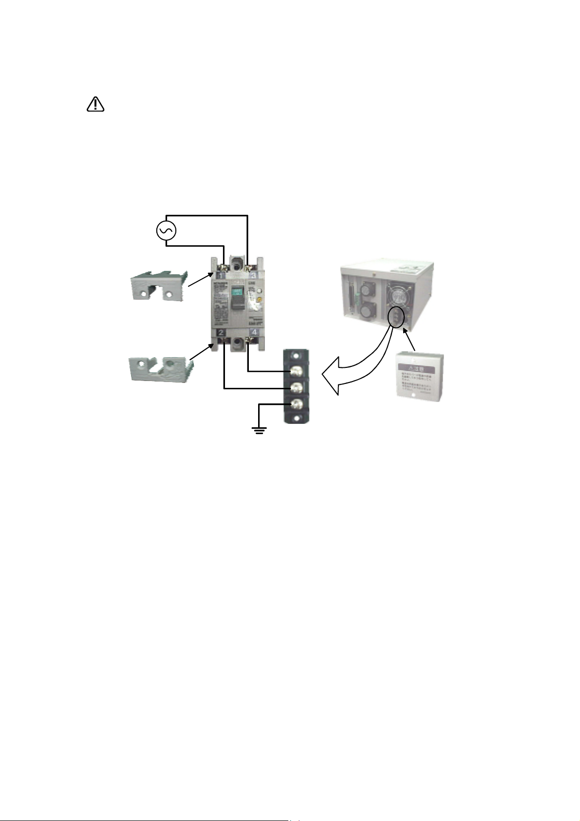
CAUTION
Power supply *RV-1A/2AJ series and RP-1AH/3AH/5AH series: Single phase 90-132VAC, 180-253VAC.
Provide an earth leakage breaker that packed together on the primary power
supply of the controller as protection against electric leakage. Confirm the set
ting connector of the input power supply voltage of the controller, if the type
which more than one power supply voltage can be used. Then connect the
power supply.
Failure to do so could lead to electric shock accidents.
*Except the above: Single phase 180-253VAC.
Cover
Cover
Earth leakage
breaker
(NV)
Terminal
-
Rear side of controller
Protective earth
terminal
(PE)
Terminal cover
Page 5

■ Revision history
Date of print Specifications No. Details of revisions
2000-02-08 BFP-A8050Z First print
2000-04-05 BFP-A8050 Formal style
2000-06-09 BFP-A8050-A The power supply voltage of CR1 controller was corrected
2001-03-12 BFP-A8050-B Error in writing correction.
2002-01-23 BFP-A8050-C LNG, RLNG and MESNGLSW parameters were added.
Error in writing correction.
2002-04-01 BFP-A8050-D CR1-MB (controller protction box) was added.
2002-06-03 BFP-A8050-E RV-1AC-SB, RV-2AJC-SB was added.
2002-07-05 BFP-A8050-F The description of input/output circuit terminal was corrected.
Error in writing correction.
Error in writing correction.
Error in writing correction.
Page 6

■ Introduction
The "RV-1A" and "RV-2AJ" are compact industrial robots developed with Mitsubishi's advanced technology.
These robots respond to users needs for compact and flexible production facilities generated due to the recent
diffusion of compact and highly accuracy products such as personal computer related devices, information termi
nal devices and compact electronic devices for mounting on vehicles, and due to shorter product life cycles.
However, to comply with the target application, a work system having a well-balanced robot arm, peripheral
devices or robot and hand section must be structured.
When creating these standard specifications, we have edited them so that the Mitsubishi robot's characteristics
and specifications can be easily understood by users considering the implementation of robots. However, if there
are any unclear points, please contact your nearest Mitsubishi branch or dealer.
Mitsubishi hopes that you will consider these standard specifications and use our robots.
In this manual, the specifications regarding the robot arm are given in Page 5, "2 Robot arm" and following, and the
specifications regarding the controller are given in Page 38, "3 Controller" and following. Refer to the correspond
ing sections for details on the specifications, options and maintenance parts, etc.
Note:
・ No part of this manual may be reproduced by any means or in any form, without prior consent from Mitsubishi.
・ The contents of this manual are subject to change without notice.
・ The specifications values are based on Mitsubishi standard testing methods.
・ The information contained in this document has been written to be accurate as much as possible. Please inter
pret that items not described in this document "cannot be performed.".
Please contact your nearest dealer if you find any doubtful, wrong or skipped point.
-
-
-
Page 7

Contents
1 General configuration .................................................................................................................................................................... 1-1
1.1 Structural equipment ............................................................................................................................................................. 1-1
1.1.1 Standard structural equipment .................................................................................................................................. 1-1
1.1.2 Shipping special specifications ................................................................................................................................... 1-1
1.1.3 Options ................................................................................................................................................................................. 1-1
1.1.4 Maintenance parts ........................................................................................................................................................... 1-1
1.2 Contents of the structural equipment ............................................................................................................................ 1-2
1.2.1 Robot arm ........................................................................................................................................................................... 1-2
1.3 Controller .................................................................................................................................................................................... 1-3
1.4 Contents of the Option equipment and special specification .............................................................................. 1-4
2 Robot arm ........................................................................................................................................................................................... 2-5
2.1 Standard specifications ........................................................................................................................................................ 2-5
2.2 Definition of specifications .................................................................................................................................................. 2-6
2.2.1 Pose repeatability and distance accuracy ............................................................................................................ 2-6
2.2.2 Rated load (mass capacity) ......................................................................................................................................... 2-7
2.2.3 Protection specifications and working environment ......................................................................................... 2-8
(1) Types of protection specifications ...................................................................................................................... 2-8
2.2.4 Clean specifications ........................................................................................................................................................ 2-9
(1) Types of clean specifications ................................................................................................................................. 2-9
2.3 Names of each part of the robot .................................................................................................................................... 2-10
2.4 Outside dimensions ・ Operating range diagram ........................................................................................................ 2-11
(1) RV-1A/1AC-SB ........................................................................................................................................................ 2-11
(2) RV-2AJ/2AJC-SB ................................................................................................................................................... 2-12
(3) Mechanical interface and Installation surface of RV-1A/2AJ, RV-1AC-SB/2AJC-SB .......... 2-13
2.5 Tooling ........................................................................................................................................................................................ 2-14
2.5.1 Wiring and piping for hand .......................................................................................................................................... 2-14
(1) RV-1A/2AJ (General environment) .................................................................................................................. 2-14
(2) RV-1AC-SB/2AJC-SB (Clean specification) .............................................................................................. 2-15
2.5.2 Internal air piping ............................................................................................................................................................ 2-16
2.5.3 Internal wiring for the pneumatic hand output cable ...................................................................................... 2-16
2.5.4 Internal wiring for the hand check input cable .................................................................................................. 2-16
2.5.5 Wiring and piping system diagram for hand ......................................................................................................... 2-17
(1) RV-1A/2AJ (General environment) .................................................................................................................. 2-17
(2) RV-1AC-SB/2AJC-SB (Clean specification) .............................................................................................. 2-19
2.5.6 Electrical specifications of hand input/output .................................................................................................. 2-21
2.5.7 Air supply circuit example for the hand ............................................................................................................... 2-22
2.6 Shipping special specifications, options, and maintenance parts ...................................................................... 2-23
2.6.1 Shipping special specifications ................................................................................................................................. 2-23
(1) Machine cable extension ........................................................................................................................................ 2-24
2.7 Options ....................................................................................................................................................................................... 2-26
(1) Motorized hand set ................................................................................................................................................... 2-27
(2) Pneumatic hand set .................................................................................................................................................. 2-29
(3) Solenoid valve set ..................................................................................................................................................... 2-31
(4) Hand input cable ........................................................................................................................................................ 2-33
(5) Hand output cable ..................................................................................................................................................... 2-34
(6) Hand curl tube ............................................................................................................................................................ 2-35
(7) Hand adapter ............................................................................................................................................................... 2-36
2.8 Maintenance parts ................................................................................................................................................................. 2-37
Page
3 Controller .......................................................................................................................................................................................... 3-38
3.1 Standard specifications ...................................................................................................................................................... 3-38
3.1.1 Standard specifications ............................................................................................................................................... 3-38
3.1.2 Protection specifications and operating supply ................................................................................................ 3-39
3.2 Names of each part .............................................................................................................................................................. 3-40
3.3 Outside dimensions/Installation dimensions .............................................................................................................. 3-42
i
Page 8

3.3.1 Outside dimensions ...................................................................................................................................................... 3-42
3.3.2 Installation dimensions ................................................................................................................................................ 3-43
3.4 External input/output ......................................................................................................................................................... 3-44
3.4.1 Types .................................................................................................................................................................................. 3-44
3.4.2 Explanation ....................................................................................................................................................................... 3-44
3.5 Dedicated input/output ...................................................................................................................................................... 3-45
3.6 Emergency stop input/output ......................................................................................................................................... 3-47
3.6.1 Connection of the external emergency stop ..................................................................................................... 3-47
3.6.2 Door switch function ................................................................................................................................................... 3-48
3.7 Parallel input/output unit .................................................................................................................................................. 3-49
3.8 Options ...................................................................................................................................................................................... 3-53
(1) Teaching pendant (T/B) ........................................................................................................................................ 3-54
(2) Pneumatic hand interface ..................................................................................................................................... 3-57
(3) Controller protection box ...................................................................................................................................... 3-59
(4) Expansion option box .............................................................................................................................................. 3-62
(5) Parallel I/O unit ......................................................................................................................................................... 3-64
(6) External I/O cable .................................................................................................................................................... 3-72
(7) Personal computer cable ....................................................................................................................................... 3-74
(8) Personal computer support software/Personal computer support software mini ....................... 3-76
3.9 Maintenance parts ................................................................................................................................................................ 3-78
4 Software ........................................................................................................................................................................................... 4-79
4.1 List of commands ................................................................................................................................................................. 4-79
(1) The procedure of robot language selection ................................................................................................... 4-79
(2) MELFA-BASIC Ⅳ commands ............................................................................................................................. 4-80
(3) MOVEMASTER commands ................................................................................................................................... 4-82
4.2 List of parameters ................................................................................................................................................................ 4-85
(1) List of parameters .................................................................................................................................................... 4-85
(2) Change the display language / 表示言語の切り 替え .............................................................................. 4-87
Page
5 Safety ................................................................................................................................................................................................ 5-88
5.1 Safety ........................................................................................................................................................................................ 5-88
5.1.1 Self-diagnosis stop functions .................................................................................................................................. 5-88
5.1.2 External input/output signals that can be used for safety protection measures ............................. 5-88
5.1.3 Precautions for using robot ...................................................................................................................................... 5-89
5.1.4 Safety measures for automatic operation .......................................................................................................... 5-89
5.1.5 Safety measures for teaching .................................................................................................................................. 5-89
5.1.6 Safety measures for maintenance and inspections, etc. ............................................................................. 5-89
5.1.7 Examples of safety measures .................................................................................................................................. 5-90
5.2 Working environment ........................................................................................................................................................... 5-91
5.3 Precautions for handling .................................................................................................................................................... 5-91
6Appendix ..............................................................................................................................................................................Appendix-92
Appendix 1 : Specifications discussion material ........................................................................................... Appendix-92
ii
Page 9

1General configuration
1 General configuration
1.1 Structural equipment
Structural equipment consists of the following types.
1.1.1 Standard structural equipment
The following items are enclosed as a standard.
(1) Robot arm
(2) Controller
(3) Machine cable
(4) Robot arm installation bolts
(5) Instruction manual, Safety manual
(6) Guarantee card
1.1.2 Shipping special specifications
Part of the standard structural equipment is changed at the time of factory shipment. Consequently, kindly con
firm the delivery date.
To make changes to the specifications after shipment, service work must be performed at the work site or the
robot must be returned for service.
1.1.3 Options
Installation is possible after shipment. Customer needs to perform the installation work.
-
1.1.4 Maintenance parts
Consumable parts and spare parts for maintenance use.
For items not listed, contact the dealer where you made your purchase.
Structural equipment
1-1
Page 10
1General configuration
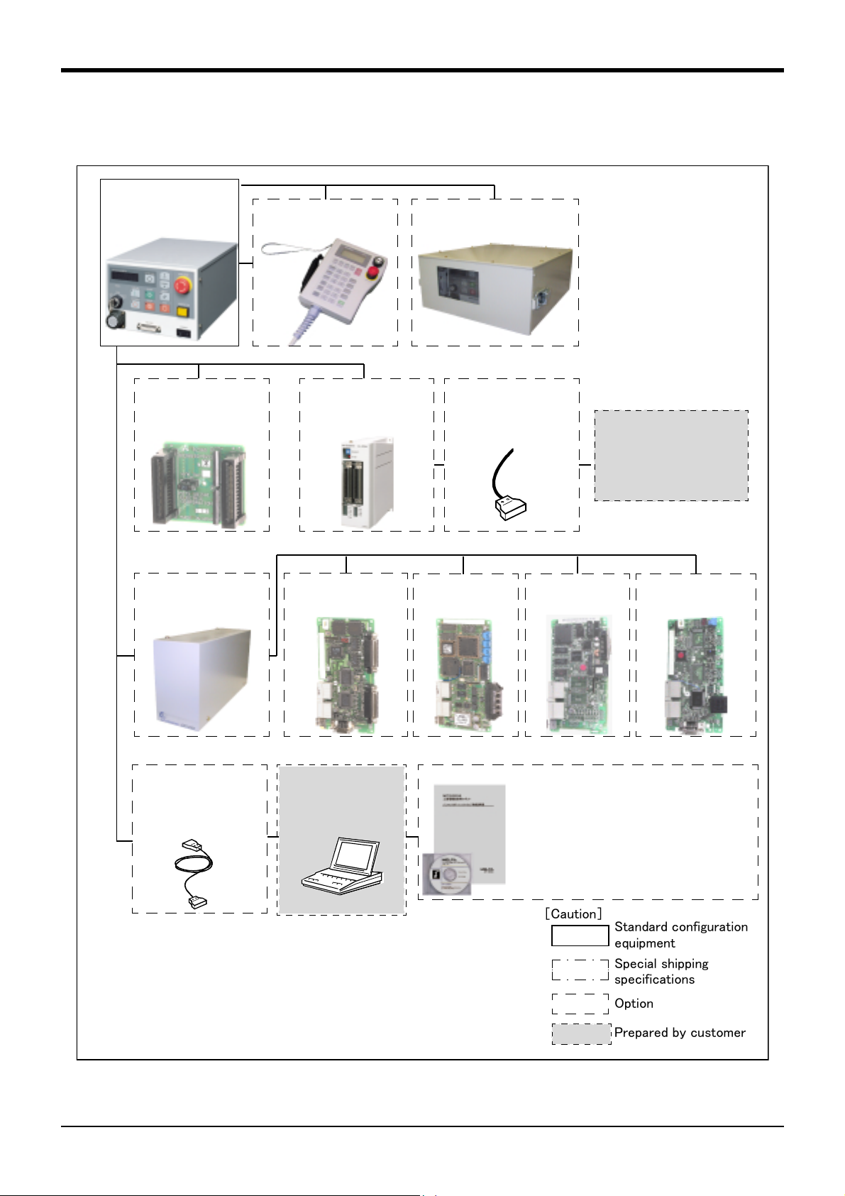
1.2 Contents of the structural equipment
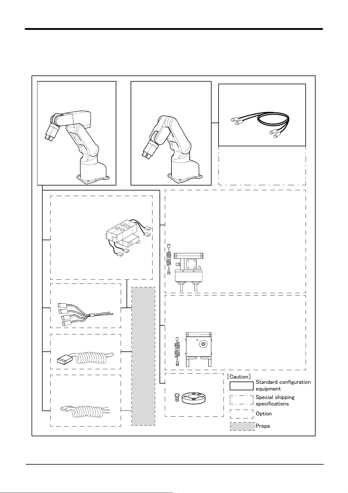
1.2.1 Robot arm
The list of structural equipment is shown in Fig. 1-1.
Vertical six-axis
RV-1A:
RV-1AC-SB:
General environment
Clean specification
Solenoid valve set
<sink type>
・1 set: 1E-VD01
・ 2 set: 1E-VD02
<source type>
・1 set: 1E-VD01E
・ 2 set: 1E-VD02E
Vertical five-axis
multiple-jointed type
RV-2AJ:
RV-2AJC-SB:
or
Machine cable fixed type 5m
General environment
Clean specification
・1A-5CBL-1
Machine cable
・ Fixed type:1A- □□ CBL-1
・ Flexed type:1A- □□ LCBL-1
Note) □□ refer the length.
Refer to section "1.4" for datails.
Pneumatic hand set
:
4A-HP01(sink type)/4A-HP01E (source type)
The set consists of the following parts.
Pneumatic hand
・
Solenoid valve set (1 pc.)
・
・ Curl cable :1A-GHCD/1A-GHCD
Hand curl tube
・
Pneumatic hand I/F
・
・ Hand adapter :1A-HA01/1A-HA01
:1A-HP01/1A-HP01E
:1E-VD01/1E-VD01E
:1A-ST0402C/1A-ST0402C
: 2A-RZ365/2A-RZ375
Note) Not
clean specification
Hand output cable
・1E-GR35S
Hand input cable
・1A-HC20
Hand curl tube
・
1 set, 2pc
・
2 set, 4pc
. :1E-ST0402C
. :1E-ST0404C
With installation bolts.
Pneumatic hand customer-manufactured parts
With installation bolts.
Note) Not
Motorized hand set : 4A-HM01
・ Motorized hand :1A-HM01
・ Curl cable :1A-GHCD
・ Motorized hand
・ Hand adapter :1A-HA01
I/F
clean specification
: 2A-RZ364
With installation bolts.
Note) Not
Hand adapter
:1A-HA01
clean specification
[Caution]
Standard configuration
equipment
Special shipping
specifications
With installation bolts.
Option
Prepared by customer
Fig.1-1:Structural equipment (Robot arm)
1-2
Contents of the structural equipment
Page 11
1.3 Controller
ETHERNET I/F
・ 2A-HR533E
The devices shown below can be installed on the controller.
Controller
・ CR1-571
Teaching pendant(T/B)
・ R28TB
Controller protection box
・ CR1-MB
1General configuration
Pneumatic I/F
・ 2A-RZ365 (Sink)
・ 2A-RZ375 (Source)
Expansion option box
・ CR1-EB3
Personal computer
cable
・ RS-MAXY-CBL
・ RS-AT-RCBL
Parallel I/O unit
・ 2A-RZ361 (Sink)
・ 2A-RZ371 (Source)
Extended serial I/F
・ 2A-RZ581E
Personal computer
Prepared
by customer
External I/O cable
・ 2A-CBL05(5m)
・ 2A-CBL15(15m)
CC-LINK I/F
・ 2A-HR575E
Personal computer support software
(MS-Windows95/98/NT4.0)
・ 3A-01C-WINE(CD-ROM)
Personal computer support software mini
(MS-Windows95/98/NT4.0)
・ 3A-02C-WINE(CD-ROM)
PLC(Programmable
Logic Controller)
External device
Prepared by customer
Additional axis I/F
・ 2A-RZ541E
Fig.1-2 : Structural equipment(Controller)
[Caution]
Standard configuration
equipment
Special shipping
specifications
Option
Prepared by customer
Controller
1-3
Page 12

1General configuration
1.4 Contents of the Option equipment and special specification
A list of all Optional equipments and special specifications are shown below.
Table 1-1:The list of Option equipment and special specification
Item Type Specifications
Extended machine cables 1A-10CBL-1
1A-15CBL-1□15m
1A-05LCBL-1
1A-10LCBL-1□10m
1A-15LCBL-1□15m
Pneumatic hand set 4A-HP01
4A-HP01E
Motorized hand set 4A-HM01
Solenoid valve set 1E-VD011 set(Sink type) ○ A solenoid valve set for the pneumatic hand.
1E-VD02 2 set(Sink type) ○
1E-VD01E 1 set(Source type) ○
1E-VD02E 2 set(Source type) ○
Hand output cable 1E-GR35S Length 350mm with robot side con
Hand input cable 1A-HC20 Length 200mm with robot side con
Hand curl tube 1E-ST0402C For solenoid valve 1set.:Φ4x2 ○
1E-ST0404C For solenoid valve 2set.:Φ4x4 ○
Hand adapter 1A-HA01○
Teaching pendant R28TB Cable length 7m ○ With 3-position deadman switch/ IP 65
Pneumatic hand interface
Parallel I/O interface
External I/O cable 2A-CBL05 5m ○ Use to connect the external peripheral device to
Personal computer cable
Personal computer
Support software
Personal computer
Support software mini
Expansion option box CR1-EB3 Up to three option cards can be
Extended serial interface
CC-Link interface 2A-HR575E Local station (The local station
ETHERNET interface 2A-HR533E ETHERNET x 1○CR-EB3 is need.
Additional axis interface 2A-RZ541ESSC x 1
Controller protection box CR1-MB IP54 □
2A-RZ365
2A-RZ375
2A-RZ361
2A-RZ371
2A-CBL15 15m ○
RS-MAXY-CBL
RS-AT-RCBL ○
3A-01C-WINE CD-ROM ○
3A-02C-WINE CD-ROM ○
2A-RZ581E
For fixing
(Two sets for power and signal)
For flexed
(Two sets for power and signal)
Pneumatic hand, Solenoid valve set
(1 pc.), Curl tube(1 pc.), Pneumatic
hand I/F, Hand adapter, Installation
bolts
Motorized hand, Hand curl cable,
Motorized hand I/F, Hand adapter,
Installation bolts
nector. One terminal is not treated.
nector. One terminal is not treated.
DO: 8 point (Sink type)
DO: 8 point (Source type)
DO: 32 point (Sink type)/
DI : 32 point (Sink type)
DO: 32 point (Source type)/
DI : 32 point (Source type)
RS-232C cable 3m for PC-AT com
patible model
mounted
RS-232C x 1
RS-232C or RS-422 x 1
alone is supported.)
Up to 8 axises can be added
*1)
*1)
Note1) In the classification column, ○ refers to an option,and □ to a Sipping special specifications.
Note2) Use this option to protect the controller from the oil mist when the controller will be installed in the environ
ment such as the oil mist.
Classific
ation
□10m
□ 5m
The pneumatic hand and required parts are pre
○
pared in a set.(sink type)
The pneumatic hand and required parts are pre
○
pared in a set.(source type)
The motorized hand and required parts are pre
○
pared in a set.
-
-
-
The cable is connected to the hand output con
○
nector by the customer.
The cable is connected to the sensor by the cus
○
tomer.
Curl type air tube
For RV-M1 hand installation flange conversion.
It is necessary when the hand output signal of the
○
robot arm is used. (Integrated in the controller.)
*1)In RV-1A/2AJ type, even four points are
○
effective.
The unit for expansion the external input/output.
○
Electrical isolated Type
(100mA/Point)
○
the parallel input/output unit
Use RS-AT-RCBL for the connection from the
○
expansion option box.
MS-Windows95/98/NT4.0
(With the simulation function)
MS-Windows95/98/NT4.0
(Without the simulation function)
○ Install on the side of the controller
CR-EB3 is need.
○
for MELSEC PLC with CC-Link connection. CR-
○
EB3 is need.
MR-J2 servoAmplifer Unit connection. CR-EB3 is
○
need.
The controller protection box is used to protect
the controller from an oil mist or other operating
environment.
Descripsion
Note2)
-
-
-
-
-
-
1-4
Contents of the Option equipment and special specification
Page 13

2 Robot arm
2.1 Standard specifications
2.1.1 Standard specifications
Table 2-1:Tab Standard specifications of robot
Item Unit Specifications
Type RV-1ARV-1AC-SB RV-2AJ RV-2AJC-SB
Degree of freedom 6 5
Installation posture On floor, hanging On floor On floor, hanging On floor
Structure Vertical, multiple-joint type
Drive system ACservo motor (J1 toJ3:50W with brake, J4,J6:15W no brake, J5:15Wwith brake)
Position detection method Absolute encoder
Shoulder shift
Upper arm 250
Arm length
Operating
range
Speed of
motion
Maximum resultant velocity mm/s Approx. 2200 Approx. 2100
Load
Pose repeatability
Ambient temperature ℃ 0 to 40
Mass kg Approx. 19 Approx. 17
Allowable
moment load
Allowable
inertia
Arm reachable radius
(front p-axis center point)
Tool wiring
Tool pneumatic pipes
Supply pressure MPa 0.5 ±10%
Protection specification
Degree of cleanliness
Paint color Light gray (Equivalent to Munsell: 7.65Y7.6/0.73)
Fore arm 160
Elbow shift 90 0
Wrist length 72
J1
J2 180(-60 to +120)
J3 95(+60 to +155) 230(-110 to +120)
J4 320(-160 to +160) -
J5 180(-90 to +90)
J6 400(-200 to +200)
J1
J2 90
J3 135
J4 180 -
J5 180
J6 210
Maximum
Rating 11.5
J4
J5 1.44 2.16
J6 0.73 1.10
J4
J5 2.16x10
J6 5.62x10
Note3)
Note1)
Note2)
Note4)
Note5)
mm
Degree
Degree/
s
kg
mm ± 0.02
N ・ m
2
kg ・m
mm 418410
Φ4x4 (Base to hand
Four input signals (Hand section), Four output signals (Base section),
section)
IP30 - IP30 -
-100(0.3μm) -100(0.3μm)
1.5 2
1.44 -
-2
2.16x10
-2
-3
Motorized hand output (Hand section)
Φ4x3 (Base to hand
section)
Note1)The maximum load capacity is the mass with the flange posture facing downword at the ±10 degree
limit.
Note2)The pose repeatability details are given in Page 6, "2.2.1 Pose repeatability and distance accuracy"
Note3)When using the 4-point hand output, the pneumatic hand interface (option) is required.
Note4)The protection specification details are given in Page 8, "2.2.3 Protection specifications and working
environment" .
Note5)The down flow (0.3m/s or more) in the clean room and the internal suction by using attached vacuum
generating valve are necessary conditions for the cleanliness.
0
300(-150 to +150)
180
Φ4x4 (Base to hand
section)
-
-2
3.24x10
-3
8.43x10
Φ4x3 (Base to hand
section)
2Robot arm
Standard specifications
2-5
Page 14
2 Robot arm
2.2 Definition of specifications
The accuracy of pose repeatability mentioned in catalogs and in the specification manual is defined as follows.
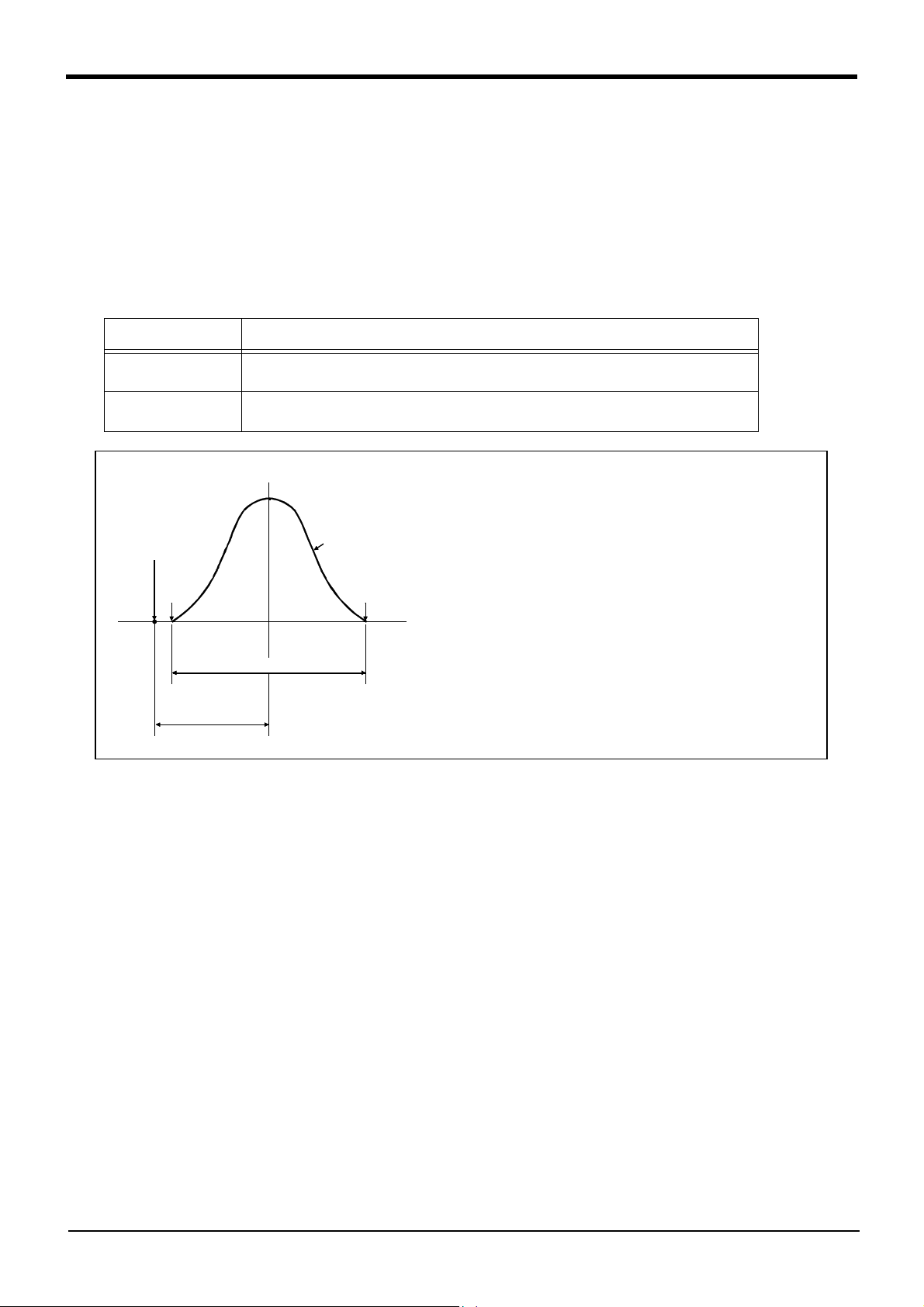
2.2.1 Pose repeatability and distance accuracy
This robot, the pose repeatability and distance accuracy are defined and calculated in Table 2-2.
(1) The pose accuracy in terms of coordinates (XYZ) for the standard point which is obtained repeatedly under
the same conditions and motions when the robot is on an operating course.
(2) The standard point is the intersection between the J6 axis and the flange surface for tooling installation.
Table 2-2 : Specified accuracy
Item Specified conditionds
Pose repeatability The value equal to the average of the maximum value and the minimum value of the group of
attained poses, with (+) or (-) added.
Distance accuracy The distance from the teaching point to the point that is equal to the average of the maximum
value and the minimum value of the group of attained poses.
Group of attained poses
Programmed pose
Min.
(X, Y, Z)
Max.
Measuring conditions
Load ................................................................A load equal to the rated
load at the mass capacity
Double of pose repeatability
Distance
accuracy
The number of repitition and speed ..100 times at 100% speed
Measuring instrument ..............................Non-contact displace
reference point
-
ment meter
Fig.2-1:Specified accuracy
[Caution] The pose accuracy given in the specifications is the accuracy measured under the same conditions. It
does not include the effect of the robot working environment or conditions. Thus, even when used on
the same path, the repeatability according to the presence of a workpiece, or the repeatability when the
temperature changes will cause arm slack or expansion, so the accuracy will drop slightly. This also
applies to when the teaching speed and actual speed are different or when the coordinates set with val
ues.
-
2-6
Definition of specifications
Page 15
2 Robot arm
2.2.2 Rated load (mass capacity)
The robot's mass capacity is expressed solely in terms of mass, but even for tools and works of similar mass,
eccentric loads will have some restrictions. When designing the tooling or when selecting a robot, consider the fol
lowing issues.
(1) The tooling should have the value less or equal than the smaller of the tolerable inertia and the tolerable
moment found in Page 5, "Table 2-1: Tab Standard specifications of robot".
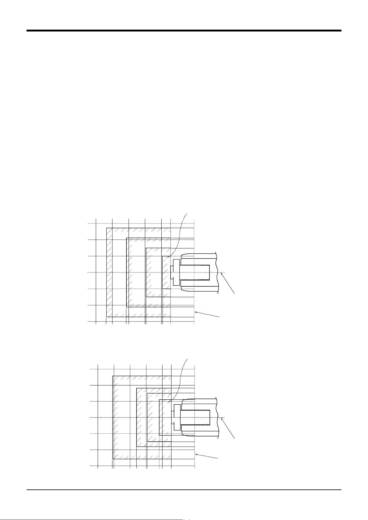
(2) Fig. 2-2 and Fig. 2-3shows the distribution dimensions for the center of gravity in the case where the vol
ume of the load is relatively small. Use this figure as a reference when designing the tooling.
(3) When the load is not mass, but force, you should design the tooling so that it does not exceed the value for
allowable moment described in Page 5, "Table 2-1: Tab Standard specifications of robot".
[Caution] The mass capacity is greatly influenced by the operating speed of the robot and the motion posture.
Even if you are within the allowable range mentioned previously, an overload or generate an overcurrnt
alarm could occur. In such cases, it will be necessary to change the time setting for acceleration/decel
eration, the operating speed, and the motion posture.
[Caution] The overhang amount of the load for the specified moment and inertia in this section is the dynamic limit
value determined by the motor driving each axis and by the capacity of the reduction gears. Conse
quently, accuracy cannot be guaranteed for the entire tooling area. Since accuracy is based on the cen
ter point of the mechanical interface surface, position accuracy can diminish as you go away from the
flange surface, or vibration can result, with tooling that is not rigid or that is long.
-
-
-
-
-
Maximum load capacity
Maximum load capacity
Maximum load capacity Maximum load capacity
with the flange posture facing downword
with the flange posture facing downword
with the flange posture facing downwordwith the flange posture facing downword
150
150
150150
136
136
136136
0.3kg
0.3kg
300
300
300300
0.3kg0.3kg
200
200
200200
250
250
250250
268
268 207
268268
207 147
207207
0.5kg
0.5kg
0.5kg0.5kg
1.0kg
1.0kg
1.0kg1.0kg
150
150150
147 97
147147
100
100
100100
1.5
1.5
1.51.5
kg
kg
kgkg
72
72
7272
97
9797
106
106
106106
100
100
100100
75
75
7575
50
50
5050
0000150
50
50
5050
Rotation center for J6 axis
Rotation center for J6 axis
75
75
7575
100
100
100100
106
106
106106
136
136
136136
150
150
150150
Rotation center for J6 axis Rotation center for J6 axis
Rotation center for J5 axis
Rotation center for J5 axis
Rotation center for J5 axis Rotation center for J5 axis
Fig.2-2 : Position of center of gravity for loads (for loads with comparatively small volume) : RV-1A/1AC-SB
Maximum load capacity
Maximum load capacity
Maximum load capacity Maximum load capacity
with the flange posture facing downword
with the flange posture facing downword
with the flange posture facing downwordwith the flange posture facing downword
150
150
150150
129
129
129129
0.5kg
0.5kg
0.5kg0.5kg
1.0kg
1.0kg
1.0kg1.0kg
1.5kg
1.5kg
1.5kg1.5kg
2kg
2kg
2kg2kg
100
100
100100
91
91
9191
75
75
7575
56
56
5656
72
72
110
110110
7272
0000
56
56
5656
75
75
7575
91
91
9191
100
100
100100
129
129
129129
150
150
150150
Rotation center for J6 axis
Rotation center for J6 axis
Rotation center for J6 axis Rotation center for J6 axis
Rotation center for J5 axis
Rotation center for J5 axis
Rotation center for J5 axis Rotation center for J5 axis
300
300
300300
250
250 200
200 150
250250
200200
254
254 180
254254
150 100
150150
180 147
147 110
180180
147147
100
100100
Fig.2-3 : Position of center of gravity for loads (for loads with comparatively small volume) : RV-2AJ/2AJC-SB
Definition of specifications
2-7
Page 16

2 Robot arm
2.2.3 Protection specifications and working environment (1) Types of protection specifications
The robot arm has protection specifications that comply with the IEC Standards. The protection specifications
and applicable fields are shown in Table 2-3.
Table 2-3 : Protection specifications and applicable fields
Protection
specifications
General-purpose envi
ronment specifications
CAUTION
IEC Standards
value
-
IP30 General assembly
Slightly dusty environment
Use the controller protection box (CR1-MB) optional to protect the controller from
Applicable field Remarks
the environment when the controller will be used in the environment such as the oil
mist shown in the Table 2-3. Refer to the section Page 59, "(3) Controller protection
box" for details on the controller protection box.
【Information】
・ The IEC IP30
IP30 refers to a protective structure with which the tip of a solid object, such as a tool or wire, having a
diameter or thickness exceeding 2.5mm cannot enter. No particular protection is provided against the entry of
water.
The warranty is invalid for any faults that occur when the robot is used under the following conditions.
1) In surroundings that generate inflammable gases or corrosive gasses.
2) In surroundings where water, oil, and chips fall directly on the robot.
3) Mist atmosphere exceeding the specification.
2-8
Definition of specifications
Page 17

2.2.4 Clean specifications (1) Types of clean specifications
The clean specifications of robot arm shown in Table 2-4.
Please confirm the delivery date, because both are special specifications.
Table 2-4 : Clean specifications
2 Robot arm
Clean
specifications
Type SB RV-1AC-SB
Type
RV-2AJC-SB
Degree of
cleanliness
100(0.3μm) Internal suction with vaccum generating valve. A vacuum generating
Internal suction Remarks
valve (refer to Table 2-
5) is enclosed.
Table 2-5 : Specifications of vacuum generation valve
Type Maker Air pressure
MEDT 10 Koganei 0.2 to 0.6 MPa
■ Precautions for use
1) When using a device that moves or rotates the robot arm, the down flow may not be secured because of the
air flow. In this case, the degree of cleanliness cannot be ensured.
2) In the case of clean specification robot, the base side hoses are four and fore arm side hoses are three.
Prepare the hose of Φ4 x 2.5 and connect this joint to the appended vacuum generating valve or the vac
uum pump prepared by the customer.
* If the appended vacuum generating valve is used, connect the rear joint of the robot to the joint on the
"VACUUM" side of the vacuum generating valve. Moreover, in order to prevent the exhaust of the vacuum
generating valve from impairing the cleanness, install the vacuum generating valve on the downstream side
of the down flow or attach the filter to the exhaust section as possible.
Recommended filter: Exhaust filter EF300-02, Koganei Corporation
* If any vacuum pump is prepared by the customer, assure on the vacuum side flow rate 50 liters/min.(ANR)
or more .
-
Definition of specifications
2-9
Page 18

2 Robot arm
2.3 Names of each part of the robot
Fore arm
J5-axis
-
+
+
J6-axis
Mechanical interface
(Hand installation flange surface)
-
+
-
Shoulder
Note)
J4-axis
-
-
J1-axis
Elbow block
+
Upper arm
+
-
J3-axis
+
J2-axis
Base
Fig.2-4 : Names of each part of the robot
2-10
Names of each part of the robot
Note)J4-axis dosen't exist for 5-axis type.
Page 19
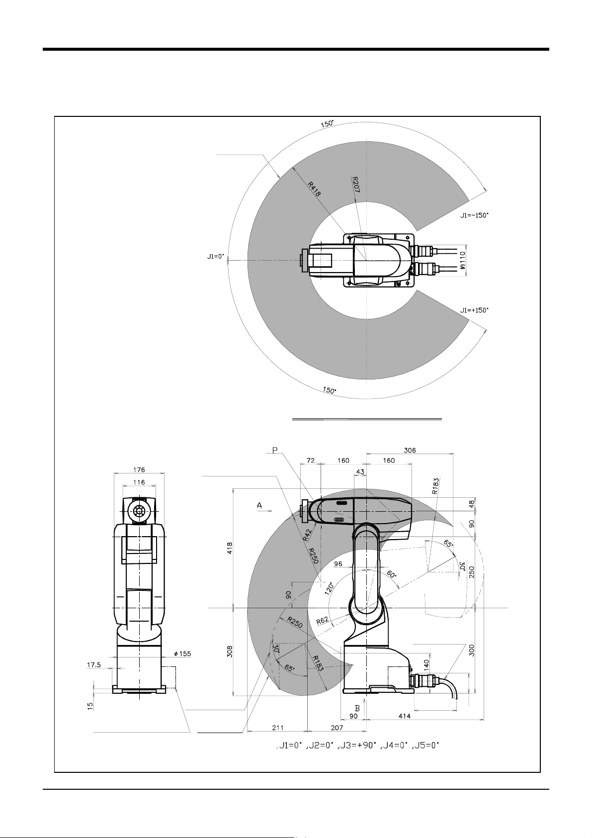
2.4 Outside dimensions ・ Operating range diagram
(1) RV-1A/1AC-SB
P point path
2 Robot arm
Operating range at section of X-X
Flange downward
limit line(dotted line)
XX
Machine cable
(Connect to
the controller)
(Front)
Flange downward
Solenoid valve (optional)
installation position
singular point path
P point path
150 or more
(Back projects)
Note 1) Refer to Fig. 2-7 for the hand installation flange section and installation base section dimensions.
Approx. 70
pose
Fig.2-5 : Outside dimensions for RV-1A/1AC-SB
Outside dimensions ・ Operating range diagram
2-11
Page 20

2 Robot arm
(2) RV-2AJ/2AJC-SB
P point path
(Front)
Solenoid valve (optional)
installation position
Operating range at section of X-X
Flange downward
limit line(dotted line)
P
XX
P point path
Machine cable
(Connect to
the controller)
150 or more
Back side limitations
(Two dotted line)
Approx. 70
Note 1) Refer to Fig. 2-7 for the hand installation flange section and installation base section dimensions.
Fig.2-6 : Outside dimensions for RV-2AJ/2AJC-SB
2-12
Outside dimensions ・ Operating range diagram
pose
Page 21
.
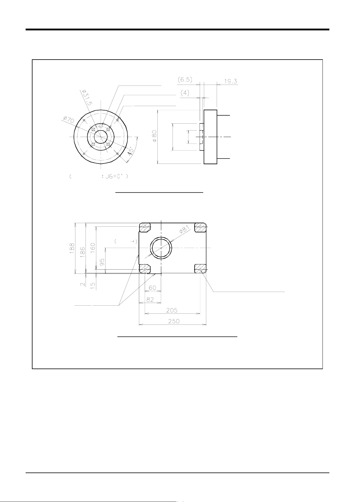
(3) Mechanical interface and Installation surface of RV-1A/2AJ, RV-1AC-SB/2AJC-SB
φ5H7, depth 8
reference hole
(
4-M5 screw,depth 8
4-M3 screw, depth 6
View from A
)
φ20H7,
φ40H8,
depth 4
depth 6.5
Detail of Mechanical interface
(ISO9409-1 )
2 Robot arm
Front
*
6.3a
Installation
reference surface
6.3a
4-φ9 hole
(Installation bolts for M8×35)
View from B : Installation dimension details
・The contact section shown with shading on the robot installation surface must be finished to 6.3a.
・The section marked with * must be contacted against the installation surface to ensure the robot rigidity
Fig.2-7 : Mechanical interface and Installation surface of RV-1A/2AJ, RV-1AC-SB/2AJC-SB
Outside dimensions ・ Operating range diagram
2-13
Page 22
2 Robot arm
2.5 Tooling
2.5.1 Wiring and piping for hand
Shows the wiring and piping configuration for a standard-equipped hand.
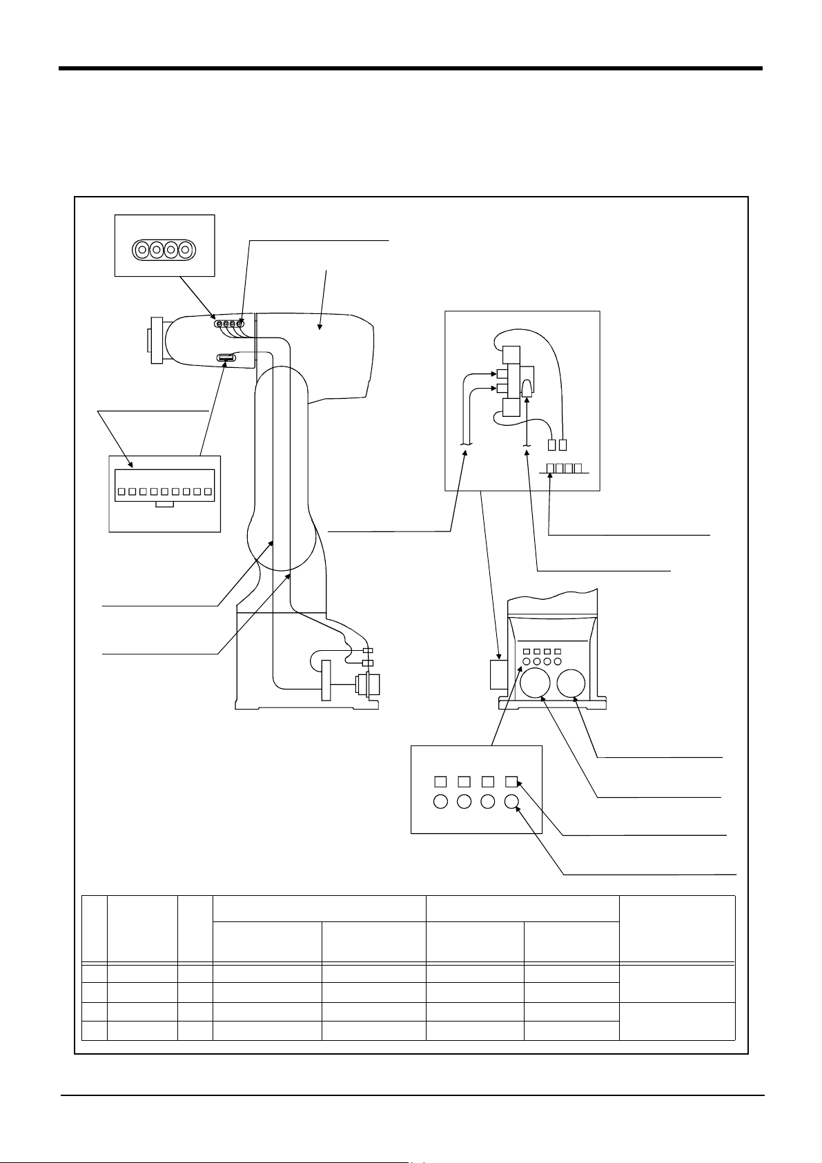
(1) RV-1A/2AJ (General environment)
Number of coupling for hand
AIR OUT
1 2 3 4
(1) Hand input signal or
motorized hand
connectors
(3) 1 to 4 : Secondary piping
couplings (φ4)
Note) This parts dosn't exist for 5-axis type
Note)
Solenoid valve set(optional)
installation section
a)
b)
9 8 7 6 5 4 3 2 1
CON1H
Hand connector pin assignment
Hand input signal and
motorized hand
cables
Secondary piping hoses
(φ4*4)
Note1)When using the hand output signal, it is necessary
to use the optional pneumatic hand interface
(2A-RZ365/2A-RZ375)
Note2)The user must prepare the φ4 and φ6
pneumatic hoses for connecting to the solenoid
valve set.
Secondary piping
pneumatic hoses(φ4)
Note2)
Magnification
GR1 GR2 GR3 GR4
Number of connector
for hand output.
Number of coupling for hand.
1 234
AIR IN
Connector and pneumatic coupling
Robot side(Robot arm side) Counter side (customer-prepared)
No Name Qty.
(1) Connector 1 SMP-09V-BC BHF-001GI-0.8BS SMP-09V-B BYM-001T-0.6 Japan solderless ter
(2) Connector 4 SMP-02V-BC BHF-001GI-0.8BS SMR-02V-B BYM-001T-0.6
(3) Coupling 4 TSH4-M5M ---Koganei
(4) Coupling 4 UKBL4 ---
Connectors,
couplings
Connector pins Connector Connector pins
GR1 to GR4 : Connect to the b)
Hand output connector
Primary piping
pneumatic hoses(φ6*1)
Note2)
CN2 CN1
Machine cable connector
(Power supply)
Machine cable connector
(Signals)
(2)GR1 to GR4:Connect to the b)
Hand output connector
(4) AIR IN 1 to 4:Connect to the a)
Secondary piping air coupling(φ4)
Manufacturer
minal MFG. Co.,LTD
-
Fig.2-8 : Wiring and piping for hand (RV-1A/2AJ)
2-14
Tooling
Page 23
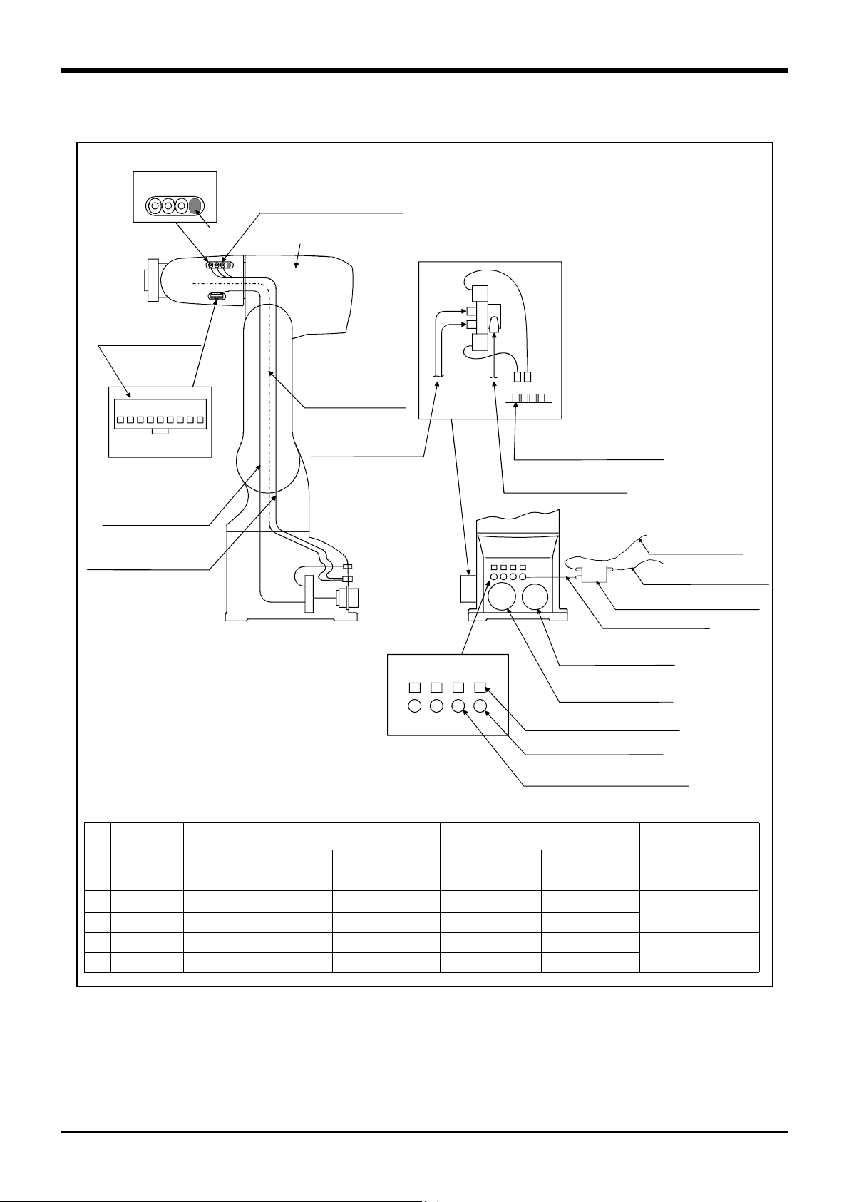
(2) RV-1AC-SB/2AJC-SB (Clean specification)
Number of coupling for hand
AIR OUT
1 2 3 4
(1) Hand input signal or
motorized hand
connectors
Not use
(3) 1 to 3 : Secondary piping
couplings (φ4)
Note) This parts dosn't exist
for 5-axis type
Note3) Solenoid valve set
(optional, not clean secification)
installation section
a)
b)
2 Robot arm
9 8 7 6 5 4 3 2 1
Hand connector pin assignment
(φ4x4: One of those is used
for internal suction)
Note1)When using the hand output signal, it is necessary
to use the optional pneumatic hand interface.
(2A-RZ365/2A-RZ375)
Note2)The user must prepare the φ4 and φ6
pneumatic hoses for connecting to the solenoid
valve set.
Note3)The φ 6 pneumatic hose (for exhaust and
compressed air) and φ 4 pneumatic hose
(for suction) must be prepared by the user.
Note4)The vacuum solenoid valve must be fixed by
the user.
Note5)Suction is possible by connecting the vacuum pump
which is prepared by the user. In this case, select
a flow rate of 50 liters/min. as a guideline.
CON1H
Hand input signal and
motorized hand
cables
(Not use)
Secondary piping hoses
Internal suction (φ4)
Secondary piping
pneumatic hoses(φ4)
Note2)
Magnification
Number of connector
for hand output.
Number of coupling for hand.
GR1 GR2 GR3 GR4
1 234
AIR IN
GR1 to GR4 : Connect to the b)
Hand output connector
Primary piping
pneumatic hoses(φ6*1)
Note2)
CN2 CN1
Machine cable connector
(Power supply)
Machine cable connector
(Signals)
(2)GR1 to GR4:Connect to the b)
Hand output connector
Coupling for internal suction
(4) AIR IN 1 to 4:Connect to the a)
Secondary piping air coupling(φ4)
Vacuum solenoid valve Note4)
For suctionφ4 Note5)
Exhaustφ6 Note3)
Compressed airφ6 Note3)
Connector and pneumatic coupling
Robot side(Robot arm side) Counter side (customer-prepared)
No Name Qty.
(1) Connector 1 SMP-09V-BC BHF-001GI-0.8BS SMP-09V-B BYM-001T-0.6 Japan solderless ter
(2) Connector 4 SMP-02V-BC BHF-001GI-0.8BS SMR-02V-B BYM-001T-0.6
(3) Coupling 3 TSH4-M5M ---Koganei
(4) Coupling 4 UKBL4 ---
Connectors,
couplings
Connector pins Connector Connector pins
Manufacturer
minal MFG. Co.,LTD
-
Fig.2-9 : Wiring and piping for hand (RV-1AC-SB/2AJC-SB)
Tooling
2-15
Page 24

2 Robot arm
2.5.2 Internal air piping
(1) The robot has four φ4 x 2.5 urethane hoses from the pneumatic entrance on the base section to the foure
arm side.They are three in the case of clean specification.
(2) The hose end section has four coupling bridges for a φ4 hose on both the base and forearm side. In the case
of clean specification robot, the base side hoses are four and fore arm side hoses are three.
(3) The robot can have up to two pneumatic valve sets on the side of base (optional).
(4) Refer to Page 31, "Solenoid valve set" for details on the electronic valve set (optional).
2.5.3 Internal wiring for the pneumatic hand output cable
(1) The hand output cable extends from the connector of the base section to the side of the base section.
2
(AWG#24(0.2mm
connector names are GR1 to GR4.
) x 2 : 4 cables) The cable terminals have connector bridges for four hand outputs. The
2.5.4 Internal wiring for the hand check input cable
(1) The hand check input cable is wired to four points on the forearm side from the base.
-
2-16
Tooling
Page 25
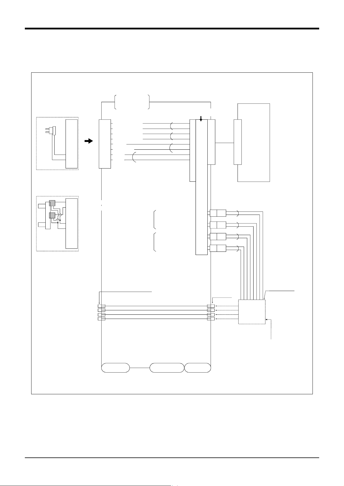
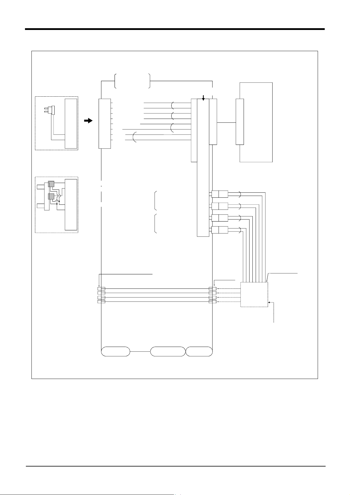
2.5.5 Wiring and piping system diagram for hand
Shows the wiring and piping configuration for a standard-equipped hand.
(1) RV-1A/2AJ (General environment)
<Sink type>
2 Robot arm
During use of
motorized
hand I/F(optional)
During use of
pneumatic
hand I/F(optional)
1
2
3
4
5
6
7
8
<Hand check 1>
1
2
<Hand check 1>
3
4
<+24V>
5
<0V(COM)>
6
7
8
9
1
<Hand check 1>
2
<Hand check 2>
3
<Hand check 3>
4
<Hand check 4>
5
<+24V>
6
<0V(COM)>
7
<DC+>
8
<DC->
99
Note1)
During use of
pneumatic
hand I/F.
White
Black
*1
*1
*1 is dedicated for the motorized
hand.
It is valid when the motorized
hand interface is installed.
General-purpose output
Hand 1
ON/OFF
Hand 2
ON/OFF
General-purpose output
General-purpose output
General-purpose output
White
Black
White
Black
White
Black
General-purpose
input No.
900
901
902
903
900
+24V
901
+24V
902
+24V
903
+24V
GR1
1
2
GR2
1
2
GR3
1
2
GR4
1
2
White
Black
White
Black
White
Black
White
Black
Robot
controller
Solenoid valve
section
Solenoid valve
manifold
Connect to the
primary air supply
(φ6 hose)
AIR OUT1
AIR OUT2
AIR OUT3
AIR OUT4
φ4 quick coupling bridge(1 to 4)
φ4 hose(4 hoses)
Wrist section
Shoulder section
Base section
φ4 quick
coupling
AIR IN1
AIR IN2
AIR IN3
AIR IN4
Solenoid valve
installation
section
(optional)
*Refer to Fig. 2-14 for air supply cir
cuit example.
Fig.2-10 : Wiring and piping system diagram for hand and example the solenoid valve installation(Sink type)
-
Tooling
2-17
Page 26
2 Robot arm
<Source type>
During use of
motorized
hand I/F(optional)
During use of
pneumatic
hand I/F(optional)
1
2
3
4
5
6
7
8
<Hand che ck 1>
1
2
<Hand che ck 1>
3
4
<+24V(COM)>
5
<0V>
6
7
8
9
1
<Hand check 1>
2
<Hand check 2>
3
<Hand check 3>
4
<Hand check 4>
5
<+24V(COM)>
6
<0V>
7
<DC+>
8
<DC->
99
Note1)
During use of
pneumatic
hand I/F.
White
Black
*1
*1
*1 is dedicated for the motorized
hand.
It is valid when the motorized
hand interface is installed.
General-purpose output
Hand 1
ON/OFF
Hand 2
ON/OFF
General-purpose output
General-purpose output
General-purpose output
White
Black
White
Black
White
Black
General-purpose
input No.
900
901
902
903
900
24G
901
24G
902
24G
903
24G
GR1
1
2
GR2
1
2
GR3
1
2
GR4
1
2
White
Black
White
Black
White
Black
White
Black
Robot
controller
Solenoid valve
section
Solenoid valve
manifold
Connect to the
primary air supply
(φ6 hose)
AIR OUT1
AIR OUT2
AIR OUT3
AIR OUT4
φ4 quick coupling bridge(1 to 4)
φ4 hose(4 hoses)
Wrist section
Shoulder section
Base section
φ4 quick
coupling
AIR IN1
AIR IN2
AIR IN3
AIR IN4
Solenoid valve
installation
section
(optional)
*Refer to Fig. 2-14 for air supply cir
cuit example.
Fig.2-11 : Wiring and piping system diagram for hand and example the solenoid valve installation(Source type)
-
2-18
Tooling
Page 27
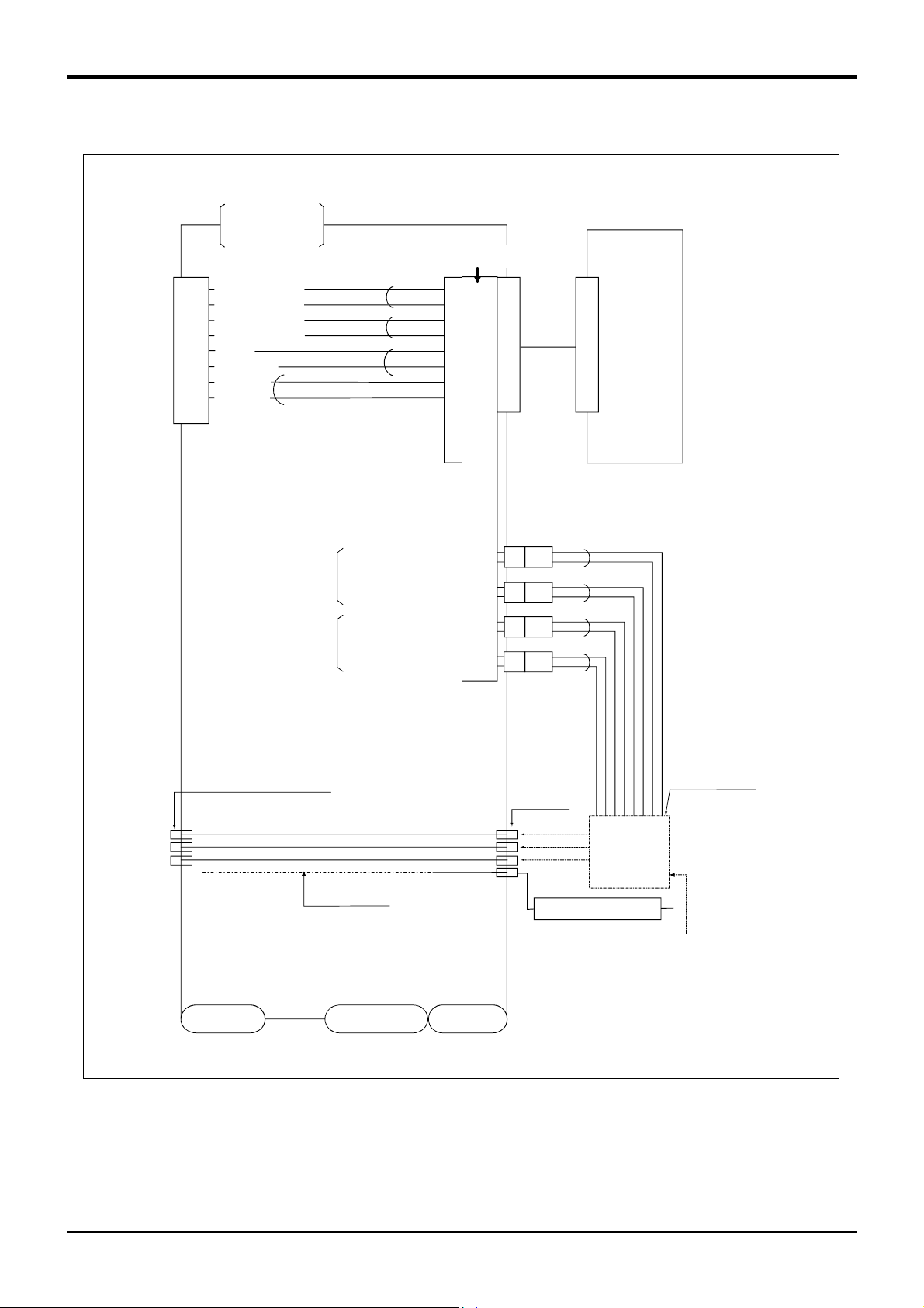
(2) RV-1AC-SB/2AJC-SB (Clean specification)
A
A
A
<Sink type>
2 Robot arm
During use of
pneumatic
hand I/F.
<Hand check 1>
1
<Hand check 2>
2
<Hand check 3>
3
<Hand check 4>
4
<+24V>
5
<0V(COM)>
6
<Not use>
7
<Not use>
8
9
White
Black
Hand 1
ON/OFF
Hand 2
ON/OFF
White
Black
White
Black
White
Black
General-purpose output
General-purpose output
General-purpose output
General-purpose output
General-purpose
input No.
900
901
902
903
900
+24V
901
+24V
902
+24V
903
+24V
GR1
1
2
GR2
1
2
GR3
1
2
GR4
1
2
White
Black
White
Black
White
Black
White
Black
Robot
controller
Solenoid valve
section
Solenoid valve
manifold
Connect to the
primary air supply
(φ6 hose)
-
IR OUT1
IR OUT2
IR OUT3
φ4 quick coupling bridge(1 to 4)
φ4 hose(4 hoses)
Internal suction
Wrist section
Shoulder section
Base section
φ4 quick
coupling
AIR IN1
AIR IN2
AIR IN3
AIR IN4
Vacuum solenoid valve
Solenoid valve
installation
section
(optional)
*Refer to Fig. 2-14 for air supply cir
cuit example.
Fig.2-12 : Wiring and piping system diagram for hand and example the solenoid valve installation(Sink type)
Tooling
2-19
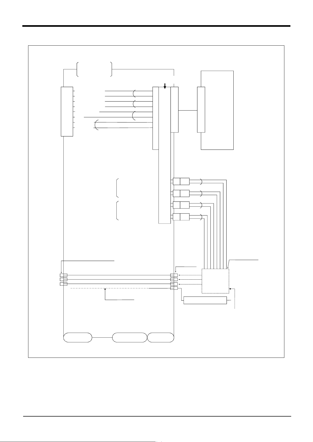
Page 28
2 Robot arm
A
A
A
<Source type>
During use of
pneumatic
hand I/F.
1
<Hand check 1>
2
<Hand check 2>
3
<Hand check 3>
4
<Hand check 4>
5
<24V(COM)>
6
<0V>
7
<Not use>
8
<Not use>
9
White
Black
Hand 1
ON/OFF
Hand 2
ON/OFF
White
Black
White
Black
White
Black
General-purpose output
General-purpose output
General-purpose output
General-purpose output
General-purpose
input No.
900
901
902
903
900
24G
901
24G
902
24G
903
24G
GR1
1
2
GR2
1
2
GR3
1
2
GR4
1
2
White
Black
White
Black
White
Black
White
Black
Robot
controller
Solenoid valve
section
Solenoid valve
manifold
Connect to the
primary air supply
(φ6 hose)
-
IR OUT1
IR OUT2
IR OUT3
φ4 quick coupling bridge(1 to 4)
φ4 hose(4 hoses)
Internal suction
Wrist section
Shoulder section
Base section
φ4 quick
coupling
AIR IN1
AIR IN2
AIR IN3
AIR IN4
Vacuum solenoid valve
*Refer to Fig. 2-14 for air supply cir
Solenoid valve
installation
section
(optional)
cuit example.
Fig.2-13 : Wiring and piping system diagram for hand and example the solenoid valve installation(Source type)
2-20
Tooling
Page 29

2.5.6 Electrical specifications of hand input/output
3.3K
820
0V
24V
HCn
*
24V(COM)
24V
(Internal power supply)
*
GRn
Fuse
1.6A
0V
Fuse
1.6A
*
GRn
24V
0V
Table 2-6 : Electrical specifications of input circuit
Item Specifications Internal circuit
Type DC input
No. of input points 4
Insulation method Photo-coupler insulation
Rated input voltage 12VDC/24VDC
Rated input current Approx. 3mA/approx. 7mA
Working voltage range DC10.2 to 26.4V(ripple rate within 5%)
ON voltage/ON current 8VDC or more/2mA or more
OFF voltage/OFF current 4VDC or less/1mA or less
Input resistance Approx. 3.3kΩ
Response time
OFF-ON 10ms or less(DC24V)
ON-OFF 10ms or less(DC24V)
<Sink type>
<Source type>
820
3.3K
24V
24V
*
HCn
0V(COM)
2 Robot arm
Table 2-7 : Electrical specifications of output circuit
Item Specification Internal circuit
Type Transistor output
No. of output points 4
Insulation method Photo coupler insulation
Rated load voltage DC24V
Rated load voltage range DC21.6 to 26.4VDC
Max. current load 0.1A/ 1 point (100%)
Current leak with power OFF 0.1mA or less
Maximum voltage drop with power ON DC0.9V(TYP.)
Response time OFF-ON 2ms or less (hardware response time)
ON-OFF 2 ms or less (resistance load) (hardware response time)
Fuse rating 1.6A (each one common) Cannot be exchanged
* HCn = HC1~HC4
<Sink type>
<Source type>
Note) An optional air hand interface (2A-RZ365/RZ375) is required to use hand output.
* GRn = GR1~GR4
Tooling
2-21
Page 30
2 Robot arm
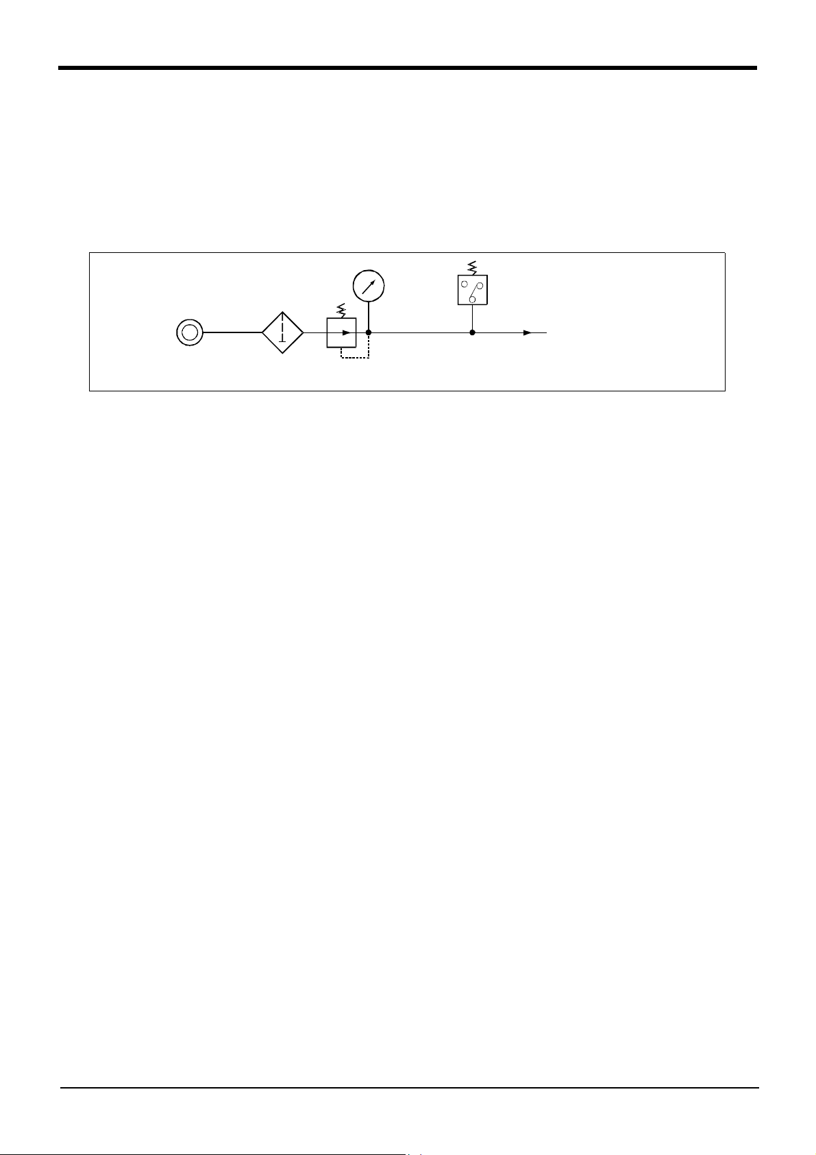
2.5.7 Air supply circuit example for the hand
Fig. 2-14 shows an example of pneumatic supply circuitry for the hand.
(1) Place diodes parallel to the solenoid coil.
(2) When the factory pneumatic pressure drops, as a result of the hand clamp strength weakening, there can be
damage to the work. To prevent it, install a pressure switch to the source of the air as shown in Fig. 2-14 and
use the circuit described so that the robot stops when pressure drops. Use a hand with a spring-pressure
clamp, or a mechanical lock-type hand, that can be used in cases where the pressure switch becomes dam
aged.
-
Pneumatic source
0.7MPa less
Filter
Regurater
Fig.2-14 : Air supply circuit example for the hand
Pressure switch
To the solenoid valve
primary air supply port
(0.5MPa
±10%)
2-22
Page 31

2.6 Shipping special specifications, options, and maintenance parts
2.6.1 Shipping special specifications
■ What are Sipping special specifications?
Shipping special specifications are changed at the time of shipment from the factory. Consequently, customer
need to confirm the delivery date.
To make changes to the specifications after shipment, service work must be performed at the work site or the
robot must be returned for service.
■ How to order
(1) Confirm beforehand when the Factory special specifications can be shipped, because they may not be
immediately available.
(2) Order before the factory shipping date.
(3) Specified method …… Specify the part name, model, and robot model type.
2 Robot arm
Shipping special specifications, options, and maintenance parts
2-23
Page 32

2 Robot arm
(1) Machine cable extension
■ Order type :●Fixed type(10m) :1A-10CBL-1
● Fixed type(15m) :1A-15CBL-1
● Flexed type(5m) :1A-05LCBL-1
● Flexed type(10m) :1A-10LCBL-1
● Flexed type(15m) :1A-15LCBL-1
■ Outline
This cable is exchanged with the standard machine cable (5m) accessory to extend
the distance between the controller and the robot arm.
A fixed type and flexible type are available.
Exchanges after shipment will be charged (for packaging, shipping costs).
The fixing and flexible types are both configured of the motor signal cable and motor
power cable .
■ Configuration
Table 2-8 : Configuration equipments and types
Part name Type
Motor signal cable (for fixed type) 1E- □□ CBL(S)-N 1 cable - 10m, or 15m each
Motor power cable (for fixed type) 1A- □□ CBL(P)-11 cable - 10m, or 15m each
Motor signal cable (for flexed type) 1E- □□ LCBL(S)-N - 1 cable 5m, 10m, or 15m each
Motor power cable (for flexed type) 1A- □□ LCBL(P)-1- 1 cable 5m, 10m, or 15m each
Nylon clamp NK-18N - 2 pcs.
Nylon clamp NK-14N - 2 pcs.
Silicon rubber - 4 pcs.
Note) The numbers in the boxes □□ refer the length.
Qty.
Fixed Flexed
Remarks
■ Specifications
The specifications for the fixed type cables are the same as those for standard cables.
Shows usage conditions for flexed type cables in Table 2-9.
Table 2-9 : Conditions for the flexed type cables
Item Specifications
Minimum flexed radius 100R or more
Cable bare, etc., occupation rate 50% or less
Maximum movement speed 2000mm/s or less
Warranty life (no.) 7.5 million times
Environmental proof Oil-proof specification sheath
Cable configuration Motor power cable Φ6.5x10
Motor signal cable Φ7x6 and Φ1.7x1
(for silicon grease, cable sliding lubricant type)
[Caution] The warranty life may greatly differ according to the usage state (items related to Table 2-9 and to the
amount of silicon grease applied in the cable conduit.
[Caution] This option can be installed on clean-type, but its cleanliness is not under warranty.
2-24
Shipping special specifications, options, and maintenance parts
Page 33

■ Cable configuration
The configuration of the flexible cable is shown in Table 2-10. Refer to this table when selecting the cable bare.
Table 2-10 : Cable configuration
Item
No. of cores
Finish dimensions
No.of cables used 6 cables
No. in total 7 cables 10 cables
AWG#24(0.2mm
Approx.
Motor signal cable
1E- □□ LCBL(S)-N
2
) -4P AWG#18(0.75mm2)AWG#18(0.75mm2) -3C
φ7mm
Approx.
1
cable
φ1.7mm
Motor power cable
1A- □□ LCBL(P)-1
10
φ6.5mm
cables
Approx.
Note. The square in the cable name indicates the cable length.
■ Fixing the flexible cable
(1) Connect the connector to the robot arm and controller.
(2) Wind the silicon rubber around the cable at a position 300 to 400 mm from the robot arm and controller as
shown in Fig. 2-15, and fix with the nylon clamp to protect the cable from external stress.
2 Robot arm
300~400mm
Nylon clamp
NK-14N
Nylon clamp
NK-18N
Nylon clamp
Fig.2-15 : Fixing the flexible cable
300~400mm
1A-□□LCBL(P)-1
1E-□□LCBL(S)-N
Nylon clamp
NK-14N
Nylon clamp
NK-18N
Silicon rubber
Shipping special specifications, options, and maintenance parts
2-25
Page 34

2 Robot arm
2.7 Options
■ What are options?
There are a variety of options for the robot designed to make the setting up process easier for customer needs.
customer installation is required for the options. Options come in two types: "set options" and "single options".
1. Set options ...................................... A combination of single options and parts that together, from a set for serving
some purpose.
2. Single options ................................. That are configured from the fewest number of required units of a part.
Please choose customer's purpose additionally.
■ Precautions for optional of motorized hand, pneumatic hand and solenoid valve
(1) About clean specification robot
The motorized hand, solenoid valve set and pneumatic hand can be installed, but its cleanliness is not under war
ranty.
(2) About customer manufactured hand
Though the motorized hand can't be manufactured by customer, the pneumatic hand can be manufactured.
Put the precaution together in the following.
-
Item
Pneumatic hand set
Motorized hand set
Solenoid valve set
Pneumatic hand This can be manufactured by customer
Motorized hand This cannot be manufactured by customer
General environment specification
RV-1A/2AJ
Installation possible
But the cleanliness cannot be guaranteed.
Clean specification
RV-1AC-SB/2AJC-SB
Installation possible
2-26
Options
Page 35

)
)
(1) Motorized hand set
■ Order type : 4A-HM01
■ Outline
・ Motorized hand and the required parts come in a set.
・ As air is not required, the hand can be used in laboratories.
・ The gripping force can be adjusted.
・ The life is 10,000,000 times at a 50% load. The 50% load refers to when the max. load
mass in Table 2-12 are all within 50%.
■ Configuration
Table 2-11 : Configuration equipment
Part name Type Qty. Remarks
Motorized hand 1A-HM011 pc.
Hand curl cable 1A-GHCD 1 pc.
Motorized hand I/F 2A-RZ364 1 pc.
Installation bolt (with hole) M3 × 84 bolts
M3 ×122 bolts
Hand adapter 1A-HA011 pc. The adapter for installing the motorized hand to the
robot's mechanical interface.
2 Robot arm
■ Specifications
Table 2-12 :
Drive method DC servo motor
Grip force 4.9 ~ 68.6N
Life 1,000,000 times cycle 100% load.
Repetition accuracy 0.03mm
Ambient temperature 0 to 40 ℃
Ambient humidity 45 to 85%
Atomosphere With no of oil mist, chip, powder dust.
Operation confirmation sensors None
Mass 0.59kg Including the adapter.
Maximum load per fin
ger
Motorized
hand specifications
Item Spacifications Remarks
(Each side grip is2.45 ~ 34.3N)
10,000,000 times cycle 50% load.
-
Radial 300N
Mpo moment 6.2N ・ m
Mro moment 10.8N ・ m
Myo moment 6.0N ・ m
RadialRadial
Radial
Radial
When installing the finger attachment, avoid
shock or excessive moment to the tips.
Others
Lp
LpLp
Lp
Mpo
Mpo
MpoMpo
Fp
Fp
FpFp
(=Lp*Fp)
(=Lp*Fp)
(=Lp*Fp)(=Lp*Fp)
Fr
Fr
FrFr
Mro
Mro
MroMro
(=Lr*Fr)
(=Lr*Fr)
(=Lr*Fr)(=Lr*Fr)
Lr
LrLr
Lr
The stroke cannot be adjusted.
Prepare the finger procured by the customer.
Ly
LyLy
Ly
Fy
Fy
FyFy
Myo
Myo
MyoMyo
(=Ly*Fy)
(=Ly*Fy
(=Ly*Fy)(=Ly*Fy
Options
2-27
Page 36

2 Robot arm
Motorized hand body
Adapter
1A-HA01
2-M3x12
(Hexagon socket bolt)
Approx. 70
4*2-M3
4-M3x8
(Hexagon socket bolt)
(From finger center)
4-Φ3.4 hole
(90 degree division)PCD70
(Φ6.5x4 spot facing on the
reverse side)
Hand body
Hand curl cable
Connector
160±10
Curl cable for bending
Fig.2-16 : Motorized hand outside dimensional drawing
(150)
φ11
40±10
Curl cable
Type 1A-GHCD
Connector
[Wiring system diagram]
Yellow
1
For
pneumatic
hand
DC+
DCReserve
Reserve
Reserve
Purple
2
Brown
5
Blue
6
Red
7
Black
8
3
4
9
6
5
4
3
1
2
2-28
Options
Page 37

)
)
(2) Pneumatic hand set
■ Order type: 4A-HP01 (Sink type)
4A-HP01E (Source type)
■ Outline
・ Pneumatic hand and the required parts come in a set.
・ The hand has a life of 10 million cycles.
・ There is a sensor at the open/close end.
■ Configuration
Table 2-13 : Configuration equipment
Part name Type
4A-HP01 4A-HP01E
Pneumatic hand 1A-HP011 pc. -
1A-HP01E-1 pc.
Hand curl tube (1 set: 2pc.) 1A-ST0402C 1 pc. 1 pc. Refer to the section on Page 35, "(6) Hand curl tube".
Curl cable 1A-GHCD 1 pc. 1 pc.
Pneumatic hand interface 2A-RZ365 1 pc. -
2A-RZ375 - 1 pc.
Solenoid valve set (1 set) 1E-VD011 pc. -
1E-VD01E-1 pc.
Installation bolt (with hole) M3 x 8 4 bolts 4 bolts
M3 x 12 4 bolts 4 bolts
Adapter 1A-HA011 pc. 1 pc. The adapter for installing the pneumatic hand to the robot's
■ Specifications
Table 2-14 : Pneumatic hand specifications
Item Spacifications Remarks
Operating fluid Clean air
Operating pressure range 0.04 to 0.7MPa
Operating temperature range 0 to 40 ℃
Open/close stroke
Life 10 million cycles or more
Operating method Double action
Mass 0.45kg Includes the adapter
Open/close confirmation sensor Open edge and close edge
Pneumatic coupling size Φ4 (quick coupling) Connection hose diameter: Φ4
Maximum load per finger Radial 700N
Mpo moment 6.2N ・ m
Mro moment 10.8N ・ m
Myo moment 6.0N ・ m
Qty.
Pneumatic hand body.
Refer to the section on Page 57, "(2) Pneumatic hand inter
face".
Refer to the section on Page 31, "(3) Solenoid valve set".
mechanical interface.
+2
12
mm
0
When installing the finger attachment, avoid shock or
excessive moment to the tips.
Remarks
2 Robot arm
-
Lp
LpLp
Lp
RadialRadial
Radial
Radial
Mpo
Mpo
MpoMpo
Fp
Fp
FpFp
(=Lp*Fp)
(=Lp*Fp)
(=Lp*Fp)(=Lp*Fp)
Fr
Fr
FrFr
Mro
Mro
MroMro
(=Lr*Fr)
(=Lr*Fr)
(=Lr*Fr)(=Lr*Fr)
Lr
LrLr
Lr
Ly
Ly
LyLy
Myo
Myo
MyoMyo
Fy
Fy
FyFy
(=Ly*Fy)
(=Ly*Fy
(=Ly*Fy)(=Ly*Fy
Options
2-29
Page 38

2 Robot arm
Pneumatic hand body
Adapter
Type:1A-HA01
4-M3x8
(Hexagon socket bolt)
Approx. 70
4-Φ3.4 hole
(90 degree division)PCD70
(Φ6.5x4 spot facing
on the reverse side)
(Hexagon socket bolt)
4-M3x12
Hand curl cable
Connector
160±10
Curl cable for bending
Hand body
5
8
24.5
(From finger center)
φ11
[Wiring system diagram]
<Sink type>
1
2
5
6
7
8
3
4
9
Yellow
Purple
Brown
Blue
Red
Black
6
5
4
3
1
2
(150)
40±10
Curl cable
Connector
For motorized hand
HC1(open)
HC2(close)
+24V
0V(COM)
Reserve
Reserve
Reserve
Type 1A-GHCD
<Source type>
70
60
50
40
10
20
HC1(open)
HC2(close)
+24V(COM)
For motorized hand
Reserve
Reserve
Reserve
Yellow
1
Purple
2
Brown
5
Blue
6
0V
Red
7
Black
8
3
4
9
6
5
4
3
1
2
30
20
Gripping force N
10
0.1 0.2
Pneumatic pressure MPa
Indication of gripping force and maximum
length of finger attachment
Fig.2-17 : Pneumatic hand outside dimensional drawing
2-30
Options
0.3
0.4
0.5
0.6
0.7
30
40
50
Attachment maximum length L cm
Page 39

(3) Solenoid valve set
■ Order type: One set: 1E-VD01(Sink type)/1E-VD01E(Source type)
Two sets: 1E-VD02(Sink type)/1E-VD02E(Source type)
■ Outline
The solenoid valve set is an option that is used for controlling toolings when various
toolings, such as the hand, are installed at the end of the arm. All have double sole
noid specification, and either one or two or three sets can be selected. This solenoid
valve set has a hand output cable attached to the solenoid valve. Also, for easy
installation of this electromaagnetic set onto the robot, it comes equipped with a
manifold, couplings, silencers, among other things.
When using the robot arm's hand output signal, the pneumatic hand interface option
must be installed on the separate controller.
■ Configuration
Table 2-15 : Configuration equipment
Part name Type
Solenoid valve set (1 set) 1E-VD01/
1E-VD01E
Solenoid valve set (2 sets) 1E-VD02/
1E-VD02E
■ Specifications
Table 2-16 : Valve specifications
Item Specifications
Number of positions 2
Port 5
Valve function Double solenoid
Operating fluid Clean air
Operating method Pilot type
Effective sectional area (CV value) 1.5mm(0.08)
Oiling Unnecessary
Operating pressure range 0.2 to 0.7MPa
Guaranteed proof of pressure 1.0MPa or more
Response time 12msec or less
Max. operating frequency 5c/s
Ambient temperature -5 to 50 ℃
Qty.
One set Two sets
1 pc. -
-1 pc.
Connecting the Page 34, "(5) Hand output cable".
M3x25 Two screws (Installation screws)
1E-VD01/VD02 are the sink type.
1E-VD01E/VD02E are the source type.
2 Robot arm
-
Remark
Table 2-17 : Solenoid specifications
Item Specifications
Method Built-in fly-wheel diodes with surge protection
Operation voltage DC24V ±10%
Current value 40mA
Insulation B type
Insulation resistance 100MΩ or more
Surge protection Fly-wheel diode
Options
2-31
Page 40

2 Robot arm
(1)
(12)
(3)
2- φ 3.3
GR3
GR1
GR2
GR4
SOL1A
SOL1B
SOL2A
SOL2B
28.4
36.4
(1)(4) (2)
(20)
or less
(5)
(6)
(45)
(10)(11)
Part
no.
(1) Solenoid valve 1 2
(2) Manifold block 11
(3) Quick coupling 2 4 φ4
(4) Block plate 1 0
(5) Quick coupling 11φ6
(6) Silencer 11
(10) Connector 2 4 SMR-09V-B
(11) Contact 4 8 SYM-001T-0.6
(12) Installation screw 2 2 M3x25
Part name 1 sets 2 sets Specifications
35.6
(82)
(28) (24)(30)
or less
<Sink type>
Black
SOL1A
SOL1B
SOL2A
SOL2B
Fig.2-18 : Outline dimensional drawing
2-32
Options
Red
Black
Red
Black
Red
Black
Red
General purposes
output 900
General purposes
output 901
General purposes
output 902
General purposes
output 903
Connector name
Hand1ON
1
+24V
2
Hand1OFF
1
+24V
2
1
Hand2ON
+24V
2
1
Hand2OFF
2
+24V
GR1
GR1
GR1GR1
GR2
GR2
GR2GR2
GR3
GR3
GR3GR3
GR4
GR4
GR4GR4
<Source type>
SOL1A
SOL1B
SOL2A
SOL2B
Black
Red
Black
Red
Black
Red
Black
Red
General purposes
output 900
General purposes
output 901
General purposes
output 902
General purposes
output 903
Connector name
Hand1ON
1
24G
2
Hand1OFF
1
24G
2
1
Hand2ON
24G
2
1
Hand2OFF
24G
2
GR1
GR1
GR1GR1
GR2
GR2
GR2GR2
GR3
GR3
GR3GR3
GR4
GR4
GR4GR4
Page 41

(4) Hand input cable
■ Order type: 1A-HC20
■ Outline
The hand input cable is used for customer-designed pneumatic hands.
It is necessary to use this to receive the hand's open/close confirmation signals and
grasping confirmation signals, at the controller.
One end of the cable connects to the connector for hand input signals, which is in
the wrist section of the hand. The other end of the cable connects to the sensor
inside the hand customer designed.
■ Configuration
Table 2-18 : Configuration equipment
Part name Type Qty. Remarks
Hand input cable 1A-HC20 1 cable
2 Robot arm
■ Specifications
Table 2-19 : Specifications
Item Specifications Remarks
Size x cable core
Total length 370mm (Including the curl section, which is 150mmlong)
AWG#24(0.2mm
2
) x 8 cores
(1)
φ11
60
±10
150
±10
160
(Yellow)
(Purple)
(Green)
(White)
(Brown)
(Blue)
(Red)
(Black)
±
10
SMR-09V-N
Sink
type type
HC1
1
HC2
2
HC3
3
HC4
4
+24V
5
0V(COM)
6
Reserve
7
Reserve
8
Reserve Reserve
9
Source
HC1
HC2
HC3
HC4
+24V(COM)
0V
Reserve
Reserve
Fig.2-19 : Outside dimensional drawing and pin assignment
[Caution] This option can be installed on clean-type, but its cleanliness is not under warranty.
Options
2-33
Page 42
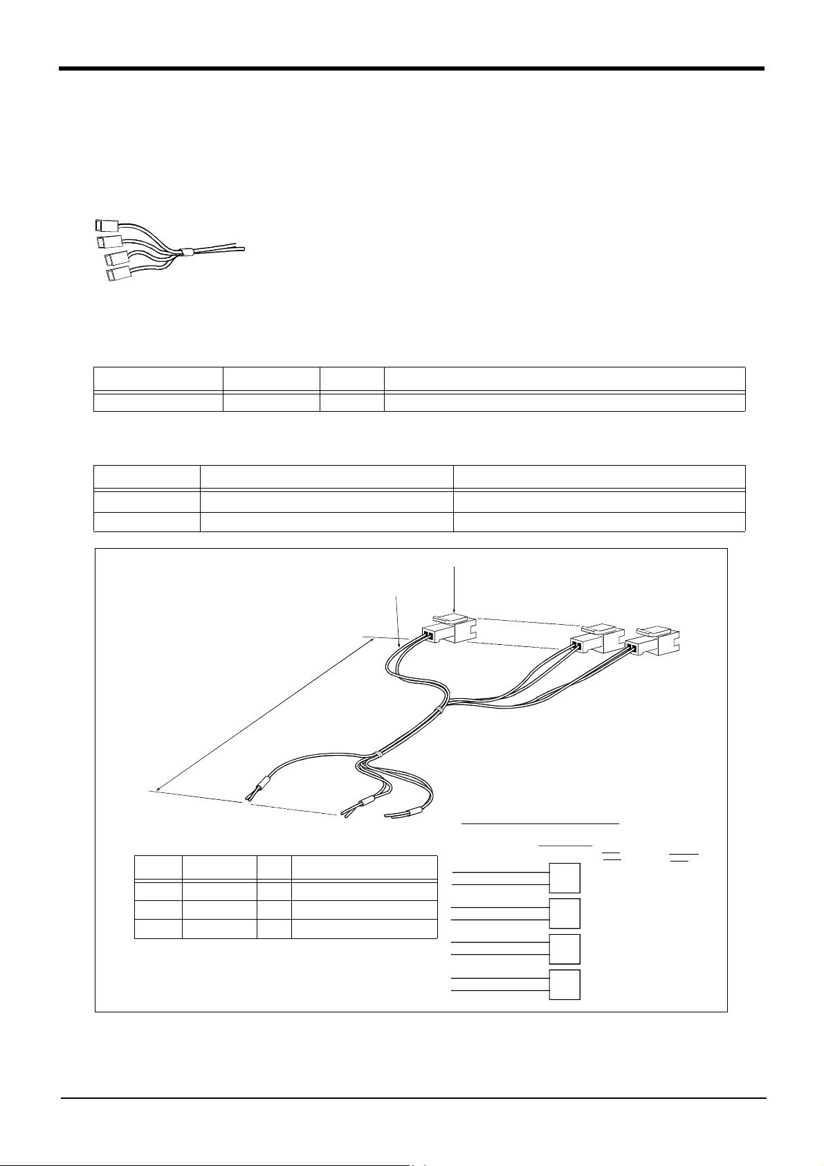
2 Robot arm
(5) Hand output cable
■ Order type: 1E-GR35S
■ Outline
The hand output cable (solenoid valve connection cable) is an option that is used
when an solenoid valve other than one of the solenoid valve set options, is used.
One end of the cable has a connector that connects to the connector on the back of
the robot arm. The other end of the cable is connected.
■ Configuration
Table 2-20 : Configuration equipment
Part name Type Qty. Remarks
Hand output cable 1E-GR35S 1 cable
■ Specifications
Table 2-21:Specifications
Item Specifications Remarks
Size x Cable core
Total length 350mm
AWG#22(0.3mm
2
) x 2 cores x 4 sets (total 8 cores)
One side connector and one side cable connection
350
*
・ Configuration
Part no. Part name Qty. Specifications
( 1 ) Connector 4 SMR-02V-B
( 2 ) Contact 8 BYM-001T-0.6
( 3 ) Twisted cable 4 AWG#22(0.3mm
*
2
) x 2 cores
*
(3)
(1)(2)
* End cable connection
Connector
general-purpose
White
Black
White
Black
White
Black
White
Black
output 900
general-purpose
output 901
general-purpose
output 902
general-purpose
output 903
1
2
1
2
1
2
1
2
GR1
GR2
GR3
GR4
Sink
type
Hand 1 ON
+24V
Hand 1 OFF
+24V
Hand 2 ON
+24V
Hand 2 OFF
+24V
Source
type
Hand 1 ON
+24G
Hand 1 OFF
+24G
Hand 2 ON
+24G
Hand 2 OFF
+24G
2-34
Fig.2-20 : Outline dimensional drawing and pin assignment
Options
Page 43

(6) Hand curl tube
■ Order type: One set (2 pcs.) : 1E-ST0402C
Two sets (4 pcs.) : 1E-ST0404C
■ Outline
The hand curl tube is a curl tube for the pneumatic hand.
■ Configuration
Table 2-22 : Configuration equipment
Part name Type Qty. Remarks
Hans curl tube (One set: 2 pcs.) 1E-ST0402C 1 pc. For single-hand: Φ4 tube, 2pcs.
Hans curl tube (Two set: 4 pcs.) 1E-ST0404C 1 pc. For double hand: Φ4 tube, 4pcs.
2 Robot arm
■ Specifications
This option can be installed on clean-type, but its cleanliness is not under warranty.
Table 2-23 : Specifications
Item Specifications
Material Urethane
Size Outside diameter: Φ4 x Inside diameter: Φ2.5
250
(Tooling side)
180
(Robot side)
200
φ28 (One set),
φ36 (Two sets)
Fig.2-21:Outline dimensional drawing
[Caution] This option can be installed on clean-type, but its cleanliness is not under warranty.
Options
2-35
Page 44

2 Robot arm
(7) Hand adapter
■ Order type : 1A-HA01
■ Outline
This is installed on the robot arm's mechanical interface.
The conventional model RV-M1 and the mechanical interface are compatible.
This is also included with the optional motorized hand set and pneumatic hand set.
■ Configuration
Table 2-24 : Configuration equipment
Part name Type Qty. Remarks
Adapter BU164D693H011 pc.
Installation bolt (with hole) M3 x 8 4 pc.
■ Specifications
Table 2-25 : Specifications
Item Specifications
Mass 0.07kg
Material Aluminum alloy
Fig.2-22 : Outline dimensional drawing
4-M3 screw hole
(4-constant pitch)
*For installation
4-3.4 reamer through
Φ6.5 counterbore
depth 4
(4-constant pitch)
Cross-section A-A
2-36
Options
Page 45

2 Robot arm
2.8 Maintenance parts
The consumable parts used in the robot arm are shown in Table 2-26. Purchase these parts from the designated
maker or dealer when required. Some Mitsubishi-designated parts differ from the maker's standard parts. Thus,
confirm the part name, robot arm and controller serial No. and purchase the parts from the dealer.
Table 2-26 : Consumable part list
No.
Part name Type Qty. Usage place Supplier
1 Lithium battery A6BAT 5 In the shoulder cover
2 Grrase SK-1A As needed Reduction gears of each axis
Mitsubishi Electric
Maintenance parts
2-37
Page 46

3Controller
3 Controller
3.1 Standard specifications
3.1.1 Standard specifications
Table 3-1:Standard specifications of controller
Item Unit Specification Remarks
Type CR1-571
Number of control axis Simultaneously 6(Maximum)
CPU 64 bit RISC, and DSP
Memory
capacity
Robot language MELFA-BASIC Ⅳ
Teaching method Pose teaching method ,MDI method
External
input and
output
Interface RS-232C port
Power
source
Outline dimensions mm 212(W)x290(D)x151(H) Excluding protrusions
Mass kg Approx. 8
Construction Self-contained floor type, Opened type
Operating temperature range deg. 0 to 40
Ambient humidity %RH 45 to 85 Without dew drops
Grounding Ω100 or less
Paint color Light gray Munsell 7.65Y7.64/0.73
Note1) It is the value when seven maximums expand (224/224) the Parallel I/O unit.
Note2) It is when an pneumatic hand interface (2A-RZ365 or 2A-RZ375) is installed. Note that the pneumatic
Note3) 1-phase,AC180 to 253. This specification is changed for CE-Marking model.
Note4) The power capacity (0.7kVA) is the maximum rating value for normal operation. The power capacity does
Note5) The controller (CR1-571) of this robot is a general environment specification. If the robot is used in an oil
Note6) The robot must be grounded by the customer.
Programmed positions and No.
of steps
Number of programs 88
input and output point 16/16
Dedicated input/output point Assigned with general-purpose input/output "STOP" 1 point is fixed
Hand open/close input/output
Emergency stop input/output point 1 Single emergency line
Door switch input point 1 Single door switch line
RS-422 port 1 Dedicated for T/B
Hand dedicated slot slot 1
Expansion slot slot 0 3 slot expansion is possible when
Robot input/output link channel 1
Input voltage range V 1-phase, AC90 to132
Power capacity KVA 0.7
point
step
MOVEMASTER COMMAND
point Input 4 point/Output 0 point
1-phase, AC180 to 253
2,500
5,000
or
1
Max. 240/240
Up to output points can be added as
an option
For expansion such as the personal
cpmputer, Vision sensor
Dedicated for pneumatic hand inter
face
using expansion option box.
Used for general-purpose input/out
put (Max. 240/240)
Note3)
Does not include rush current
Note5)
IP20
D class grounding earth
Note1)
Note2)
(2A-RZ361 or 2A-RZ371:Input 32 points / Output 32 points.)
hand interface has 8 output points, but the robot arm side has 4 points.
not include the rush current when the power is turned ON. The power capacity is a guideline and the actual
operation is affected by the input power voltage. The power consumption in the specific operation pattern
with the RV-1A/2AJ is approx. 0.2kw.
mist environment, use the optional controller protection box (CR1-MB) to protect the controller from the
oil mist environment. (Refer to Page 8, "2.2.3 Protection specifications and working environment")
Install to the place not to influence the cleanliness when using in the clean environment. (Refer toPage 9,
"2.2.4 Clean specifications")
Note6)
-
-
Note4)
3-38
Standard specifications
Page 47

3.1.2 Protection specifications and operating supply
A protection method complying with the IEC Standard IP20 (Opened type) is adopted for the controller.
IEC's IP symbols refer only to the degree of protection between the solid and the fluids, and don't indicated that
any special protection has been constructed for the prevention against oil and water.
Refer to the section Page 91, "5.2 Working environment" for details on the working environment.
If the robot is used in an oil mist environment, use the optional contorller protection box
CAUTION
(CR1-MB) to protect the controller from the oil mist environment.
Refer to the section Page 59, "(3) Controller protection box"for details on the controller
protection box.
3Controller
Standard specifications
3-39
Page 48

3Controller
3.2 Names of each part
<Front> <Front side of operation panel>
11)
14)
9)
STATUS NUMBER
MODE
TEACH
AUTO
(Op.)
2)
AUTO
(Ext.)
SVO OFF ST OP
7) 4) 15) 5)
SVO ON
CHANG DISP
START
UP
DOWN
RESET
END
EMG.STOP
REMOVE T/B
6)
1)
Front operation panel
12) 10) 13) 3)
8)
Fig.3-1:Names of controller parts
1) POWER switch ..................................... This turns the control power ON/OFF.
2) START button ...................................... This executes the program and operates the robot. The program is run continuously.
3) STOP button......................................... This stops the robot immediately. The servo does not turn OFF.
4) RESET button....................................... This resets the error. This also resets the program's halted state and resets the program.
5) Emergency stop switch .................... This stops the robot in an emergency state. The servo turns OFF.
6) T/B remove switch ............................This is used to connect/disconnect the T/B without turning OFF the controller's control
power.
7) CHNGDISP button.............................. This changes the details displayed on the display panel in the order of "Override" → "Pro
gram No." → "Line No.".
8) END button ............................................ This stops the program being executed at the last line or END statement.
9) SVO.ON button .................................... This turns ON the servo power. (The servo turns ON.)
10) SVO.OFF button ............................... This turns OFF the servo power. (The servo turns OFF.)
11) STATUS NUMBER
(display panel)...................................... The alarm No., program No., override value (%), etc., are displayed.
12) T/B connection connector ......... This is a dedicated connector for connecting the T/B.
13) Personal computer
connection connector ...................... This is an RS-232C specification connector for connecting the personal computer.
14) MODE key switch ............................. This changes the robot's operation mode.
AUTO (Op.) .................................. Only operations from the controller are valid. Operations for which the operation mode
must be at the external device or T/B are not possible.
TEACH........................................... When the T/B is valid, only operations from the T/B are valid. Operations for which the
operation mode must be at the external device or controller are not possible.
AUTO (Ext.) ................................. Only operations from the external device are valid. Operations for which the operation
mode must be at the T/B or controller are not possible.
15) UP/DOWN button ............................ This scrolls up or down the details displayed on the "STATUS. NUMBER" display panel.
Note)
-
3-40
Names of each part
Page 49

CAUTION
3Controller
Note) The servo will turn OFF when the controller's [MODE] switch is changed.
Note that axes not provided with brakes could drop with their own weight.
(6)
(7)
(5)
(1)
(2)
(4)
(3)
Fig.3-2 : Names of each controller part (Rear side)
(1) Machine cable connector (for motor power ) ....... Connects to the robot arm base. (CN1 connector)
(2) Machine cable connector (for motor signals)........ Connects to the robot arm base. (CN2 connector)
(3)Power supply terminals.
(4)Fuse box.
(5)External input/output signal connector.
(6)Network cable connector for parallel I/O unit expansion.
(7)Emergency stop switch and door switch terminals.
Names of each part
3-41
Page 50

3Controller
3.3 Outside dimensions/Installation dimensions
3.3.1 Outside dimensions
(170 or more)
(40)
STATUS NUMBER
MODE
TEACH
AUTO
(Op.)
AUTO
(Ext.)
CHANG DISP
SVO ON
START
SVO OFF STOP
UP
DOWN
RESET
END
290 (13)(38)
49 200
EMG.STOP
151 (15)
REMOVE T/B
150(31)(31)
(2.5) 212
Fig.3-3 : Outside dimensions of controller
3-42
Outside dimensions/Installation dimensions
(2.5)
Page 51

3.3.2 Installation dimensions
3Controller
50
STATUS NUMBER
AUTO
(Op.)
50
170 or more
DOWN
RESET
EMG.STOP
UP
REMOVE T/B
END
CHANG DISP
SVO ON
MODE
TEACH
AUTO
(Ext.)
SVO OFF
START
STOP
Fig.3-4 : Installation of controller
Outside dimensions/Installation dimensions
3-43
Page 52

3Controller
3.4 External input/output
3.4.1 Types
(1) Dedicated input/output .............................. These inputs and outputs carry out the robot remote operation and
status display.
(2) General-purpose input/output ................ These are inputs and outputs that the customer can program for
peripheral device control.
(3) Hand input/output ........................................ These are inputs and outputs related to the hand that the customer
can program. (The hand output is an option. The Page 57, "(2) Pneu
matic hand interface" is required.)
-
Class Name
Input Output
Standard Emergency stop 11Terminal block
Standard Door switch 1
Standard Parallel input/output Occupies 16 general-purpose points/(6)
dedicated points in general-purpose
No. of input/output points
Occupies 16 general-purpose points/(4)
dedicated points in general-purpose
Connection
format
Connector
3.4.2 Explanation
The parallel input/output unit uses connector bridging. Purchase the "External I/O cable" for connection with
external devices.
The hand output is an option. Refer to Page 57, "(2) Pneumatic hand interface" for details
The parallel input/output unit can be expanded outside of the controller.
The expansion parallel input/output unit is connected with the control unit in the controller using a robot I/O link
cable. Parallel input and output units can be expand as an option to seven maximums. With allows up to input 240
points and output 240 points of maximums can be used including 16 points input and 16 points output of standard.
Refer to Page 64, "(5) Parallel I/O unit" for details on the parallel input/output unit.
3-44
External input/output
Page 53

3.5 Dedicated input/output
Show the main function of dedicated input/output in the Table 3-2. Refer to attached instruction manual "CR1/
CR2/CR4/CR7/CR8 Controller Detailed explanations of functions and operations" in the product for the other
functions . Each parameter indicated with the parameter name is used by designated the signal No., assigned in
the order of input signal No. and output signal No. If the number of dedicated inputs and general-purpose input
points used exceeds the standard No. of input/output points, install the parallel input /output unit (1st to 7th sta
tion: option).
Table 3-2 : Dedicated input/output list
Parameter
name
TEACHMD None Teaching mode out
ATTOPMD None Automatic mode out
ATEXTMD None Remote mode output
AUTOENA Automatic opera
START Start input signal Starts all slots.
STOP Stop input signal Stops all slots.
SLOTINIT Slot initialization
ERRRESET Error reset input
CYCLE Cycle stop input
SRVOFF Servo ON enabled
SRVON Servo ON input
IOENA Operation rights
MELOCK Machine lock input
SAFEPOS Evasion point
OUTRESET General-purpose
EMGERR
S1START
:
S32START
S1STOP
:
S32STOP
PRGSEL Program selection
OVRDSEL Override selection
Name Function Level Name Function
-
tion enabled input
signal
input signal
signal
signal
input signal
signal
input signal
signal
return input signal
output signal reset
Start input Starts each slot. E In operation output
Stop input Stops each slot. L In wait output
input signal
input signal
Input
Disables automatic operation when
inactive, and enables automatic
operation when active.
The input signal No. is fixed to 0.
Note) Use the emergency stop
input for stop inputs related
to safety.
Resets the wait state, and initial
izes all slots.
Resets the error state.
Carries out cycle stop.
Sets all mechanisms to servo ON
enabled.
Turns the servo ON for all mecha
nisms.
Requests the operation rights for
the external signal control.
Sets/resets the machine lock
state for all mechanisms.
Requests the evasion point return
operation.
Resets the general-purpose output
signal.
None
esignates the setting value for the
program No. with numeric value
input signals.
esignates the setting value for the
override with the numeric value
input signals.
Note1)
put signal
put signal
signal
Automatic operation
L
enabled output signal
Operating output sig
E
nal
Wait output signal Outputs that the slot is temporarily
L
-
-
Program selection
E
enabled output signal
Error occurring out
E
put signal
In cycle stop opera
E
tion output signal
Servo ON enabled
L
output signal
In servo ON output
E
signal
Operation rights out
E
put signal
In machine lock out
E
put signal
In evasion point
E
return output signal
E None
Emergency stop out
put signal
E None
E None
Output
-
Outputs that the teaching mode is
entered.
-
Outputs that the automatic mode is
entered.
Outputs that the remote mode is
entered.
Outputs the automatic operation
enabled state.
-
Outputs that the slot is operating.
stopped.
Outputs that the slot is in the program
selection enabled state.
-
Outputs that an error has occurred.
-
Outputs that the cycle stop is operat
ing.
Outputs the servo ON enabled state.
(Echo back)
Outputs the servo ON state.
-
Outputs the operation rights valid state
for the external signal control.
-
Outputs the machine lock state.
Outputs that the evasion point return
is taking place.
-
Outputs that an emergency stop has
occurred.
Outputs the operating state for each
slot.
Outputs that each slot is temporarily
stopped.
3Controller
-
-
Dedicated input/output
3-45
Page 54

3Controller
Parameter
name
IODATA
Note2)
PRGOUT Program No. out
LINEOUT Line No. output
OVRDOUT Override value out
ERROUT Error No. output
JOGENA Jog valid input sig
JOGM Jog mode input 2-
JOG+ Jog feed + side for
JOG- Jog feed - side for
HNDERR1
:
HNDERR5
AIRERR1
:
AIRERR5
-
USER
Note3)
AREA
Name Function Level Name Function
Numeric value input
(start No., end No.)
-
put request
request
put request
request
nal
bit
8-axes
8-axes
Mechanism 1 hand
error input signal
:
Mechanism 5 hand
error input signal
Mechanism 1 pneu
matic pressure
error input signal
:
Mechanism 5 pneu
matic pressure
error input signal
Input
Used to designate the program No.,
override value., mechanism value.
Requests output of the program
No. E
Requests output of the line No.
-
Requests the override output.
Requests the error No. output.
-
Validates jog operation with the
external signals
Designates the jog mode.
Requests the + side jog operation. L None
Requests the - side jog operation. L None
Requests the hand error occur
rence.
-
Request the pneumatic pressure
error occurrence.
-
None
Note1)
Numeric value output
L
(start No., end No.)
Program No. output
signal
E Line No. output signal
Override value out
put signal
E
Error No. output sig
E
nal
Jog valid output sig
E
nal
Jog mode output 2-
L
bit
Mechanism 1 hand
-
error output signal
L
:
Mechanism 5 hand
error output signal
Mechanism 1 pneu
matic pressure error
output signal.
L
:
Mechanism 5 pneu
matic pressure error
output signal.
User-designated area
8-points
Used to output the program No., over
ride value., mechanism No.
Outputs that the program No. is being
output to the numeric value output sig
nal.
Outputs that the line No. is being out
put to the numeric value output signal.
-
Outputs that the override value is being
output to the numeric value output sig
nal.
-
Outputs that the error No. is being out
put to the numeric value output signal.
-
Outputs that the jog operation with
external signals is valid.
Outputs the current jog mode.
Outputs that a hand error is occurring.
-
Outputs that a pneumatic pressure
error is occurring.
-
Outputs that the robot is in the userdesignated area.
Output
-
-
-
-
-
Note1) The level indicates the signal level.
L: Level signal → The designated function is validated when the signal is ON, and is invalidated when the
signal is OFF.
E: Edge signal → The designated function is validated when the signal changes from the OFF to ON state,
and the function maintains the original state even when the signal then turns OFF.
Note2) Four elements are set in the order of input signal start No., end No., output signal start No. and end No.
Note3) Up to eight points can be set successively in order of start output signal No. and end output signal No.
3-46
Dedicated input/output
Page 55

3.6 Emergency stop input/output
This signal is input from the "emergency stop input" terminal in the controller.
Table 3-3 : Dedicated input terminals in controller
Class Name Details
Input Emergency stop Applies the emergency stop (Single emergency line.)
Input Door switch The servo turns OFF.
Output Emergency stop This output indicates that the emergency stop input or the door switch input is turned on.
3.6.1 Connection of the external emergency stop
The external emergency stop input and door switch input are short-circuited with a short cable at shipment as
shown in Fig. 3-5.
Connect the external emergency stop switch and door switch with the following procedure.
1) Prepare the "emergency stop switch" and "door switch".
2) Remove the two short pieces 1 and 2.
3) Securely connect the external emergency stop's contacts across "1)-2), and the door switch's contacts
across 3)-4)" on the terminal block.
24V
1
2
3
4
5
6
Emergency stop output
RA3
RA1
RA2
RG (24G)
Note1)
Emergency stop input
Door switch input
Short piece 1
Short piece 2
Composition of external emergency stop and door switch
3Controller
DOOR
Switch
EMG.
STOP
1
2
3
24V
System emergency
stop line
(Prepared by customer)
4
5
6
RA2
Wire insert
1)
2)
3)
4)
Controller rear side
Wire fixing screw
5)
RG (24G)
Example of wiring for external emergency stop and door switch
Output the system emergency stop output when either following the switch or the signal is turned on.
Note1)
・Emergency stop switch of the controller
・Emergency stop switch or deadman switch of the T/B
・External emergency stop input
・External door input
6)
Terminal block array of
external emergency stop
Fig.3-5 : Connection of the external emergency stop
[Note] Refer to Page 90, "5.1.7 Examples of safety measures" together, and carry out wiring to the emergency stop.
Emergency stop input/output
3-47
Page 56

3Controller
3.6.2 Door switch function
This function retrieves the status of the switch installed on the door of the safety fence, etc., and stops the robot
when the door is opened. This differs from an emergency stop in that the servo turns OFF when the door is
opened and an error does not occur. Follow the wiring example shown in Fig. 3-5, and wire so that the contact
closes when the door is closed. Details of this function according to the robot status are shown below.
During automatic operation ............. When the door is opened, the servo turns OFF and the robot stops. An error
occurs.
The process of the restoration : Close the door, reset the alarm, turn on the
servo, and restart
During teaching ...................................... Even when the door is opened, the servo can be turned ON and the robot
moved using the teaching pendant.
① Auto executing
Safeguard
TEACH
AUTO
(Op.)
② Teaching
TEACH
AUTO
(Op.)
AUTO
(Ext.)
AUTO
(Ext.)
Open
Open
Safeguard
STOP!!
Robot arm
(Example)
Turns OFF the servo
Teaching
Robot arm
pendant
(Example)
The servo can be turned ON/Off
by turning the deadman switch ON/OFF.
Fig.3-6 : Door switch function
3-48
Emergency stop input/output
Page 57

3.7 Parallel input/output unit
・ A parallel input/output card is mounted as a standard in the controller's control unit.
・ The external input/output circuit specifications are shown in Table 3-4 and Table 3-5.
・ The correspondence of the external input/output connector pin No. and the colors of the connected "external
input/output cable" wires (separate option) is as shown in Page 51, "Table 3-6"and Table 3-7. Refer to Page
72, "(6) External I/O cable" for details of external I/O cable.
・ Pin Nos. described as both general-purpose signal and dedicated signal can be shared.
・ The other dedicated input/output signals that are not assigned can be assigned to required general-purpose
input/output pins when creating the program.
・ If the standard inputs and outputs are insufficient, install the parallel input/output unit connection option out
side the controller.
Table 3-4 : Electrical specifications of input circuit
Item Specifications Internal circuit
Type DC input
No. of input points 16
Insulation method Photo-coupler insulation
Rated input voltage 12VDC/24VDC
Rated input current Approx. 3mA/approx. 7mA
Working voltage range 10.2VDC to 26.4VDC(ripple rate within 5%)
ON voltage/ON current 8VDC or more/2mA or more
OFF voltage/OFF current 4VDC or less/1mA or less
Input resistance Approx. 3.3kΩ
Response time
Common method 8 points per common
External wire connection
method
OFF-ON 10ms or less(DC24V)
ON-OFF 10ms or less(DC24V)
Connector
<Sink type>
<Source type>
820
3.3K
820
3.3K
24V/12V
(COM)
Input
Input
3Controller
-
Table 3-5 : Electrical specifications of output circuit
Item Specifications Internal circuit
Type Transistor output
No. of output points 16
Insulation method Photo-coupler insulation
Rated load voltage DC12V/DC24V
Rated load voltage range DC10.2 ~ 30V(peak voltage 30VDC)
Max. load current 0.1A/point (100%)
Leakage current at OFF 0.1mA or less
Max. voltage drop at ON DC0.9V(TYP.)
OFF-ON
Response time
ON-OFF
Fuse rating Fuse 3.2A (one per common) Replacement not pos
Common method 4 points per common (common terminal: 4 points)
External wire connection
method
External power
supply
Voltage DC12/24V(DC10.2 ~ 30V)
Current
2ms or less
(hardware response time)
2ms or less
(Resistance load) (hardware response time)
sible
Connector
60mA (TYP. 24VDC per common)
(base drive current)
<Sink type>
<Source type>
-
0V(COM)
(24/12V)
Outline
Fuse
(0V)
Fuse (24/12V)
Outline
(0V)
Parallel input/output unit
3-49
Page 58

3Controller
p
y
<Sink type>
Parallel I/O interface
(Output)
Fuse
(Input)
3.3K
60mA
(24/12V)
Output
…
…
Output
(0V)
External
power supply
(COM)
Input
…
…
Input
24V
24V
AX41C
(Mitsubishi programmable
controller)
+24V
COM
X
24G
AY51C
(Mitsubishi programmable
controller)
CTL+
24V
Y
COM
CTLG
External
power supply
24G
Fig.3-7 : Connection with a Mitsubishi PLC (Example of sink type)
*The input/output circuit external power supply (24 VDC) must be prepared by the customer.
<Source type>
(Output)
AX81C
60mA
Fuse
(24/12V)
Output
…
…
Output
X
24V
+
24V
COM
(Input)
(0V)
External
power supply
24G
CTL
+
24V
Input
3.3K
…
…
Input
(COM)
24V
Y
CTLG
24G
AY81C
External
ower suppl
Fig.3-8 : Connection with a Mitsubishi PLC (Example of source type)
*The input/output circuit external power supply (24 VDC) must be prepared by the customer.
3-50
Parallel input/output unit
Page 59

3Controller
Table 3-6 : Standard parallel I/O interface CN100pin No. and signal assignment list <Sink type> (2A-CBL
Pin
Line color
No.
1 Orange/Red A FG 26 Orange/Blue A FG
2 Gray/Red A 0V:For pins 4-7 27 Gray/Blue A 0V:For pins 29-32
3 White/Red A 12V/24V:For pins 4-7 28 White/Blue A 12V/24V:For pins 29-32
4 Yellow/Red A General-purpose output 0 Running 29 Yellow/Blue A General-purpose output 4
5 Pink/Red A General-purpose output 1 Servo on 30 Pink/Blue A General-purpose output 5
6 Orange/Red B General-purpose output 2 Error 31 Orange/Blue B General-purpose output 6
7 Gray/Red B General-purpose output 3 Operation rights 32 Gray/Blue B General-purpose output 7
8 White/Red B 0V:For pins 10-13 33 White/Blue B 0V:For pins 35-38
9 Yellow/Red B 12V/24V:For pins 10-13 34 Yellow/Blue B 12V/24V:For pins 35-38
10 Pink/Red B General-purpose output 8 35 Pink/Blue B General-purpose output 12
11 Orange/Red C General-purpose output 9 36 Orange/Blue C General-purpose output 13
12 Gray/Red C General-purpose output 10 37 Gray/Blue C General-purpose output 14
13 White/Red C General-purpose output 11 38 White/Blue C General-purpose output 15
14 Yellow/Red C
15 Pink/Red C General-purpose input 0
16 Orange/Red D General-purpose input 1 Servo off 41 Orange/Blue D General-purpose input 9
17 Gray/Red D General-purpose input 2 Error reset 42 Gray/Blue D General-purpose input 10
18 White/Red D General-purpose input 3 Start 43 White/Blue D General-purpose input 11
19 Yellow/Red D General-purpose input 4 Servo on 44 Yellow/Blue D General-purpose input 12
20 Pink/Red D General-purpose input 5 Operation rights 45 Pink/Blue D General-purpose input 13
21 Orange/Red E General-purpose input 6 46 Orange/Blue E General-purpose input 14
22 Gray/Red E General-purpose input 7 47 Gray/Blue E General-purpose input 15
23 White/Red E Reserved 48 White/Blue E Reserved
24 Yellow/Red E Reserved 49 Yellow/Blue E Reserved
25 Pink/Red E Reserved 50 Pink/Blue E Reserved
General-purpose Dedicated/power supply, common General-purpose
Function name
COM0:For pins 15-22
Stop(All slot)
Note2)
Note1)
Pin
Line color
No.
39 Yellow/Blue C
40 Pink/Blue C General-purpose input 8
Function name
Dedicated/power supply,
COM1:For pins 40-47
common
Note1)Sink type:24V/12V(COM), Source type:0V(COM)
Note2)The assignment of the dedicated input signal "STOP" is fixed.
□□
Note1)
)
Table 3-7 : Standard parallel I/O interface CN100pin No. and signal assignment list <Source type> (2A-CBL
Pin
Line color
No.
1 Orange/Red A FG 26 Orange/Blue A FG
2 Gray/Red A 0V:For pins 4-7, 10-13 27 Gray/Blue A 0V:For pins 29-32, 35-38
3 White/Red A 12V/24V:For pins 4-7, 10-13 28 White/Blue A 12V/24V:For pins 29-32, 35-38
4 Yellow/Red A General-purpose output 0 Running 29 Yellow/Blue A General-purpose output 4
5 Pink/Red A General-purpose output 1 Servo on 30 Pink/Blue A General-purpose output 5
6 Orange/Red B General-purpose output 2 Error 31 Orange/Blue B General-purpose output 6
7 Gray/Red B General-purpose output 3 Operation rights 32 Gray/Blue B General-purpose output 7
8 White/Red B Reserved 33 White/Blue B Reserved
9 Yellow/Red B Reserved 34 Yellow/Blue B Reserved
10 Pink/Red B General-purpose output 8 35 Pink/Blue B General-purpose output 12
11 Orange/Red C General-purpose output 9 36 Orange/Blue C General-purpose output 13
12 Gray/Red C General-purpose output
13 White/Red C General-purpose output
14 Yellow/Red C
15 Pink/Red C General-purpose input 0
16 Orange/Red D General-purpose input 1 Servo off 41 Orange/Blue D General-purpose input 9
17 Gray/Red D General-purpose input 2 Error reset 42 Gray/Blue D General-purpose input 10
18 White/Red D General-purpose input 3 Start 43 White/Blue D General-purpose input 11
19 Yellow/Red D General-purpose input 4 Servo on 44 Yellow/Blue D General-purpose input 12
20 Pink/Red D General-purpose input 5 Operation rights 45 Pink/Blue D General-purpose input 13
21 Orange/Red E General-purpose input 6 46 Orange/Blue E General-purpose input 14
22 Gray/Red E General-purpose input 7 47 Gray/Blue E General-purpose input 15
23 White/Red E Reserved 48 White/Blue E Reserved
24 Yellow/Red E Reserved 49 Yellow/Blue E Reserved
25 Pink/Red E Reserved 50 Pink/Blue E Reserved
General-purpose Dedicated/power supply, common General-purpose
10
11
Function name
COM0:For pins 15-22
Stop(All slot)
Note2)
Note1)
Pin
Line color
No.
37 Gray/Blue C General-purpose output 14
38 White/Blue C General-purpose output 15
39 Yellow/Blue C
40 Pink/Blue C General-purpose input 8
Function name
Dedicated/power supply,
common
COM1:For pins 40-47
□□
Note1)
Note1)Sink type:24V/12V(COM), Source type:0V(COM)
Note2)The assignment of the dedicated input signal "STOP" is fixed.
)
Parallel input/output unit
3-51
Page 60

3Controller
・The signals assigned as dedicated inputs can be used as general-purpose inputs during program execution. Note
that for safety proposes, these should not be shared with the general-purpose inputs other than for numeric
value inputs. The signals assigned as dedicated outputs cannot be used in the program. An alarm will occur dur
ing operation if used.
-
50
26
Connector pin layout
25
<CN100>
1
Output 0 to 15
Input 0 to 15
C o n t r o l l e r b a c k s i d e
*The I/O card in the control unit is equal to the PIO unit of the option.
(Input 32/Output 32 points)
Fig.3-9 : Parallel input/output unit (in the control unit) connection and pin layout
3-52
Parallel input/output unit
Page 61

3.8 Options
■ What are options?
There are a variety of options for the robot designed to make the setting up process easier for user needs.
User installation is required for the options.
Options come in two types: "set options" and "single options".
1. Set options......................................A combination of single options and parts that together, form a set for serving
some purpose.
2. Single options.................................That are configured from the fewest number of required units of a part.
Please choose user's purpose additionally.
3Controller
Options
3-53
Page 62

3Controller
(1) Teaching pendant (T/B)
■ Order type: R28TB :Cable length 7m
■ Outline
This is used to create, edit and control the program, teach the operation position and
for jog feed, etc.
For safety proposes, a 3-position deadman switch is mounted.
If there are several robots, one teaching pendant can be used by connecting it to the
respective robot.
■ Configuration
Table 3-8 : Configuration device
Part name Type Qty. Remarks
Teaching pendant R28TB One pc. Cable length is 7m. Hand strap is attached.
■ Specifications
Table 3-9 : Specifications
Items Specifications Remarks
Outline dimensions 95(W) x 236(H) x 34(D) (refer to outline drawing)
Body color Light gray (reference Munsell color: 7.65Y7.64/0.73)
Mass Approx. 0.5kg (only arm, excluding cable)
Connection method Connection with controller and round connector (30-pin)
Interface RS-422
Display method LCD method: 16 characters x 4 lines, LCD illumination: with backlight
Operation section 28 keys
Protection specifications IP65
Note2) The manual operation section of the teaching pendant has a protection method that complies with the IEC
Standards IP65 (protection type).
[Reference] The IEC Standards IP65 refers to installing the test device in the testing room, and suspending talc pow
der, which passes through a nominal dimension 75 μm mesh sieve, as specified with JISZ8001 (standard
sieve). This powder is continuously suspended around the device at a rate of 2kg per 1m3 volume of the
testing room. The air in the testing device is discharged at a discharge rate less than 60-times the volume
per hour. When the air is discharged at 80-times the test device capacity, the talc powder does not accu
mulate inside the test device even after eight hours.
Note1)
Note2)
-
-
Note1) <3-position deadman switch>
In ISO/10218 (1992) and JIS-B8433 (1993), this is defined as an "enable device". These standards specify that the
robot operation using the teaching pendant is enabled only when the "enable device" is at a specified position.
With the Mitsubishi Electric industrial robot, the above "enable device" is configured of an "Enable/Disable switch"
and "Deadman switch".
The 3-position deadman switch has three statuses. The following modes are entered according to the switch state.
"Not pressed" ............................... The robot does not operate.
"Pressed lightly" .......................... The robot can be operated and teaching is possible.
"Pressed with force" ................. The robot does not operate.
*)
*)
*) Operations, such as program editing and status display, other than robot operation are possible.
Safety is secured as the servo power is turned OFF simultaneously with the input of the emergency stop.
3-54
Options
Page 63

Hand strap
Contrast adjusting
switch
Display LCD
R28TB
Enable/Disable switch
DISABLE
ENABLE
3Controller
TOOL
JOINT
XYZ
MENU
STOP
$" :
=
( )?
# % !
/
*
55
70
203
Hand strap
SVO ON
STEP
MOVE
FORWD
BACKWD
COND
POS
ERROR
RESET
+
-
CHAR
X
X
-
+
(J1)
(J1)
ADD
Y
Y
-
+
(J2)
Z
-
(J3)
A
-
(J4)
B
-
(J5)
C
-
(J6)
↑
(J2)
RPL
Z
+
↓
(J3)
DEL
A
+
←
(J4)
HAND
B
+
→
(J5)
INP
C
+
EXE
(J6)
153
<Side> <Back> <Front>
EMG.STOP
Emergency stop
switch
Teaching pendant
Operation keys
Dead man switch
Cable
(with connection connector)
Fig.3-10 : Outside dimensions of teaching pendant
■ Installation method
The teaching pendant is connected to the T/B connector on the front of the controller.
Options
3-55
Page 64

3Controller
■ Key layout and main functions
19)
3)
4)
Back
7)
8)
9)
10)
18)
11)
12)
DISABLE
DISABLE
R28TB
R28TB
R28TBR28TB
DISABLEDISABLE
TOOL
TOOL
JOINT
JOINT
XYZ
XYZ
MENU
----
(J1)
(J1)
(J1)(J1)
----
(J2)
(J2)
(J2)(J2)
----
(J3)
(J3)
(J3)(J3)
----
(J4)
(J4)
(J4)(J4)
----
(J5)
(J5)
(J5)(J5)
----
(J6)
(J6)
(J6)(J6)
MENU
XYZXYZ
MENUMENU
STOP
STOP
(J1)
(J1)(J1)
(J2)
(J2)(J2)
(J3)
(J3)(J3)
(J4)
(J4)(J4)
(J5)
(J5)(J5)
(J6)
(J6)(J6)
++++
(J1)
++++
(J2)
++++
(J3)
++++
(J4)
++++
(J5)
++++
(J6)
# % !
# % !
# % ! # % !
X
X
X X
Y
Y
Y Y
Z
Z
Z Z
A
A
A A
B
B
B B
C
C
C C
STOPSTOP
ADD
ADD
ADD AD D
RPL
RPL
RPL RPL
DEL
DEL
DEL DEL
HAND
HAND
HAND HAND
↑↑↑↑
↓↓↓↓
←←←←
→→→→
INP
INP
INP INP
EXE
EXE
EXEEX E
$" :
$" :
$" : $" :
X
X
X X
Y
Y
Y Y
Z
Z
Z Z
A
A
A A
B
B
B B
C
C
C C
TOOLTOOL
JOINTJOINT
=
=
(
( ))))????
/
= =
( (
****///
SVO ON
SVO ON
SVO ONSV O ON
STEP
STEP
STEP STEP
MOVE
MOVE
MOVEMOVE
++++
FORWD
FORWD
FORWDFORWD
----
BACKWD
BACKWD
BACKWDBACKWD
COND
COND
CONDCOND
POS
POS
POS POS
CHAR
CHAR
CHARCH AR
ERROR
ERROR
ERROR ERROR
RESET
RESET
RESETRESET
ENABLE
ENABLE
ENABLEENABLE
EMG.STOP
EMG.STOP
EMG.STOPEMG.STOP
2)
5)
1)
6)
13)
14)
15)
16)
17)
1) : Emergency stop switch...................The robot servo turns OFF and the operation stops immediately.
2) : T/B enable/disable
changeover switch............................This switch changes the T/B key operation between enable and dis
-
able.
3) : LCD display panel .............................The robot status and various menus are displayed.
4) : <TOOL, JOINT, XYZ> key .............This selects the jog mode (JOINT, XYZ, 3-AXIS XYZ, CYLINDER,
TOOL).
5) : <MENU> key........................................This returns the display screen to the menu screen.
6) : <STOP> key ........................................This stops the program and decelerates the robot to a stop.
7) : <STEP/MOVE> key..........................Jog operation is carried out when this key is pressed simultaneously
with the jog operation key. This also turns the Servo ON and carries
out step jump.
8) : <( + FORWD> key............................This carries out step feed and increases the override.
9) : <( - BACKWD> key.........................This carries out step return (return along operation path) and
decreases the override.
10) : <COND> key .....................................This sets the program.
11) : <ERROR RESET> key...................This resets the error, and releases the software limit.
12) : Jog operation key ...........................This operates the robot according to the jog mode. When inputting
numeric values, this inputs each numeric value.
13) : <ADD/ ↑ > key ...............................This additionally registers the position data. It also moves the cursor
upward.
14) : <RPL/ ↓ > key................................This corrects the position data. It also moves the cursor downward.
15) : <DEL/ ← > key................................This deletes the position data. It also moves the cursor to the left.
16) : <HAND/ → > key............................This opens and closes the hand. It also moves the cursor to the right.
17) : <INP/EXE> key................................This inputs the program, and carries out step feed/return.
18) : <POS CHAR> key...........................This changes the edit screen, and changes between numbers and
alphabetic characters.
19) : Deadman switch ..............................When the [Enable/Disable] switch "2)" is enabled, and this key is
released or pressed with force, the servo will turn OFF, and the oper
ating robot will stop immediately.
-
Fig.3-11 : Teaching pendant key layout and main functions
3-56
Options
Page 65

(2) Pneumatic hand interface
24V
(Internal power supply)
*
GRn
Fuse
1.6A
0V
■ Order type: 2A-RZ365(Sink type)
2A-RZ375(Source type)
■ Outline
This interface is required to use the robot arm's hand output signals.
・ Up to eight hand output points can be used with this interface.
・ The eight hand input points can be used without this interface.
・ When using more than eight hand input/output points, install the "Parallel I/O
unit". Refer to Page 64, "Parallel I/O unit" for detail.
■ Configuration
Table 3-10 : Configuration device
Part name Type Qty. Remarks
Pneumatic hand interface 2A-RZ365/
2A-RZ375
Output 8 point expansion. 2A-RZ365 is the sink type.
1pc.
2A-RZ375 is the source type.
3Controller
■ Specifications
Table 3-11 : Specifications
Item Specification Internal circuit
Type Transistor output
No. of output points
Insulation method Photo coupler insulation
Rated load voltage DC24V
Rated load voltage range DC21.6 to 26.4VDC
Max. current load 0.1A/ 1 point (100%)
Current leak with power OFF 0.1mA or less
Maximum voltage drop with power ON DC0.9V(TYP.)
Response time OFF-ON 2ms or less (hardware response time)
ON-OFF 2 ms or less (resistance load) (hardware response time)
Fuse rating Fuses 1.6A (each one common)
Common method 8 points, 1 common
External cable connection method
Supply voltage DC5V (Supplied from RZ386 or RZ387)
Note1)
8
Connector (Connected from RZ386 or RZ387)
Note2)
<Sink type>
<Source type>
Fuse
1.6A
24V
GRn
*
Note1)Wiring to the robot side will differ according to the model. The No. of output points that can be used will differ according
Note2)RZ386:The control card mounted on the controller of the sink type.
to the state of the wiring on the robot arm side. Example) RV-1A/2AJ has 4 points.
RZ387:The control card mounted on the controller of the source type.
0V
* GRn = GR1~GR8
Options
3-57
Page 66

3Controller
■ Installation method
This is mounted on the control unit (RZ386 or RZ387 card) in the controller.
Securely insert the pneumatic hand interface (2A-RZ365/375) into the CNHNDOUT/CNHND connector on the
control unit.
RZ386 or RZ387 card
Control unit
A
<RZ386>
<RZ387>
or
CNHND
CNHND
CNHNDOUT
2A-RZ365
CNHNDOUT
or
2A-RZ375
View A
Fig.3-12 : Installation of pneumatic hand interface
Note)The hand output doesn't work correctly in the case of "RZ386" + "RZ365" or "RZ387" + "RZ375" combi
nation.
Choose either of sink type/source type properly, and use it.
3-58
Options
-
Page 67

(3) Controller protection box
■ Order type : ● CR1-MB
■ Outline
The controller protection box is used to protect the CR1-571 controller from an oil
mist or other operating environment. Put the controller and the earth leakage
breaker, etc. in controller protection box, and use it. Since the front cover of the
controller protection box can be removed, it is possible to operate the controller's
front panel and to install and remove the T/B.
■ Configuration
Table 3-12 : Configuration device
Part name Type Qty. Remarks
Controller protection box CR1-MB 1 unit
Serial number posting label 1
Protection seal transparent 1 Protection for the serial number posting label.
Cable tie 2
Power supply wiring cable 1 For connecting the power relay terminal and the controller inside the box.
Grounding cable 1 For connecting the FG terminal and the controller inside the box.
External emergency stop box
(Controll box)
HW1X-BV401R 1 unit Single emergency line. Install at a location outside the controller protection
box where operation can be performed easily. The outside dimensions is
shown in Fig. 3-15.
3Controller
■ Specifications
Table 3-13 : Specifications
Item Unit Specifications Remarks
Outside dimensions mm 414(W) × 492(D) × 202(H) Excluding protrusions
Mass Kg 10
Structure Self-contained floor type IP54
Grounding D class grounding earth
Coating color Light gray Munsell 7.65Y7.64/0.73
(1) The installation of the controller, earth leakage breaker and wiring are constructed by customer.
(2) Prepare the 2 power cable and 1 grounding cable (both AWG#14(2mm
2
) or more).
(3) The emergency stop box does not come with a cable clamp (wiring connector). The cable clamp must be
provided by the customer according to the size of the cable.
The following table shows recommended cable clamps for your reference.
Table 3-14 : Cable clamp for external emergency stop box (recommendation)
Type JIS wiring tube Adaptation cable outside diameter Manufacturer
OA-W1606
OA-W1608 6 ~ 8φ
OA-W1609 7 ~ 9φ
OA-W1611 9 ~ 11φ
OA-W1613 11 ~ 13φ
G1/2
4 ~ 6φ
OHM electric Corp
Options
3-59
Page 68

3Controller
■ Names of each part
<Front>
Chassis cover (Top board)
Window
Front panel
Corner type catch clip
Fig.3-13 : Names of controller parts
■ The outside dimension and controller layout
<Rear>
Cable cover
Rear panel
Cable cover
(Machine cable for power)
Cable cover
(Machine cable for signal)
Heat exchanger
CR1-571 controller
arrangement place
Window
(52) (52)
(21.5) (21.5)
310
414
Fig.3-14 : The outside dimension and controller layout
492
306 91.292.2 100
187(15)
3-60
Options
Page 69

■ The outside dimensions and installation dimensions of emergency stop box
3Controller
Operation switch
TOP
□ 70.0
BOX cover installation screw
TOP
2-φ4.6
(Two M4 installation
screw holes)
58.0
BOX cover
32.0 58.0
42.4
BOX base
*The M4 screw prepared by customer
Panel installation dimension
Fig.3-15 : The outside dimensions and installation dimensions of emergency stop box
φ23.0 conduit
(Knockout)
■ Installation dimensions
150mm or more
Note)
150mm or more
150mm or more
Note)
Note)
Keep the space of
150mm or more for
opening and closing
the corner type catch clip.
Fig.3-16 : Installation of controller
Options
3-61
Page 70
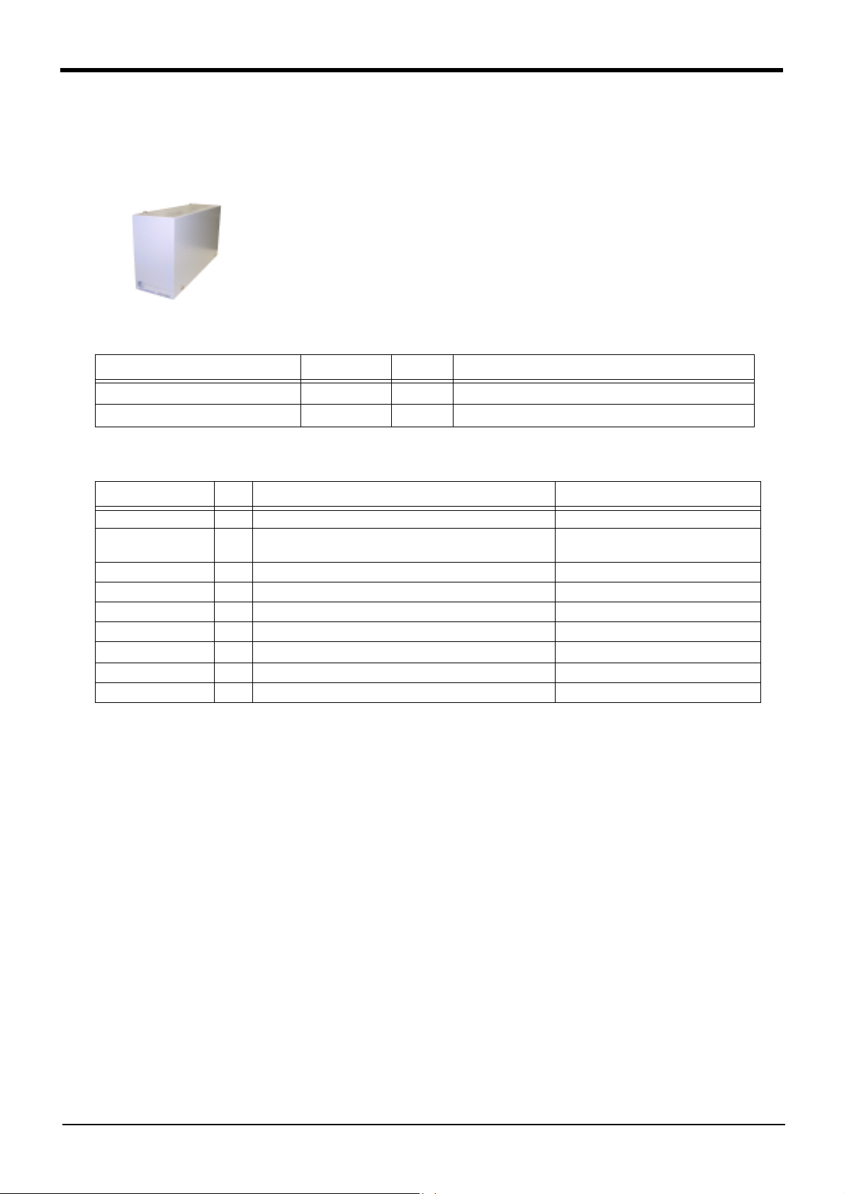
3Controller
(4) Expansion option box
■ Order type : ● CR1-EB3
■ Outline
By installing this expansion option box to the side of the CR1-571 controller, the
expansion serial interface, CC-Link interface and Ethernet interface can be used.
Up to three option cards can be mounted.
■ Configuration
Table 3-15 : Configuration device
Part name Type Qty. Remarks
Expansion option box
Installation screw
CR1-EB3 1
4
With rubber foot
■ Specifications
Table 3-16 : Specifications
Item Unit Specifications Remarks
Number of slot slot 3 RT-Bus 1, 2, 3
Power supply method Power supply is supplied from controller by
the RT-Bus coupling(+5V/SG)
Current value A Max. 3 Max. 1A/slot
Ambient temperature deg. 0 to 40
Ambient humidity %RH 45 to 85 Without dew drops
Grounding D class grounding earth Grounding from external terminal
Structure Self-contained floor type opened structure
Outside dimensions mm 85(W) x 290(D) x 165(H)
Mass kg Approx. 3
Note1)
Note1) Self-contained floor type, under the condition combined with the body.
3-62
Options
Page 71

Installation of expansion option box
3Controller
Expansion option box
60
24
151
(15)
65
Rear side
cable outlet
CR1-571 controller
299.7
87.5
Installation
screw
Four
positions
42
(38)
Positioning latch Positioning latch
290
(13)
Layout of expansion option box
Plates with rails
(Two positions)
Fan
Fig.3-17 : Outside dimensions and layout
Slot1
Slot2
Slot3
Installation screw(Four positions)
The example which an option
card was mounted to.
Controller connection connector
Positioning latch
Grounding terminal(M4)
■ Installation method
Remove the side plate of the CR1-571 controller, connect the connectors, and fix to the controller with the four
fixing screws in the expansion option box.
The option cards mounted in the slot are fixed with the plates with rails.
The cables required for the option card are lead out from the cable outlet on the rear side.
Options
3-63
Page 72

3Controller
(5) Parallel I/O unit
■ Order type: 2A-RZ361(Sink type)
2A-RZ371(Source type)
■ Outline
This is used to expand the external inputs and outputs.
・ The connection cable is not included. Prepare the optional external input/output
cable (2A-CBL05 or 2A-CBL15).
■ Configuration
Table 3-17 : Configuration device
Part name Type Qty. Remarks
Parallel I/O unit
Robot I/O link connection connector
Power connection connector
Terminator R-TM 1150Ω(1/4W)
2A-RZ361/
2A-RZ371
NETcable-1 2 sets
DCcable-2 1 sets
1
Input/output 32 points/32 points
2A-RZ361 is the sink type.
2A-RZ371 is the source type.
Connector with pins.
The cable must be prepared and wired by the customer.
Connector with pins.
The cable must be prepared and wired by the customer.
■ Specifications
1) Up to eight stations can be connected to this unit. (One station occupies one unit.)
One unit is built into the controller as a standard, so up to seven units can be installed as expansions.
2) The power supply (24V) must be prepared by the customer and connected with the power connection cable
(DCcable-2)
A separate 24V power supply is required for the input/output circuit wiring.
The detailed specifications of the input/output circuit are the same as the parallel input/output unit mounted as a
standard. Refer to Page 49, "3.7 Parallel input/output unit" for details.
Table 3-18 : Electrical specifications of input circuits
Item Specification Internal circuit
Type DC input
Number of input points 32
Insulation method Photo coupler insulation
Rated input voltage DC12V/DC24V
Rated input current Approx 3mA/7mA
Working voltage range DC10.2 to 26.4V(Ripple factor should be less than 5%.)
ON voltage/ON current 8VDC or more/ 2mA or more
OFF voltage/ OFF current 4VDC or less/ 1mA or less
Input resistance Approx. 3.3kΩ
Response time OFF-ON 10ms or less (24VDC)
ON-OFF 10ms or less (24VDC)
Common method 8 point 1 common
External cable connection method Connector
<Sink type>
820
<Source type>
820
3.3K
3.3K
24V/12V
(COM)
Input
Input
3-64
Options
0V(COM)
Page 73

Table 3-19 : Electrical specifications for the output circuits
Item Specification Internal circuit
Type Transistor output
No. of output points 32
Insulation method Photo-coupler insulation
Rated load voltage DC12V/DC24V
Rated load voltage range DC10.2 ~ 30V(peak voltage 30VDC)
Max. load current 0.1A/point (100%)
Leakage current at OFF 0.1mA or less
Max. voltage drop at ON DC0.9V(TYP.)
OFF-ON
Response time
ON-OFF
Fuse rating Fuse 3.2A (one per common) Replacement not possible
Common method 4 points per common (common terminal: 4 points)
External wire connection
method
External power
supply
Voltage DC12/24V(DC10.2 ~ 30V)
Current 60mA (TYP. 24VDC per common) (base drive current)
2ms or less
(hardware response time)
2ms or less
(Resistance load) (hardware response time)
Connector
<Sink type>
<Source type>
(24/12V)
Outline
Fuse
(0V)
Fuse (24/12V)
Outline
(0V)
3Controller
NETcable-1 (Network cable)
Pin No. RIO1/2 RIO1/2 Pin No.
1 TXRXH TXRXH 1
2 TXRXL TXRXL 2
3 SG(GND) SG(GND) 3
Note 2)
FG
DCcable-2 (Power cable)
Pin No. DCIN
1 24V +
2 24G(RG) -
3 FG(PE)
24V Power
Note 1)
Connected the frame ground or protect ground
R-TM (Terminator)
Pin No. RIO1/2 150Ω
1 TXRXH
2 TXRXL
3 SG(GND)
List of parts and manufacturer
Type Connector type Contact type Resistant Manufacturer
NETcable-11-178288-3 (2) 175218-3 (6) - AMP
DCcable-2 2-178288-3 (1) 175218-3 (3) - AMP
R-TM 1-178288-3 (1) 175218-3 (2) 150Ω(1/4W) (1) Equivalent to KOA.
Note 1) The 24V power supply is prepared by customer (The power consumption is approx. 0.3A.)
Note 2) The cable for general purpose can be used to the network cable. However, use the twisted shield cable of
AWG#22(0.3mm
2
) or more.
Fig.3-18 : Spacifications for the connection cable
Options
3-65
Page 74

3Controller
■ Installation method
The expansion parallel input/output unit is installed outside of the controller. Connect with the network connec
tion cable (NETcable-1) from the RIO1 connector in the rear of the controller.(Terminator is connected at the
time of shipment)
RIO1 connector
-
(40)
Wiring
space
upside
(175)
128
<2A-RZ361>
100
6
Heat radiation space
54 6
60
Control panel installation dimensions
150
2-M5 screw
6
156
168
6
downside
Fig.3-19 : Installing the parallel input/output unit
3-66
Options
Radiation/wiring space
Installation dimensions of 2A-RZ361
(The controller outside installation.)
Page 75

RIO1 connector
3Controller
Controller back side
Station No. setting
1 . . . 6
Note)
NETcable-1
cable
RIO1 connector
<CN100>
FG
DCcable-2
cable
Parallel I/O unit
DCIN
connector
Front
1 . . . 6
<CN300>
RIO2 connector
RIO1 connector
Station No. setting
7
Note)
NETcable-1
cable
<CN100>
RIO1 connector
FG
DCcable-2
cable
Parallel I/O unit 7
DCIN
connector
<CN300>
RIO2 connector
R-TM
terminator
RIO2 connector
DCIN connector
I/O unit the bottom
Connecta layout
Connect the NET cable-1 to the RIO1 connector on the back of the controller. Each unit is
connected to from a daisy chain.
Always install a terminator (R-TM) to the last unit.
Note) Use a shield cable for NET cable-1 as a measure against noise.
Always connect the shield to FG.
The unit could malfunction because of noise if the shield cable is not used.
Fig.3-20 : Connection method of expansion parallel input/output unit
Options
3-67
Page 76

3Controller
■ Parallel I/O interface (First expansion unit)
Table 3-20 : Connector CN100pin No. and signal assignment list (2A-CBL
Pin
Line color
No.
1 Orange/Red A FG 26 Orange/Blue A FG
2 Gray/Red A 0V:For pins 4-7 27 Gray/Blue A 0V:For pins 29-32
3 White/Red A 12V/24V:For pins 4-7 28 White/Blue A 12V/24V:For pins 29-32
4 Yellow/Red A General-purpose output 32 29 Yellow/Blue A General-purpose output 36
5 Pink/Red A General-purpose output 33 30 Pink/Blue A General-purpose output 37
6 Orange/Red B General-purpose output 34 31 Orange/Blue B General-purpose output 38
7 Gray/Red B General-purpose output 35 32 Gray/Blue B General-purpose output 39
8 White/Red B 0V:For pins 10-13 33 White/Blue B 0V:For pins 35-38
9 Yellow/Red B 12V/24V:For pins 10-13 34 Yellow/Blue B 12V/24V:For pins 35-38
10 Pink/Red B General-purpose output 40 35 Pink/Blue B General-purpose output 44
11 Orange/Red C General-purpose output 41 36 Orange/Blue C General-purpose output 45
12 Gray/Red C General-purpose output 42 37 Gray/Blue C General-purpose output 46
13 White/Red C General-purpose output 43 38 White/Blue C General-purpose output 47
14 Yellow/Red C COM0:For pins 15-22
15 Pink/Red C General-purpose input 32 40 Pink/Blue C General-purpose input 40
16 Orange/Red D General-purpose input 33 41 Orange/Blue D General-purpose input 41
17 Gray/Red D General-purpose input 34 42 Gray/Blue D General-purpose input 42
18 White/Red D General-purpose input 35 43 White/Blue D General-purpose input 43
19 Yellow/Red D General-purpose input 36 44 Yellow/Blue D General-purpose input 44
20 Pink/Red D General-purpose input 37 45 Pink/Blue D General-purpose input 45
21 Orange/Red E General-purpose input 38 46 Orange/Blue E General-purpose input 46
22 Gray/Red E General-purpose input 39 47 Gray/Blue E General-purpose input 47
23 White/Red E Reserved 48 White/Blue E Reserved
24 Yellow/Red E Reserved 49 Yellow/Blue E Reserved
25 Pink/Red E Reserved 50 Pink/Blue E Reserved
General-purpose
Function name
Dedicated/power supply,
common
Pin
No.
Note1)
39 Yellow/Blue C COM1:For pins 40-47
Note1)Sink type:24V/12V(COM), Source type:0V(COM)
Line color
)
□□
General-purpose
Function name
Dedicated/power supply,
common
Note1)
Table 3-21:Connector CN300pin No. and signal assignment list (2A-CBL
Pin
Line color
No.
1 Orange/Red A FG 26 Orange/Blue A FG
2 Gray/Red A 0V:For pins 4-7 27 Gray/Blue A 0V:For pins 29-32
3 White/Red A 12V/24V:For pins 4-7 28 White/Blue A 12V/24V:For pins 29-32
4 Yellow/Red A General-purpose output 48 29 Yellow/Blue A General-purpose output 52
5 Pink/Red A General-purpose output 49 30 Pink/Blue A General-purpose output 53
6 Orange/Red B General-purpose output 50 31 Orange/Blue B General-purpose output 54
7 Gray/Red B General-purpose output 51 32 Gray/Blue B General-purpose output 55
8 White/Red B 0V:For pins 10-13 33 White/Blue B 0V:For pins 35-38
9 Yellow/Red B 12V/24V:For pins 10-13 34 Yellow/Blue B 12V/24V:For pins 35-38
10 Pink/Red B General-purpose output 56 35 Pink/Blue B General-purpose output 60
11 Orange/Red C General-purpose output 57 36 Orange/Blue C General-purpose output 61
12 Gray/Red C General-purpose output 58 37 Gray/Blue C General-purpose output 62
13 White/Red C General-purpose output 59 38 White/Blue C General-purpose output 63
14 Yellow/Red C
15 Pink/Red C General-purpose input 48 40 Pink/Blue C General-purpose input 56
16 Orange/Red D General-purpose input 49 41 Orange/Blue D General-purpose input 57
17 Gray/Red D General-purpose input 50 42 Gray/Blue D General-purpose input 58
18 White/Red D General-purpose input 51 43 White/Blue D General-purpose input 59
19 Yellow/Red D General-purpose input 52 44 Yellow/Blue D General-purpose input 60
20 Pink/Red D General-purpose input 53 45 Pink/Blue D General-purpose input 61
21 Orange/Red E General-purpose input 54 46 Orange/Blue E General-purpose input 62
22 Gray/Red E General-purpose input 55 47 Gray/Blue E General-purpose input 63
23 White/Red E Reserved 48 White/Blue E Reserved
24 Yellow/Red E Reserved 49 Yellow/Blue E Reserved
25 Pink/Red E Reserved 50 Pink/Blue E Reserved
General-purpose
Function name
Dedicated/power supply,
common
COM0:For pins 15-22
Pin
Line color
No.
Note1)
39 Yellow/Blue C COM1:For pins 40-47
)
□□
General-purpose
Function name
Dedicated/power supply,
common
Note1)Sink type:24V/12V(COM), Source type:0V(COM)
Note1)
3-68
Options
Page 77

3Controller
Channel No. setting
TXD
LED display
<CN100>
Input 32 to 47
Output 32 to 47
*The 2A-RZ361/2A-RZ371 has 32 input and 32 output points unit
(Occupies one channel)
Fig.3-21:Parallel input/output unit <2A-RZ361/2A-RZ371:First expansion> connection and pin layout
CAUTION
(Set channel No. to 1.)
[*1] For the 1st expansion unit, set the channel No. to "1".
The channel No. of 8 to F is used for the maker test. If any value of 8 to F is set, it may
be dangerous since the robot unexpectedly moves. Don't set any value of 8 to F.
[*1]
<CN300>
Input 48 to 63
Output 48 to 63
50
26
25
1
Options
3-69
Page 78

3Controller
■ Parallel I/O interface (Second expansion unit)
Table 3-22 : Connector CN100pin No. and signal assignment list (2A-CBL
Pin
Line color
No.
1 Orange/Red A FG 26 Orange/Blue A FG
2 Gray/Red A 0V:For pins 4-7 27 Gray/Blue A 0V:For pins 29-32
3 White/Red A 12V/24V:For pins 4-7 28 White/Blue A 12V/24V:For pins 29-32
4 Yellow/Red A General-purpose output 64 29 Yellow/Blue A General-purpose output 68
5 Pink/Red A General-purpose output 65 30 Pink/Blue A General-purpose output 69
6 Orange/Red B General-purpose output 66 31 Orange/Blue B General-purpose output 70
7 Gray/Red B General-purpose output 67 32 Gray/Blue B General-purpose output 71
8 White/Red B 0V:For pins 10-13 33 White/Blue B 0V:For pins 35-38
9 Yellow/Red B 12V/24V:For pins 10-13 34 Yellow/Blue B 12V/24V:For pins 35-38
10 Pink/Red B General-purpose output 72 35 Pink/Blue B General-purpose output 76
11 Orange/Red C General-purpose output 73 36 Orange/Blue C General-purpose output 77
12 Gray/Red C General-purpose output 74 37 Gray/Blue C General-purpose output 78
13 White/Red C General-purpose output 75 38 White/Blue C General-purpose output 79
14 Yellow/Red C
15 Pink/Red C General-purpose input 64 40 Pink/Blue C General-purpose input 72
16 Orange/Red D General-purpose input 65 41 Orange/Blue D General-purpose input 73
17 Gray/Red D General-purpose input 66 42 Gray/Blue D General-purpose input 74
18 White/Red D General-purpose input 67 43 White/Blue D General-purpose input 75
19 Yellow/Red D General-purpose input 68 44 Yellow/Blue D General-purpose input 76
20 Pink/Red D General-purpose input 69 45 Pink/Blue D General-purpose input 77
21 Orange/Red E General-purpose input 70 46 Orange/Blue E General-purpose input 78
22 Gray/Red E General-purpose input 71 47 Gray/Blue E General-purpose input 79
23 White/Red E Reserved 48 White/Blue E Reserved
24 Yellow/Red E Reserved 49 Yellow/Blue E Reserved
25 Pink/Red E Reserved 50 Pink/Blue E Reserved
General-purpose
Function name
Dedicated/power supply,
COM0:For pins 15-22
common
Pin
No.
Note1)
39 Yellow/Blue C COM1:For pins 40-47
Line color
)
□□
General-purpose
Function name
Dedicated/power supply,
common
Note1)
Note1)Sink type:24V/12V(COM), Source type:0V(COM)
Table 3-23 : Connector CN300pin No. and signal assignment list (2A-CBL
Pin
Line color
No.
1 Orange/Red A FG 26 Orange/Blue A FG
2 Gray/Red A 0V:For pins 4-7 27 Gray/Blue A 0V:For pins 29-32
3 White/Red A 12V/24V:For pins 4-7 28 White/Blue A 12V/24V:For pins 29-32
4 Yellow/Red A General-purpose output 80 29 Yellow/Blue A General-purpose output 84
5 Pink/Red A General-purpose output 81 30 Pink/Blue A General-purpose output 85
6 Orange/Red B General-purpose output 82 31 Orange/Blue B General-purpose output 86
7 Gray/Red B General-purpose output 83 32 Gray/Blue B General-purpose output 87
8 White/Red B 0V:For pins 10-13 33 White/Blue B 0V:For pins 35-38
9 Yellow/Red B 12V/24V:For pins 10-13 34 Yellow/Blue B 12V/24V:For pins 35-38
10 Pink/Red B General-purpose output 88 35 Pink/Blue B General-purpose output 92
11 Orange/Red C General-purpose output 89 36 Orange/Blue C General-purpose output 93
12 Gray/Red C General-purpose output 90 37 Gray/Blue C General-purpose output 94
13 White/Red C General-purpose output 91 38 White/Blue C General-purpose output 95
14 Yellow/Red C
15 Pink/Red C General-purpose input 80 40 Pink/Blue C General-purpose input 88
16 Orange/Red D General-purpose input 81 41 Orange/Blue D General-purpose input 89
17 Gray/Red D General-purpose input 82 42 Gray/Blue D General-purpose input 90
18 White/Red D General-purpose input 83 43 White/Blue D General-purpose input 91
19 Yellow/Red D General-purpose input 84 44 Yellow/Blue D General-purpose input 92
20 Pink/Red D General-purpose input 85 45 Pink/Blue D General-purpose input 93
21 Orange/Red E General-purpose input 86 46 Orange/Blue E General-purpose input 94
22 Gray/Red E General-purpose input 87 47 Gray/Blue E General-purpose input 95
23 White/Red E Reserved 48 White/Blue E Reserved
24 Yellow/Red E Reserved 49 Yellow/Blue E Reserved
25 Pink/Red E Reserved 50 Pink/Blue E Reserved
General-purpose
Function name
Dedicated/power supply,
COM0:For pins 15-22
common
Pin
Line color
No.
Note1)
39 Yellow/Blue C COM1:For pins 40-47
)
□□
General-purpose
Function name
Dedicated/power supply,
common
Note1)
Note1)Sink type:24V/12V(COM), Source type:0V(COM)
3-70
Options
Page 79

3Controller
Channel No. setting
TXD
LED display
<CN100>
Input 64 to 79
Output 64 to 79
*The 2A-RZ361/2A-RZ371 has 32 input and 32 output points unit
(Occupies one Channel)
Fig.3-22 : Parallel input/output unit <2A-RZ361/2A-RZ371:Second expansion unit> connection and pin layout
(Set channel No. to 2.)
[*1]
<CN300>
Input 80 to 95
Output 80 to 95
50
26
25
1
CAUTION
[*1] For the 2nd expansion unit, set the channel No. to "2".
The channel No. of 8 to F is used for the maker test. If any value of 8 to F is set, it may
be dangerous since the robot unexpectedly moves. Don't set any value of 8 to F.
Options
3-71
Page 80

3Controller
(6) External I/O cable
■ Order type: 2A-CBL □□ Note) The numbers in the boxes □□ refer to the length. (05: 5m、15: 15m)
■ Outline
This is the dedicated cable used to connect an external peripheral device to the con
nector on the parallel input/output unit.
One end matches the connector on the parallel input/output unit, and the other end
is free. Connect the peripheral device's input/output signal using the free end.
One cable correspond to the input 16 points and output 16 points.
Two cables are needed to connection of (input 32 points and output 32 points) with
built-in standard.
■ Configuration
Table 3-24 : Configuration device
Part name Type Qty. Remarks
External I/O cable 2A-CBL □□ 1pc. 5m or 15m
■ Specifications
Table 3-25 : Specifications
Items Specifications
Number of cables x cable size 50 pairs x AWG #28
Total length 5m or 15m
-
■ Connector pin numbers and cable colors
Table 3-26 : Connector pin numbers and cable colors
Pin
Cable colors
no.
1 Orange/Red A 11 Orange/Red C 21 Orange/Red E 31 Orange/Blue B 41 Orange/Blue D
2 Gray/Red A 12 Gray/Red C 22 Gray/Red E 32 Gray/Blue B 42 Gray/Blue D
3 White/Red A 13 White/Red C 23 White/Red E 33 White/Blue B 43 White/Blue D
4 Yellow/Red A 14 Yellow/Red C 24 Yellow/Red E 34 Yellow/Blue B 44 Yellow/Blue D
5Pink/Red A15 Pink/Red C 25 Pink/Red E 35 Pink/Blue B 45 Pink/Blue D
6 Orange/Red B 16 Orange/Red D 26 Orange/Blue A 36 Orange/Blue C 46 Orange/Blue E
7 Gray/Red B 17 Gray/Red D 27 Gray/Blue A 37 Gray/Blue C 47 Gray/Blue E
8 White/Red B 18 White/Red D 28 White/Blue A 38 White/Blue C 48 White/Blue E
9 Yellow/Red B 19 Yellow/Red D 29 Yellow/Blue A 39 Yellow/Blue C 49 Yellow/Blue E
10 Pink/Red B 20 Pink/Red D 30 Pink/Blue A 40 Pink/Blue C 50 Pink/Blue E
Pin
no.
Cable colors
Pin
no.
Cable colors
Pin
no.
Cable colors
Pin
no.
Cable colors
3-72
Options
Page 81

■ Connections and outside dimensions
p
The sheath of each signal cable (50 lines) is color indicated and marked with dots. Refer to the cable color speci
fications in "Table 3-26Connector pin numbers and cable colors" when making the connections.
(Eg.) Pin number: color indication
1 : Orange / Red /A
Type of dot mark (see figure below)
Color of dot mark
Color of sheath
3Controller
-
ype of dot mark
A type
B type
C type
D type
E type
1.5
1.5
1.5
1.5
Dot pattern
Type of dot mark
Dot pattern
1
F type
3
18.5
G type
18.5
3
18.5
18.5
18.5
H type
I type
18.5
3
18.5
7.5
18.5
7.5
J type
Continuous
5000
Continuous
26
51.816
76.74
64.53
2.159
50
13.54
16.2
1
25
Receptacle type (PCB side):57AE-40500-21D(D8)
Plug type (cable side):57YE-30500-2(D8)
Note1) The type of the plug shows the specification of this cable.
The following connector is recommended when user make the cable.
・Plug type (cable side) : 57E series (Soldering type).....................................................DDK
57FE series (Flat cable
Fig.3-23 : Connections and outside dimensions
9.27
35.7
……DDK
Note1)
……DDK
ressure connection type)......DDK
Maker
66
Options
3-73
Page 82

3Controller
(7) Personal computer cable
■ Order type: ● For PC/AT : RS-MAXY-CBL
RS-AT-RCBL (For expansion option box(CR1-EB3).)
■ Outline
This is the RS-232C interface cable used for connecting the controller with a personal
computer. The personal computer on hand may be usable with the above interface cable.
Confirm the connection specifications when placing an order.
Personal computer cables for the PC/AT compatible model is available.
The cable for the NEC PC9821 (half-pitch 14-pin) must be manufactured by the customer.
Use "RS-AT-RCBL" when you use expansion serial I/F with the expansion option box.
■ Configuration
Table 3-27 : Configuration device
Part name Type Qty. Remarks
Personal computer cable (for PC/AT) RS-MAXY-CBL 1pc.
RS-AT-RCBL 1pc. 3m, D-SUB 9 pin
3m, D-SUB 9 pin
For expansion serial I/F at expansion option box(CR1-EB3).
Note1)The personal computer cable is the same as that for use with "Movemaster M1/M2/E/EN series".
Note1)
■ Specifications
(1) For PC/AT
Controller side
(Signal name, pin No.)
(FG) 1
(SD) 2
(RD) 3
(RS) 4
(CS) 5
(DR) 6
(ER)20
(SG) 7
(2) For PC98
Controller side
(Signal name, pin No.)
(FG) 1
(SD) 2
(RD) 3
(RS) 4
(CS) 5
(DR) 6
(ER)20
(SG) 7
Fig.3-24 : Personal computer cabe connection
RS-MAXY-CBL
RS-AT-RCBL
Personal computer side
(Signal name, pin No.)
1 (CD)
2 (RD)
3 (SD)
4 (DTR)
6 (DSR)
8 (CTS)
7 (RTS)
5 (GND)
Personal computer side
25 pin connector
(Signal name, pin No.)
1 (FG)
2 (SD)
3 (RD)
4 (RS)
5 (CS)
6 (DR)
20 (ER)
7 (SG)
3-74
Options
Page 83

RS-MAXY-CBL
13
54
25
3Controller
1
31
6
1
14
15
Robot side
Type:17JE-23250(D8A6) (DDK)
15
RS-AT-RCBL
31
39
1515
25 14
54
Robot side
Type:17JE-23250-02(D18A1) (DDK)
Fig.3-25 : Personal computer cabe connector
39
5
P/C side
1
5
P/C side
113
9
6
9
Options
3-75
Page 84

3Controller
(8) Personal computer support software/Personal computer support software mini
■ Order type :●Personal computer support software
*For windows CD-ROM : 3A-01C-WINE
● Personal computer support software mini
*For windows CD-ROM : 3A-02C-WINE
■ Outline
This is handy software that fully uses the personal computer functions. It can be used in
various stages from the robot specifications study (tact study, etc.) to the design support
(creation and editing of programs), start up support (execution, control and debugging of
program), and maintenance (remote maintenance.)
The "personal computer support software" which supports these function fully, and the
"personal computer support software mini" which does not have the simulation function
are available. Select according to the required application.
■ Configuration
Table 3-28 : Product configuration
Part name Type Medium Remarks
Personal computer support software 3A-01C-WINE CD-ROM One operation manual included
Personal computer support software mini 3A-02C-WINE CD-ROM One operation manual included
■ Features
(1) Simple operation with guidance method and menu method
The Windows standard is used for windows operation, so the controller initialization and startup operations
can be carried out easily by following the instructions given on the screen. Even a beginner can easily carry
out the series of operations from program creation to execution.
(2) Increased work efficiency with ample support functions
The work efficiency is greatly improved with the multi-window method that carries out multiple steps and dis
plays in parallel. The renumbering function, and copy, search, syntax check and step execution are especially
sufficient, and are extremely useful when editing or debugging the program.
With the simulation function support, the program can be debugged and the tact checked before starting the
machine at the site. This allows the on-site startup work efficiently to be greatly improved.
(3) Increased maintenance efficiency with remote maintenance function
With remote operations over a telephone line, the robot's operation status can be monitored without going to
the site. Losses incurred while moving to the site can be reduced, and the time required to investigate the
trouble and determine measures to be taken can be shortened.
-
3-76
Options
Page 85

■ Functions
Table 3-29 : Functions
Function
Compatible model ○○Personal computer running Microsoft Windows 95/98/NT 4.0
Program editing
functions
Simulation func
Note3)
tion
Monitor func
tions
Maintenance
function
Remote mainte
nance function ○○
Editing functions
Control func
tions
Debugging func
tions
-
-
-
Functional existence
○○
-
-
○○
○○
○×
○○
○○
Note1)
Details
・ MELFA BASIC IV language compatible
・ Multiple editing screen simultaneously display
・ Command input, comment writing
・ Position data editing
・ File operation (writing to controller, floppy disk, personal computer)
・ Search and replace function (using characters, line Nos., labels)
・ Copy, cut, paste, insert (per character, line), undo (per command
statement, position conversion)
・ Line No. automatic generation, renumbering
・ Batch syntax check
・ Command template
・ Position conversion batch editing
・ Position variable template
・ Print, print preview
・ Program file control (list, copy, movement, delete, content compari
son, name change, protect)
・ Direct editing of program in controller
・Confirmation of robot program operation (step execution, direct exe
cution)
・ Tact time measurement
・ Off-line simulation of robot program operation using CG (computer
graphics)
・ Tact time calculation
・ Robot operation monitor (robot operation state, stop signal, error
monitor, program monitor (execution program, variables), general-pur
pose input/output signals (forced output possible), dedicated input/
output signals, operation confirmation (operation range, current posi
tion, hand, etc.)
・ Operation monitor (working time statistics, production information,
robot version)
・ Servo monitor (position, speed, current, load, power)
・ Parameter setting
・ Batch, divided backup
・Monitoring and maintenance of robot state at remote site using tele
phone line.
(A separate modem is required for this function.)
Personal computer support software mini
(3A-01C-WINE)
Personal computer support software
(3A-02C-WINE)
Note2)
3Controller
-
-
-
-
-
Note1)The functions included with the personal computer support software and the personal computer support
software mini are shown below. ○ : Function provided × : Function not provided
Note2)When using the "personal computer support software mini", connect with the controller and measure.
Note3)A simulation function is available only with "MELFA-BASIC Ⅳ ".
Options
3-77
Page 86

3Controller
3.9 Maintenance parts
The consumable parts used in the controller are shown in Table 3-30. Purchase these parts from your dealer
when required. Some Mitsubishi-designated parts differ from the maker's standard parts. Thus, confirm the part
name, robot arm and controller serial No. and purchase the parts from your dealer.
Table 3-30 : Contloller consumable parts list
No. Part name Type Qty. Usage place Manufacturer
1 Lithium battery ER6 BKO-NC2157H011RZ182 card Mitsubishi Electric
3-78
Maintenance parts
Page 87

4 Software
4.1 List of commands
The robot language to use can choose "MELFA-BASIC Ⅳ " (default setting) or "MOVEMASTER language
(MOVEMASTER commands)" by changing the parameter.
Use of "MELFA-BASIC IV" is recommended to effectively use this controller's functions.
The available new functions in MELFA-BASIC IV are given in Table 4-1.
Table 4-1:The available new functions in MELFA-BASIC IV
Class Command example Function
Robot Status Variable P_TOOL keep current tool length
M_SPD keep current speed (linear/circular interpolation)
Built-in functions ABS Produces the absolute value
VAL Converts a character string into a numeric value
ATN Calculates the arc tangent
STR$ Converts the numeric expression value into a decimal character string
ZONE Check current position area
Operation function P1=P1*P2 Relative calculation of position data
M1=M1*M2 Multiplication of numerical variable
P1.X=10 Operation of the position element data
Conditional branching SELECT CASE More than one condition branch
ON GOSUB Condition branch by the value
WHILE WEND Repeat with condition
Optimum acceleration/
deceleration control
Float control
(compliance in the XYZ
coordinate system)
Parallel execution
(Multitask)
Conveyor trucking
[Special specification]
LOADSET Load condition setting
OADL valid/invalid setting for the optimum acceleration/deceleration
CMP POS Compliance control
CMPG Force control
XRUN, XSTP, XRST,
XLOAD
TRKON, TRKOFF Valid/invalid of the trucking
TRBASE Setting the base coordinate for the trucking
Parallel executions of another task, the stops, the resets, and, the loads
4Software
(1) The procedure of robot language selection
Table 4-2 : Robot language parameter
Parameter
Parameter
name
Robot language RLNG Integer 1
Note 1) "MELFA-BASIC Ⅳ " is default setting.
Note 2) Refer to the separate manual "Explanation of MOVEMASTER COMMANDS"(BFP-A8056) for details of
"MOVEMASTER COMMAND".
No. of arrays
No. of characters
Details explanation
Select the robot language to use
1 : MELFA-BASIC Ⅳ
0 : MOVEMASTER COMMAND
List of commands
Factory
setting
1
4-79
Page 88

4Software
(2) MELFA-BASIC Ⅳ
commands
Table 4-3 : List of MELFA-BASIC IV commands
Type Class Function Input format (example)
Joint interpolation Moves to the designated position with joint interpolation. MOV P1
Linear interpolation Moves to the designated position with linear interpolation. MVS P1
Circular interpola
tion
Speed designation Designates the speed for various interpolation operations with a percentage
Operation Adds a process unconditionally to the operation. WTH
Position and operation control
Position control Designates the base conversion data. BASE P1
Float control The robot arm rigidity is lowered and softened. (XYZ coordinate system) CMP POS ,00000011
Pallet Defines the pallet. DEF PLT 1,P1,P2,P3,P4,5,3,1
Branching Branches unconditionally to the designated place. GOTO 120
-
Moves along a designated arc (start point → passing point → start point (end
point)) with 3-dimensional circular interpolation (360 degrees).
Moves along a designated arc (start point → passing point → end point) with
3-dimensional circular interpolation.
Moves along the arc on the opposite side of a designated arc (start point →
reference point → end point) with 3-dimensional circular interpolation.
Moves along a set arc (start point → end point) with 3-dimensional circular
interpolation.
(0.1% unit).
Designate the speed for joint interpolation operation with a percentage
(0.1% unit).
Designates the speed for linear and circular interpolation with a numerical
value (0.1mm/s unit).
Designates the acceleration/deceleration time as a percentage in respect to
the predetermined maximum acceleration/deceleration. (1% unit)
Automatically adjusts the acceleration/deceleration according to the param
eter setting value.
ets the hand and work conditions for automatic adjustment of the accelera
tion/deceleration.
Adds a process conditionally to the operation. WTHIF
Designates smooth operation. CNT 1,100,200
Designates the positioning completion conditions with a No. of pulses. FINE 200
Turns the servo power ON/OFF for all axes. SERVO OFF
Limits the operation of each axis so that the designated torque is not
exceeded.
Designates the tool conversion data. TOOL P1
The robot arm rigidity is lowered and softened. (JOINT coordinate system) CMP JNT ,00000011
The robot arm rigidity is lowered and softened. (TOOL coordinate system) CMP TOOL ,00000011
The robot arm rigidity is returned to the normal state. CMP OFF
The robot arm rigidity is designated. CMPG
Operates the pallet grid point position. PLT 1,M1
Branches according to the designated conditions. IF IN1=1 THEN GOTO 100
Repeats until the designated end conditions are satisfied. FOR M1=1 to 10
MVC P1,P2,P1
MVR P1,P2,P3
MVR2 P1,P9,P3
MVR3 P1,P9,P3
OVRD 100
JOVRD 100
SPD 123.5
ACCEL 50,80
-
OADL 1,5,20
-
LOADSET 1,1
TORQ 4,60
1.0,1.0,1.0,1.0,1.0,1.0,1.0,1.0
ELSE GOTO 20
Program control
4-80
List of commands
NEXT
Repeats while the designated conditions are satisfied. WHILE M1<10
WEND
Branches corresponding to the designated expression value. ON M1 GOTO 100,200,300
Page 89

4Software
Type Class Function Input format (example)
Branching Executes program block corresponding to the designated expression value.. SELECT
Moves the program process to the next line. SKIP
Subroutine Executes the designated subroutine. (Within program) GOSUB 200
Returns from the subroutine. RETURN
Executes the designated program. CALLP "P10",M1,P1
Defines the program argument executed with the CALLP command. FPRM M10,P10
Executes the subroutine corresponding to the designated expression value. ON M1 GOSUB 100,200,300
Interrupt Defines the interrupt conditions and process. DEF ACT 1 IN1=1 GOTO 100
Enables/disables the interrupt. ACT 1=1
Program control
Wait Designates the wait time, and the output signal pulse output time. (0.01s unit) DLY 0.5
Stop Stops the program execution. HLT
End Ends the program execution. END
Hand open Opens the designated hand. HOPEN
Hand
Hand close Closes the designated hand. HCLOSE
Assignment Defines the input/output variables. DEF IO PORT1=BIT,0
Input Retrieves the general-purpose input signal. M1=IN 1
Output Calls out the general-purpose output signal.
Input/output
Mechanism desig
nation
Selection Selects the designated program for the designated slot. XLOAD 2,"P102"
Start/stop Carries out parallel execution of the designated program. XRUN 3,"100",0
Parallel execution
Definition Defines the integer type or real number type variable. DEF INT KAISUU
Clear Clears the general-purpose output signal, variables in program, variables
Others
File Opens a file. OPEN "COM1:" AS #1
Comment Describes a comment. REM "ABC"
Label Indicates the branching destination. *SUB1
Defines the start line of the program to be executed when an interrupt is
generated from the communication line.
Enables the interrupt from the communication line. COM(1) ON
Disables the interrupt from the communication line. COM(1) OFF
Stops the interrupt from the communication line. COM(1) STOP
Waits until the variable becomes the designated value. WAIT M_IN(1)=1
Generates an error. During program execution, continue, stop or servo OFF
can be designated.
-
Acquires the mechanism with the designated mechanism No. GETM 1
Releases the mechanism with the designated mechanism No. RELM 1
Stops parallel execution of the designated program. XSTP 3
Returns the designated program's execution line to the head and enters the
program selection enabled state.
Defines the character string variable. DEF CHAR MESSAGE
efines the layout variable. (Up to 3-dimensional possible) DIM PDATA(2,3)
Defines the joint variable. DEF JNT TAIHI
Defines the position variable. DEF POS TORU
Defines the function. DEF FNTASU(A,B)=A+B
between programs, etc.
Closes a file. CLOSE #1
Inputs data from a file. INPUT# 1,M1
Outputs data to a file. PRINT# 1,M1
CASE 1
CASE 2
END SELECT
ON COM(1) GOSUB 100
ERROR 9000
OUT 1=0
XRST 3
CLR 1
List of commands
4-81
Page 90

4Software
(3) MOVEMASTER commands
Table 4-4 : List of MOVEMASTER command
Type Class Function Input format (example)
Joint inter
polation
Linear
interpola
tion
Circular
interpola
tion
Speed des
ignation
Position and operation control
Position
control
Pallet Defines the pallet. PA 1,5,3
-
Moves to the designated position variable with joint interpolation. MO 1
Moves to the designated position with joint interpolation. MP 100,200,125.3,0,90
Moves to a position obtained by adding two position variables. MA 1,2
Turns the joint by the specified angle from the current position. MJ 10,20,0,0,0,0
Moves the axis by the designated amount from the current position. DJ 1,15
Moves by the specified distance from current position. DW 100,80,0
Moves to the next position in number from current position. IP
Moves to the previous position in number from current position. DP
Moves to a position separated by the designated distance (+/- direction) in the Z axis direc
tion of the tool coordinates from the designated position variable's position.
Moves to the origin in the axis order designated in the parameters. NT
Moves to the user specified origin position. OG
Moves to the designated position variable with linear interpolation. MS 1
-
Moves by the specified distance from current position. DS 10,20,0
Continuously moves the position variable with linear interpolation between the two designated
position variables.
Moves to a position separated by the designated distance (+/- direction) in the Z axis direc
tion of the tool coordinates from the designated position variable position.
Moves along a designated arc (start point → transient point → end point) with three-dimen
-
sional circular interpolation.
Moves with circular interpolation with the position data of two MRA commands designated
previously or subsequently.
-
Establishes program over-ride。 (0.1% unit) OVR 100
Designate the speed level and acceleration/deceleration rate for various interpolation opera
tions.
Designate the speed, time constant, acceleration/deceleration rate and CNT setting validity
for linear and circular interpolation.
It establishes die length to hand nose from hand installation. TL 128
Designates the tool matrix. TLM 0,0,128,0,0,0
Waits for in position till all axis ring inward pulse appointing. PW 10
Adds ± 360 degrees to current R axis joint position and rewrites current position. JRC +1
Memorizes current position as the position number. HE 1
Memorizes current position as the origin. HO
Sets the designated coordinate value (x, y, z, a, b, c) in the designated position variable. PD 1,100,200,300,0,90,0
Deletes the position variable between two designated position variables. PC 1,20
Changes the pose of the robot at position。 CF 1,R,A,F
Operates the designated pallet No. grid point position, and substitutes into the corresponding
position variable.
-
MT 1,-50
MC 10,20
-
MTS 1,-50
-
MR 1,2,3
MRA 4
-
SP 25,H
SD 123.5,50,50,0
PT 1
4-82
List of commands
Page 91

4Software
Type Class Function Input format (example)
Branching Jump to line number. GT 120
Jump to line number if internal register value/strings equals specified value/strings. EQ 20,120
EQ "OK",120
Jump to line number if internal register value/strings does not equal specified value/strings. NE 20,120
Jump to line number if internal register value/strings is greater than specified value/strings. LG 20,120
Jump to line number if internal register value/strings is smaller than specified value/strings. SM 20,120
Program control
Subroutine Executes the subroutine of the line designated in the designated program. GS 3,10
Interrupt Validates the interrupt by the bit designated by the external input terminal, and designated
Wait Stops the operation for the designated time. (0.1 sec unit) TI 50
Select Selects the program. N 1
Start Executes the program between the designated line numbers. RN 10,50
Program control
Stop Halts the program. HLT
End Ends the program. ED
Open Opens the specified hand. GO
Close Closes the specified hand. GC
Hand
Setting Sets the motorized hand's gripping force and open/close time. GP 40,30,50
Input Gets signal from external input. ID
Output Outputs data to external output signal. OD 20
Input/output
addition Adds the designated value to the internal register value. ADD 10
Subtraction Subtracts the designated value from the designated register value. SUB 10
Multiplica
tion
Division Divides the internal register value by the designated value. DIV 10
AND Logical AND of the internal register value and specified value. AN 7
OR Logical OR of the internal register value and specified value. OR 3
XOR Logical exclusive OR of the internal register value and specified value. XO 2
Operation/Substitution
Substitution
Exchange Exchanges the coordinate values of two designated position variables. PX 1,2
Jump to line number by internal register bit status. TB +5,100
Jump to line number by external input signal bit status. TBD +5,100
Repeats the loop specified by command NX. RC 8
Specifies the range of a loop in a program by command RC. NX
Returns from the subroutine. (The return line No. can be designated.) RT
the branching method and branching line at the interrupt.
Disables interrupt by the bit of external input signal. DA 16
Sets the hand open/close state when the "PD" command is executed. GF 1
Outputs the counter value to external output signal. OC 1
Sets the output signal bit status. OB +16
Adds 1 to the designated number's counter. IC 5
Adds the coordinate values of the designated position variable to the coordinate values of the
designated position variable.
Subtracts one from the designated number's counter. DC 5
-
Multiples the designated value to the internal register value.
Substitutes the designated value (character string) in the designated counter. SC 1,10
Substitutes the designated position variable coordinate value in the designated position vari
able.
Substitutes the internal register value (character string) in the designated number's counter. CL 1
Sets the designated number's counter value (character string) in the internal register. CP 1
NE "NG",120
LG "NG",120
SM "NG",120
RT 200
EA +16,100,1
SF 1,2
MUL 2
SC $1,"OK"
-
PL 1,2
List of commands
4-83
Page 92

4Software
Type Class Function Input format (example)
RS-232C
read
Other
Clear Deletes the program between the designated line numbers. DL 10,90
File Opens the file. OPEN 1,1
Reset Resets the error, or program line number. RS
Comment Describes a comment. '
Reads the selected program No. or designated program information. QN 1
Reads the program of specified line number. LR 10
Reads the program of specified step number. STR 10
Reads the coordinate value of specified position number. PR 1
Reads the value/strings of specified counter number. CR 1
Reads the hand input signal, internal register value and the 16-bit width data from the desig
nated external output signal bit.
Reads the current error No. or error history. ER 10
Reads the coordinate value of current position. WH
Reads the value of current tool length. WT
Reads the current tool matrix. WTM
Reads the name of system software version. VR
Reads the value of specified parameter. PMR "HANDINIT"
Deletes the selected program and position variables. NW
Reads the data from the file. INP 1,2,0
Sends the value to the file. PRN 2
Sets the contents of the designated parameter. PMW 1,0,1,0,1,0,1,0
-
DR 16
4-84
List of commands
Page 93

4.2 List of parameters
(1) List of parameters
show the main parameter in the Table 4-5.
Table 4-5 : List of parameters
Parameter Details
4Software
Standard tool coordinates. MEXTL Set the default value for the tool data.
Standard base coordinates MEXBS Set the relation of the world coordinate system and robot coordinate system.
XYZ operation range MEPAR Designate the overrun limit value for the world coordinate system.
JOINT operation range MEJAR Set the overrun limit value for each joint axis.
Free plane limit This is the overrun limit set with the free plane.
SFC1P
:
SFC8P
SFC1ME
:
SFC8ME
SFC1AT
:
SFC8AT
User-defined area An area (cube) defined with two XYZ coordinate points can be designated and that area set as
AREA1P1
:
AREA8P1
AREA1P2
:
AREA8P2
AREA1ME
:
AREA8ME
AREA1AT
:
AREA8AT
Automatic return setting RETPATH Set to restart the program after returning to the interrupt position when resuming operation
Buzzer ON/OFF BZR Designate whether to the turn buzzer ON or OFF.
Automatic operation speed. SPI Designate the initial level for the automatic operation speed.
Automatic operation override EOV Designate the initial override for automatic operation.
Jog setting JOGJSP Designate the joint jog and step operation speed.
JOGPSP Designate the linear jog and step operation speed.
Jog speed limit value JOGSPMX Limit the operation speed during the teaching mode. Max. 250[mm/s]
Hand type HANDTYPE Set the hand type of the single/double solenoid, and the signal No.
Unit: mm or deg.
Unit: mm or deg.
Create a plane with the three coordinates x1, y1, z1 to x3, y3, z3, and set the outer side of the
plane as the outside operation range (error). The following three types of parameters are used.
Eight types of free plane limits can be set in SFC1P to SFC8P.
There are nine elements, set in the order of x1, y1, z1, x2, y2, z2, x3, y3, z3.
Designate which mechanism to use eight types of set free plane limits.
The mechanism No. to use is set with 1 to 8.
Set the validity of the eight types of set free plane limits.
(Valid/invalid = 1/0)
the outside operation range. Furthermore, a signal can be output when the axis enters that
area. Up to eight types of area can be designated.
Designated the 1st point of the area.
There are eight elements, set in the order of x, y, z, a, b, c, L1, L2.
(L1 and L2 are the additional axes.)
Designated the 2nd point of the area.
There are eight elements, set in the order of x, y, z, a, b, c, L1, L2.
(L1 and L2 are the additional axes.)
Designate which mechanism to use the eight types of set area.
The mechanism No. to use is set with 1 to 8
Designate the area check type.
(Invalid/zone/interference = 0/1/2)
Zone: The dedicated output signal USRAREA turns ON.
Interference: An error occurs..
after an interruption.
(External override, program override)
(Set dimension H/L amount, max. override.)
(Set dimension H/L amount, max. override.)
(Single/double = S/D)
Set the signal No. after the hand type. Example) D900
List of parameters
4-85
Page 94

4Software
Parameter Details
Stop input B contact desig
nation
User-designated origin USERORG Designate the user-designated origin position.
Program selection memory SLOTON Select the program selected previously when initializing the slot. The non-selected state will
Communication setting CBAU232 Set the baud rate.
Slot table SLT
No. of multi-tasks TASKMAX Designate the No. of programs to be executed simultaneously.
Robot language setting RLNG Select the robot language ("MELFA-BASIC Ⅳ "/"MOVEMASTER COMMAND")
Select the function of
singular point adjacent alarm
Display language.
表示言語
Note1)
Note1)
-
INB Change the dedicated input (stop) between the A contact and B contact.
be entered when not set.
CLEN232 Set the character length.
CPRTY232 Set the parity.
CSTOP232 Set the stop bit.
CTERM232 Set the end code.
Make settings (program name, operation type, order of priority, etc.) for each slot during slot
:
SLT32
MESNGLSW Designate the valid/invalid of the singular point adjacent alarm.
LNG Change the language to display on the LCD display of teaching pendant.
initialization.
(Invalid/Valid = 0/1)
When this parameter is set up "VALID", this warning sound is buzzing even if parameter:
BZR (buzzer ON/OFF) is set up "OFF".
ティーチングボックスの表示LCD などに表示する言語を切り替えます。
Note1)The procedure of Language as shown in "(2) Change the display language / 表示言語の切り 替え ".
注1) 表示言語切 り 替え方法の詳細を "(2) Change the display language / 表示言語の切 り 替え " に示し ます。
4-86
List of parameters
Page 95

(2) Change the display language / 表示言語の切り 替え
The language to display on the LCD display of teaching pendant can be changed by "the display language
parameter". (Japanese or English)
Show the details of the parameter in the Table 4-5. Refer to the separate "Instruction Manual/Detailed
Explanation of Functions and Operations" for details on changing the parameter.
The parameter is set up based on the order specifications before shipment. Order to dealer when the instruction
manual of the other language is necessity.
More, the caution seals that stuck on the robot arm and the controller are made based on the language of the
order specification. Use it carefully when selecting the other language.
表示言語設定パラ メ ー タ によ っ て、 テ ィ ーチ ン グボ ッ ク スの表示 LCD などに表示する言語を切り替える
こ とがで き ます。 (日本語、 または英語) Table 4-5 にそのパ ラ メ ー タの詳細 を 示 し ま す。 パ ラ メ ー タの変
更方法は、 別冊の 「取扱説明書/機能 と 操作の詳細解説」 を 参照願います。
なお、 出荷時はご注文仕様に基づき弊社で設定いた し ます。 別の言語の取扱説明書を ご希望の場合はご用
命願いま す。
また、 ロボ ッ ト 本体 と コ ン ト ロ ーラ に貼 り 付けて あ る注意シ ールは、 ご注文仕様に基づいた言語で製作い
た し ます。 本パ ラ メ ー タ を変更 し て言語を切 り替え て ご使用の場合はご注意願います。
Table 4-5 : Display language parameter / 表示言語設定パラ メ ー タ
4Software
Parameter
パラ メ ータ
Display lan
表示言語設定
-
guage
Parameter
name
パラ メータ名
LNG Character string 1
No. of arrays
No. of characters
配列数
文字数
文字列 1
Details explanation
内容説明
Set up the display language.
"JPN" : Japanese
"ENG" : English
The following language is changed.
(1)The display LCD of teaching pendant.
(2) Personal computer support software.
*alarm message of the robot.
*Parameter explanation list.
(3)Alarm message that read from the robot with external
communication. (Standard RS232C, Extended serial I/
F, Ethernet I/F)
表示言語を設定 し ます。
"JPN" : 日本語表示
"ENG" : 英語表示
以下に示す表示言語が変更 さ れます。
(1) テ ィ ーチ ングボ ッ ク スの表示 LCD
(2) パソコンサポー ト ソ フ ト ウェア
・ロボットのアラームメッセージ
・ パラ メ ー タ 説明 リ ス ト
(3) 外部通信で ロ ボ ッ ト か ら 読み出し たア ラーム メ ッ
セージ (標準 RS232C、増設シリアルインタ
フェース、 イーサネットインタフェース)
Default
setting
出荷時
設定
1
List of parameters
4-87
Page 96

5Safety
5 Safety
5.1 Safety
Measures to be taken regarding safety of the industrial robot are specified in the "Labor Safety and Sanitation
Rules". Always follow these rules when using the robot to ensure safety.
5.1.1 Self-diagnosis stop functions
This robot has the self-diagnosis stop functions shown in Table 5-1 and the stop functions shown in Table 5-2
for safe use.
Table 5-1:Self-diagnosis stop functions
No. Function Details Remarks
1 Overload protection func
tion
2 Overcurrent diagnosis
function
3 Encoder disconnection
diagnosis function
4 Deflection over diagnosis
function
5 AC power voltage drop
diagnosis function
6 CPU error detection func
tion
7 Overrun
prevention
function
Software limit
detection
Mechanical
stopper
-
Activates when the total servo current time exceeds
the specified value.
Activates when an overcurrent flows to the motor
circuit.
Activates when the encoder cable is disconnected. The drive circuit is shut off. The robot stops, and
Activates when an error occurs between the com
mand value and actual position, and the error
exceeds the specified amount.
Activates when the AC power voltage drops below
the specified value.
-
Activates when an error occurs in the CPU. The drive circuit is shut off. The robot stops, and
This is the limit provided by the software to enable
operation only in the operation range.
This is the mechanical stopper provided outside the
software.
The drive circuit is shut off. The robot stops, and
an alarm displays.
The drive circuit is shut off. The robot stops, and
an alarm displays.
an alarm displays.
-
The drive circuit is shut off. The robot stops, and
an alarm displays.
The drive circuit is shut off. The robot stops, and
an alarm displays.
an alarm displays.
The drive circuit is shut off. The robot stops, and
an alarm displays.
The robot mechanically stops, and function 1 or 2
activates.
Table 5-2 : List of stop functions
Stop
function
Emergency
stop
Stop ◯ ◯ ◯
Operation
panel
◯ ◯ ◯
Teaching
pendant
External
input
Details
This is the stop with the highest degree of emergency. The servo power is shut off,
and the mechanical brakes (all axes) activate to stop the robot.
To recover, reset the alarm, and turn the servo ON with the servo ON command.
This is a stop operation with a high degree of emergency. The robot immediately
decelerates and stops.
Note that the servo power is not shut off. Use this when using the collision evasion
sensor, etc.
5.1.2 External input/output signals that can be used for safety protection measures
Table 5-3 : External input/output signals that can be used for safety protection measures
Signal Command Functions Usage method
External emer
gency stop
Stop STOP The program execution is stopped, and the
Input
Servo OFF SRVOFF The servo power can be shut off. The robot is stopped when a peripheral device
Automatic opera
tion enable
In servo ON SRVON The servo power ON/OFF state is output. The servo power ON/OFF state is shown and
Waiting STOP Outputs that the robot is temporarily stopped. The temporary stop state is shown and alerted
Output
In alarm ERRRESET Outputs when an alarm occurs in the robot. The alarm state is shown and alerted with the dis
[Caution] The external emergency stop input is prepared as a b contact for safety proposes. Thus, if the emer
-
(Input signal) This servo power is shut off, and the robot
stops immediately.
robot stops. The servo power is not shut off.
-
AUTOENA Disables automatic operation when inactive. Door switch on safety protection fence
Externally installed emergency stop switch.
Door switch on safety protection fence.
Stopping at high-level error occurrence.
The robot is stopped when a peripheral device
fault occurs. The servo power is not shut off.
fault occurs. The servo power is not shut off.
alerted with the display lamps.
with the display lamps.
play lamps.
gency stop input circuit is opened when the robot is started up, the robot will not operate. Refer to
"Fig. 5-1 Example of safety measures"for details.
-
-
5-88
Safety
Page 97

5.1.3 Precautions for using robot
The safety measures for using the robot are specified in the "Labor Safety and Sanitation Rules". An outline of
the rules is given below.
(1) Robot installation
・ Secure sufficient work space required to safely perform work such as teaching and maintenance related to the
robot.
・ Install the controller outside the robot's motion space. (If a safety fence is provided, install outside the fence.)
・ Install the controller where the entire robot operation can be viewed.
・ Install display lamps, etc., to indicate the robot's operation state.
・ Securely fix the robot arm onto the fixing table with the designated bolts.
(2) Prevention of contact with operator
・ Install a safety fence or enclosure so that the operator cannot easily enter the robot's motion space.
・ Install an interlock function that will stop the robot if the safety fence or enclosure door is opened.
(3) Work procedures
・ Create and observe work procedures for the robot teaching, operation, inspection and emergencies.
・ Create hand signals to be followed when several operators are working together.
・ Create displays such as "Teaching in Progress" and "Inspection in Progress" to be put up when an operator is
in the robot's motion space so that other operators will not operate the operation panel (controller, control
panel).
(4) Training
・ Train the operators about the operations, maintenance and safety required for the robot work.
・ Only trained and registered operators must operate the robot.
Participation in the "Special training for industrial robots" sponsored by the Labor Safety and Sanitation Com
mittee, etc., is recommended for safety training.
5Safety
-
(5) Daily inspection and periodic inspection
・ lways inspect the robot before starting daily operations and confirm that there are no abnormalities.
・ Set the periodic inspection standards in view of the robot's ambient environment and operation frequency, and
perform periodic inspections.
・ Make records when periodic inspections and repairs have been done, and store the records for three or more
years.
5.1.4 Safety measures for automatic operation
(1) Install safety fences so that operators will not enter the operation area during operation and indicate that
automatic operation is in progress with lamps, etc.
(2) Create signals to be given when starting operation, assign a person to give the signal, and make sure that the
operator follows the signals.
5.1.5 Safety measures for teaching
Observe the following measures when teaching, etc., in the robot's operation range.
(1) Specify and follow items such as procedures related to teaching work, etc.
(2) Take measures so that operation can be stopped immediately in case of trouble, and measures so that oper
ation can be restarted.
(3) Take measures with the robot start switch, etc., to indicate that teaching work is being done.
(4) Always inspect that stop functions such as the emergency stop device before starting the work.
(5) Immediately stop the work when trouble occurs, and correct the trouble.
(6) Take measures so that the work supervisor can immediately stop the robot operation when trouble occurs.
(7) The teaching operator must have completed special training regarding safety. (Training regarding industrial
robots and work methods, etc.)
(8) Create signals to be used when several operators are working together.
5.1.6 Safety measures for maintenance and inspections, etc.
Turn the power OFF and take measures to prevent operators other than the relevant operator from pressing the
start switch when performing inspections, repairs, adjustments, cleaning or oiling.
If operation is required, take measures to prevent hazards caused by unintentional or mistaken operations.
(1) Specify and follow items such as procedures related to maintenance work, etc.
(2) Take measures so that operation can be stopped immediately in case of trouble, and measures so that oper
ation can be restarted.
(3) Take measures with the robot start switch, etc., to indicate that work is being done.
(4) Take measures so that the work supervisor can immediately stop the robot operation when trouble occurs.
(5) The operator must have completed special training regarding safety. (Training regarding industrial robots and
work methods, etc.)
(6) Create signals to be used when several operators are working together.
-
-
Safety
5-89
Page 98

5Safety
t
5.1.7 Examples of safety measures
Emergency stop input circuits are prepared on the user wiring terminal block of the controller. Create a circuit as
shown below for safety measures
.
<Customer-prepared wiring> <Robot controller system>
MC1
+
To servo main circuit power
Door switch
External emergency
stop
S/W-EMG
1
2
3
4
5
6
RA3
24V
RA1
RA2
External emergency
stop output
RA4
T/B remove
switch
RA1
RA2
RA1
RA2
Door switch
input
RA3
External emergency
stop input
Operation panel
emergency stop
Teaching pendant
emergency stop
Teaching pendant
deadman switch
Software emergency
stop
MC1
MC1
Teaching pendan
deadman switch
[Caution] Some information has been omitted for explanation proposes, so some parts may differ.
Fig.5-1:Example of safety measures
(1) Install a limit switch on the safety fence's door. With a constantly open contact (a contact), wire to the door
switch input terminal so that the switch turns ON (is conducted) when the door is closed, and turns OFF (is
opened) when the door is open.
(2) Use a b contact manual-return type operator emergency stop switch.
(3) Classify the faults into minor faults (faults that are easily restored and that do not have a great effect) and
major faults (faults that cause the entire system to stop immediately, and that require care in restoration),
and wire accordingly.
[Caution] The emergency stop input(terminal block) on the user wiring in the controller can be used for safety
measures as shown in Fig. 5-1. Note that there are limits to the No. of switch contacts, capacity and
cable length, so refer to the following and install.
・ Switch contact capacity....... Use a contact that operates with a switch contact capacity of approx.
1mA to 100mA/24V.
・ Cable length ............................... The length of the wire between the switch and terminal block must be
max. 15m or less.
[Reference] The specifications of the RA1 and RA2 coil shown in Fig. 5-1 are as follow.
・ Rated voltage ............................ DC24V ±10%
・ Rated excitation current ...... 12.5mA ±10%(at25 deg.)
* Note that these specifications are subject to change without prior notice for modification purposes.
5-90
Safety
Page 99

5.2 Working environment
Avoid installation in the following places as the equipment's life and operation will be affected by the ambient
environment conditions. When using in the following conditions, the customer must pay special attention to the
preventive measures.
(1) Power supply
・ Where the voltage fluctuation will exceed the input voltage range.
・ Where a momentary power failure exceeding 20ms may occur.
・ Where the power capacity cannot be sufficiently secured.
(2) Noise
・ Where a surge voltage exceeding 1000V, 1μs may be applied on the primary voltage. Near large inverters, high
output frequency oscillator, large contactors and welding machines. Static noise may enter the lines when this
product is used near radios or televisions. Keep the robot away from these items.
(3) Temperature and humidity
・ Where the atmospheric temperature exceeds 40 degree , lower than 0 degree.
・ Where the relative humidity exceeds 85%, lower than 45%, and where dew may condense.
・ Where the robot will be subject to direct sunlight or near heat generating sources such as heaters.
5Safety
(4) Vibration
・ Where excessive vibration or impact may be applied. (Use in an environment of 34m/s
tation and 5m/s
2
or less during operation.)
2
or less during transpor
(5) Installation environment
・ Where strong electric fields or magnetic fields are generated.
・ Where the installation surface is rough. (Avoid installing the robot on a bumpy or inclined floor.)
5.3 Precautions for handling
(1) This robot has brakes J1 to J3 and J5 axes. The precision of the robot may drop, looseness may occur and
the reduction gears may be damaged if the robot is moved with force with the brakes applied.
(2) Avoid moving the robot arm by hand. When unavoidable, gradually move the arm. If moved suddenly, the accu
racy may drop due to an excessive backlash, or the backed up data may be destroyed.
(3) Note that depending on the posture, even when within the movement range, the wrist section could interfere
with the base section. Take care to prevent interference during jog.
(4) The robot arm is configured of precision parts such as bearings. Grease is used for lubricating these parts.
When cold starting at low temperatures or starting operation after long-term stoppage, the position accuracy
may drop or servo alarms may occur. If these types of phenomena occur, run the robot with row-speed opera
tion for a short time.
(5) The robot arm and controller must be grounded with Class D grounding to secure the noise resistance and to
prevent electric shocks.
(6) The items described in these specifications are conditions for carrying out the periodic maintenance and
inspections described in the instruction manual.
(7) When using the robot arm on a mobile axis or elevating table, the machine cables enclosed as standard config
uration may break due to the fixed installation specifications. In this case, use the machine cable extension (for
flexed)" factory shipment special specifications or options.
(8) If this robot interferes with the workpiece or peripheral devices during operation, the position may deviate, etc.
Take care to prevent interference with the workpiece or peripheral devices during operation.
(9) The hanging installation jig can be borrowed from the maker. Order to dealer when need.
(10) Do not attach a tape or a label to the robot arm and the controller. If a tape or a label with strong adhesive
power, such as a packaging tape, is attached to the coated surfaces of the robot arm and controller, the
coated surface may be damaged when such tape or label is peeled off.
Note1)
-
-
-
-
Note1)Jog operation refers to operating the robot manually using the teaching pendant.
Working environment
5-91
Page 100

6Appendix
6 Appendix
Appendix 1 : Specifications discussion material
■ Customer information
Company name Name
Address Telephone
■ Purchased mode
Specification Type
Standard specification
Clean specification
■ Shipping special specifications (Settings can be made only at time of shipment)
Item
Robot arm Machine cable □ 5m fixed type □10m fixed type □15m fixed type
Controller Controller structure □ Floor type
■ Options (Installable after shipment)
Item Provision, and specifications when provided.
Pneumatic hand set 4A-HP01/4A-HP01E □ Not provided □ 4A-HP01 □ 4A-HP01E
Motorized hand set 4A-HM01□Not provided □ Provided
Solenoid valve set 1E-VD0
Hand input cable 1A-HC20 □ Not provided □ Provided
Robot arm
Hand output cable 1E-GR35S □ Not provided □ Provided
Hand curl tube 1E-ST04 □ C □ Not provided □1 pc. □ 2 pc.
Hand adapter 1A-HA01□Not provided □ Provided
Teaching pendant R28TB □ Not provided □ Provided
Pneumatic hand interface 2A-RZ365/2A-RZ375 □ Not provided □ Provided
Parallel I/O interface 2A-RZ361/2A-RZ371□Not provided □1pc. □ 2pc. □ 3pc. □ 4pc. □ 5pc. □ 6pc. □ 7pc.
External I/O cable 2A-CBL □□ □ Not provided □ 5m-1pc. □ 5m-2pc. □ 5m-3pc.
CC-LINK interface 2A-HR575E □ Not provided □ Provided
ETHERNET interface 2A-HR533E □ Not provided □ Provided
Extended serial interface 2A-RZ581E □ Not provided □ Provided
Additional axis interface 2A-RZ541E □ Not provided □ Provided
Personal computer cable RS-MAXY-CBL/
Controller
Personal computer support
software
Personal computer support
software mini
Expansion option box CR1-EB3 □ Not provided □ Provided
Controller protection box CR1-MB □ Not provided □ Provided
Note1) Up to eight units, including the one unit mounted as a standard.
□ RV-1A □ RV-2AJ
□ RV-1AC-SB □ RV-2AJC-SB
Standard
specifications
□ 5m flexed type □10m flexed type □15m flexed type
□
/
□
1E-VD0
RS-AT-RCBL
3A-01C-WINE
3A-02C-WINE
E
□ Not provided 1E-VD0 □ : □1 set □ 2 sets
□ Not provided □ RS-MAXY-CBL □ RS-AT-RCBL
□ Not provided □ Windows95/98/NT4.0 CD-ROM
□ Not provided □ Windows95/98/NT4.0 CD-ROM
Special shipping specifications
1E-VD0 □ E: □1 set □ 2 sets
□15m-1pc. □15m-2pc. □15m-3pc.
■ Maintenance parts (Consumable parts)
Maintenance parts
□ Backup batteries A6BAT ( ) pcs. □ Backup batteries ER6 ( ) pcs. □ Grease ( ) cans
■ Robot selection check list
Work description □ Material handring □ Assembly □ Machining L/UL □ Sealing □ Testing and inspection □ Other ( )
Workpiece mass ( ) g Hand mass ( ) g Atmosphere □ General enveronment □ Clean □ Dust provided □ Other( )
Remarks
Copy this page and use the copy.
Appendix-92
Specifications discussion material
 Loading...