

Mitsubishi RH-3FRH Series, RH-6FRH Series, RH-3FRHR3515, RH-3FRHR3512C, RH-3FRHR3512W Instruction Manual
...Page 1

Mitsubishi Electric Industrial Robot
RH-FRH Series INSTRUCTION MANUAL
ROBOT ARM SETUP & MAINTENANCE
RH-3FRH series
RH-6FRH series
RH-12FRH series
RH-20FRH series
RH-3FRHR series
BFP-A3472-C
Page 2

Page 3
All teaching work must be carried out by an operator who has received special
Always read the following precautions and the separate "Safety
Manual" before starting use of the robot to learn the required
measures to be taken.
Safety Precautions
CAUTION
CAUTION
WARNING
CAUTION
DANGER
CAUTION
CAUTION
CAUTION
training. (This also applies to maintenance work with the power source turned
ON.)
Enforcement of safety training
For teaching work, prepare a work plan related to the methods and procedures
of operating the robot, and to the measures to be taken when an error occurs
or when restarting. Carry out work following this plan. (This also applies to
maintenance work with the power source turned ON.)
Preparation of work plan
Prepare a device that allows operation to be stopped immediately during
teaching work. (This also applies to maintenance work with the power source
turned ON.)
Setting of emergency stop switch
During teaching work, place a sign indicating that teaching work is in progress
on the start switch, etc. (This also applies to maintenance work with the power
source turned ON.)
Indication of teaching work in progress
Provide a fence or enclosure during operation to prevent contact of the
operator and robot.
Installation of safety fence
Establish a set signaling method to the related operators for starting work, and
follow this method.
Signaling of operation start
As a principle turn the power OFF during maintenance work. Place a sign
indicating that maintenance work is in progress on the start switch, etc.
Indication of maintenance work in progress
Before starting work, inspect the robot, emergency stop switch and other
related devices, etc., and confirm that there are no errors.
Inspection before starting work
Page 4
The points of the precautions given in the separate "Safety Manual" are given below.
DANGER
CAUTION
CAUTION
CAUTION
CAUTION
CAUTION
CAUTION
WARNING
WARNING
CAUTION
WARNING
CAUTION
CAUTION
CAUTION
CAUTION
Refer to the actual "Safety Manual" for details.
When automatic operation of the robot is performed using multiple control
devices (GOT, programmable controller, push-button switch), the interlocking of
operation rights of the devices, etc. must be designed by the customer.
Use the robot within the environment given in the specifications. Failure to do
so could lead to a drop or reliability or faults. (Temperature, humidity,
atmosphere, noise environment, etc.)
Transport the robot with the designated transportation posture. Transporting
the robot in a non-designated posture could lead to personal injuries or faults
from dropping.
Always use the robot installed on a secure table. Use in an instable posture
could lead to positional deviation and vibration.
Wire the cable as far away from noise sources as possible. If placed near a noise
source, positional deviation or malfunction could occur.
Do not apply excessive force on the connector or excessively bend the cable.
Failure to observe this could lead to contact defects or wire breakage.
Make sure that the workpiece weight, including the hand, does not exceed the
rated load or tolerable torque. Exceeding these values could lead to alarms or
faults.
Securely install the hand and tool, and securely grasp the workpiece. Failure to
observe this could lead to personal injuries or damage if the object comes off or
flies off during operation.
Securely ground the robot and controller. Failure to observe this could lead to
malfunctioning by noise or to electric shock accidents.
Indicate the operation state during robot operation. Failure to indicate the state
could lead to operators approaching the robot or to incorrect operation.
When carrying out teaching work in the robot's movement range, always secure
the priority right for the robot control. Failure to observe this could lead to
personal injuries or damage if the robot is started with external commands.
Keep the jog speed as low as possible, and always watch the robot. Failure to do
so could lead to interference with the workpiece or peripheral devices.
After editing the program, always confirm the operation with step operation
before starting automatic operation. Failure to do so could lead to interference
with peripheral devices because of programming mistakes, etc.
Make sure that if the safety fence entrance door is opened during automatic
operation, the door is locked or that the robot will automatically stop. Failure to
do so could lead to personal injuries.
Never carry out modifications based on personal judgments, or use nondesignated maintenance parts.
Failure to observe this could lead to faults or failures.
Page 5
When the robot arm has to be moved by hand from an external area, do not
WARNING
CAUTION
CAUTION
DANGER
DANGER
DANGER
DANGER
DANGER
CAUTION
place hands or fingers in the openings. Failure to observe this could lead to
hands or fingers catching depending on the posture.
Do not stop the robot or apply emergency stop by turning the robot controller's
main power OFF. If the robot controller main power is turned OFF during
automatic operation, the robot accuracy could be adversely affected. Moreover,
it may interfere with the peripheral device by drop or move by inertia of the arm.
Do not turn off the main power to the robot controller while rewriting the
internal information of the robot controller such as the program or parameters.
If the main power to the robot controller is turned off while in automatic
operation or rewriting the program or parameters, the internal information of the
robot controller may be damaged.
Do not connect the Handy GOT when using the GOT direct connection function
of this product. Failure to observe this may result in property damage or bodily
injury because the Handy GOT can automatically operate the robot regardless
of whether the operation rights are enabled or not.
Do not connect the Handy GOT to a programmable controller when using an iQ
Platform compatible product with the CR800-R/CR800-Q controller. Failure to
observe this may result in property damage or bodily injury because the Handy
GOT can automatically operate the robot regardless of whether the operation
rights are enabled or not.
Do not remove the SSCNET III cable while power is supplied to the multiple
CPU system or the servo amplifier. Do not look directly at light emitted from
the tip of SSCNET III connectors or SSCNET III cables of the Motion CPU or
the servo amplifier. Eye discomfort may be felt if exposed to the light.
(Reference: SSCNET III employs a Class 1 or equivalent light source as
specified in JIS C 6802 and IEC60825-1 (domestic standards in Japan).)
Do not remove the SSCNET III cable while power is supplied to the controller.
Do not look directly at light emitted from the tip of SSCNET III connectors or
SSCNET III cables. Eye discomfort may be felt if exposed to the light.
(Reference: SSCNET III employs a Class 1 or equivalent light source as
specified in JIS C 6802 and IEC60825-1 (domestic standards in Japan).)
Attach the cap to the SSCNET III connector after disconnecting the SSCNET
III cable. If the cap is not attached, dirt or dust may adhere to the connector
pins, resulting in deterioration connector properties, and leading to malfunction.
Make sure there are no mistakes in the wiring. Connecting differently to the way
specified in the manual can result in errors, such as the emergency stop not
being released. In order to prevent errors occurring, please be
that all functions (such as the teaching box emergency stop, customer emer
gency stop, and door switch) are working properly after the wiring setup is com
pleted.
sure to check
-
-
Page 6

Use the network equipments (personal computer, USB hub, LAN hub, etc)
CAUTION
CAUTION
confirmed by manufacturer. The thing unsuitable for the FA environment
(related with conformity, temperature or noise) exists in the equipments
connected to USB. When using network equipment, measures against the noise,
such as measures against EMI and the addition of the ferrite core, may be
necessary. Please fully confirm the operation by customer. Guarantee and
maintenance of the equipment on the market (usual office automation
equipment) cannot be performed.
To maintain the safety of the robot system against unauthorized access from
external devices via the network, take appropriate measures.
To maintain the safety against unauthorized access via the Internet, take mea
sures such as installing a firewall.
-
Page 7
*CR800 controller
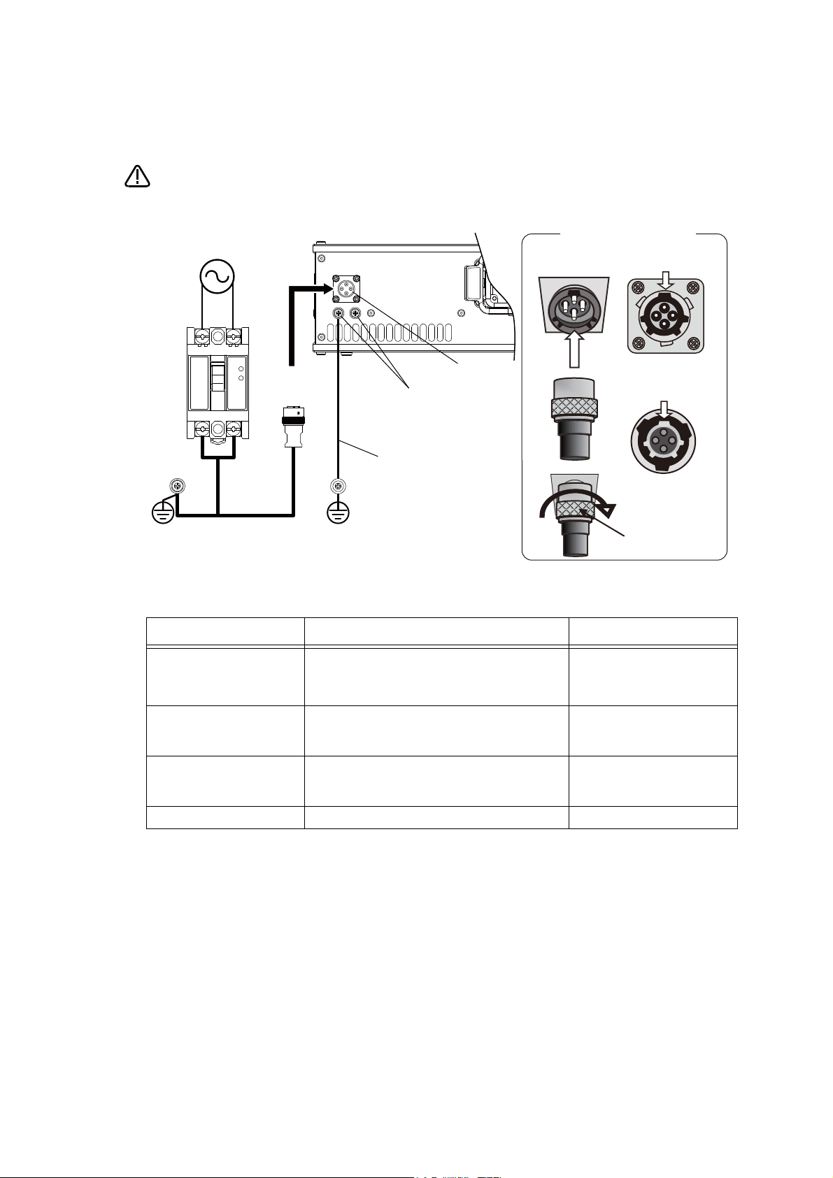
CAUTION
LN
Controller rear
ACIN cable
(attachment)
PE terminal
PE terminal
Primary side
Secondry side
Single phase
AC200V
ACIN connector
PE (protective earth) terminal
M4 screw
Grounding cable
Note 1)
Earth leakage
breaker (NV)
<3>
<1> <2>
ACIN cable connection
ACIN cable
(male)
ACIN socket
(female)
Main key (wide)
Groove for main
key (wide)
Top
Top
Coupling
Note 1) Always use the terminal cover for the earth leakage breaker.
Notes of the basic component are shown.
Please install the earth leakage breaker in the primary side power supply of the
controller because of leakage protection.
1) Prepare the following items.
Part name Specifications Remarks
Earth leakage breaker The following is recommended product. Prepared by customer.
Single phase: NV30FAU-2P-10A-AC100-240V-30mA
(Terminal cover: TCS-05FA2)
Cable for primary power supply
Grounding cable
ACIN cable Terminal: M5, cable length: 3m Supplied with the product.
AWG14 (2mm
AWG14 (2mm
2
) or above
2
) or above
Prepared by customer.
Tightening torque for terminal
fixing screw is 2 ~ 3Nm.
Prepared by customer.
Tightening torque for terminal
fixing screw is 2 ~ 3Nm.
2) Confirm that the primary power matches the specifications.
3) Confirm that the primary power is OFF and that the earth leakage breaker power switch is OFF.
4) Connect the ACIN cable to the breaker.
Connect the power terminals of the ACIN cable to the secondary side terminals of the earth leakage breaker.
Also, ground the FG terminal of the cable.
5) Connect the ACIN cable to the ACIN connector on the rear of the controller.
<1> Face the main key on the ACIN cable plug upwards. (Refer to the "ACIN cable connection" illustration.)
<2> Align the main key of the ACIN cable plug with the grooves on the ACIN connector. Push the plug into the
connector as far as it will go.
The plug may be damaged if it is not correctly aligned with the connector.
<3> Tighten the coupling on the ACIN cable, turning it to the right until it locks.
6) Connect one end of the grounding cable to the PE (protective earth) terminal on the controller and ground the
other end (2-point grounding) in order to comply with the requirements of EN 61800-5-1 for the touch cur
rent of 3.5 mA AC or more.
7) Connect the primary power cable to the primary side terminal of the earth leakage breaker.
-
Page 8
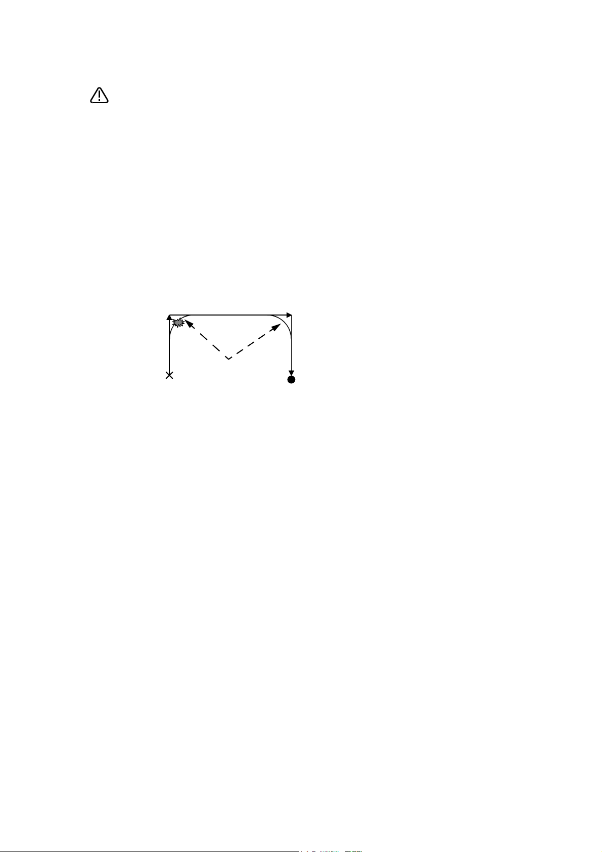
Be careful of interference with peripheral equipment.
CAUTION
Short cut
Arch movement (example)
Especially don't give a shock to the shaft (J3 axis). When you install the
hand, be careful not to knock at the shaft end by the hammer etc. The shaft
may be damaged.
Collision detection function is valid condition for both of automatic and jog operation at shipping in
RH-3FRHR series. However, damage to the ball screw shaft cannot be prevented completely.
Refer to the separate instruction manual "Detailed explanations of functions and operations" for
collision detection function.
Take care also of the following items.
(1)The robot's locus of movement may change with specified speed.
Especially as for the corner section, short cut distance may change. Therefore, when beginning automatic operation, moves at low speed at first, and you should gather speed slowly with
being careful of interference with peripheral equipment.
(2)It can be confirmed whether the specified position exist in the defined area by using the instruc-
tion command "Zone". It can utilize as one of the methods for collision evasion. Refer to the
"detailed description of the instructions manual/function, and operation" of the separate volume
for the details of the instruction command.
Page 9
Revision history
Date of Point Instruction Manual No. Revision Details
2017-04-27 BFP-A3472 ・ First print
2018-03-01 BFP-A3472-A ・ Descriptions of CR800-Q controller were added.
2018-12-25 BFP-A3472-B ・ ”5.6.3 ABS origin method” was corrected.
2019-04-19 BFP-A3472-C ・ Installation dimensions in Fig. 2-6 was corrected.
・ Mechanical stopper position in Fig 3-16 were corrected.
・ Added further explanation of the ACIN cable.
・ Timing belt tension of RH-3FRHR series in Table 5-8 was corrected.
Page 10

*Introduction
・ No part of this manual may be reproduced by any means or in any form, without prior consent from
Mitsubishi.
・ The details of this manual are subject to change without notice.
・ The information contained in this document has been written to be accurate as much as possible.
Please interpret that items not described in this document "cannot be performed." or "alarm may
occur".
Please contact your nearest dealer if you find any doubtful, wrong or skipped point.
・ This specifications is original.
・ Company names and production names in this document are the trademarks or registered trademarks
of their respective owners.
Copyright(C) 2017-2019 MITSUBISHI ELECTRIC CORPORATION
Thank you for purchasing the Mitsubishi industrial robot.
This instruction manual explains the method of unpacking, installation and maintenance and inspection of
the robot arm.
Always read through this manual before starting use to ensure correct usage of the robot.
The information contained in this document has been written to be accurate as much as possible. Please
interpret that items not described in this document "cannot be performed."
And, when maintenance and inspection of the robot, to access the arm and the base section is necessary.
Please prepare the environment which can access the robot with the stepladder etc. in RH-3FRHR.
This document explains for the following robot type.
Robot type
On floor type...........*RH-3FRH series
*RH-6FRH series
*RH-12FRH series
*RH-20FRH series
Hanging type ...........*RH-3FRHR series
Page 11

CONTENTS
Page
1 Before starting use .......................................................................................................................... 1-1
1.1 Using the instruction manuals ................................................................................................... 1-1
1.1.1 The details of each instruction manuals ............................................................................... 1-1
1.1.2 Symbols used in instruction manual .................................................................................... 1-2
1.2 Safety Precautions .................................................................................................................... 1-3
1.2.1 Precautions given in the separate Safety Manual ................................................................ 1-4
2 Unpacking to Installation .............................................................................................................................................................. 2-6
2.1 Confirming the product ......................................................................................................................................................... 2-6
2.2 Installation .................................................................................................................................................................................. 2-7
2.2.1 Unpacking ............................................................................................................................................................................ 2-7
(1) RH-3FRH/6FRH/12FRH/20FRH series ............................................................................................................ 2-7
(2) RH-3FRHR series ....................................................................................................................................................... 2-8
2.2.2 Transportation procedures .......................................................................................................................................... 2-9
(1) RH-3FRH/6FRH series ............................................................................................................................................. 2-9
(2) RH-12FRH/20FRH series ...................................................................................................................................... 2-11
(3) RH-3FRHR series ..................................................................................................................................................... 2-13
2.2.3 Installation procedures ................................................................................................................................................ 2-15
(1) RH-3FRH/6FRH/12FRH/20FRH series .......................................................................................................... 2-15
(2) RH-3FRHR series ..................................................................................................................................................... 2-17
2.2.4 Grounding procedures .................................................................................................................................................. 2-19
(1) Grounding methods ................................................................................................................................................... 2-19
(2) Grounding procedures ............................................................................................................................................. 2-19
2.2.5 Connecting with the controller ................................................................................................................................ 2-20
(1) Connection of robot arm and machine cable ................................................................................................. 2-20
(2) Connection of controller and machine cable ................................................................................................. 2-22
2.2.6 Ethernet Cables (RH-3FRH/6FRH/12FRH/20FRH series) ......................................................................... 2-23
(1) No.2 arm ........................................................................................................................................................................ 2-23
(2) Base area ...................................................................................................................................................................... 2-24
2.2.7 Ethernet Cables (RH-3FRHR series) .................................................................................................................... 2-26
(1) No.2 arm section ........................................................................................................................................................ 2-26
(2) Base area ................................................................................................................
2.2.8 Passing air hoses and cables through the shaft (RH-3FRH/6FRH/12FRH/20FRH series) .......... 2-29
(1) Specifications of internal air hoses and cables ............................................................................................ 2-29
(2) Customer prepared products ............................................................................................................................... 2-29
(3) Installation procedure .............................................................................................................................................. 2-30
(4) RH-3FRH series ........................................................................................................................................................ 2-31
(5) RH-6FRH series ........................................................................................................................................................ 2-32
(6) RH-12FRH/20FRH series ...................................................................................................................................... 2-33
2.2.9 About oil mist specification ....................................................................................................................................... 2-34
(1) Piping for pressurization inside robot arm ...................................................................................................... 2-34
2.2.10 About clean specification ......................................................................................................................................... 2-34
(1) Piping for suction inside robot arm .................................................................................................................... 2-34
(2) Arrangement of the ventilation duct ................................................................................................................. 2-35
2.3 Confirming the operation .................................................................................................................................................... 2-36
2.3.1 Installing the teaching pendant (T/B) ................................................................................................................... 2-37
(1) Turning ON the control power ............................................................................................................................. 2-37
(2) Preparing the T/B ..................................................................................................................................................... 2-38
(3) JOINT jog operation ................................................................................................................................................. 2-42
(4) XYZ jog operation ...................................................................................................................................................... 2-44
(5) TOOL jog operation .................................................................................................................................................. 2-46
(6) 3-axis XYZ jog operation ....................................................................................................................................... 2-48
(7) CYLNDER jog operation ......................................................................................................................................... 2-50
(8) Work jog operation ......................................................................................................... 2-52
2.3.2 Setting the hand parameters .................................................................................................................................... 2-58
...................................................... 2-27
3 Installing the option devices ..................................................................................................................................................... 3-59
i
Page 12

CONTENTS
Page
3.1 Installing the solenoid valve set (RH-3FRH/6FRH/12FRH/20FRH series) ................................................. 3-59
(1) RH-3FRH/6FRH series ........................................................................................................................................... 3-59
(2) RH-12FRH/20FRH series ...................................................................................................................................... 3-61
(3) Hand number and solenoid valve ports (common to floor installation type robot) ....................... 3-62
3.2 Installing the solenoid valve set (RH-3FRHR series) ............................................................................................. 3-63
3.3 Installation of hand tube (RH-3FRHR series) ........................................................................................................... 3-68
3.4 Installing the hand input cable ......................................................................................................................................... 3-72
(1) RH-3FRH/6FRH/12FRH/20FRH series .......................................................................................................... 3-72
(2) RH-3FRHR series ..................................................................................................................................................... 3-73
3.5 Installing the hand output cable ...................................................................................................................................... 3-75
(1) RH-3FRH/6FRH/12FRH/20FRH series .......................................................................................................... 3-75
(2) RH-3FRHR series ..................................................................................................................................................... 3-76
3.6 Changing the operating range .......................................................................................................................................... 3-78
(1) RH-3FRH/6FRH/12FRH/20FRH series .......................................................................................................... 3-78
(2) Operating range changeable angle ..................................................................................................................... 3-78
(3) The change method of the operating range ................................................................................................... 3-79
(4) RH-3FRHR series ..................................................................................................................................................... 3-80
3.6.1 Operating range change of J1 axis ......................................................................................................................... 3-80
3.6.2 Operating range change of J2 axis ......................................................................................................................... 3-82
3.7 Hand internal wiring and piping set (RH-3FRH/6FRH/12FRH/20FRH series) ........................................... 3-84
(1) Installation procedure .............................................................................................................................................. 3-84
(2) RH-3FRH series ........................................................................................................................................................ 3-86
(3) RH-6FRH series ........................................................................................................................................................ 3-87
(4) RH-12FRH/20FRH series ...................................................................................................................................... 3-88
3.8 External Wiring and Piping Box (RH-3FRH/6FRH/12FRH/20FRH series) ................................................... 3-89
3.9 Connector protection when the option devices are installed ............................................................................. 3-91
4 Basic operations ............................................................................................................................................................................ 3-93
5 Maintenance and Inspection ..................................................................................................................................................... 4-94
5.1 Type of inspection and maintenance works ............................................................................................................... 4-94
5.2 Inspection items ..........................................
5.2.1 Daily inspection items .................................................................................................................................................. 4-95
5.2.2 Periodic inspection ........................................................................................................................................................ 4-96
(1) Inspection item ........................................................................................................................................................... 4-96
(2) Schedule ........................................................................................................................................................................ 4-97
5.3 Maintenance and inspection procedures ..................................................................................................................... 4-98
5.3.1 Robot arm structure ..................................................................................................................................................... 4-98
(1) RH-3FRH series ........................................................................................................................................................ 4-98
(2) RH-6FRH/12FRH/20FRH series ........................................................................................................................ 4-99
(3) RH-3FRHR series .................................................................................................................................................. 4-100
5.3.2 Installing/removing the cover ................................................................................................................................ 4-101
(1) RH-3FRH/6FRH/12FRH/20FRH series ....................................................................................................... 4-101
(2) RH-3FRHR series .................................................................................................................................................. 4-103
5.3.3 Packing Replacement Procedure ......................................................................................................................... 4-105
(1) Packing Replacement Instructions .................................................................................................................. 4-105
5.3.4 Inspection replacement of timing belt ................................................................................................................ 4-109
(1) Timing belt replacement period ...................................................................................................................... 4-110
(2) Timing belt tension measurement ................................................................................................................... 4-111
(3) RH-3FRH series: Inspecting the J3 axis timing belt ............................................................................... 4-112
(4) RH-3FRH series: Replacing the J3 axis timing belt ................................................................................ 4-113
(5) RH-6FRH/12FRH/20FRH series: Inspecting the J3 axis timing belt .............................................. 4-116
(6) RH-6FRH/12FRH/20FRH series: Replacing the J3 axis timing belt ................................................ 4-117
(7) RH-3FRH/6FRH/12FRH/20FRH series: Inspecting the J4 axis timing belt ................................. 4-119
(8) RH-3FRHR series: Inspection of J1 axis timing belt .............................................................................. 4-120
(9) RH-3FRHR series: Inspection of J2 axis timing belt .............................................................................. 4-121
........................................................................................................................... 4-95
ii
Page 13

CONTENTS
Page
(10) RH-3FRHR series: Inspection of J3 axis timing belt ............................................................................ 4-122
(11) RH-3FRHR series: Inspection of J4 axis timing belt ............................................................................ 4-123
(12) Timing belt tension .............................................................................................................................................. 4-125
(13) Amount of movement of each axis during the timing belt tension measurement .................... 4-126
5.3.5 Replacing the bellows ................................................................................................................................................ 4-127
(1) RH-3FRH/6FRH/12FRH/20FRH series ....................................................................................................... 4-127
(2) RH-3FRHR series .................................................................................................................................................. 4-129
5.3.6 Lubrication ..................................................................................................................................................................... 4-130
(1) RH-3FRH/6FRH/12FRH/20FRH series ....................................................................................................... 4-130
(2) RH-3FRHR series .................................................................................................................................................. 4-134
5.3.7 Replacing the backup battery ................................................................................................................................ 4-136
(1) Replacing the battery of the robot arm ........................................................................................................ 4-137
5.4 About Overhaul ................................................................................................................................................................... 4-139
5.5 Maintenance parts .............................................................................................................................................................. 4-140
5.6 Resetting the origin ........................................................................................................................................................... 5-142
5.6.1 Setting the origin with the origin data input method ................................................................................... 5-143
(1) Confirming the origin data .................................................................................................................................. 5-143
(2) Selecting the origin setting method ................................................................................................................ 5-144
(3) Inputting the origin data ...................................................................................................................................... 5-145
(4) Installing the cover ................................................................................................................................................ 5-146
5.6.2 Jig method ..................................................................................................................................................................... 4-147
(1) J1 axis origin setting ............................................................................................................................................. 4-148
(2) J2 axis origin setting ............................................................................................................................................. 4-150
(3) J3 and J4 axis origin setting ............................................................................................................................. 4-152
5.6.3 ABS origin method ..................................................................................................................................................... 5-156
(1) RH-3FRH/6FRH/12FRH/20FRH series ....................................................................................................... 5-157
(2) RH-3FRHR series .................................................................................................................................................. 5-158
(3) Origin setting procedure ...................................................................................................................................... 5-159
5.6.4 User origin method ..................................................................................................................................................... 5-160
5.6.5 Recording the origin data ..............................................................................................
(1) Confirming the origin data label ........................................................................................................................ 5-162
(2) Confirming the origin data .................................................................................................................................. 5-162
(3) Recording the origin data .................................................................................................................................... 5-162
(4) Installing the cover ................................................................................................................................................ 5-162
5.7 How to release the brake in an emergency ............................................................................................................. 5-163
6Appendix ............................................................................................................................................................................ Appendix-165
Appendix 1 : Configuration flag .......................................................................................................................... Appendix-165
.......................................... 5-162
iii
Page 14

1Before starting use
1 Before starting use
This chapter explains the details and usage methods of the instruction manuals, the basic terminology and
the safety precautions. Moreover, handling and operation of a teaching pendant (T/B) are described based
on R32TB in instruction manuals. If using other T/B, such as R56TB, refer to a supplied instruction manual
of the T/B.
1.1 Using the instruction manuals
1.1.1 The details of each instruction manuals
The contents and purposes of the documents enclosed with this product are shown below. Use these documents according to the application.
For special specifications, a separate instruction manual describing the special section may be enclosed.
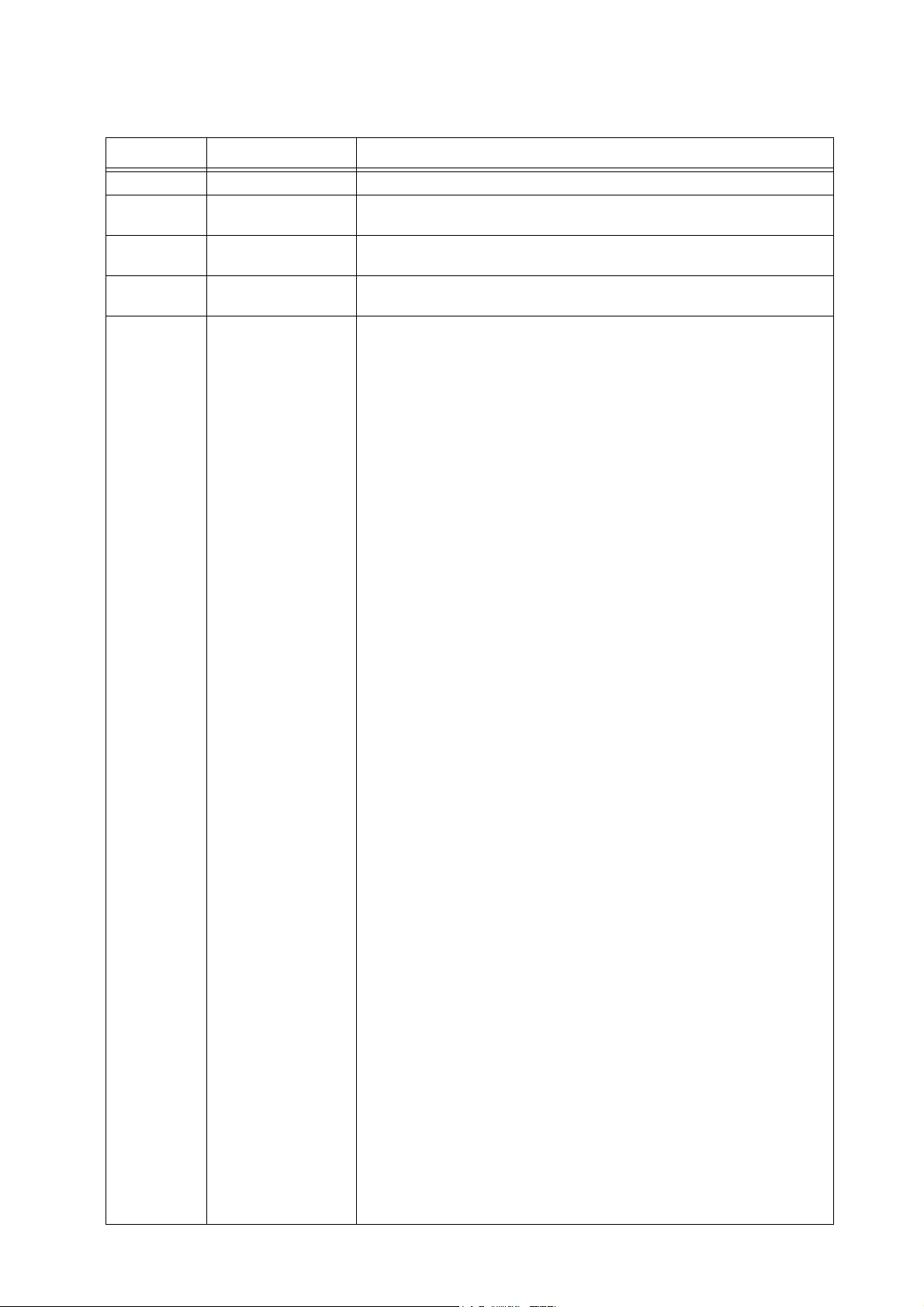
Manual name Description
Safety Manual Explains the common precautions and safety measures to be taken for robot handling, system design
Standard Specifications Explains the product's standard specifications, factory-set special specifications, option configuration
Robot Arm Setup & Maintenance Explains the procedures required to operate the robot arm (unpacking, transportation, installation,
Controller setup, basic operation,
and maintenance
Detailed explanations of functions
and operations
Troubleshooting Explains the causes and remedies to be taken when an error occurs. Explanations are given for each
Additional axis function Explains the specifications, functions and operations of the additional axis control.
Tracking Function Explains the control function and specifications of conveyor tracking.
GOT Direct Connection Extended
Function
iQ Platform Supporting Extended
Function
Ethernet Function Explains the measures to perform communication with personal computers on Ethernet with the
and manufacture to ensure safety of the operators involved with the robot.
and maintenance parts, etc.
Precautions for safety and technology, when incorporating the robot, are also explained.
confirmation of operation), and the maintenance and inspection procedures.
Explains the procedures required to operate the controller (unpacking, transportation, installation,
confirmation of operation), basic operation from creating the program to automatic operation, and the
maintenance and inspection procedures.
Explains details on the functions and operations such as each function and operation, commands used
in the program, connection with the external input/output device, and parameters, etc.
error No.
Explains the detailed description of data configuration of shared memory, monitoring, and operating
procedures about the GOT (standalone type robot).
Explains the detailed description of data configuration of shared memory, monitoring, and operating
procedures about the PLC (iQ Platform compatible type robot).
TCP/IP protocol.
1-1 Using the instruction manuals
Page 15
1Before starting use
DANGER
WARNING
CAUTION
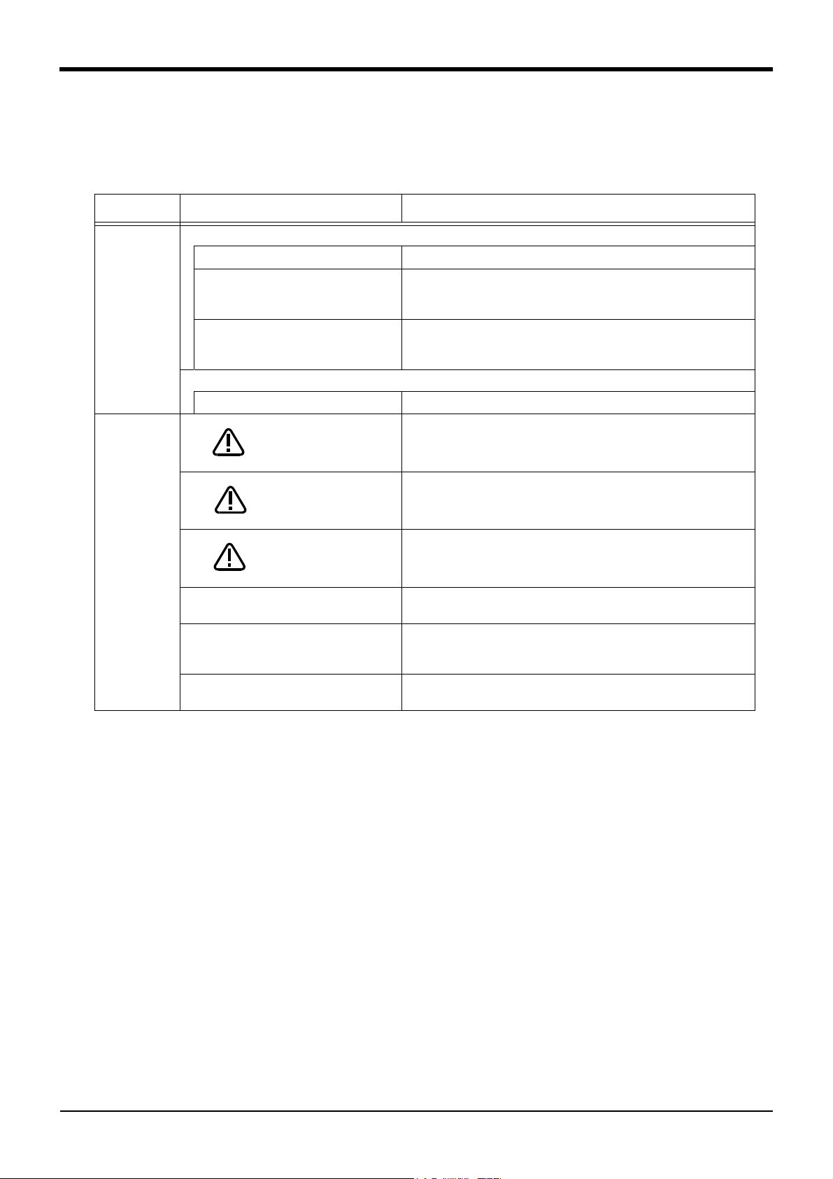
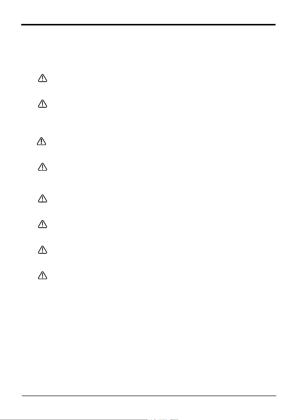
1.1.2 Symbols used in instruction manual
The symbols and expressions shown in Table 1-1 are used throughout this instruction manual. Learn the
meaning of these symbols before reading this instruction manual.
Table 1-1:Symbols in instruction manual
Terminology Item/Symbol Meaning
iQ Platform compatible type
Controller Indicates the controller which controls the robot arm.
Indicates the CPU unit for the robots which installed to the sequencer
The robot CPU unit or robot CPU
Item
The robot CPU system
Standalone type
Controller Indicates the controller which controls the robot arm.
base unit of MELSEC iQ-R/MELSEC-Q series. It is connected with
the controller by the dedicated cable.
Multi-CPU system.
It consists of MELSEC units, such as the sequencer base unit, the
sequencer CPU unit, and the robot CPU unit, etc.
Precaution indicating cases where there is a risk of operator fatality or
serious injury if handling is mistaken. Always observe these precautions to safely use the robot.
Symbol
Precaution indicating cases where the operator could be subject to
fatalities or serious injuries if handling is mistaken. Always observe
these precautions to safely use the robot.
Precaution indicating cases where operator could be subject to injury
or physical damage could occur if handling is mistaken. Always
observe these precautions to safely use the robot.
[JOG]
[RESET] + [EXE]
(A) (B)
T/B This indicates the teaching pendant.
If a word is enclosed in brackets or a box in the text, this refers to a
key on the teaching pendant.
This indicates to press the (B) key while holding down the (A) key.
In this example, the [RESET] key is pressed while holding down the
[EXE] key.
Descriptions in this manual are based on R32TB.
Using the instruction manuals 1-2
Page 16
1Before starting use
CAUTION
CAUTION
WARNING
CAUTION
DANGER
CAUTION
CAUTION
CAUTION
1.2 Safety Precautions
Always read the following precautions and the separate "Safety Manual" before starting use of the robot to
learn the required measures to be taken.
All teaching work must be carried out by an operator who has received special
training. (This also applies to maintenance work with the power source turned ON.)
Enforcement of safety training
For teaching work, prepare a work plan related to the methods and procedures of
operating the robot, and to the measures to be taken when an error occurs or when
restarting. Carry out work following this plan. (This also applies to maintenance
work with the power source turned ON.)
Preparation of work plan
Prepare a device that allows operation to be stopped immediately during teaching
work. (This also applies to maintenance work with the power source turned ON.)
Setting of emergency stop switch
During teaching work, place a sign indicating that teaching work is in progress on
the start switch, etc. (This also applies to maintenance work with the power source
turned ON.)
Indication of teaching work in progress
Provide a fence or enclosure during operation to prevent contact of the operator
and robot.
Installation of safety fence
Establish a set signaling method to the related operators for starting work, and follow this method.
Signaling of operation start
As a principle turn the power OFF during maintenance work. Place a sign indicating
that maintenance work is in progress on the start switch, etc.
Indication of maintenance work in progress
Before starting work, inspect the robot, emergency stop switch and other related
devices, etc., and confirm that there are no errors.
Inspection before starting work
1-3 Safety Precautions
Page 17
1Before starting use
DANGER
CAUTION
CAUTION
CAUTION
CAUTION
CAUTION
CAUTION
WARNING
WARNING
CAUTION
WARNING
CAUTION
CAUTION
CAUTION
CAUTION
WARNING
1.2.1 Precautions given in the separate Safety Manual
The points of the precautions given in the separate "Safety Manual" are given below.
Refer to the actual "Safety Manual" for details.
When automatic operation of the robot is performed using multiple control devices
(GOT, programmable controller, push-button switch), the interlocking of operation
rights of the devices, etc. must be designed by the customer.
Use the robot within the environment given in the specifications. Failure to do so
could lead to a drop or reliability or faults. (Temperature, humidity, atmosphere,
noise environment, etc.)
Transport the robot with the designated transportation posture. Transporting the
robot in a non-designated posture could lead to personal injuries or faults from
dropping.
Always use the robot installed on a secure table. Use in an instable posture could
lead to positional deviation and vibration.
Wire the cable as far away from noise sources as possible. If placed near a noise
source, positional deviation or malfunction could occur.
Do not apply excessive force on the connector or excessively bend the cable.
Failure to observe this could lead to contact defects or wire breakage.
Make sure that the workpiece weight, including the hand, does not exceed the
rated load or tolerable torque. Exceeding these values could lead to alarms or
faults.
Securely install the hand and tool, and securely grasp the workpiece. Failure to
observe this could lead to personal injuries or damage if the object comes off or
flies off during operation.
Securely ground the robot and controller. Failure to observe this could lead to
malfunctioning by noise or to electric shock accidents.
Indicate the operation state during robot operation. Failure to indicate the state
could lead to operators approaching the robot or to incorrect operation.
When carrying out teaching work in the robot's movement range, always secure
the priority right for the robot control. Failure to observe this could lead to personal
injuries or damage if the robot is started with external commands.
Keep the jog speed as low as possible, and always watch the robot. Failure to do
so could lead to interference with the workpiece or peripheral devices.
After editing the program, always confirm the operation with step operation before
starting automatic operation. Failure to do so could lead to interference with
peripheral devices because of programming mistakes, etc.
Make sure that if the safety fence entrance door is opened during automatic operation, the door is locked or that the robot will automatically stop. Failure to do so
could lead to personal injuries.
Never carry out modifications based on personal judgments, or use non-designated maintenance parts.
Failure to observe this could lead to faults or failures.
When the robot arm has to be moved by hand from an external area, do not place
hands or fingers in the openings. Failure to observe this could lead to hands or fingers catching depending on the posture.
Safety Precautions 1-4
Page 18
1Before starting use
CAUTION
CAUTION
CAUTION
DANGER
DANGER
DANGER
DANGER
CAUTION
CAUTION
CAUTION
Do not stop the robot or apply emergency stop by turning the robot controller's
main power OFF.
If the robot controller main power is turned OFF during automatic operation, the
robot accuracy could be adversely affected.
Do not turn off the main power to the robot controller while rewriting the internal
information of the robot controller such as the program or parameters. If the main
power to the robot controller is turned off while in automatic operation or rewriting
the program or parameters, the internal information of the robot controller may be
damaged.
Do not connect the Handy GOT when using the GOT direct connection function of
this product. Failure to observe this may result in property damage or bodily injury
because the Handy GOT can automatically operate the robot regardless of
whether the operation rights are enabled or not.
Do not connect the Handy GOT to a programmable controller when using an iQ
Platform compatible product with the CR800-R/CR800-Q controller. Failure to
observe this may result in property damage or bodily injury because the Handy
GOT can automatically operate the robot regardless of whether the operation rights
are enabled or not.
Do not remove the SSCNET III cable while power is supplied to the multiple CPU
system or the servo amplifier. Do not look directly at light emitted from the tip of
SSCNET III connectors or SSCNET III cables of the Motion CPU or the servo
amplifier. Eye discomfort may be felt if exposed to the light. (Reference: SSCNET
III employs a Class 1 or equivalent light source as specified in JIS C 6802 and
IEC60825-1 (domestic standards in Japan).)
Do not remove the SSCNET III cable while power is supplied to the controller. Do
not look directly at light emitted from the tip of SSCNET III connectors or SSCNET
III cables. Eye discomfort may be felt if exposed to the light. (Reference: SSCNET
III employs a Class 1 or equivalent light source as specified in JIS C 6802 and
IEC60825-1 (domestic standards in Japan).)
Attach the cap to the SSCNET III connector after disconnecting the SSCNET III
cable. If the cap is not attached, dirt or dust may adhere to the connector pins,
resulting in deterioration connector properties, and leading to malfunction.
Make sure there are no mistakes in the wiring. Connecting differently to the way
specified in the manual can result in failures, such as the emergency stop not
being released. In order to prevent from occurring, please be sure to check that all
functions (such as the teaching box emergency stop, customer emergency stop,
and door switch) are working properly after the wiring setup is completed
Use the network equipments (personal computer, USB hub, LAN hub, etc) confirmed by manufacturer. The thing unsuitable for the FA environment (related with
conformity, temperature or noise) exists in the equipments connected to USB.
When using network equipment, measures against the noise, such as measures
against EMI and the addition of the ferrite core, may be necessary. Please fully
confirm the operation by customer. Guarantee and maintenance of the equipment
on the market (usual office automation equipment) cannot be performed.
1-5 Safety Precautions
To maintain the safety of the robot system against unauthorized access from
external devices via the network, take appropriate measures.
To maintain the safety against unauthorized access via the Internet, take measures such as installing a firewall.
Page 19

2Unpacking to Installation
2 Unpacking to Installation
2.1 Confirming the product
The standard configuration of the robot arm, part of the purchased product, is shown in Table 2-1.
Confirm the parts.
Users who have purchased optional products should refer to the separate "Standard Specifications".
Table 2-1 : Standard configuration
No. Part name Type Qty. Remarks
RH-3FRH series
1 Robot arm 1 unit
2 Installation bolts M8 x 40 4 pcs. For robot arm installation
3 Spring washer for installation bolts For M8 4 pcs.
4 Plain washer for installation bolts For M8 4 pcs.
5 Fixing plates 1 set For robot arm transportation
6 Fixing plates installation bolt 1 set
7 Installation bolt for machine-cable M4 x12 4 pcs. To fix to the back of robot arm base
RH-6FRH series
1 Robot arm 1 unit
2 Installation bolts M8 x 40 4 pcs. For robot arm installation
3 Spring washer for installation bolts For M8 4 pcs.
4 Plain washer for installation bolts For M8 4 pcs.
5 Grease nipple WA-610 1 pc.
6 Fixing plates 1 set For robot arm transportation
7 Fixing plates installation bolt 1 set
RH-12FRH/20FRH series
1 Robot arm 1 unit
2 Installation bolts M12×45 4 pcs For robot arm installation
3 Spring washer for installation bolts For M12 4 pcs
4 Plain washer for installation bolts For M12 4 pcs
5 Fixing plates 1 set For robot arm transportation
6 Fixing plates installation bolt 1 set
7 Transporting jig 1 set
8 Transporting jig fixing bolt 1 set
RH-3FRHR series
1 Robot arm 1 unit
2 Installation bolts M8 × 90 4 pcs. For robot arm installation
3 Installation bolts (Spare) M8 × 40 4 pcs.
4 Installation nut M8 4 pcs.
5 Spring washer for installation bolts For M8 8 pcs.
6 Plain washer for installation bolts For M8 8 pcs.
7 Hanging tools (Eye bolt) 1 set To hang the robot arm with the crane.
8 Fixing plate
9 Nats for T slot M5 4 pcs. For fixing the tool wiring etc.
10 T slot cover 1.5m 1 pc. For clean/waterproof specification
1 set
Note1) RH-3FRH/12FRH/20FRH series: Items No. 2 to 4 are contained in the plastic bag of attachment in the robot arm.
RH-6FRH series: Items No. 2 to 5 are contained in the plastic bag of attachment in the robot arm.
RH-3FRHR series: Item No.2 to 6 are contained in the plastic bag of attachment in the robot arm.
No. 7 and 8 are mounted on the robot.
No. 10 is a dustproof cover for T slots in the sides of No.1 arm and No.2 arm of the robot. Please cut and use the T slot
cover to a suitable length.
Fixing plates installation bolt: 5 pcs.
Nuts: 4 pcs.
Confirming the product
2-6
Page 20
2Unpacking to Installation
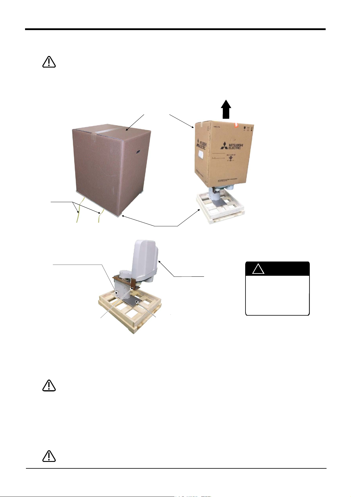
DANGER
②上ブタ
(a)
(b)
(c)
引き抜く
①テープ
固定台
③六角穴付ボルト
(4箇所)
ロボット本体
固定具A
固定具B
!
CAUTION
!
Always unpack the
robot at a flat place.
The robot could tilt
over if unpacked at an
unstable place.
<2> Upper lid
Pull out
<1> Tape
Fixing
board
<3> Hexagon socket
bolts
(Four positions)
Robot arm
Fixing plate B
Fixing plate A
*The grease for preventing rust is applied at the tip of the shaft (J3 axis)
in general-purpose environment robot.
CAUTION
CAUTION
2.2 Installation
Install the robot with a safety fence or enclosure around it. Otherwise, operators may be
injured due to unintended access to the robot.
2.2.1 Unpacking (1) RH-3FRH/6FRH/12FRH/20FRH series
Fig.2-1 : Unpacking the robot arm (RH-3FRH/6FRH/12FRH/20FRH series)
The robot is shipped from the factory in cardboard and plywood frame packing. Always refer to Fig. 2-1 and
unpack the robot. Handle the robot arm according to "2.2.2Transportation procedures".
Always unpack the robot at a flat place. The robot could tilt over if unpacked at an
unstable place.
The unpacking process is shown below.
1) Using a knife, etc., slit the tape <1> fixing the upper lid <2> of the cardboard box. (Fig. 2-1 (a))
2) Pull the upper lid <2> of the cardboard box off with both hands. (Fig. 2-1 (b))
3) Remove the hexagon socket bolts <3> (four positions) which fix the robot. (Fig. 2-1 (c))
The unpacking is completed.
Note) The robot must be transported without removing the fixing plate A and B. Remove after installing.
2-7
Installation
When repackaging the robot in the wooden frame, always use the fixing plate.
Page 21
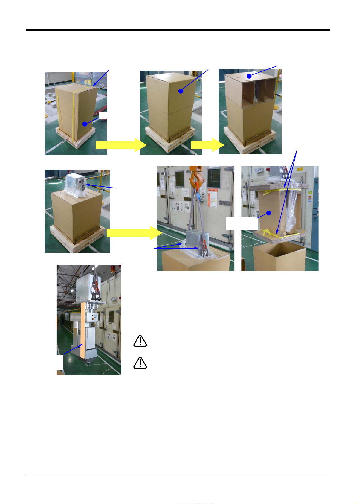
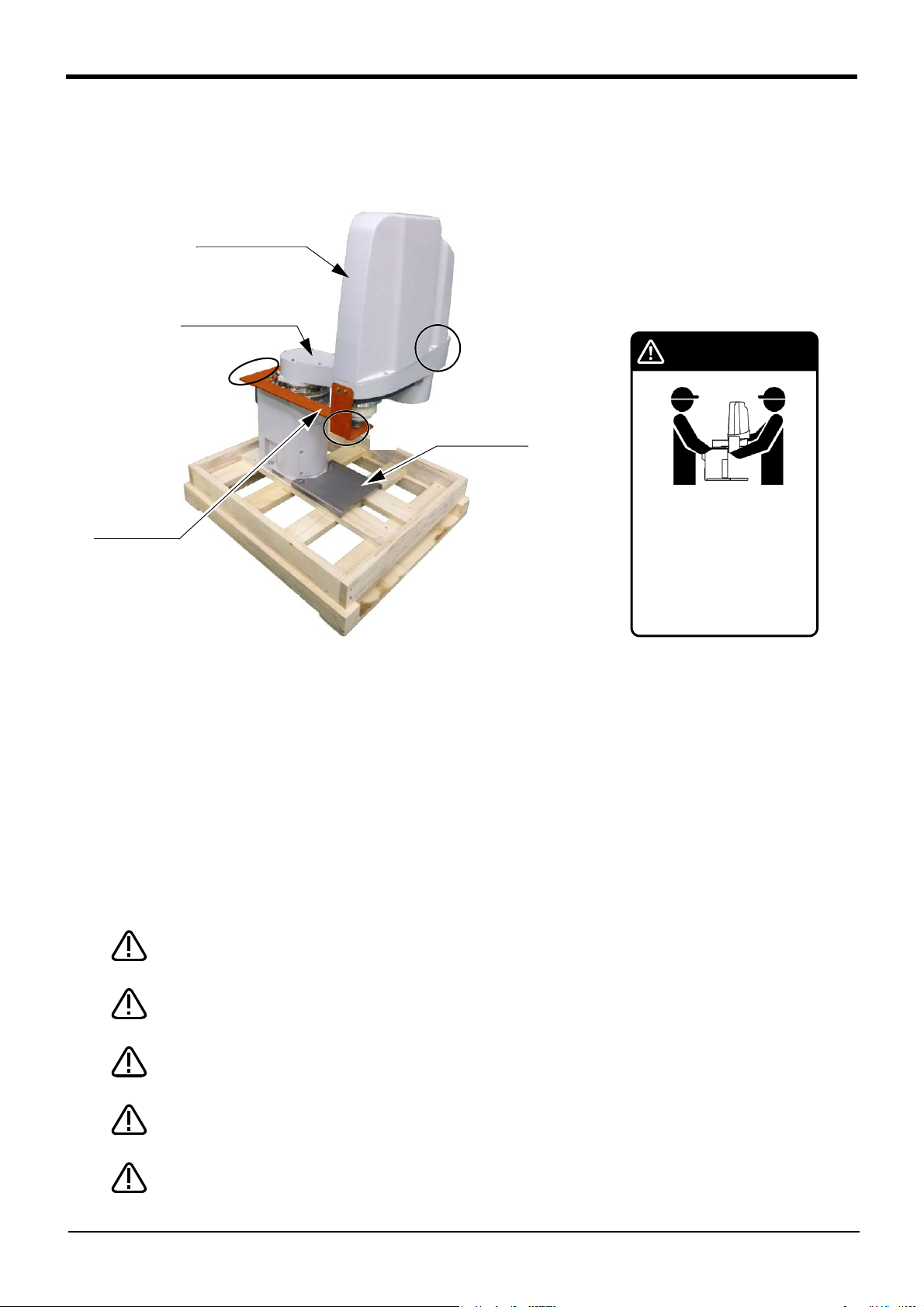
(2) RH-3FRHR series
Unpacking the robot with hoisting.
(Utilize the hanging tools (two places) <4> of the robot arm).
Please unpack near the installation place.
<5> Packing
material
Cut the tape
Hang the hook of the crane.
Completion
Robot-arm
base section
<2> Upper cover
Remove the upper cover. Remove the packing material.
Open the vinyl.
Hoist with crane and remove
the packing material.
<4>hanging tools
(Two places)
<1> Tape
(two)
Packing box
Always unpack the robot at a flat place. The robot
could tilt over if unpacked at an unstable place.
Don't remove fixing plate <7> till installation is
completed. When you pack the robot again, be
sure to install the fixing plate <7>.
CAUTION
CAUTION
<7> Fixing
plate
<3> Packing
material
(Cardboard)
<6> Tape
(two)
*The grease for preventing rust is applied at the tip of the shaft (J3 axis) in general-
purpose environment robot.
2Unpacking to Installation
Fig.2-2 : Unpacking the robot arm (RH-3FRHR series)
The unpacking procedure is shown below.
Unpacking is completd.
1) Cut with scissors etc. the tape <1> of fixing cardboard.
2) Raise and remove upper cover <2>. Remove packing material (cardboard) <3> in the inside.
3) Open the vinyl and confirm the hanging tools (two places) <4>. Hang the hook of the crane here. (Two
places)
4) Hoist with the crane and separate the robot arm together with packing material from the packing box.
5) Cut with scissors etc. tape <6> which fixed packing material <5>, and remove packing material <4>.
Installation
2-8
Page 22
2Unpacking to Installation
注意 CAUTION
VORSICHT
ロボットの運搬は、図の姿勢のように
2人でおこなってください。
The robot must always be
transported by two workers.
Bei einem Transport sollte
der Roboter von 2
Personen an den in der
Abbildung gezeigten Stellen
angehoben werden.
Fixing plate B
No.1 arm
No.2 arm
<1>
<3>
Mass
RH-3FRH35** series: Approx. 31kg
RH-3FRH45** series: Approx. 32kg
RH-3FRH55** series: Approx. 33kg
RH-6FRH35** series: Approx. 39kg
RH-6FRH45** series: Approx. 40kg
RH-6FRH55** series: Approx. 41kg
Fixing plate A
<2>
*The grease for preventing rust is applied
at the tip of the shaft (J3 axis) in gen
-
eral-purpose environment robot.
CAUTION
CAUTION
CAUTION
CAUTION
CAUTION
2.2.2 Transportation procedures (1) RH-3FRH/6FRH series
1) The robot must be transported by two workers with putting the fixing plate A and B. Place the robot on a
cart, etc., and move it to near the installation place. Transporting the robot with the following should be lim
ited to placing the robot on the frame or cart, and to positioning.
2) When transporting the robot arm, one person should hold the fixing plate A of No.2 arm <1> and No.2 arm
<2> and another person should hold the fixing plate A of base <3>. When transporting the robot, do not apply
force to the cover, or apply a strong shock on the robot.
3) Remove the fixtures after installing the robot.
4) Always attach the fixing plate, and follow the above procedures and methods to transport the robot for
secondary transportation, such as when changing the installation position.
If the arm is directly holded without using the specified fixing plate, or if it is holded in the work posture, the
configuration devices could be damaged, and the transportation workers will be subject to risk due to an
inadequate center of gravity position.
Fig.2-3 : Transportation of robot arm (RH-3FRH/6FRH series)
To prevent accidents, do not hold the robot from the left/right sides, or hold covers that
have no grips.
Be careful not to apply force to the shaft section (J3 axis). The shaft may be damaged
and the overload error may occur at the time of movement.
When installing the fixing tool again, place the robot in the posture where each axis
shows the values listed in Table 2-2.
The robot should keep vertical. (not be horizontal)
It becomes the cause of the grease leakage or the trouble.
-
2-9
Installation
The ventilation duct is attached to the clean specification robot’s base section rear.
Please handle with care when transporting or installing the robot arm.
Page 23
CAUTION
2Unpacking to Installation
If it is difficult to follow the transportation procedure shown in this section, take
countermeasures not to allow the joints of the robot arm freely move by fixing the robot
arm in such a way as to take advantage of the screw holes for fixing plates or the like.
Otherwise, applying an excessive power on the joints by external forces may cause a
malfunction.
Do not apply an excessive load to the robot arm while fixing it. Otherwise, the robot arm
may be damaged.
Table 2-2 : Transportation posture (RH-3FRH/6FRH series)
Axis RH-3FRH35** RH-3FRH45** RH-3FRH55** RH-6FRH35** RH-6FRH45** RH-6FRH55**
J 1 49.5 deg. 25 deg. 17 deg. 57.5 deg. 28 deg. 19 deg.
J 2 -139.5 deg. -115 deg. -107 deg. -147.5 deg. -118 deg. -109 deg.
J 3 290.4mm 290.4mm
J4 Not fixed Not fixed
Installation
2-10
Page 24
2Unpacking to Installation
Mass
RH-12FRH55** series: Approx. 65kg
RH-12FRH70** series: Approx. 67kg
RH-12FRH85** series: Approx. 69kg
RH-20FRH85** series: Approx. 75kg
RH-20FRH100** series: Approx. 77kg
Self-supporting plate
Base
Transport
-
ing jig
Fixing plate
Eye bolt
No.1 arm
Wire hook
Wire
Note 1)
No.2 arm
*The grease for preventing rust is applied at the
tip of the shaft (J3 axis) in general-purpose
environment robot.
Note 1) Use wires that are 1300 mm or more.
CAUTION
CAUTION
CAUTION
CAUTION
CAUTION
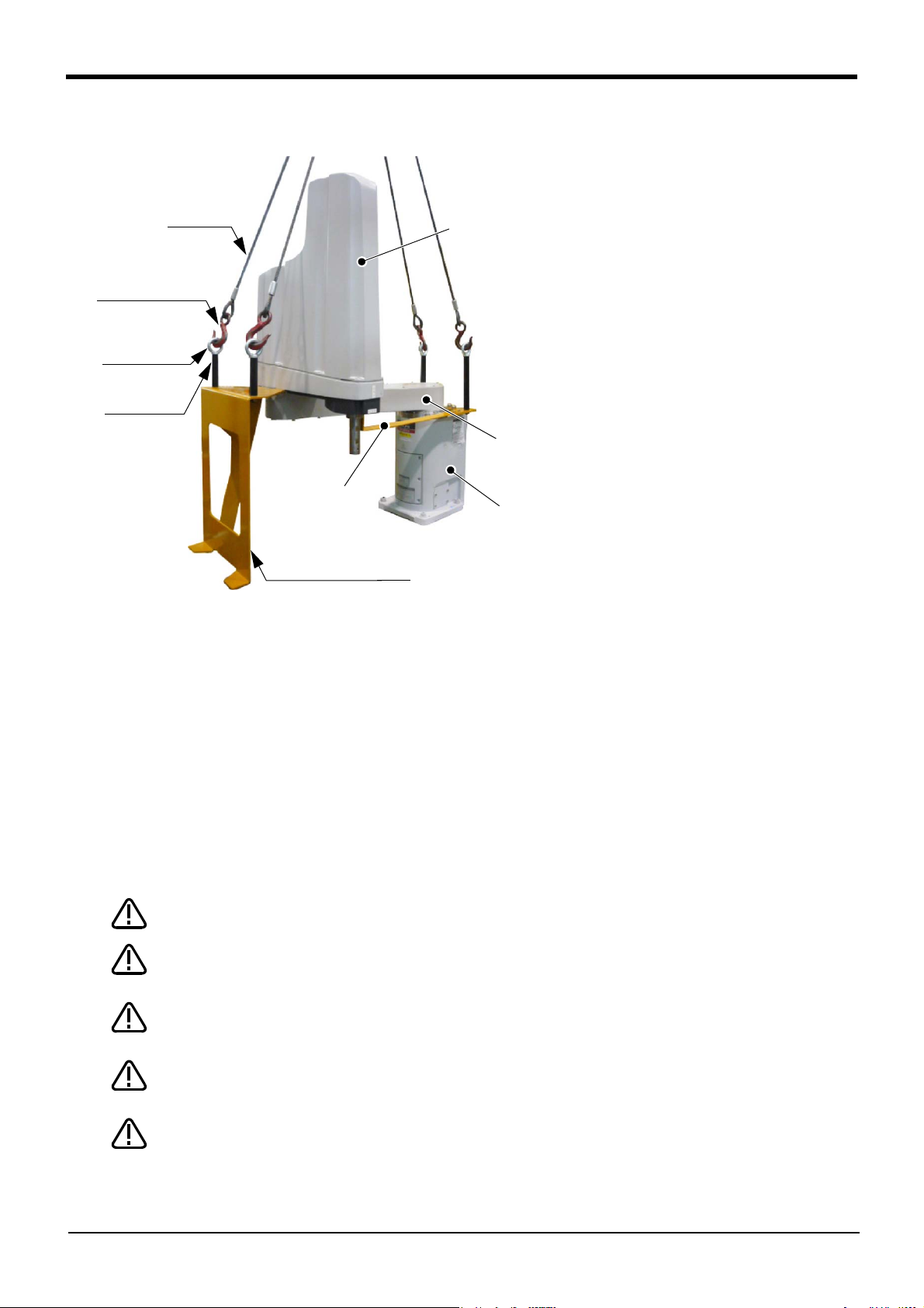
(2) RH-12FRH/20FRH series
Fig.2-4 : Transportation of robot arm (RH-12FRH/20FRH series)
1) Hook the wires to each of the four eyebolts attached to the transporting jig. (Make sure the bolts are
securely hooked.)
2) Lift with a crane to transport the robot to the designated location.
3) At this time, make sure that the wires, etc., do not interfere with the robot arm or the covers. Always place
the cloth, etc., at interfering places.
4) Be careful not to subject the robot to physical shock during transport.
5) After installing the robot (refer to Page 15, "2.2.3 Installation procedures"), remove the wires, the wire
hooks (the robot will stand by itself as shown in Fig. 2-4), the self-supporting plate, transporting jig and fix
ing plate.
6) Always attach the self-supporting plate, fixing plate, and transporting jig, and follow the above procedures
and methods to transport the robot for secondary transportation, such as when changing the installation
position.
If the arm is directly suspended without using the specified transporting jig, or if it is suspended in the work
posture, the configuration devices could be damaged, and the transportation workers will be subject to risk
due to an inadequate center of gravity position.
When transporting a robot, always attach four wires.
To reattach the fixing plate again, set the axes of the robot to the positions according to
Table 2-3.
The robot should keep vertical. (not be horizontal)
It becomes the cause of the grease leakage or the trouble.
-
2-11
Installation
The ventilation duct is attached to the clean specification robot’s base section rear.
Please handle with care when transporting or installing the robot arm.
When the robot is not installed, the self-supporting plate must be attached to the robot.
The robot could tilt over, if the self-supporting plate is not attached to the robot.
Page 25
CAUTION
2Unpacking to Installation
If it is difficult to follow the transportation procedure shown in this section, take
countermeasures not to allow the joints of the robot arm freely move by fixing the robot
arm in such a way as to take advantage of the screw holes for fixing plates or the like.
Otherwise, applying an excessive power on the joints by external forces may cause a
malfunction.
Do not apply an excessive load to the robot arm while fixing it. Otherwise, the robot arm
may be damaged.
Table 2-3 : Transportation posture (RH-12FRH/20FRH series)
Axis
J1 -37.5° -21.4° -15.1° -21.0°
J2 127.5° 111.4° 105.1° 111.0°
Note1)
J3
J4 Not fixed
RH-12FRH55** RH-12FRH70** RH-12FRH85** RH-20FRH85** RH-20FRH100**
340mm
Note1) The bottom surface of the shaft will interfere with the floor if the J3 axis is lowered down to the upper
mechanical stopper. Position the axes as indicated when transporting the robot.
Installation
2-12
Page 26
2Unpacking to Installation
Mass
RH-3FRHR3515: Approx. 24kg
RH-3FRHR3512C/3512W: Approx. 28kg
Note)
Note) Be cautious of interference
at the end of the shaft.
Hoisting
Transport
<8> Installation stage
Install
<4> Transporting jig (two places)
<9> Installation bolt, Nut
(four places)
<7> Fixing
plate
*The grease for preventing rust is applied at the tip
of the shaft (J3 axis) in general-purpose environ
-
ment robot.
CAUTION
CAUTION
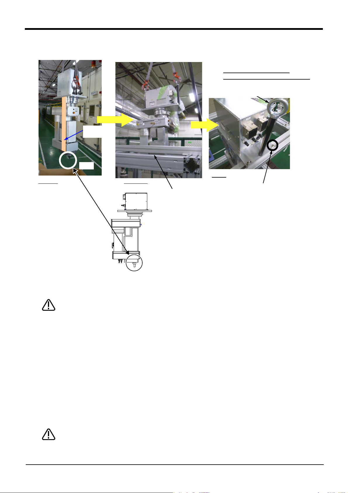
(3) RH-3FRHR series
Fig.2-5 : Transportation of robot arm (RH-3FRHR series)
The transportation procedure is shown below. Transport the robot with careful of safety, referring to Fig. 2-5.
Transport by using the crane with fixing plate <7> still being installed is necessary.
Transport carefully so that the robot may not tilt by using two wires. Take care suffi
ciently not to give the interference and the shock with the installation stage etc.,
1) Transport the robot by the crane from the condition which unpacking completed to the fixing position of
installation stage <8>.
2) Fixing the robot by four installation bolts <9> (attached) certainly to installation stage <8>.
3) Remove transporting jigs (two places) <4> after installation. Loosen the screw (M5 x 4, M4x1) fixing the fix
ing plate <7>, and remove the fixing plate <7>. Also remove the nut for T slots. Fixing plate <7>, and fixing
screws and transporting jigs <4> are needed at secondary transportation. Please keep them with care.
4) Always attach the fixing plate and transporting jig, and follow the above procedures and methods to
transport the robot for secondary transportation, such as when changing the installation position.
If the arm is directly suspended without using the specified transporting jig, or if it is suspended in the work
posture, the configuration devices could be damaged, and the transportation workers will be subject to risk
due to an inadequate center of gravity position.
Transportation is complete above.
To reattach the fixing plate again, set the axes of the robot to the positions according to
Table 2-4.
-
-
2-13
Installation
Page 27
CAUTION
If it is difficult to follow the transportation procedure shown in this section, take
countermeasures not to allow the joints of the robot arm freely move by fixing the robot
arm in such a way as to take advantage of the screw holes for fixing plates or the like.
Otherwise, applying an excessive power on the joints by external forces may cause a
malfunction.
Do not apply an excessive load to the robot arm while fixing it. Otherwise, the robot arm
may be damaged.
Table 2-4 : Transportation posture (RH-3FRHR series)
Axis
J1 0 deg.
J2 0 deg.
Note1)
J3
J4 Not fixed
RH-3FRHR3515 RH-3FRHR3512C/3512W
-569.5mm (Upper end) -599.5mm (Upper end)
Note1) Because if the J3 axis is lowered the shaft juts danger, be sure to specified
posture at transport.
2Unpacking to Installation
Installation
2-14
Page 28
2Unpacking to Installation
(4箇所)
バネ座金
平座金
20
4-M8×40
F
H
F
V
F
H
F
H
F
H
M
L
M
L
F
V
M
T
(Four positions)
Spring washer
Plain washer
<Detail of installation dimension>
(Base section of a robot arm)
RH-3FRH/6FRH series
RH-12FRH/20FRH series
4-M8x40 (RH-3FRH/6FRH series)
4-M12x45 (RH-12FRH/20FRH series)
2.2.3 Installation procedures
The installation procedure of the robot arm is shown below.
(1) RH-3FRH/6FRH/12FRH/20FRH series
㻔㼒㼛㼞㻌䃥㻤㻌㼜㼛㼟㼕㼠㼕㼛㼚㼕㼚㼓㻌㼜㼕㼚㼟㻕
㻞㻙䃥㻢㻌㼔㼛㼘㼑㼟
㻠㻙䃥㻥㻌㼕㼚㼟㼠㼍㼘㼘㼍㼠㼕㼛㼚㻌㼔㼛㼘㼑㼟
㻔㻵㼚㼟㼠㼍㼘㼘㼍㼠㼕㼛㼚㻌
㼞㼑㼒㼑㼞㼑㼚㼏㼑㻌㼟㼡㼞㼒㼍㼏㼑㻕
㻾㼦㻞㻡
㻥㻞
㻝㻤㻞
Fig.2-6 : Installation dimensions (RH-3FRH/6FRH/12FRH/20FRH series)
1) The robot installation surface has been machine finished. Use the installation holes (RH-3FRH/6FRH: 4-φ9
holes, RH-12FRH/20FRH: 4-φ16 holes) opened at the four corners of the base, and securely fix the robot
with the enclosed installation bolts (hexagon socket bolts).
2) Install the robot on a level surface.
3) It is recommended that the surface roughness of the table onto which the robot is to be installed by Rz25 or
more. If the installation surface is rough, the contact with the table will be poor, and positional deviation
could occur when the robot moves.
4) When installing, use a common table to prevent the position of the devices and jigs subject to robot work
from deviating.
5) The installation surface must have sufficient strength to withstand the arm reaction during operation, and
resistance against deformation and vibration caused by the static (dynamic) load of the robot arm and
peripheral devices, etc.
6) After installing the robot, remove the self-supporting plate, hanging jig, and fixing plate.
㻝㻤㻜
㻔㻵㼚㼟㼠㼍㼘㼘㼍㼠㼕㼛㼚㻌
㼞㼑㼒㼑㼞㼑㼚㼏㼑㻌㼟㼡㼞㼒㼍㼏㼑㻕
㻾㼦㻞㻡
㻝㻡㻜
㻝㻢㻜
㻞㻝㻞
㻥㻞
㻝㻞㻜㻥㻜
㻝㻡㻜
㻢㻜
㻔㼒㼛㼞㻌䃥㻤㻌㼜㼛㼟㼕㼠㼕㼛㼚㼕㼚㼓㻌㼜㼕㼚㼟㻕
㻠㻙䃥㻝㻢㻌㼕㼚㼟㼠㼍㼘㼘㼍㼠㼕㼛㼚㻌㼔㼛㼘㼑㼟
㻔㻵㼚㼟㼠㼍㼘㼘㼍㼠㼕㼛㼚㻌
㼞㼑㼒㼑㼞㼑㼚㼏㼑㻌㼟㼡㼞㼒㼍㼏㼑㻕
㻝㻣㻠
㻞㻙䃥㻢㻌㼔㼛㼘㼑㼟
㻝㻞㻞
㻞㻠㻞
㻾㼦㻞㻡
㻞㻠㻜
㻔㻵㼚㼟㼠㼍㼘㼘㼍㼠㼕㼛㼚㻌
㼞㼑㼒㼑㼞㼑㼚㼏㼑㻌㼟㼡㼞㼒㼍㼏㼑㻕
㻾㼦㻞㻡
㻞㻜㻜
㻞㻞㻜
㻝㻞㻞
㻝㻞㻜
㻞㻤㻜
㻔㻝㻡㻤㻕
㻞㻜㻜
㻤㻜
㻝㻤㻜
2-15
Installation
Page 29
CAUTION
2Unpacking to Installation
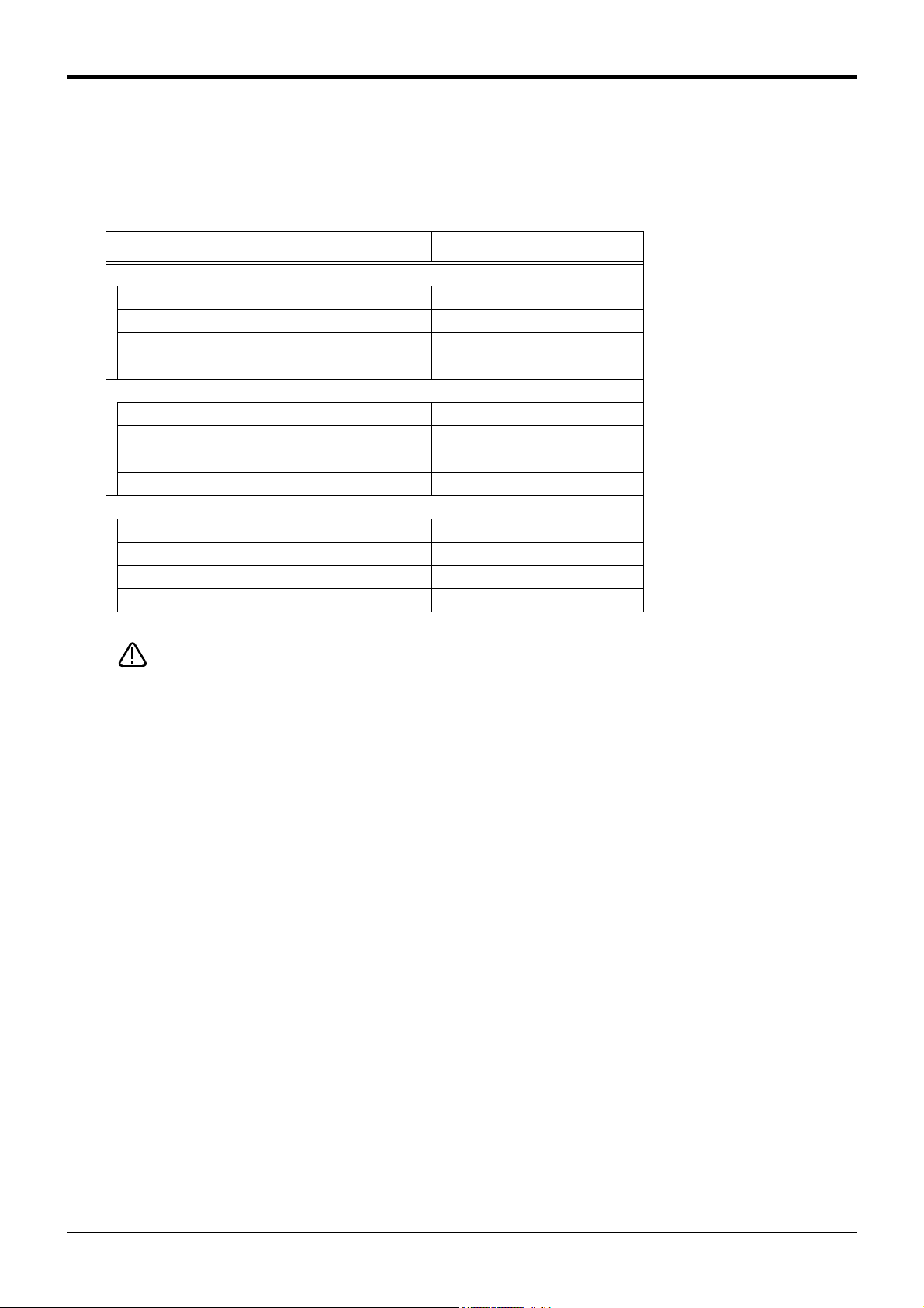
7) If you operate the robot at a high speed, reaction forces are applied to the installation stand by the robot's
operation. Make sure that the installation stand on which the robot is placed has sufficient strength and
rigidity. Table 2-5 shows the maximum reaction force (design values) that may be applied to an installation
stand. Please use these values as reference when designing the installation stand.
Table 2-5 : Magnitude of each reaction force
Item
RH-3FRH series
Tilt moment : M
Torsional moment : M
L
T
Horizontal direction translation force : F
Vertical direction translation force : F
RH-6FRH series
Tilt moment : M
Torsional moment : M
L
T
V
Horizontal direction translation force : F
Vertical direction translation force : F
RH-12FRH/20FRH series
Tilt moment : M
Torsional moment : M
L
T
V
Horizontal direction translation force : F
Vertical direction translation force : F
V
H
H
H
Unit Value
N ・ m 240
N ・ m 255
N 810
N 380
N ・ m 1,640
N ・ m 710
N 1,653
N 2,318
N ・ m 3,190
N ・ m 1,840
N 2,240
N 2,500
When installing the robot, secure enough space for connection of the machine cable and
replacement of the backup battery in front of or behind the robot base. And don't install
the robot arm in the position where direct rays or the heat of lighting hits. The skin tem
perature of the robot arm may rise, and the error may occur.
-
Installation
2-16
Page 30

2Unpacking to Installation
㻾㼦㻞㻡
㻾㼦㻞㻡
㻟㻢㻜
㻟㻠㻜
㻝㻤㻜㻛㻞㻜㻜
㻝㻢㻜
㻔㻵㼚㼟㼠㼍㼘㼘㼍㼠㼕㼛㼚㻌㼞㼑㼒㼑㼞㼑㼚㼏㼑㻕
㻔㻵㼚㼟㼠㼍㼘㼘㼍㼠㼕㼛㼚㻌
㼞㼑㼒㼑㼞㼑㼚㼏㼑㻕
㻠㻙䃥㻥
㼕㼚㼟㼠㼍㼘㼘㼍㼠㼕㼛㼚㻌㼔㼛㼘㼑
㻹㼍㼕㼚㼠㼑㼚㼍㼚㼏㼑㻌㼟㼜㼍㼏㼑
㻞㻙㻹㻝㻞㻌㼔㼛㼘㼑㻌㼒㼛㼞㻌㼔㼍㼚㼓㼕㼚㼓㻌㼠㼛㼛㼘㼟
㻠㻙㻹㻤㻌㼔㼛㼘㼑㻌㼒㼛㼞㻌㼖㼍㼏㼗㻙㼡㼜
㻵㼚㼟㼠㼍㼘㼘㼍㼠㼕㼛㼚㻌㼟㼠㼍㼓㼑
㻔㼑㼤㼍㼙㼜㼘㼑㻕
㻺㼛㼠㼑㻌㻝㻕
㻺㼛㼠㼑㻌㻞㻕
㻔㻤㻜㻕
㻟㻟㻢
㻟㻝㻜
㻞㻟㻜
㻟㻜㻜㻡㻜㻜
㻤㻞
㻹㼍㼕㼚㼠㼑㼚㼍㼚㼏㼑㻌㼟㼜㼍㼏㼑
FV
MT
FH
ML
FH
ML
FH
FH
FV
Note1) General environment type:
180mm
Clean/waterproof specification:
200mm
Note2) The interference of installation bolt
and No.1 arm may occur depending on
the size of installation stage. Take care
against interference of installation bolt,
such as inserting the installation bolt
from the bottom.
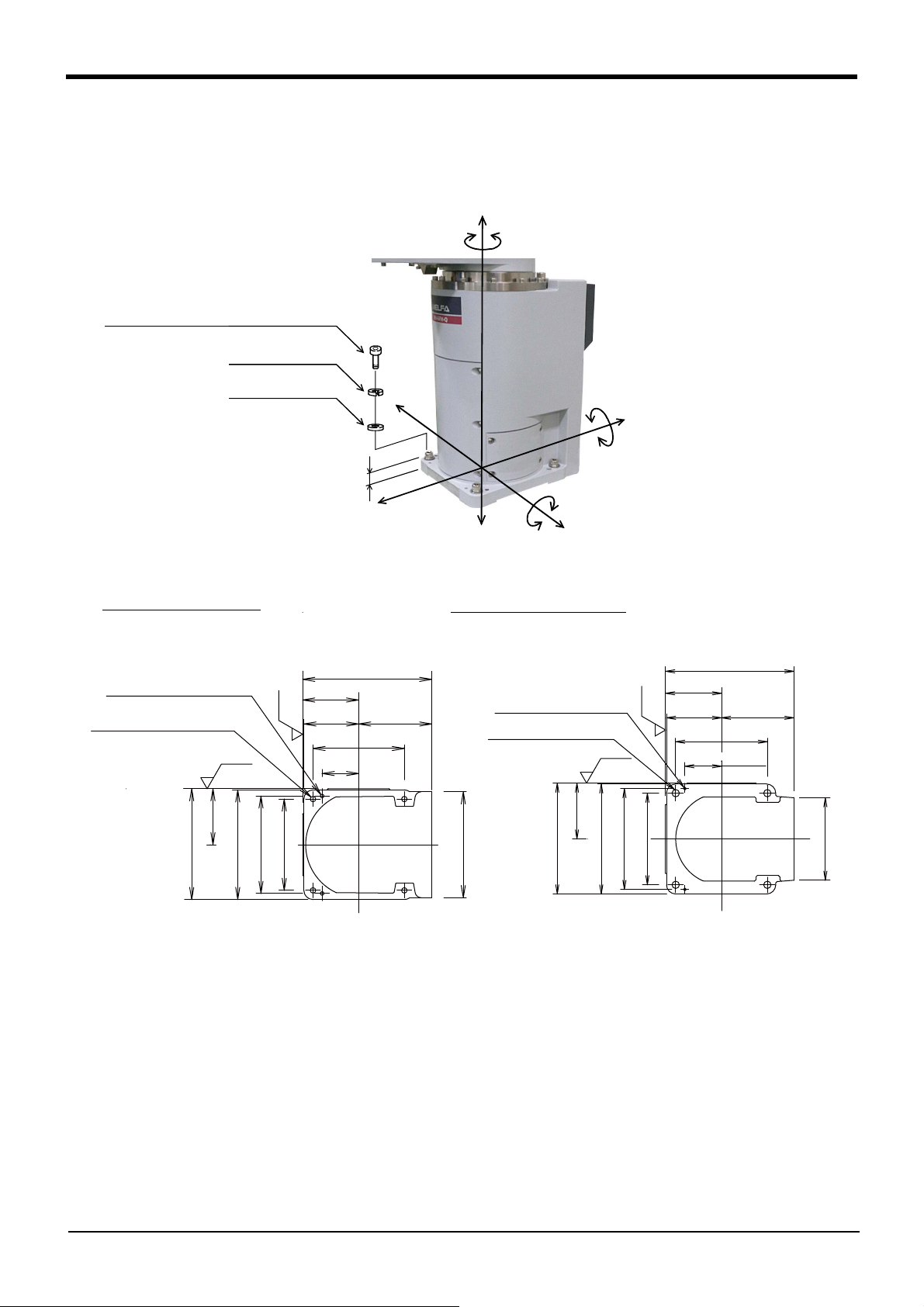
(2) RH-3FRHR series
2-17
Fig.2-7 : Installation dimensions (RH-3FRHR series)
1) The robot installation surface has been machine finished. Use the installation holes (4-φ9) opened at the
four corners of the base, and securely fix the robot with the enclosed installation bolts (hexagon socket
bolts).
2) Install the robot on a level surface.
3) It is recommended that the surface roughness of the table onto which the robot is to be installed by Rz25 or
more. If the installation surface is rough, the contact with the table will be poor, and positional deviation
could occur when the robot moves.
4) When installing, use a common table to prevent the position of the devices and jigs subject to robot work
from deviating.
5) The installation surface must have sufficient strength to withstand the arm reaction during operation, and
resistance against deformation and vibration caused by the static (dynamic) load of the robot arm and
peripheral devices, etc.
6) If you operate the robot at a high speed, reaction forces are applied to the installation stand by the robot's
operation. Make sure that the installation stand on which the robot is placed has sufficient strength and
rigidity. Table 2-5 shows the maximum reaction force (design values) that may be applied to an installation
stand. Please use these values as reference when designing the installation stand.
Installation
Page 31

CAUTION
2Unpacking to Installation
7) If you use a clean specification or a waterproof specification robot, always install T-slot cover (attachment)
after installing the robot.
Table 2-6 : Magnitude of each reaction force
Item
Unit Value
Tilt moment
Torsional moment : M
: M
L
T
Horizontal direction translation force : F
Vertical direction translation force : F
V
Secure the maintenance space necessary at rear for connection of the machine cable
and at side for replacement of the backup battery. And don't install the robot arm in the
position where direct rays or the heat of lighting hits. The skin temperature of the robot
arm may rise, and the error may occur.
N・m 380
N・m 410
H
N920
N570
Installation
2-18
Page 32

2Unpacking to Installation
㻾㼛㼎㼛㼠㻌㼍㼞㼙
㻔㼍㻕㻌㻰㼑㼐㼕㼏㼍㼠㼑㼐㻌㼓㼞㼛㼡㼚㼐㼕㼚㼓
㼇㻻㼜㼠㼕㼙㼡㼙㼉
㻔㼎㻕㻌㻿㼔㼍㼞㼑㼐㻌㼓㼞㼛㼡㼚㼐㼕㼚㼓
㻌㼇㻳㼛㼛㼐㼉
㻔㼏㻕㻌㻯㼛㼙㼙㼛㼚㻌㼓㼞㼛㼡㼚㼐㼕㼚㼓
㼇㻺㼛㼠㻌㼍㼘㼘㼛㼣㼑㼐㼉
㻯㼛㼚㼠㼞㼛㼘㼘㼑㼞
㼍㼚㼐
㼜㼑㼞㼟㼛㼚㼍㼘
㼏㼛㼙㼜㼡㼠㼑㼞
㻾㼛㼎㼛㼠㻌㼍㼞㼙
㻯㼛㼚㼠㼞㼛㼘㼘㼑㼞
㼍㼚㼐
㼜㼑㼞㼟㼛㼚㼍㼘
㼏㼛㼙㼜㼡㼠㼑㼞
㻾㼛㼎㼛㼠㻌㼍㼞㼙
㻯㼛㼚㼠㼞㼛㼘㼘㼑㼞
㼍㼚㼐
㼜㼑㼞㼟㼛㼚㼍㼘
㼏㼛㼙㼜㼡㼠㼑㼞
㻭
㻭
Plain washer
Spring washer
M4x10
Robot grounding cable
(Prepared by customer)
Robot grounding cable
(Prepared by customer)
Plain washer
Spring washer
M4x10
<RH-3FRH/6FRH/12FRH/20FRH series> <RH-3FRHR series>
2.2.4 Grounding procedures (1) Grounding methods
1) There are three grounding methods as shown in Fig. 2-8, but the dedicated grounding (Fig. 2-8 (a)) should be
used for the robot arm and controller when possible. (Refer to the separate " Controller Setup, Basic
Operation and Maintenance" for details on the controller grounding.)
2) Use Class D grounding (grounding resistance 100Ω or less). Dedicated grounding separated from the other
devices should be used.
3) Use a AWG#11(4.2mm
close to the robot arm and controller as possible, and the length of the grounding wire should be short.
2
) or more stranded wire for the grounding wire. The grounding point should be as
(2) Grounding procedures
Fig.2-8 : Grounding methods
1) Prepare the grounding cable (AWG#11(4.2mm2) or more) and robot side installation screw and washer.
2) If there is rust or paint on the grounding screw section (A), remove it with a file, etc.
3) Connect the grounding cable to the grounding screw section.
Fig.2-9 : Connecting the grounding cable
2-19
Installation
Page 33

2.2.5 Connecting with the controller
Controller rear
Robot arm (Base section rear)
RH-3FRH/6FRH/
12FRH/20FRH series
RH-3FRHR series
㻿㼏㼞㼑㼣
㻹㼍㼏㼔㼕㼚㼑㻌㼏㼍㼎㼘㼑㻌
㼞㼛㼎㼛㼠㻌㼍㼞㼙㻌㼟㼕㼐㼑㻌
㼏㼛㼚㼚㼑㼏㼠㼛㼞
㻾㼛㼎㼛㼠㻌㼍㼞㼙㻌
㻯㻺㻝㻌㼏㼛㼚㼚㼑㼏㼠㼛㼞
CAUTION
Be careful not to get your hand
pinched.
2Unpacking to Installation
Fig.2-10 : Connecting the machine cables
Carry out the following procedure after installing the controller referring to the separate "Controller Setup, Basic
Operation and Maintenance" manual.
(1) Connection of robot arm and machine cable
1) Make sure that the power of the controller is turned OFF.
2) Connect the machine cable to CN1 connector on the robot
arm.
Note) RH-6FRH series is shown. The same connection
method is also applicable to other models with the
same-shaped connector.
Insert the connector until the connector edge is aligned
with the CONBOX surface and tighten two bolts.
(Screw fixing torque: 3.6 to 4.4 Nm)
Connecting the machine cable is completed.
Installation
2-20
Page 34

2Unpacking to Installation
CAUTION
CAUTION
CAUTION
CAUTION
CAUTION
When installing or removing the connector, to the connector of the other party in
parallel, install or remove.
If load strong against one side is applied, the connector pin may be damaged and it
may not be connected securely.
The machine cable connectors are dedicated for the controller side and robot arm
side, so take special care when connecting.
If connected incorrectly, the connector pins could bend or break. Thus, even if
connected correctly, the robot will not operate correctly, creating a dangerous
situation.
Take special care to the leading of the connection cable. If the cable is pulled with
force or bent excessively, wires could break or the connector could be damaged.
Connect the machine cable at the place without the effect of the dust or oil mist.
Please keep the dust and oil mist from being applied to of the robot arm connector
section, in the condition that the machine cable is removed. Since it becomes the
cause of failure.
Before disconnecting the machine cable, wipe off dust and oil mist around the con
nector.
-
Please be careful not to catch the hand at installation and removal.
To disconnect the machine cable, hold the connector part and pull out the cable.
Pulling the cable part may cause the cable to come off or break.
2-21
Installation
Page 35

㻸㼍㼠㼏㼔
㻯㻺㻝㻌㼏㼛㼚㼚㼑㼏㼠㼛㼞
㻹㼍㼏㼔㼕㼚㼑㻌㼏㼍㼎㼘㼑㻌
㼏㼛㼚㼠㼞㼛㼘㼘㼑㼞㻌㼟㼕㼐㼑㻌㼏㼛㼚㼚㼑㼏㼠㼛㼞
CAUTION
CAUTION
CAUTION
CAUTION
CAUTION
CAUTION
2Unpacking to Installation
(2) Connection of controller and machine cable
1) Make sure that the power of the controller is turned OFF.
2) Connect the controller side connector of the machine cable to CN1 connector on the rear side of the con
troller.
3) To fix the inserted connector, close the latches of the CN1 connector.
-
Connecting the machine cable is completed.
When connecting and disconnecting the connector, be careful not to get your hand
pinched.
When installing or removing the connector, to the connector of the other party in
parallel, install or remove.
If load strong against one side is applied, the connector pin may be damaged and it
may not be connected securely.
To disconnect the cable, open the latches, hold the connector part, and pull out the
cable. Pulling the cable part may cause the cable to come off or break.
The machine cable connectors are dedicated for the controller side and robot arm
side, so take special care when connecting.
If connected incorrectly, the connector pins could bend or break. Thus, even if
connected correctly, the robot will not operate correctly, creating a dangerous
situation.
Take special care to the leading of the connection cable. If the cable is pulled with
force or bent excessively, wires could break or the connector could be damaged.
Connect the machine cable at the place without the effect of the dust or oil mist.
Please keep the dust and oil mist from being applied to of the robot arm connector
section, in the condition that the machine cable is removed. Since it becomes the
cause of failure.
Installation
2-22
Page 36

2Unpacking to Installation
<a> Ethernet cable: 4 pairs, totaling 8 lines, of AWG#26(0.13mm2)
Note) When using by passing through the shaft, please use the optional
hand internal wiring and piping set to prevent the cable disconnection.
When using as spare wiring
When using as the Ethernet cable
LAN connector
Customer prepared Robot side
Customer prepared Robot side
Connect the customer's connector
Cut the LAN connectors
Shaft
Note) Although the figure is RH-6FRH, the connection method is the same also in RH-3FRH/12FRH/20FRH.
2.2.6 Ethernet Cables (RH-3FRH/6FRH/12FRH/20FRH series)
Ethernet cables (4 pairs, totaling 8 lines, of AWG#26 (0.13mm2) cabtyre cables) are installed within the robot arm
from the base unit up to the No. 2 arm, and can be used.
LAN connectors are mounted to both ends of the cables, and can therefore be used to connect to LAN
connection devices. Users may also remove the LAN connectors, replace them with their own connectors, and
use them as spare wiring by connecting them to user supplied cables.
Further, when passing through the inside of the shaft and using, please use the optional hand internal wiring and
piping set in order to prevent the cable disconnection. (Re-cover the connector of the hand input cable that is
attached to this option before using)
(1) No.2 arm
Fig.2-11 : Pulling out the Ethernet cable
How to connect the Ethernet cable is shown below.
1) Remove the screws used to fix the No. 2 arm cover U, and then remove the No. 2 arm cover U.
2) Ethernet cables are located in the positions shown in Fig. 2-11 <a> (coiled and stored).
3) Remove the tying band used to coil the Ethernet cable.
4) Connect the cable on the customer supplied tool.
(When using as spare wiring please remove the LAN connectors and replace with customer's connector)
5) It is possible to use the optional hand internal wiring and piping set to feed the tool cable through the inside of
the shaft.
Replace the connector of the hand input cable that is attached to the hand wiring and piping set, and then
connect. Please reference Page 84, "3.7 Hand internal wiring and piping set (RH-3FRH/6FRH/12FRH/20FRH
series)".
6) After the optional hand wiring and piping set has been installed, install the No. 2 arm cover U to its original
position. When installing the cover please take care not to damage the spongy sealant material.
Connection of the Ethernet cables on the No. 2 arm is completed.
2-23
Installation
Page 37

CAUTION
正常な状態 折れた状態
エアホース
Normal condition
abnormal condition
Air hose
CAUTION
CAUTION
ADDカバー
ケーブルクランプ
ロックナット
ロボットアーム内へ
イーサネットケーブル
Inside the robot arm
ADD cover
Lock nut
Cable clamp
Ethernet cable
㻭㻰㻰㻌㼏㼛㼢㼑㼞
㻵㼚㼟㼕㼐㼑㻌㼛㼒㻌㻭㻰㻰㻌㼏㼛㼢㼑㼞
㻱㼚㼘㼍㼞㼓㼑㼐
㻱㼠㼔㼑㼞㼚㼑㼠㻌㼏㼍㼎㼘㼑
㻲㼕㼤㻌㼠㼔㼑㻌㻱㼠㼔㼑㼞㼚㼑㼠㻌㼏㼍㼎㼘㼑㻌㼠㼛㻌㼠㼔㼑㻌㻭㻰㻰㻌㼏㼛㼢㼑㼞㻌㼎㼥㻌㼏㼍㼎㼘㼑㻌
㼏㼘㼍㼙㼜㻚
㼇㻾㼑㼏㼛㼙㼙㼑㼚㼐㼑㼐㻌㼏㼍㼎㼘㼑㻌㼏㼘㼍㼙㼜㼉
㻻㻭㻙㼃㻝㻢㻜㻤
㻔㻹㼍㼚㼡㼒㼍㼏㼠㼡㼞㼑㻦㻌㻻㻴㻹㻌㻱㻸㻱㻯㼀㻾㻵㻯㻕
㻮㼍㼟㼑㻌㼟㼑㼏㼠㼕㼛㼚㻌㼞㼑㼍㼞
[Note]: Measures against the noise
If the communication error considered to originate by the
noise occurs, specify and remove the noise source.
And, implement the measures against the noise by
grounding of the Ethernet cable, and the addition of the
ferrite core if needed.
The recommendation the ferrite core
Type: E04SR301334 (SEIWA ELECTRIC MFG. CO., LTD.)
2Unpacking to Installation
When installing the No. 2 arm cover U to its original position please take care not to
trap any cables or air hoses. If the cables/hoses are trapped when fixing the cover
then cables may be disconnected or hoses punctured, leading to the robot and air
driving devices to not operate properly. The sealing property of the packing may also
become seriously impaired and there is a risk that the specified level of product
protection may not be achievable.
When fixing the cable, please keep too much load from being applied to the cables. If
too much load is applied, the may break, when the robot moves.
When operating the robot, friction may result in dust being generated from the tip of
the shaft.
On the clean specification, please be sure to seal the shaft tip with a gasket. If this is
not done there is a risk that the level of cleanliness will be reduced.
(2) Base area
Fig.2-12 : Pull out the Ethernet cable (Base side)
1) Loosen the two screws and remove the ADD cover located at the back of the robot base.
2) Pull out the Ethernet cable that is stored inside the cover (coiled and stored).
Installation
2-24
Page 38

2Unpacking to Installation
CAUTION
CAUTION
CAUTION
CAUTION
3) Remove the cable tie of Ethernet cable.
4) Remove the lock nut attached to the cable clamp (customer prepared) and pass through the Ethernet cable
5) Remove the grommet of ADD cover. After removing the grommet please remove the sealant material that
remains in the hole in the plate.
6) Feed the Ethernet cable through the hole that was created by removing the grommet.
7) Feed the end of the Ethernet cable through the cable clamp and securely fasten the ADD cover with the
lock nut.
8) Install the ADD cover in its original position. When installing the cover please take care not to damage the
spongy sealing material stuck to the hole.
Take care against applying big force to the Ethernet cable, other cables, and the air
hose.
Please confirm not having broken or not having stripped the packing when installing
or removing the cover. Contact to the dealer. if packing is broken or has stripped.
Failure will be caused if the robot is used under the condition that the packing is
broken or stripped, because oil mist etc. will invade in the arm.
When ADD cover is installed, please keep too much load from being applied to the
cables and the air hoses. If too much load is applied, the cable will be broken and the
hose is bent, therefore robot and pneumatic drive equipment cannot operate
normally.
When ADD cover is installed, catch neither the cable nor the air hose.
If the bolt is tightened while it had been caught, the cable will be broken and the hose
is bent, and the robot and pneumatic drive equipment cannot operate normally.
Moreover, packing does not stick securely and protection specification cannot be
secured.
2-25
Installation
Page 39

No.2アームカバー
固定ボルト
いずれか1個を取り外す
グロメット(3個)
C
No.2アームカバー
ハンド出力ケーブル(GR1、GR2)
ハンド入力ケーブル(HC1、HC2)
予備配線(ADD)
ケーブルクランプ
矢視C
No.2アームカバー
ツール・センサ等へ接続
(お客様ご準備品)
(お客様ご準備品)
予備配線
No.2アーム
お客様配線側
ロボット本体側
ロックナット
Grommet (three piece)
Remove either
one grommet
No.2 arm
No.2 arm cover
No.2 arm cover
fixing bolts
Spare wiring
(ADD)
Hand output cable (GR1, GR2)
Hand input cable (HC1, HC2)
Spare wiring
Lock nut
(Customer preparation)
Connect with the tool sensor etc.
Robot arm side
Customer wiring side
View C
Cable clamp
(Customer preparation)
No.2 arm cover
CAUTION
2Unpacking to Installation
2.2.7 Ethernet Cables (RH-3FRHR series)
As spare wiring four pairs of cab tire cables (AWG#27(0.1mm2), Total is eight cores both) are preinstalled
between the base section and the No.2 arm rear section. Customer can utilize it. The cable clamp (customer
preparation) is necessary to use.
(1) No.2 arm section
Fig.2-13 : Pull out spare wiring
1) The spare wiring (ADD) preinstalled in the robot arm has connector. Please prepare the following of the
2) Remove the low head hexagon socket bolt (four M4 × 8) fixing the No.2 arm cover, and remove the No.2
3) Confirm spare wiring (ADD).
4) Remove either one grommet on the No.2 arm cover.
5) Install the connector after letting the cable for spare wiring connection of customer preparation pass to the
6) Fixing the cable clamp securely to the hole which removed the grommet.
7) Connect the cable for spare wiring connection to the spare wiring.
8) Install the No.2 arm cover as before. Be careful not to catch any the cables.
customer.
・ The cable (calls the "cable for spare wiring connection" below)
・ Connector
・ The cable clamp for fixing the cable for spare wiring connection (OA-W1608 : Product by OHM
ELECTRIC CO., LTD)
(The cable is AWG#27 (0.1mm
2
). Refer to the "standard specification document" for detail of the
connector.)
arm cover.
Installation
cable clamp.
When pulling out spare wiring, keep big power from being added to the cable, the air
hose.
2-26
Page 40

2Unpacking to Installation
CAUTION
正常な状態 折れた状態
エアホース
Normal condition
abnormal condition
Air hose
CAUTION
㻮㼍㼟㼑㻌㼟㼑㼏㼠㼕㼛㼚
㻳㼞㼛㼙㼙㼑㼠
㻿㼜㼍㼞㼑㻌㼣㼕㼞㼑㻌㻔㻭㻰㻰㻕
㻭
㻾㼑㼙㼛㼢㼑㻌㼎㼍㼟㼑㻌㼏㼛㼢㼑㼞㻌㻮㻌㻔㻾㻕
㻯㼍㼎㼘㼑㻌㼠㼕㼑
㻔㻵㼒㻌㼘㼑㼚㼓㼠㼔㻌㼕㼟㻌㼟㼔㼛㼞㼠㻘㻌㼏㼡㼠㻌㼕㼠㻚㻕
㻮㼍㼟㼑㻌㼟㼑㼏㼠㼕㼛㼚
㻯㼍㼎㼘㼑㻌㼏㼘㼍㼙㼜
㻔㻯㼡㼟㼠㼛㼙㼑㼞㻌㼜㼞㼑㼜㼍㼞㼍㼠㼕㼛㼚㻕
㻸㼛㼏㼗㻌㼚㼡㼠
㻔㻯㼡㼟㼠㼛㼙㼑㼞㻌㼜㼞㼑㼜㼍㼞㼍㼠㼕㼛㼚㻕
㻿㼜㼍㼞㼑㻌㼣㼕㼞㼑
㻾㼛㼎㼛㼠㻌㼍㼞㼙㻌㼟㼕㼐㼑㻯㼡㼟㼠㼛㼙㼑㼞㻌㼣㼕㼞㼕㼚㼓㻌㼟㼕㼐㼑
㻯㼛㼚㼚㼑㼏㼠㻌㼣㼕㼠㼔㻌㼠㼔㼑㻌
㼠㼛㼛㼘㻌㼛㼞㻌㼟㼑㼚㼟㼛㼞㻌㼑㼠㼏㻚
㼂㼕㼑㼣㻌㻭
(2) Base area
1) Remove the base cover B (R).
When No.2 arm cover is installed, please keep too much load from being applied to
the cables inside the robot, and the air hoses.
If too much load is added, the breaking of a wire and the air hose break, and the robot
cannot operate normally.
When No.2 arm cover is installed, catch neither the cable nor the air hose.
If the bolt is tightened while it had been caught, the breaking of a wire and the air
hose break, and the robot cannot operate normally.
Fig.2-14 : Pull out spare wiring (Base area)
2) The spare wiring (ADD: coiled ) preinstalled in the robot arm has connector. The spare wiring (ADD) prein
stalled in the robot arm has connector. Please prepare the following of the customer.
・ The cable (calls the "cable for spare wiring connection" below)
・ Connector
・ The cable clamp for fixing the cable for spare wiring connection (OA-W1608 : Product by OHM
ELECTRIC CO., LTD)
(The cable is AWG#27 (0.1mm
connector.)
2-27
Installation
2
). Refer to the "standard specification document" for detail of the
-
Page 41

CAUTION
CAUTION
CAUTION
正常な状態 折れた状態
エアホース
Normal condition
abnormal condition
Air hose
CAUTION
2Unpacking to Installation
3) Remove the base cover B (L).
4) Confirm spare wiring (ADD). Since spare wiring is bundled in the cable tie, if length is necessary, cut the
cable tie.
5) Remove the grommet on the base.
6) Install the connector after letting the cable for spare wiring connection of customer preparation pass to the
cable clamp.
7) Fixing the cable clamp securely to the hole which removed the grommet.
8) Connect the cable for spare wiring connection to the spare wiring.
9) Install the base cover B (R) and base cover B (L) as before. Be careful not to catch any the cables.
When pulling out spare wiring, keep big power from being added to the cable, the air
hose.
Check that the packing is not torn or separated while installing or removing the
cover. If you find that the packing is torn or separated, contact the dealer. If you keep
using the robot with the torn or separated packing, oil mist or the like may get into
the robot, resulting in malfunction of the robot.
When base cover B (R) is installed, please keep too much load from being applied to
the cables inside the robot, and the air hoses.
If too much load is added, the breaking of a wire and the air hose break, and the robot
cannot operate normally.
When base cover B (R) is installed, catch neither the cable nor the air hose.
If the bolt is tightened while it had been caught, the breaking of a wire and the air
hose break, and the robot cannot operate normally. Furthermore, the sealing property
of the packing may be significantly impaired, and the protection specifications may
not be met.
Installation
2-28
Page 42

2Unpacking to Installation
1) The internal air hoses and cables are bent
and twisted according to the operations of
the J3 and J4 axes. Structurally, the
twisting occurs inside the shaft, and the
bending occurs inside the expanding sleeve.
Without the expanding sleeve, the twisted
air hoses and cables may run onto the guide
portion of the fixing plate, and the air hoses
may be bent or broken.
2) Do not place the connector connecting part
and the air hose relay part in the binding or
twisting range.
Bending range
Twisting
range
Expanding sleeve
Plate for fixation
【Precautions for implementation of moving part】
2.2.8 Passing air hoses and cables through the shaft (RH-3FRH/6FRH/12FRH/20FRH series) For this robot, customer prepared air hoses and cables can be pulled out from the No. 2 arm by passing through
the shaft. For how to pass air hoses and cables through the shaft, refer to the following.
(1) Specifications of internal air hoses and cables
Use the air hoses and the cables, which have flexibility, capability of being repeatedly bent and twisted, and high
wear resistance, for the internal use.
Select the air hose and the cable according to the specifications shown in Table 2-7.
Table 2-7 : Specifications of internal air hoses and cables
Model
RH-3FRH φ11mm 50% or less 1,100mm/sec 20mm ±360deg
RH-6FRH φ18mm 50% or less 2,400mm/sec 25mm ±360deg
RH-12FRH φ18mm 50% or less 2,800mm/sec 25mm ±360deg
RH-20FRH φ21mm 50% or less 2,400mm/sec 25mm ±360deg
Shaft inside
diameter
Space factor
(recommended)
Highest speed of
J3 axis
Minimum R of
bending
(2) Customer prepared products
Table 2-8 shows the necessary products for passing air hoses and cables through the shaft. The user needs to
prepare the products.
Operating angle of
J4 axis
Table 2-8 : Customer prepared products
Name Qty. Usage and recommended product
Expanding sleeve Moderate
quantity
Cushion rubber Moderate
quantity
Cable tie Moderate
quantity
Silicon grease Moderate
Liquid gasket Moderate
amount
amount
Protecting the air hoses and cables, and improving the twisting rigidity
Recommended expanding sleeve: EXP-13-PT (manufactured by Kitagawa Industries Co.,
Ltd.)
Protecting the bent portion and the fixed portion of the twisted end.
Recommended cushion rubber: silicon rubber, thickness of 1mm, dimensions of 30mm ×
80mm
Fixing the air hoses and the cables
Reducing friction and wear when the air hoses and the cables slide
Recommended silicon grease: G-501 (manufactured by Shin-Etsu Chemical Co., Ltd.)
Sealing the outlet at the tip of the shaft (for the oil-mist and clean specification models
only)
Recommended liquid gasket: 1212 (manufactured by Three Bond Co., Ltd.)
2-29
Installation
Page 43

CAUTION
CAUTION
CAUTION
2Unpacking to Installation
(3) Installation procedure
The installation procedure is shown below.
Refer to the installation diagram shown from the next section, and perform the installation correctly.
1) Move the J3 axis to the top end with a jog operation and shut off the controller's power supply. This is
necessary for space standard settings when feeding the air hose and hand input cable through the inside of
the shaft.
2) Remove the screws fixing the No. 2 arm cover U, and remove the No. 2 arm cover U.
3) Pass the tool (hand) side of the internal air hoses and cables through the shaft. Make sure that the air hoses
and the cables are not twisted or crossed.
4) Fix the air hoses and the cables with a cable tie so as to position the end of the expanding sleeve 10mm
away from the opening of the shaft.
5) The highest point of the curved section of the air hoses and cables should be matched up with the top of
the fixing plate.
If the air hoses and the cables are not long enough or too long, when the robot oper
ates, excessive bending and friction with the shaft upper end or the cover may result
in a break or abnormal operations of the tool (hand).
6) In the state of the steps 4) and 5), fix the air hoses and the cables to the (a) and (b) portions of the plate
with cable ties. For the (a) portion, wrap the air hoses and the cables with cushion rubber before fixing.
7) When using the hand input signal or the optional solenoid valve, refer to Page 84, "3.7 Hand internal wiring
and piping set (RH-3FRH/6FRH/12FRH/20FRH series)".
8) The connected connectors are stored to the (c) portion.
Do not remove the cable ties which fixing connectors.
Fix the plate on the No. 2 arm, other cables and air hoses with cable ties. In this way,
the internal cables and connectors do not touch the plate edge and others, or break
due to the vibration during the robot operation (Refer to Page 91, "3.9 Connector
protection when the option devices are installed").
9) Carry out piping and wiring on the tool side.
Fix the air hoses and the cables, which are pulled out from the shaft lower end, to the hand side. Check
again that the highest point of the curved section of the air hoses and the cables reaches the height of the
fixing plate upper end, and then fix the air hoses and the cables at the outlet of the shaft.
In the case of oil-mist and clean specification models, to avoid mists entering and ensure the cleanliness
level, use liquid gasket and others to seal the outlet on the shaft tip where the air hoses and the cables are
pulled out.
10) Apply silicon grease to the contact surface between the air hoses of the fixing plate and the cables, the
cable sliding portion from the shaft upper end to the fixed portion, and the opening on the shaft upper end.
11) Power on the controller, perform the jog operation for the J3 and J4 axes, and check that the air hoses
and the cables do not interfere with other components.
-
12) Turn off the controller’s power supply, then install the No.2 arm cover U securely as before with fixing
Installing cables and air hoses inside the robot’s shaft is completed.
Do not power on the controller when the internal cables are connected to the con
nectors on the robot.
If the end of the cables on the tool side is not processed, troubles such as fuse blown
by ground fault or short circuit may occur. Check that the end of the cables has been
processed before powering on the controller.
screws (tightening torque: 1.39 to 1.89 Nm).
When installing the cover, check that no air hose or cable is pinched, and no air hose is bent.
Note) The installation surface of a clean and a oil-mist specification covers is using sealing material. In the
event that the sealing material has been removed or has been bent or broken to the extent that it
cannot be return to the original form, be sure to replace the sealing material. Please contact dealer
when the sealing material needs to be replaced.
Installation
2-30
-
Page 44

2Unpacking to Installation
Connect inside the
No. 2 arm cover U
No.2 arm cover U
Match up the peak of the
air hose and cable with the
top end of the fixing plate
Expanding sleeve
Approx. 10mm
Silicone grease application places
Perform the operation of the J3
and J4 axes, and check that no
interference occurs.
J3 axis
J4 axis
Top end of the
J3 axis operat
-
ing range
Seal the outlet with the liquid gasket.
(Only for clean/oil mist specification)
Fixing air hoses and
cables inside a hand.
(a)
(b)
1)
2)、 12)
3)
4)
5)、 9)
10)
6)
(c)
8)
11)
9)
9)
(4) RH-3FRH series
Refer to Page 30, "(3) Installation procedure" and install cables and air hoses correctly. The numbers in Fig. 2-
15 are correspond to the same numbers in "(3)Installation procedure".
Turn the controller’s power OFF before this operation. Refer to Page 101, "5.3.2 Installing/removing the cover"
for removing/ installing the cover.
Fig.2-15 : Installation of air hoses and cables inside the robot’s shaft (RH-3FRH series)
2-31
Installation
Page 45

Connect inside the No.
2 arm cover U
No.2 arm cover U
2)、 12)
(c)
8)
Match up the peak of the air
hose and cable with the top
end of the fixing plate
Expanding sleeve
Approx. 10mm
4)
5)、 9)
Silicone grease application places
10)
(a)
(b)
3)
6)
Top end of the
J3 axis operat
-
ing range
1)
Perform the operation of the
J3 and J4 axes, and check
that no interference occurs.
J3 axis
J4 axis
11)
Seal the outlet with the liquid gasket.
(Only for clean/oil mist specification)
Fixing air hoses and
cables inside a hand.
9)
9)
2Unpacking to Installation
(5) RH-6FRH series
Refer to Page 30, "(3) Installation procedure" and install cables and air hoses correctly. The numbers in Fig. 2-
16 are correspond to the same numbers in "(3)Installation procedure".
Turn the controller’s power OFF before this operation. Refer to Page 101, "5.3.2 Installing/removing the cover"
for removing/ installing the cover.
Fig.2-16 : Installation of air hoses and cables inside the robot’s shaft (RH-6FRH series)
Installation
2-32
Page 46

2Unpacking to Installation
Connect inside the No.
2 arm cover U
No.2 arm cover U
2)、 12)
Match up the peak of the air hose and
cable with the top end of the fixing plate
Expanding
sleeve
Approx. 10mm
4)
5)、 9)
Silicone grease
application places
10)
3)
(a)
(b)
6)
(c)
8)
11)
Seal the outlet with the liquid gasket.
(Only for clean/oil mist specification)
Fixing air hoses and
cables inside a hand.
9)
9)
Top end of the
J3 axis operat
-
ing range
1)
Perform the operation of the
J3 and J4 axes, and check that
no interference occurs.
J3 axis
J4 axis
(6) RH-12FRH/20FRH series
Refer to Page 30, "(3) Installation procedure" and install cables and air hoses correctly. The numbers in Fig. 2-
17 are correspond to the same numbers in "(3)Installation procedure".
Turn the controller’s power OFF before this operation. Refer to Page 101, "5.3.2 Installing/removing the cover"
for removing/ installing the cover.
Fig.2-17 : Installation of air hoses and cables inside the robot’s shaft (RH-12FRH/20FRH series)
2-33
Installation
Page 47

Coupling for pressurization(
φ8)
Note) Although the figure is RH-6FRH, the position of the cou-
pling is the same also in RH-3FRH/12FRH/20FRH.
Coupling for suction(
φ8)
Note) Although the figure is RH-6FRH, the position of the
coupling is the same also in RH-3FRH series.
RH-12FRH/20FRH series has two couplings.
RH-3FRHR series robot is provided the coupling
as in other robots.
Refer to the separate “Standard specifications
manual” for details.
2Unpacking to Installation
2.2.9 About oil mist specification (1) Piping for pressurization inside robot arm
In use in oil mist environment, protection performance can be improved by pressurizing the inside of the robot
arm. Please connect the φ8 air hose to the joint for pressurization of the robot arm base portion "AIR PURGE",
and pressurize the inside of the robot arm.
Refer to the separate "Standard specifications manual" for specification of air purge.
Fig.2-18 : Air purge
2.2.10 About clean specification (1) Piping for suction inside robot arm
In use of the robot of clean specification, please connect the φ8 air hose to the coupling for suction of the
robot body base portion "VACUUM", and suck the inside of the robot arm.
Refer to the separate "Standard specifications manual" for vacuum condition.
Fig.2-19 : Vacuum
Installation
2-34
Page 48

2Unpacking to Installation
㼂㼑㼚㼠㼕㼘㼍㼠㼕㼛㼚㻌㼐㼡㼏㼠
㻮㼍㼟㼑㻌㼟㼑㼏㼠㼕㼛㼚
㻻㼜㼑㼚㼕㼚㼓
㻵㼚㼠㼑㼞㼚㼍㼘㻌㼟㼡㼏㼠㼕㼛㼚
㻹㼍㼏㼔㼕㼚㼑㻌㼏㼍㼎㼘㼑
(2) Arrangement of the ventilation duct
The ventilation duct is attached to the robot’s base section rear (reference Fig. 2-20). As the Z axis moves up
and down the volume of the bellows varies, and air is sucked in and released out of the robot’s ventilation duct
opening. Be sure to locate the ventilation duct’s opening in a position that will not affect the robot’s cleanliness.
Furthermore, whilst it is only a small amount, internal suction results in external air flows into the robot through
the ventilation duct’s opening, and therefore the following two points should be considered when deciding where
to locate the ventilation duct’s opening.
・ The opening should be facing downwards
・ The opening should not be located in the vicinity of dust/dirt or liquids, etc.
(Recommended cleanliness of surrounding area: less than ISO class 5)
Fig.2-20 : Arrangement of the exhaust duct
Note) When using the optional electromagnetic valve set, we recommend using the primary piping’s spare piping
(φ6 air hose) to release the exhaust fumes.
Please take care as leaking exhaust fumes inside the robot may have an impact on the robot’s
cleanliness.
2-35
Installation
Page 49

CAUTION
CAUTION
CAUTION
2 Unpacking to Installation
2.3 Confirming the operation
In this section, the robot will be moved manually using the T/B to confirm that the operation is correct.
Moving the robot manually is called "jog operation". This operation includes the JOINT jog that moves each axis,
the XYZ jog that moves along the base coordinate system, the TOOL jog that moves along the tool coordinate
system, the Work jog that moves along the work coordinate system, and the CYLNDER jog that moves along the
circular arc.
This operation is carried out while pressing the deadman switch on the back of the T/B.
Note) The figure of the robot which indicated to the explanation page in each jog mode is an example.
The robot will move during this operation. Make sure that there are no operators
near the robot, and that there are no obstacles, such as tools, in the robot operation
range.
To immediately stop the robot, release the deadman switch on the back of the T/B.
The servo power will turn OFF, and the robot will stop.
The robot will also stop if the [EMG.STOP] switch (emergency stop switch) on the
front of the T/B is pressed.
To check whether the origin of the robot deviates, move the robot arm to the posi
tion where the ABS marks align each other, and check the displayed joint coordi
nates of the position.
For the details of the ABS mark position and the joint coordinates, refer to Page
142, "5.6 Resetting the origin".
-
-
Confirming the operation
2-36
Page 50

2 Unpacking to Installation
CAUTION
㻭
㻸㼛㼏㼗㻌㼘㼑㼢㼑㼞
㼀㻮㻌㼏㼛㼚㼚㼑㼏㼠㼛㼞
㼀㼑㼍㼏㼔㼕㼚㼓㻌㼜㼑㼚㼐㼍㼚㼠㻌㻔㼀㻛㻮㻕
㼀㻛㻮㻌㼏㼛㼚㼚㼑㼏㼠㼕㼛㼚㻌㼏㼛㼚㼚㼑㼏㼠㼛㼞
㻰㼑㼠㼍㼕㼘㼟㻌㼛㼒㻌㻭㻌㼟㼑㼏㼠㼕㼛㼚
㻼㼞㼑㼟㼟㼕㼚㼓㻌㼐㼛㼣㼚㻌㼠㼔㼑㻌㼘㼛㼏㼗㻌㼘㼑㼢㼑㼞㻌㼠㼛㻌
㼘㼛㼏㼗㻌㼠㼔㼑㻌㼏㼛㼚㼚㼑㼏㼠㼛㼞㻚
CAUTION
2.3.1 Installing the teaching pendant (T/B)
Installing the T/B, with turning off the controller power.
Please do not pull the cable of T/B strongly or do not bend it too much.
It becomes the breaking of a wire of the cable and the cause of breakage of the
connector. Please installing so that stress does not start the cable with the
connector itself.
Explain the installation method of T/B below.
1) Check that the controller's power supply is OFF.
2) Refer to Fig. 2-21 and connect T/B connector to the robot controller.
Use as the upper surface the lock lever, and push in until there is sound.
3) Pressing down the lock lever to lock the connector as shown below.
Fig. 2-21 : Installing the T/B
The installation of T/B is finished.
(1) Turning ON the control power
1) Turn the controller power switch ON.
Turns ON the switch of the earth leakage breaker of installation outside.
Confirm that there are no operators near the robot before turning the power ON.
2-37
Confirming the operation
Page 51

(2) Preparing the T/B
下:
ENABLE
*ランプ点灯
上:
DISABLE
T/B背面
Up: Disable
Down: Enable
(Lighting)
◇◆◇ Operating from the T/B ◇◆◇
Always set the mode of the controller to "MAMNUAL", and then set the T/B [ENABLE] switch to "ENABLE".
When the T/B is valid, only operations from the T/B are possible. Operations from the external signals will not be
accepted. The stop-related operations such as an emergency stop can be performed regardless of the valid/
invalid setting.
◇◆◇ How to choose the jog mode ◇◆◇
Press the [JOG] key, the jog screen will be
displayed, and display the jog mode which can be
chosen at the bottom of the screen. Because
these correspond to the function key of [F1] - [F4],
press the function key corresponding to the jog
mode to wish. And, if the [FUNCTION] key is
pressed, selection in jog modes other than the
present display is possible. The override (100%),
the mechanism number (M1), and the tool number
(T1), and the base coordinate number (B1) are
displayed on the upside of the screen following the
present jog mode (JOINT).
<CURRENT> JOINT 100% M1 T0
J1: +0.00 J5: +0.00
J2: +0.00 J6: +0.00
J3: +90.00 :
J4: +0.00 :
CYLNDR
JOG
TOOL
XYZ
3-XYZ
⇒
Choose the jog mode
to
JOINT 100% M1 TO B1
Next, prepare to use the T/B
2 Unpacking to Installation
1) Set the mode of the controller to "MANUAL".
2) Set the T/B [ENABLE] switch to "ENABLE". The menu selection
screen will appear.
The following operations are carried out with the T/B.
Confirming the operation
2-38
Page 52

2 Unpacking to Installation
㻗㻙
㻗㻙
㻗㻙
㻗
㻙
㻗
㻙
㻗
㻙
㻗
㻙
㻗
㻙
㻶㻝㻌㼍㼤㼕㼟
㻶㻝㻌㼍㼤㼕㼟
㻶㻞㻌㼍㼤㼕㼟
㻶㻞㻌㼍㼤㼕㼟
㻶㻟㻌㼍㼤㼕㼟
㻶㻠㻌㼍㼤㼕㼟
㻶㻠㻌㼍㼤㼕㼟
㻶㻟㻌㼍㼤㼕㼟
* Each axis moves independently.
㻗㻙
㻗
㻙
㻗㼆
㻗㼆
㻗㼆
㻙㼄
㻙㼅
㻗㼅
㻙㼅
㻗㼅
㻗㼄
㻙㼄
㻗㼄
㻗㼆
㻙㼅
㻗㼅
㻙㼄
㻗㼄
㻙㼆
㻙㼆
㻙㼆
㻙㼄
㻙㼅
㻗㼅
㻗㼄
㻙㼆
㻯
㻯
㻱㼚㼐㻌㼍㼤㼕㼟
㻱㼚㼐㻌㼍㼤㼕㼟
㻮㼍㼟㼑㻌㼏㼛㼛㼞㼐㼕㼚㼍㼠㼑㻌
㼟㼥㼟㼠㼑㼙㻌㼞㼑㼒㼑㼞㼑㼚㼏㼑㻌
㼛㼞㼕㼓㼕㼚
㻮㼍㼟㼑㻌㼏㼛㼛㼞㼐㼕㼚㼍㼠㼑㻌
㼟㼥㼟㼠㼑㼙㻌㼞㼑㼒㼑㼞㼑㼚㼏㼑㻌
㼛㼞㼕㼓㼕㼚
* While maintaining the end axis posture, the axis moves straight along the base coordinate system.
Also, while maintaining the end axis position, the end axis posture changes..
Fig.2-22 : JOINT jog operation
Fig.2-23 : XYZ jog operation
2-39
Confirming the operation
Page 53

㻗㻙
㻗
㻙
㻗㼆
㻗㼆
㻙㼅
㻗㼅
㻙㼄
㻗㼄
㻙㼄
㻙㼅
㻗㼅
㻗㼄
㻙㼆
㻙㼆
㻯
㻯
㻱㼚㼐㻌㼍㼤㼕㼟
㼀㼛㼛㼘㻌㼏㼛㼛㼞㼐㼕㼚㼍㼠㼑㻌
㼟㼥㼟㼠㼑㼙㻌㼞㼑㼒㼑㼞㼑㼚㼏㼑㻌
㼛㼞㼕㼓㼕㼚
㻱㼚㼐㻌㼍㼤㼕㼟
㼀㼛㼛㼘㻌㼏㼛㼛㼞㼐㼕㼚㼍㼠㼑㻌
㼟㼥㼟㼠㼑㼙㻌㼞㼑㼒㼑㼞㼑㼚㼏㼑㻌
㼛㼞㼕㼓㼕㼚
* While maintaining the end axis posture, the axis moves straight along the tool coordinate system.
Also, while maintaining the end axis position, the end axis posture changes
* The axis moves straight along the base coordinate system. At this time, the end axis posture is not
maintained. Also, the end axis posture changes.
2 Unpacking to Installation
Fig.2-24 : TOOL jog operation
㻗㼆
㻱㼚㼐㻌㼍㼤㼕㼟
㻙㼅
㻗㻙
㻗㼄
㻶㻠㻌㼍㼤㼕㼟
㻙㼆
㻙㼄
㻗㼅
㻗㼄
㻙㼅
㻗㼆
㻙㼄
㻗㼅
㻮㼍㼟㼑㻌㼏㼛㼛㼞㼐㼕㼚㼍㼠㼑㻌
㼟㼥㼟㼠㼑㼙㻌㼞㼑㼒㼑㼞㼑㼚㼏㼑㻌
㼛㼞㼕㼓㼕㼚
㻙㼆
㻱㼚㼐㻌㼍㼤㼕㼟
㻗㼄
㻙㼅
㻗㼆
㻗㼄
㻙㼅
㻗㼆
㻗㼅
㻶㻠㻌㼍㼤㼕㼟
㻗
㻙
㻙㼆
㻙㼄
㻗㼅
㻙㼄
㻮㼍㼟㼑㻌㼏㼛㼛㼞㼐㼕㼚㼍㼠㼑㻌
㼟㼥㼟㼠㼑㼙㻌㼞㼑㼒㼑㼞㼑㼚㼏㼑㻌
㼛㼞㼕㼓㼕㼚
㻙㼆
Fig.2-25 : 3-axis XYZ jog operation
Confirming the operation
2-40
Page 54

2 Unpacking to Installation
㻗㻙
㻗
㻙
㻗㼆
㻗㼆
㼂㼑㼞㼠㼕㼏㼍㼘
㻙㼄
㻙㼅
㻗㼅
㻙㼅
㻗㼅
㻗㼄
㻙㼄
㻗㼄
㼂㼑㼞㼠㼕㼏㼍㼘
㻾㼍㼐㼕㼡㼟
㻙㼆
㻙㼆
㻾㼍㼐㼕㼡㼟
㻭㼞㼏
㻭㼞㼏
㻯
㻯
* The current position is set as the arc centering on the Z axis, and the axis moves along that arc,
expands and contracts in the radius direction, and moves vertically. At this time, the end axis posture is
maintained. Also, while maintaining the axis posture position, the end axis posture changes.
㻗㻙
㻗
㻙
㻗㼄㼣
㻗㼅㼣
㻗㼆㼣
㻙㼆㼣
㻙㼄㼣
㻙㼅㼣
㻗㼆
㻗㼆㻗㼆
㻙㼆
㼀㼛㼛㼘㻌㼘㼑㼚㼓㼠㼔
㼀㼛㼛㼘㻌㼘㼑㼚㼓㼠㼔
㻯㼛㼚㼠㼞㼛㼘㻌㼜㼛㼕㼚㼠
㼃㼛㼞㼗㻌㼏㼛㼛㼞㼐㼕㼚㼍㼠㼑㻌㼟㼥㼟㼠㼑㼙
㻯㼛㼚㼠㼞㼛㼘㻌㼜㼛㼕㼚㼠
㻙㼄
㻙㼅
㻗㼅
㻙㼅
㻗㼅
㻗㼄
㻙㼄
㻗㼄
㻗㼆
㻙㼆
㻙㼆
㻙㼆
* While maintaining the end axis posture, the axis moves straight along the work coordinate system.
Also, while maintaining the end axis position, the end axis posture changes.
* Jog operation around the work coordinates system is available (EX-T jog). In this jog operation, when the jog
operation is performed for the posture elements, the posture rotates on the Xw axis, Yw axis, or Zw axis of the
work coordinates system while the control point is changed.
Fig.2-26 : CYLINDER jog operation
2-41
Fig.2-27 : WORK jog operation
Confirming the operation
Page 55

(3) JOINT jog operation
Select joint jog mode
Set jog speed
Setting the speed
Joint jog mode
<CURRENT> JOINT 100% M1 T0
J1: +0.00 J5: +0.00
J2: +0.00 J6: +0.00
J3: +90.00 :
J4: +0.00 :
CYLNDR
JOG
TOOL
XYZ
3-XYZ
⇒
<CURRENT> JOINT 100% M1 T0
J1: +0.00 J5: +0.00
J2: +0.00 J6: +0.00
J3: +90.00 :
J4: +0.00 :
CYLNDR
JOG
TOOL
XYZ
3-XYZ
⇒
㻗㻙
㻗
㻙
㻶㻝㻌㼍㼤㼕㼟
㻶㻝㻌㼍㼤㼕㼟
J1 axis jog operation
㻗㻙
㻗
㻙
㻶㻞㻌㼍㼤㼕㼟
㻶㻞㻌㼍㼤㼕㼟
J2 axis jog operation
2 Unpacking to Installation
[JOG] Press the key and display the jog screen.
("JOG" is displayed on the screen bottom)
Check that the "joint" in jog mode is displayed on
the screen.
If other jog modes are displayed, please press the
function key corresponding to the "joint." (If the
jog mode which he wishes under the screen is not
displayed, it is displayed that the [FUNCTION]
key is pressed)
If it finishes jog operation, press the [JOG] key
again, or function key which correspond to
"close."
Whenever it presses the key of [OVRD ↑ ], the
override goes up. Conversely, if the [OVRD ↓ ]
key is pressed, it will go down.
The current setting speed is displayed on screen
upper right. Set the override to 10% here for
confirmation work.
・ When the [+X (J1)] keys are pressed, the J1 axis will rotate in the plus direction.
When the [-X (J1)] keys are pressed, rotate in the minus direction.
Confirming the operation
2-42
Page 56

2 Unpacking to Installation
The axes may be outside the movement area. Move these axes toward the inner side of the movement area.
㻗
㻙
㻗
㻙
㻶㻟㻌㼍㼤㼕㼟
㻶㻟㻌㼍㼤㼕㼟
J3 axis jog operation
㻗㻙
㻗
㻙
㻶㻠㻌㼍㼤㼕㼟
㻶㻠㻌㼍㼤㼕㼟
J4 axis jog operation
◇◆◇If the buzzer of T/B sounds and the robot does not move ◇◆◇
If it is going to move the robot across the operation range, the buzzer of T/B sounds and the robot does not
move. In this case, please move to the counter direction.
・ When the [+Y (J2)] keys are pressed, the J2 axis will rotate in the plus direction.
When the [-Y (J2)] keys are pressed, rotate in the minus direction.
・ When the [+Z (J3)] keys are pressed, the J3 axis will rotate in the plus direction.
When the [-Z (J3)] keys are pressed, rotate in the minus direction.
・ When the [+A (J4)] keys are pressed, the J4 axis will rotate in the plus direction.
When the [-A (J4)] keys are pressed, rotate in the minus direction.
2-43
Confirming the operation
Page 57

(4) XYZ jog operation
to
Select XYZ jog mode
Set jog speed
Setting the speed
XYZ jog mode
<CURRENT> JOINT 100% M1 T0
J1: +0.00 J5: +0.00
J2: +0.00 J6: +0.00
J3: +90.00 :
J4: +0.00 :
CYLNDR
JOG
TOOL
XYZ
3-XYZ
⇒
<CURRENT> JOINT 100% M1 T0
J1: +0.00 J5: +0.00
J2: +0.00 J6: +0.00
J3: +90.00 :
J4: +0.00 :
CYLNDR
JOG
TOOL
XYZ
3-XYZ
⇒
㻗㼆
㻗㼆
㻙㼅
㻗㼅
㻙㼄
㻗㼄
㻙㼆
㻙㼄
㻙㼅
㻗㼅
㻗㼄
㻙㼆
㻗㼆
㻙㼄
㻙㼅
㻗㼅
㻗㼄
㻙㼆
㻗㼆
㻙㼅
㻗㼅
㻙㼄
㻗㼄
㻙㼆
Moving along the base coordinate system
There are directions from which linear movement is not possible from the transportation posture. In this case, the
robot will not move. Refer to section Page 42, "(3) JOINT jog operation"", and move the robot to a position where
linear movement is possible, and then carry out XYZ jog.
2 Unpacking to Installation
[JOG] Press the key and display the jog screen.
("JOG" is displayed on the screen bottom)
Check that the "XYZ" in jog mode is displayed on
the screen.
If other jog modes are displayed, please press the
function key corresponding to the "XYZ." (If the
jog mode which he wishes under the screen is not
displayed, it is displayed that the [FUNCTION]
key is pressed)
If it finishes jog operation, press the [JOG] key
again, or function key which correspond to
"close."
Whenever it presses the key of [OVRD ↑ ], the
override goes up. Conversely, if the [OVRD ↓ ]
key is pressed, it will go down.
The current setting speed is displayed on screen
upper right. Set the override to 10% here for
confirmation work.
・ When the [+X (J1)] keys are pressed, the robot will move along the X axis plus direction.
When the [-X (J1)] keys are pressed, move along the minus direction.
・ When the [+Y (J2)] keys are pressed, the robot will move along the Y axis plus direction.
When the [-Y (J2)] keys are pressed, move along the minus direction.
・ When the [+Z (J3)] keys are pressed, the robot will move along the Z axis plus direction.
When the [-Z (J3)] keys are pressed, move along the minus direction.
Confirming the operation
2-44
Page 58

2 Unpacking to Installation
◇◆◇If the buzzer of T/B sounds and the robot does not move ◇◆◇
If it is going to move the robot across the operation range, the buzzer of T/B sounds and the robot does not
move. In this case, please move to the counter direction.
Changing the end axis posture
㻗㻙
㻗
㻙
,
,
㻗㼆
㻗㼆
㻗㼆
㻙㼄
㻙㼅
㻗㼅
㻙㼅
㻗㼅
㻗㼄
㻙㼄
㻗㼄
㻗㼆
㻙㼅
㻗㼅
㻙㼄
㻗㼄
㻙㼆
㻙㼆
㻙㼆
㻙㼄
㻙㼅
㻗㼅
㻗㼄
㻙㼆
㻯
㻯
*The position of the end axis will not change.
◇◆◇ When alarm No. 5150 occurs ◇◆◇
If alarm No. 5150 (ORIGIN NOT SET) occurs, the origin has not been set correctly. Reconfirm the value input for
the origin data.
◇◆◇ Tool length ◇◆◇
The default tool length is 0mm, and the control point is the center of the end axis.
After installing the hand, set the correct tool length in the parameters. Refer to the separate manual "Detailed
Explanation of Functions and Operations" for details.
・ When the [+C (J6)] keys are pressed, the Z axis will rotate in the plus direction.
When the [-C (J6)] keys are pressed, rotate in the minus direction.
2-45
Confirming the operation
Page 59

(5) TOOL jog operation
Select TOOL jog mode
Set jog speed
Setting the speed
TOOL jog mode
<CURRENT> JOINT 100% M1 T0
J1: +0.00 J5: +0.00
J2: +0.00 J6: +0.00
J3: +90.00 :
J4: +0.00 :
CYLNDR
JOG
TOOL
XYZ
3-XYZ
⇒
<CURRENT> JOINT 100% M1 T0
J1: +0.00 J5: +0.00
J2: +0.00 J6: +0.00
J3: +90.00 :
J4: +0.00 :
CYLNDR
JOG
TOOL
XYZ
3-XYZ
⇒
to
Moving along the tool coordinate system
㻗㼆
㻗㼆
㻙㼅
㻗㼅
㻙㼄
㻗㼄
㻙㼆
㻙㼄
㻙㼅
㻗㼅
㻗㼄
㻙㼆
2 Unpacking to Installation
[JOG] Press the key and display the jog screen.
("JOG" is displayed on the screen bottom)
Check that the "TOOL" in jog mode is displayed
on the screen.
If other jog modes are displayed, please press the
function key corresponding to the "TOOL." (If
the jog mode which he wishes under the screen is
not displayed, it is displayed that the [FUNC
-
TION] key is pressed)
If it finishes jog operation, press the [JOG] key
again, or function key which correspond to
"close."
Whenever it presses the key of [OVRD ↑ ], the
override goes up. Conversely, if the [OVRD ↓ ]
key is pressed, it will go down.
The current setting speed is displayed on screen
upper right. Set the override to 10% here for
confirmation work.
・When the [+X (J1)] keys are pressed, the robot will move along the X axis plus direction of the tool coordinate
system.
When the [-X (J1)] keys are pressed, move along the minus direction.
・When the [+Y (J2)] keys are pressed, the robot will move along the Y axis plus direction of the tool coordinate
system.
When the [-Y (J2)] keys are pressed, move along the minus direction.
・When the [+Z (J3)] keys are pressed, the robot will move along the Z axis plus direction of the tool coordinate
system.
When the [-Z (J3)] keys are pressed, move along the minus direction.
Confirming the operation
2-46
Page 60

2 Unpacking to Installation
There are directions from which linear movement is not possible from the transportation posture. In this case, the
robot will not move. Refer to section Page 42, "(3) JOINT jog operation"", and move the robot to a position where
linear movement is possible, and then carry out XYZ jog.
◇◆◇If the buzzer of T/B sounds and the robot does not move ◇◆◇
If it is going to move the robot across the operation range, the buzzer of T/B sounds and the robot does not
move. In this case, please move to the counter direction.
Changing the end axis posture
㻗㻙
㻗
㻙
,
,
㻗㼆
㻗㼆
㻙㼅
㻗㼅
㻙㼄
㻗㼄
㻙㼆
㻙㼄
㻙㼅
㻗㼅
㻗㼄
㻙㼆
㻯
㻯
*The Position of the end axis will not change.
If alarm No. 5150 (ORIGIN NOT SET) occurs, the origin has not been set correctly. Reconfirm the value input for
the origin data.
The default tool length is 0mm, and the control point is the center of the end axis.
After installing the hand, set the correct tool length in the parameters. Refer to the separate manual "Detailed
Explanation of Functions and Operations" for details.
・ When the[+C (J6)] keys are pressed, the Z axis will rotate in the plus direction of the tool coordinate system.
When the[-C (J6)] keys are pressed, rotate in the minus direction.
2-47
Confirming the operation
Page 61

(6) 3-axis XYZ jog operation
Select XYZ456 jog mode
Set jog speed
Setting the speed
XYZ456 jog mode
<CURRENT> JOINT 100% M1 T0
J1: +0.00 J5: +0.00
J2: +0.00 J6: +0.00
J3: +90.00 :
J4: +0.00 :
CYLNDR
JOG
TOOL
XYZ
3-XYZ
⇒
<CURRENT> JOINT 100% M1 T0
J1: +0.00 J5: +0.00
J2: +0.00 J6: +0.00
J3: +90.00 :
J4: +0.00 :
CYLNDR
JOG
TOOL
XYZ
3-XYZ
⇒
to
㻗㼆
㻗㼆
㻗㼆
㻙㼄
㻙㼅
㻗㼅
㻙㼅
㻗㼅
㻗㼄
㻙㼄
㻗㼄
㻗㼆
㻙㼅
㻗㼅
㻙㼄
㻗㼄
㻙㼆
㻙㼆
㻙㼆
㻙㼄
㻙㼅
㻗㼅
㻗㼄
㻙㼆
*The direction of the end axis will change.
Moving along the base coordinate system
◇◆◇ The flange surface end axis posture cannot be maintained with 3-axis XYZ jog. ◇◆◇
With 3-axis XYZ jog, the flange surface end axis posture (orientation) is not maintained when moving linearly in
the X, Y or Z axis direction.
Use XYZ jog to maintain the posture.
2 Unpacking to Installation
[JOG] Press the key and display the jog screen.
("JOG" is displayed on the screen bottom)
Check that the "XYZ456" in jog mode is
displayed on the screen.
If other jog modes are displayed, please press the
function key corresponding to the "XYZ456." (If
the jog mode which he wishes under the screen is
not displayed, it is displayed that the [FUNC
-
TION] key is pressed)
If it finishes jog operation, press the [JOG] key
again, or function key which correspond to
"close."
Whenever it presses the key of [OVRD ↑ ], the
override goes up. Conversely, if the [OVRD ↓ ]
key is pressed, it will go down.
The current setting speed is displayed on screen
upper right. Set the override to 10% here for
confirmation work.
・ When the[+X (J1)] keys are pressed, the robot will move along the X axis plus direction.
When the[-X (J1)] keys are pressed, move along the minus direction.
・ When the[+Y (J2)] keys are pressed, the robot will move along the Y axis plus direction.
When the[-Y (J2)] keys are pressed, move along the minus direction.
・ When the[+Z (J3)] keys are pressed, the robot will move along the Z axis plus direction.
When the[-Z (J3)] keys are pressed, move along the minus direction.
Confirming the operation
2-48
Page 62

2 Unpacking to Installation
㻗㻙
㻗
㻙
㻗㼆
㻗㼆
㻗㼆
㻙㼄
㻙㼅
㻗㼅
㻙㼅
㻗㼅
㻗㼄
㻙㼄
㻗㼄
㻗㼆
㻙㼅
㻗㼅
㻙㼄
㻗㼄
㻙㼆
㻙㼆
㻙㼆
㻙㼄
㻙㼅
㻗㼅
㻗㼄
㻙㼆
㻶㻠㻌㼍㼤㼕㼟
㻶㻠㻌㼍㼤㼕㼟
*The Position of the end axis will not change.
Changing the end axis posture
・ When the[+C (J6)] keys are pressed, the J4-axis will rotate in the plus direction.
When the[-C (J6)] keys are pressed, rotate in the minus direction.
2-49
Confirming the operation
Page 63

(7) CYLNDER jog operation
Select cylindrical jog mode
Set jog speed
Setting the speed
CYLNDER jog mode
<CURRENT> JOINT 100% M1 T0
J1: +0.00 J5: +0.00
J2: +0.00 J6: +0.00
J3: +90.00 :
J4: +0.00 :
CYLNDR
JOG
TOOL
XYZ
3-XYZ
⇒
<CURRENT> JOINT 100% M1 T0
J1: +0.00 J5: +0.00
J2: +0.00 J6: +0.00
J3: +90.00 :
J4: +0.00 :
CYLNDR
JOG
TOOL
XYZ
3-XYZ
⇒
to
㻗㼆
㻗㼆
㼂㼑㼞㼠㼕㼏㼍㼘
㻙㼄
㻙㼅
㻗㼅
㻙㼅
㻗㼅
㻗㼄
㻙㼄
㻗㼄
㼂㼑㼞㼠㼕㼏㼍㼘
㻾㼍㼐㼕㼡㼟
㻙㼆
㻙㼆
㻾㼍㼐㼕㼡㼟
㻭㼞㼏
㻭㼞㼏
* The direction of the frange will not change.
Moving along an arc centering on the Z axis
2 Unpacking to Installation
[JOG] Press the key and display the jog screen.
("JOG" is displayed on the screen bottom)
Check that the "CYLNDER" in jog mode is
displayed on the screen.
If other jog modes are displayed, please press the
function key corresponding to the "CYLNDER."
(If the jog mode which he wishes under the
screen is not displayed, it is displayed that the
[FUNCTION] key is pressed)
If it finishes jog operation, press the [JOG] key
again, or function key which correspond to
"close."
Whenever it presses the key of [OVRD ↑ ], the
override goes up. Conversely, if the [OVRD ↓ ]
key is pressed, it will go down.
The current setting speed is displayed on screen
upper right. Set the override to 10% here for
confirmation work.
Assuming that the current position is on an arc centering on the Z axis, the robot moves along that arc.
・ When the[+X (J1)] keys are pressed, the robot will expand in the radial direction.
When the[-X (J1)] keys are pressed, contract in the radial direction.
・ When the[+Y (J2)] keys are pressed, the robot will move along the arc in the plus direction.
When the[-Y (J2)] keys are pressed, move in the minus direction.
・ When the[+Z (J3)] keys are pressed, the robot will move along the Z axis plus direction.
When the[-Z (J3)] keys are pressed, move along the minus direction.
Confirming the operation
2-50
Page 64

2 Unpacking to Installation
㻗㻙
㻗
㻙
,
,
㻗㼆
㻗㼆
㼂㼑㼞㼠㼕㼏㼍㼘
㻙㼄
㻙㼅
㻗㼅
㻙㼅
㻗㼅
㻗㼄
㻙㼄
㻗㼄
㼂㼑㼞㼠㼕㼏㼍㼘
㻾㼍㼐㼕㼡㼟
㻙㼆
㻙㼆
㻾㼍㼐㼕㼡㼟
㻭㼞㼏
㻭㼞㼏
㻯
㻯
*The position of the end axis will not change.
・ When the [+C (J6)] keys are pressed, the Z axis will rotate in the plus direction.
When the [-C (J6)] keys are pressed, rotates in the minus direction.
2-51
Confirming the operation
Page 65

+Zw
+Xw
+Yw
+Z
+Y
+X
Robot coordinates
system
Work
WY
WO
WX
work coordinates
Notes) The figure is the example
of RV-4FR, but other types
are the same
The jogging movement
based on this work is
possible.
< Teaching point>
WO: Work coordinates system origin
WX: Position on the "+X" axis of work coordinates system.
WY: Position at the side of "+Y" axis on the X-Y plane of work coordinates system.
[Supplement] : The coordinate values which use all three teaching points for setting of the
work coordinates system are each only X, Y, and the Z-axis. Although the coordinate value of A, B, and C axis is not used, positioning will get easy if the XYZ
jog or TOOL jog movement is effected with the same value. (The direction of the
hand is the same)
2 Unpacking to Installation
(8) Work jog operation
Setting of the work coordinates system is necessary.
By this jog operation, robot can be move along with the direction of work (or working table etc.), so teaching
operations get easier.
When jog operation, select by which work coordinates the robot moves
The setting method of the work coordinates system using T/B (R32TB) is shown in the following.
(Parameter: Setting the coordinate value to WKnCORD ("n" is meaning the number (1-8) of work
coordinates) can also set up the work coordinates system. Refer to the separate manual "Detailed
Explanation of Functions and Operations" for details of parameter.)
The work coordinates system teaches and sets up the three points (WO, WX, WY).
Fig.2-28 : Setting of the work coordinates system (teaching point)
The setting (definition) method of the work coordinates system is shown in the following.
Confirming the operation
2-52
Page 66

2 Unpacking to Installation
<MENU>
1.FILE/EDIT 2.RUN
3.PARAM. 4.ORIGIN/BRK
5.SET/INIT. 6.ENHANCED
CLOSE
123
<EMHANCED>
1.SQ DIRECT 2.WORK COORD.
CLOSE
123
The screen shows the coordinate value of the origin
(WO) of the work coordinates number 1.
<EMHANCED>
1.SQ DIRECT 2.WORK COORD.
CLOSE
123
<WORK COORD> WORK NUMBER (1)
TEACHING POINT (WO)
X: 0.00
Y: 0.00
Z: 0.00
123
TEACH
WX
WY
DEFINE
<WORK COORD> WORK NUMBER (1)
TEACHING POINT (WO)
X: 0.00
Y: 0.00
Z: 0.00
123
W.JUMP W.GRID
CLOSE
<WORK JUMP>
CHOOSE ONE OF THE WORK NUMBER
1-8.
123
CLOSE
The screen is the example which specified
the work coordinates number 2. ("2" at the
upper right of the screen)
Operation will be canceled if the
[CLOSE] key is pressed.
<WORK JUMP>
CHOOSE ONE OF THE WORK NUMBER
1-8.
123
CLOSE
<WORK COORD> WORK NUMBER (2)
TEACHING POINT (WO)
X: 0.00
Y: 0.00
Z: 0.00
123
W.JUMP W.GRID
CLOSE
<WORK COORD> WORK NUMBER (2)
TEACHING POINT (WO)
X: 0.00
Y: 0.00
Z: 0.00
123
TEACH
WX
WY
DEFINE
Specify the teaching point [WO],[WX],[WY]
teaching the position [TEACH]
<WORK COORD> WORK NUMBER (2)
TEACHING POINT (WO)
RECORD CURRENT POSITION.
OK?
123
Yes
No
1) Select "6.ENHANCED" screen on the <MENU> screen.
2) Press the [2] keys in the menu screen and select "2. WORK COORD."
3) Selection of the work coordinates number
Press the [FUNCTION] keys, and display "W: JUMP" function. Press the function key corresponding to
"W: JUMP"
Press numeral key [1] - [8] and specify the work coordinates number. The coordinate value of the specified
work coordinates system is displayed.
4) The teaching of the work coordinates system
Teach the three points shown in Fig. 2-28. Confirm the name currently displayed on the "TEACHING
POINT" at the upper right of the screen. If it differs, press the function key corresponding to each
point(WO, WX, WY) to teach. Move the robot's arm by jog operation (other jogging movement), and press
the function key corresponding to "TEACH."([F1]) The confirmation screen is displayed.
2-53
Confirming the operation
Page 67

<WORK COORD> WORK NUMBER (2)
TEACHING POINT (WO)
RECORD CURRENT POSITION.
OK?
123
Yes
No
<WORK COORD> WORK NUMBER (2)
TEACHING POINT (WO)
X: 214.12
Y: -61.23
Z: 553.30
123
W.JUMP W.GRID
CLOSE
<WORK COORD> WORK NUMBER (2)
TEACHING POINT (WO)
X: 214.12
Y: -61.23
Z: 553.30
123
TEACH
WX
WY
DEFINE
<WORK COORD> WORK NUMBER (2)
WORK COORDINATES DATA
(3.53, -220.00, 5.14, 0.00, 0.
00, 0.00)
123
CLOSE
<WORK COORD> WORK NUMBER (2)
WORK COORDINATES DATA
(3.53, -220.00, 5.14, 0.00, 0.
00, 0.00)
123
CLOSE
<WORK COORD> WORK NUMBER (2)
TEACHING POINT (WO)
X: 214.12
Y: -61.23
Z: 553.30
123
TEACH
WX
WY
DEFINE
<WORK COORD> WORK NUMBER (2)
TEACHING POINT (WO)
X: 214.12
Y: -61.23
Z: 553.30
123
W.JUMP W.GRID
CLOSE
<EMHANCED>
1.SQ DIRECT 2.WORK COORD.
CLOSE
123
2 Unpacking to Installation
Presses the function key corresponding to"Yes", the robot's current position is registered, and the
registered coordinates value is displaye. Operation will be canceled if the [CLOSE] key is pressed.
Teach the three points, WO, WX, and WY, by the same operation.
The position data taught here is each registered into the following parameters. ("n" means the work coor-
dinates numbers 1-8)
WO= parameter: WKnWO
WX= parameter: WKnWX
WY= parameter: WKnWY
5) Setting of work coordinates (definition)
If the function key corresponding to "DEFINE" ([F1]) is pressed, the work coordinates system will be
calculated using the three points, and the result will be displayed.
The alarm occurs if the work coordinates system is incalculable. (There are the three points on the straight
line, or the two points have overlapped) In this case, reset alarm and re-teach the three points.
This work coordinate data is registered into parameter: WKnCORD. ("n" means the work coordinates
numbers 1-8)
If the function key corresponding to "CLOSE" is pressed, it will return to the previous screen.
6) Finishing of setting the work coordinates
Press the [FUNCTION] keys, and display "CLOSE" function. Press the function key corresponding to
"CLOSE". Returns to the <MENU> screen.
Confirming the operation
2-54
Page 68

2 Unpacking to Installation
Return to the previous screen by pressing
the [CLOSE] ([F4]) key.
<WORK COORD> WORK NUMBER (2)
TEACHING POINT (WO)
X: 214.12
Y: -61.23
Z: 553.30
123
W.JUMP W.GRID
CLOSE
<WORK COORD> WORK NUMBER (2)
WORK COORDINATES DATA
(3.53, -220.00, 5.14, 0.00, 0.
00, 0.00)
123
CLOSE
Select WORK jog mode
WORK jog mode
<CURRENT> WORK 100% M1 T0 W1
J1: +0.00 J5: +0.00
J2: +0.00 J6: +0.00
J3: +90.00 :
J4: +0.00 :
CYLNDR
JOG
TOOL
XYZ
3-XYZ
⇒
Confirmation and selection of the
work coordinates system
Select the work coordinates system
<CURRENT> WORK 100% M1 T0 W1
J1: +0.00 J5: +0.00
J2: +0.00 J6: +0.00
J3: +90.00 :
J4: +0.00 :
CYLNDR
JOG
TOOL
XYZ
3-XYZ
⇒
Target work
coordinates system
to
CAUTION
Set jog speed
Setting the speed
<CURRENT> JOINT 100% M1 T0
J1: +0.00 J5: +0.00
J2: +0.00 J6: +0.00
J3: +90.00 :
J4: +0.00 :
CYLNDR
JOG
TOOL
XYZ
3-XYZ
⇒
Although setting of work coordinates is finishing above, confirmation of work coordinates can be done by press
ing the function key corresponding to "W GRID."([F2])
Then, the operation method of the work jog is shown.
Change to the work jog after nearing the work.
[JOG] Press the key and display the jog
screen. ("JOG" is displayed on the screen
bottom)
Check that the "WORK" in jog mode is
displayed on the screen.
If other jog modes are displayed, please press
the function key corresponding to the "WORK."
(If the jog mode which he wishes under the
screen is not displayed, it is displayed that the
[FUNCTION] key is pressed)
If it finishes jog operation, press the [JOG] key
again, or function key which correspond to
"close."
-
Confirm the target work coordinates system.
The current target number is displayed on the
screen upper right. (W1 - W8)
The number of work coordinates can be
changed by the arrow key [Upper arrow],
[Lower arrow]
Push the key [Upper arrow], the number will
increase. (W1, W2, ..... W8) Conversely, push
the key [Lower arrow], the number will
decrease
Always confirm that the number of the target work coordinates system is displayed
correctly (Display of W1-W8 at the upper right of the screen)
If mistaken, the robot will move in the direction which is not meant and will cause the
damage and the personal injuries.
Whenever it presses the key of [OVRD(Upper
arrow)], the override goes up. Conversely, if
the [OVRD(Lower arrow)] key is pressed, it will
go down.
The current setting speed is displayed on
screen upper right.
Set the override to 10% here for confirmation
work
2-55
Confirming the operation
Page 69

㻗㼄㼣
㻗㼅㼣
㻗㼆㼣
㻙㼆㼣
㻙㼄㼣
㻙㼅㼣
㻗㼆
㻗㼆㻗㼆
㻙㼆
㼀㼛㼛㼘㻌㼘㼑㼚㼓㼠㼔
㼀㼛㼛㼘㻌㼘㼑㼚㼓㼠㼔
㻯㼛㼚㼠㼞㼛㼘㻌㼜㼛㼕㼚㼠
㼃㼛㼞㼗㻌㼏㼛㼛㼞㼐㼕㼚㼍㼠㼑㻌㼟㼥㼟㼠㼑㼙
㻯㼛㼚㼠㼞㼛㼘㻌㼜㼛㼕㼚㼠
㻙㼄
㻙㼅
㻗㼅
㻙㼅
㻗㼅
㻗㼄
㻙㼄
㻗㼄
㻗㼆
㻙㼆
㻙㼆
㻙㼆
* The direction of the end axis will not change. Move the control point
with a straight line in accordance with the work coordinates system
The jog movement based on work coordinates system
2 Unpacking to Installation
The WORK jog operation and the Ex-T jog operation can be switched by setting the parameters WK1JOGMD to WK8JOGMD of each work coordinates system.
The respective operations are as follows.
WORK jog operation mode Conventional WORK jog Ex-T jog
Parameters WKnJOGMD (n is 1 to8) setting
XYZ key operation Moves along each axis of the work coordi-
C key operation With the control point position maintained,
AB key operation The robot does not move. The robot does not move.
0 (initial value) 1
nates system
the direction changes along the work coordinates system.
Same as the conventional WORK jog
While the control point position is
changed, the direction changes on the Z
axis of the work coordinates system (Zw).
・ When the [+X (J1)] keys are pressed, the robot will move along the X axis (Xw) plus direction on the work
coordinates system.
When the [-X (J1)] keys are pressed, Move along the minus direction.
・ When the [+Y (J2)] keys are pressed, the robot will move along the Y axis (Yw) plus direction on the work
coordinates system.
When the [-Y (J2)] keys are pressed, Move along the minus direction.
・ When the [+Z (J3)] keys are pressed, the robot will move along the Z axis (Zw) plus direction on the work
coordinates system.
When the [-Z (J3)] keys are pressed, Move along the minus direction.
When the X, Y, or Z keys are used, the operation is the same in the WORK jog and the Ex-T jog modes.
Confirming the operation
2-56
Page 70

2 Unpacking to Installation
㻗㻙
㻗
㻙
㻗㼄㼣
㻗㼅㼣
㻗㼆㼣
㻙㼆㼣
㻙㼄㼣
㻙㼅㼣
,
,
㻗㼆
㻗㼆㻗㼆
㻙㼆
㼀㼛㼛㼘㻌㼘㼑㼚㼓㼠㼔
㼀㼛㼛㼘㻌㼘㼑㼚㼓㼠㼔
㻯㼛㼚㼠㼞㼛㼘㻌㼜㼛㼕㼚㼠
㼃㼛㼞㼗㻌㼏㼛㼛㼞㼐㼕㼚㼍㼠㼑㻌㼟㼥㼟㼠㼑㼙
㻯㼛㼚㼠㼞㼛㼘㻌㼜㼛㼕㼚㼠
㻙㼄
㻙㼅
㻗㼅
㻙㼅
㻗㼅
㻗㼄
㻙㼄
㻗㼄
㻗㼆
㻙㼆
㻙㼆
㻙㼆
* The position of the control point does not change.
The end axis is rotated.
Changing the end axis posture
<1> Work jog mode
,
㻗㼆
㻗㼆
㼀㼛㼛㼘㻌㼘㼑㼚㼓㼠㼔
㼀㼛㼛㼘㻌㼘㼑㼚㼓㼠㼔
㻯㼛㼚㼠㼞㼛㼘㻌㼜㼛㼕㼚㼠
㻙㼄
㻙㼅
㻗㼅
㻙㼅
㻗㼅
㻗㼄
㻙㼄
㻗㼄
㻙㼆
㻙㼆
㻯㼛㼚㼠㼞㼛㼘㻌㼜㼛㼕㼚㼠
㼃㼛㼞㼗㻌㼏㼛㼛㼞㼐㼕㼚㼍㼠㼑㻌㼟㼥㼟㼠㼑㼙㻌㻔㻱㼤㻙㼀㻌㼏㼛㼛㼞㼐㼕㼚㼍㼠㼑㻌㼟㼥㼟㼠㼑㼙㻕 㼃㼛㼞㼗㻌㼏㼛㼛㼞㼐㼕㼚㼍㼠㼑㻌㼟㼥㼟㼠㼑㼙㻌㻔㻱㼤㻙㼀㻌㼏㼛㼛㼞㼐㼕㼚㼍㼠㼑㻌㼟㼥㼟㼠㼑㼙㻕
㻗㼄㼣
㻗㼅㼣
㻗㼆㼣
㻙㼆㼣
㻙㼄㼣
㻙㼅㼣
㻗㼄㼣
㻗㼅㼣
㻗㼆㼣
㻙㼆㼣
㻙㼄㼣
㻙㼅㼣
,
<2> Ex-T jog mode
・ When the[+C (J6)] keys are pressed, the Z axis will rotate in the plus direction of the XYZ coordinate system.
When the[-C (J6)] keys are pressed, rotate in the minus direction.
・When the [+C (J6)] keys are pressed, the control point will rotate in the plus direction around the Z axis (Zw)
of work coordinates system (Ex-T coordinates system).
When the [-C (J6)] keys are pressed, the control point will rotate in the minus direction.
2-57
Confirming the operation
Page 71

There are directions from which linear movement is not possible from the transportation posture. In this case, the
robot will not move. Refer to section Page 42, "(3) JOINT jog operation"", and move the robot to a position where
linear movement is possible, and then carry out XYZ jog.
◇◆◇If the buzzer of T/B sounds and the robot does not move ◇◆◇
If it is going to move the robot across the operation range, the buzzer of T/B sounds and the robot does not
move. In this case, please move to the counter direction.
◇◆◇ Tool length ◇◆◇
The default tool length is 0mm, and the control point is the center of the end axis.
After installing the hand, set the correct tool length in the parameters. Refer to the separate manual "Detailed
Explanation of Functions and Operations" for details.
2 Unpacking to Installation
2.3.2 Setting the hand parameters
Set the parameters to set the hand I/O type and the hand condition according to the robot hand to be used. Refer
to the separate volume, "Instruction Manual/Detailed Explanations of Functions and Operations" for how to set
parameters.
Table 2-9 : Hand parameter
Parameter Parameter name Details explanation Factory setting
Hand I/O type HIOTYPE Set either the sink type or the source type for the
solenoid valve and the logic of the hand input signal.
-1: Not set
0: Source type
1: Sink type
Hand condition HNDDAT*
* is 0 to 8
Set the initial condition of the hand. (Specify with the tool
coordinate system.)
(Weight, size X, size Y, size Z, center of gravity X, center
of gravity Y, center of gravity Z)
Unit: Kg, mm
-1
The setting varies
depending on the model.
Confirming the operation
2-58
Page 72

3Installing the option devices
Install to inside the No. 2 arm
cover U
No. 2 arm cover U
Solenoid valve
Fix to plate.
primary piping air hose (φ6)
(P port)
Hand output signal connection connectors (GR1, GR2)
Connect to the GR1 and GR2 connectors of the robot side.
Fixing screws (M4 x 30), two
screws - left and right
(included in the solenoid valve
set)
Items for customer to prepare
・ A Philips screwdriver (M4 screws)
・ Air hose for secondary piping (φ4)
Note) Although the type
in the diagram is the RH6FRH, installation location is the same also in
RH-3FRH.
Solenoid valve exhaust hose (φ6)
(R port)
Note) When connecting this air hose, be
sure to remove the dust cap attached on
the robot base section.
Secondary piping connection joint (φ4)
(A, B ports)
A port: From the left side in order 1, 3, 5, 7
B port: From the left side in order 2, 4, 6, 8
Primary piping connection joint (φ6)
(P port)
Solenoid valve exhaust
joint (φ6)
(R port)
Hand output signal connection
cables (GR1, GR2)
Base section
Primary piping connection joint
(φ6) (upper side: AIR IN)
Solenoid valve exhaust joint (φ6)
(lower side: RETURN)
3 Installing the option devices
3.1 Installing the solenoid valve set (RH-3FRH/6FRH/12FRH/20FRH series)
The installation summary of the solenoid valve is shown below. Remove the No.2 arm cover U, and install the
solenoid valve on the No.2 arm. Turn the controller’s power OFF before this installing operation. Refer to Page
101, "5.3.2 Installing/removing the cover" for removing/ installing the cover.
It is necessary to set the parameters (HIOTYPE, HANDYPE) in accordance with solenoid valve type (sink type/
source type) and output signal before using the solenoid valve set.
Refer to the separate volume, "Instruction Manual/Detailed Explanations of Functions and Operations" for how to
set parameters.
(1) RH-3FRH/6FRH series
Fig.3-1 : Solenoid valve installation procedures (RH-3FRH/6FRH)
The installation procedure is detailed below.
1) Remove the screws fixing the No. 2 arm cover U, and remove the No. 2 arm cover U.
3-59
Installing the solenoid valve set (RH-3FRH/6FRH/12FRH/20FRH series)
Page 73

CAUTION
2) Fix the solenoid valve to the plate in the position indicated in Fig. 3-1. Place it so that the solenoid valve's
primary piping connection joints (P, R ports) are located on the right hand side, and fix it securely using the
M4 screws included (tightening torque: 1.39 to 1.89N ・ m).
3) Connect the connector (GR1, GR2) of solenoid valve with connector of robot arm side (GR1, GR2). Connect
with the same names. The hand output signal cables of the robot arm side are located close to where the
solenoid valve is installed and are tied up with cable tie. Pull out and connect them to the connectors. Fix
the connectors so that they will not move along with the robot movement. (Refer to Page 91, "3.9 Connec
tor protection when the option devices are installed").
4) Connect the primary piping air hose (φ6). The air hoses are located close to where the solenoid valve is
installed and are tied up with cable tie. Cut the cable tie and connect them. Of the two air hoses, connect
the one marked “AIR IN” to the solenoid valve's P port, and the one marked “RETURN” to the R port.
Note) When connecting the RETURN air hose, be sure to remove the dust cap attached at the RETURN
joint on the robot base section. If the cap is not removed, exhaust air pressure will increase and
the solenoid valve may not operate properly.By connecting the exhaust air hose (φ6: customer
preparation) to this RETURN air joint, exhaust air from the solenoid valve is able to escape to the
designated point.
5) Connect the secondary piping air hose (φ4).
The optional hand curl tube, the hand internal wiring and piping set, or the air hose prepared by customer
can all be used, however when pulling the tip of the air hose out from the shaft please be sure to use the
optional hand internal wiring and piping set.
Connect the air hoses to solenoid valve port A and port B. Please refer to Table 3-1 and connect to the
necessary ports. Covers the unused solenoid valve joints with the plugs included.
Note) When pulling the tip of the air hose out from the shaft, please be sure to use the optional hand
internal wiring and piping set. Silicon grease to apply to friction points is included with the product
(please refer to Page 84, "3.7 Hand internal wiring and piping set (RH-3FRH/6FRH/12FRH/20FRH
series)"). Further, when using the optional external wiring and piping box, the air hose can be
pulled out from the rear of the No. 2 arm (please refer to Page 89, "3.8 External Wiring and Piping
Box (RH-3FRH/6FRH/12FRH/20FRH series)").
6) If the hand output cable and the air hose have excess length, please tie the excess section by cable tie and
fix it to the plate. The plate have some holes for fixing the cable/hose with a cable tie.
Also, anchor the cables to the plate by a cable tie to prevent the cable connectors from moving freely.
Otherwise, the connectors may be damaged due to the impact of hitting devices near the connectors while
the robot is under operating condition.
7) Install securely the No.2 arm cover U as before with fixing screws (tightening torque: 1.39 to 1.89 Nm).
Note) The installation surface of the clean and the oil-mist specification covers is using sealing material.
In the event that the sealing material has been removed or has been bent or broken to the extent
that it cannot be return to the original form, be sure to replace the sealing material. Please inform
the dealer, if exchange is necessary.
3Installing the option devices
-
The installing of the solenoid valve set is completed.
When installing the solenoid valve set, check that no cables are pinched and no air
hoses are bent.
Cable pinching may cause a break in a cable or damage of the solenoid valve cover. Air
hose bending may cause a malfunction of the solenoid valve.
Installing the solenoid valve set (RH-3FRH/6FRH/12FRH/20FRH series)
3-60
Page 74

3Installing the option devices
1
3
5
7
2
4
6
8
Install to inside the No. 2 arm
cover U
No. 2 arm cover U
Solenoid valve
Fix to plate.
primary piping air hose (φ6)
(P port)
Hand output signal connection
connectors (GR1, GR2)
Connect to the GR1 and GR2
connectors of the robot side.
Fixing screws (M4 x 8), four screws
- left and right
(included in the solenoid valve set)
Items for customer to prepare
・ A hexagon wrench (M4 screws)
・ Air hose for secondary piping (φ6)
Solenoid valve exhaust hose (φ6)
(R port)
Note) When connecting this air hose, be
sure to remove the dust cap attached on
the robot base section.
Secondary piping connection joint (φ6)
(A, B ports)
A port: From the left side in order 1, 3, 5, 7
B port: From the left side in order 2, 4, 6, 8
Primary piping connection joint (φ6)
(P port)
Solenoid valve exhaust joint (φ6)
(R port)
Hand output signal connection
cables (GR1, GR2)
Base section
Primary piping connection joint
(φ6) (upper side: AIR IN)
Solenoid valve exhaust joint (φ6)
(lower side: RETURN)
For the elbow coupling addition
KJL06-99 *SUS street elbow
(SMC Corp.)
(2) RH-12FRH/20FRH series
Fig.3-2 : Solenoid valve installation procedures (RH-12FRH/20FRH)
The installation procedure is detailed below.
1) Remove the screws fixing the No. 2 arm cover U, and remove the No. 2 arm cover U.
2) Fix the solenoid valve to the plate in the position indicated in Fig. 3-2. Place it so that the solenoid valve's
primary piping connection joints (P, R ports) are located on the upper side, and fix it securely using the M4
screws included (tightening torque: 1.39 to 1.89N ・ m).
3) Connect the connector (GR1, GR2) of solenoid valve with connector of robot arm side (GR1, GR2). Connect
with the same names. The hand output signal cables of the robot arm side are located close to where the
solenoid valve is installed and are tied up with cable tie. Pull out and connect them to the connectors. Fix
the connectors so that they will not move along with the robot movement. (Refer to Page 91, "3.9 Connec
tor protection when the option devices are installed").
4) Connect the primary piping air hose (φ6). The air hoses are located close to where the solenoid valve is
installed and are tied up with cable tie. Cut the cable tie and connect them. Of the two air hoses, connect
the one marked “AIR IN” to the solenoid valve's P port, and the one marked “RETURN” to the R port.
Note) When connecting the RETURN air hose, be sure to remove the dust cap attached at the RETURN
3-61
Installing the solenoid valve set (RH-3FRH/6FRH/12FRH/20FRH series)
joint on the robot base section. If the cap is not removed, exhaust air pressure will increase and
the solenoid valve may not operate properly.By connecting the exhaust air hose (φ6: customer
-
Page 75

CAUTION
3Installing the option devices
preparation) to this RETURN air joint, exhaust air from the solenoid valve is able to escape to the
designated point.
5) Connect the secondary piping air hose (φ6).
The optional hand curl tube, the hand internal wiring and piping set, or the air hose prepared by customer
can all be used, however when pulling the tip of the air hose out from the shaft please be sure to use the
optional hand internal wiring and piping set.
Connect the air hoses to solenoid valve port A and port B. Please refer to Table 3-1 and connect to the
necessary ports. Covers the unused solenoid valve joints with the plugs included.
Note) When pulling the tip of the air hose out from the shaft, please be sure to use the optional hand
internal wiring and piping set. Silicon grease to apply to friction points is included with the product
(please refer to Page 84, "3.7 Hand internal wiring and piping set (RH-3FRH/6FRH/12FRH/20FRH
series)"). Further, when using the optional external wiring and piping box, the air hose can be
pulled out from the rear of the No. 2 arm (please refer to Page 89, "3.8 External Wiring and Piping
Box (RH-3FRH/6FRH/12FRH/20FRH series)").
6) If the hand output cable and the air hose have excess length, please tie the excess section by cable tie and
fix it to the plate. The plate have some holes for fixing the cable/hose with a cable tie.
Also, anchor the cables to the plate by a cable tie to prevent the cable connectors from moving freely.
Otherwise, the connectors may be damaged due to the impact of hitting devices near the connectors while
the robot is under operating condition.
7) Install securely the No.2 arm cover U as before with fixing screws (tightening torque: 1.39 to 1.89 Nm).
Note) The installation surface of the clean and the oil-mist specification covers is using sealing material.
In the event that the sealing material has been removed or has been bent or broken to the extent
that it cannot be return to the original form, be sure to replace the sealing material. Please inform
the dealer, if exchange is necessary.
The installing of the solenoid valve set is completed.
When installing the solenoid valve set, check that no cables are pinched and no air
hoses are bent.
Cable pinching may cause a break in a cable or damage of the solenoid valve cover. Air
hose bending may cause a malfunction of the solenoid valve.
(3) Hand number and solenoid valve ports (common to floor installation type robot)
The connection correspondence after installation is as shown in Table 3-1.
Table 3-1 : Solenoid valve ports and hoses: Correspondence of couplings and hand ports
Hand Hand port Solenoid valve port Solenoid valve used
Hand
Hand 2
Hand 3
Hand 4
1
OPEN 1
CLOSE 2
OPEN 3
CLOSE 4
OPEN 5
CLOSE 6
OPEN 7
CLOSE 8
1 st row
2 nd row
3 rd row
4 th row
Installing the solenoid valve set (RH-3FRH/6FRH/12FRH/20FRH series)
3-62
Page 76

3Installing the option devices
(オプションのハンド
チューブを接続)
<10>
<11>
Primary piping air hose
(φ6 x 2)
Secondary piping air coupling (φ4 x 4)
Secondary piping air hose (Customer preparation)
Customer preparation hose (φ4 x 4)
Hand output signal connector
Secondary piping
air coupling
(φ4 x 4)
Connect the hand
tube optional.
Secondary piping
air hose
Customer
preparation hose
(φ4 x 4)
Primary piping air hose (Customer preparation)
Customer preparation hose (φ6 x 2)
Solenoid
valve
<2> Grommet (3 place)
General environment type:
makes notch in one near a
solenoid valve.
1
2
3
4
5
6
7
8
ハンド出力ケーブル(GR1、GR2)
グロメット
No.2アームカバー
ハンド出力
ケーブル
電磁弁セット側
ロボット本体側
電磁弁へ
No.2アーム内で接続
(GR1,GR2)
(切込を入れ
ケーブルを通す)
<3> No2 Arm cover (bottom)
<1> Solenoid
valve set
<8> RETURN coupling
<9> AIR OUT coupling
<7> P port (Elbow type)
<6> R port (Elbow type)
<4> Hand output cable
GR2
<5> Hand output cable (GR1, GR2)
(Robot arm side)
A port
B port
<4> Hand output cable
GR1
Hand output
cable
Connect within No.2 arm.
(GR1, GR2)
No.2 arm cover
Grommet
(Make a cut and
pass the cable)
To solenoid valve
Robot arm side
Solenoid valve set side
10mm
Solenoid valve set installation position
2-M5 Screw (for fixing)
<12> Arm coverA(2)
<General environment type (RH-3FRHR3515)>
3.2 Installing the solenoid valve set (RH-3FRHR series)
Installation summary of the solenoid valve set of general environment specification (RH-3FRHR3515) is shown in
Fig. 3-3 and is shown in Fig. 3-4 about clean/waterproof specification (RH-3FRHR3512C/3512W).
Fig.3-3 : Solenoid valve installation procedures (General environment specification)
3-63
Installing the solenoid valve set (RH-3FRHR series)
Page 77

(オプションのハンド
チューブを接続)
<2> Grommet (3 place)
Clean/ Waterproof type:
removes in one near a solenoid
valve.
ロックナット
No.2アームカバー
ハンド出力
ケーブル
電磁弁へ
No.2アーム内で接続
(GR1,GR2)
ケーブルクランプ
電磁弁セット側
ロボット本体側
ハンド出力ケーブル(GR1、GR2)
1
23456
7
8
⑪
<4> Hand output cable
GR1,GR2
<5> Hand output cable (GR1, GR2)
(Robot arm side)
A port
B port
10mm
<Clean/waterproof type (RH-3FRHR3512C/3512W)>
<7> P port
<6> R port
<1> Solenoid
valve set
Solenoid valve set installation position
2-M5 Screw (for fixing)
<12> Arm coverA(2)
<3> No2 Arm cover (bottom)
<8> RETURN coupling
<9> AIR OUT coupling
<10>
<11>
Primary piping air hose
(φ6 x 2)
Secondary piping air coupling (φ4 x 4)
Secondary piping air hose (Customer preparation)
Customer preparation hose (φ4 x 4)
Hand output signal connector
Secondary piping
air coupling
(φ4 x 4)
Connect the hand
tube optional.
Secondary piping
air hose
Customer
preparation hose
(φ4 x 4)
Primary piping air hose (Customer preparation)
Customer preparation hose (φ6 x 2)
Hand output
cable
Connect within No.2 arm.
(GR1, GR2)
No.2 arm cover
Robot arm side
Cable clamp
To solenoid valve
Solenoid valve
set side
Solenoid
valve
Lock nut
3Installing the option devices
Fig.3-4 : Solenoid valve installation procedures (Clean/waterproof specification)
The installation procedures are as follow. This work must be carried out with the controller power turned OFF.
Installing the solenoid valve set (RH-3FRHR series)
3-64
Page 78

3Installing the option devices
Bracket
Cable should be stored in
outside of the bracket.
A
View from A
(Arm cover A(2) <13> side)
It is necessary to set the parameters (HIOTYPE, HANDYPE) in accordance with solenoid valve type (sink type/
source type) and output signal before using the solenoid valve set.
Refer to the separate volume, "Instruction Manual/Detailed Explanations of Functions and Operations" for how to
set parameters.
1) Install the solenoid valve set <1> on the No.2 arm side. Fixing at the T slot on the No.2 arm side with two fixing
screws and two nuts attached for T slots. Install in the position of 10mm from the arm end.
2) Connect the hand output cable within No.2 arm. Makes notch or removes in one of grommet near a solenoid
valve. (Following)
a) General environment: ......makes notch. (draw in a hand output cable from here)
b) Clean/ Waterproof: ..........removes (fixes a hand output cable here by a cable clamp)
3) Loosen the fixing screw and remove the No.2 arm cover <3> and the arm cover A(2) <12>. Since the air tube
is connected, No.2 arm cover <3> is completely inseparable.
4) Pass the hand output cable <4> of the solenoid valve set to No.2 arm cover.
a) General environment: ......pass it to grommet <2> in which the notch was made.
b) Clean/waterproof: ............fixes it to the hole which removed the grommet by an attached cable clamp.
Pass the hand output cable to the attached cable clamp , and pass to the hole
of No.2 arm cover, and pass to the lock nut , and fix it to No.2 arm cover by
lock nut surely.
5) Connect with hand output cable (GR1, GR2) <5> of the robot arm side in No.2 arm. Connect the same
connector names.
Note : Please see the hand output cable from the arm cover A (2) <12> side, and store it outside the bracket. If
the cable enters within the bracket, it will rub to the timing belt and will become the cause of breaking
down.
Fig.3-5 : Storing of the hand output cable
6) Install the No.2 arm cover <3> and the arm cover A(2) <12> as before. Be careful not to catch any the cables.
7) Connect primary air piping with the two φ6 air hoses (customer preparation). Connect between the "R" port
(6) of the solenoid valve set and the "RETURN"<8> on No.2 arm cover, and between"P" port <7> and
"AIROUT"<9>.
8) Connect secondary air piping with the φ4 air hose (customer preparation).
There are two connection methods as follows.
a) Connect with the tools of customer preparation direct from the solenoid valve set. The fixing place of
the air hose which can be used of the customer is shown in Fig. 3-6.
b) Connect via the air hose piped in robot arm previously.
Note: In the robot arm, fourφ4 air hoses are piped to the secondary piping air joint in motor cover J3
<11> from the secondary piping air joint of J2 axis upper part <10> previously.
(If more numbers of piping are necessary, please pipe to the tools directly)
And, please prepare separately the air hose for connection from the secondary piping air joint <11>
to the tools. (The conversion coupling is attached(φ4 to φ3))
<Reference> : The air hose which can be passed in the shaft is
the hand tube optional, it can let the optional hand input cable pass further. Refer to the
"standard specifications" for detail.
3-65
Installing the solenoid valve set (RH-3FRHR series)
four φ4 hoses maximum. If you utilize
Page 79

*1)
Nylon clamp
Screw (2-M5) and nut for T slots
Air hose for secondary piping
(customer preparation)
Air hose for secondary piping
(customer preparation)
Solenoid valve set
(option)
*1) Fixing the air hose (customer preparation) using the T slot by nylon clamp etc.
3Installing the option devices
Fig.3-6 : Fixing place of the air hose (example)
The connection correspondence after installation is as shown in Table 3-2.
Installing the solenoid valve set (RH-3FRHR series)
3-66
Page 80

3Installing the option devices
Table 3-2 : Solenoid valve ports and hoses: Correspondence of couplings and hand ports
Hand Hand port Solenoid valve port Solenoid valve used
Hand
Hand 2
Hand 3
Hand 4
1
OPEN 1
CLOSE 2
OPEN 3
CLOSE 4
OPEN 5
CLOSE 6
OPEN 7
CLOSE 8
1 st row
2 nd row
3 rd row
4 th row
3-67
Installing the solenoid valve set (RH-3FRHR series)
Page 81

<1> Motor cover J3
Hand tube
<3> Piping fixing bracket
The grease is applied.
<2> Secondary piping air coupling
(φ4 x 4 places)
Insert the union installation side.
<4> Shaft
The grease is applied.
<5> Fixing place (two places)
(Rubber sheet + cable tie)
*1
* The position of the J3 axis and the
J4 axis
J3 = upper end
J4 = 0 degree
*1) Adjustment of the fixing position
In the condition that the J3 axis is upper
limit and the J4 axis is 0 degree, align the
top of air tube with the upper end of the
Piping fixing bracket.
CAUTION
<6> Fixing place (tool side)
(Rubber sheet + cable tie, etc)
Enlargement
* On the Clean/waterproof
specifications seal the aperture
of shaft end by liquefied gasket.
3Installing the option devices
3.3 Installation of hand tube (RH-3FRHR series)
The installation procedure of the hand tube is as follows. In use of solenoid valve set and hand input cable
optional, please operate with referring to the Page 63, "3.2 Installing the solenoid valve set (RH-3FRHR series)"
and the Page 72, "3.4 Installing the hand input cable" together.
And, operate after turning OFF the power supply of the controller.
Fig.3-7 : Installation of the hand tube
The procedure is shown below.
Installation of hand tube (RH-3FRHR series)
3-68
Page 82

3Installing the option devices
The hand tube and the hand input cable having the mark at the position which rolls the rubber sheet.
The hand tube is the four places, a), b), c), and d) sequentially from the union side.
The hand input cable is the four places, a), b), c), and d) sequentially from the connector side.
Put together each mark and roll the attached rubber sheet.
Roll at two places between a) and b) and between c) and d). And fixing by cable tie (Attachment) each.
This position is the fixing position to the piping fixing bracket <3>.
a)
b)
c)
d)
Mark
Roll the rubber sheet, and
fixing by cable tie.
d)
c)
a)
b)
1) To protect the fixing place of the hand tube, roll the attached rubber sheet. If using the hand input cable, roll
together.
Fig.3-8 : Protection of hand tube and hand input cable
2) Remove motor cover J3 <1> with referring to the Page 101, "5.3.2 Installing/removing the cover".
3) By jog operation, set the J3 axis to the upper end, and set the J4 axis to the 0 degree. This position is
adjustment basis for fixing hand tube.
3-69
Installation of hand tube (RH-3FRHR series)
Page 83

Coupling number
Marking tube
<4> Shaft
<3> Piping fixing bracket
<5> Fixing place (two places)
(Rubber sheet + cable tie)
<2> Secondary piping air coupling
(φ4 x 4 places)
1, 2, 3, 4. sequentially from the left.
Connect together with same number
CAUTION
4) Install the union (φ 4 to φ3) side of the tube to secondary piping coupling (φ4 x 4 place) <2> on the No.2
arm inside motor cover <1>. The number of 1 to 4 is printed to the marking tube of the hand tube. Connect
together with the number of coupling on 2nd arm.
3Installing the option devices
Fig.3-9 : Connection of hand tube
5) Pass the hand tube (tape attachment side) into the shaft <4> along piping fixing bracket <3> one by one.
6) Fixing the hand tube to the piping fixing bracket <3> with cable tie. (two places <5>)
Fixing the tube from top of the rubber sheet that rolled before so that the tube may not slide.
7) Align the top of air tube with the upper end of the piping fixing bracket <3> by the drawer side at the end of
the shaft.
8) At the tool side of customer preparation should roll the rubber sheet (attachments) in the same way, and fix it
by cable tie etc (attachments) with maintaining this adjustment position. The example of the fixing method is
shown in Fig. 3-10.
9) Remove the tape and connect the tool side. Please utilize the attached union (φ 4 to φ3) for optional if
needed.
Note) The grease is applied to hand tube contact places, such as the inside of the shaft. Please wipe off the
grease adhering to the hand tube.
10) Install motor cover J3 <1> securely as before.
The installation of the hand tube is completion above.
Fixing the hand tube securely. If fixing is not securely, the tube will slide during robot
movement and it will become the cause of tube bend. And since the tube change the
shape and the air does not flow if fixing not much strongly, take care.
Installation of hand tube (RH-3FRHR series)
3-70
Page 84

3Installing the option devices
Metal plate for tool
side fixing
Tool
Hand flange
Union (φ 4 to φ3)
Nylon clamp
Rubber sheet
* On the clean/waterproof
specifications seal the aperture of
shaft end by liquefied gasket.
Enlargement
Fig.3-10 : Tool side fixing image of hand tube (example)
3-71
Installation of hand tube (RH-3FRHR series)
Page 85

Connector of robot arm side
Coiled and stored by cable tie
When this cable is connected to the robot
the power supply is applied to the end of
this cable. The end of the cable is free at
factory shipping. so, if the tool side is not
connected it may be cause of the trouble
such as broken the fuse by short circuit.
Before connecting to the robot, customer
should check whether or not the cable tip
has been properly treated.
CAUTION
*The type in the diagram is the RH-6FRH, however the location is the
same on the RH-3FRH/12FRH/20FRH.
Connect inside the No. 2 arm
cover U
No. 2 arm cover U
3Installing the option devices
3.4 Installing the hand input cable
(1) RH-3FRH/6FRH/12FRH/20FRH series
Fig. 3-11 shows the hand input cable’s storage location on the robot.
Please use the optional external wiring and piping box to pull the hand input cable out externally. After connecting
the hand input cable connector, reference Page 89, "3.8 External Wiring and Piping Box (RH-3FRH/6FRH/12FRH/
20FRH series)", and pull it out from the robot arm.
When passing through the inside of the shaft and using it, please use the optional hand internal wiring and piping
set.
Remove the No. 2 arm cover U and connect the connector above the No. 2 arm. Turn the controller’s power OFF
before this operation. Refer to Page 101, "5.3.2 Installing/removing the cover" for removing/ installing the cover.
Fig.3-11 : Installing the hand input cable (RH-3FRH/6FRH/12FRH/20FRH series)
The installation procedure for the hand input cable is shown below
1) Remove the screws fixing the No. 2 arm cover U, and remove the No. 2 arm cover U.
2) The hand input cable is stored in the location shown in Fig. 3-11. Pull out and check the connectors (HC1,
HC2).
3) Connect the connector (HC1,HC2) of optional cable with connector of robot arm side (HC1, HC2). Connect
with the same names. Fix the connectors so that they will not move along with the robot movement. (Refer
to Page 91, "3.9 Connector protection when the option devices are installed").
4) Pull the hand input cables out of the robot arm. Referencing Page 89, "3.8 External Wiring and Piping Box
(RH-3FRH/6FRH/12FRH/20FRH series)", pull the cable out.
When installation of the optional external wiring and piping box finished, installing the hand input cable is complete.
Installing the hand input cable
3-72
Page 86

3Installing the option devices
*1) Adjustment of the fixing position
In the condition that the J3 axis is
upper limit and the J4 axis is 0 degree,
align the top of air tube (hand input
cable) with the upper end of the
Piping fixing bracket.
CAUTION
<1> Motor cover J3
Hand input cable
*1
<3> Piping fixing bracket
The grease is applied.
<4> Shaft
The grease is applied.
<2> Hand input cable connector
Fixing by cable tie
Fixing after connection as before.
*The position of the J3
axis and the J4 axis
J3 = upper end
J4 = 0 degree
<5> Fixing place
(two places)
(Rubber sheet + cable tie)
<6> Fixing place (tool side)
(Rubber sheet + cable tie, etc)
If this cable is connected to the robot, the power supply will be applied to the cable
terminal. The end of the cable is free at the time of shipment.
Therefore, if it is not still connecting, the trouble may occur by the short circuit. (The fuse breaks etc.)
When you connect to the robot, confirm the cable is disposed properly in the customer in advance.
CAUTION
Enlargement
* On the Clean/waterproof
specifications seal the aperture
of shaft end by liquefied gasket.
(2) RH-3FRHR series
The installation procedure of the hand input cable is as follows. In use of solenoid valve set and hand tube
optional, please operate with referring to the Page 63, "3.2 Installing the solenoid valve set (RH-3FRHR series)"
and the Page 68, "3.3 Installation of hand tube (RH-3FRHR series)" together.
And, operate after turning OFF the power supply of the controller.
Fig.3-12 : Installation of the hand input cable (RH-3FRHR series)
1) To protect the fixing place of the hand input cable, roll the attached rubber sheet. Roll the rubber sheet with
referring to Page 68, "Fig.3-7 : Installation of the hand tube". If using the hand tube, roll together.
2) Remove motor cover J3 <1> with referring to the Page 101, "5.3.2 Installing/removing the cover".
3) By jog operation, set the J3 axis to the upper end, and set the J4 axis to the 0 degree. This position is
adjustment basis for fixing hand input cable.
4) The hand input cable connector <2> is fixed at J4 motor inside the motor cover J3 <1> with cable tie. Once
cut the cable tie and connect the hand input cable optional connector. Connect the same connector names.
5) Fixing the connector to the J4 motor by cable tie (attachments) as before.
Note : Fixing the connector at flat surface on the J4 motor, to make the connector parallel to the motor cover
J3 <1>.
6) Pass through the hand input cable into the shaft <4> along the piping fixing bracket <3>.
7) Fixing the hand input cable to the piping fixing bracket <3> with cable tie. (two places <5> attachment) . Fixing
the cable from top of the rubber sheet that rolled before so that the cable may not slide.
8) Align the top of hand input cable with the upper end of the piping fixing bracket <3> by the drawer side at the
end of the shaft.
3-73
Installing the hand input cable
Page 87

CAUTION
9) At the tool side of customer preparation should roll the rubber sheet (attachments) in the same way, and fix it
by cable tie etc (attachments) with maintaining this adjustment position. Fixing like the fixing method shown in
Fig. 3-10.
10) Install motor cover J3 <1> securely as before. The grease is applied to hand input cable contact places,
such as the inside of the shaft. Please wipe off the grease adhering to the hand input cable.
The installation of the hand input cable is completion above.
Fixing the hand input cable securely. If fixing is not securely, the cable will bend during
robot movement and it will become the cause of breaking down.
3Installing the option devices
Installing the hand input cable
3-74
Page 88

3Installing the option devices
Connector of robot arm side
Coiled and stored by cable tie
Connect inside the No. 2 arm
cover U
No. 2 arm cover U
*The type in the diagram is the RH-6FRH, however the location is the
same on the RH-3FRH/12FRH/20FRH
.
3.5 Installing the hand output cable
(1) RH-3FRH/6FRH/12FRH/20FRH series
Fig. 3-13 shows the hand output cable’s storage location on the robot.
Please use the optional external wiring and piping box to pull the hand output cable out externally. After connect
ing the hand output cable connector, reference Page 89, "3.8 External Wiring and Piping Box (RH-3FRH/6FRH/
12FRH/20FRH series)", and pull it out from the robot arm.
Remove the No. 2 arm cover U and connect the connector above the No. 2 arm. Turn the controller’s power OFF
before this operation. Refer to Page 101, "5.3.2 Installing/removing the cover" for removing/ installing the cover.
-
Fig.3-13 : Installing the hand output cable (RH-3FRH/6FRH/12FRH/20FRH series)
The installation procedure for the hand output cable is shown below
1) Remove the screws fixing the No. 2 arm cover U, and remove the No. 2 arm cover U.
2) The hand output cable is stored in the location shown in Fig. 3-13. Pull out and check the connectors (GR1,
GR2).
3) Connect the connector (GR1, GR2) of optional cable with connector of robot arm side (GR1, GR2). Connect
with the same names. Fix the connectors so that they will not move along with the robot movement. (Refer
to Page 91, "3.9 Connector protection when the option devices are installed").
4) Pull the hand output cables out of the robot arm. Referencing Page 89, "3.8 External Wiring and Piping Box
(RH-3FRH/6FRH/12FRH/20FRH series)", pull the cable out.
When installation of the optional external wiring and piping box finished, installing the hand output cable is
complete.
3-75
Installing the hand output cable
Page 89

ハンド出力ケーブル(GR1、GR2)
ケーブルクランプ
No.2アームカバー
ハンド出力
ケーブル
オプション側
ロボット本体側
お客様ご準備の
電磁弁へ
No.2アーム内で接続
(GR1,GR2)
ハンド出力
ケーブルオプション
ロックナット
The solenoid valve install position
of customer preparation
2-M5 screw for fixing
<3> Hand output cable (GR1,GR2)
<1> Grommet (3 place)
Remove either one grommet.
<2> No2 Arm cover (bottom)
RETURN coupling
AIR OUT coupling
Hand output
cable
Connect within No.2 arm. (GR1, GR2)
Hand output cable option
Lock nut
No.2 arm cover
Cable clamp
Solenoid valve
(Customer preparation)
Robot arm side
Option side
10mm
<4> Arm coverA(2)
3Installing the option devices
(2) RH-3FRHR series
The installation procedure of the hand output cable is as follows. Please operate with referring to the Page 59,
"3.1 Installing the solenoid valve set (RH-3FRH/6FRH/12FRH/20FRH series)" and the Page 75, "3.5 Installing the
hand output cable" together.
And, operate after turning OFF the power supply of the controller.
Fig.3-14 : Installing the hand output cable (RH-3FRHR series)
The connection summary of the hand output cable is shown in Fig. 3-14. The connection procedure is as follows.
Operate after turning OFF the power supply of the controller.
1) Loosen the fixing screw and remove the No.2 arm cover <2> and the arm cover A(2) <4>. Since the air tube is
connected, No.2 arm cover <2> is completely inseparable.
2) Remove one of the three grommets on No.2 arm cover. (Install the cable clamp here)
3) Remove the lock nut of attachment on the hand output cable and let the connector side of hand output cable
(with the cable clamp) pass through the hole of No.2 arm cover. Fixing securely with the lock nut removed.
4) Connect the connector of hand output cable optional to the hand output cable connector (GR1, GR2) <3> of
robot arm side. Connect the same connector names.
Installing the hand output cable
3-76
Page 90

3Installing the option devices
Bracket
Cable should be stored in
outside of the bracket.
A
View from A
(Arm cover A(2) <4> side)
Note : Please see the hand output cable from the arm cover A (2) <4> side, and store it outside the bracket. If the
cable enters within the bracket, it will rub to the timing belt and will become the cause of breaking down.
Fig.3-15 : Storing of the hand output cable
5) Install the No.2 arm cover <2> and arm cover A (2) <4> as before. Be careful not to catch any the cables.
6) Connect to the solenoid valve of customer preparation the hand output cable taken out from No.2 arm cover
<2>
The installation of the hand output cable is completion above.
3-77
Installing the hand output cable
Page 91

3Installing the option devices
3.6 Changing the operating range
(1) RH-3FRH/6FRH/12FRH/20FRH series
The operating ranges of J1 axis can be limited. Change the mechanical stopper and the operating range to be set
inside of that area.
If the operating range must be limited to avoid interference with peripheral devices or to ensure safety, set up the
operating range as shown below.
(2) Operating range changeable angle
The operating range must be set up at angels indicated by Table 3-3.
Table 3-3 : Operating range changeable angle
Note1)
Type
RH-3FRH/6FRH series
J1 RH-3FRH35*/45*/55*
RH-6FRH35*/45*/55*
RH-12FRH/20FRH series
J1 RH-12FRH55*/70*/85*
RH-20FRH85*/100*
Direction
Mechanical stopper angle +172.3 deg +152.3 deg +132.3 deg
Mechanical stopper position P10 P11 P12
Mechanical stopper angle -172.3 deg -152.3 deg -132.3 deg
Mechanical stopper position P10 N11 N12
Mechanical stopper angle +173.3 deg +153.3 deg +133.3 deg
Mechanical stopper position P10 P11 P12
Mechanical stopper angle -173.3 deg -153.3 deg -133.3 deg
Mechanical stopper position P10 N11 N12
Note1)The "*" of the robot type indicates up/down stroke length and environment specification. It is possible to change the
movement ranges shown in Table 3-3 for any model.
Note2)Refer to Fig. 3-16 for mechanical stopper position.
Note3)The changeable angle shown in Table 3-3 indicates the operation range by the software. The mechanical stopper angle
in the table shows the limit angle by the mechanical stopper. Use caution when layout designing of the robot.
Note4)The changeable angle can be set independently on the + side and - side.
Note2)
+ side +170 deg +150 deg +130 deg
- side -170 deg -150 deg -130 deg
+ side +170 deg +150 deg +130 deg
- side -170 deg -150 deg -130 deg
Standard
Change angle
Note3) Note4)
Changing the operating range
3-78
Page 92

3Installing the option devices
P10
N11
N12
P11
P12
Installation bolt:
Hexagon socket head cap screw
・ RH-3FRH/6FRH series: M10 x 20
・ RH-12FRH/20FRH series: M12 x 20
* Changing the operating range is pre
-
pared optional.
(3) The change method of the operating range
■ Installation of the mechanical stopper
1) Turn off power to the controller.
2) Install the hexagon socket bolt in the screw hole to the angle to set up referring to Table 3-3 and Fig. 3-16.
About the mechanical stopper position and the relation of bolt size is shown in Fig. 3-16. When the screw
hole is covered by the arm, move the No.1 armslowly by hand.
Fig.3-16 : Mechanical stopper position
■ Change the operating range parameters
Specify the operating range to parameters MEJAR with appropriate values (variable angles given in Table 3-3) by
the following steps:
1) Turn on power to the controller.
2) Set up the operating range changed into parameter MEJAR
MEJAR: (J1 minus (-) side, J1 plus (+) side, □ , □ , □ , ...).
■ Change the mechanical stopper origin position parameters
If you have changed operating range on the J1 minus(-) side, change mechanical stopper origin position parame
ters by the following step:
1) Set MORG parameter to the angle which set mechanical stopper position.
MORG: (J1 mechanical stopper angle, □ , □ , □ , ...).
■ Check the operating range
After changing the parameter, turn off the controller power and turn on again. Then, move the axis changed by
joint jog operation to the limit of the operating range.
Confirm that the robot stops by limit over at the changed angle.
The changing of the operating range is completed.
-
3-79
Changing the operating range
Page 93

Note) The screw hole for removing
If it is hard to remove, tighten the M4 screw
(customer preparation) for easy removal.
The hole for operating range change
optional insertion (plus side)
Note)
Pin cover
Fixing screw
Fixing with the
original fixing
screw
Operating range change
optional (pin)
Insert to the hole under pin cover.
The hole for operating range change
optional insertion (minus side)
Upper face in base
A
3Installing the option devices
(4) RH-3FRHR series
The operating range change optional installing method is shown below.
The jog operation is necessary for this option installing. Installing this option after installing the robot and
completing origin setting. The procedure is shown below.
Note) Be sure to install the operating range change optional according to the procedure. If the procedure is
mistaken, changing the operating range will not be correctly made.
3.6.1 Operating range change of J1 axis
Fig.3-17 : Installation of J1 axis operating range change optional
1) Turn OFF the power supply of the controller.
2) Remove base cover B(L) and (R) with referring to the Page 101, "5.3.2 Installing/removing the cover".
3) There is the pin cover at back in the base.("A" of Fig. 3-17. Two places)
Loosen the fixing screw and remove the two pin covers both.(Although the removed pin cover is unnecessary,
use the screw for fixing this option later)
4) Move the J1 axis by jog operation. Once turn ON the power supply of the controller. Move the J1 axis 3 times
by joint jog operation, confirming the coordinate value of T/B as follows.
Changing the operating range
3-80
Page 94

3Installing the option devices
<CURRENT> JOINT 100% M1 T0 B*
J1: +130.00 :
J2: +0.00 :
J3: -560.00 :
J4: +0.00 :
CYLNDR
JOG
TOOL
XYZ
3-XYZ
⇒
+130 degree or more
<CURRENT> JOINT 100% M1 T0 B*
J1: -115.00 :
J2: +0.00 :
J3: -560.00 :
J4: +0.00 :
CYLNDR
JOG
TOOL
XYZ
3-XYZ
⇒
Within -110 to -115 degree
<CURRENT> JOINT 100% M1 T0 B*
J1: +5.00 :
J2: +0.00 :
J3: -560.00 :
J4: +0.00 :
CYLNDR
JOG
TOOL
XYZ
3-XYZ
⇒
Within -5 to +5 degree
Note : This operation is necessary for position adjustment of the mechanism stopper. Although it is not
alteration visible especially, performs sure. Because to move correctly, move at 10% or less speed.
a) First, move to +130 degree or more.
b) Next, move within -110 to -115 degree.
c) Finally stop within -5 to +5 degree.
(Position adjustment of the mechanism stopper is completed now)
5) Turn OFF the power supply of the controller.
6) Install operating range change optional (calls as pin henceforth).
Insert the pin in the holes of plus side and minus side each under the two removed pin covers. (Both of the pin
are the same.) Fixing the pin with the fixing screw removed before in the original screw hole securely.
7) Confirm whether the mechanism stopper is installed correctly.
turn on the power supply of the controller.
8) With servo off, move the J1 axis to the mechanism stopper of plus side by hand. (Position at which it stops by
the mechanism stopper)
9) Confirm the current coordinate value.
Press the [JOG] key of T/B and display the current coordinate value. (Choose joint jog mode)
If the coordinate value of the J1 axis is nearly +90 degrees, the mechanism stopper is installed correctly.
10) Confirm the minus side in the same way.
If not installed correctly, please reinstall the pin.
11) Install the base cover B(L) and (R) as before.
12) Setting the operation range parameter. Turn on the power supply of the controller.
Parameter: MEJAR ........... Set "-90" and "+90" as the 1st element and the 2nd element each.
Parameter: MORG............. Set "+93" as the 1st element.
*Refer to the separate manual "Detailed Explanation of Functions and Operations" (Operation of maintenance
screen, Movement parameter) for details of operation
13) Confirm movement. Turn off the controller power supply once.
14) Confirm that the J1 axis does not move the +/- 90 degree or more with joint jog operation.
The operating range change of J1 axis is completion above.
3-81
Changing the operating range
Page 95

3.6.2 Operating range change of J2 axis
Note)
Arm cover A
<1> side
The hole for operating range change
optional insertion (plus side)
The hole for operating range change
optional insertion (minus side)
Pin cover
Fixing screw
Fixing with the
original fixing
screw
Operating range change
optional (pin)
Insert to the hole under pin cover.
Note) The screw hole for removing
If it is hard to remove, tighten the M4 screw
(customer preparation) for easy removal.
Upper face of No.1 arm
A
<CURRENT> JOINT 100% M1 T0 B*
J1: +0.00 :
J2: +140.00 :
J3: -560.00 :
J4: +0.00 :
CYLNDR
JOG
TOOL
XYZ
3-XYZ
⇒
+140 degree or more
3Installing the option devices
Fig.3-18 : Installation of J2 axis operating range change optional
1) Turn OFF the power supply of the controller.
2) Remove arm cover A (1) with referring to the Page 101, "5.3.2 Installing/removing the cover".
3) There is the pin cover in the No.1 arm.("A" of Fig. 3-18. Two places)
Loosen the fixing screw and remove the two pin covers both.(Although the removed pin cover is unnecessary,
use the screw for fixing this option later)
4) Move the J2 axis by jog operation. Once turn ON the power supply of the controller. Move the J2 axis 3 times
by joint jog operation, confirming the coordinate value of T/B as follows.
Note : This operation is necessary for position adjustment of the mechanism stopper. Although it is not
alteration visible especially, performs sure. Because to move correctly, move at 10% or less speed.
a) First, move to +140 degree or more.
Changing the operating range
3-82
Page 96

3Installing the option devices
<CURRENT> JOINT 100% M1 T0 B*
J1: +0.00 :
J2: -130.00 :
J3: -560.00 :
J4: +0.00 :
CYLNDR
JOG
TOOL
XYZ
3-XYZ
⇒
Within -125 to -130 degree
<CURRENT> JOINT 100% M1 T0 B*
J1: +0.00 :
J2: +5.00 :
J3: -560.00 :
J4: +0.00 :
CYLNDR
JOG
TOOL
XYZ
3-XYZ
⇒
Within -5 to +5 degree
b) Next, move within -125 to -130 degree.
c) Finally stop within -5 to +5 degree.
(Position adjustment of the mechanism stopper is completed now)
5) Turn OFF the power supply of the controller.
6) Install operating range change optional (calls as pin henceforth).
Insert the pin in the holes of plus side and minus side each under the two removed pin covers. (Both of the pin
are the same.) Fixing the pin with the fixing screw removed before in the original screw hole securely.
7) Confirm whether the mechanism stopper is installed correctly.
turn on the power supply of the controller.
8) With servo off, move the J2 axis to the mechanism stopper of plus side by hand. (Position at which it stops by
the mechanism stopper)
9) Confirm the current coordinate value.
Press the [JOG] key of T/B and display the current coordinate value. (Choose joint jog mode)
If the coordinate value of the J2 axis is nearly +60 degrees, the mechanism stopper is installed correctly.
10) Confirm the minus side in the same way.
If not installed correctly, please reinstall the pin.
11) Install the arm cover A (1) as before.
12) Setting the operation range parameter. Turn on the power supply of the controller.
Parameter: MEJAR ........... Set "-60" and "+60" as the 3rd element and the 4th element each.
Parameter: MORG............. Set "+63" as the 2nd element.
*Refer to the separate manual "Detailed Explanation of Functions and Operations" (Operation of maintenance
screen, Movement parameter) for details of operation
13) Confirm movement. Turn off the controller power supply once.
14) Confirm that the J2 axis does not move the +/- 60 degree or more with joint jog operation.
The operating range change of J2 axis is completion above.
3-83
Changing the operating range
Page 97

CAUTION
CAUTION
3Installing the option devices
3.7 Hand internal wiring and piping set (RH-3FRH/6FRH/12FRH/20FRH series)
Remove the No. 2 arm cover U and fix this option to the plate on the No. 2 arm.
Turn the controller’s power OFF before this operation. Refer to Page 101, "5.3.2 Installing/removing the
cover"for removing/ installing the cover.
(1) Installation procedure
The installation procedure is shown below.
Refer to the installation diagram shown from the next section, and perform the installation correctly. Installation
diagram of RH-3FRH series is shown in Fig. 3-19, and RH-6FRH series is shown in Fig. 3-20, RH-12FRH/20FRH
series is shown in Fig. 3-21.
1) Move the J3 axis to the top end with a jog operation and shut off the controller's power supply. This is
necessary for space standard settings when feeding the air hose and hand input cable through the inside of
the shaft.
2) Remove the screws fixing the No. 2 arm cover U, and remove the No. 2 arm cover U.
3) Pass the tool (hand) side of the secondary piping air hoses and hand input cables through the shaft. Make
sure that the air hoses and the cables are not twisted or crossed.
4) Fix the air hoses and the cables with a cable tie so as to position the end of the expanding sleeve 10mm
away from the opening of the shaft.
5) The highest point of the curved section of the air hoses and cables should be matched up with the top of
the fixing plate.
If the air hoses and the cables are not long enough or too long, when the robot oper
ates, excessive bending and friction with the shaft upper end or the cover may result
in a break or abnormal operations of the tool (hand).
6) In the state of the steps 4) and 5), fix the air hoses and the cables to the (a) and (b) portions of the plate
with cable ties. For the (a) portion, wrap the air hoses and the cables with cushion rubber before fixing.
7) Cut the secondary piping air hoses in appropriate length, and connect the air hoses to the solenoid valve.
The diagram shows the connection to the optional solenoid valve as an example. The air hoses can also be
pulled out from the rear of the No. 2 arm by using another option: an external wiring and piping box. For the
details, refer to Page 89, "3.8 External Wiring and Piping Box (RH-3FRH/6FRH/12FRH/20FRH series)".
For the connection to the optional solenoid valve, connect the air hoses to the A and B ports of the sole
noid valve.
8) When using the hand input cable connect the connectors (HC1, HC2) of optional hand input cable to
connectors (HC1, HC2) of robot side. Connect with the same names. The connectors of robot side and
cables are tied up by cable tie at (c) portion. Cut the cable tie and pull them out.
The connected connectors are stored to the (c) portion.
When the hand input cable is not used tie up the connector and fix to the plate by cable tie.
Do not remove the cable ties which fixing connectors.
Fix the plate on the No. 2 arm, other cables and air hoses with cable ties. In this way,
the internal cables and connectors do not touch the plate edge and others, or break
due to the vibration during the robot operation (Refer to Page 91, "3.9 Connector
protection when the option devices are installed").
9) Carry out piping and wiring on the tool side.
Fix the air hoses and the cables, which are pulled out from the shaft lower end, to the hand side. Check
again that the highest point of the curved section of the air hoses and the cables reaches the height of the
fixing plate upper end, and then fix the air hoses and the cables at the outlet of the shaft. In the case of
oil-mist and clean specification models, to avoid mists entering and ensure the cleanliness level, use liquid
gasket and others to seal the outlet on the shaft tip where the air hoses and the cables are pulled out.
10) Apply silicon grease to the contact surface between the air hoses of the fixing plate and the cables, the
cable sliding portion from the shaft upper end to the fixed portion, and the opening on the shaft upper end.
11) Power on the controller, perform the jog operation for the J3 and J4 axes, and check that the air hoses
and the cables do not interfere with other components.
-
-
Hand internal wiring and piping set (RH-3FRH/6FRH/12FRH/20FRH series)
3-84
Page 98

3Installing the option devices
CAUTION
Do not power on the controller when the internal cables are connected to the con
nectors on the robot.
If the end of the cables on the tool side is not processed, troubles such as fuse blown
by ground fault or short circuit may occur. Check that the end of the cables has been
processed before powering on the controller.
12) Turn off the controller’s power supply, then install the No.2 arm cover U securely as before with fixing
screws (tightening torque: 1.39 to 1.89 Nm).
When installing the cover, check that no air hose or cable is pinched, and no air hose is bent.
Note) The installation surface of a clean and a oil-mist specification covers is using sealing material. In the
event that the sealing material has been removed or has been bent or broken to the extent that it
cannot be return to the original form, be sure to replace the sealing material. Please contact dealer
when the sealing material needs to be replaced.
The installing of the hand internal wiring and piping set is completed.
-
3-85
Hand internal wiring and piping set (RH-3FRH/6FRH/12FRH/20FRH series)
Page 99

Connect inside the
No. 2 arm cover U
No.2 arm cover U
Match up the peak of the
air hose and cable with the
top end of the fixing plate
Expanding sleeve
Approx. 10mm
Silicone grease application places
Perform the operation of the J3
and J4 axes, and check that no
interference occurs.
J3 axis
J4 axis
Top end of the
J3 axis operat
-
ing range
Seal the outlet with the liquid gasket.
(Only for clean/oil mist specification)
Fixing air hoses and
cables inside a hand.
(a)
(b)
1)
2)、 12)
3)
4)
5)、 9)
10)
6)
(c)
8)
11)
9)
9)
3Installing the option devices
(2) RH-3FRH series
Refer to Page 84, "(1) Installation procedure" and install cables and air hoses correctly. The numbers in Fig. 3-
19 are correspond to the same numbers in "(1)Installation procedure".
Turn the controller’s power OFF before this operation. Refer to Page 101, "5.3.2 Installing/removing the cover"
for removing/ installing the cover.
Fig.3-19 : Installing the hand internal wiring and piping set (RH-3FRH series)
Hand internal wiring and piping set (RH-3FRH/6FRH/12FRH/20FRH series)
3-86
Page 100

3Installing the option devices
Connect inside the No.
2 arm cover U
No.2 arm cover U
2)、 12)
(c)
8)
Match up the peak of the air
hose and cable with the top
end of the fixing plate
Expanding sleeve
Approx. 10mm
4)
5)、 9)
Silicone grease application places
10)
(a)
(b)
3)
6)
Top end of the
J3 axis operat
-
ing range
1)
Perform the operation of the
J3 and J4 axes, and check
that no interference occurs.
J3 axis
J4 axis
11)
Seal the outlet with the liquid gasket.
(Only for clean/oil mist specification)
Fixing air hoses and
cables inside a hand.
9)
9)
(3) RH-6FRH series
Refer to Page 84, "(1) Installation procedure" and install cables and air hoses correctly. The numbers in Fig. 3-
20 are correspond to the same numbers in "(1)Installation procedure".
Turn the controller’s power OFF before this operation. Refer to Page 101, "5.3.2 Installing/removing the cover"
for removing/ installing the cover.
Fig.3-20 : Installing the hand internal wiring and piping set (RH-6FRH series)
3-87
Hand internal wiring and piping set (RH-3FRH/6FRH/12FRH/20FRH series)
 Loading...